

Page 1
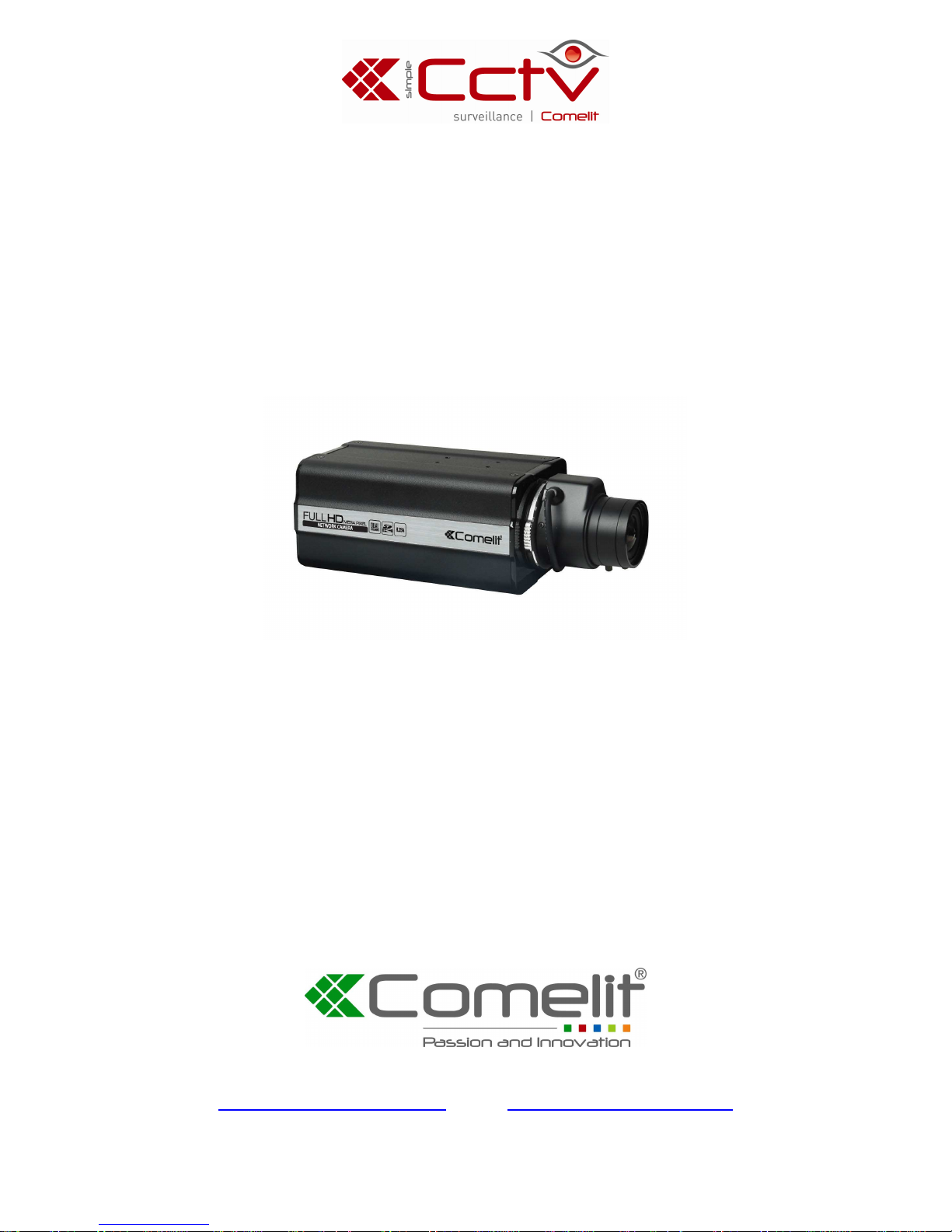
BOX NETWORK CAMERA
ART. IPCAM500A-IPCAM501A-IPCAM502A
Please read this manual thoroughly before use, and keep for future reference.
Via Don Arrigoni, 5 24020 Rovetta S. Lorenzo (Bergamo)
http://www.comelitgroup.com e-mail:[email protected]
Page 2

Page 3
Network Camera
WARNING
RISK OF ELECTRIC SHOCK
DO NOT OPEN
WARNING: TO REDUCE THE RISK OF ELECTRIC SHOCK,
DO NOT REMOVE COVER (OR BACK).
NO USER-SERVICEABLE PARTS INSIDE.
REFER SERVICING TO QUALIFIED
SERVICE PERSONNEL.
COMPLIANCE NOTICE OF FCC:
THIS EQUIPMENT HAS BEEN TESTED AND FOUND TO COMPLY WITH THE LIMITS FOR A
CLASS A DIGITAL DEVICE, PURSUANT TO PART 15 OF THE FCC RULES. THESE LIMITS ARE
DESIGNED TO PROVIDE REASONABLE PROTECTION AGAINST HARMFUL INTERFERENCE
WHEN THE EQUIPMENT IS OPERATED IN A COMMERCIAL ENVIRONMENT. THIS EQUIPMENT
GENERATES, USES, AND CAN RADIATE RADIO FREQUENCY ENERGY AND IF NOT INSTALLED
AND USED IN ACCORDANCE WITH THE INSTRUCTION MANUAL, MAY CAUSE HARMFUL
INTERFERENCE TO RADIO COMMUNICATIONS. OPERATION OF THIS EQUIPMENT IN A
RESIDENTIAL AREA IS LIKELY TO CAUSE HARMFUL INTERFERENCE, IN WHICH CASE USERS
WILL BE REQUIRED TO CORRECT THE INTERFERENCE AT THEIR OWN EXPENSE.
WARNING: CHANGES OR MODIFICATIONS NOT EXPRESSLY APPROVED BY THE PARTY
RESPONSIBLE FOR COMPLIANCE COULD VOID THE USER’S AUTHORITY TO OPERATE THE
EQUIPMENT.
THIS CLASS OF DIGITAL APPARATUS MEETS ALL REQUIREMENTS OF THE CANADIAN
INTERFERENCE-CAUSING EQUIPMENT REGULATIONS.
The information in this manual is believed to be accurate as of the date of publication. We are not responsible
for any problems resulting from the use thereof. The information contained herein is subject to change without
notice. Revisions or new editions to this publication may be issued to incorporate such changes.
The software included in this product contains some Open Sources. You may obtain the
complete corresponding source code from us. See the Open Source Guide on the software CD
(OpenSourceGuide\OpenSourceGuide.pdf) or as a printed document included along with the
User's Manual.
WEEE (
Waste Electrical & Electronic Equipment
)
Correct Disposal of This Product
(Applicable in the European Union and other European countries with separate collection systems)
This marking shown on the product or its literature, indicates that it should not be disposed with other
household wastes at the end of its working life. To prevent possible harm to the environment or human
health from uncontrolled waste disposal, please separate this from other types of wastes and recycle it
responsibly to promote the sustainable reuse of material resources.
Household users should contact either the retailer where they purchased this product, or their local
government office, for details of where and how they can take this item for environmentally safe recycling.
Business users should contact their supplier and check the terms and conditions of the purchase contract.
This product should not be mixed with other commercial wastes for disposal.
i
Page 4
User’s Manual
I
mportant Safeguards
1. Read Instructions
All the safety and operating instructions should be read
before the appliance is operated.
2. Retain Instructions
The safety and operating instructions should be retained
for future reference.
3. Cleaning
Unplug this equipment from the wall outlet before cleaning
it. Do not use liquid aerosol cleaners. Use a damp soft
cloth for cleaning.
4. Attachments
Never add any attachments and/or equipment without the
approval of the manufacturer as such additions may result
in the risk of fire, electric shock or other personal injury.
5. Water and/or Moisture
Do not use this equipment near water or in contact with
water.
6. Placing and Accessories
Do not place this equipment on an wall or ceiling that is
not strong enough to sustain the camera. The equipment
may fall, causing serious injury to a child or adult, and
serious damage to the equipment. Wall or shelf mounting
should follow the manufacturer's instructions, and should
use a mounting kit approved by the manufacturer.
This equipment and cart combination should be moved
with care. Quick stops, excessive force, and uneven surfaces
may cause the equipment and cart combination to overturn.
Do not place this equipment in an enclosed space. Sufficient
ventilation is required to prevent an increase in ambient
temperature which can cause malfunction or the risk of fire.
7. Power Sources
This equipment should be operated only from the type of
power source indicated on the marking label. If you are
not sure of the type of power, please consult your equipment
dealer or local power company.
8. Power Cord
Operator or installer must remove power and TNT
connections before handling the equipment.
9. Lightning
For added protection for this equipment during a lightning
storm, or when it is left unattended and unused for long
periods of time, unplug it from the wall outlet and disconnect
the antenna or cable system. This will prevent damage
to the equipment due to lightning and power-line surges.
10. Overloading
Do not overload wall outlets and extension cords as this
can result in the risk of fire or electric shock.
11. Objects and Liquids
Never push objects of any kind through openings of this
equipment as they may touch dangerous voltage points or
short out parts that could result in a fire or electric shock.
Never spill liquid of any kind on the equipment.
12. Servicing
Do not attempt to service this equipment yourself. Refer
all servicing to qualified service personnel.
13. Damage requiring Service
Unplug this equipment from the wall outlet and refer
servicing to qualified service personnel under the following
conditions:
A. When the power-supply cord or the plug has been
damaged.
B. If liquid is spilled, or objects have hit the equipment. C.
If the equipment has been exposed to rain or water. D. If
the equipment does not operate normally by following
the operating instructions, adjust only those controls
that are covered by the operating instructions as an
improper adjustment of other controls may result in
damage and will often require extensive work by a
qualified technician to restore the equipment to its
normal operation.
E. If the equipment has been dropped, or the cabinet
damaged.
F.
When the equipment exhibits a distinct change in
performance — this indicates a need for service.
14. Replacement Parts
When replacement parts are required, be sure the service
technician has used replacement parts specified by the
manufacturer or that have the same characteristics as the
original part. Unauthorized substitutions may result in fire,
electric shock or other hazards.
15. Safety Check
Upon completion of any service or repairs to this equipment,
ask the service technician to perform safety checks to
determine that the equipment is in proper operating
condition.
16. Field Installation
This installation should be made by a qualified service
person and should conform to all local codes.
17. Correct Batteries
Warning: Risk of explosion if battery is replaced by an
incorrect type. Dispose of used batteries according to the
instructions.
18. Tmra
A manufacturer’s maximum recommended ambient
temperature (Tmra) for the equipment must be specified
so that the customer and installer may determine a suitable
maximum operating environment for the equipment.
ii
Page 5

Network Camera
Table of Contents
Chapter 1 — Introduction ............................................................... 1
1.1 In This Manual .................................................................... 1
1.2 Features.............................................................................. 1
1.3 Typical Applications ............................................................ 2
Chapter 2 — Installation................................................................. 4
2.1 Package Contents .............................................................. 4
2.2 Front Side View................................................................... 4
2.3 Right Side View................................................................... 4
2.4 Rear View ........................................................................... 5
Factory Reset......................................................................... 6
2.5 Installation........................................................................... 7
Manual Iris Lens..................................................................... 7
DC-Type Auto Iris Lens.......................................................... 7
CS-Mount Lens ...................................................................... 8
C-Mount Lens ........................................................................ 8
Bracket ................................................................................... 9
Chapter 3 — Remote Setup ......................................................... 10
3.1 Quick Setup ...................................................................... 11
3.2 System .............................................................................. 11
General ................................................................................ 11
Date/Time ............................................................................ 12
User/Group .......................................................................... 13
3.3 Network............................................................................. 14
IP Address ........................................................................... 14
DVRNS ................................................................................ 15
Port ...................................................................................... 17
Bandwidth Control................................................................ 18
Security ................................................................................ 19
IEEE 802.1X ........................................................................ 20
3.4 Video................................................................................. 21
Camera ................................................................................ 21
Streaming............................................................................. 24
Webcasting .......................................................................... 25
MAT ..................................................................................... 26
3.5 Audio................................................................................. 27
Input/Output ......................................................................... 27
3.6 Event Action...................................................................... 28
Alarm Out ............................................................................. 28
Email .................................................................................... 29
iii
Page 6

User’s Manual
Remote Callback ..................................................................30
Audio Alarm ..........................................................................31
FTP Upload...........................................................................32
Record ..................................................................................33
3.7 Event .................................................................................34
Alarm In ................................................................................35
Motion Detection...................................................................36
Audio Detection ....................................................................37
Video Blind............................................................................38
System Event........................................................................40
Chapter 4 — WebGuard ...............................................................41
Web Monitoring Mode .............................................................43
Web Search Mode ...................................................................45
Appendix .......................................................................................47
LED Indicators .........................................................................47
Connector Pin Outs .................................................................47
Map of Screens (Remote Setup) .............................................48
Troubleshooting .......................................................................49
Specifications ..........................................................................50
iv
Page 7

Network Camera
1
Chapter 1 — Introduction
1.1 In This Manual
This manual is intended for users of the network camera and includes instructions for using
and managing the camera on the network.
1.2 Features
This network camera compresses live video and transmits the video over Ethernet connections.
The camera can be accessed, configured and managed by using the INIT (Integrated Network
Installation Tool) program. It has a built-in web server, WebGuard, allowing you to monitor
live video and search recorded video remotely using a web browser. The remote programs
provided with the camera also allow remote management, monitoring, searching and
recording. This camera offers the following features:
Dual stream for both live monitoring and recording or for live monitoring only
H.264 and M-JPEG compression algorithm
Four levels of video compression and various video compression resolutions
Two-way audio communication
Pre- and post-event buffering and video stream buffering to enhance reliability of network
recording
Remote monitoring and searching via web browser or remote software
Automatic HTML code generation for webcasting on a user’s website
Up to 10
simultaneous connections to the camera for remote monitoring
Enhanced security using IP address filtering, HTTPS, SSL and IEEE 802.1X functions and
password protected multiple user levels
Network bandwidth limit and MAT functions to use network bandwidth efficiently
Convenient network connection using the UPnP (Universal Plug and Play) function and
built-in mDNS (Multicast DNS) protocol
ONVIF protocol supported
WDR (Wide dynamic range) to adjust the image display in high contrast conditions
Slow shutter to reduce the minimum illumination requirements
Day and night functionality with the built-in IR-cut filter changer (not supported in every
model)
Convenient firmware upgrades via the network connection
Firmware duplication and autorecovery functions to enhance system stability
Management of multiple cameras via Ethernet connections
Event detection functions: alarm-in, motion, audio, video blind
SD memory recording to provide redundancy in case of network disconnection
Power sources: 12 VDC, 24 VAC, PoE (Power over Ethernet)
RS485 interface for controlling a Pan/Tilt driver
C/CS mount lens connection
NTSC or PAL programmable video output
Built-in microphone
Page 8
User’s Manual
2
NOTES:
In this manual, a “remote system” refers to a PC that the remote program (RASplus,
iNEX Basic or WebGuard) is running.
Remote monitoring and recording through dual stream are available by using the
RASplus and iNEX Basic programs provided with the camera.
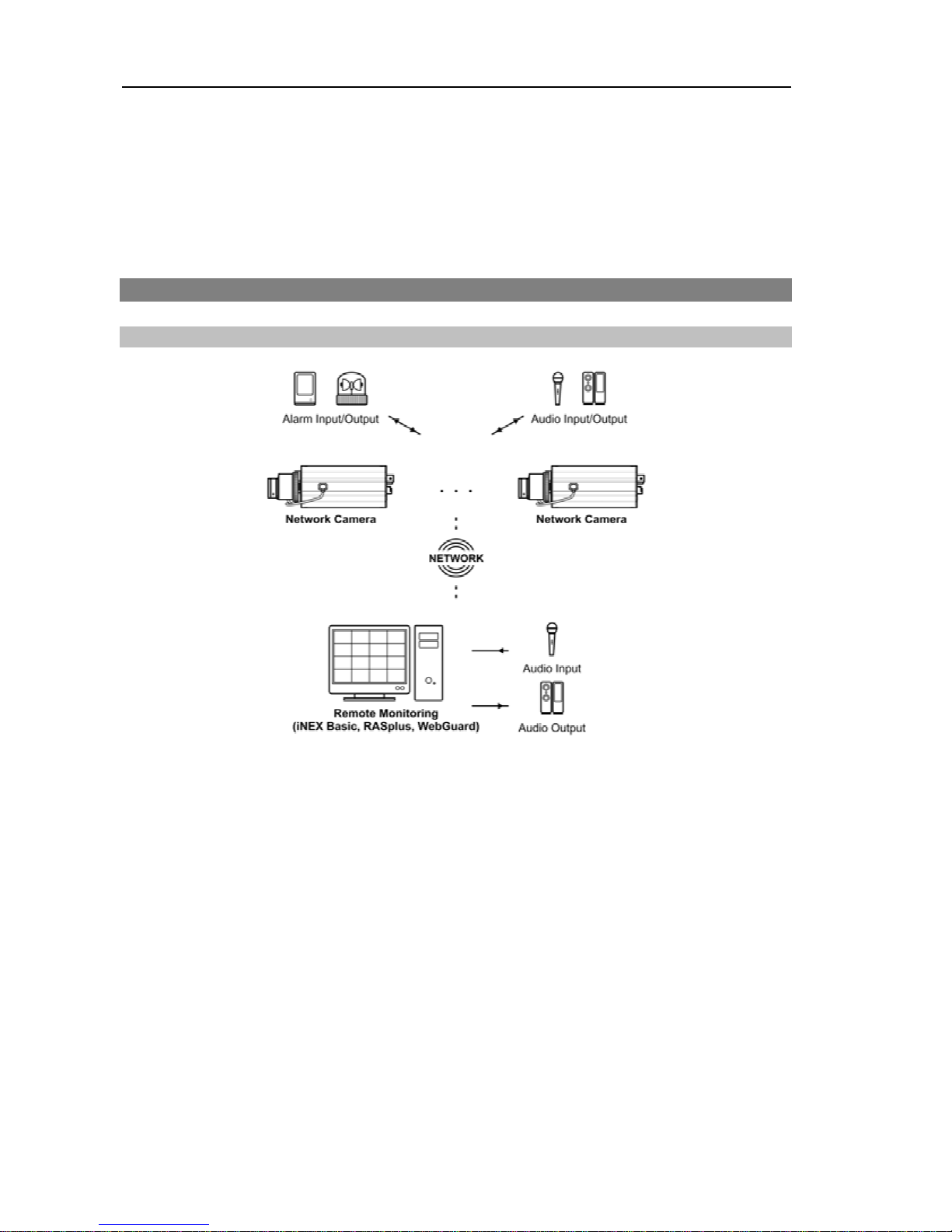
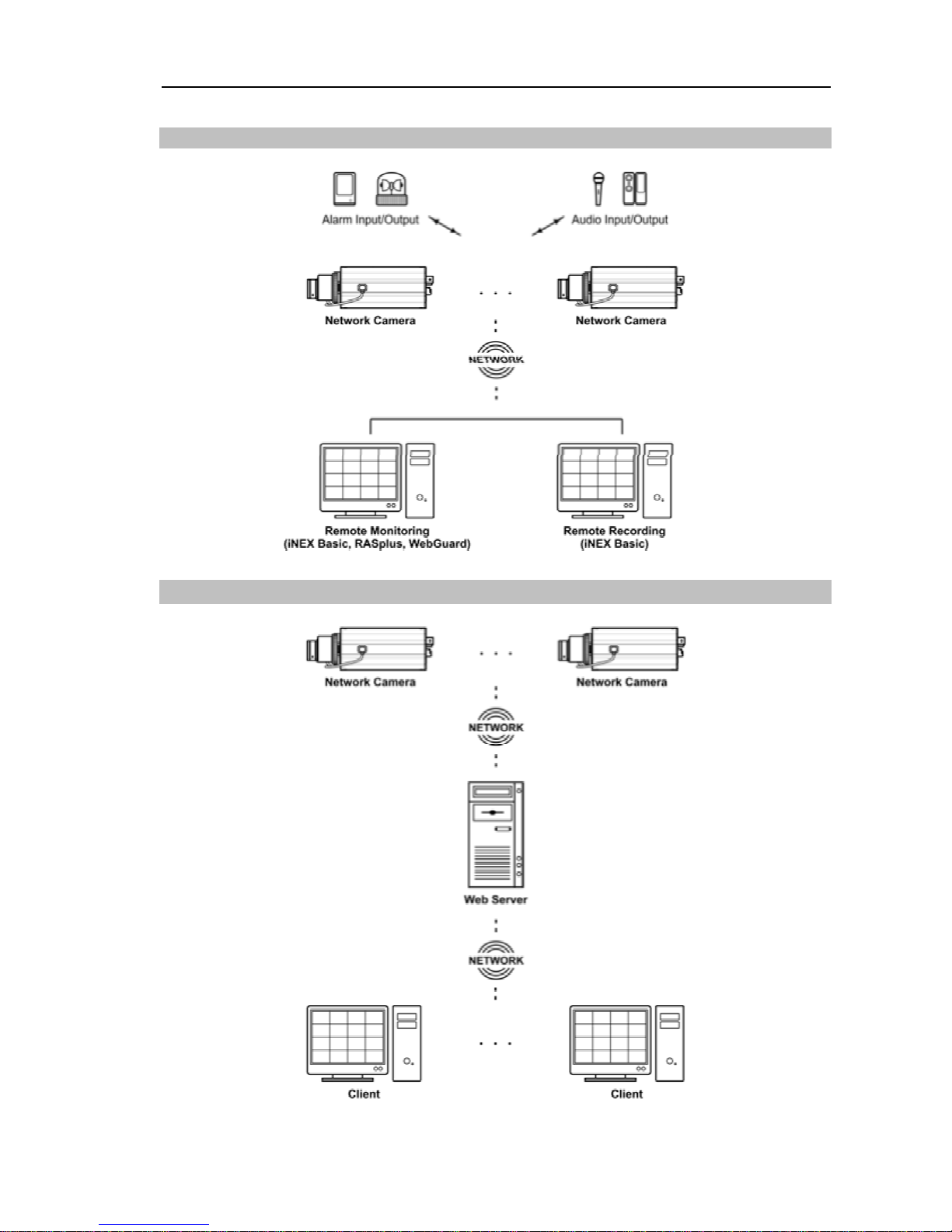
1.3 Typical Applications
Remote Monitoring
Page 9
Network Camera
3
Remote Recording
Webcasting
Page 10
User’s Manual
4
Chapter 2 — Installation
2.1 Package Contents
Network Camera
C-Mount Ring
DC-Type Auto Iris Lens Connector Socket
Protective cover (attached to the unit)
Mount Kits
Installation CD (INIT, RASplus and iNEX Basic software, iNEX Basic User’s Manual)
User’s Manuals (Camera, INIT, RASplus)
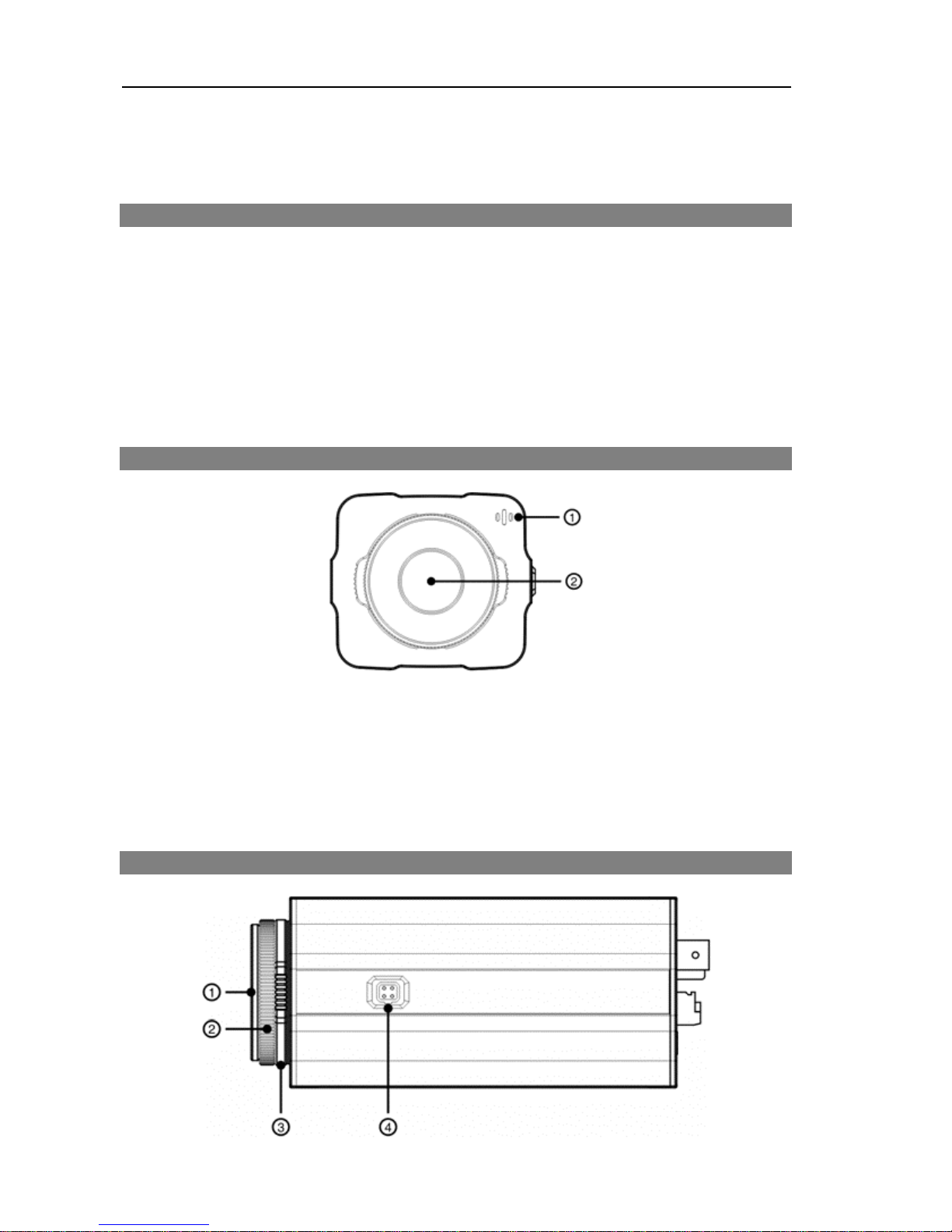
2.2 Front Side View
Built-In Microphone: Receives audio.
Image Sensor: Converts an optical image of the object to an electric signal.
NOTE: Cover the image sensor by using the protective cover provided with the camera
when a lens is not mounted on the camera.
2.3 Right Side View
Page 11
Network Camera
5
Protective cover: Attach when a lens is not installed to protect the image sensor.
C-Mount Ring: Attach the ring provided with the camera to the camera when using the C-Mount
lens.
Back Focus Adjustment Ring: Loose screws and adjust the back focus by turning the ring
clockwise or counter-clockwise, and then tighten the screws to fix the current back focus.
Auto Iris Lens Connector: Connect the auto iris jack if the lens is a DC-type auto iris lens.
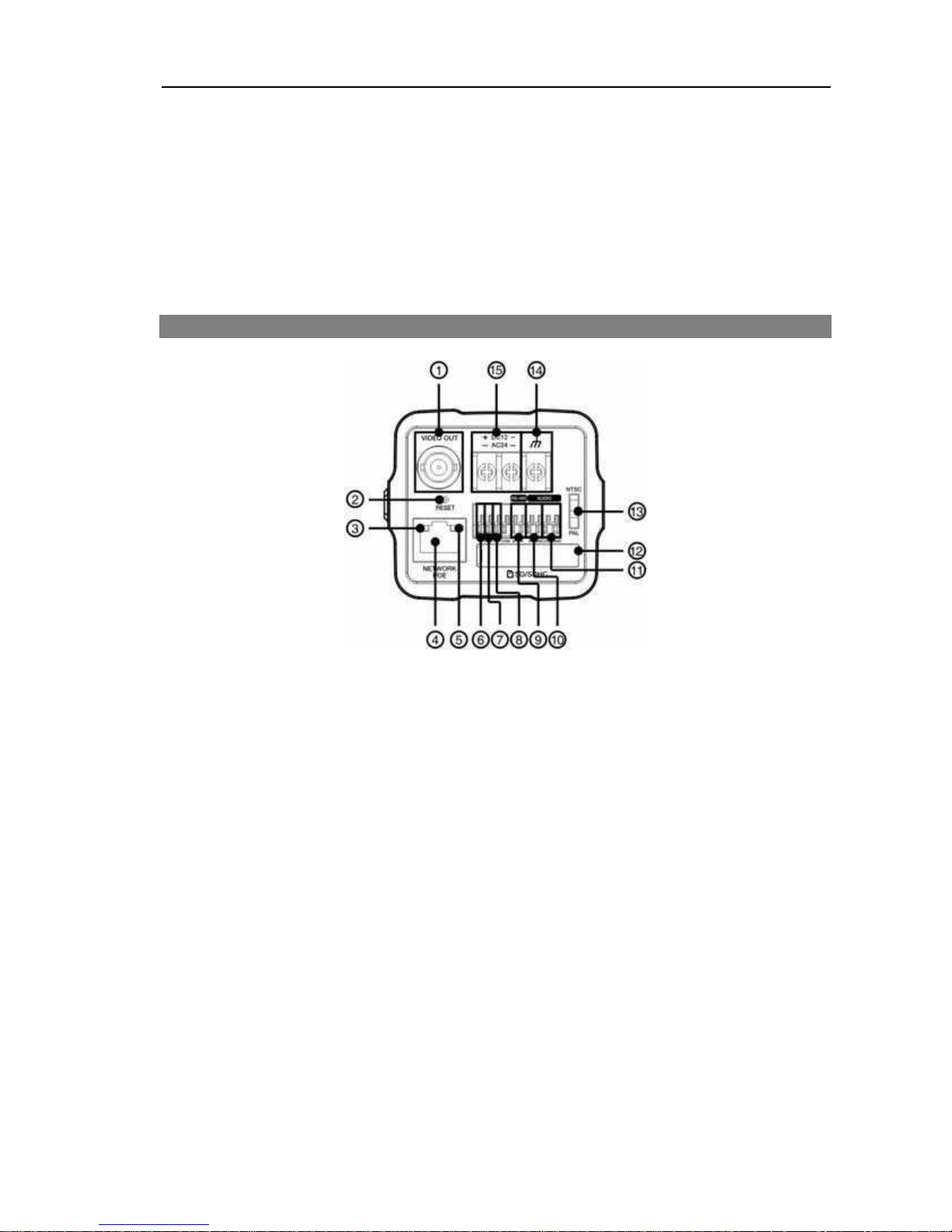
2.4 Rear View
Video Out: Connect to a monitor. This is intended for video preview while adjusting the camera.
Factory Reset Switch: Use to return all settings to the original factory settings. See below
for details.
Network LED: Indicates network connection status. See Appendix – LED Indicators for
details.
Network Port: Connect a Cat5 cable with an RJ-45 connector. Refer to the INIT User’s Manual
for details about network connection setup. When using a PoE switch, the camera can be
supplied with power over Ethernet cable (Refer to the PoE switch manufacturer’s manual for
details).
Power LED: Indicates system operation status. See Appendix – LED Indicators for details.
Alarm Input: Connect alarm-in devices. Mechanical or electrical switches can be wired to
the AI (Alarm-In) and GND (Ground) connectors. The voltage range is from 0V to 5V. When
the electrical switch is wired, the threshold voltage for NC (Normally Closed) is above 4.3V
and for NO (Normally Open) is below 0.3V, and it should be stable at least 0.5 seconds to be
detected.
GND: Connect to the ground side of the alarm inputs.
Alarm Output: Connect an alarm-out device to the NO (Normally Open) and COM (Common)
connectors. NO is a relay output which sinks 0.3A @ 125 VAC and 1A @ 30 VDC.
RS485 Port: Connect to a Pan/Tilt driver. Connect TX+/RX+ and TX-/RX- of the driver to
the + and – (respectively) of the camera. Refer to the Pan/Tilt driver manufacturer’s manual
for configuring the RS485 connection.
Page 12

User’s Manual
6
Audio In: Connect to an audio source (Line-in). The built-in microphone is supported on the
front.
11-
Audio Out: Connect to an amplifier (Line-out). The camera does not have amplified audio
output, so you will need a speaker with an amplifier.
12-
SD Memory Card Slot: Pull out the cover and insert an SD memory card.
13-
Video Signal Switch: Select the video signal between NTSC and PAL for video output.
14-
GND: Connect to the ground side of the power in.
15-
Power In: Loose the screws of power connector by turning the screw counter-clockwise and
connect two wires from the power adapter (12 VDC or 24 VAC). You do not need to distinguish
power polarity when connecting the wires. The camera starts booting as soon as power is
applied.
NOTES:
To make connections on the Alarm Connector Strip, press and hold the button and
insert the wire in the hole below the button. After releasing the button, tug gently on
the wire to make certain it is connected. To disconnect a wire, press and hold the button
above the wire and pull out the wire.
Camera and audio surveillance may be prohibited by laws that vary by region. Check
the laws in your area before using this product for surveillance purposes.
CAUTIONS:
The camera restarts after the power adaptor is disconnected from the camera
when switching the power source from 12 VDC or 24 VAC to PoE.
The network connector is not designed to be connected directly with cable
or wire intended for outdoor use.
Do
NOT remove the SD memory card while the unit is operating; otherwise,
the system might not operate properly and recorded data saved on it might
be damaged.
WARNING: ROUTE POWER CORDS SO THAT THEY ARE NOT A TRIPPING
HAZARD. MAKE CERTAIN THE POWER CORD WILL NOT BE PINCHED OR
ABRADED BY FURNITURE. DO NOT INSTALL POWER CORDS UNDER RUGS
OR CARPET. USE THE POWER CORD THAT HAS A GROUNDING PIN. IF
YOUR POWER OUTLET DOES NOT HAVE A GROUNDING PIN RECEPTACLE,
DO NOT MODIFY THE PLUG. DO NOT OVERLOAD THE CIRCUIT BY PLUGGING
TOO MANY DEVICES INTO ONE CIRCUIT.
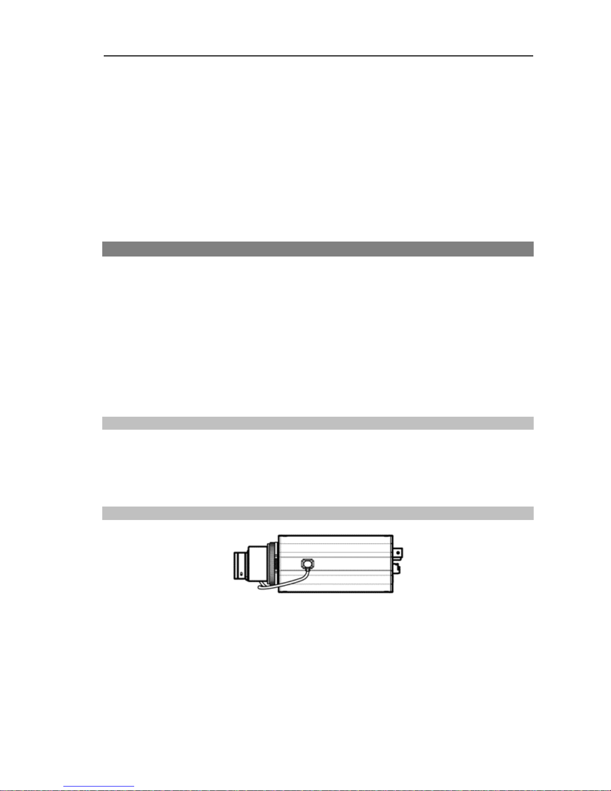
Factory Reset
This switch will only be used on the rare occasions that you want to return all the settings
to the original factory settings.
CAUTION: When performing a Factory Reset, you will lose any settings you
have
saved.
Page 13
Network Camera
7
Cut off the power from the camera. Poke a straightened paperclip into the factory reset
switch hole. Turn on the power while holding the reset switch. Release the switch in about
5 seconds after the Power LED blinks. The camera resets to factory defaults and restarts
after completing the factory reset.
You can perform a factory reset while the camera is turned on by poking a straightened
paperclip into the factory reset switch hole and releasing the reset switch. A factory reset
also can be performed remotely by running the INIT program. The camera restarts after
completing the factory reset. Refer to the INIT User’s Manual for details on remote factory
resetting.
2.5 Installation
A lens is not supplied with the camera. Ask your dealer or distributor about purchasing one.
The camera supports manual iris and the DC-type auto-iris lenses, and it accepts CS- and
C-mount lenses.
NOTES:
A mega-pixel lens is recommended for the best image resolution.
Video-type auto-iris lenses are not supported.
Use a lens that weighs less than 1.0 lbs. (450g). If the lens weighs too much, the camera
might become unstable.
Manua
l Iris
Lens
1. Remove the protective cover from the camera.
2. Mount the lens on the camera by turning the lens clockwise.
3. Turn the iris ring on the lens to the open position and adjust the iris properly.
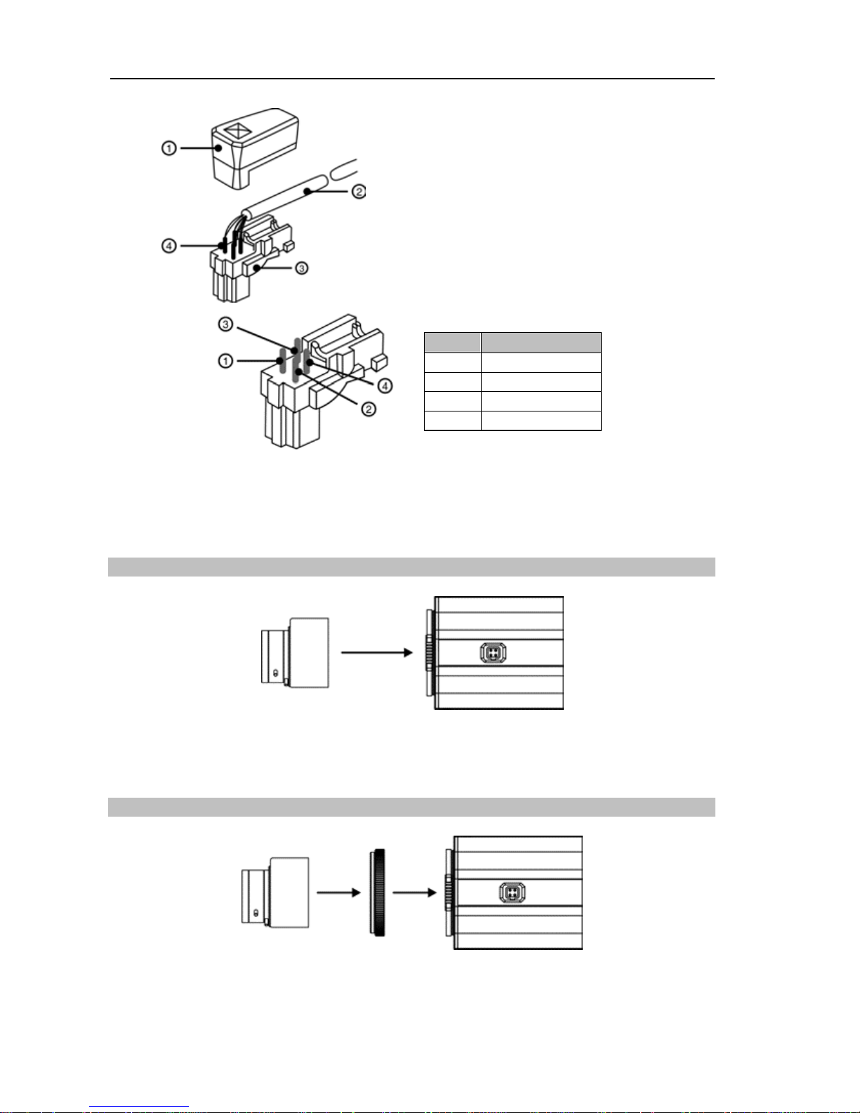
DC-Type Auto Iris Lens
1. If necessary, solder the lens control wires to the connector socket supplied with the lens.
NOTE: Please refer to the lens manufacturer’s manual for soldering the lens control wires.
Page 14
User’s Manual
8
PIN
Name
1
Damp Coil –
2
Damp Coil +
3
Drive Coil +
4
Drive Coil –
Connector Socket Cover
IRIS Control Cable
Connector Socket
Heat Shrink Tubing
2. Remove the protective cover from the camera.
3. Mount the lens on the camera by turning the lens clockwise, and then connect the auto
iris jack to the auto iris lens connector.
CS-Mount Lens
1. Remove the protective cover from the camera.
2. Mount the CS-mount lens on the camera by turning the lens clockwise.
C-Mount Lens
1. Remove the protective cover from the camera.
2. Mount the C-mount ring on the camera by turning the ring clockwise.
3. Mount the C-mount lens on the C-mount ring by tuning the lens clockwise.
Page 15

Network Camera
9
Bracket
You can attach a bracket to the bottom or top of the camera to mount it. Use 1/4–20 UNC
(20 Thread), 2.5mm +/- 0.2 mm (ISO Standard) or 0.197 (ASA Standard) standard screws
when attaching the bracket.
Page 16
User’s Manual
10
Chapter 3 — Remote Setup
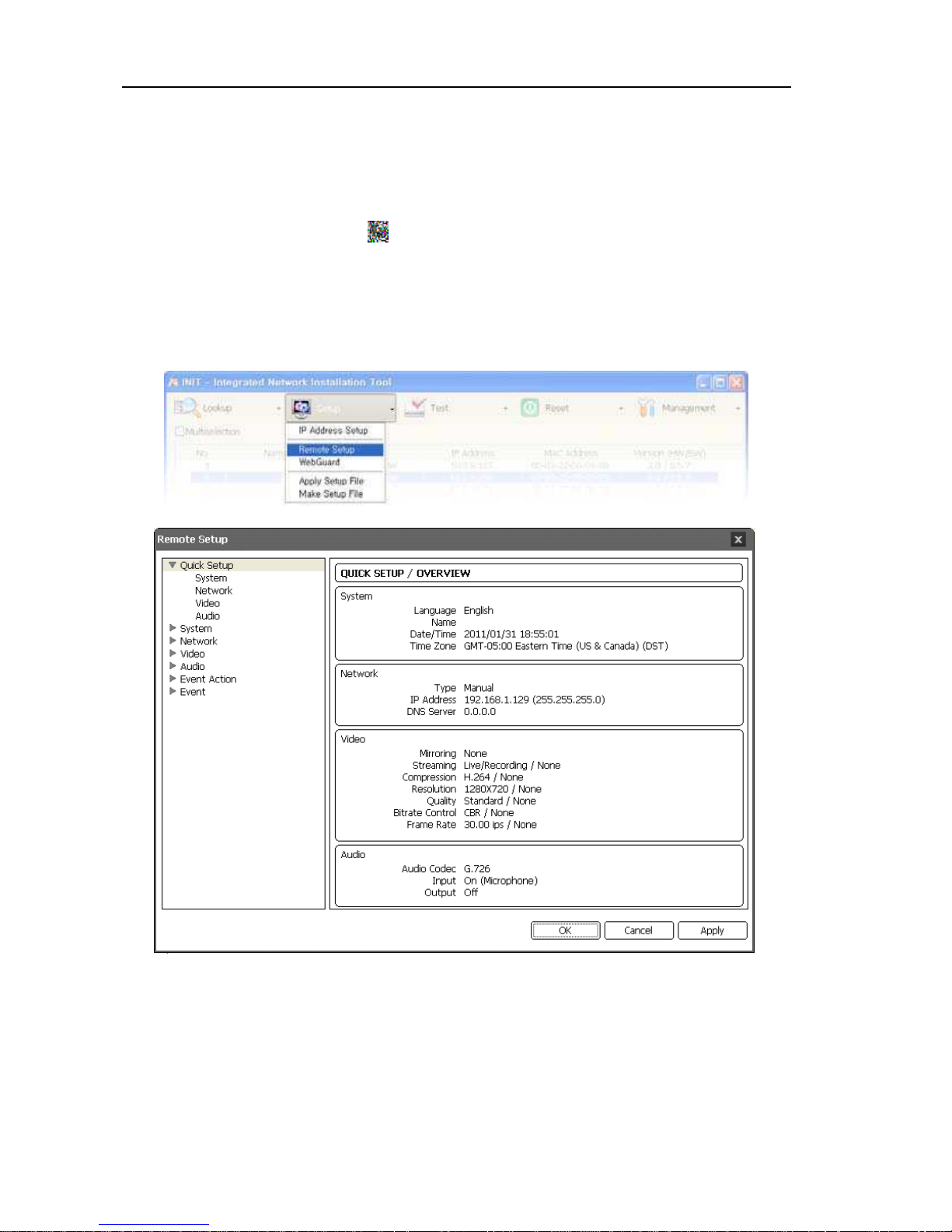
Remote Setup allows you to change all settings of a camera. Run the INIT program, select a
camera and click the Setup icon
on
the Main screen. Select Remote Setup from the
Setup menu and the Remote Setup screen appears. You can also display the Remote
Setup screen by selecting a camera, clicking the right mouse button and selecting Remote
Setup on the Main screen.
NOTE: You can also change the settings by using remote programs.
Clicking a menu on the left side of the Remote Setup screen displays the current settings
for that menu on the right side of the screen. Clicking a submenu under each menu allows
you to change the settings. Clicking the OK button closes the Remote Setup screen and
applies the changes.
Page 17
Network Camera
11
3.1 Quick Setup
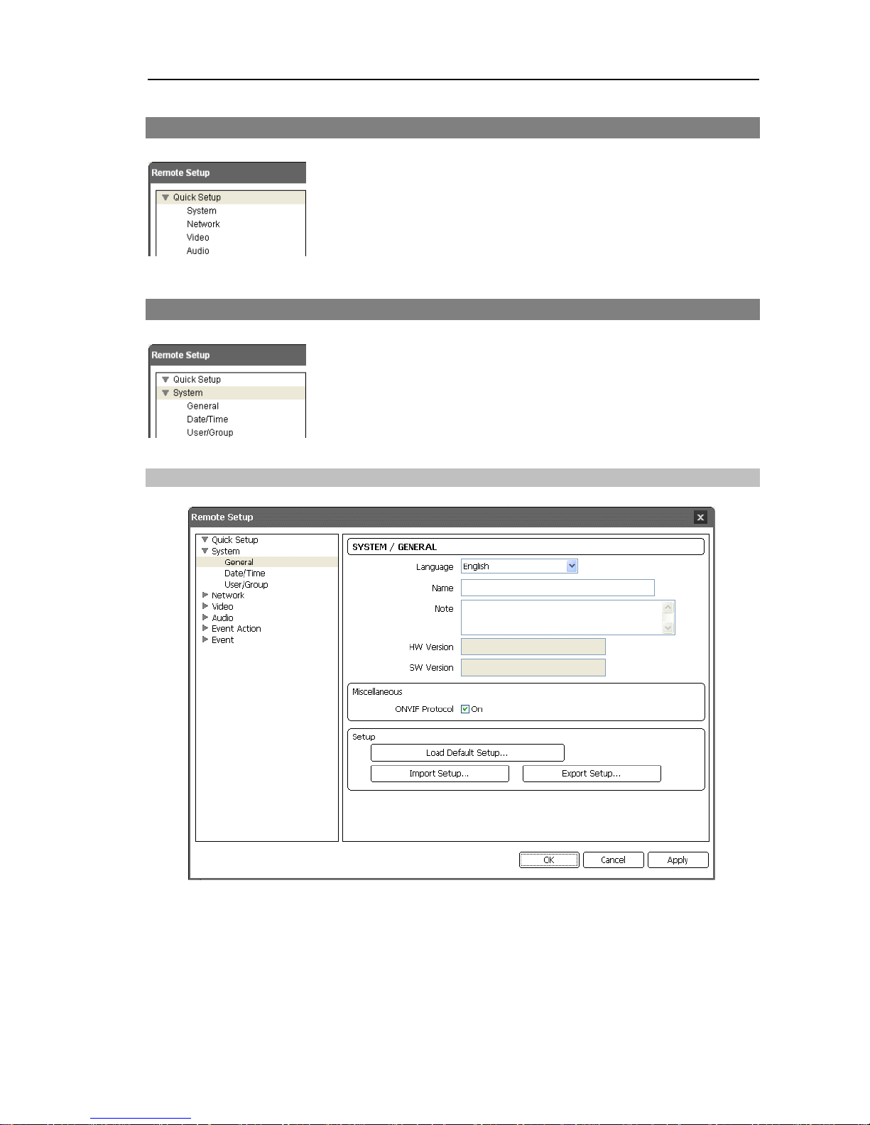
The Quick Setup allows you to change a camera’s basic system,
network, video and audio settings.
3.2 System
You can change a camera’s system information, import or export
all settings, and add users or groups.
Genera
l
Language:
Choose the language to be used during remote setup.
Name:
Enter the camera name (up to 31 characters including spaces).
Note:
Enter additional information about the camera.
HW
Version, SW
Version:
These fields display the camera’s hardware and software
versions.
ONVIF
Protocol: Check the box to enable the ONVIF protocol.
Page 18
User’s Manual
12
Setup
:
Load Default Setup…: Click to return all settings except date/time to the original factory
settings. You can select whether or not network settings will be included when the setup
is applied. Refer to the 3.3 Network for details of the network settings.
Import Setup…: Click to apply the settings saved as a .dat file format to the camera. A
setup screen appears allowing you to select the setup file. You can select whether or not
to include network settings (except DVRNS setting) when the setup is applied. Refer to the
3.3 Network for details of the network settings.
Export Setup…: Click to save the current camera settings as a .dat file format. A setup
screen appears allowing you to name the setup file.
NOTES:
The Load Default Setup and Import Setup functions are permitted only to the users in
the Administrator group.
Do NOT check the Include Network Setup box when the network settings of the setup
file are used in another camera. Otherwise, the connection to the camera might not
be made properly.
If the IP address, admin port number or SSL settings are changed during Setup, Remote
Setup closes after saving the changes.
Date/Time
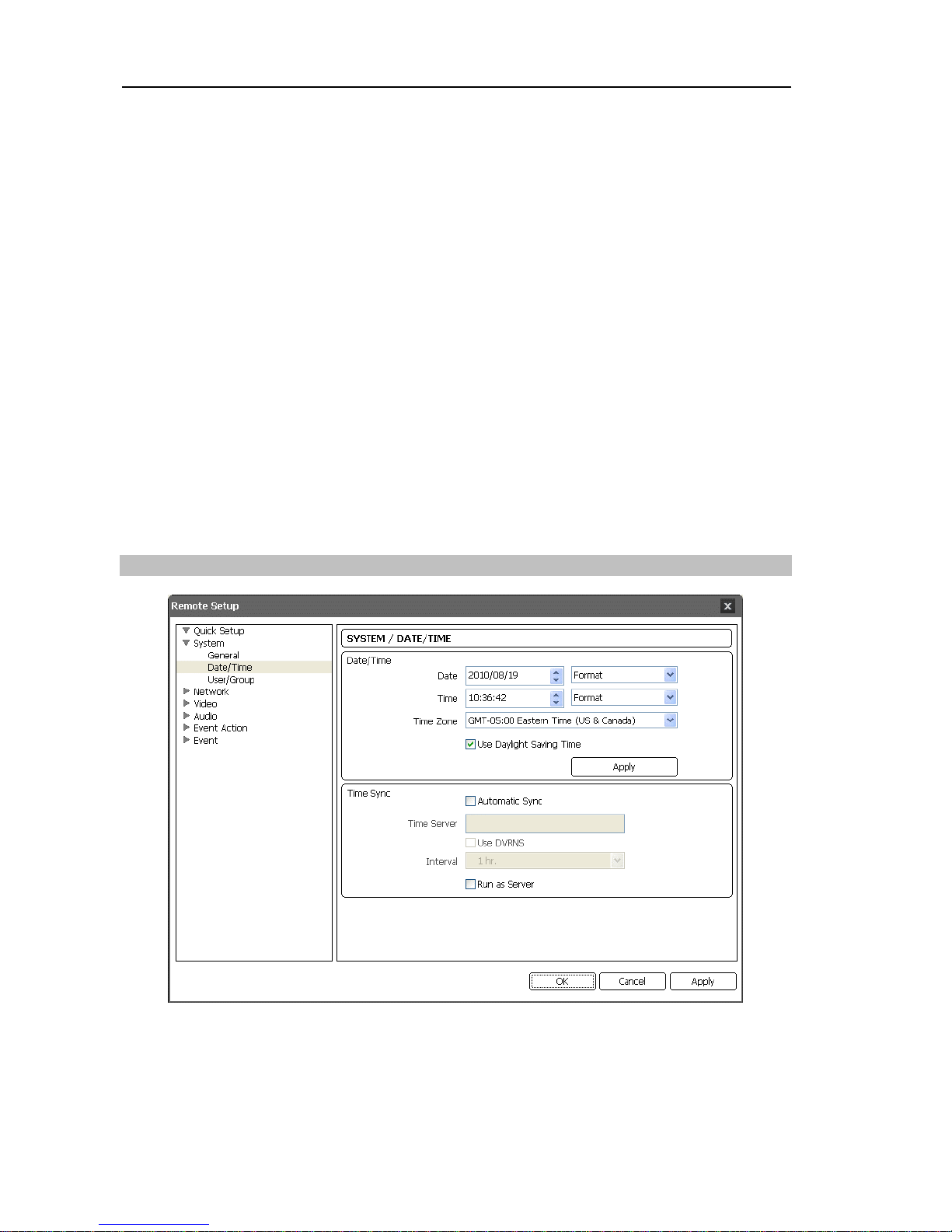
Date/Time:
Change the system date/time, date/time format and time zone. Turn daylightsaving time on or off by checking the box. Clicking the Apply button applies the changes
immediately.
Time Sync
Page 19
Network Camera
13
Automatic Sync: Check the box to automatically synchronize the time with a time server.
Enter the IP address or the domain name of the time server and set the time interval for
synchronization. If the time server uses the DVRNS function, selecting the Use DVRNS box
allows you to enter the name instead of the IP address or the domain name of the time server.
Run as Server: Check the box to run the camera as a time server.
NOTE: If you want to use a domain name instead of the IP address of the time server,
the DNS server must be set up properly when setting Network – IP Address setup. If
you want to use a name instead of the IP address or the domain name of the time server,
the DVRNS function must be set up properly when setting the Network – DVRNS setup.
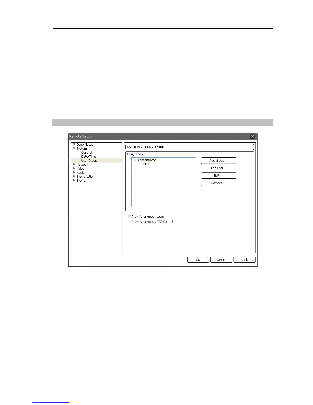
User/Group
User/Group:
Click the buttons to change the settings for a group or a user allowed
controlling the camera remotely.
Add Group: Click to add a group. Enter the group name and set authority levels for the
group to control the camera remotely.
Add User: Click to add a user. Enter the user name and select the group that the user will
belong to. Enter the password to be assigned to the user.
Edit: Select a group and click the button to change authority levels assigned to the group,
or select a user and click the button to change the user’s password.
Delete: Select a group or user and click the button to delete the group or user.
Allow Anonymous Login:
Check the box to use the webcasting feature. Refer to 3.4
Video – Webcasting for details.
Allow Anonymous PTZ Control:
Check the box to allow remote control of a Pan/Tilt
driver
on a
website by using the webcasting feature.
Page 20
User’s Manual
14
NOTES:
Only users belonging to the Administrator group can make User/Group changes.
There is no default password for the admin user in the Administrator group.
The authority levels that can be assigned are:
– Upgrade: The user can upgrade the software.
– Setup: The user can set up the system.
– Color Control: The user can control brightness, contrast, hue and saturation for cameras.
– PTZ Control: The user can control pan and tilt of the Pan/Tilt driver.
– Alarm-Out Control: The user can reset the output during an alarm.
– System Check: The user can view and check the remote system status.
– Search: The user can search video recorded on the SD memory card by using a
remote program.
– Clip Copy: The user can export video recorded on the SD memory card as a video
file by using a remote program.
3.3 Network
You can change the network settings, set up the DVRNS and
security functions and control the network bandwidth.
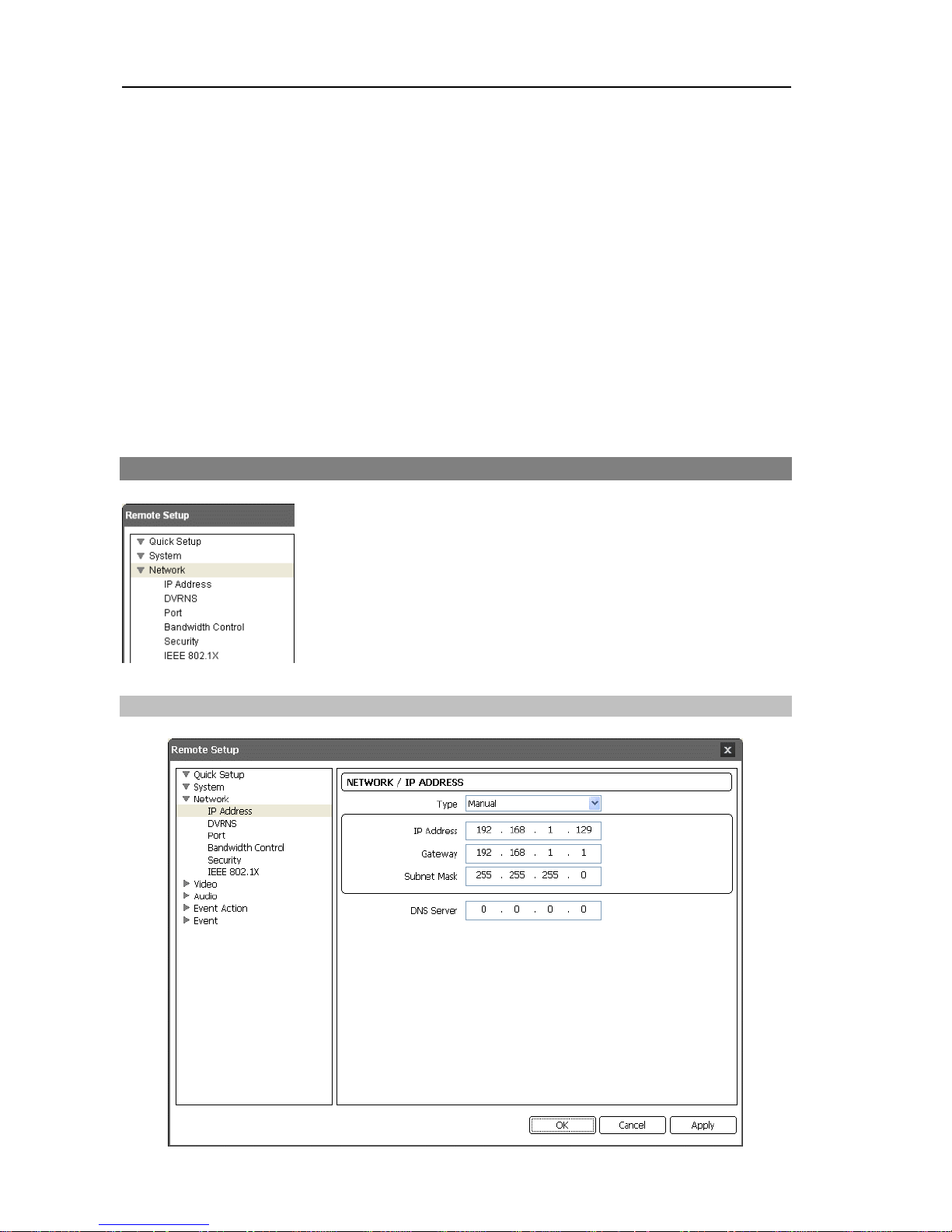
IP
Address
Page 21
Network Camera
15
Type:
Select the type of network configuration. Remote Setup closes after saving the
changes.
Manual: Select when the camera is using a static IP address for network connection, and
set up LAN parameters manually.
DHCP: Select when the camera is networked via DHCP (Dynamic Host Configuration
Protocol). Click the OK button, and a temporary IP address is automatically assigned to
the camera. The camera periodically will be issued a new IP address automatically.
ADSL: Select when the camera is networked via ADSL. Enter the ID and password for ADSL
connection, and click the OK button. A temporary IP address is automatically assigned to
the camera. The camera periodically will be issued a new IP address automatically.
DNS Server:
Enter the IP address of the DNS server. If you set up the DNS server, the
domain name of the server can be used instead of the IP address during the DVRNS, time
or SMTP server setup. Ask your Internet service provider for the IP Address of the DNS
Server.
NOTES:
Ask your network provider for details about the network connection type and connection
information for the camera or the IP address of the DNS server.
If the camera is configured for a DHCP or ADSL network, it is best to use the DVRNS
function because the camera IP address might change frequently.
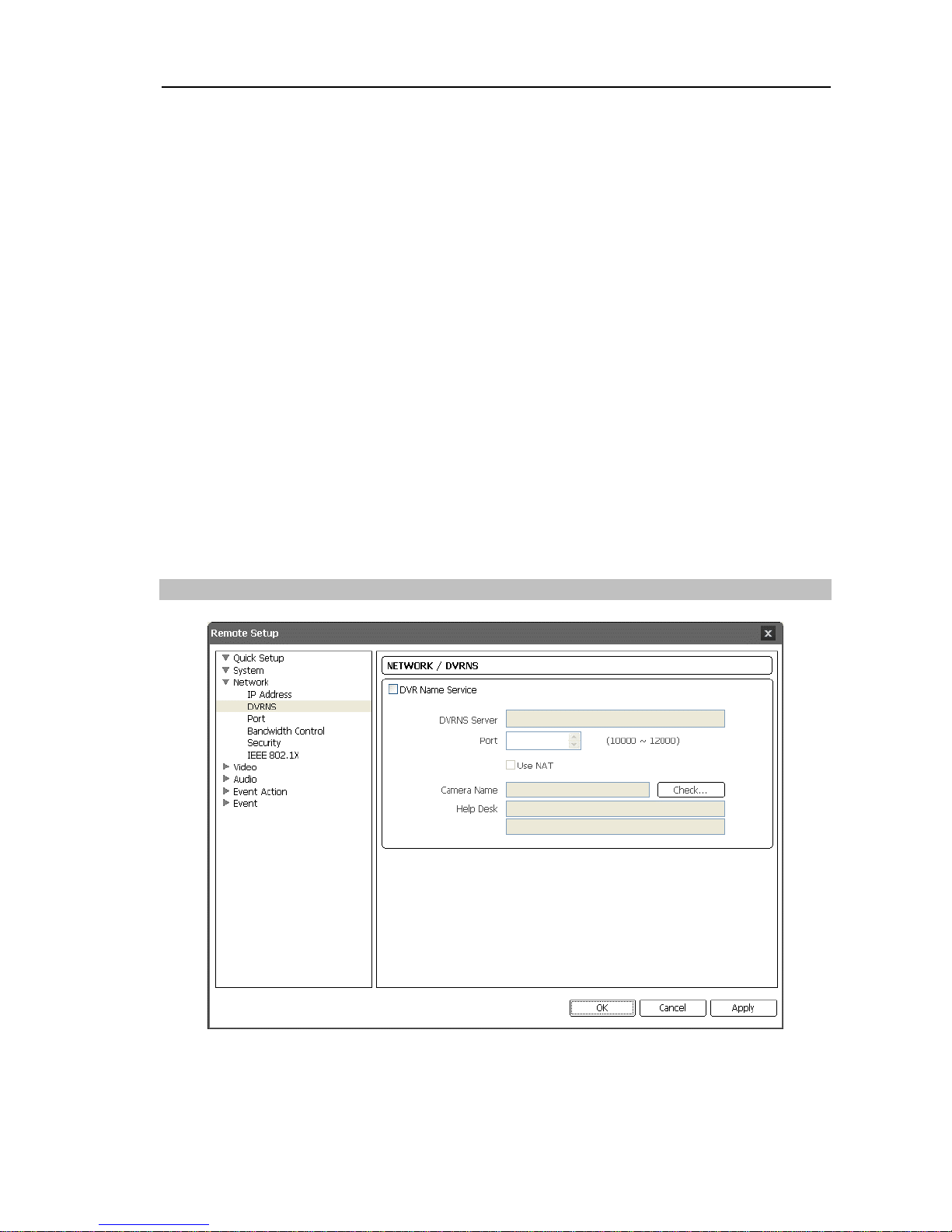
DVRNS
Check the DVR Name Service box to use the DVRNS function.
DVRNS Server:
Enter the IP address or domain name of the DVRNS server.
Port:
Set up the port number of the DVRNS server.
Page 22

User’s Manual
16
Use NAT:
Check the box when the camera uses a NAT (Network Address Translation)
device for network connection.
Camera Name:
Enter the camera name to be registered on the DVRNS server. Check
whether or not the name is available by clicking the Check button.
Help Desk:
Choosing the OK button registers the camera on the DVRNS server. Proper
DVRNS settings will display the help desk information of the DVRNS server.
NOTES:
The DVRNS (DVR Name Service) function allows the camera to use dynamic IP
addresses for remote connection. When using this function, you can access the camera
remotely by using the camera name instead of its IP address. Eor the DVRNS function
to work properly, the camera should be registered on the DVRNS server, and the DVRNS
server settings in the INIT program for the camera should match the settings registered
on the DVRNS server. Any changes on the DVRNS server might cause improper
operation.
When LAN settings are changed, set up the DVRNS settings after saving your LAN
changes by clicking the OK button.
You will need to get the IP address or domain name of the DVRNS server from your
network administrator. You can use the domain name instead of IP address if you set
up the DNS server during the IP Address setup.
When using a NAT (Network Address Translation) device, refer to the NAT manufacturer’s
instructions for the proper network settings.
The camera name you entered in the Camera Name field should be checked by clicking
the Check button, otherwise the DVRNS changes will not be saved. When entering no
name or a name already registered on the DVRNS server, an error message displays.
If a camera name includes the #, \, or % characters, connections to the camera using a
WebGuard program might fail.
Page 23
Network Camera
17
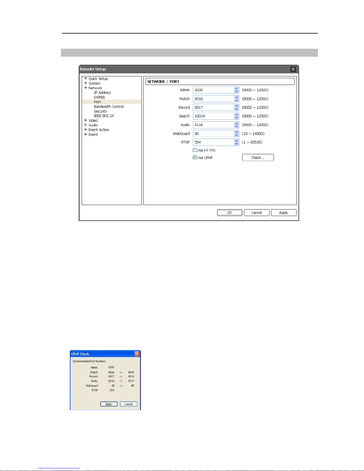
Port
Admin,
Watch,
Record,
Search,
Audio,
WebGuard,
RTSP:
Enter port numbers for
connections to the camera by using the remote programs or media players, such as VLC
Player, supporting RTSP (Real-Time Streaming Protocol) service. Remote Setup closes
after saving the changes (Admin port number only).
Use HTTPS:
Check the box to enhance the security of WebGuard pages by using the
HTTPS protocol when running the WebGuard program.
Use UPnP:
Check the box to connect to the camera without manually setting up port
forwarding on the NAT device when the camera uses a NAT (Network Address Translation)
device for network connection. The UPnP function must also be enabled in the NAT
device for this function to work. Refer to the NAT device User’s Manual for details on
enabling the UPnP function in the NAT device. Clicking the Check button checks the
current port settings. A success message is displayed if all the current port numbers are
available, and recommended port numbers are displayed if any of the current port numbers
are not available.
Clicking the Apply button applies the recommended port
numbers.
Page 24
User’s Manual
18
NOTES:
Do NOT use the same port number for more than one function. If you do, the camera
cannot be connected with the remote programs.
You can access the camera and monitor live video images using media players, such
as VLC Player, supporting RTSP service. It might not be supported, depending on the
type of media player, and some media players might play video properly depending
on network conditions or compression or resolution of images for streaming. You can
access as follows:
–
Access from a PC: Start the media player and enter “rtsp://ID:Password@IP address:
RTSP port number/track ID=‘stream number’”
– Access from mobile devices: Start web browser on the mobile device and enter
“http://IP address:WebGuard port number/” (When using NAT (Network Address
Translation) or firewall services, opening all UDP ports is required to access the
camera using Blackberry and Android devices.)
CAUTIONS:
When changing the port settings, you must change the port settings on
remote programs too.
When using the HTTPS protocol, the ONVIF protocol might not work.
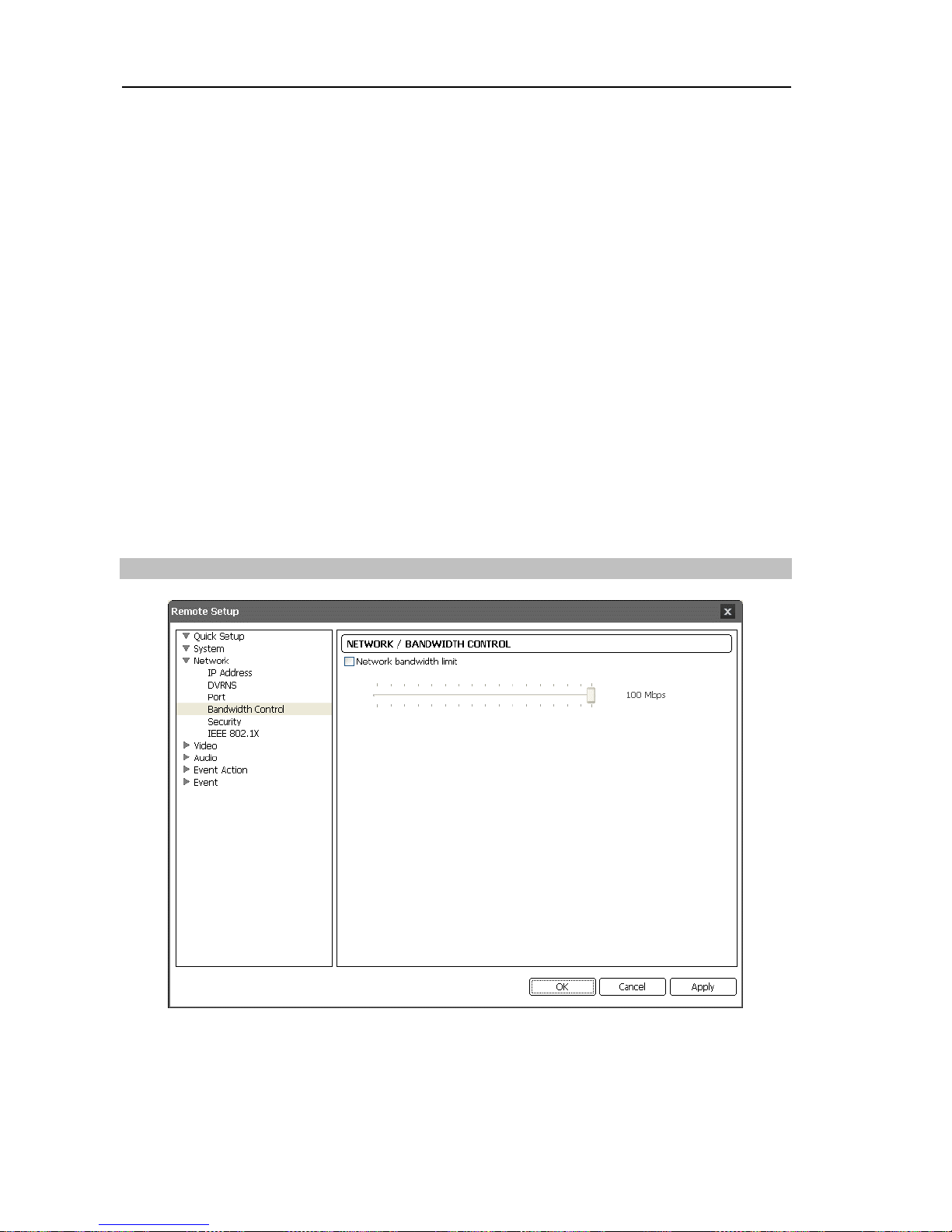
Bandwidth Contro
l
You can control the network bandwidth by limiting the network bandwidth depending on
the network traffic.
Check the Network bandwidth limit box and set the desired maximum bandwidth.
Page 25
Network Camera
19
NOTE: When limiting the network bandwidth, the frame rate might decrease to lower than
the frame rate set during the 3.4 Video – Live Monitoring setup.
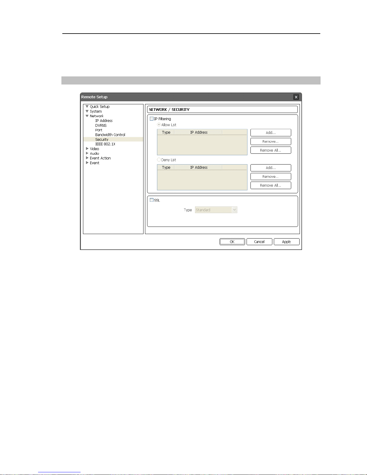
Security
IP
Filtering:
Check the box to use the IP filtering function. You can allow or block
connections to the camera by designating IP addresses.
Add: Click the button to add IP addresses to the Allow List or Deny List to allow or block
connection to the camera. Selecting the Host option allows you to add one IP address at a
time. Selecting the Group option allows you to add continuous IP address numbers in one
action by designating a range of IP addresses to add.
Remove, Remove All: Click the button to remove the selected IP address or all IP addresses
from Allow List or Deny List.
SSL:
Check the box to use the SSL function. You can enhance the security of outgoing
data from the camera by using the SSL (Secure Sockets Layer) protocol. When using
the SSL function, the camera cannot be connected with a program or a system that does
not support the SSL function. Remote Setup closes after saving the changes.
NOTES:
If you want to use the time synchronization, DVRNS and Email sending functions, the
connection of the IP addresses of the time server, DVRNS server and the SMTP server
must be allowed when you set up the IP filtering function. Any connection to the camera
from the IP address in Deny List will NOT be allowed.
Using the SSL function might cause congestion in the system receiving data from the
camera depending on the security level.
This product includes software developed by the OpenSSL Project for use in the
OpenSSL Toolkit (http://www.openssl.org/)
Page 26
User’s Manual
20
I
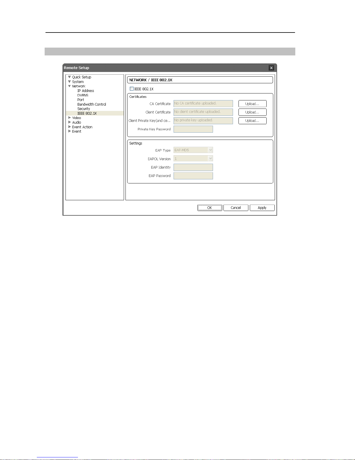
EEE 802.1X
Check the IEEE 802.1X box to use the IEEE 802.1X network connection authentication
function.
Certificates:
Uploads a certificate or private key for network connection depending on
the authentication type. Entering a private key password might be required depending
on the authentication type.
Settings:
Sets up EAP (Extensible Authentication Protocol).
EAP Type: Select the type of authentication to be used for network connection
authentication. The authentication type must be identical to the authentication type that
the authentication server uses.
EAPOL Version: Select the EAP version.
EAP Identity, EAP Password: Enter the ID and password for the authentication.
NOTE: For the IEEE 802.1X network connection authentication function to work properly,
the authentication server and AP should support the IEEE 802.1X authentication.
Page 27
Network Camera
21
3.4 Video
You can set up camera setting and features for streaming,
webcasting and MAT.
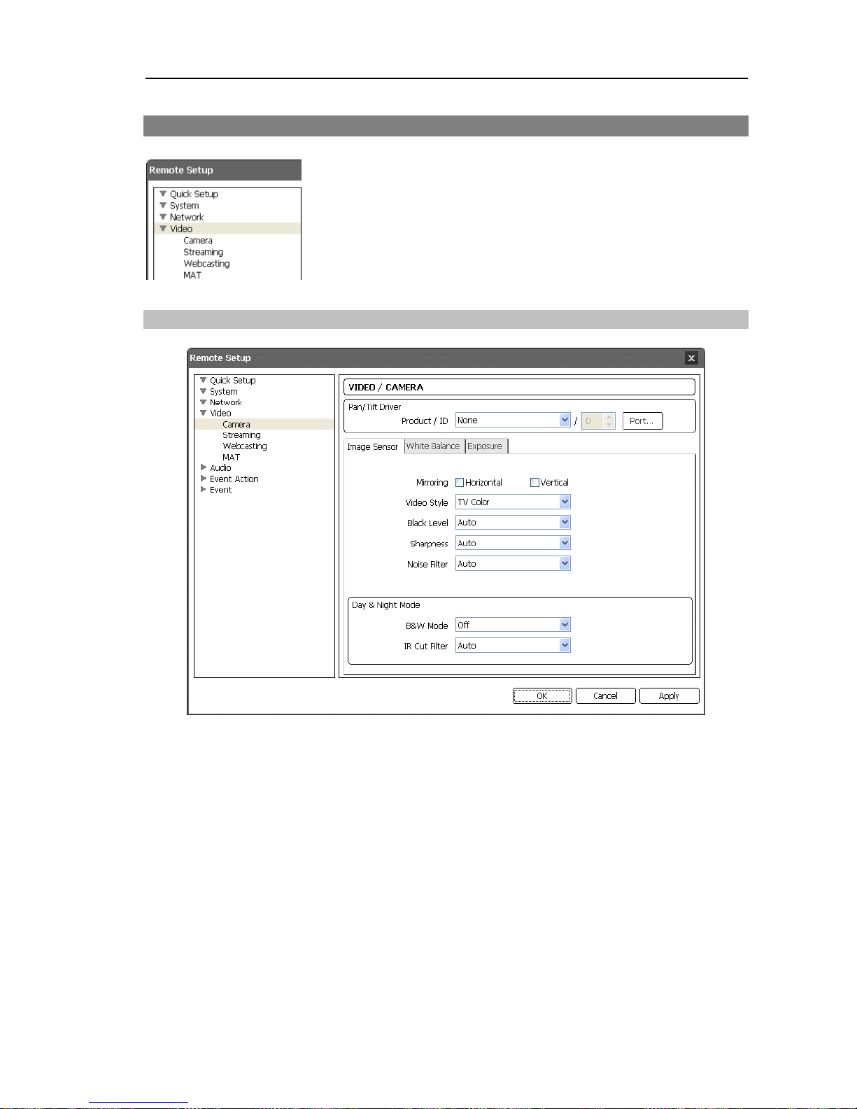
Camera
Pan/Tilt Driver / ID:
Select a Pan/Tilt driver and assign an ID to the Pan/Tilt driver.
Clicking the Port button allows you to set up baud rate, data bit, stop bit and parity. Refer
to the Pan/Tilt driver manufacturer’s instructions.
NOTE: You will not be able to control the Pan/Tilt driver if it is not connected to the RS485
port properly. See Chapter 2 – Installation, 2.4 Rear View and the Pan/Tilt driver
manufacturer’s manual for configuring the RS485 connection.
Image Sensor:
Click the tab to set up image sensor settings.
Mirroring:
Check the Horizontal or Vertical box to flip images horizontally or vertically.
Video Style:
Select the video style between TV Color and PC Color. It is
recommended
to select PC Color (2) when the images are bluish.
Black Level:
Set the black level. The system changes the standard level for black and adjusts
dark and bright images. The higher the value is set, the darker the overall images are.
Page 28
User’s Manual
22
Sharpness:
Set the sharpness of images. The camera adjusts the edges in images to enhance
the sharpness of images. The higher the value is, the sharper the images appear but it
might cause increased image noise when the value is too high.
Noise Filter:
Set the degree of the noise filtration. This adjustment can be used to decrease
noise in low light conditions. The higher the value is set, the less the noise there is.
However, too high of a setting might cause overall image blurring.
B&W Mode:
Set whether to enable or disable the black and white mode. When in the
black and white mode, images are displayed in black and white and are clearer in low light
conditions. This feature will be disabled if the Day & Night Mode event action is enabled
during the Event – Alarm In setup.
IR
Cut Filter:
Set whether to enable or disable the JR
cut filter. When the JR
cut filter
is enabled, the camera blocks infrared light. J
mages can be displayed clearly in various
lighting conditions by blocking infrared light in bright light conditions and allowing infrared
light in low light conditions. This feature will be disabled if the Day & Night Mode event
action is enabled during the Event – Alarm In setup. This feature is available only in
models that support the day and night function.
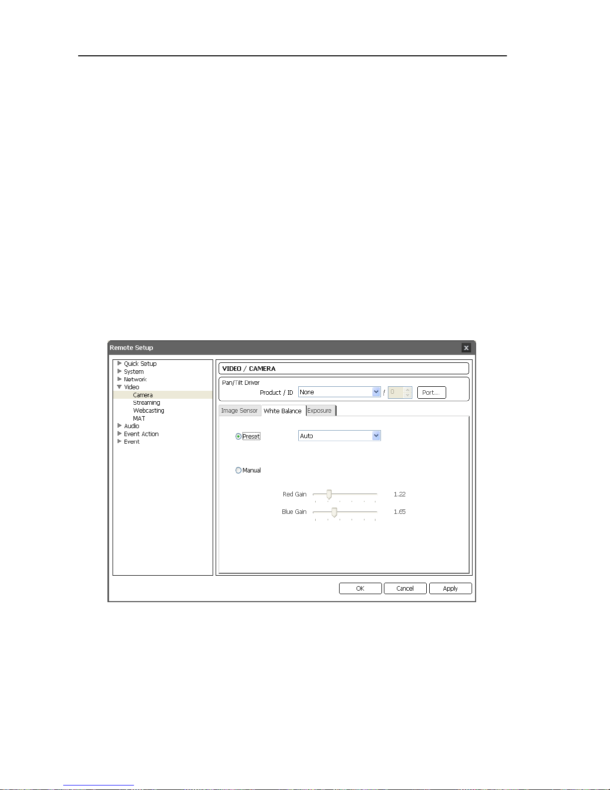
White Balance:
Click the tab to set up white balance settings.
Preset:
Select the preset white balance value based on the conditions.
Auto: Select to adjust the white balance automatically. The system identifies the light source
of where the camera is installed and sets up the proper white balance for the conditions.
INCANDESCENT ~ 9500K: Select the type of light source of where the camera is installed
to set the proper white balance for the conditions.
Manual:
Select to adjust the white balance manually. Adjust the Red and Blue gain. The
higher
the value, the stronger the color is.
Page 29
Network Camera
23
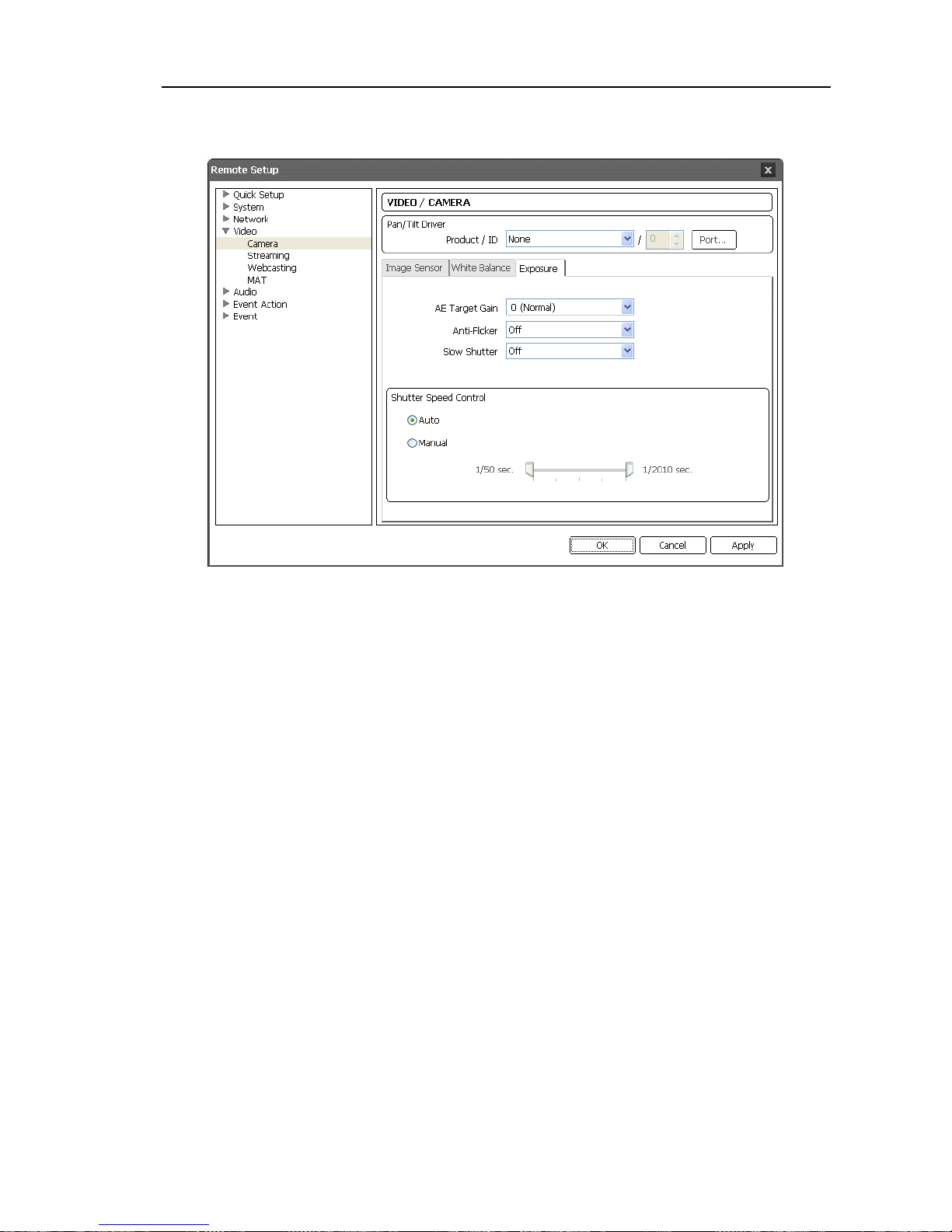
Exposure:
Click the tab to set up exposure settings.
AE
Target Gain:
Set the target gain for the exposure compensation. The camera compensates
the exposure automatically based on the selected target gain. The higher the value is, the
brighter the images are.
Anti-Flicker:
Set to the same frequency as the lighting when the AC power is used for the
lighting such as a fluorescent lights. This reduces video flicker caused by the frequency
differences (60 Hz for NTSC, 50 Hz for PAL).
Slow Shutter:
Set the slow shutter mode. Selecting a speed automatically decreases the
electronic shutter speed during low light conditions so that images are displayed bright
even though the lighting is dim.
Shutter Speed Control:
Set the shutter speed. This is enabled only when both the
Anti-Flicker and Slow Shutter settings are set to Off.
Auto: Select to adjust the shutter speed automatically. The system identifies the light
conditions of where the camera is installed and sets the proper speed for the conditions.
Manual: Select to adjust the shutter speed manually. Adjust the lowest and highest speed
by using slider bars based on the light conditions of where the camera is installed.
NOTE: Selecting Auto for some functions sets up the functions automatically based on
the conditions.
Page 30
User’s Manual
24
Streaming
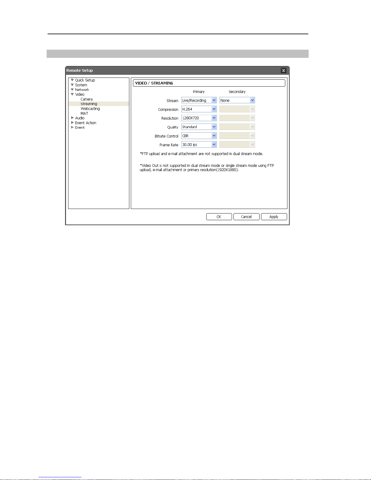
Primary,
Secondary:
The camera supports dual stream video. The secondary stream
setting is dependent on the primary stream setting. In the dual stream mode, the BNC video
out does not work and some event actions (FTP upload and image attachment to Emails)
are disabled.
Stream:
Select the stream usage.
Live/Recording: Allows simultaneous live monitoring and recording. This is supported
only in one of the streams.
Live: Allows live monitoring only.
Compression:
Set up the compression of images for streaming. The primary stream
supports only H.264 compression.
Resolution:
Set the resolution of images for streaming. The resolution supported in the
primary stream varies depending on the camera model. The secondary stream supports
a maximum of 704x480 or 1280x720 resolution depending on the compression, and the
resolution of the secondary stream cannot exceed that of the primary stream. The view
angle of images of the same resolution from the secondary stream might change when
the resolution of the primary stream changes.
352x240: When the resolution of the primary stream is set to this, images are not displayed
in full scale for the BNC video out.
1280x720: Is supported only when the compression of the secondary stream is set to JPEG.
This resolution might not be supported depending on the camera model.
1920x1080: When the resolution of the primary stream is set to this, the secondary stream
supports the JPEG compression and 704x480 resolution only, and the BNC video out
does not work. This resolution might not be supported depending on the camera model.
Quality:
Set up the quality of images for streaming.
Bitrate Control:
Set up the bitrate control mode for the H.264 compression.
CBR (Constant Bitrate): Persists the current bitrate regardless of the amount of motion.
Page 31
Network Camera
25
VBR (Variable Bitrate): Adjusts the bitrate dynamically based on the amount of motion.
The less motion there is, the less network congestion and the less storage capacity. The
quality may not be good comparing to the CBR mode.
Frame Rate:
Set the frame rate of images for streaming. The frame rate of the secondary
stream cannot exceed that of the primary stream, and the frame rates supported for the
secondary stream change depending on the frame rate of the primary stream.
NOTE: Simultaneous connections to the camera might cause the frame rate to decrease
due to the network bandwidth overload.
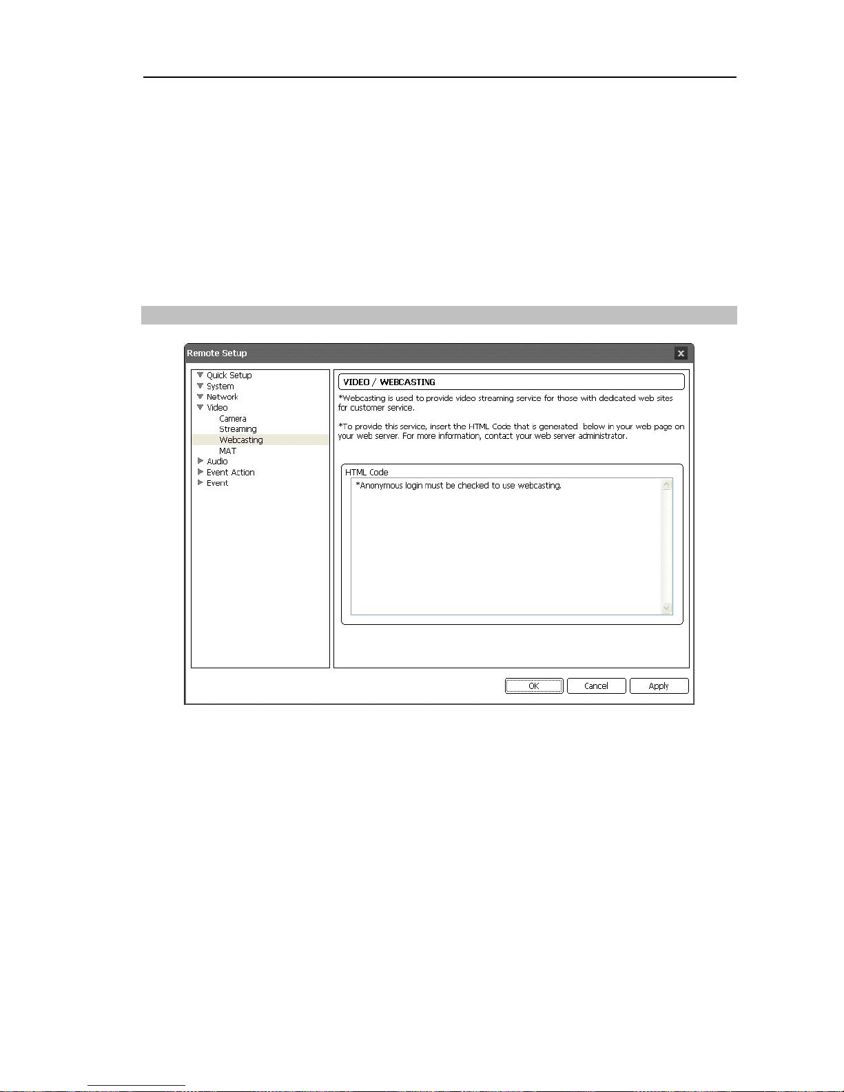
Webcasting
The camera can stream live video from the camera to a website. Copy the HTML Code
displayed on the screen and paste it in your web page code.
NOTE: To use the webcasting service, you must check the Allow Anonymous Login option
during 3.2 System – User/Group setup.
Page 32
User’s Manual
26
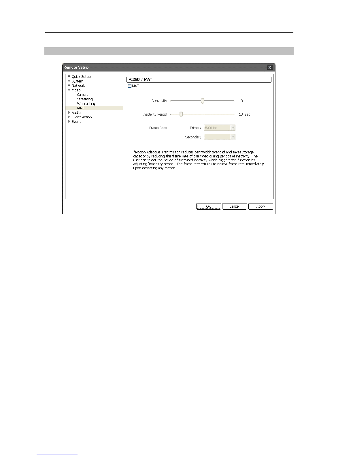
MAT
Check the MAT box to use the MAT (Motion Adaptive Transmission) function for video
streaming and recording. This function is available only when the slow shutter mode is set
to off. Refer to 3.4 Video – Camera (Exposure tab) for details about the slow shutter mode
setting.
Sensitivity:
Set the motion sensitivity. The higher the number is, the more sensitive it is.
Inactivity Period:
Set the inactivity period. The camera will transmit or record images
in Frame Rate set below until any change is detected after the inactivity period when
no motion is detected during the preset inactivity period.
Frame Rate:
Select the frame rate to be applied when no motion is detected. The frame
rate of the secondary stream cannot exceed that of the primary stream, and the frame rates
supported for the secondary stream change depending on the frame rate of the primary
stream. The selected frame rate will be applied until any motion is detected after the
inactivity period and will return to the normal frame rate set during the Stream setup
immediately upon detecting any motion.
NOTE: The MAT (Motion Adaptive Transmission) function allows you to reduce bandwidth
overload and to save storage capacity by reducing the frame rate when no motion is
detected. The camera considers that no motion is detected when no change is detected
between two consecutive images based on the sensitivity setting.
Page 33
Network Camera
27
3.5 Audio
You can set up audio in and out.
I
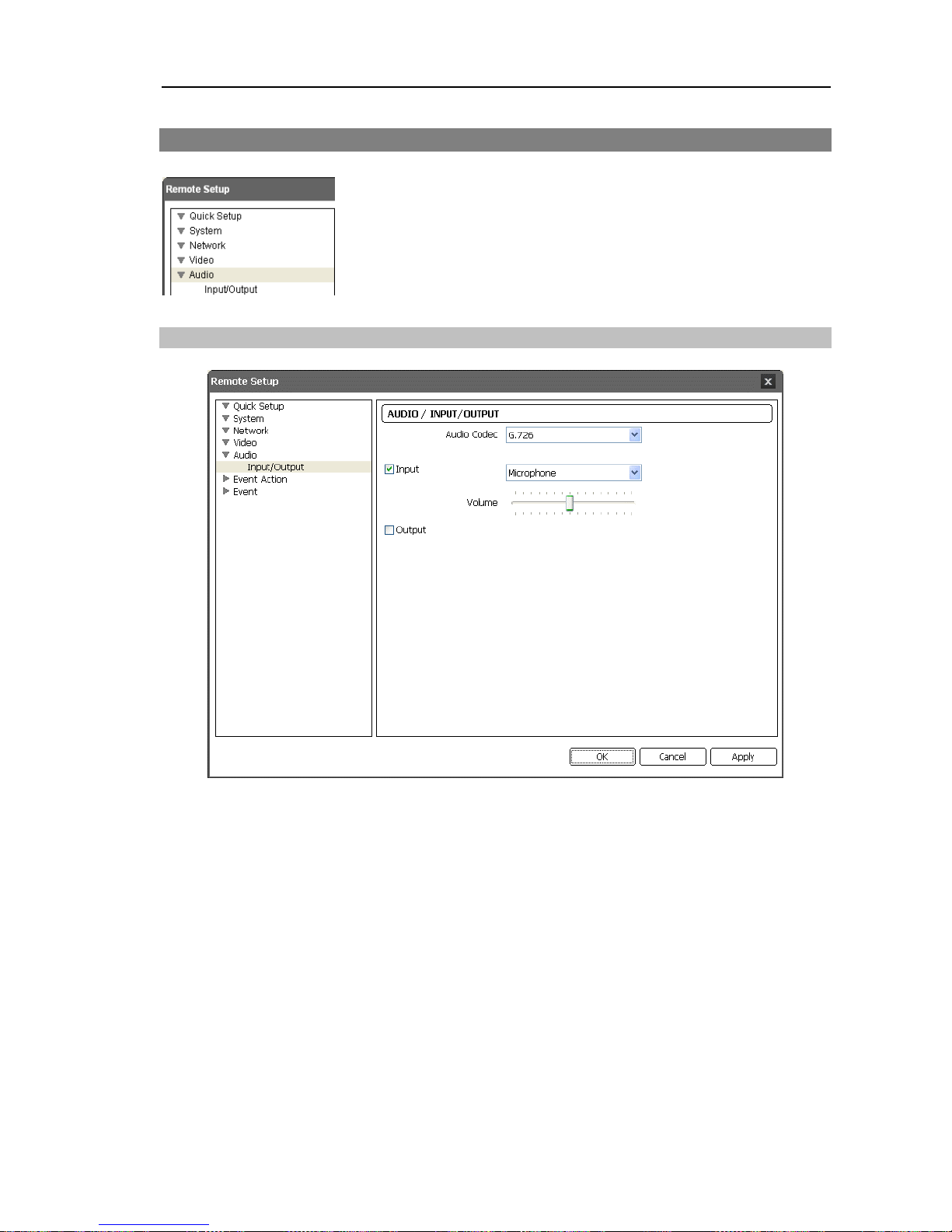
nput/Output
Audio CODEC:
Select an audio codec.
Input:
Check the box to enable audio in and select the proper audio-in device. You can
also adjust the volume.
Output:
Check the box to enable audio out.
NOTE: The camera does not have amplified audio output, so you need to use a speaker
with an amplifier.
Page 34
User’s Manual
28
3.6 Event Action
You can set up event actions to be taken when the camera detects
events.
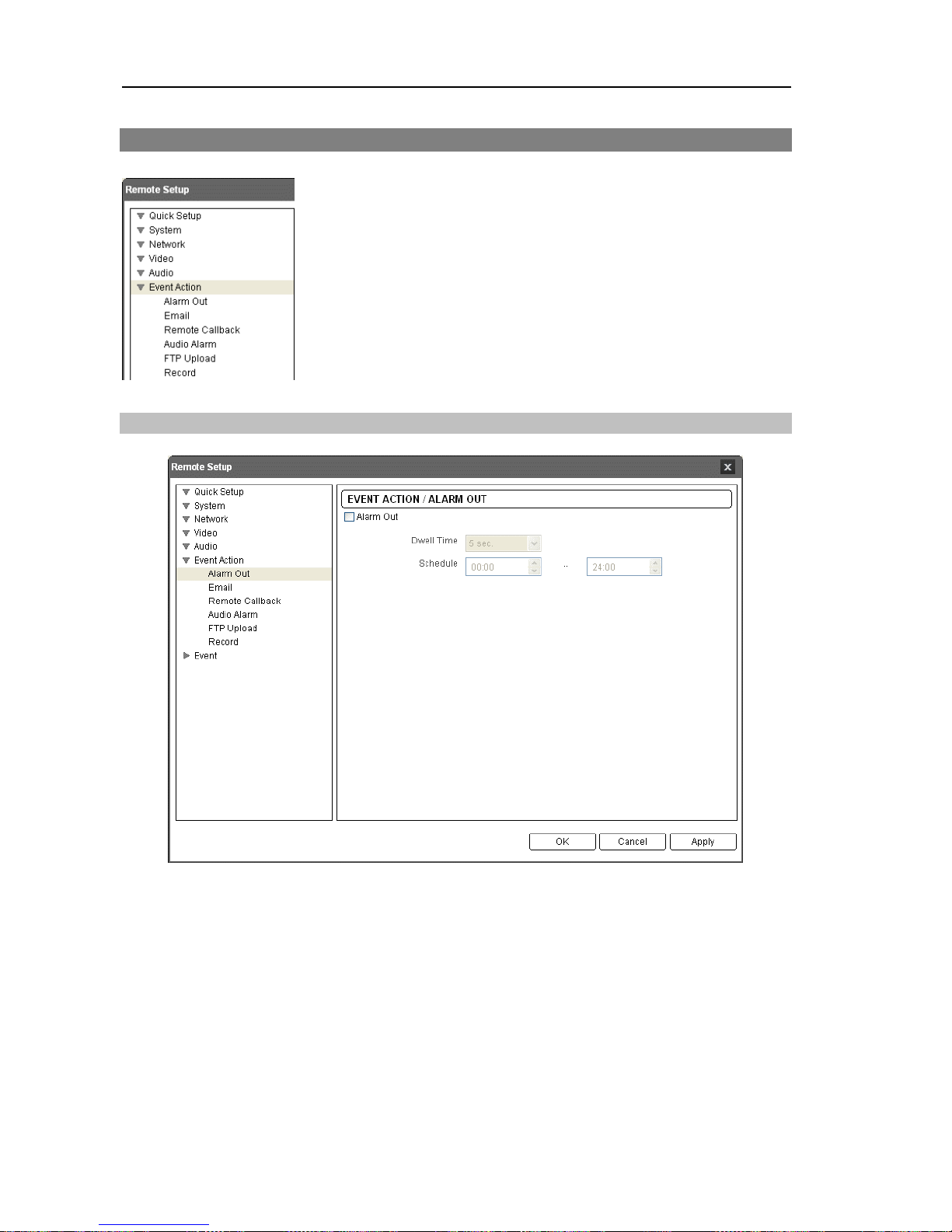
Al
arm Out
Check the Alarm Out box to activate alarm out.
Dwell Time:
Select the alarm-out dwell time. An alarm out is activated for the preset
dwell time after detecting an event.
Schedule:
Set up the period to enable alarm out. An alarm out can be activated only
during this period.
Page 35
Network Camera
29
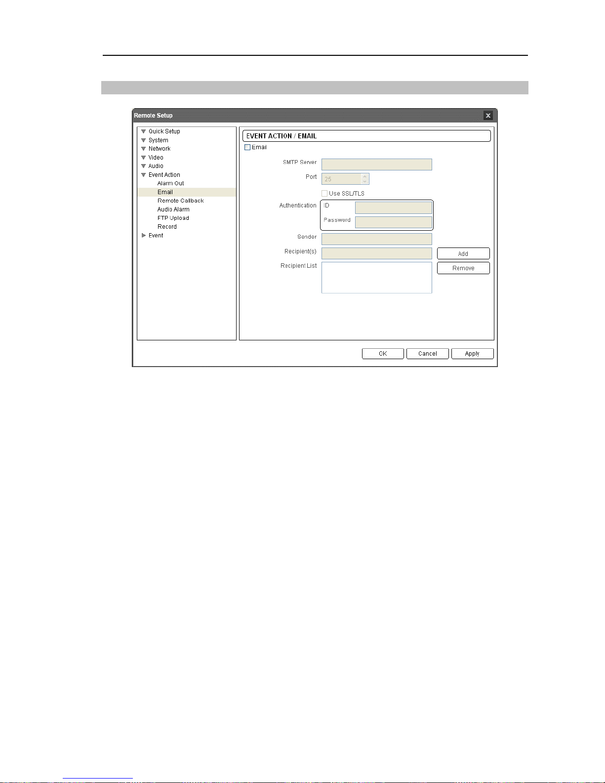
Ema
il
Check the Email box to send an email.
SMTP Server,
Port:
Enter the IP address or domain name and port number of the SMTP
server attained from your network administrator. You can use the domain name instead
of the IP address if you set up the DNS server when setting up the network. Select Use
SSL/TLS if the SMTP server requires SSL (Secure Sockets Layer) authentication.
Authentication:
Enter the ID and password if the SMTP server requires user
authentication.
Sender,
Recipient:
Enter the sender’s and recipients’ (max. 10) email address. An email
address must include the “@” character to be a valid address.
Page 36
User’s Manual
30
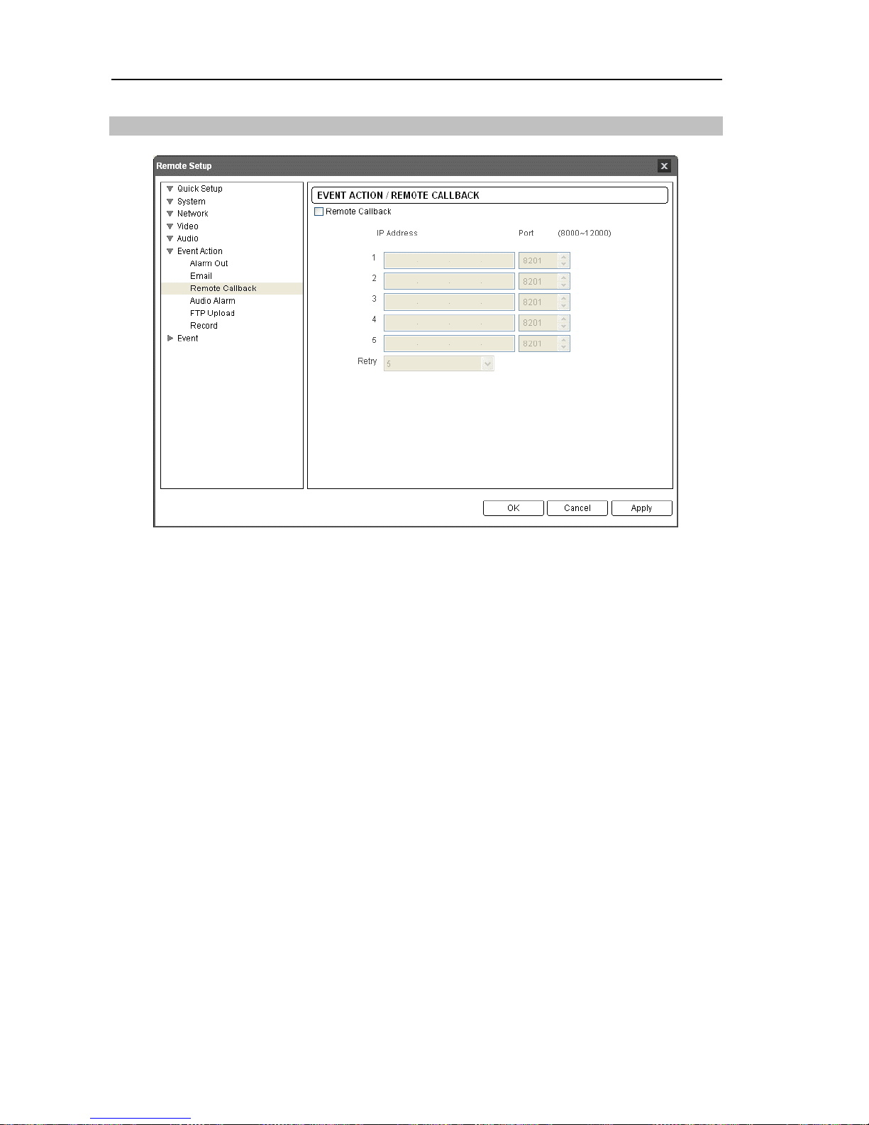
Remote Callback
Check the Remote Callback box to send a callback message to remote systems (Not supported
for the WebGuard program).
IP
Address,
Port:
Enter the IP addresses and port numbers of the remote systems to send
a message.
Retry:
Select the number of times to try sending a message if it fails to send.
Page 37
Network Camera
31
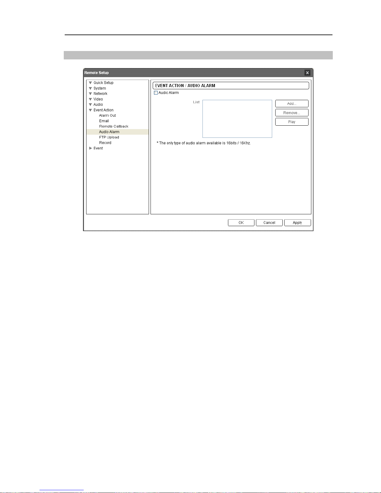
Audio Alarm
Check the Audio Alarm box to sound by playing back an audio file.
List:
Displays the audio file to be played back. You can add or delete an audio file (.wav)
(16 bits/16 KHz encoded file only) by clicking the Add or Remove button. Selecting
an audio file in the list and clicking the Play or Stop button allows you to test the sound
by playing back the selected audio file.
NOTE: Audio files cannot exceed a total of 6MB.
Page 38
User’s Manual
32
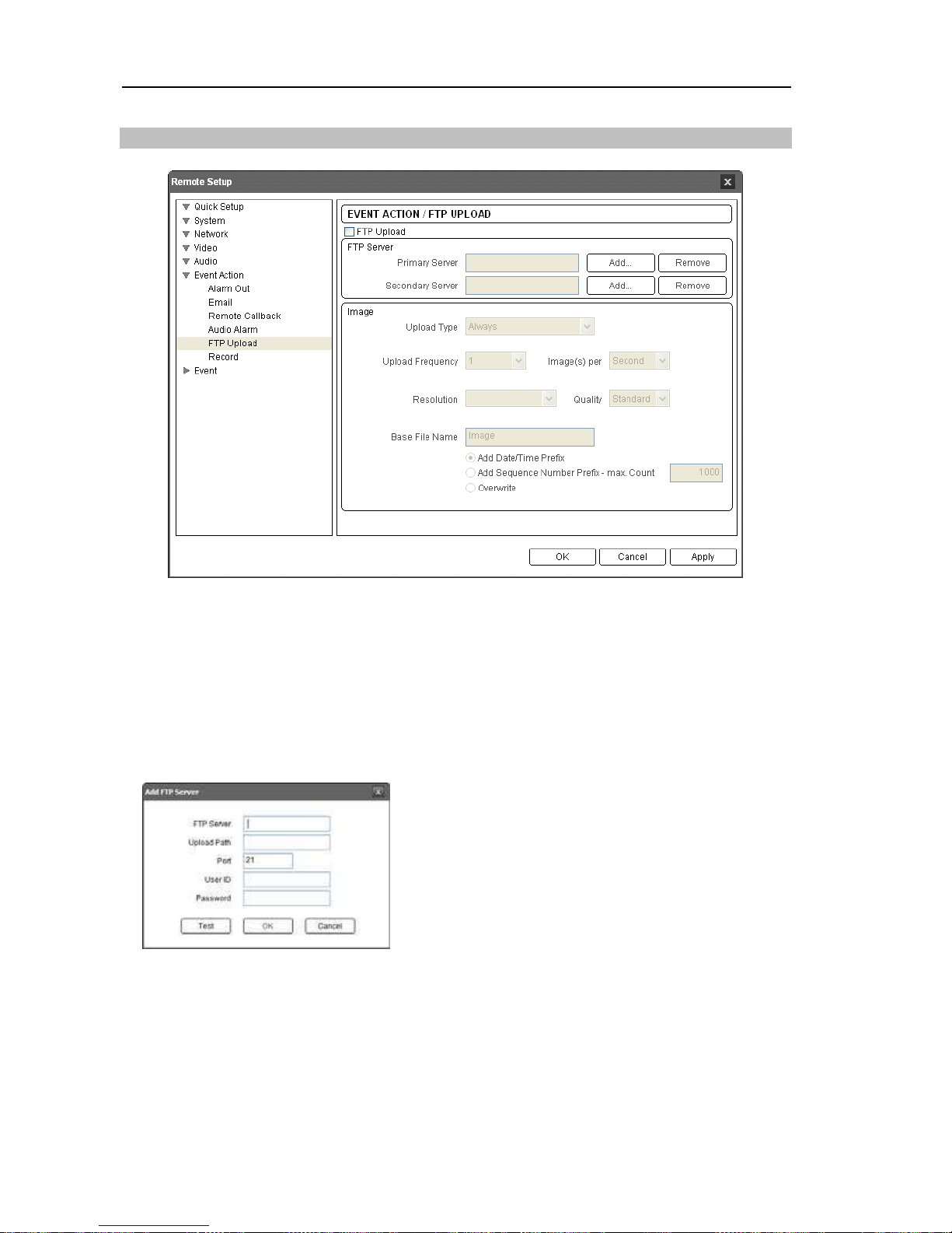
FTP Upload
Check the FTP Upload box to upload event detected images in JPEG file format to an ftp
server.
FTP Server:
Click the Add button to register an ftp server. Clicking the Remove button
deletes the registered ftp server. When an event is detected, the event detected images
will be uploaded in JPEG file format to the ftp server registered as a primary server. If
images fail to be uploaded to the primary server, they are uploaded to the secondary server
until uploading to the secondary server fails.
FTP Server: Enter the IP address (or domain name)
of the ftp server.
Upload Path: Enter the folder path to upload files.
Special characters (\ # * | : " < > ?) cannot be used
in the folder path.
Port: Enter the port number of the ftp server.
User ID, Password: Enter the user ID and password
for the connection to the ftp server.
Click the Test button to check the connection to the ftp server with the information set above.
When the test succeeds, click the OK button.
Image:
Set up the image and upload settings for ftp upload.
Upload Type: Select the upload type. When the upload type is set to Always, images will
be uploaded to the ftp server according to the settings below regardless of the event detection.
When the upload type is set to Event, images will be uploaded to the ftp server according
to the settings below when events are detected.
Page 39
Network Camera
33
Upload Frequency: Displays only when the upload type is set to Always. Set up the upload
rate, and the preset number of images will be uploaded to the ftp server during the preset time.
Upload I image per: Displays only when the upload type is set to Event. Set up the upload
rate. Selecting Upload for allows you to set how long after an event is detected that event
detected images will be uploaded and at what upload rate. Selecting Upload while event
status is active uploads event detected images at the upload rate while an event is detected.
Resolution, Quality: Select the resolution and quality of the images to be uploaded to the
ftp server. The resolution cannot exceed that of the primary stream.
Base File Name: Enter the common file name of the images to be uploaded to the ftp server and
select the option to distinguish each image file. Special characters (\ / # * | : " < > ?) cannot
be used in the file name. Selecting Add Date/Time Prefix adds the event detection date and
time to each image file name. Selecting Add Sequence Number Prefix – max. Count adds
the sequence number according to the event detection order to each image file name.
Selecting Overwrite overwrites the previous image file. The event type is added
to the image file name automatically.
NOTES:
When the FTP Upload function is enabled, the BNC video out does not work.
When in the dual stream mode, the FTP Upload function is disabled.
When the primary stream resolution is set to I920xI080, the video resolution for FTP
upload is fixed at 704x480.
Consider the performance of the FTP server when setting up the upload rate during
the Upload Frequency or Upload 1 image per setting. The FTP upload might fail if the
upload rate exceeds the performance of the FTP server.
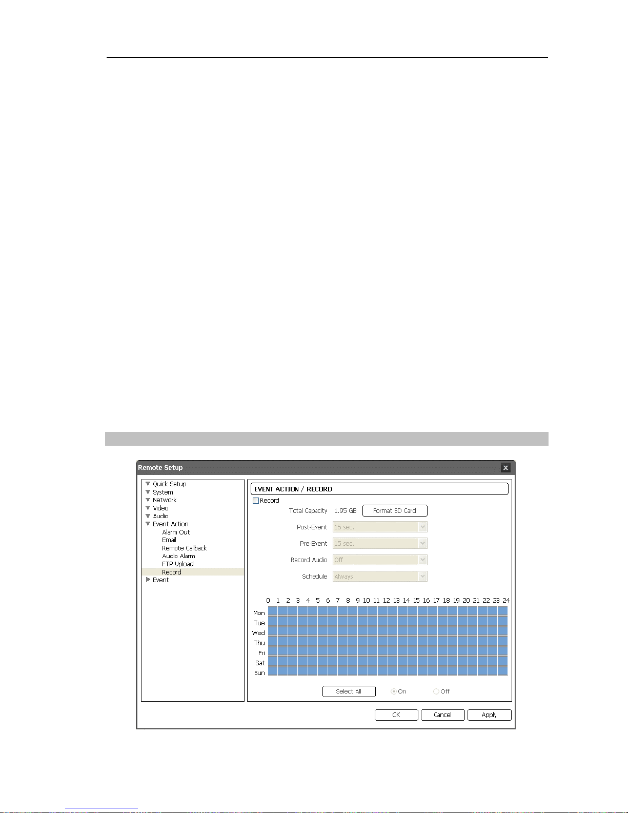
Record
Page 40

User’s Manual
34
Check the Record box to enable recording on an SD memory card when events are detected.
Ensure that the SD memory card (Class 6) is inserted properly.
Total Capacity:
Displays the total capacity of the SD memory card when an SD memory
card is inserted properly.
Format SD Card:
Click the button to format the inserted SD memory card.
Formatting the SD memory card deletes all data saved on the SD memory card. Only
users belonging to the Administrator group can format the SD memory card.
Post-Event:
Select the time span to record video after an event is detected.
Pre-Event:
Select the time span to record video before an event is detected. The camera
can record a maximum of 20 MB of video. If the resolution, quality and frame rate for
recording are set too high and recording capacity during the preset time exceeds 20 MB,
not all video during the time will be recorded.
Audio Record:
Select whether or not to record audio.
Schedule
:
Always: Records video whenever events are detected.
Date/Time: Records video when events are detected during the scheduled date and time
set in the table below. Selecting On or Off and clicking and dragging the desired date and
time area on the schedule table sets up or releases the recording schedule for the selected
date and time. Selecting On or Off and clicking the Select All/Clear All button sets up or
releases the recording schedule for all dates and time.
NOTES:
Searching and playing back video recorded on the SD memory card is supported by
using a remote program. Refer to the User’s Manual for the remote program for details.
Uncheck the Record box before you remove the SD memory card. Removing the SD
memory card while images are being recorded on the SD memory card might cause
damage the system and saved data.
CAUTION: Searching and playing back video recorded on the SD memory card
might not be very smooth when using a remote program while also recording
video on the SD memory card.
3.7 Event
You can set up event detection function.
Page 41
Network Camera
35
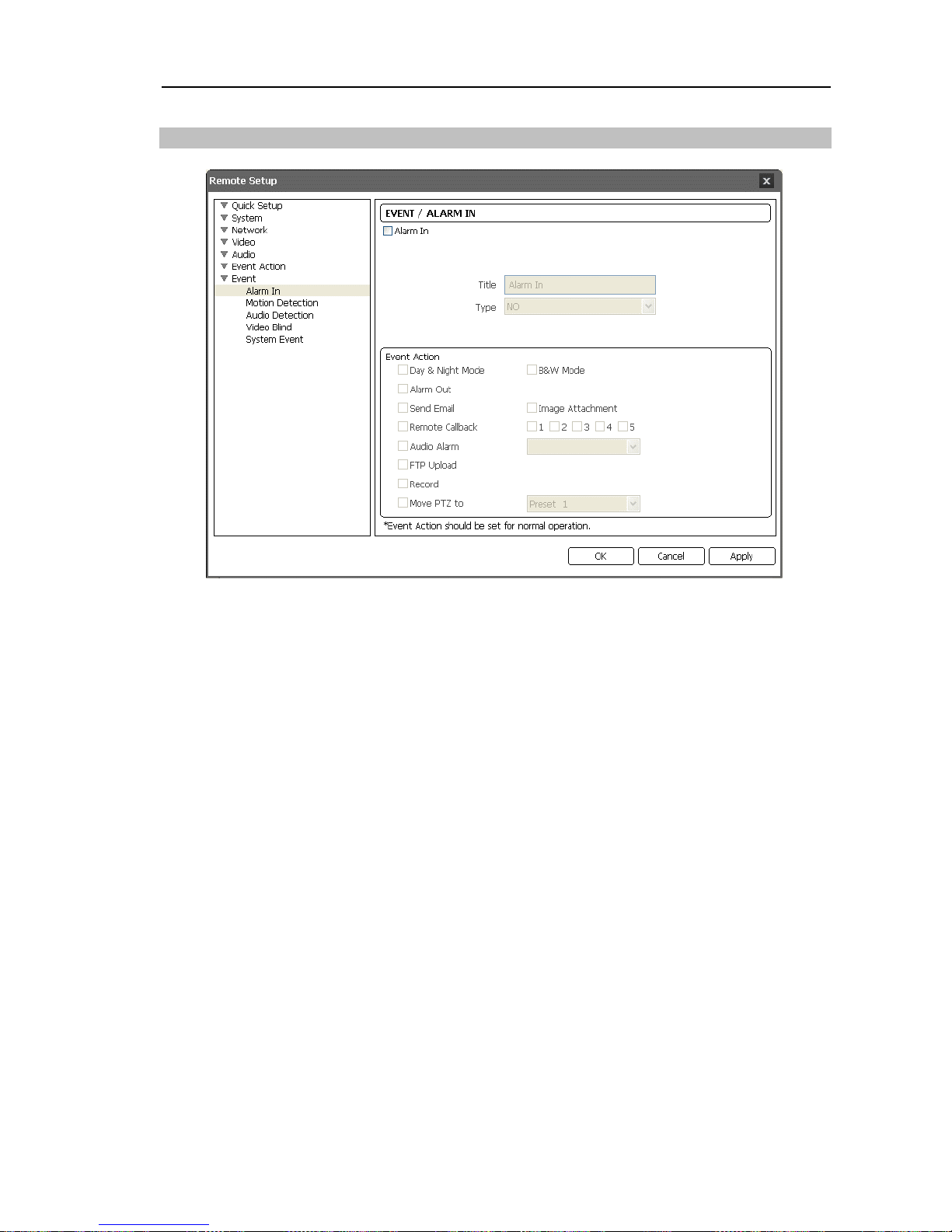
Al
arm In
Check the Alarm In box to set up an alarm-in event. When the camera senses an input on
the alarm input connector, it considers it as an event.
Title:
Enter the alarm-in device’s name.
Type:
Select the alarm-in type.
Event Action:
Check the box for each action the camera will take whenever it detects
an alarm-in event.
Day & Night Mode: Check the box to disable the JR cut filter during the event detection.
Checking the box disables the Day & Night Mode feature set during the Video – Camera
setup. Selecting B&W Mode enables the black and white mode during the event detection.
When the event detection is expired, the JR cut filter is enabled and the black and white
mode is disabled. This feature is available only in models that support the day and night
function.
Alarm Out: Check the box to trigger an alarm-output signal.
Send Email: Check the box to send an email. Selecting Image Attachment attaches an
event detected image file (.JPG) to the email, and the BNC video out is disabled. When in
the dual stream mode, the image attachment option is disabled.
Remote Callback: Check the box and select the remote systems to send a message (Not
supported for the WebGuard program).
Audio Alarm: Check the box and select the audio file (.wav) to sound.
FTP Upload: Check the box to upload images to an ftp server. When in the dual stream
mode, this option is disabled.
Record: Check the box to record video.
Move PTZ to: Select the desired preset number that you want the Pan/Tilt driver to move to.
You must set preset locations for a Pan/Tilt driver using remote programs.
Page 42
User’s Manual
36
NOTE: You must properly configure the settings related to each event action when setting
them up to enable event actions. Refer to 3.6 Event Action.
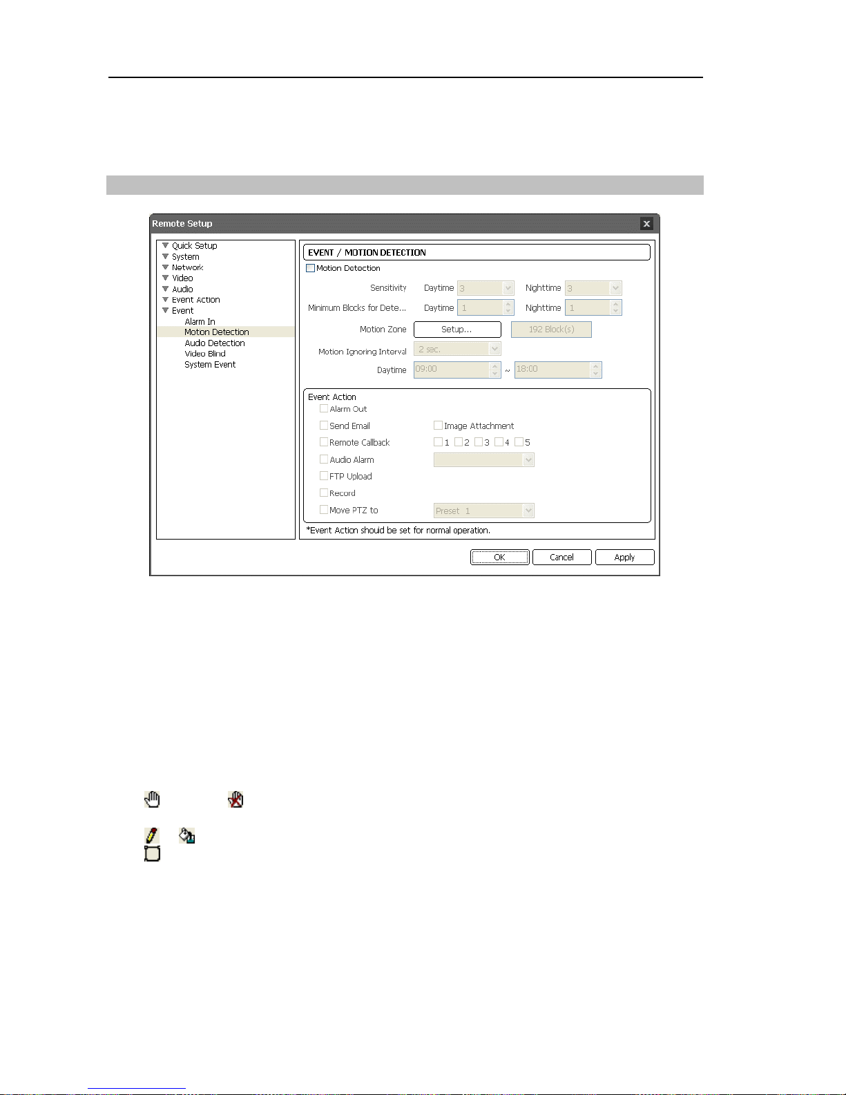
Motion Detection
Check the Motion Detection box to set up a motion detection event. When the camera
detects a motion in a configured motion detection zone, it considers the motion as an event.
Sensitivity:
Set the motion sensitivity for daytime and nighttime independently. The
higher the number is, the more sensitive it is.
Minimum Portion:
Adjust the minimum percentage of detection blocks that must be
activated in order to be considered as a motion event for daytime and nighttime independently.
Motion Zone:
Click the Setup… button and a motion detection zone setup screen appears.
Define the area (max. four) of the image that you want to set up a motion detection zone
by using the motion detection zone icons.
(Select) or (Clear): Click to select or clear a block for motion detection. You can select
or clear the several blocks of an area using the mouse dragging.
or (One or All blocks): Click to select or clear one or all blocks at a time.
(Area): Click to select or clear several blocks of an area.
Motion Ignoring Interval:
Select the motion ignoring dwell time from the drop-down
list. The camera will not log or send notifications of motion events occurring during the
preset interval after a motion is detected. You can control excessive event logging and
remote notifications of motion detection events by adjusting the motion ignoring dwell
intervals.
Daytime:
Set up the daytime range. The camera will consider the remaining time range
as the nighttime.
Page 43
Network Camera
37
Event Action:
Check the box for each action the camera is to take when it detects a motion
detection event.
Alarm Out: Check the box to trigger an alarm-output signal.
Send Email: Check the box to send an email. Selecting Image Attachment attaches an
event detected image file (.JPG) to the email, and the BNC video out is disabled. When in
the dual stream mode, the image attachment option is disabled.
Remote Callback: Check the box and select the remote systems to send a message (Not
supported for the WebGuard program).
Audio Alarm: Check the box and select the audio file (.wav) to sound.
FTP Upload: Check the box to upload images to an ftp server. When in the dual stream
mode, this option is disabled.
Record: Check the box to record video.
Move PTZ to: Select the desired preset number that you want the Pan/Tilt driver to move to.
You must set preset locations for a Pan/Tilt driver using remote programs.
NOTE: You must properly configure the settings related to each event action when setting
them up to enable event actions. Refer to 3.6 Event Action setup.
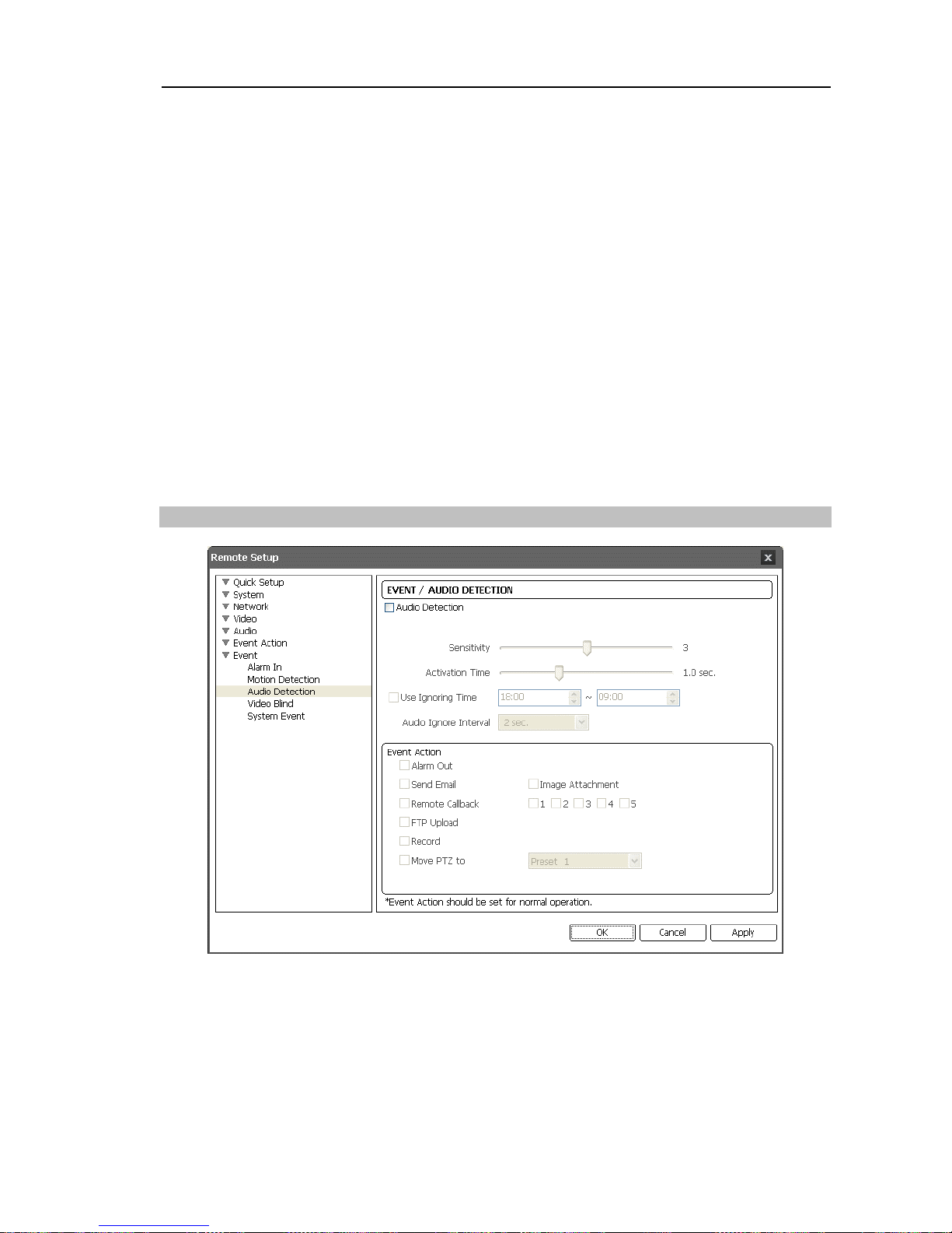
Audio Detection
Check the Audio Detection box to set up an audio detection event. When the camera detects
audio during the preset activation time, it considers it as an event.
Sensitivity:
Set the audio sensitivity. The higher the number is, the more sensitive it is.
Activation Time:
Adjust the duration that audio should last to be considered as an audio-in
event.
The camera will not consider any audio as an audio-in event if it lasts less than
the preset time.
Page 44
User’s Manual
38
Use Ignoring Time:
Set up the event ignoring time. The camera will not consider audio
that occurs during the preset time span as an event.
Audio Ignoring Interval:
Select the audio ignoring dwell time from the drop-down list.
The camera will not log or send notifications of audio events occurring during the preset
interval after an audio is detected. You can control excessive event logging and remote
notifications of audio detection events by adjusting the audio ignoring dwell intervals.
Event Action:
Check the box for each action the camera is to take when it detects an
audio-in event.
Alarm Out: Check the box to trigger an alarm-output signal.
Send Email: Check the box to send an email. Selecting Image Attachment attaches an
event detected image file (.JPG) to the email, and the BNC video out is disabled. When in
the dual stream mode, the image attachment option is disabled.
Remote Callback: Check the box and select the remote systems to send a message (Not
supported for the WebGuard program).
FTP Upload: Check the box to upload images to an ftp server. When in the dual stream
mode, this option is disabled.
Record: Check the box to record video.
Move PTZ to: Select the desired preset number that you want the Pan/Tilt driver to move to.
You must set preset locations for a Pan/Tilt driver using remote programs.
NOTE: You must properly configure the settings related to each event action when setting
them up to enable event actions. Refer to 3.6 Event Action.
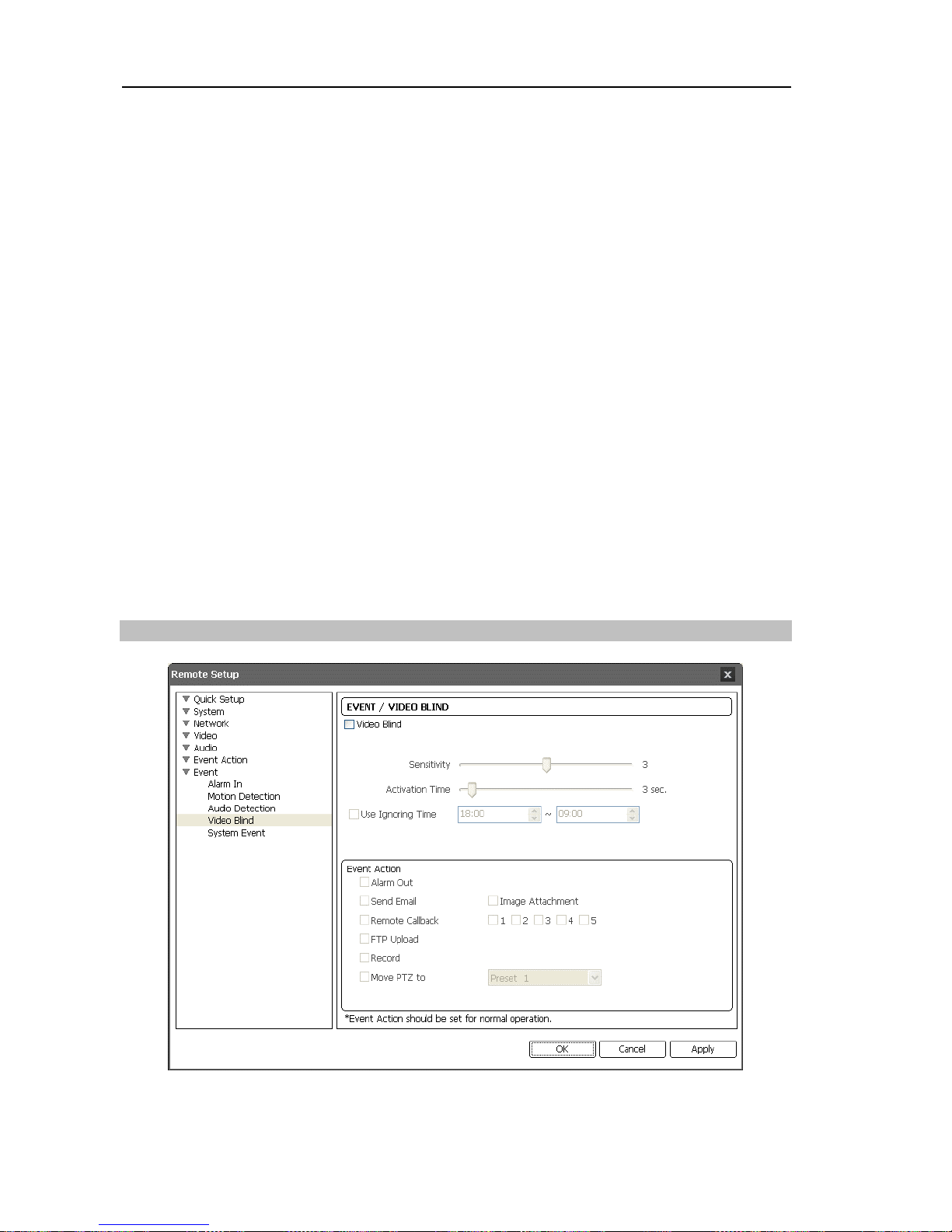
Vi
deo Blind
Check the Video Blind box to set up a video blind event. When the camera detects that
more than 70% of a camera is blinded by anything, it considers the video blind as an event.
Page 45

Network Camera
39
Sensitivity:
Adjust the sensitivity for the video blind. The higher the number is, the more
sensitive it is.
Activation Time:
Adjust the duration that a video blind should last to be considered a
video blind event. The camera will not consider any video blind as a video blind event
if it is shorter than the preset time.
Use Ignoring Time:
Set up the event ignoring time. The camera will not consider a
video blind that occurs during the preset time span as an event.
Event Action:
Check the box for each action the camera will take whenever it detects
a video blind event.
Alarm Out: Check the box to trigger an alarm-output signal.
Send Email: Check the box to send an email. Selecting Image Attachment attaches an
event detected image file (.JPG) to the email, and the BNC video out is disabled. When in
the dual stream mode, the image attachment option is disabled.
Remote Callback: Check the box and select the remote systems to send a message (Not
supported for the WebGuard program).
FTP Upload: Check the box to upload images to an ftp server. When in the dual stream
mode, this option is disabled.
Record: Check the box to record video.
Move PTZ to: Select the desired preset number that you want the Pan/Tilt driver to move to.
You must set preset locations for a Pan/Tilt driver using remote programs.
NOTES:
Video blind events might NOT be detected for a camera with a very noisy image especially
when set for low Sensitivity values.
You must properly configure the settings related to each event action when setting
them up to enable event actions. Refer to 3.6 Event Action.
Page 46
User’s Manual
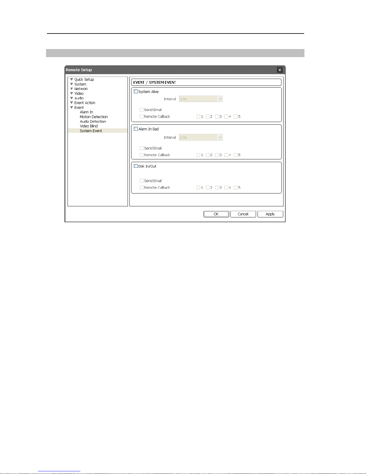
System Event
Check the System Event box to set up a system event. The camera checks and reports the
system and alarm-in status and SD memory card on or off.
System Alive Message:
Check the box to check the system operation, and select the
check interval.
Send Email: Check the box to send an email when the system is operating.
Remote Callback: Check the box and select the remote systems to send a message when
the system is operating (Not supported for the WebGuard program).
Alarm In Bad Message:
Check the box to check the alarm-in operation and select the
check interval.
Send Email: Check the box to send an email when there is no change of alarm-in event status.
Remote Callback: Check the box and select the remote systems to send a message when
there is no change of alarm-in event status (Not supported for the WebGuard program).
Disk In/Out:
Check the box to send notices if an SD memory card is inserted or removed.
Send Email: Check the box to send an email when the SD memory card is inserted to or
removed from the camera.
Remote Callback: Check the box and select the remote systems to send a message when
the SD memory card is inserted to or removed from the camera (Not supported for the
WebGuard program).
NOTE: You must properly configure the Email and Remote Callback settings when
setting them up to send an email or a message. Refer to 3.6 Event Action
.
40
Page 47
Network Camera
Chapter 4 — WebGuard
You can monitor live video images from the camera or search recorded image saved in the
SD memory card on the web browser by using the WebGuard program.
Computer system requirements for using WebGuard are:
Operating System: Microsoft® Windows® XP x86 (32 Bit) (Service Pack 3), Microsoft
®
Windows® Vista x86 (32 Bit) (Service Pack 1) or Microsoft® Windows® 7 x86 (32 Bit)
CPU: Intel Pentium III (Celeron) 600MHz or faster (Core 2 Duo E4600 recommended)
RAM: 128MB or more (2GB recommended)
VGA: 8MB or more (128MB recommended) (1024x768, 24bpp or higher)
Internet Explorer:
Version 6.0 or later
Start Internet Explorer on your local PC. You can run the WebGuard program by entering
the following information in the address field.
“http://IP address:port number” (The camera IP address and the WebGuard port number set
during the port setup)
Or, “http://DVRNS server address/camera name” (The DVRNS server address and the camera
name registered on the DVRNS server)
NOTES:
Enter https instead of http if you have checked the Use HTTPS box during the WebGuard
port number setup. Click Continue to this website (not recommended) when the security
certificate warning page is displayed. When the WebGuard login page is not displayed,
check Internet option settings as follows:
– Go to Tools, then Internet Options, and then the Security tab ! Click the Custom level…
button ! Set the setting of Reset custom settings to Medium-high (default) or Medium.
– Go to Tools, then Internet Options, and then the Advanced tab ! Check the Use TLS
1.0 box under the Security option.
You do not need to enter the WebGuard port number if the WebGuard port number is
set to 80 (443 when entering https) when running the WebGuard program by entering
the IP address and port number.
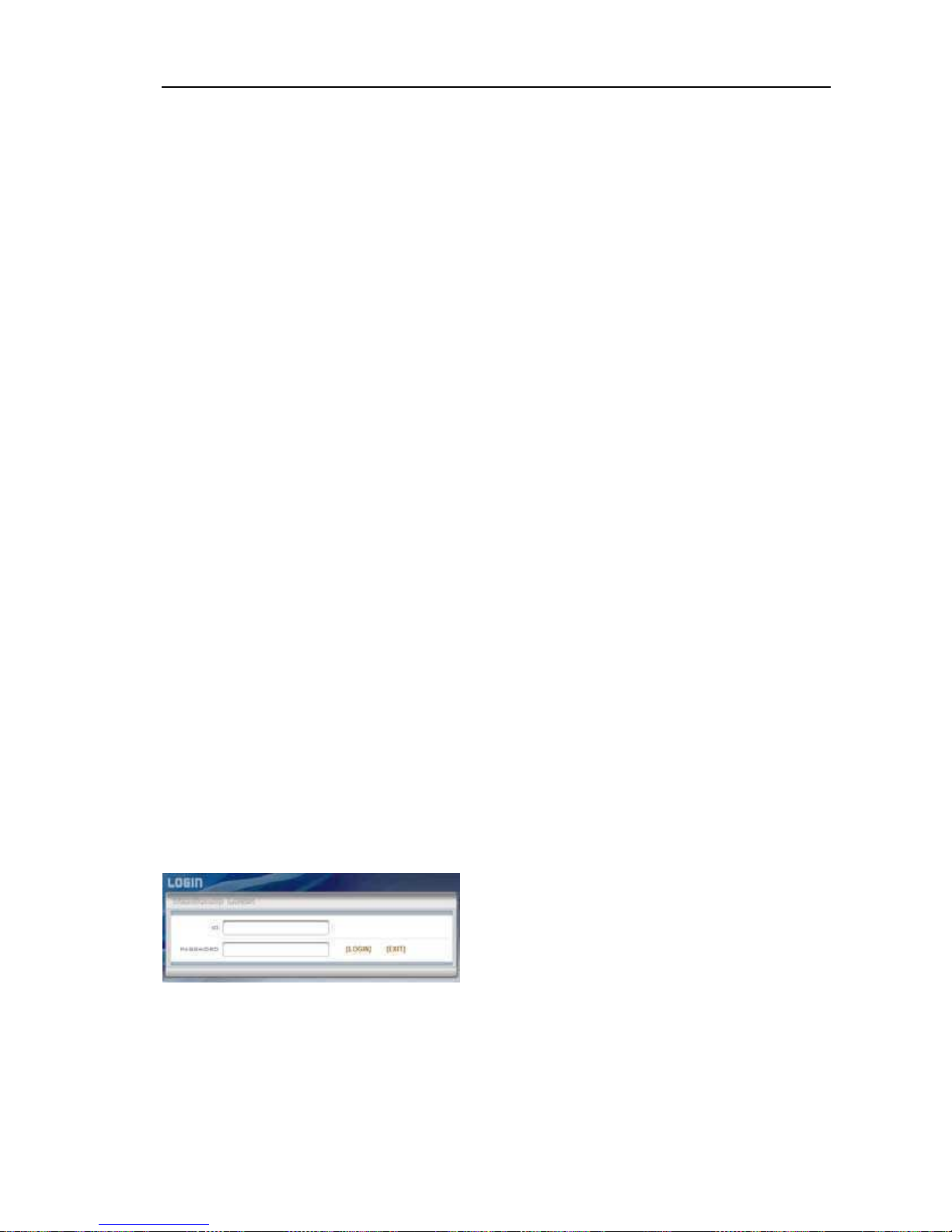
Enter your ID and PASSWORD and click the
[LOGIN] button.
NOTES:
WebGuard only works with Microsoft Internet Explorer and will NOT work with other
web browsers.
Do NOT close the LOGIN window during the WebGuard operation, otherwise, it will
cause a script error when switching between Web monitoring and Web search modes,
and you will need to restart the WebGuard program.
4I
Page 48

User’s Manual
42
NOTES:
There might be a problem with the bottom of the WebGuard page being cropped caused
by the address or status bars in Microsoft Internet Explorer 7.0. In this situation, it is
recommended that websites open windows without address or status bars by changing
Internet setting. (Go to Tools, and Internet Options, and then the Security tab ! Click
the Custom level… button ! Select Enable for the Allow websites to open windows
without address or status bars option.)
When running WebGuard in the Microsoft® Windows® Vista or later operating system, it
is recommended that you start Internet Explorer with elevated administrator permissions.
Click the right mouse button on the Internet Explorer icon and select the Run as
administrator option from the context menu. Otherwise, some functions of WebGuard
might be limited.
There might be a problem with screen display or screen update caused by low image
transmission speed when using the Microsoft® Windows® Vista or later operating system.
In this situation, it is recommended that you disable the Auto Tuning capability of your
computer. Run the Command Prompt with elevated administrator permissions (Go
to the Start Menu, and Accessories, and then Command Prompt ! Click the right
mouse button and select the Run as administrator option). Then enter “netsh int tcp
set global autotuninglevel=disable” and press the enter key. Restart your computer
to apply the changes. If you want to enable the Auto Tuning capability again, enter
“netsh int tcp set global autotuninglevel=normal” after running the Command Prompt
with elevated administrator permissions. Restart your computer to apply the changes.
When running the updated WebGuard for the first time, Internet Explorer might occasionally
load the information from the previous version. In this case, delete the temporary Internet
files by selecting Tools ! Internet Options ! General tab, and then run WebGuard again.
You will need to get the appropriate IP address for the camera you want to connect
to and the WebGuard port number from your network administrator.
Page 49
Network Camera
43
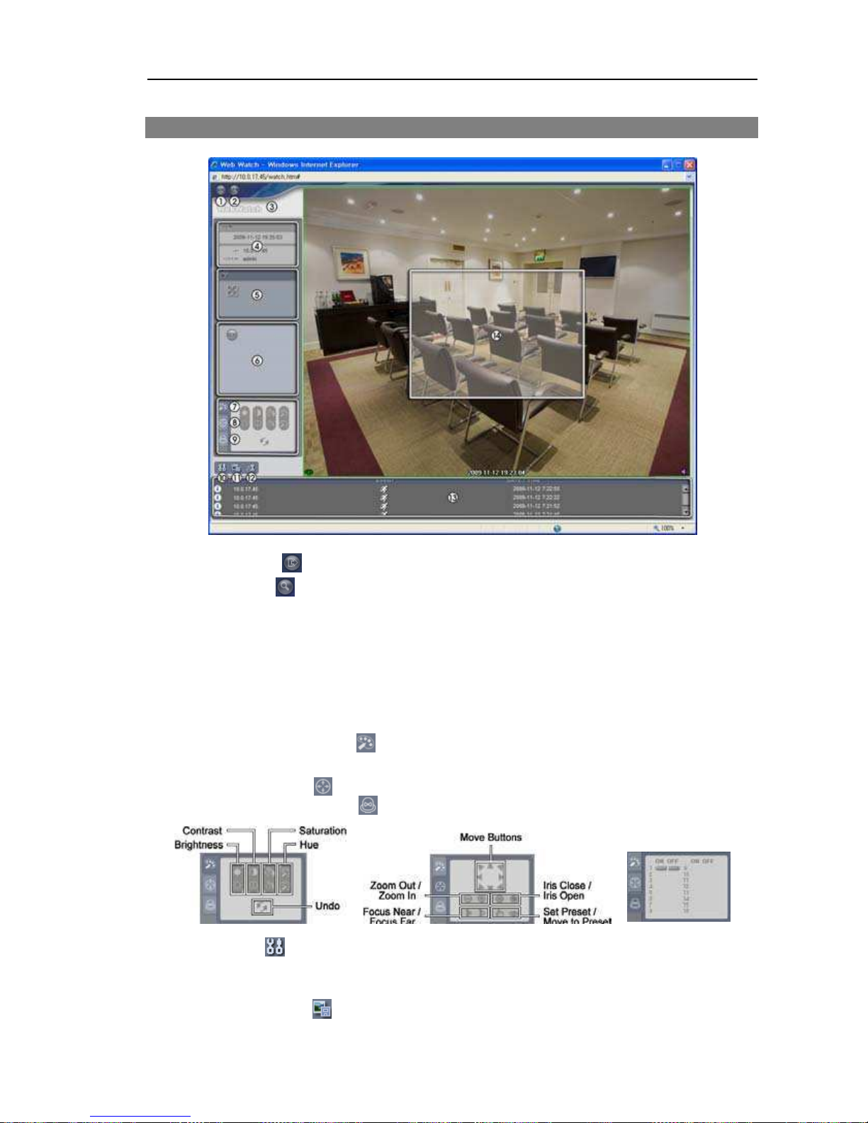
Web Monitoring Mode
Log Out:
Click
to
log out of the WebGuard program.
Search:
Click
to
access to the web search mode.
Version:
Position the mouse pointer on the WebWatch logo to see the WebGuard program
version.
Information:
The Information window displays the login information of WebGuard.
Full Display:
Clicking the button displays the video in full screen. Pressing the Esc
button on a keyboard returns to the previous screen.
Camera Button:
The button displays the camera number.
Image Adjustment:
Click
to
adjust the brightness, contrast, saturation and hue of
monitored image.
PTZ Control:
Click
to
control pan and tilt of the Pan/Tilt driver remotely.
Alarm-Out Control:
Click
to
control an alarm out device remotely.
Setup:
Click
to
set up the image drawing mode and OSD display. You can adjust
the display speed by changing the image drawing mode, and select OSD information
to be displayed on the screen.
Save Image:
Click
to
save the current image as a bitmap or JPEG file format.
Page 50
User’s Manual
44
Remote Setup:
Click
to
change the settings of the camera by using the Remote
Setup screen.
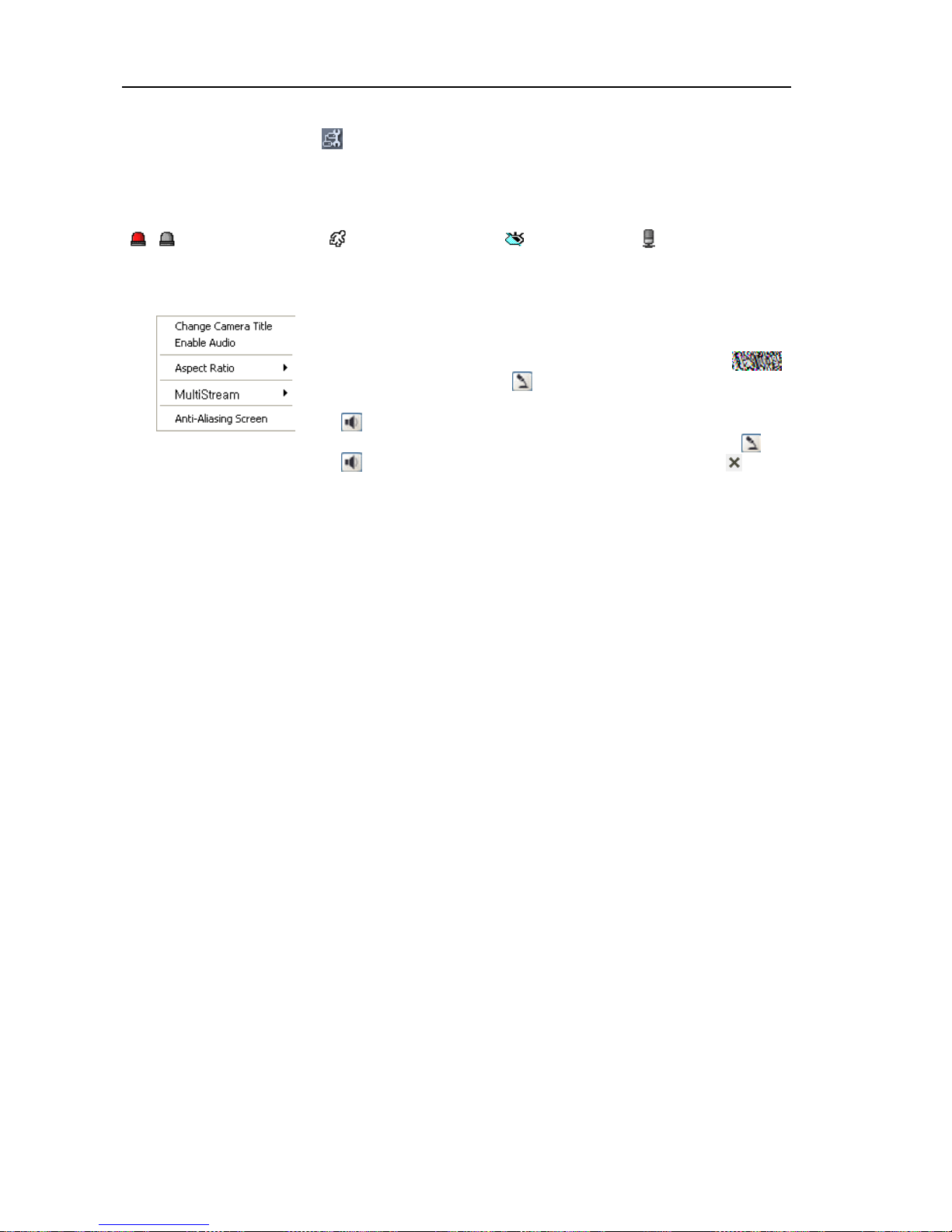
Event Status Window:
The event status window at the bottom displays a list of events that
were detected in the camera.
/
Alarm In On/Off Motion Detection Video Blind Audio Detection
Screen Popup Menu:
Clicking the right mouse button on the screen displays the screen
popup menu.
Change Camera Title: Select to change the camera title.
Enable Audio: Select to enable audio communication with the
site which the camera is installed and the audio control
panel appears. Click the button to send audio to the site which
the camera is installed and speak into the microphone. Click the
button to monitor live audio from the site which the camera is
installed through the attached speaker. Clicking both the and
buttons allows two-way communication. Clicking the button
disables audio communication.
Aspect Ratio: Select to change the image aspect ratio displayed on the screen and the
option menu appears. Selecting Fit to Screen displays images by fitting them to the screen
size. Selecting Original Ratio displays images by fitting them to the screen size while
maintaining their original ratio. Selecting Half Size (x0.5) to Quadruple Size (x4) displays
the images at the selected image size.
Multistream: Select to choose the desired stream if the camera is in dual stream mode.
Anti-Aliasing Screen: Select to enhance image display quality by eliminating stair stepping
(aliasing) effects in the enlarged image.
NOTES:
The image adjustment for the monitoring screen works only in the pause mode.
A camera name change in the Web Watch mode does not affect the camera name set
up on the camera. Leaving the Camera Title blank causes the camera name set up
on the camera to display.
Aspect Ratio – Half Size (x0.5) to Aspect Ratio to Quadruple Size (x4) in the Screen
Popup Menu will be enabled when the selected camera screen can display images
in those sizes.
Page 51
Network Camera
45
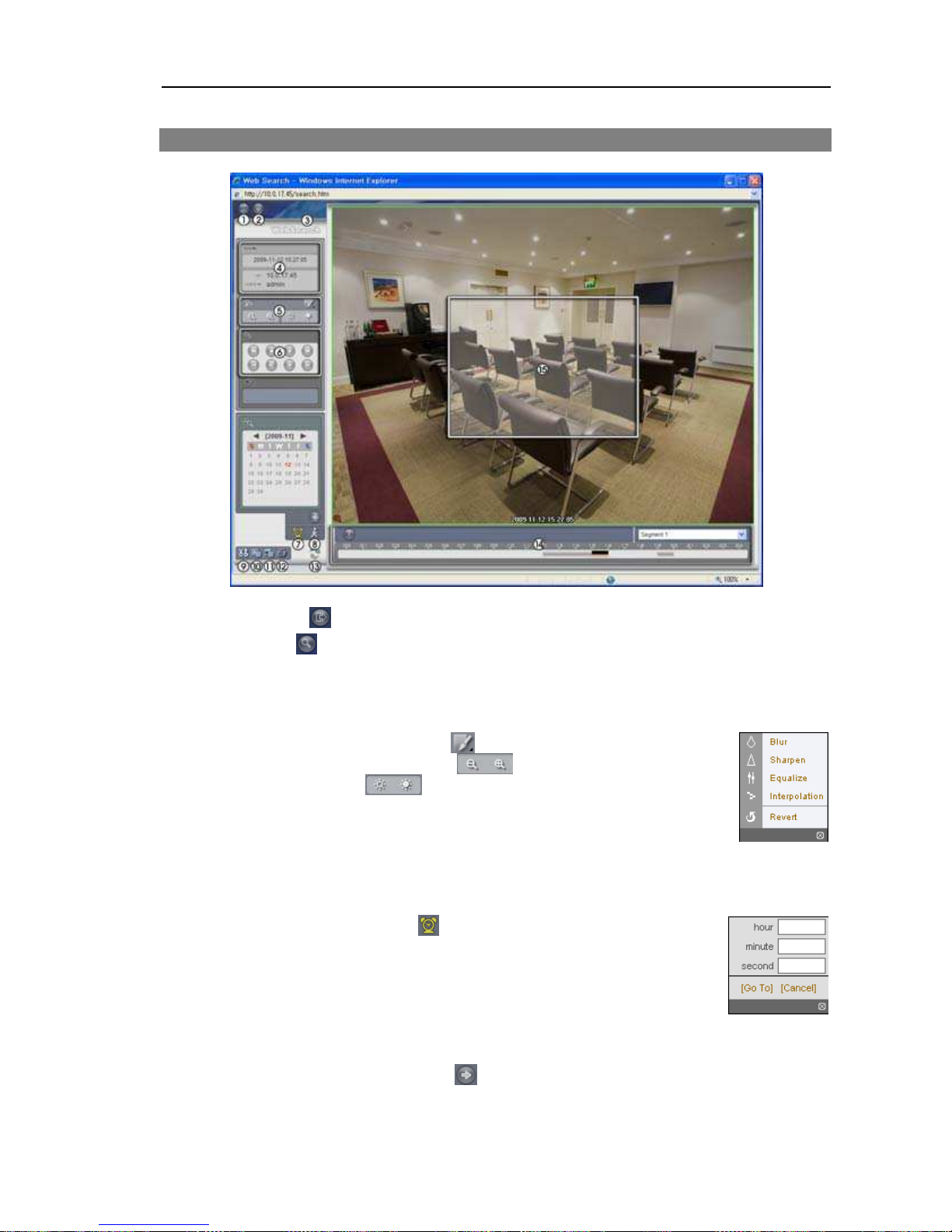
Web Search Mode
Log Out:
Click
to
log out of the WebGuard program.
Watch:
Click
to
access to the web monitoring mode.
Version:
Position the mouse pointer on the WebSearch logo to see the WebGuard program
version.
Information:
Displays the login information of WebGuard.
Playback Image Control:
Click
to blur, sharpen, equalize and
interpolate playback images. Click
to zoom out or zoom in the
recorded image. Click
to
adjust the brightness of the recorded
images.
NOTE: Image processing works only in the pause mode.
Playback Control:
Click the desired button to play recorded video. The following
functions are supported: fast backward, pause, play, fast forward, go to the first image,
go to the previous image, go to the next image, and got to the last image.
Time-Lapse Search:
Click
to
enter the time-lapse search mode
which allows you to search for recorded data by time and then play
back images found within the time parameters. The Timetable window
located at the bottom displays the time information for the image of the
date selected on the calendar. If the camera has more than one video
segment in the same time range, you can select the video segment you
want to search. Clicking a specific time displays the image recorded
at that time on the screen. Selecting
allows you to display an image
from a specific time.
Page 52
User’s Manual
46
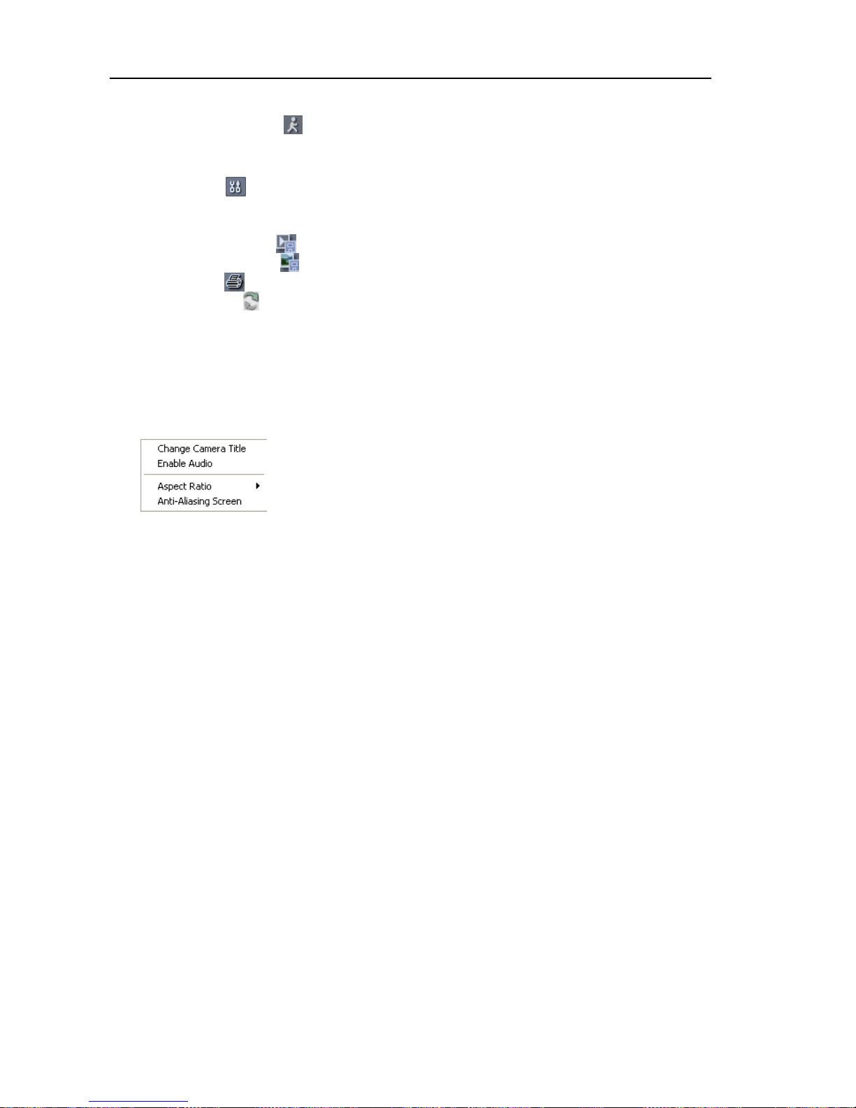
Event Search:
Click
to
enter the event search mode which allows you to search
for event log entries using specific conditions and play back the images associated with
those event entries.
Setup:
Click
to
set up the image drawing mode and OSD display. You can adjust
the display speed by changing the image drawing mode, and select OSD information
to be displayed on the screen.
Save Video:
Click
to save any video clip of recorded data as a video file.
Save Image:
Click
to save the current image in a bitmap or JPEG file format.
Print:
Click
to print the current image on a printer connected to your computer.
Reload:
Click
to reload the recording data.
Timetable:
Displays recorded data of the camera by time (in hour segments). If the
camera’s time and date have been reset to a time that is earlier than some recorded video
and more than one video segment exists in the same time range, select the video segment
you want to search from the SEGMENT menu at the top-right corner on the timetable.
Screen Popup Menu:
Clicking the right mouse button on the screen displays the screen
popup menu.
Change Camera Title: Select to change the camera title.
Enable Audio: Plays audio while playing back recorded video
that has recorded audio.
Aspect Ratio: Changes the image aspect ratio.
Anti-Aliasing Screen: Select to enhance image display quality
by eliminating stair stepping (aliasing) effects in the enlarged image.
NOTE: A camera name change in the Web Search mode does not affect the camera name
set up on the camera. Leaving the Camera Title blank causes the camera name set up
on the camera to display.
Page 53
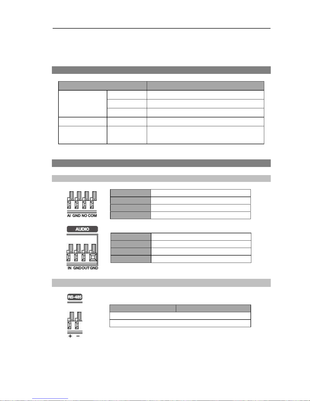
Network Camera
47
AI
Alarm Input
GND
GND (Chassis Ground)
NO
Alarm Out (Normally Open)
COM
Common
IN
Audio Input
GND
GND (Chassis Ground)
OUT
Audio Out
GND
GND (Chassis Ground)
Master Unit
Slave Unit
+
— To
—
TX+/RX+
–
— To —
TX-/RX-
Appendix
LED Indicators
LED Status
Description
Unlit
No power connected to the unit.
Flicker
The unit is booting.
Power LED
Lit
The unit is operating.
Network LED
Lit
The unit is connected to a network.
Power LED &
Network LED
Flicker
sequentially
The unit is upgrading the software.
Connector Pin Outs
I/O
Connector
RS485 Connector
Page 54
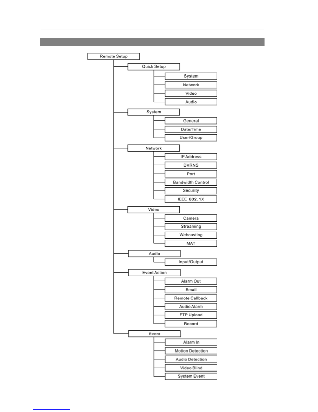
User’s Manual
48
Map of Screens (Remote Setup)
Page 55

Network Camera
49
Troubleshooting
Problem
Possible Solution
No Power
Check power cord connections.
Confirm that there is power at the outlet.
PoE switch is not
recognized.
Check the ground status of the PoE switch and the connected
input/output devices to the camera. If they are not grounded,
use them after grounding.
No Live Video
Confirm that the camera has power.
Check that the lens cap has been removed.
Check that the lens iris is open when using a manual iris
lens, or check that the auto iris jack and its connection when
using a DC-type auto iris lens is attached.
Check network connections on your PC and a camera.
Live video is not clear.
Check if there is dust or dirt on the lens and clean the lens
with a clean cotton cloth or brush.
Check that the focus is set correctly.
Check that the lighting and adjust the camera position or
angle if bright light is shining directly into the lens.
Video color appears
incorrect.
Check that the white balance setting for the camera. When
set to Auto, it
might take awhile to adjust the white balance.
Video flickers.
Check to see if the camera points directly at the sun or a
fluorescent light and adjust the camera’s direction.
Check that the auto iris jack and its connection when using
a DC-type auto iris lens.
Connection to the INIT
program is not available
because of wrong ID and
password.
If you lost the administrator ID and password, do a factory
reset and customize all settings all over again. The factory
reset returns all the settings including network settings to the
original factory settings. Write down the password just in case.
The WebGuard program
is not available.
If you cannot launch the login page of the WebGuard program,
check Microsoft Internet Explorer’s version. WebGuard might
not run properly in versions earlier than 6.0.
Page 56

User’s Manual
Specifications
CAMERA
Image Sensor
1/2.7" CMOS
Lens
(Optional)
Manual iris, DC-type auto-iris (mega pixel recommended)
Lens
Mount
CS, C mount
Minimum Illumination 0.5 Lux @ F 1.4 (color)
Scanning Mode
Progressive scan
SNR
45 dB
Wide Dynamic Range
100 dB
Day/Night Filter
Yes
Electronic Shutter
Auto
External Storage
(Optional)
SD (SDHC) memory card (class 6, max. 32GB)
VIDEO
Video Signal
NTSC or PAL (programmable)
Compression Algorithm H.264, M-JPEG (Four levels)
Compression Resolution
D1 models: 352x240, 704x480
HD models: 352x240, 704x480, 1280x720
Full HD models: 352x240, 704x480, 1280x720, 1920x1080
Bitrate Control
H.264
CBR (up to 12 Mbps) / VBR (varied by each model)
Maximum Frame Rate
(images per second)
D1 models: 30 ips + 30 ips @ 704x480 for NTSC
25 ips + 25 ips @ 704x480 for PAL
HD models: 30 ips @ 1280x720 + 30 ips @ 704x480 for NTSC
25 ips @ 1280x720 + 25 ips @ 704x480 for PAL
Full HD models:
30 ips @ 1280x720 + 30 ips @ 704x480
(single stream: 30 ips @ 1920x1080) for NTSC
25 ips @ 1280x720 + 25 ips @ 704x480
(single stream: 25 ips @ 1920x1080) for PAL
Dual Stream
Live monitoring & Recording, Live monitoring
AUDIO
Compression Algorithm G.726 (16KHz), G.711 ! – Law (8KHz)
INPUTS/OUTPUTS
Video Output
*
1 Composite, 1 Vp-p
Audio Input
1 line in or 1 built-in microphone
Audio Output
1 line out
Alarm Input
1 TTL, NC/NO programmable, 4.3V (NC) or 0.3V (NO)
threshold, 5 VDC
Alarm Output
1 relay out, NO only, 0.3A @ 125 VAC, 1A @ 30 VDC
Network Connectivity
10/100 Mbps Ethernet
* It is intended for video preview
while adjusting the camera
.
50
Page 57

Network Camera
CONNECTORS
Video Output
BNC
Auto Iris Output
4-Pin mini din jack (standard connection)
Audio In/Out
Terminal block (mono)
Alarm In/Out
Terminal block
Ethernet Port
RJ-45
RS-485 Serial Port
Terminal block
GENERAL
Dimensions
(W x H x D)
2.7" x 2.3" x 5.4" (68.1mm x 58.9mm x 137mm)
Shipping Dimensions
(W x H x D)
8.5" x 3.4" x 5.5" (215mm x 87mm x 140 mm)
Unit Weight
0.78 lbs. (352g)
Shipping Weight
1.39 lbs. (632.5g)
Operating Temperature 32°F to 113°F (0°C to 45°C)
Operating Humidity
0% to 90%
Power Supply
12 VDC, 24 VAC, PoE (Power over Ethernet) (IEEE 802.3af,
Class 0)
Power Consumption
Max. 7W
Approval
FCC, CE, UL
**
** CAUTION: Risk of Explosion if Battery is replaced by an Incorrect Type. Dispose of Used Batteries
According to the Instructions. This equipment is indoor use and all the communication wiring are limited
to inside of the building.
Specifications are subject to change without notice.
Via Don Arrigoni, 5 24020 Rovetta S. Lorenzo (Bergamo)
http://www.comelitgroup.com e-mail:[email protected]
VI.4
5I
 Loading...