

Page 1

ASPIRATING SMOKE DETECTOR - 1 ZONE, 2
CHANNELS
ART.IFT-P
Page 2

Page 3

SUMMARY
1 Description and operation ....................................................................................................................................... 5
2 Installation and configuration ................................................................................................................................. 8
3 Maintenance.......................................................................................................................................................... 16
4 Specifications ................................................................................................................................................... 17
5 Connection examples ...................................................................................................................................... 19
3
Page 4

4
Page 5
1 DESCRIPTION AND OPERATION
1.1 Introduction
This document was written to provide information regarding the technical specifications, connections,
installation, configuration and operation of the IFT-P unit.
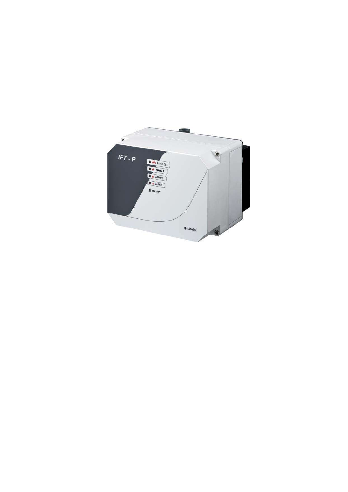
The IFT-P aspirating detector intervenes promptly by analysing the air extracted by means of a pipe
network.
Figure 1-1: IFT-P
1.2 Operating principle
The air is extracted from the protected area by means of the pipe network. These pipes should usually be
drilled in accordance with project specifications. The air is then drawn in through the inlet collectors, where
the air sample is then combined, filtered and finally channelled towards the laser analysis chamber. IFT-P
can be used in conjunction with a Tee fitting collector to connect two inlets.
IFT-P monitors the airflow for both inlets. The analysis chamber consists of an optical chamber crossed by
a laser beam, through which the air sample passes. Inside, a photoelectric sensor measures the amount
of laser-produced light reflected by the particles of smoke as they pass through. Although clean air
generates a minimal amount of refraction, smoke increases this phenomenon and can therefore be
identified. If the configured smoke levels are exceeded, various alarm indications of increasing severity are
reported (Alert, Action, Fire1 and Fire2). These indications will be linked to one or more alarm relays
configured to switch at specific smoke levels, which will be connected to the fire alarm panel.
5
Page 6

1.3 Flow monitoring
The monitoring system checks for any blockages, disconnections or gaps in the piping, making sure that
the airflow level is not above or below the set thresholds. The flow thresholds are linked to the airflow
specified during standardisation. Flow standardisation establishes the exact amount of air for that system
during normal operation and sets this flow value to 100%. The procedure is carried out during
commissioning. The detector has default flow fault thresholds and corresponding delay times, values which
can be changed using the VSC configuration software.
1.4 Alarms
The default settings for the four alarm statuses ALERT, ACTION, FIRE 1 and FIRE 2 are listed in the table
below:
Table 1-1: Standard alarm status behaviour
Level
Alert
Action
Fire 1 Stored
Fire 2
If an alarm is not stored, the corresponding relay and indications on the display will automatically revert to
normal if the cause disappears. On the other hand, if it is stored, all indications and activations will remain
active until the user intervenes manually. These alarm statuses are linked to specific air clouding values
read by the analysis chamber, regardless of the sector from which the particulate matter originated.
Behaviour
Stored
Stored
Stored
Class A/B/C threshold
0.04% obs/m
0.06% obs/m
0.08% obs/m
0.1% obs/m
Delay
3 sec
3 sec
3 sec
3 sec
6
Page 7
1.5 Front panel
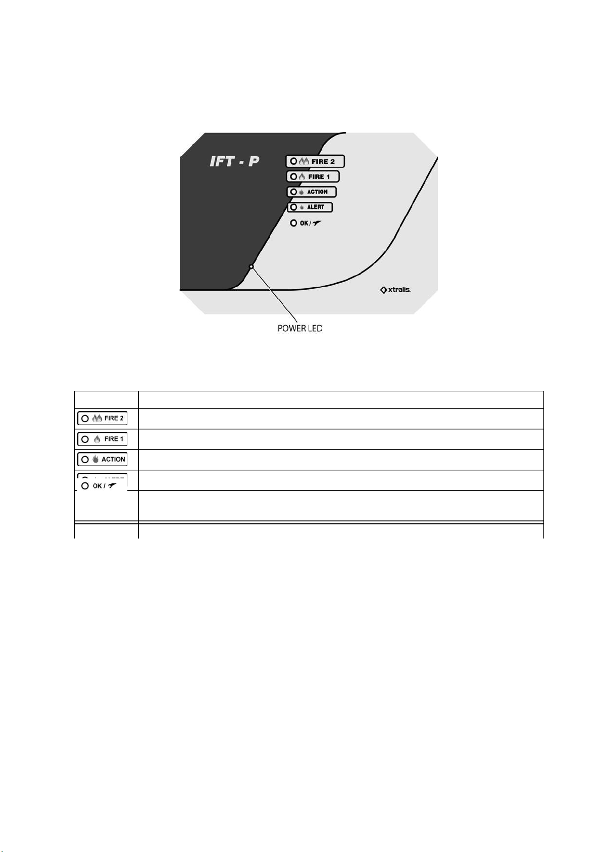
The front panel features LED indicators for the four alarm statuses and a fifth LED indicating the
OK/Fault/power supply status.
The table below describes the LEDs on the front panel.
Figure 1-2: Front panel
Table 1-2: LED description
LED Description
Red LED, active when the FIRE 2 threshold is exceeded.
Red LED, active when the FIRE 1 threshold is exceeded.
Red LED, active when the ACTION threshold is exceeded.
Red LED, active when the ALERT threshold is exceeded.
Power LED Blue LED, active when the detector is connected to the power supply.
The LED is green when no faults present, yellow when faults detected.
1.6 Communication interfaces
The IFT-P detector can be connected to a PC using the VSC software via an Ethernet port, a direct RS232
port or an RS485 port (RS232/RS485 converter).
7
Page 8
254.0MM
(10
170.0MM
(6.7
85.0
(3.35
180.0
140.0
(7.09
(5.5
)
2 INSTALLATION AND CONFIGURATION
The detectors must be installed in accordance with the installation instructions provided in this
manual, and in compliance with local regulations.
The following steps should be completed to guarantee correct system installation:
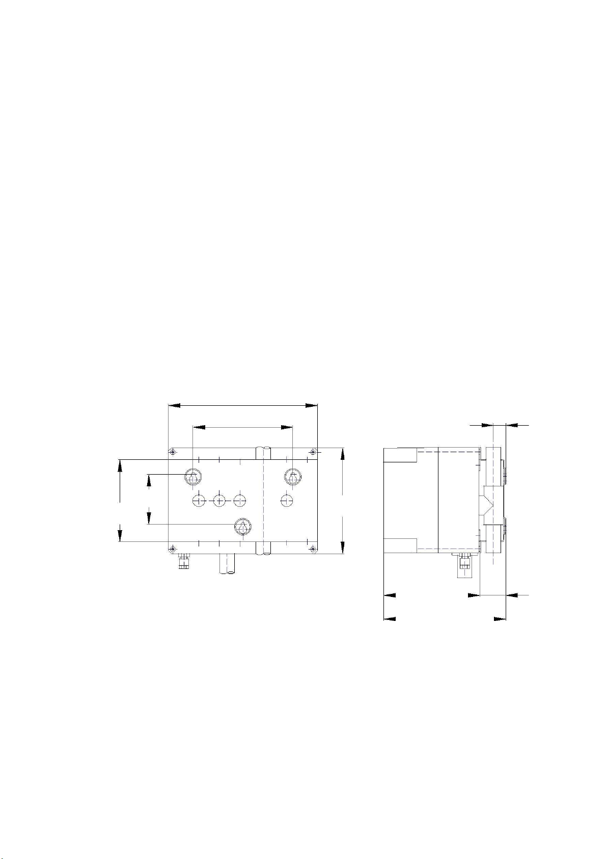
1. Fit the fixing plate carefully to a suitable wall using the three anchoring points shown in the mounting
diagrams. Please refer to Figure 2-1 for further information.
2. Connect the cables for the power supply and for the I/O modules. The ferrite cores must be
secured to the power supply cable. Please refer to section 2.2 for further information.
3. Connect the pipe network to the system.
2.1 Mounting the detector
Extreme care should be taken when selecting an installation site, to ensure that the detector:
is positioned at a practical height for commissioning, test and maintenance procedures.
is positioned so that the air outlet is free from obstructions or impediments while the system is
running.
is NOT positioned directly above heat sources or air conditioning vents.
is positioned in a safe place which cannot easily be accessed by unauthorised personnel.
IN)
IN)
MM
IN)
MM
IN
MM
IN)
164.5MM (6.48IN)
208.5MM (8.2IN)
21.0MM
(0.83IN)
44.0MM
(1.73IN)
Figure 2-1: IFT-P Mounting diagram with
dimensions
8
Page 9
A
Legend
2.2 Wiring
Note: the entire job should be carried out by authorised personnel. There are no components which
may be replaced directly by the user.
Caution: before removing the internal circuit board, make sure the power supply has been
disconnected.
2.3 Connecting the detector
The IFT-P detector is powered externally at 24 V.
The inside of the detector can be accessed by removing the front cover. This is secured with four screws
(one at each corner).
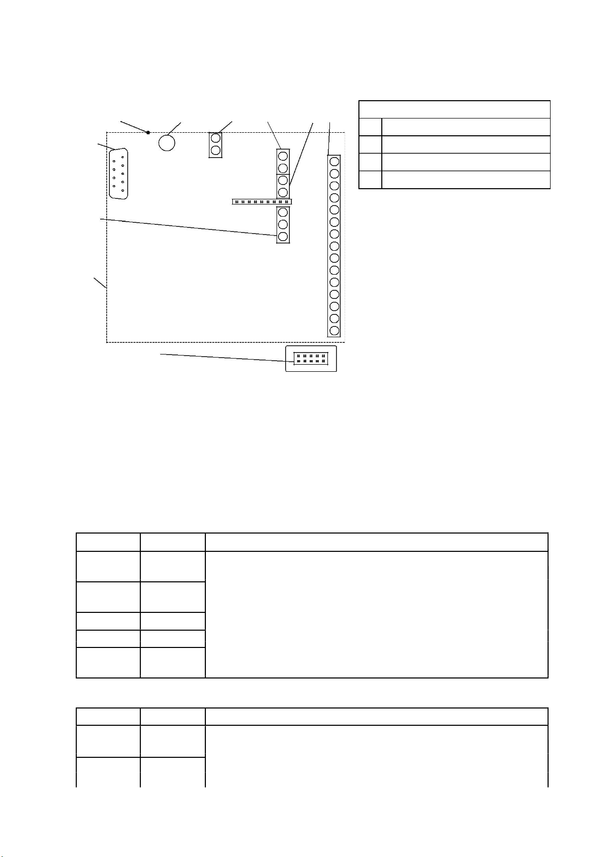
The fault relay and other I/O connections are all located on the main circuit board (front side
on opening).
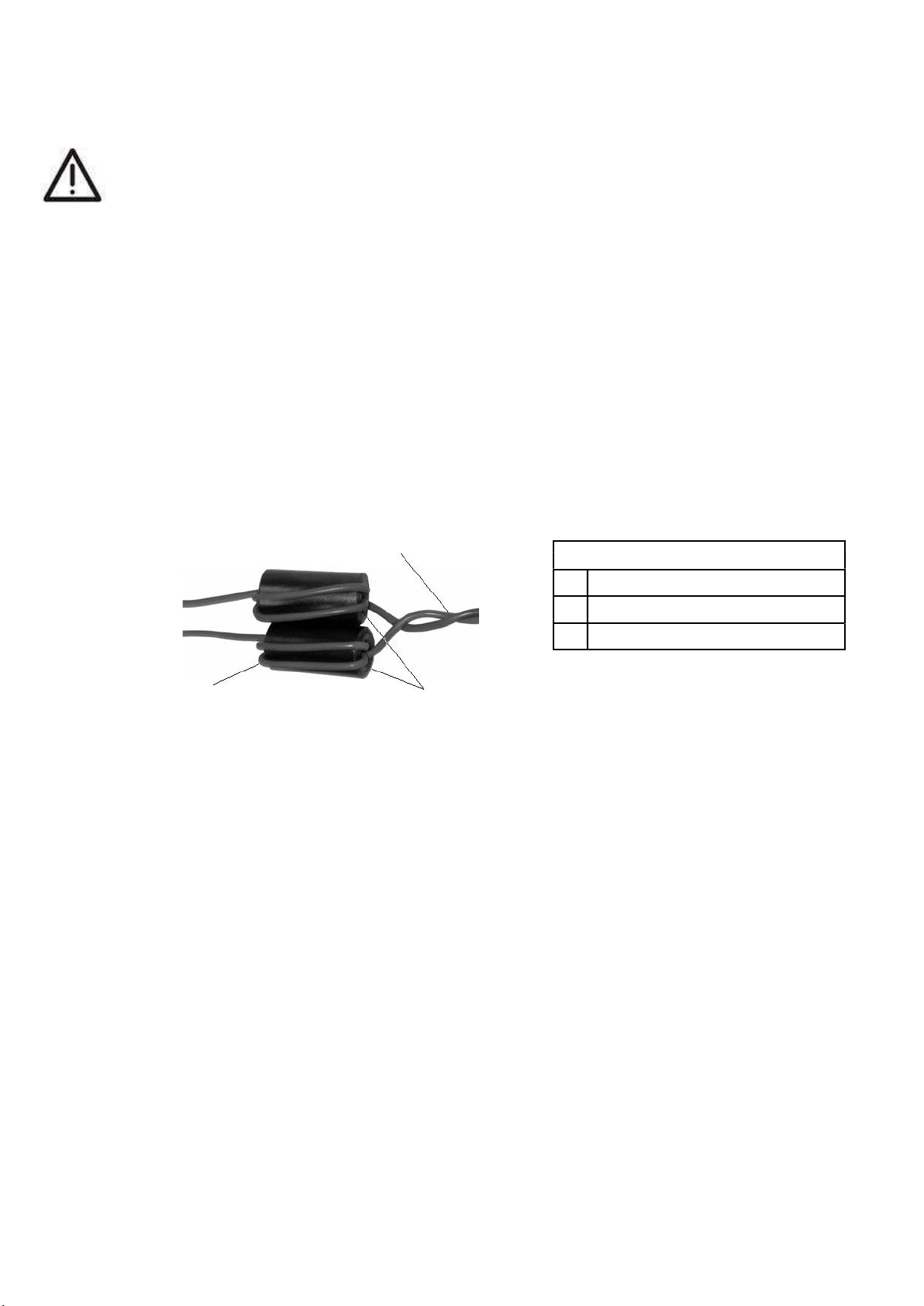
A ferrite core is supplied to ensure correct electromagnetic compatibility (EMC). This core
must be positioned inside the unit and the power supply cables wound as shown in the figure.
Ù
A Power Cords
B 2 loops
C Ferrite
C
B
Figure 2-2: Ferrite
9
Page 10
A B
CN2 CN3
CN4 CN7
1
+
24V
CN1
CN1
CN3
2
-
0V
AU
X
CN7
-
1
COM
CN2
VBAT
1
+
2
N
2
RESE
T
+
-
1
2
COMNO
3
2
4
RS232
SHIELD
1
CN
5
5
CN5
RS
48
5
NO
6
-
COM
7
+
ACT
I
NC
8
N
9
10
ALE
R
NC
11
N
12
COM
FAU
L
NC
14
NO
15
Pin Name
Description
Notes:
0V
CN2
- Power supply
Pin Name
Description
Notes
D
C
2
3
COM
13
Legend
A Ethernet
B 1A fuse
C Serial
D I/O board
Notes: please refer to appendix B for further information.
Figure 2-3: IFT-P detector circuit board diagram
2.4 Connection interfaces
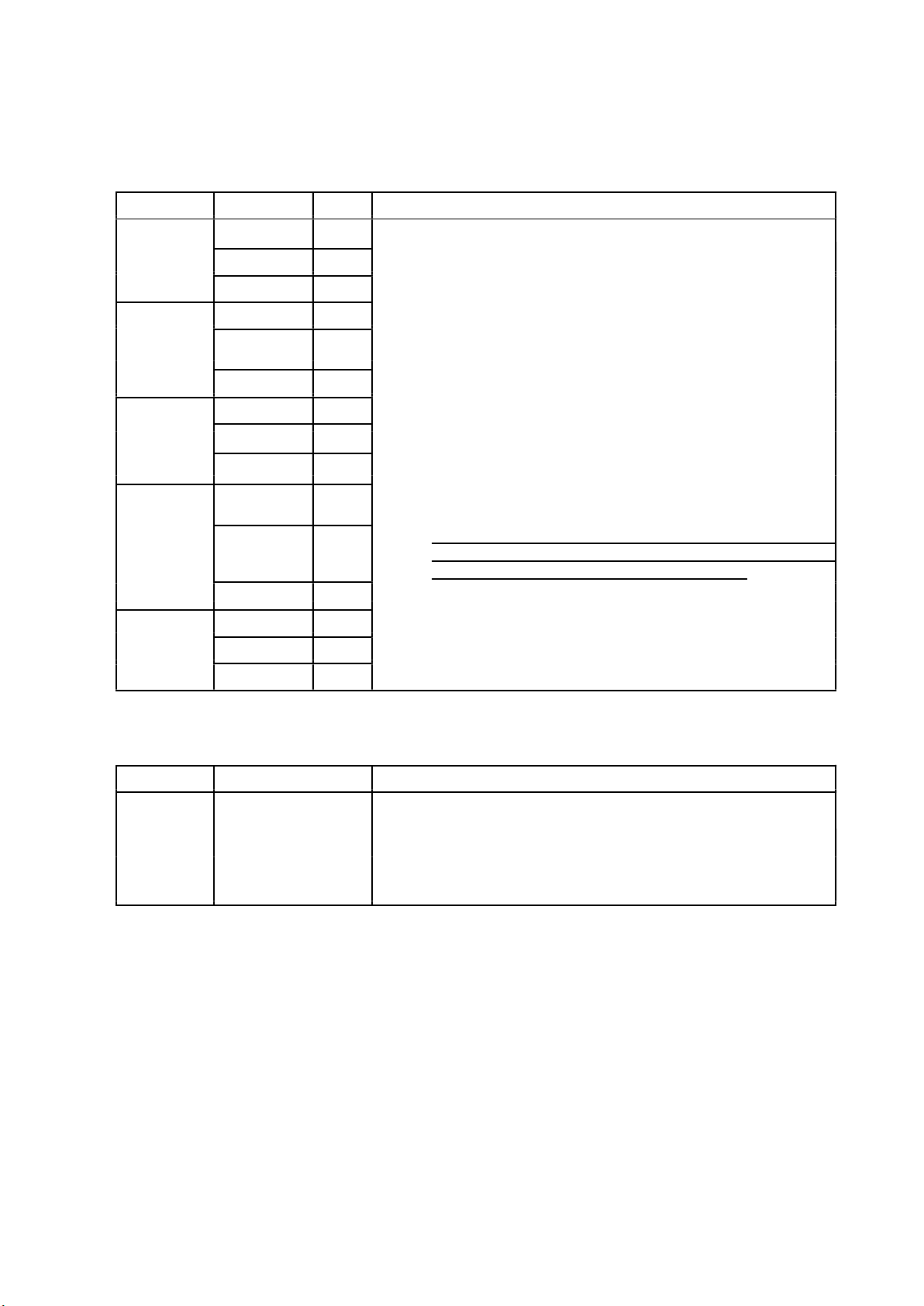
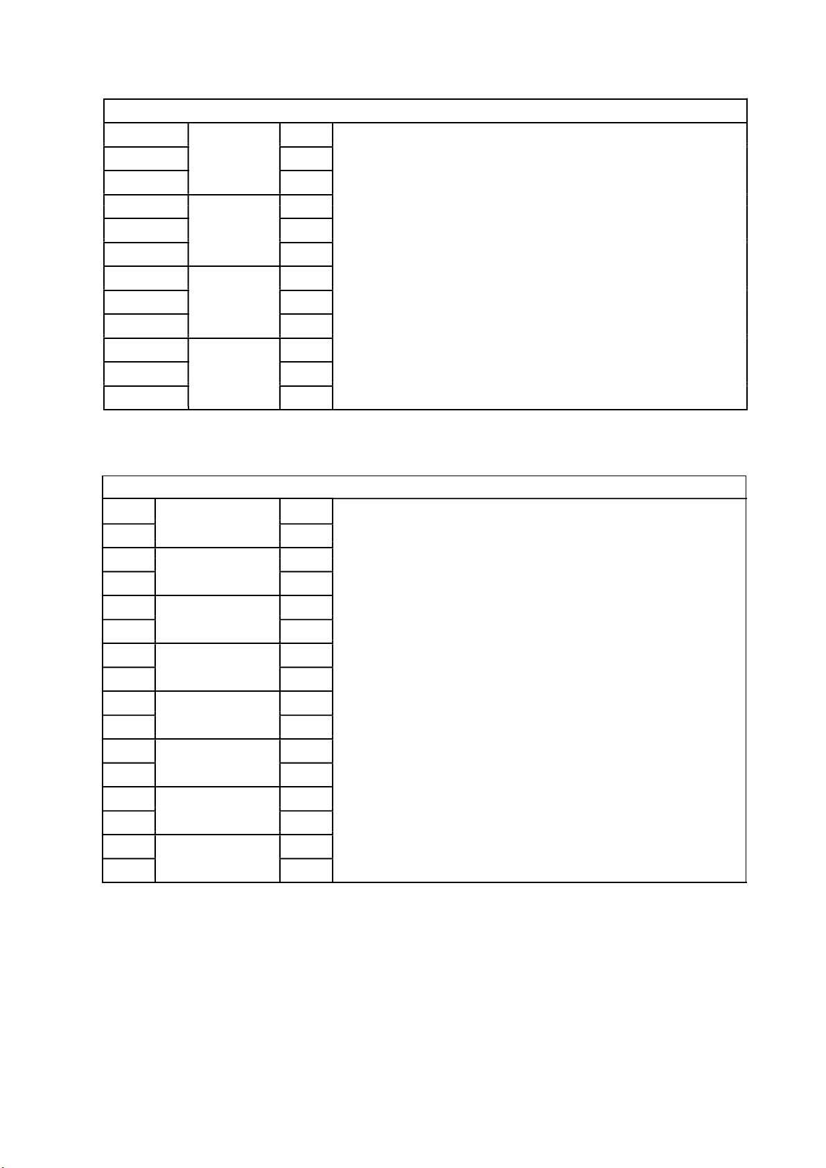
The I/O connectors for the IFT-P detector are listed in the table below.
Ethernet
Allows TCP/IP connection with a PC which has VSC or VSM4 installed on it via LAN/WAN.
CN1 – RS232 interface
2
3
Receives
Data
Sends
Allows serial connection with a PC which has VSC or VSM4 installed on it
for configuration and supervision purposes.
Requires a null-modem cable, for a distance of up to 15 m.
Data
5
1, 4, 6, 7, 8, 9
N/C
Braided strap Earth
1
(Shield)
24VDC
the null-modem cable must be “female-female”
crossover (TX-RX)
Only intended for local configuration.
Cable with minimum cross-section 0.75 mm²
W-F/H
2
0VDC
24 VDC input for external power supply.
please refer to appendix C for further information.
10
Page 11

:
11
Page 12

CN3
- Auxiliary output 24 VDC
Pin Name
Description
CN4: Remote reset input
Pin Name
Description
Remote reset
Remote isolate
CN5
– RS485 interface
Pin Name
Description
Connect up to 32 detectors in RS485 network
Notes:
when the unit is the last in an RS485 line. In all other cases,
1
2
1
0VDC
24VDC
Input -
24 VDC repeating output (to power an external warning device)
24 V opto-isolated input.
: Apply 24 V for 2 seconds.
: Apply 24 V for at least 8 seconds. When the 24 V power
is removed, the detector will revert to normal operation.
The function of this input is programmed via VSC or using the setup menu.
2
Input +
Please refer to appendix C for further information.
1
Screen
Belden 9842 cable (or equivalent)
Allows the following configurations:
Connection to a Remote Display
2
RS485 -
Connect a PC with VSC or VSM4 via converter
RS232-RS485
3
RS485 +
Make sure that jumpers 1-2, 4-5 and 7-8 are closed on CN5 ONLY
close jumpers 2-3, 5-6 and 8-9.
Please refer to section D for further information.
12
Page 13
CN7
- Output relay
Group
Pin Name
Description
NC
NO
Alarm relay for each threshold (ALERT, ACTION, FIRE 1, FIRE 2)
NC
NO
Notes:
7
NC
NO
NC (Normally CLOSED) and NO (Normally OPEN) refer to the
NC
The FAULT relay operates the opposite way round,
normal conditions the NC contact will be
OPEN and the NO contact will be CLOSED.
NO
NC
NO
Notes:
Connection to the mother board (RABBIT)
Connector
PIN description
Description
Standard Ethernet
Notes:
FIRE 2
FIRE 1
ACTION
1
2
COM
Fault relay activated when a fault event is detected.
3
4
COM
5
Alarm relays (x 4)
reached by the level of smoke detected.
6
COM
Maximum load for relays 2A @ 30 VDC.
8
ALERT
9
10
COM
status of the contact in normal conditions.
therefore in
FAULT
11
12
13
14
15
COM
the CN14 connector is only used for non-standard applications.
RJ45 – 8 pin
connections
Standard Ethernet cable.
for more detailed information, please refer to section D.1.1.
13
Page 14
Connections for 4
-
relay expansion card (optional module)
Output relay interface (i606)
C
Notes:
C
C
C
+
+
Notes:
+
+
+
+
+
+
1
2
3
4
5
6
7
8
9
10
11
12
RELAY 1
RELAY 2
RELAY 3
RELAY 4
NC
NO
NC
NO
NC
NO
NC
NO
Cable with minimum cross-section 7x 0.2 - 6A (24 AWG).
maximum relay load 2A @ 30 VDC.
please refer to section D for further information.
4-20 mA card (optional module)
Output Connections (i624)
1
2
3
4
5
6
7
8
9
10
11
12
13
14
15
16
Output 1
Output 2
Output 3
Output 4
Output 5
Output 6
Output 7
Output 8
Output specification:
-
-
20 VDC max.
4-20 mA outputs (in option 0 - 20 mA)
Cable minimum 7x 0.2 - 6A (24 AWG)
please refer to section D for further information.
-
-
-
-
-
-
14
Page 15

Detector
Input
accommodated
Max. length
of piping
2.5 Connecting the pipe network
There are various guidelines to be observed when installing the pipe network:
The piping must NEVER be glued to the detector input collector;
The pipe network MUST be fully glued (with the exception of the abovementioned point);
Use socket unions where necessary.
Caution: Do not insert ANY object other than piping into the collector. The insertion of objects may
accidentally damage the flow sensor located at the collector input.
.
Table 2-1: Specifications for collector input piping
Piping
IFT-P
25 mm (1 in)
External diameter
25 mm
2 x 100 m
2.6 Startup
After installation, the unit will need to be powered up in order to carry out the commissioning and
procedures and ensure correct operation in accordance with the piping layout connected.
After being connected to the power supply, the system requires 30 seconds to complete the startup
process.
If the detector is not switched on, check the connections and make sure the polarities have
been observed.
The detector may display faults immediately after power-up; this is normal. Reset it to restore the standby
mode of the fault relay.
2.7 Configuration
The device may be configured using:
the VSC software installed on a PC.
2.8 Flow standardisation
Flow standardisation is necessary in order for the detector to acquire the correct System flow value. This
function can be carried out using VSC and takes 6 minutes; we recommend NOT making any changes to
the detector configuration during this time.
The airflow depends on the fan speed (adjustable between 3 and 10). We recommend setting it to 5 unless
there are particularly long stretches of piping which require a different setting.
Once the pipe network has been completed, the detector will learn the current airflow value from both
collectors and will set this value to 100% of the flow.
Standardising the detector airflow using the VSC software
1. Remove the front cover.
2. Connect the detector to a PC with VSC installed on it.
3. Log in to the VSC program.
4. From the DEVICE menu, select STANDARDISE AIRFLOW.
5. Wait for approximately 10 minutes.
15
Page 16

Service activity description
Service interval
Notes
(Months) >
6
12 18 24 30 36 42 48
X X X X X X X X
X X X X X X X X
X X X X X X X X
X X X X X X X X
X X X X X X X X
*
*
Check and clean/replace the external filters on the
X X X X X X X X
X X X X X X X X
X X X X X X X X
X X X X X X X X
Complete the service forms and leave a copy for the
X X X X X X X X
3 MAINTENANCE
Notes: maintenance should be performed by authorised personnel.
3.1 Inspection
The following steps must be taken in accordance with local standards:
1. Check the LEDs at the front for fault indications;
2. Note any indications in your report;
The following pages illustrate the maintenance procedures to be carried out for the detector. These
procedures are only intended for authorised personnel.
3.2 Service
Notes: service procedures must only be carried out by qualified service technicians.
Make sure the site managers and relevant authorities have been informed and, where necessary, that the
detector outputs have been isolated in order to prevent accidental activations and alarm indications in the
building.
Checking front panel for faults
Using VSC, check and make a copy of the events
log (Faults/Alarms etc.)
Check and record the flow values
Check the installation (pipes and wiring)
Make sure the fuses are intact
Replace the filters and clean the collectors
Replace the internal filters
*
pipes
Standardise the flow (after replacing the filters)
Transcribe the flow values for each channel
Test any additional accessories
Record the results on the service form
customer
Filter replacement depends on the clouding level read by the detector during normal operation. The interval
shown above is suitable for a normal room (e.g. an office). Consider more frequent maintenance in dirtier
and more critical environments.
X X X X X X X X
X X X X X X X X
X X X X X X X X
Remote displays,
relays etc.
16
Page 17

Power supply
Power
supply
Consumption (min.)
-
Consumption (max.)
Housing
Dimensions
IP rating
Operating conditions
Operating temperature
Test
temperature
Sampled air temperature
Humidity (non
-
condensing)
Pipe dimensions
Pipe length
Coverage area
Power supply
Relay
4 SPECIFICATIONS
20 - 30 VDC
30 W
254 mm x 180 mm x 165 mm
IP30
Pipe network
Interfaces
0°C to 39°C
-10°C to 55°C
-20°C to 60°C
10% to 95%
Int. diam.: 21 mm, ext.: 25 mm
2 x 100 m (100 m per inlet)
2000 m2
Input 24V
4 alarm relays, 1 fault relay
Max. load 1A @ 30 VDC
17
Page 18

Range
UL / ULC
approval must be obtained from the
Authority with jurisdiction in the
Levels
Threshold levels can be configured
Protocols
Alarm
0.001 to 20% obs/m
Special applications sensitivity
range is 0.001%/m – 1.6%/m
(0.0003%/ft to 0.50%/ft). (For
Special Applications
Local
area).
Open Area applications sensitivity
range is (1.6%/m – 12.0%/m) or
0.5%/ft to 4%/ft.
Alert, Action, Fire 1, Fire 2.
Communication
separately.
Modbus RS232, RS485 and TCP/IP
18
Page 19
VPS-250-E
FUSE
BOARD
+
V 0V
POWER SUPPLY PCB
+
V
0V
0V +
V
0V
+
V
C NO NC
DETECTOR
I/O BOARD
1
CN1
CN3
2
-
0V
AU
X
CN7
-
1
COM
CN2
VBAT
+
2
FIR
E
NC
2
T
+
1
2
COMNO
3
2
4
1
NC
5
2
NO
6
3
CN
5
1F
IR
E
C
7
+
ACTIO
N
NC
8
NO
9
COM
10
ALERT
NC
11
NO
12
COM
13
FAULT
RELAY
NC
14
NO
15
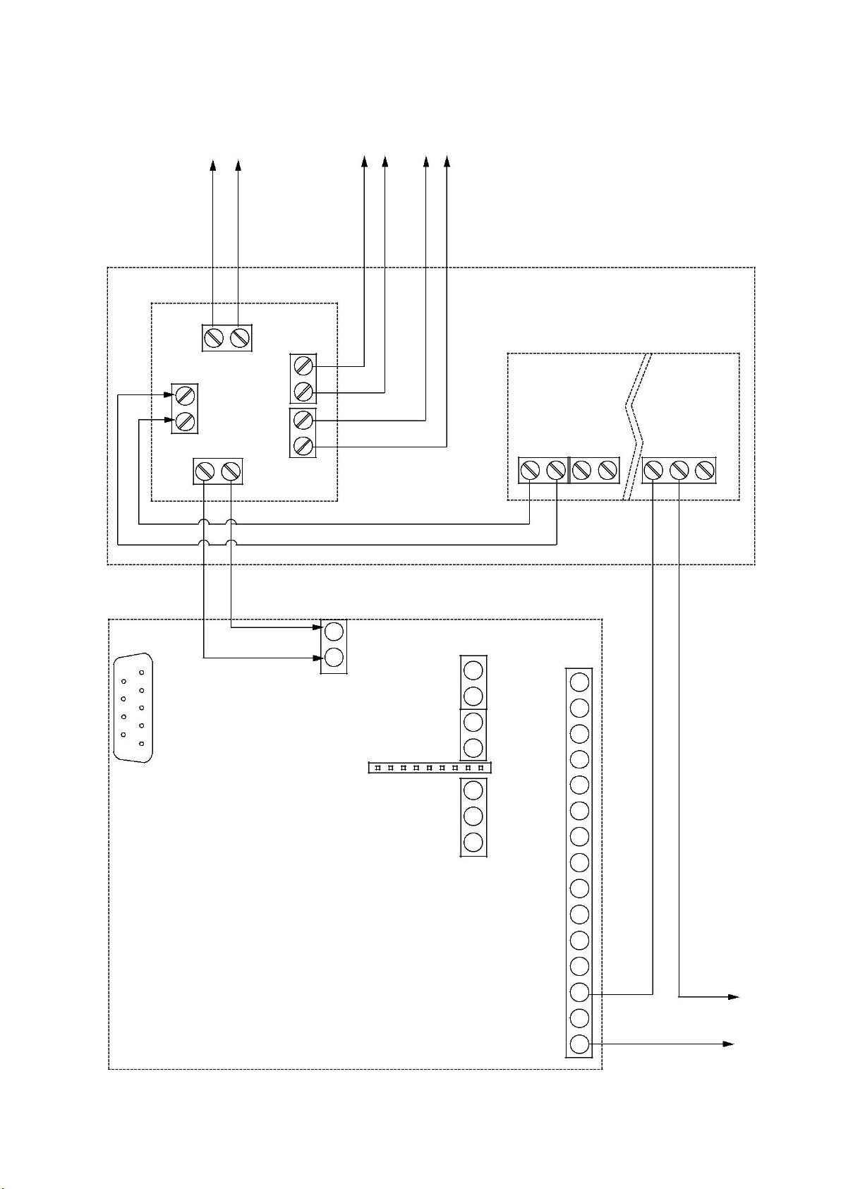
5 CONNECTION EXAMPLES
OUTPUT 2 OUTPUT 3 OUTPUT 4
OUTPUT
FAULT RELAY
OUTPUT 1
24V
+
1
RESE
RS232
-
-
SHIELD
OUTPUT
FAULT
19
Page 20

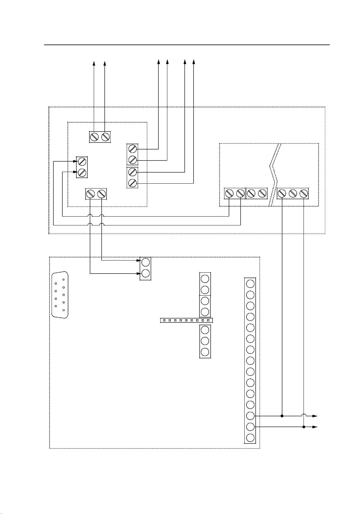
Figure B-1: Fault relay - Normally Closed
20
Page 21
VPS-250-E
FUSE
BOARD
+
V 0V
POWER SUPPLY PCB
+
V
0V
0V +
V
0V
+
V
C
NO NC
DETECTOR
I/O BOARD
1
+
CN1
CN3
2
-
0V
AU
X
CN7
-
1
COM
CN2
VBAT
1
+
2
FI
N
2
RESE
T
+
-
1
2
COMNO
3
2
4
RS232
1
NC
5
2
NO
6
3
5
7
+
ACTI
ON
NC
8
NO
9
COM
10
ALERT
NC
11
NO
12
COM
13
FAULT
NC
14
NO
15
OUTPUT 2
OUTPUT 3 OUTPUT 4
OUTPUT
FAULT RELAY
OUTPUT 1
24V
-
SHIELD
CN
FI
R
E
1
RELAY
OUTPUT
FAULT
Figure B-2: Fault relay - Normally Open
21
Page 22

 Loading...