

Page 1
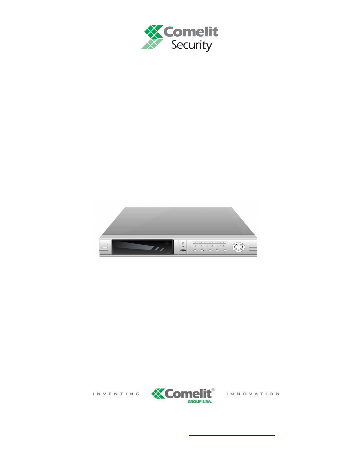
16-8 INPUTS STANDALONE DIGITAL VIDEO RECORDER
ART. 49146-49148
\
Please read this manual thoroughly before use
and keep it for future reference.
Via Don Arrigoni, 5 24020 Rovetta S. Lorenzo (Bergamo)
http://www.comelit.it – E mail: [email protected]
Page 2
2
WARNING
TO REDUCE THE RISK OF FIRE OR ELECTRIC SHOCK, DO NOT EXPOSE THIS PRODUCT TO RAIN OR MOISTURE.
DO NOT INSERT ANY METALLIC OBJECT THROUGH THE VENTILATION GRILLS OR OTHER OPENINGS ON THE
EQUIPMENT.
CAUTION
Explanation of graphical symbols
The lightning flash with arrowhead symbol, within an equilateral triangle, is
intended to alert the user to the presence of uninsulated “dangerous voltage”
within the product’s enclosure that may be of sufficient magnitude to constitute a
risk of electric shock to person.
The exclamation point within an equilateral triangle is intended to alert the user to
the presence of important operating and maintenance (servicing) instructions in
the literature accompanying the product.
The user is obliged to inform himself and to conform himself to the national and local rules concerning the monitoring
and the audio and video recording. Nobody else will consequently be held responsible for an improper use of this
system which could break the laws in force.
Page 3

16/8 channels DVR art.49146-49148 User’s Manual
3
IM PORTANT SAFEGUARDS
1. RE A D AN D KEE P TH ESE
IN S TRU C TIO N S
Plea se r ea d th is m a nua l tho ro u gh ly
be fo re u se an d ke ep it for f ut ur e
re fe re nc e.
2. CL E ANI N G
Un p lug th is equ ip m e nt fro m the wa ll
ou tlet bef or e clea n ing it. Use a m ild
ho use ho ld deterg en t, nev er use stro ng
so lv en t. Clean th e un it with a s ligh tly
da m p soft c lo th.
3. ATT A CH M E N TS
Ne v er ad d a ny a ttac hm e nt s a nd/or
eq uipmen t withou t th e ap prova l of the
man uf actur er a s su ch add it io ns ma y
re su lt in the risk of fire, elec tric sh oc k
or o th er p erson al in ju ry .
4. W ATE R A N D/O R MO I STU R E
Do no t us e this equip m ent nea r w at er
or in c ontac t with w ater.
5. ACC ESS O R IE S
Do not p la ce this e q uipm e nt o n a n
insta b le c art, s ta n d or tab le . Th e
eq uipmen t m ay fa ll, cau sing seriou s
injur y to a ch ild or ad u lt, an d s er io us
da m age to th e e q ui pm e nt. W a ll o r sh elf
mou ntin g sh ould f ollow th e
man uf actur er ’s ins tr uc tio n s a nd s ho ul
us e a m oun tin g k it app ro ve d by th e
man uf actur er . This equ ip m ent a nd car t
co m bina ti on sho uld b e mov ed w ith
ca re . Q uick sto ps , exc essive force an d
un ev e n su rf ac es ma y caus e the
eq uipmen t and ca rt c om b in atio n to
ov er tu rn.
6. VE N T IL A TIO N
If exi sting, the op en in gs or ve nt ila tio n
gr ills of the dev ic e hav e be en plan ne d
with the sco pe to su pp ly ven til at io n to
the a p pa ratus, to a ss ure a re lia ble
op eratio n o f the sa m e and to p ro te ct it
from ov erh ea ting . D o n ot b lo ck or c ov e r
thes e op e ning s.
7. PO W E R S O U RCE S
Th is e q uipm ent shou ld be ope ra te only
from th e typ e o f pow er so urce in dica te d
on th e m a rk in g la bel. I f you a re no t
su re o f t he typ e of pow er, plea se
co ns u lt yo u r eq uipm e n t de ale r or loc al
po w er co m pa n y. Warnin g if th is
eq uipmen t w o rk s with bat te ry , r is k o f
ex plos io n if ba tt er y is re p lac e d by a n
inco rrec t type . Di sp ose o f u sed b atte rie s
ac co rd in g to the l oc al law .
8. GRO U N D IN G
Do n ot defea t th e sa fe ty purpo se o f th e
po la rize d or gr oun ding-type p lug. A
po la rize d plu g has two blad es with one
wide r t ha t the other . A groun ding typ e
plug h as two bla des and a t hird
grou nding p ro ng. T he w ider b la de or th e
third p ron g ar e prov id e d for y o ur s af ety.
If th e provide d plug d o es n ot fit int o
yo ur o ut le t, c ons ul t a n e le ct ricia n f or
re pl ac em e n t o f th e ob solete o u tle t.
9.
PO W ER AND C O N N EC T IO N C A B LE S
PR O T E CT I ON
Pr otect th e c ab le s fr om b eing w a lk ed on
or p inch ed p articu la rly a t plugs a nd the
po in t w h er e thy e xi t fr om the
eq u ipm en t.
10. LIG H T NIN G S TORM
Fo r a d de
d p ro te ctio n for th is eq uipm ent
du ring a ligh tn in g sto rm or whe n it is
left u n at te nd ed a n d u nus ed for lon g
pe riod s of time, unp lu g it fr om the w al l
ou tlet an d d is co n ne c t th e an te nna or
ca ble sy stem. T his w ill p rev en t dam a ge
to the equip m e nt due to lig h tn in
g an d
po w er line surg es .
11. O V ER L O ADI N G
Do not ove rloa d wa ll o utlets a nd
ex te n sion cord s a s this ca n r es ult in the
ris k of f ire or el ec tr ic sho ck .
12. S ERV ICI N G
Do not a tt em p t to re pair t his eq u ipm en t
yo u rs elf. Th e ope ni ng and the
m ov em en t o f the co ve rs co u ld y
ou
ex pos e at h ig h vo lta g e or oth er
da nge rs . Ref er all servic in g to qua lif ie d
se rv ic e personn el.
13. D A M AGE R E Q UIR IN G SE R VI C E
Un p lu g th is equ ip m e nt fr om th e w all
ou tlet a n d r ef er se rv ic in g to q ualifie d
pe rs o nn e l un d er the follow ing
co nditio ns:
a. I f the pow er s up
ply c ord o r the plu g
ha s b ee n dam a ge d.
b.
If liq uid i s sp illed or o bjects h av e
fa lle n in to the e quipm e nt .
c.
If the equ ip m ent has bee n exp ose d
to r ain or w ater .
d.
If th e equ ip m ent doe s not ope ra te
no rmall y b y f ollow ing th e o perating
instru ction s . A dj us t o nl y tho se
co ntrols t ha t a re c ov e re d b y
op era tin g in s truc tio ns. A n im p ro p er
ad ju stm ent o f oth er c o ntro ls m ay
re su lt in d amag e.
e.
If the equip m e nt has be en drop pe d
or the c as e dam a ge d .
f.
If the equ ipm en t e xh ib its a dis tin ct
ch ang e in p er fo rm a nce.
14. R EPL A CEM E N T PART S
W he
n re plac em e n t p arts a re re q uired,
be s ur e the service te ch nician h as
us ed
re plac emen t p a rt s spe cifie d b y the
m an ufa ctur er o r th a t h a ve t he s am e
ch ara cter istic s as t he o rigin al p ar t
.
Un a ut ho rize d subs tit ut io ns may resu lts
in fi re , ele c tri c sh oc k or o th er h aza rd s.
15. S AF E T Y CHE C K
Up o n c om plet at io n o f a ny se rv ic e o r
re pair s to this e qu ip m en t, a s k th e
se rv ic e tec hn ic ia n to p er fo rm s af et y
ch eck s to de te rm ine that the eq uipm e n t
is in p ro p er ope ra ting c on d iti on .
16. INS T A LL A TI O N I N P UB L IC PL A CES
Th is kin d of insta llat
ion wou ld have to
be m ade by spec ia liz ed pe rs onn el an d
to be i n c o mpli an ce w ith the lo ca l law s
.
Page 4

4
CONTENTS
1. FEATURES AND FUNCTION…………………………………………………….…..5
2. UNIT DESCRIPTION OF FRONT PANEL…………………………………………6
3. REAR PANEL AND SYSTEM CONNECTION…..…………………………………9
4. REMOTE CONTROL…………………………………………………………………13
5. SYSTEM SETUP………………………………………………………………………13
5.1. SETUP MENU……………………………………………………………………13
5.2. SYSTEM SETUP…………………………………………………………………14
5.2.1. TIME/DATE SET………………………………………………………………15
5.2.2. HDD FORMAT SET…………………………………………………………15
5.2.3. FACTORY RESET……………………………………………………………15
5.3. DISP L AY S E T UP…………………… … … … … … ………………..… … … 1 6
5.3.1. CAMERA NAME SET…………………………………………………..……16
5.3.2. COLOR SET…………………………………………………………………17
5.3.3. AUTO SEQUENCE SET…………...………………………………………17
5.4. RECORD SETUP………………………………………………………………….18
5.4.1. AUDIO CH SET………………………………………………………………19
5.4.2. REC CH SET.……………………………………………………………..…19
5.5. NETWORK SETUP………………………………………………………………20
5.5.1. N/W ENABLE SET…………………………………………………………20
5.5.2. MAC SET………………………………………………………………………21
5.6. SENSOR SETUP…………………………………………………………………21
5.6.1. MOTION AREA SET………………………………………………………22
5.7. SCHEDULE SET……………………………………………………………………………….22
5 . 8 . B A C K U P … … … … … … … … … … … … … … … … … … … … … … … … … … 2 3
5.9. STORAGE INFO…………………………………………………………………24
5.10. PROTOCOL SET…………………………………………………………………24
6. USER’S GUIDELINE…………………………………………………………………25
7. USING THE NETWORK VIEWER…………………………………………………29
8. TROUBLES SHOOTING………………………………………………………………33
9. SPECIFICATION………………………………………………………………………35
Page 5

16/8 channels DVR art.49146-49148 User’s Manual
5
1. FEATURES AND FUNCTION
Video input: 8/16 channels; Video output: 3 channels.
Audio input: 4 channels; Audio output: 2 channels.
16 alarm input and 1 relay alarm output.
Compression mode: M-JEPG.
Support USB disk and CD_RW backup (optional).
Compatible with NTSC and PAL format.
Support zooms, auto function, watermark security.
Four optional levels of image quality: very high, high, normal, low. Record and playback frame
rate changeable for recording.
Support alarm recording, time recording.
Support loss and motion detection functions.
Multi-function searches: be able to distinguish different alarm records and time records from
ordinary records; be able to search by time, by segment or by event.
Support various playback modes: pause, several fast forward and backward play modes.
Equipped with remote device and PTZ control enables (RS485).
Triplex operation can play back, recording and network view.
480 frame (NTSC, PAL is 400) per second for view, 120 frame (NTSC, PAL is 100) per second f
or recording.
ATA-100 Hard Disk Interface, support over 200G Byte.
Page 6
6
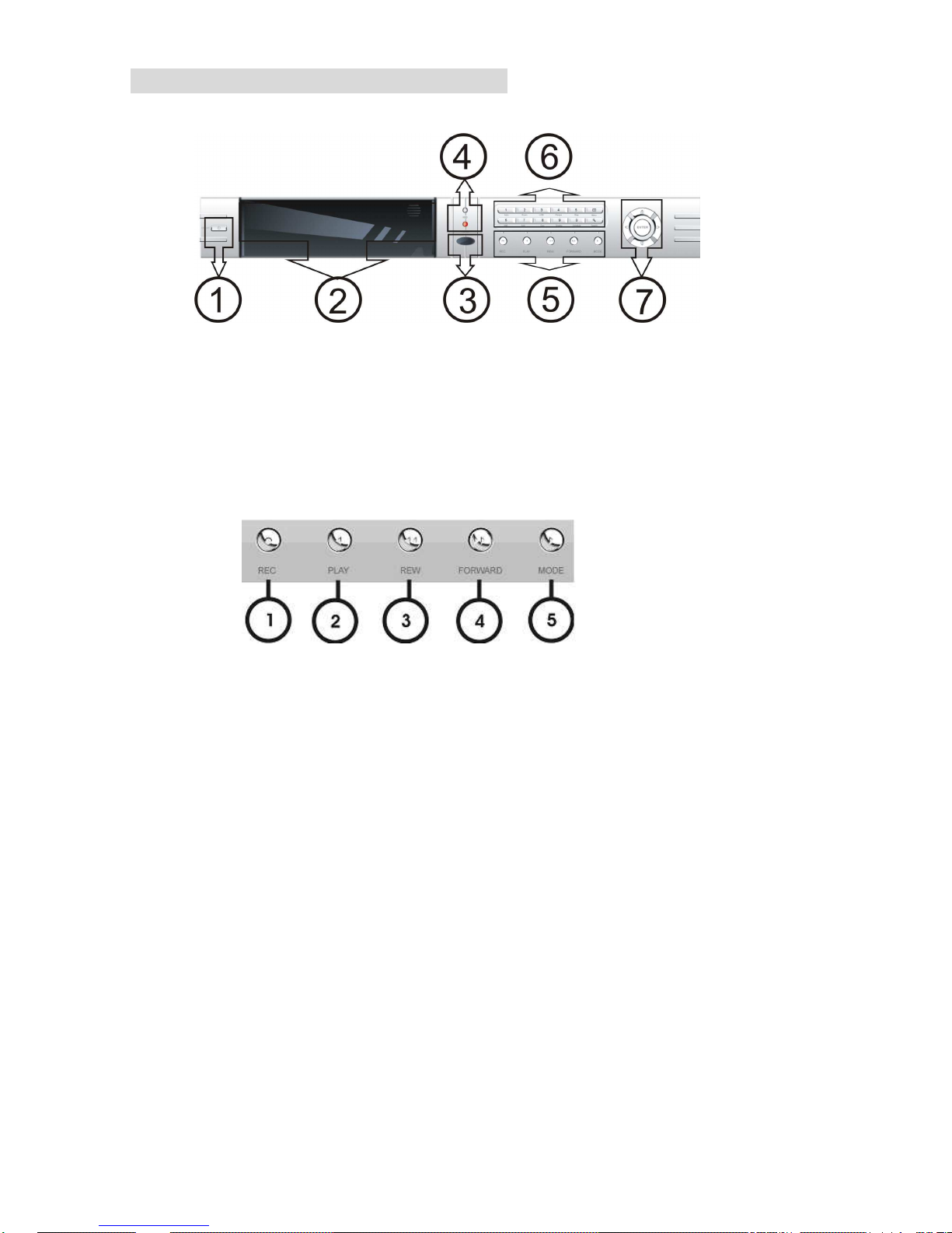
2. UNIT DESCRIPTION OF FRONT PANEL
1 - ON/OFF, DVR Power Switch.
2 - CD-RW OR HDD Window
3 - IR Window
4 - HDD LED and Power LED.
5 - Recording/Playing Control Buttons Area
1. REC: It is manual recording button. Push this button to record video to hard disk. Re-push this button, it
will stop recording. So, this button is the switch button of manual recording and stopping recording operation,
recording and stop will work simultaneously on 16 channels. This button doesn’t work in schedule mode.
2. PLAY: Push this button to start playing the video stored in hard disk. Re-push this button, it will stop
playing. So, this button is the switch button of playing video and stopping playing operations. Play and stop will
work simultaneously on 16 channels. This button doesn’t work while time recording and alarming recording.
3. REW: fast backward button. Push this button to start fast backward playing till push play button to start
normal playing.
4. FORWARD: fast forward button. Push this button to start fast forward playing till push play button to start
normal playing. The fast forward has five speeds, each time you push the button will change the speed from
slow to fast and then back to slow.
5.
MODE: mode change key, push this key to change to shift mode. Re-push to change to normal mode.
Page 7
16/8 channels DVR art.49146-49148 User’s Manual
7
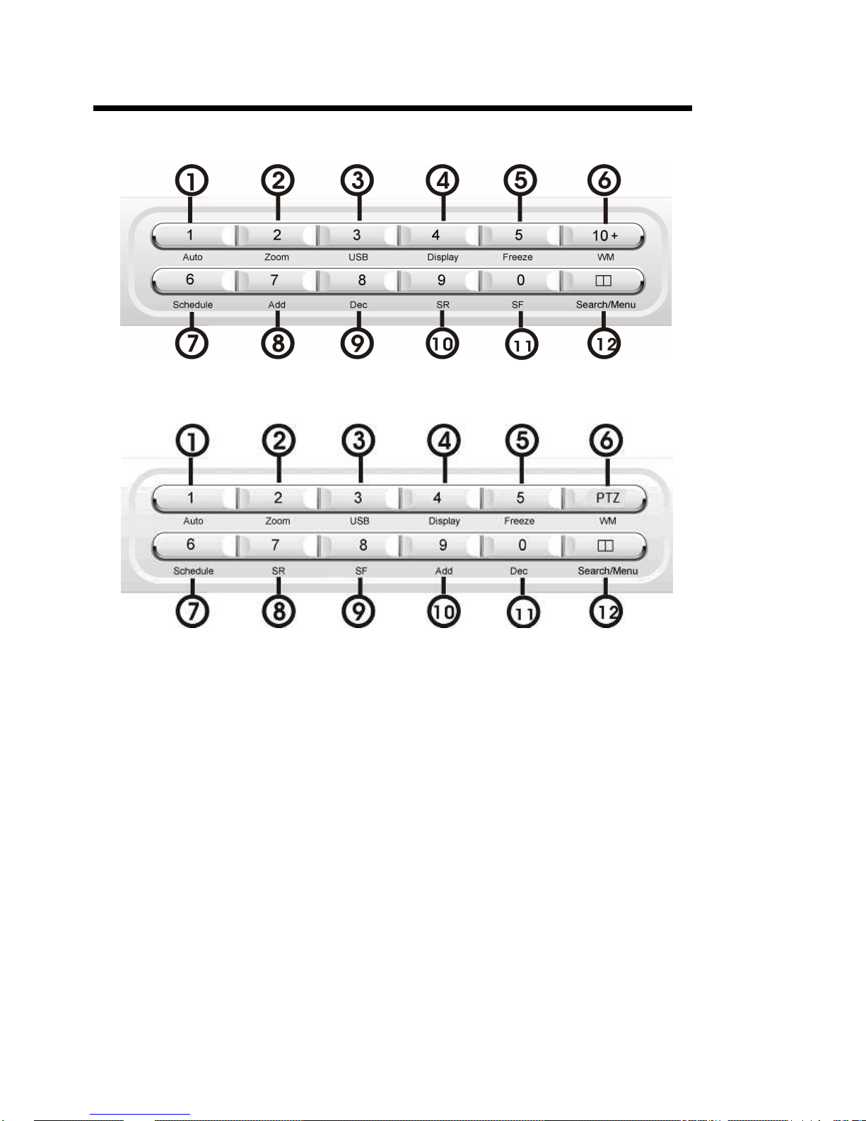
6 - Function Control Area
16CH DVR
8CH DVR
1. Auto/1: Auto key. In shift mode, push this button, the DVR will be in auto dwell state. It dwells according to
the time set in auto sequence set menu, you can set the dwell time of each channel. Push this button to quit
this mode. If not in shift mode, push this button to see big picture of channel 1. While inputting numbers, this
button is used as number key of “1”.
2. Zoom/2: Zoom key. In shift mode, push this button, the DVR will be in zoom mode. Please refer to zoom
operation in user guideline for details. Push zoom button again to cancel zoom operation. If not in shift mode,
push this button to see big picture of channel 2. While inputting numbers, this button is used as number key of
“2”.
3. USB/3: USB key. In shift mode, push this button, the DVR will start USB backup. Please refer to USB
backup operation in user guideline for details. Push USB button again to cancel USB backup. If not in shift
mode, push this button to see big picture of channel 3. While inputting numbers, this button is used as number
key of “3”.
4. Display/4: Display key. In shift mode, push this button to display current information on the screen. Push
again this to clear the information display. If not in shift mode, push this button to see big picture of channel 4.
While inputting numbers, this button is used as number key of “4”
5. Freeze/5: Freeze key. In shift mode, push this button, the DVR will be in freeze mode. Please refer to freeze
Page 8
8
operation in user guideline for details. Re-push this button to quit freeze mode, If not in shift mode, push this
button to see big picture of channel 5. While inputting numbers, this button is used as number key of “5”.
6.WM/10+: Watermark button. In shift mode, if the DVR is playing video, you can push this button to see the
watermark of the picture. If the video was recorded by this DVR and has not be changed, there will be a
watermark symbol in each picture. Push watermark key again to clear the display. If not in shift mode, push this
button and then push 1 to 6 to see big picture of channel 11 to channel 16. In 8CH DVR, this button is PTZ.
7. Schedule/6: Schedule button. In shift mode, push this button to enter schedule state. If the DVR is in
schedule state, there will be an “S” symbol on screen. Push again this button to quit schedule mode. If not in
shift mode, push this button to see big picture of channel 6. While inputting numbers, this button is used as
number key of “6”.
8. ADD/7: Add button. Push this button to see big picture of channel 7. When in system setup menu this is an
increase button. While inputting numbers, this button is used as number key of “7”. In 8CH DVR, this button is
“SR”.
9. DEC/8: Decrease button. Push this button to see big picture of channel 8. When in system setup menu this
is a decrease button. While inputting numbers, this button is used as number key of ”8”. In 8CH DVR, this
button is “SF”.
10. SR/9: Single frame rewind button. In shift mode, while in playback state, long press this button to see single
frame rewind. Press play button to play normally. If not in shift mode push this button to see big picture of
channel 9. While inputting numbers, this button is used as number key of “9”. In 8CH DVR, this button is “Add”.
11. SF/0: Single frame forward button. In shift mode, while in playback state, long press this button to see
single frame forward. Press play button to play normally. If not in shift mode push this button to see big picture
of channel 10. While inputting numbers, this button is used as number key of “0”. In 8CH DVR, this button is
“Dec”.
12. Search/Menu: push this button to enter search menu, please refer search play in user guideline for details.
Long press this key to enter menu (need password). In menu setup push this key to quit current menu.
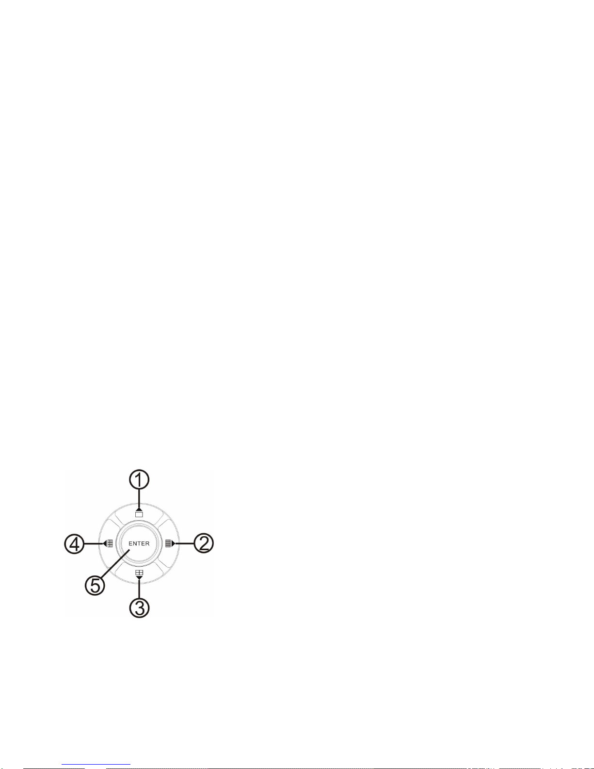
7 - Channel Choosing Control Area
1. Single Channel/up: Push this button to see full screen. Re-push this button to see the next channel. While
selecting menu items, push this button to move up the cursor.
2. Sixteen Channel /right: Push this button to see sixteen pictures
display. Re-push this button to see thirteen pictures. While selecting menu
items, push this button to move the cursor rightward. In 8CH DVR, push
this button to see nine pictures display. Re-push this button will display
next four pictures.
3. Four channel/down: Push this button to see four pictures display. Repush this button will display next four pictures. While selecting menu items,
push this button to move down the cursor. In 8CH DVR, push this button
to see full screen. Re-push this button to see the above channel.
4. Nine Channel/left: Push this button to see nine pictures display. Re-push this button to see eight pictures.
While select menu items, push this button to move the cursor leftward. In 8CH DVR, push this button to see
four pictures display. Re-push this button to see the next four pictures.
5. Enter: While selecting menu items, push this button to select the item.
Page 9
16/8 channels DVR art.49146-49148 User’s Manual
9
3. REAR PANEL AND SYSTEM CONNECTION
16CH DVR
8CH DVR
3.1 Back panel and connection terminals
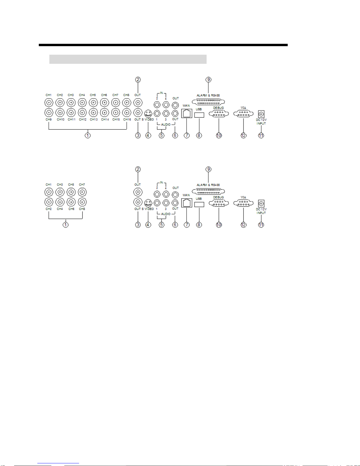
The power cable and input / output signal terminals are all at the back of the machine, The connection to
monitor, camera etc equipments are all carried out through the terminals and sockets on the back panel .
The back view of the machine is illustrated as below.
Each part of the back panel is illustrated as below:
1. Video input 1÷16 (or 1÷8); 2.main output; 3.assistant monitor; 4.S-VIDEO; 5.audio input; 6.audio output;
7.net interface; 8.USB port; 10.debug port; 11.power; 12.VGA port
9. Alarm and RS485 port define:
1-12: sensor 1 ÷ sensor 12; 13: VCC; 20-24-25: GND; 14 ÷ 17: sensor 13 ÷ sensor 16;
18: RS485A; 19: RS485; 21: COM; 22: NC; 23: NO
Page 10
10
3.2 Video and Audio Connection
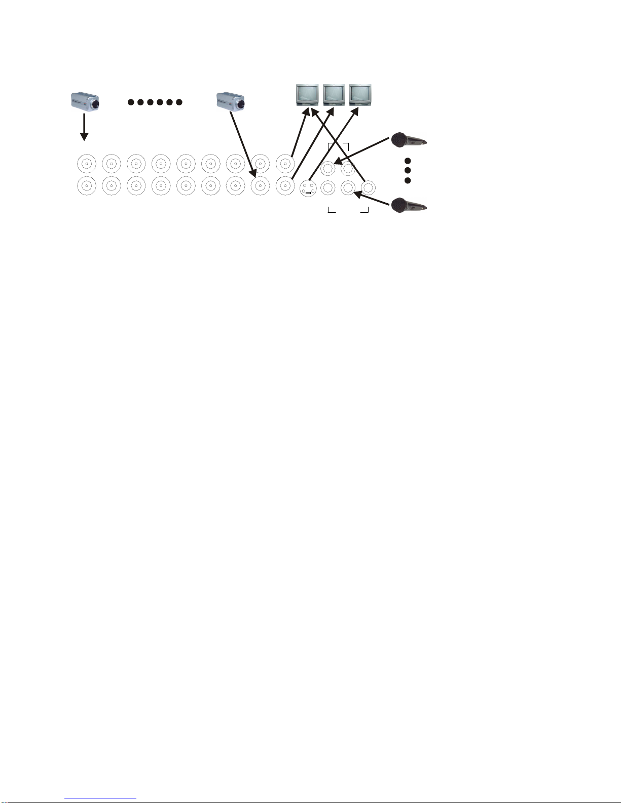
The DVR can support up to 16 cameras video input at the same time.
AUDIO
IN
OUT
3 4
21
S VIDEOOUT
OUT
CH16
CH8
CH15
CH7
CH14
CH6
CH13
CH5
CH12
CH4
CH11
CH3
CH10
CH2
CH9
CH1
Main
Out
Assisant
Out
S Video
Out
Video In 1
Video In 16
Microphone
16CH DVR
The DVR can connect 4 channel’s audio input, but you can only select one for recording. To display
the DVR picture, the DVR video output signal should be transferred to your TV set or monitor. Any
TV set that has a “video input” terminal is suitable for displaying the image. The figure above shows
the video and audio signal line connection.
Note: at one time, you can only connect one audio input, which means, if you connect an audio to
CH1, you cannot connect any CH2 to CH4.
3.3 Alarm Connection
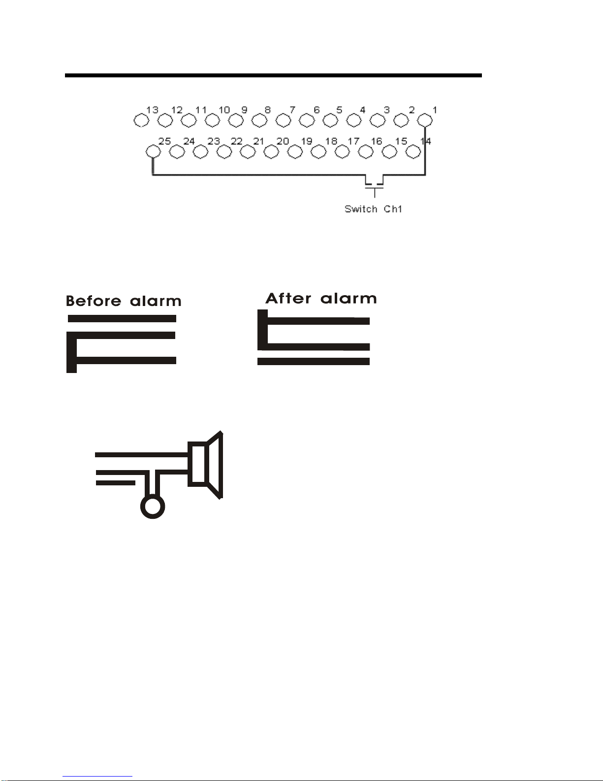
The DVR can support up to 16-alarm input and 1 alarm output.
Alarm input: there are two types of alarm input.
1. Voltage output (5V and 0V)
A: In case sensor output high voltage (5V) normally and output low voltage when triggered (0V),
then users must set DVR as low voltage alarm.
B: In case sensor output low voltage (0V) normally and output high voltage when triggered (5V),
then users must set DVR as high voltage alarm.
Please refer to the picture below, channel 2 to channel 16 are the same as channel 1.
2. Open/Close output
A: N.O. Normally open, close when triggered. DVR must set as low voltage alarm.
B: N.C. Normally close, open when triggered. DVR must set as high voltage alarm.
Please refer to the picture below, channel 2 to channel 16 are the same as channel 1.
Page 11
16/8 channels DVR art.49146-49148 User’s Manual
11
Alarm output:
There are three alarm output pin, the status of these pin are illustrated as below
N O
. .
COM
N C
. .
N C
. .
COM
N O
. .
There is an example for alarm output connection
Alarm
5V
N C
. .
COM
N O
. .
Page 12
12
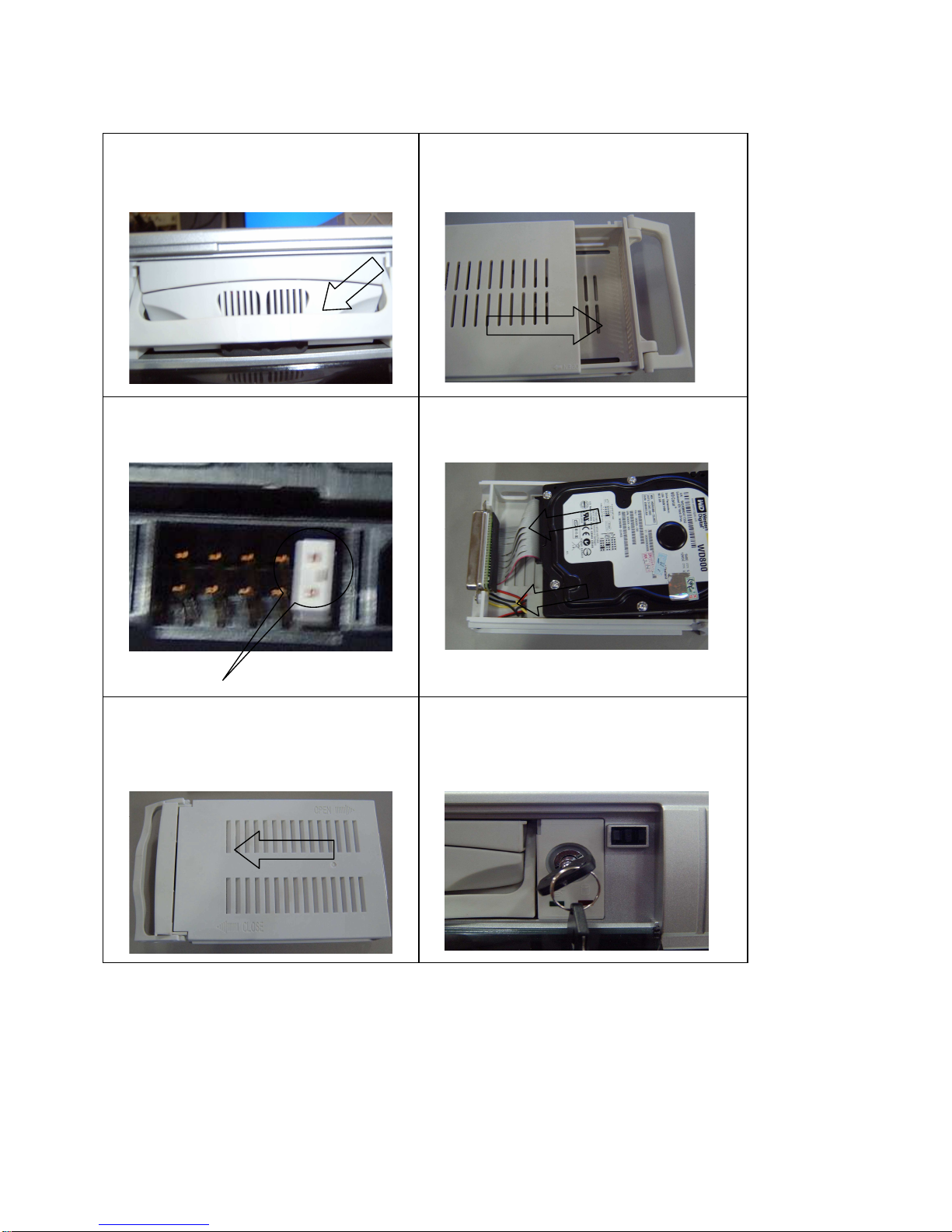
3.4 Hard Disk Connection
If you have another HDD, please jump that HDD to SLAVE, and open the machine, put the HDD to
the HDD shelf, and then connect the power and digit cable.
1. Push out the
hard drive rack from the
DVR side panel.
2. Open the top cover of the drawer.
3. Jump HDD to Master!!
Jump to Master
4. Connect the ribbon (IDE) cable &
the
power cable.
5. Close the top cover of the drawer and
put the hard drive drawer back into the
DVR
6. Lock the hard drive draw by turning the
key clockwise
Page 13

16/8 channels DVR art.49146-49148 User’s Manual
13
4. REMOTE CONTROL
0 ÷ 9, 10+: Select the channel (Full screen)
2x2: 2x2 Screen Mode
3x3: 3x3 Screen Mode
4x4: 4x4 Screen Mode
USB: USB Storage Backup
AUTO: Auto Sequence Mode
ZOOM: 2X Zoom
FREEZE: Freeze
DISPLAY: system Information
MENU/EXIT: System Setup
SEARCH: Time Search, Event Search and Start Stop Search
ENTER: Enter Next Menu
REC: Record
WM: Watermark display
PTZ: Control Speed dome
5. SYSTEM SETUP
Before using the video recorder, the first step is to set up the system according to user’s needs; otherwise
the machine will run with the default settings.
5.1 SETUP MENU
When in setup mode, push upward button or downward button, the cursor will move among the settable
items, continuous pushing will make the cursor move among the options one by one, and it can recur. The
selected one will display in yellow color.
While choosing digital fields, e.g. year, month, day, hour, minute, second etc, push leftward button or
rightward button, the cursor can move leftward or rightward among.
The several digits of one field, continuous pushing will make it move among digits one by one, and it can recur.
Please push leftward or rightward button to change the value that the cursor on, push “ENTER”
button to enter sub menu and push menu button to return to previous menu.
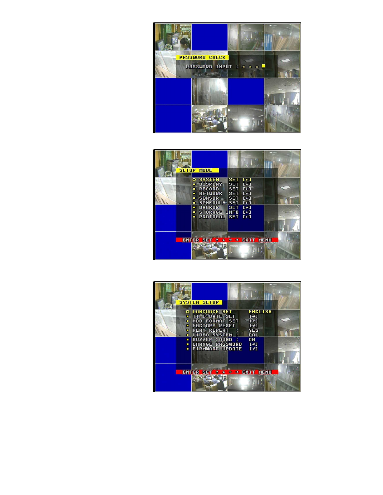
Long press the menu/search button on the keyboard or press the remote controller to enter the Setup Main
Menu. You can show password input box according setting of password set. If you fault password input 3times, then you can’t enter the setup menu. Default password is “0000”,
Page 14
14
If you enter the correct password, the main menu will display ad below.
5.2 SYSTEM SETUP
Push “ENTER” button to enter sub
menu
PLAY REPEAT: Set the Playback
Repeat
VIDEO SYSTEM: Set the NTSC/PAL
BUZZER SOUND: Set the Buzzer
On/Off
Page 15
16/8 channels DVR art.49146-49148 User’s Manual
15
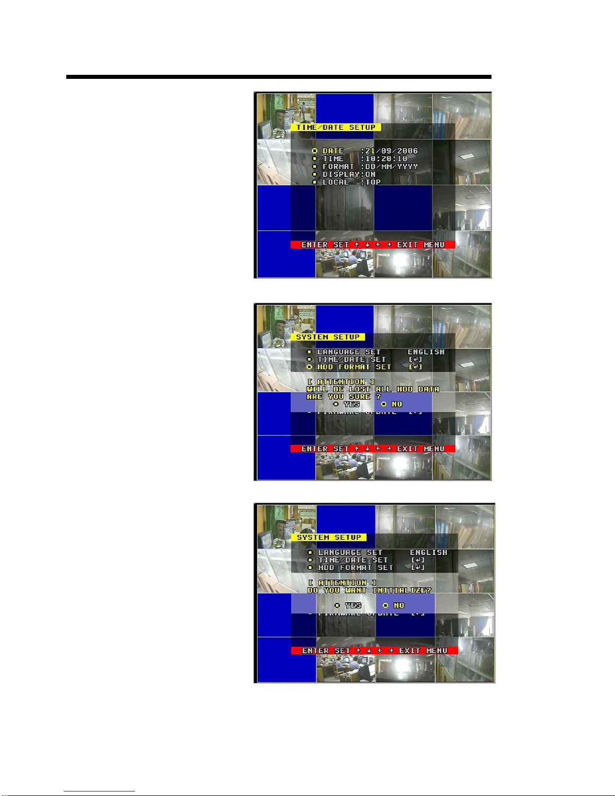
5.2.1 TIME/DATA SET
Set the date and time.
DATE: Set the date
TIME: Set the time
FORMAT: Set the time display format
DISPLAY: Set the time display on/off
5.2.2 HDD FORMAT SET
Format the hard disk
.
Select “YES”, to format the hard disk.
All video on the HDD will loss. If you
have two HDD, chose master or
slave HDD format or all formats.
5.2.3 FACTORY RESET
Initialize all the setup, the DVR will reset
to default. You need reboot the DVR.
Page 16
16
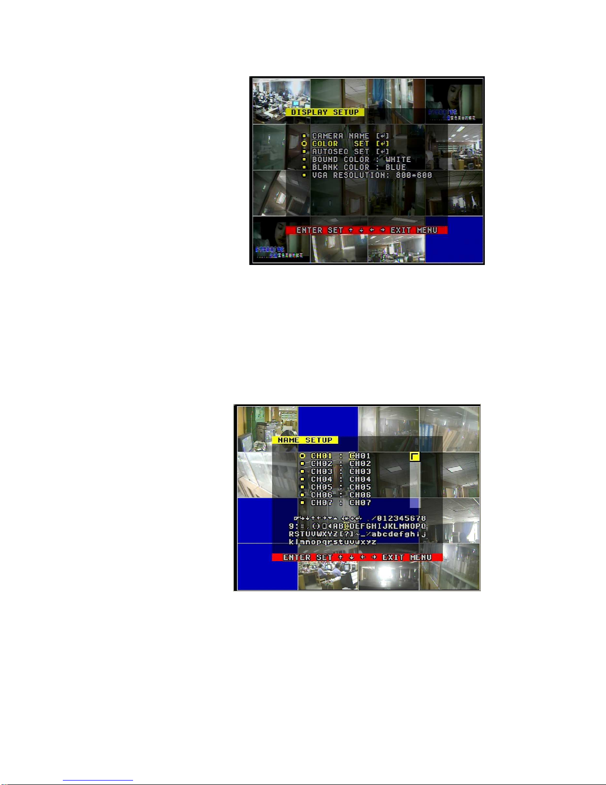
5.3 DISPLAY SETUP
BOUND COLOR: set the color of video
boundary (BLACK / WHITE / GRAY).
BLANK COLOR: set the background color
of loss video (BLACK / WHITE).
VGA set: Set the VGA resolution
(800*600 60Hz, 800*600 75Hz,
1024*768 60Hz 1024*768 75Hz,
1280*1024 60Hz)
5.3.1 CAMERA NAME SET
When the cursor moves to camera name, please push enter button, the camera name setup window will
appear, which is illustrated as below.
Each channel’s name is the combination of eight characters. Push upward or downward button to select
each character, push rightward or leftward button to modify each character, and then push enter button to save
this name.
Page 17
16/8 channels DVR art.49146-49148 User’s Manual
17
5.3.2
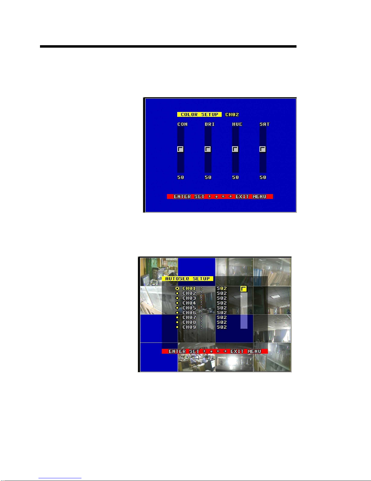
COLOR SET
When the cursor moves to color set, please push enter button, the Color setup window will appear, which is
illustrated as below.
CON: picture contrast
BRI: picture brightness
HUE: picture hue
SAT: picture saturation
5.3.3. AUTO SEQUENCE SET
Set the Display Time of Auto Sequence. Please push enter button, the auto sequence setup window will
appear, which is illustrated as below.
Set the time of the relevant channel. Time can be set in the range from 0 to 99 seconds.
Page 18
18
5.4 RECORD SETUP
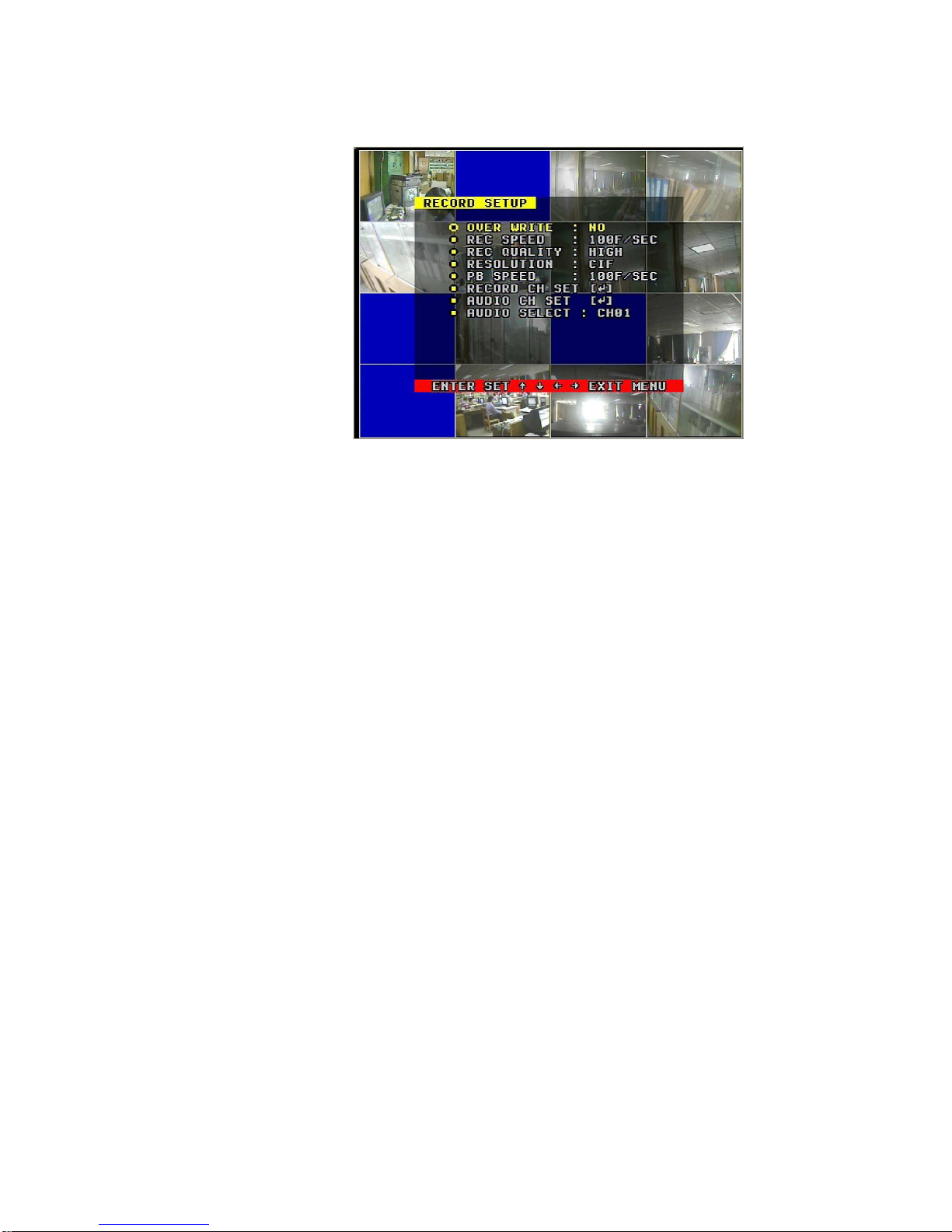
OVER WRITE: if set to “YES”, the DVR will automatically overwrite the HDD from the beginning when the HDD
is full; if set to “NO”, the DVR will automatically stop recording when the HDD is full. If there are two HDD in the
DVR, when the MASTER HDD is full, the video will store to the SLAVE HDD, and when the SLAVE HDD is also
full, the DVR will overwrite the MASTER HDD if set this to yes, otherwise it will stop recording is set to “NO”.
REC SPEED: is the recording frame rate of the DVR. Factory default setting is 30f/sec for NTSC (25f/sec for
PAL), which means DVR records the events at the speed of 30 shots of frames per second. The higher the
record frame rate, the more natural look will be displayed on the screen when you playback. The lower the
record frame rate, the more you can save the space on the hard disk. The highest frame rate is 120f/sec (PAL
is 100f/sec) when the resolution is in CIF mode.
REC QUALITY: there are four different video quality settings: VERY LOW, LOW, NORMAL, HIGH and VERY
HIGH. The higher the video quality, the clearer images when you playback; the lower the video quality, the
more you can save the space on the hard disk drive.
RESOLUTION: is the record picture size of the DVR. There are two modes: CIF and FIELD, default is CIF. In
FIELD mode, the record picture is twice bigger than is CIF mode. In CIF mode the REC speed is 120f/sec
(PAL is 100f/sec), the maximal REC speed in FIELD mode is 60f/sec (PAL is 50f/sec).
PB SPEED: is the frame rate of playback. Default is NO USE, which means the same as record.
Page 19
16/8 channels DVR art.49146-49148 User’s Manual
19
5.4.1
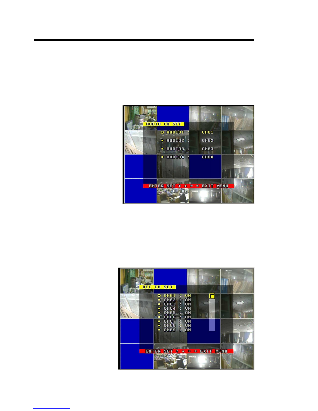
AUDIO CH SET
When the cursor moves to audio CH Set, please push enter button, the audio CH setup window will appear,
which is illustrated as below.
There are four audio input channels, for each channel you can select anyone of the 16 channels. Although
there are four audio input channels, you can only record one channel’s audio at the same time, so, for the right
audio set, you have to select one channel in these four channels in the Record Setup menu.
5.4.2
REC CH SET
When the cursor moves to REC CH Set, please push enter button. The REC CH setup window will appear, it
is different for CIF mode and FIELD mode. In FIELD mode, the window is illustrated as below. Push upward
and downward buttons to select channel, push leftward or rightward button to change the setting. If the channel
is setting OFF, this channel will not be recorded in recording mode. If the resolution is set CIF mode, the REC
CH Setup window can’t access, and you can’t set record ON/OFF for the relevant channel.
Page 20
20
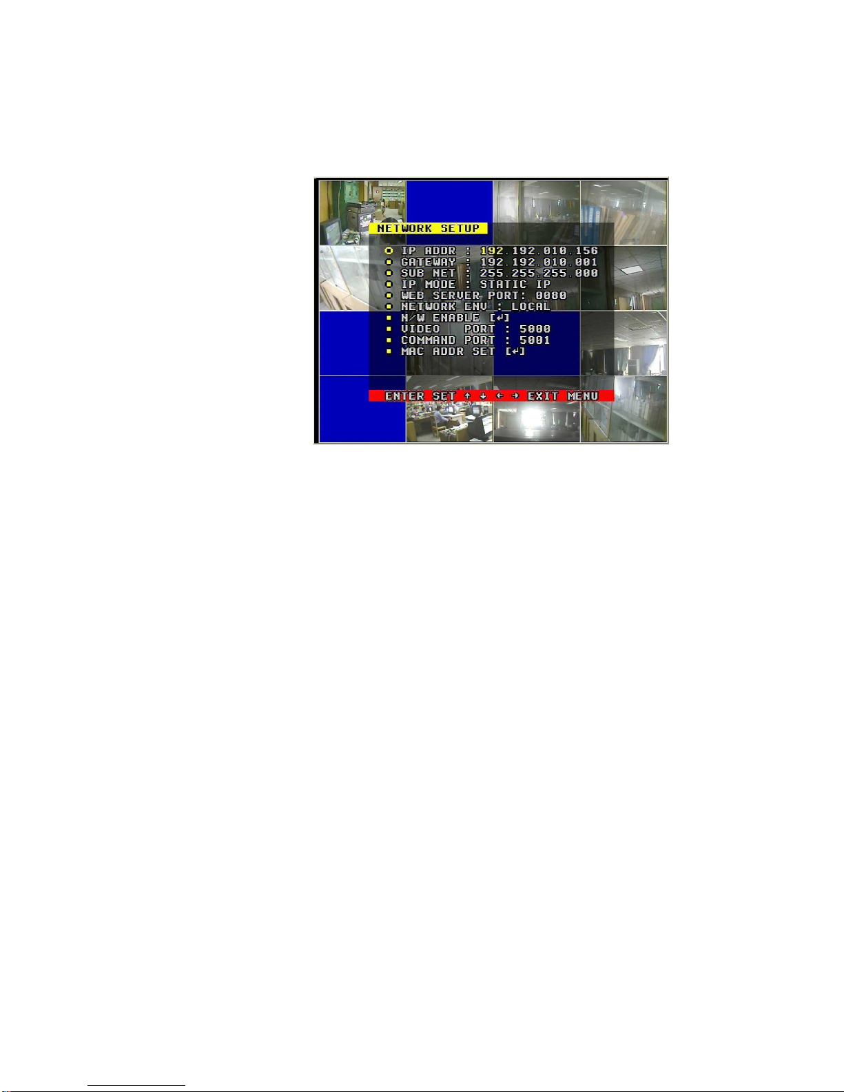
5.5 NETWORK SETUP
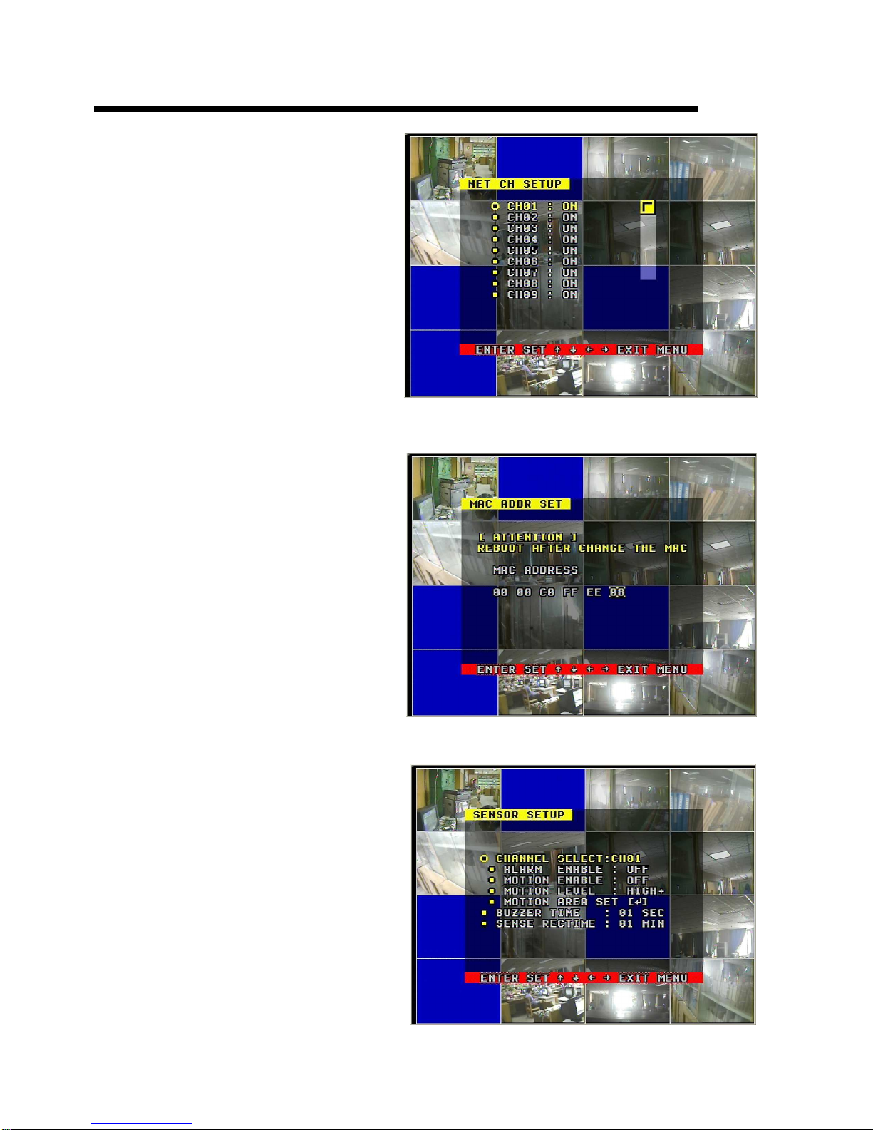
When the cursor moves to Network Setup, then push enter button, the network setup menu window will appear,
which illustrated ad below is. If a PC View software from Internet is connected to the DVR, you can’t access this
menu unless you disconnect the PC View.
IP MODE: the DVR has 2 IP modes, STATIC IP and DHCP. If you select STATIC IP, you have to set the IP
address manually, if you select DHCP mode, the DVR will automatically get the IP address.
For STATIC IP, push upward or downward button to move the cursor among the digits, you can push rightward
or leftward button to modify the digits, also, when select a digit, you can push enter button then push leftward or
rightward button to select each bit of the digit, and then push rightward or leftward button to modify the bit of
this digit, push enter to save your change.
NETWORK ENV: the DVR has three types of different network conditions: LOCAL, EXTER_LAN,
EXTER_WAN. If in local network, please select LOCAL, if for internet use, please choose EXTER_LAN, if the
internet condition is not very good, please select EXTER_WAN.
VIDEO PORT: the video transmits port for the computer.
COMMAND PORT: the command transmits port for the computer.
If you change any of the VIDEO PORT and COMMAND PORT or MAC address, you have to restart the DVR to
use the “net viewer” software.
Note: if you have change the MAC address, you can’t see the “MAC ADDR SET”
5.5.1. N/W ENABLE SET
If you set the channel OFF, this channel will not transmit to the network, so if you want to see a
channel from network, you have to set this channel on.
Page 21
16/8 channels DVR art.49146-49148 User’s Manual
21
5.5.2. MAC SET
When the cursor moves to MAC set then push enter button. The MAC set window will appear which is
illustrated as below.
If you have more than one DVR in a local area
network, you have to set each DVR to have an
exclusive MAC address, but remember that
you have only one chance to modify the
MAC address, once you have changed the
MAC address, this menu will not appear!
5.6 SENSOR SETUP
When the cursor moves to sensor set then push enter button. The sensor set window will appear which is
illustrated as below.
Page 22
22
ALARM ENABLE: alarm trigger switch. You can be set to off, N.C. or N.O. If users set it to off, the DVR will
ignore the alarm input.
MOTION ENABLE: motion alarm switch. You can be set to on or off. If users set it to off, the motion alarm will
be ignored.
MOTION LEVEL: motion sensitivity level. If the figure in the picture is small, please set to high of very high. The
default is normal.
BUZZER TIME: buzzer sound time when there is a sensor or motion alarm.
SENSOR RECTIME: when a motion or sensor alarm occurred, the DVR record last time, the default is 1 minute.
Note: users should press schedule button after setting up the parameters so to activate the settings.
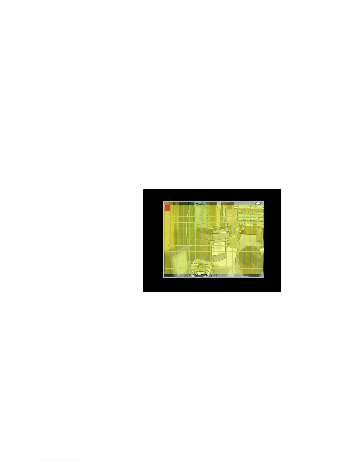
5.6.1 MOTION AREA SET
Turn the Motion Block ON/OFF.
When the cursor moves to Alarm set, then push enter button, the alarm setup window will appear, which is
illustrated as below. Please push upward, downward, leftward, rightward button to move the cursor and push
enter button to change, long push enter change all value the same as you selected.
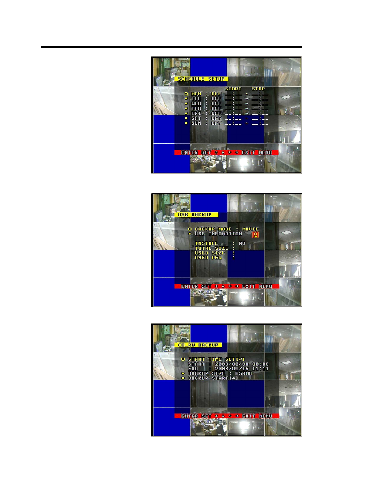
5.7 SCHEDULE SET
When the cursor moves to Schedule Set, please push enter button, the schedule setup window will appear,
which is illustrated as below.
You change a recording schedule during a week using this setup, from Monday to Sunday; you can set a
period time in each day.
START: start record time
STOP: stop record time
SUN ÷ SAT: Select the weekday for recording (00:00-23:59)
Page 23
16/8 channels DVR art.49146-49148 User’s Manual
23
5.8 BACKUP
5.8.1 USB BACKUP.
Plug in the USB device, and press
enter button, you can see the right
picture.
There are two types of backup mode:
STILL and MOVIE, in STILL mode you
can backup picture, in MOVIE mode
you can backup video.
5.8.2 CD_RW BACKUP
If the DVR is connected to a CD_RW,
you can use CD_RW BACKUP. Select
this menu, you can see the right
picture.
Select the time of backup and backup
size you need, and then select the
backup start.
Page 24

24
5.9 STORAGE INFO
Storage information shows the
information on hard disk.
MODEL: Model Number of the Hard Disk
CAPACITY: Total capacity
USED SIZE: Space used
OVER WRITE: The number of times
overwritten
5.10 PROTOCOL SET
Set the right protocol, you can control the SPEED DOME by the DVR.
When the cursor moves to Protocol Set, then push enter button, the protocol set window will appear, which is
illustrated as below. Push up or down button to move the cursor, and push right or left to change the value.
CHANNEL SEL: select the channel that is connected to the speed dome, which you want to control.
BAUDRATE: select from 1200 bps to 19200 bps. The default is 2400 bps.
DOME ADDR: address of the speed dome, changeable from 0x00 to 0xff.
PROTOCOL: the protocol that DVR control speed dome, include PELCO-P, PELCO-D, NEON, LILIN. The
default is PELCO-P.
Page 25

16/8 channels DVR art.49146-49148 User’s Manual
25
6. USER’S GUIDELINE
6.1 start the machine
Before starting the machine, please make sure all the items in the “Important Safeguards” at the beginning
of this manual are fulfilled.
Before starting the machine, please check the system connection, input and output equipment connection.
Please insure the video-recorder’s input video (NTSC/PAL) and the monitor (NTSC/PAL) meet the demands.
Start exterior equipment after checking over.
Insert the removable hard disk case to the end, and lock it up (turn right the hard disk lock); connect the
power, the machine start to work.
6.2 Turn off the Machine
Normally turn off the machine when the system shutdown, which means do not to turn off the machine while
playing or system setting up, especially not to turn off the machine while recording.
Push recording button to stop recording or push playing button to stop playing or exit from system setup
menu, then turn off the power.
If do not use the video recorder for a long time, should pull out the power line from the electrical outlet.
6.3 Normal Recording
Connect the power to all related equipments and ensure that there is video input.
Push display button to check spare space of the hard disk, if there is no much space, please think whether
to change hard disk first or select overwriting modes.
Check recording parameter setup before recording; select video quality, frame rate. You cannot change
record setting during the process of recording,
Manual recordings belong to normal recording. Under the manual mode (non-schedule status), pushing
record button will record all video channels.
Push the record button to begin recording, sixteen channels will start simultaneously recording. While in
normal recording mode, push record button, and enter the right password, it will stop recording.
During the process of recording, if the hard disk is full and the system is set to automatic overwrite,
then the recording will not be interrupted, and it begins to overwrite the earliest recorded area; if the
system is set to overwrite disable, it will stop recording.
6.4 Alarm Recording
Alarm recording is not started by manually pushing record button, the entire recording started by manually
pushing the record button are normal record.
Alarm recording can be activated by alarm input signal or motion, so it must to check whether the
connection of
Page 26

26
alarm input equipment is correct, stable and reliable, and the alarm set is right, please refer to sensor setup.
The prerequisite condition of whether the alarm recording can be activated by exterior input signal or the
motion is that the system must be set on schedule. In the menu of alarm setup, for exterior input alarm,
alarm enable of that channel must set to “ON”. For motion alarm, motion enable of that channel must set
“ON”, and set the right area for motion detect.
Under the state of off-schedule, system will never start alarm recording. Setting schedule on or off is
achieved through pushing the schedule button on the front panel, but not through system setup menu and
window. Under schedule-on situation, the character “S” will display on the screen,
Alarm video recording cannot stop by pushing record button, but can stop by removing schedule. Because
once the system is set on schedule, the schedule cannot be removed randomly, so there is a password
protection to remove schedule, only after inputting correct password, you can take schedule off.
Check alarm recording setup before recording; confirm the video quality and the frame rate, the record
setting cannot change during recording process.
As long as the alarm input signal is effective, the alarm recoding continues, when the alarm input signal
loses efficacy, the time set up by “REC TIME” becomes effective, and when the time goes out, the alarm
recording automatically stops. In course of this, if you want to manually stop alarm recording, the only way
is to remove schedule (answer the password).
6.5 Time Recording
Time recording starts and stops recording automatically according to the pre-arranged time period. It is
applied to fixed timetable. For example, the periodical work time recoding (of off time recording) with fixed
start/stop time.
To start time recording function, besides making record schedule setup beforehand, must push down the
schedule button on the front panel to set schedule on. While pushing down this button, the schedule symbol
“S” will display on the screen. Without pushing the schedule button, the time recording parameter setup will
not work.
The prerequisite condition of whether the time recording takes effective is system must be set on schedule.
In time record state, you can push again schedule button the enter password to stop time recording.
Because time recording is correlated closely with time, so before using this function should previously adjust
the time.
6.6 Playback
Push play button, system begins to play the images recorded
In the process of playing of fast backward playing, pushing play button will begin normal playing from the
current place.
Page 27

16/8 channels DVR art.49146-49148 User’s Manual
27
In the process of fast forward playing or fast backward playing, re-pushing play button can resume play.
Continuously.
In the process of fast forward playing or fast backward playing, pushing play button will begin normal playing
from the current place.
Continuous pushing forward button will change the fast-forward among five levels of speed (X2, X4, X8, X16,
and X32) circularly. Continuous pushing reward button will change the fast backward among four levels of
speed (X2, X4, X8, and X16) circularly.
During playback mode, long press single frame rewind button will play backward frame by frame; long press
single frame forward button will play forward frame by frame. Push play button to play normally.
Push again play button will stop playing.
6.7 Search play
Push search button, search play window will display on the screen.
TIME SEARCH: search play by input time.
EVENT SARCH: search play by event list.
START STOP SEARCH: search play by segment.
Push upward and downward button to move cursor, push enter button to enter submenu you select, push
search button to quit from search menu.
6.8 Time search
When the cursor moves to Time Search, then push enter button, the time search window will appear.
Their red block means there has video at that time
Push leftward and rightward button to move the cursor among year, month, day, hour and minute, if you
select the year and push enter button you will select month and so it is with day and hour, Push ADD and
DEC button to modify the time. If you select the minute and that minute has a red block then you can push
enter button to play the video from that time you selected.
6.9 Event Search
When the cursor moves to Event Search, then push enter button, the event search window will appear.
There are four types of event list: MOTION, ALARM, SCHEDULE and NETWORK. MOTION means motion
alarm recording; ALARM means sensor alarm recording; SCHEDULE means time recording; NETWORK
means network recording
Push upward and downward button to move the cursor among the event list, push leftward and rightward
button to see previous or next page, push enter button to play the segment you select. Push search button
back to Search Play menu.
If you want to change the HDD between MASTER HDD and SLAVE HDD, just long push search key, then
push enter key to change, push menu to give up.
Page 28

28
6.10 Start Stop Search
When the cursor moves to Start Stop Search, then push enter button, the Start stop search window will
appear.
All record segments are displayed here, push upward and downward button to move the cursor among the
segment list, push leftward and rightward button to see previous or next page, push enter button to play the
segment you select. Push search button back to Search Play menu.
If you want to change the HDD between MASTER HDD and SLAVE HDD, just long push search key, push
enter key to change, push menu to give up.
6.11 USB Backup
Plug in the USB device, go to the menu of Backup set, check that if the USB device was detected or not, and
the free space of the USB device is enough or not, select the backup mode, then quit the menu setup.
In shift mode, if you select “STILL” for the backup mode in the Backup Set menu, push the USB button, it
begin to backup the main out picture to the USB device, there will be a “S” blinking on the screen, when stop
blinking the backup of the picture is done, you can plug the USB device out and see the picture on a
computer.
If you select “MOVIE” for the backup mode in the Backup Set menu, push the USB button in shift mode, it
begin to backup the main out video to the USB device from the moment, push USB button again to select the
end of the backup video, there will be a “A” blinking on the screen. This may take a little time, and make sure
the USB device has enough free space, if blinking stops, the backup is ok, you can see the video on a
computer with net viewer software.
6.12 USB Update
Create a folder named “firmware” in the USB root directory, copy the update files to the folder, plug in the
USB device, go to the menu of update set, check that if the USB device was detected or not, go to the
Firmware Update menu and select USB method, move to Update Start and press enter button, update will
start.
Then reboot the DVR.
NOTE: do not shut down the DVR when the DVR is updating, it may cause fatal problem.
6.13 Zoom
In shift mode, press zoom button or press the zoom button on the remote controller, the DVR will be in zoom
mode. Press upward, downward, leftward or rightward to move the zoom area, then push enter button to
zoom, press zoom button again to cancel zoom operation.
6.14 FREEZE
Press the Freeze button on the remote controller or keyboard, on the full screen mode to pause a screen; on
the other modes, press the Freeze button to see the Freeze menu. Here, select the channel number to
freeze.
Page 29
16/8 channels DVR art.49146-49148 User’s Manual
29
6.15 PTZ OPERATION
This DVR can control speed domes, which are connected to the DVR.
To control the speed dome, make sure all the lines are correctly connected, first you must set the right protocol,
baud rates, and speed dome’s address for each speed dome, please refer to protocol set.
PTZ can only be operated by remote controller, press the PTZ button on the remote controller,“PTZ” will be
display on the screen, then select 1 to 16 to choose PTZ channel, the channel number will be displayed after
“PTZ”. You can press upward, downward, leftward, rightward button to move the speed dome, and press the
button again or press enter to stop. If you press the IRIS button, the character “IRIS” will appear on the
screen, then you can press the “+” and “-” button to change the IRIS. The same to control the focus, zoom,
and speed, also press enter button to stop.
Press the PTZ button one more time to exit from PTZ control. In 8 CH DVR, you also can use PTZ of the DVR
control front.
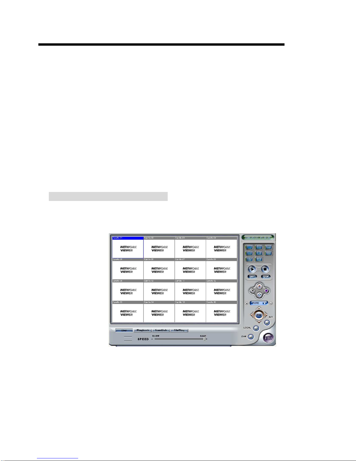
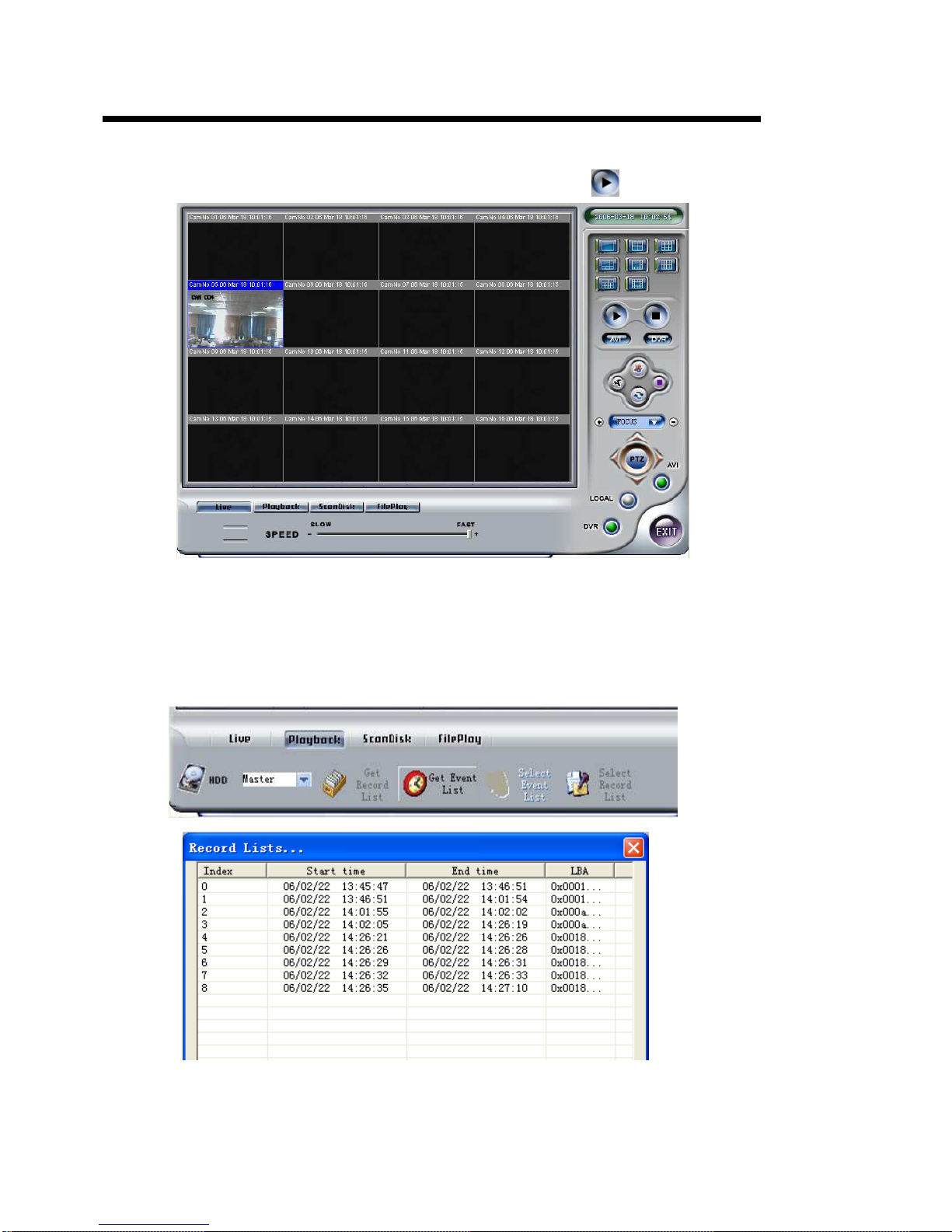
7. USING THE NETWORK VIEWER
Using the PC view software, you can view the DVR through Internet or local network, also, you can view and
backup the video information on the HDD through a computer.
Open the software; you will see the window below:
Page 30
30
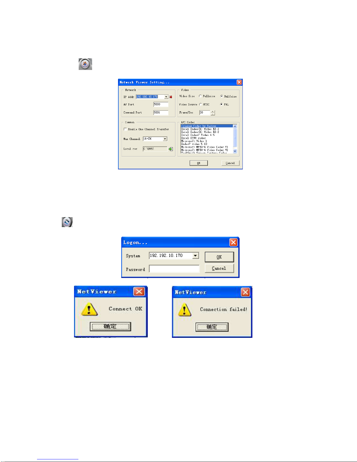
7.1 Setting
Please click button, you will see the window below: enter the IP address and click “OK” button.
IP Address: Set the IP of the board
Port: Set the communication port and AV port
7.2 Viewer connect
Press button, you can show login box.
<Connect success> <Connect fail >
Page 31
16/8 channels DVR art.49146-49148 User’s Manual
31
7.3 Liveplay
You can select this button to see live picture, just click the play
button.
7.4 Playback
Click “Playback”, search window will display. First, you have to select the HDD of the DVR, then click the
“Get record list” or “Get event list”. If the DVR has record list, you can see the window below:
Double click the record list, you can see the playback video.
The event list operation is the same as record list operation
Page 32
32
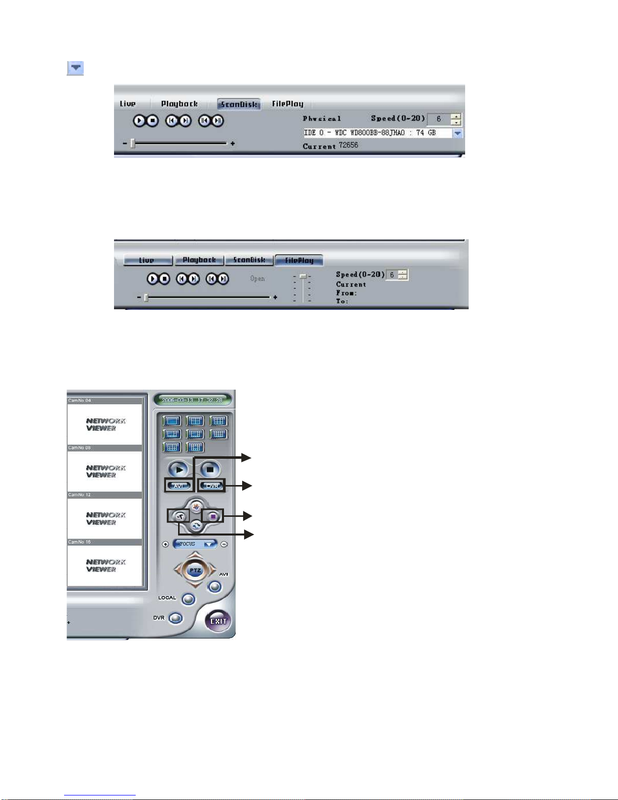
7.5 Scandisk
Connect the HDD that used in the DVR to a PC and then select Scandisk. Scandisk window will display, click
and select one HDD, and then you can play all the video on the HDD.
<Scandisk Menu>
7.6 FilePlay
Press “FilePlay” button, you can see the below picture, press the “open” button play the video file on the
computer.
< Fileplay Menu>
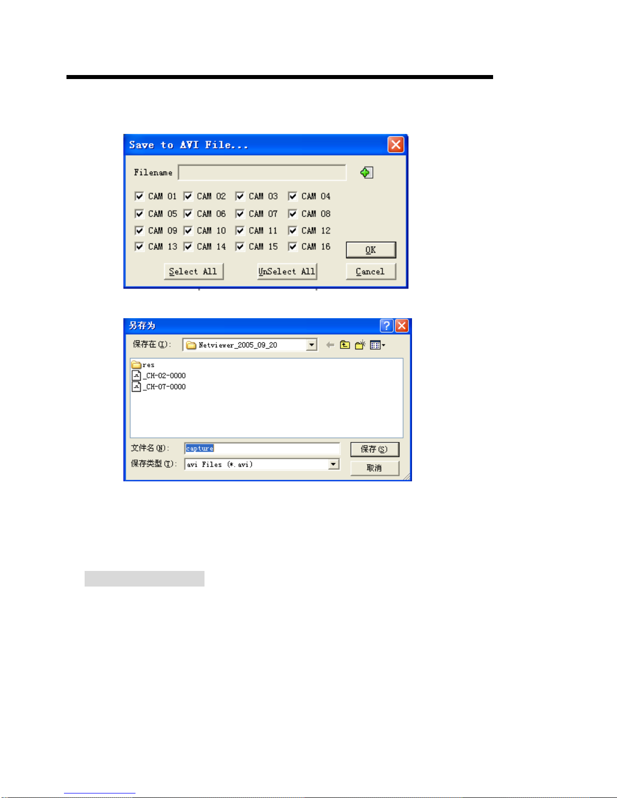
7.7 Save to AVI
Save the video played on the current viewer to AVI.
Press the button, you can see
below the picture
Press the button, you can record
the video by your computer
Press the button, you can remote
DVR record to HDD
Press the button, you can stop
the record DVR
Page 33
16/8 channels DVR art.49146-49148 User’s Manual
33
<Determine the file name and the location where the file is saved>
Click the Save to AVI button and determine the file name, the location and channels to save. Then AVI saving
will start. Click the Save to AVI once more will stop saving.
8. Troubles Shooting
Q: What kind of camera should I buy for this DVR?
A: Any BNC or RCA interface indoor/outdoor/infrared camera will work with the DVR. It doesn’t matter
whether it’s a color or black/white camera. However, web cameras that require a USB interface are not
compatible with the DVR.
Q: What kind of alarm device should I buy for DVR?
A: Most sound alarms are compatible with our DVR.
Page 34

34
Q; I can’t turn on DVR.
A: Make sure that the power cord is plugged in correctly and the power switch on DVR front panel is on.
Q: I see nothing but a blue screen after I turn on DVR.
A: Check the camera input and video output connection on DVR back panel. If you can’t find problem with
these connections, check whether the camera power cable is firmly connected. Make sure the system format
for NTSC and PAL is right.
Q: Why cannot I access Time/Date Set, HDD Format Set or Record Set menu?
A: please stop record or play before you access this menu.
Q: Why cannot I access Record CH Set menu?
A: If the DVR recorded resolution is set CIF mode, the REC CH menu window is not accessible.
Q: Why can’t I playback the video that blue or gray?
A: If you select overwrite the DVR, while the HDD is full, it will overwrite some events. These events that have
been overwriting were in blue or gray.
Q; I push record button, but the DVR does not start recording, why?
A: Push display button to see if there is a hard disk detected, also if the DVR is in schedule mode (there is a
“S” on the screen in yellow) you cannot start recording by push record button, you have to push schedule
button again to cancel schedule mode.
Q: what kind of hard disk drive should I purchase to make the DVR run?
A: Any PC compatible IDE, ATA hard disk drive will work.
Q: Can my desktop PC read the video data on hard disk drive in DVR?
A: Yes, you can use our software to read all video data on hard disk.
Q: When the network connection between DVR and client computer is cut off, why the DVR halts and clock
stops?
A: In case network is cut off abnormally, DVR machine will halts for 20 seconds without response to any
operation of pressing front panel buttons. 20 seconds later, it will restore normal state, but the icon that shows
network status won’t disappear in 10 minutes and in this period client computer cannot connect to the DVR or
enter network menu.
Page 35

16/8 channels DVR art.49146-49148 User’s Manual
35
9. Specification
Video signal NTSC/PAL
Compression M-JPEG
Input 8/16 CH (BNC),75 Ohm,1.0 Vp-p Video signal
Output 1 CH for S-VIDEO
2 CH for monitor (BNC)
Display 720(H)×480(V) (NTSC)
720(H)×576(V) (PAL)
Resolution
Record 720(H)×480(V) (NTSC) 720(H)×576(V) (PAL) FIELD
320(H)×240(V) (NTSC) 320(H)×288(V) (PAL) CIF
Record mode Manual record /motion /schedule /alarm record
Search mode
Time search/event search/
start stop search
Playback
Playback speed 100 fps(PAL)max
120 fps(NTSC)max
Network 1 RJ45 port, live, playback, remote monitoring, Internet Explorer support
Backup CD-RW (optional), USB , network
Update USB
Pan/Tilt/Zoom RS485
Alarm input 8/16 CH
Alarm output 1 CH
Remote control Yes
Language English, French, German, Italian, Spanish, Polish
Other
function
HDD Two max (each over 200GB)
Operating
Temperature
From –5°C to +40°C
Humidity <90% max NON condensing
Power supply Input 100V AC÷ 240V AC; consumption 36÷39.6W
Other
Exterior size
430 (W) × 65 (H) × 385 (D) mm
Designs and specifications are subject to change without notice.
Page 36

36
Via Don Arrigoni, 5 24020 Rovetta S. Lorenzo (Bergamo)
http://www.comelit.it – E mail:
 Loading...