

Page 1
EN
TECHNICAL
MANUAL
Quadra audio/video entrance panel
Art. 4893M
Passion.Technology.Design.
Page 2

Warning
Intended use
This Comelit product was designed for use in the creation of audio and video communication systems in residential,
commercial or industrial settings and in public buildings or buildings used by the public.
Installation
All activities connected to the installation of Comelit products must be carried out by qualified technical personnel, with
careful observation of the indications provided in the Manuals / Instruction sheets supplied with those products.
Wires
Cut o the power supply before carrying out any maintenance procedures.
Use wires with a cross-section suited to the distances involved, observing the instructions provided in the system
manual.
We advise against running the system wires through the same duct as the power cables (230V or higher).
Safe usage
To ensure Comelit products are used safely:
• carefully observe the indications provided in the Manuals / Instruction sheets
• make sure the system created using Comelit products has not been tampered with / damaged.
Maintenance
Comelit products do not require maintenance aside from routine cleaning, which should be carried out in accordance
with the indications provided in the Manuals / Instruction sheets.
Any repair work must be carried out
• for the products themselves, exclusively by Comelit Group S.p.A.,
• for systems, by qualified technical personnel.
Disclaimer
Comelit Group S.p.A. does not assume any responsibility for
• any usage other than the intended use
• non-observance of the indications and warnings contained in this Manual / Instruction sheet.
Comelit Group S.p.A. nonetheless reserves the right to change the information provided in this Manual / Instruction
sheet at any time and without prior notice.
Table of contents
Warning ............................................................................................ 2
Description ....................................................................................... 3
Technical features ........................................................................... 4
Installation ........................................................................................ 5
Changing nameplates ..............................................................................6
Settings ............................................................................................ 7
Programming ................................................................................... 8
Call address programming for 2/4 users and additional external unit 8
Operation with additional external units ................................................9
Operation with switching device 1404 (default) ....................................9
Operation with switching device 1405 ...................................................9
Programming a generic call address ...................................................10
Disabling the COM-RTE contact ..........................................................11
Connections ................................................................................... 12
Door open indication use variant..........................................................12
Variant for using a safety door lock and additional power supply ....12
Using the RC network for door lock filter on relay contacts .............12
System performance and layouts ................................................ 12
2
Page 3
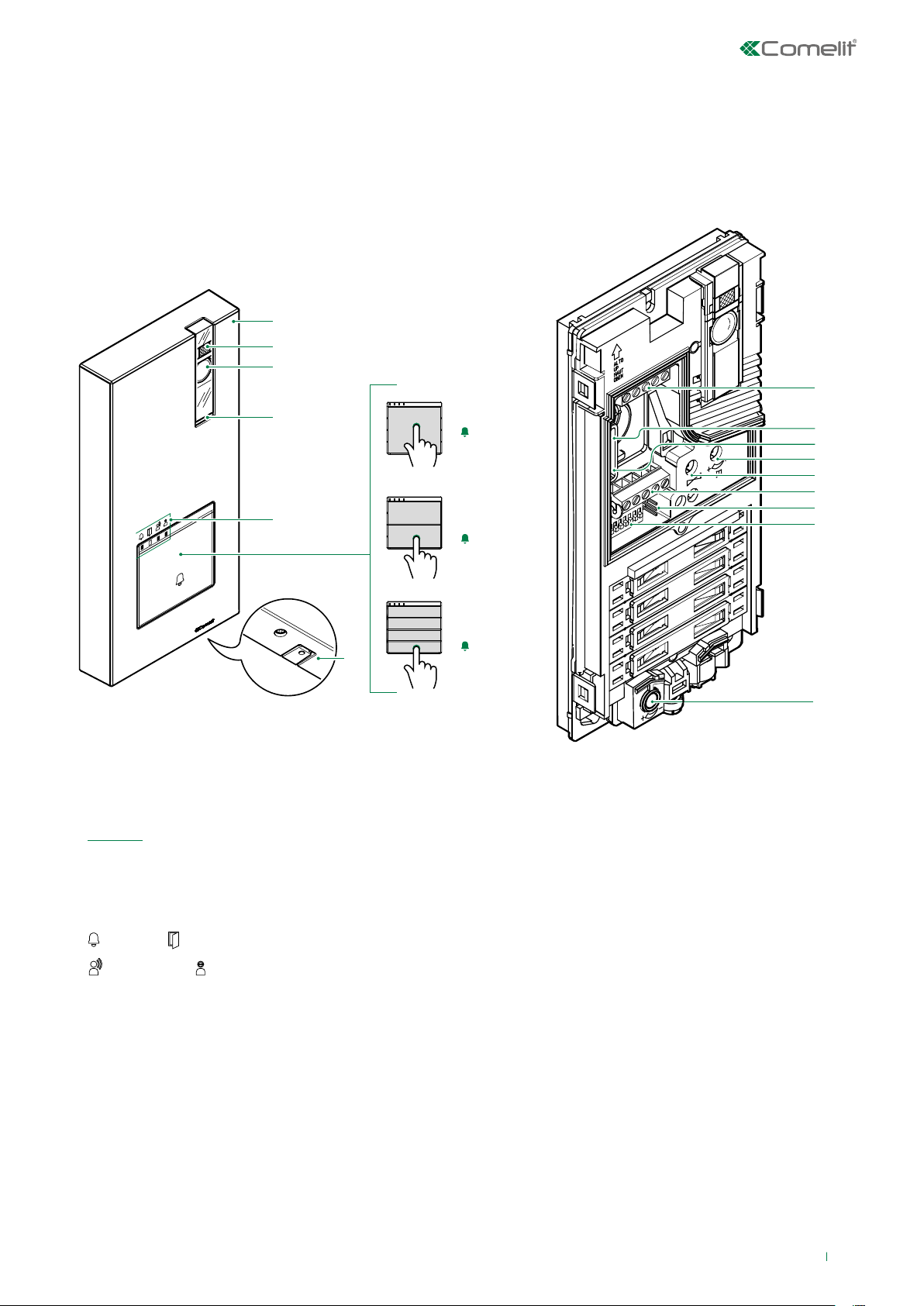
Description
Wall-mounted external unit for Quadra series door entry monitor. Die-cast aluminium front panel, wide-angle colour video
camera and single LED for lighting at night. Mechanical buttons with the option of setting 1 to 4 call buttons via DIP-switch.
Indicator LED for call sent, lock-release activated, audio activated and system busy. Loudspeaker volume adjustment and
audio balancing. Bus line power supply.
1.
2.
3.
8.
4.
5.
6.
7.
1. Die-cast aluminium cover
2. Camera lighting LED set by default to activate in response
to a call (can be disabled by setting DIP 7 to ON, see
Settings)
3. Wide-angle colour camera
4. Loudspeaker
5. Indicator LED
call sent / lock-release activated
audio active / system busy
6. Call button 1 / 2 / 4 users
7. Microphone
1
1
2
1
2
3
4
8. Terminal block M1
LL bus line connection
RTE request to exit button input
COM common input for RTE and DO contacts
DO door open indication input
9. PR programming input/output switch
10. CNF programming confirmation switch
11. Loudspeaker volume control
12. Audio balance
13. Terminal block M2
SE- SE+ connection for electric door lock
NC relay normally closed contact
NO relay normally open contact
C relay common contact
9.
10.
11.
12.
13.
14.
15.
16.
14. JP1 enabling the RC network for door lock filter on relay
contacts
15. DIP-SWITCH for function programming
16. Microphone volume control
3
Page 4

Technical features
MAIN FEATURES
Type of finish Die-cast aluminium
Audio/video system Yes
Wall-mounted Yes
Lens size (mm) 2,1
Diagonal viewing angle (°) 100
Minimum colour illumination (lux) 1
Power supply Bus
Maximum current absorption (mA) 250
Buttons to call Yes
Total buttons 4
Microphone volume control Yes
Loudspeaker volume control Yes
Operating temperature (°C) -25 ÷ +55
IP protection rating IP54
Vandal Resistant rating (IK code) IK08
Type Monoblock entrance panel
Camera Colors
Clamps LL RTE COM DO SE- SE+C NC NO
HARDWARE SPECIFICATIONS
Visual signalling Ye s
Acoustic signalling Ye s
GENERAL DATA
Product height (mm) 195
Product width (mm) 95
Product depth (mm) 28
COMPATIBILITY
Kit audio/video system Ye s
ELECTRICAL SPECIFICATIONS
Door release (dry contact bridge) Ye s
4
Page 5

Installation
COM
L L
RTE
The camera must not be installed in front of light sources, or in places where the filmed subject is against
the light. In dim environments, we recommend additional lighting is provided.
1
2
1 2 3
1
2
OPEN
1
3
2
163 cm
4
130 cm
4 5
Loudspeaker
Microphone
1
2
1
1
2
JOHN DOE
3
1
2
3
4
Settings
6
You can download the free software (art. 1235A) to print the entrance panel name cards, using the adhesive
pre-cut sheets available in our catalogue (art. 1217A).
5
Page 6

3
4
JOHN DOE
MR. SMITH
• Before securing the screw, make sure that you do not need to program the external unit and make sure
that the metal front panel does not rub against other metal parts, with consequent risk of damage to its
insulating coating.
• While the system is running, take care not to accidentally call users when replacing the nameplate labels.
3
CLACK!
CLACK!
JOHN DOE
2
JOHN DOE
1
7 8
To ensure that the product remains water-tight, make sure that the fixing procedure is carried out correctly.
Changing nameplates
1
seepage
risk!
1
1
2
CLOSE
A
PRESS
1
2
JOHN DOE
MR. SMITH
2
3
B
6
1
JOHN DOE
Page 7

Settings
Set the DIP-switches of S1 corresponding to the function that you want to programme as shown in the table below.
DIP-SWITCH FUNCTION
The lock-release relay and the second relay are controlled by 2 separate buttons (e.g. lockrelease button and actuator button)
DIP 1
The lock-release relay and the second relay are controlled by a single button (e.g. lock-release
button)
*
lock-release activation time: 8 sec
DIP 2
lock-release activation time: 2 sec
*
relay activation time: 8 sec
DIP 3
DIP 4
DIP 5
DIP 6
relay activation time: 2 sec
*
reset wait time: 1 sec
reset wait time: 10 sec
*
Call transmission: triple
Call transmission: single
*
confirmation tones (call, lock-release, relay, audio enabled): disabled
confirmation tones (call, lock-release, relay, audio enabled): enabled
*
Camera lighting LED: disabled
DIP 7
DIP 8
* default
Camera lighting LED: enabled
*
LED lighting of name-holder front panels: OFF
LED lighting of name-holder front panels: ON
*
7
Page 8

Programming
Call address programming for 2/4 users and additional external unit
Take note of the DIP-switch settings. Enter programming mode.
1
On the DIP-switch, set the code corresponding to the function you want to program as shown in the table.
2
CODE DIP-SWITCH ON FUNCTION
1 1 Button 1 enabled with call address 1 (default)
2 2 Buttons 1-2 enabled with call addresses 1-2
4 3 Buttons 1-2-3-4 enabled with call addresses 1-2-3-4
8 4
16 5 Secondary Quadra with digital switching device art. 1405
32 6 Main Quadra with digital switching device art. 1405
254 2,3,4,5,6,7,8 Restore default
Single external unit Quadra, or additional external unit connected with digital
switching device art. 1404 (default condition)
1
2
3
Reset the configuration of the DIP-switches
8
4
Page 9

Operation with additional external units
• External unit with switching device art. 1404: default programming to be used with single external unit or with multiple
external units connected with switching device art. 1404.
• Secondary external unit: function to be used in systems with switching device art. 1405 and 2 external units.
• Main external unit: function to be used in systems with switching device art. 1405 and 2 external units.
Operation with switching device 1404 (default)
With the switching device 1404 it is possible to install 2 or more external unit.
In the configuration of art. 1404, the MIN and MAX DIP-switches define respectively the lowest and highest user codes which
can be connected to the riser. For information on setting the desired values, refer to the addressing table.
Separate switching devices for dierent risers must manage code ranges which are not overlapping.
The self-ignition command will activate the camera of the external unit. Further self-ignition commands will toggle between 2
(max) external units, activating them alternately.
For the diagrams, please refer to the Audio/Video kit system section in the system manual
Operation with switching device 1405
With the switching device 1405 it is possible to install only 1 main external unit and 1 secondary external unit.
In “Main external unit” mode, lock-release (or actuator) commands are only executed if the external unit is in call or selfignition mode. The "door-open" function is always deactivated.
In “Secondary external unit” mode, lock release (or actuator) commands are executed if the system is in standby mode or if
the external unit is active.
If the system is in standby mode the first self-ignition command will activate the camera of the secondary external unit.
Further commands will toggle between 2 (max) external units, activating alternately the main external unit and the secondary
external unit.
For the diagrams, please refer to the Audio/Video kit system section in the system manual
9
Page 10

Programming a generic call address
Take note of the DIP-switch settings. Enter programming mode.
1
Set the user code using the DIP-switches in accordance with the addressing table
2
3
4
Reset the configuration of the DIP-switches.
10
Page 11

Disabling the COM-RTE contact
Take note of the DIP-switch settings. Enter programming mode.
1
Set the DIP-switches to position 206 (ON 2,3,4,7,8) in accordance with the addressing table
2
3
4
Reset the configuration of the DIP-switches.
To re-enable the function, repeat the procedure.
11
Page 12

Connections
Door open indication use variant
1209
R
C
SE
SE
NO
NC C
+
-
LL
active input closed for DOOR OPEN signal
Variant for using a safety door lock and additional power supply
T
O
E
M
4893M
D
O
12/24V
AC/DC
R
Local door-opener button
SE
-
SE
+
NO
NC C
C
T
O
LL
E
M
Using the RC network for door lock filter on relay contacts
JP1 JP1 JP1
D
O
System performance and layouts
For further information of system performance and to view installation layouts:
• Audio/video kit for the creation of audio-video systems for individual residences.
12
Page 13

1ª ed.Rev.1 10/2018
cod. 2G40002095
CERTIFIED MANAGEMENT SYSTEMS
www.comelitgroup.com
Via Don Arrigoni, 5 - 24020 Rovetta (BG) - Italy
 Loading...