

Page 1

COLOR CCD, AUTOFOCUS, DAY & NIGHT,
ZOOM CAMERA
ART.40861
Please read this manual thoroughly before use
and keep it for future reference.
Via Don Arrigoni, 5 24020 Rovetta S. Lorenzo (Bergamo)
http://www.comelit.it – E mail: [email protected]
Page 2

ISSUE 3 - OCTOBER 2007
LIMITATION OF LIABILITY
THE INFORMATION IN THIS PUBLICATION IS BELIEVED TO BE ACCURATE IN ALL
RESPECTS, HOWEVER, WE CANNOT ASSUME RESPONSIBILITY FOR ANY
CONSEQUENCES RESULTING FROM THE USE THEREOF. THE INFORMATION
CONTAINED HEREIN IS SUBJECT TO CHANGE WITHOUT NOTICE. REVISIONS OR
NEW EDITIONS TO THIS PUBLICATION MAY BE ISSUED TO INCORPORATE SUCH
CHANGES.
Page 3
WARNINGS
AND CAUTIONS:
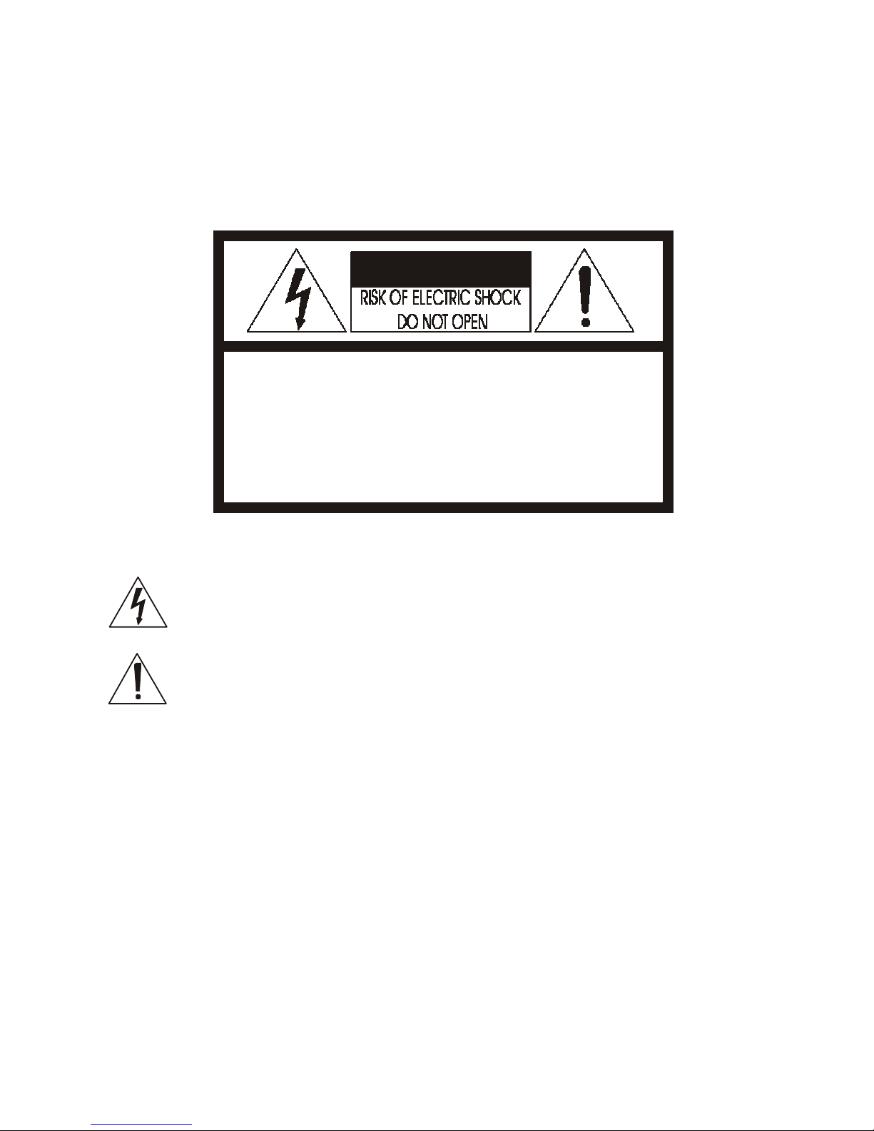
TO REDUCE THE RISK OF FIRE OR ELECTRIC SHOCK, DO NOT EXPOSE THIS PRODUCT TO RAIN OR
MOISTURE. DO NOT INSERT ANY METALLIC OBJECTS THROUGH THE VENTILATION GRILLS OR
OTHER OPENINGS ON THE EQUIPMENT.
CAUTION:
CAU
TION
CAUTION: TO REDUCE THE RISK OF ELECTRIC SHOCK,
DO NOT REMOVE COVER(OR BACK). NO
USER-SERVICEABLE PARTS INSIDE.
REFER SERVICING TO QUALIFIED SERVICE PERSONNEL.
EXPLANATION OF GRAPHICAL SYMBOLS
The lightning flash with arrowhead symbol, within an equilateral triangle, is
intended to alert the user to the presence of uninsulated "dangerous voltage"
within the product's enclosure that may be of sufficient magnitude to constitute a
risk of electric shock to persons.
The exclamation point within an equilateral triangle is intended to alert the user to
the presence of important operating and maintenance (servicing) instructions in the
literature accompanying the product.
PRECAUTIONS
Safety -----------------------------------------
Installation -----------------------------------
Should any liquid or solid object fall into the cabinet,
unplug the unit and have it checked by the qualified
personnel before operating it any further.
Unplug the unit from the wall oulet if it is not going to
be used for several days or more. To disconnect the
cord, pull it out by the plug. Never pull the cord itself.
Allow adequate air circulation to prevent internal heat
build-up. Do not place the unit on surfaces (rugs,
blankets, etc.) or near materials(curtains, draperies)
that may block the ventilation holes.
Height and vertical linearity controls located at the
rear panel are for special adjustments by qualified
personnel only.
Do not install the unit in an extremely hot or
humid place or in a place subject to excessive
dust, mechanical vibration.
The unit is not designed to be waterproof.
Exposure to rain or water may damage the unit.
Cleaning --------------------------------------
Clean the unit with a slightly damp soft cloth.
Use a mild household detergent. Never use
strong solvents such as thinner or benzine as
they might damage the finish of the unit.
Retain the original carton and packing
materials for safe transport of this unit in the
future.
Page 4
- 1 -
FCC COMPLIANCE STATEMENT
FCC INFORMATION :
THIS EQUIPMENT HAS BEEN TESTED
AND FOUND TO COMPLY WITH THE LIMITS FOR A CLASS A DIGITAL
DEVICE, PURSUANT TO PART 15 OF THE FCC RULES. THESE
LIMITS ARE DESIGNED TO PROVIDE REASONABLE PROTECTION
AGAINST HARMFUL INTERFERENCE WHEN THE EQUIPMENT IS
OPERATED IN A COMMERCIAL ENVIRONMENT. THIS EQUIPMENT
GENERATES, USES, AND CAN RADIATE RADIO FREQUENCY
ENERGY AND IF NOT INSTALLED AND USED IN ACCORDANCE WITH
THE INSTRUCTION MANUAL, MAY CAUSE HARMFUL INTERFERENCE
TO RADIO COMMUNICATIONS. OPERATION OF THIS EQUIPMENT IN
A RESIDENTIAL AREA IS LIKELY TO CAUSE HARMFUL
INTERFERENCE IN WHICH CASE THE USER WILL BE REQUIRED TO
CORRECT THE INTERFERENCE AT HIS OWN EXPENSE.
CAUTION :
CHANGES OR MODIFICATIONS NOT EXPRESSLY
APPROVED BY THE PARTY RESPONSIBLE FOR COMPLIANCE
COULD VOID THE USER'S AUTHORITY TO OPERATE THE EQUIPMENT.
THIS CLASS A DIGITAL APPARATUS COMPLIES WITH CANADIAN
ICES-003.
NORME NMB-003 DU CANADA.
CE COMPLIANCE STATEMENT
WARNING
This is a Class A product. In a domestic environment this product
may cause radio interference in which case the user may be required
to take adequate measures.
Page 5

- 2 -
IMPORTANT SAFEGUARDS
1. Read these instructions.
2. Keep these instructions.
3. Heed all warnings.
4. Follow all instructions.
5. Do not use this apparatus near water.
6. Clean only with dry cloth.
7. Do not block any ventilation openings. Install in accordance with the
manufacturer's instructions.
8. Do not install near any heat sources such as radiators, heat
registers, stoves, or other apparatus (including amplifiers) that
product heat..
9. Do not defeat the safety purpose of the polarized or grounding-type
Plug. A polarized plug has two blades with one wider than the other.
A grounding type plug has two blades and a third grounding prong.
The wide blade or the third prong are provided for your safety. If the
provided plug does not fit into your outlet, consult an electrician for
replacement of the obsolete outlet.
10. Protect the power cord from being walked on or pinched
particularly at plugs, convenience receptacles, and the point where
thy exit from the apparatus.
11. Only use attachments/accessories specified by the manufacturer.
12. Unplug this apparatus during lightning storms or when unused for
long periods of time.
13. Refer all servicing to qualified service personnel. Servicing is
required when the apparatus has been damaged in any way, such
as power-supply cord or plug is damaged, liquid has been spilled or
objects have fallen into the apparatus, the apparatus has been
exposed to rain or moisture, does not operate normally, or has been
dropped.
14. CAUTION - THESE SERVICING INSTRUCTIONS ARE FOR USE
BY QUALIFIED SERVICE PERSONNEL ONLY. TO REDUCE THE
RISK OF ELECTRIC SHOCK DO NOT PERFORM ANY SERVICING
OTHER THAN THAT CONTAINED IN THE OPERATING
INSTRUCTIONS UNLESS YOU ARE QUALIFIED TO DO SO.
15. Use Certified/Listed Class 2 power supply transformer only.
Page 6

- 3 -
THIS PAGE INTENTIONALLY LEFT BLANK.
Page 7

- 4 -
TABLE OF CONTENTS
1. INTRODUCTION 1
1.1 THE CAMERA FEATURES 1
2. SYSTEM INSTALLATION 2
2.1 PACKAGE CONTENTS 2
2.2 OPERATION REQUIREMENTS 2
3. PARTS NAME & FUNCTION 3
4. CONNECTION 5
4.1 COLOR LEAD WIRE & COLOR DISPLAY LABEL 5
4.2 EXTERNAL DAY/NIGHT CONTROL 6
4.3 RS-485 CONNECTION 6
4.4 EXTERNAL LENS CONTROL 6
4.5 EXTERNAL A/D KEY CONTROL 7
5. CAMERA ADJUSTMENT 8
5.1 OSD MAIN SCREEN 8
5.2 MAIN MENU 9
6. TROUBLESHOOTING AND MAINTENANCE 15
6.1 TROUBLESHOOTING 15
6.2 MAINTENANCE 15
7. SPECIFICATIONS 16
8. DIMENSIONS 17
Page 8
1
1
Introduction
The Day & Night AutoFocus Zoom color DSP Camera is designed especially for
closed circuit television (CCTV) and security surveillance applications.
1.1
THE CAMERA FEATURES
High performance SONY 1/4" Super HAD CCD
242x zooming capability (Optical : 22x / Digital : 11x)
Ultra Sensitivity Minimum illumination of 0.001 lux @F1.6 (low shutter)
Excellent picture quality
Various picture effects
Support camera control available RS-485
Flexible configuration
DC 12V input
(CAUTION : Use Certified/Listed Class 2 power supply transformer only.)
Function : -
D/N (Day / Night) - Low-SHUT (Digital Slow shutter)
- DIS (Digital Image Stabilize) - WDR (Wide Dynamic Range)
- DNR (Digital Noise Reduction) - AWB (Auto White Balance)
- AE (Auto Exposure) - AGC (Auto Gain Control)
- BLC (Back Light Compensation) - OSD (On Screen Display)
- D-Zoom (Digital Zoom) - NEGA/POSI (Negative / Positive)
- B/W (Black / White) - PIP (Picture In Picture)
- FREEZE (Rear & still picture) - MIRROR (Right, left reverse picture)
IMPORTANT : The user of this camera is responsible for
checking and complying with local, state, and federal laws
and statutes concerning the recording and monitoring of
audio signals.
Page 9
2
2
System Installation
Installation of the camera must be performed by qualified service personnel in
accordance with all local national electrical and mechanical codes.
Perform the following steps to install the camera.
2.1
PACKAGE CONTENTS
Camera
Instruction Manual
12 pin interface cable
A/D Remote Controller (option)
2.2
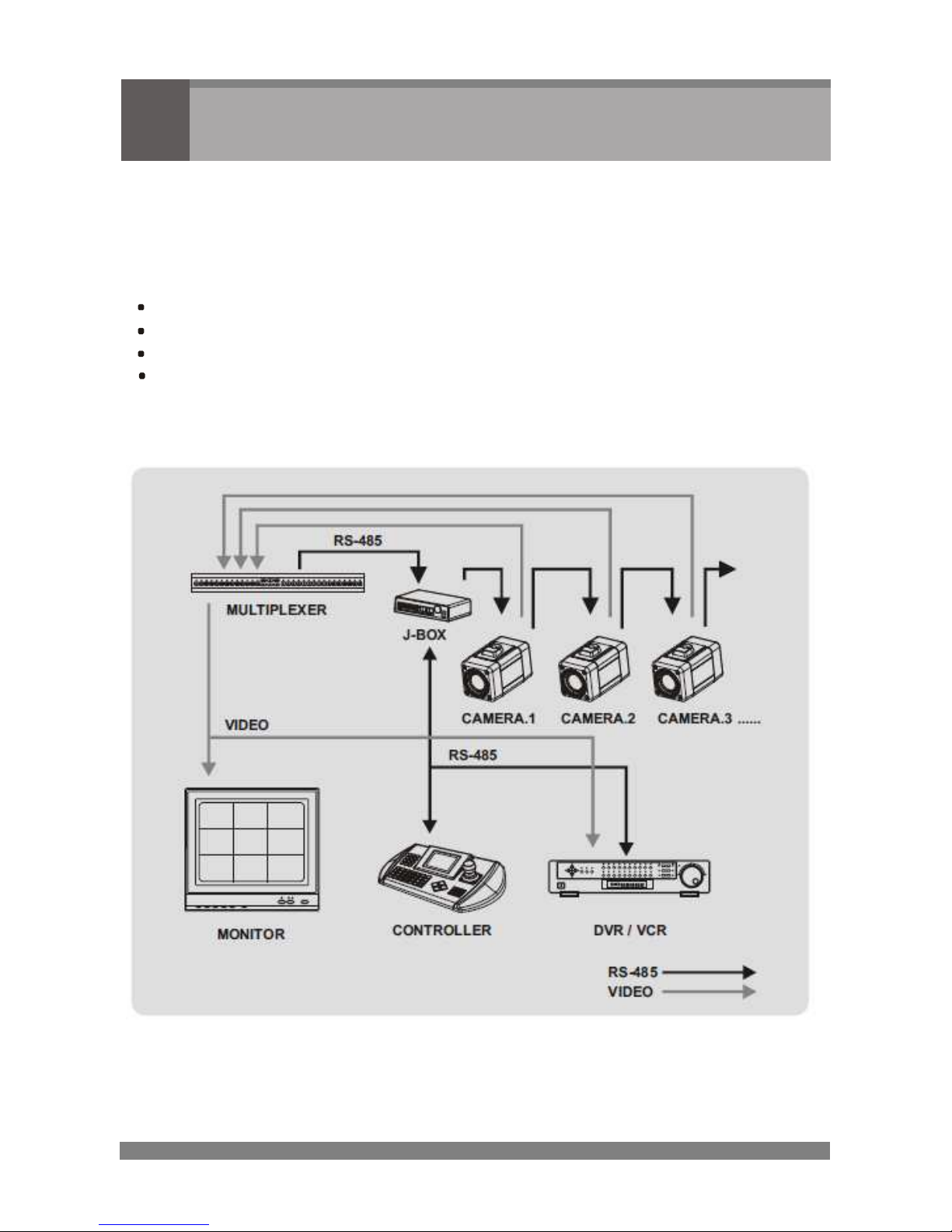
OPERATION REQUIREMENTS
< Typical System Configuration >
Page 10
3
3
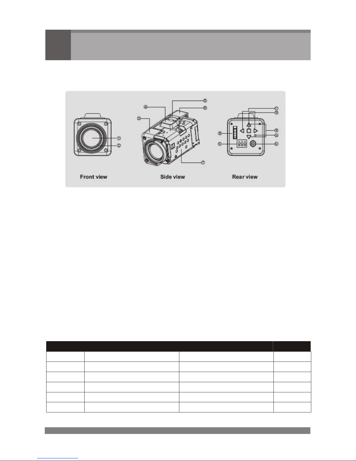
Parts Name & Function
Carefully remove the contents from the box, and verity that nothing was damaged
in shipment.
4 Point - Drilling Position
5021623 A
1 – Day & Night Zoom lens
Integrated lens with 22x optical and 11x digital zoom
2 – Filter mount
Accepts commonly used filters with 37mm diameter
3 – Front case
4 – Mounting adapter
Is used to mount the camera onto a bracket
5 – Case body
6 – Rear case
7 – Camera module
8 – Connector for control interface
12 pin connector
PIN
Description Description
PIN
485-
RS-485(-)
RS-485(+)
485+
TX
RS-232 TXD
IN
RS-232 RXD IN
RX
EXT-OUT
External Out
Ground
GND
EXT-IN
External In
A/D KEY 2
AD2
AD1
A/D KEY 1
Far (-), Near (+)
FOCUS
COM
Common
Tele (-), Wide (+)
ZOOM
Page 11
4
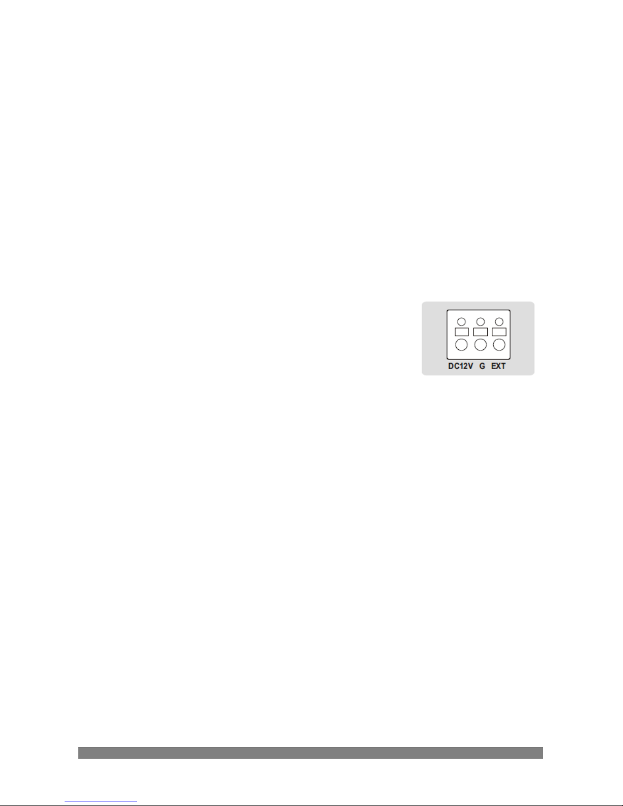
9 – Tele/Wide button
Zoom control: push Wide for wide angle views or Tele to zoom in
10 – Menu button
Menu functions in the OSD display can be controlled when the
OSD menu is activated
11 – Near/Far button
Press the Near side to focus on near objects or the Far side to
Focus on far objects. Focus button are activated in AF off mode
12 – BNC connector
It connects the camera and the monitor or ect.
13 – Power input terminal
Receive DC 12V from the power supply
14 – Power indicator
Is lit when the power is supplied
Page 12
5
4
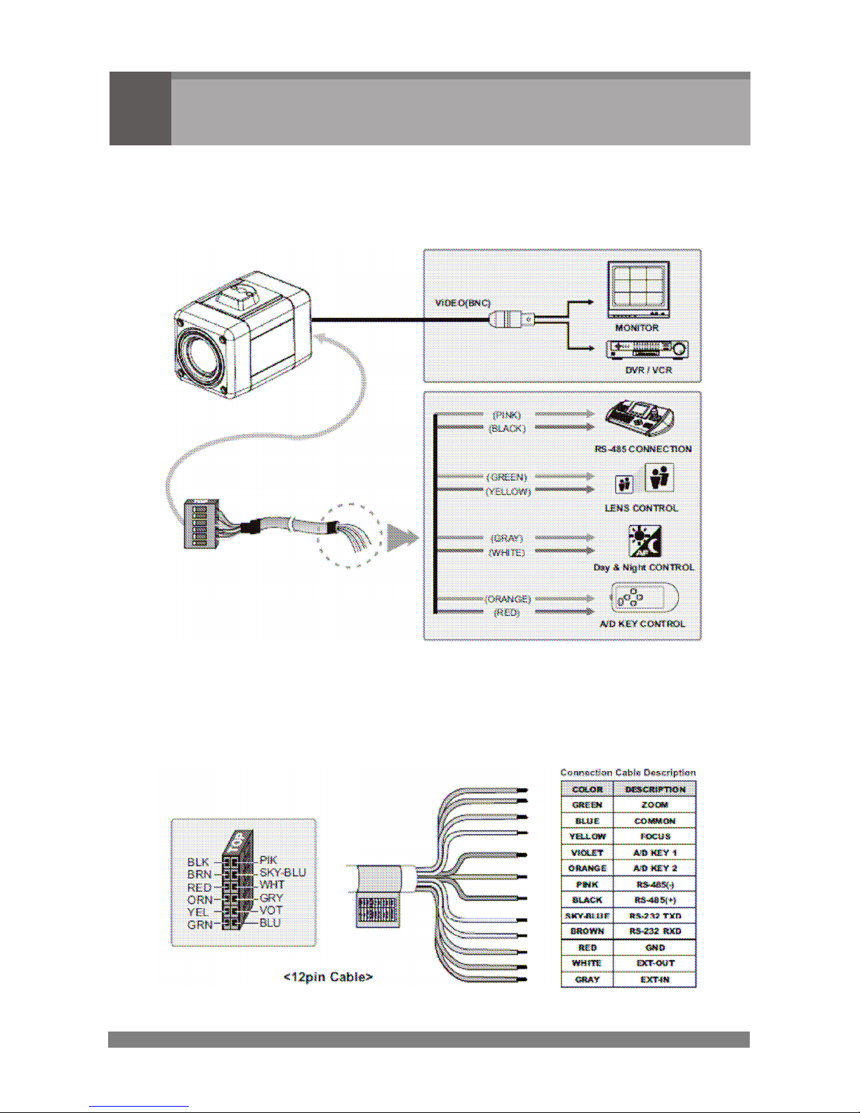
Connection
CAUTION : Do not connect the power cable until all other connections have been
completed. If you complete the whole connection of cameras, then you have
to cut the extra cable.
4.1
COLOR LEAD WIRE & COLOR DISPLAY LABEL
Page 13
6
4.2
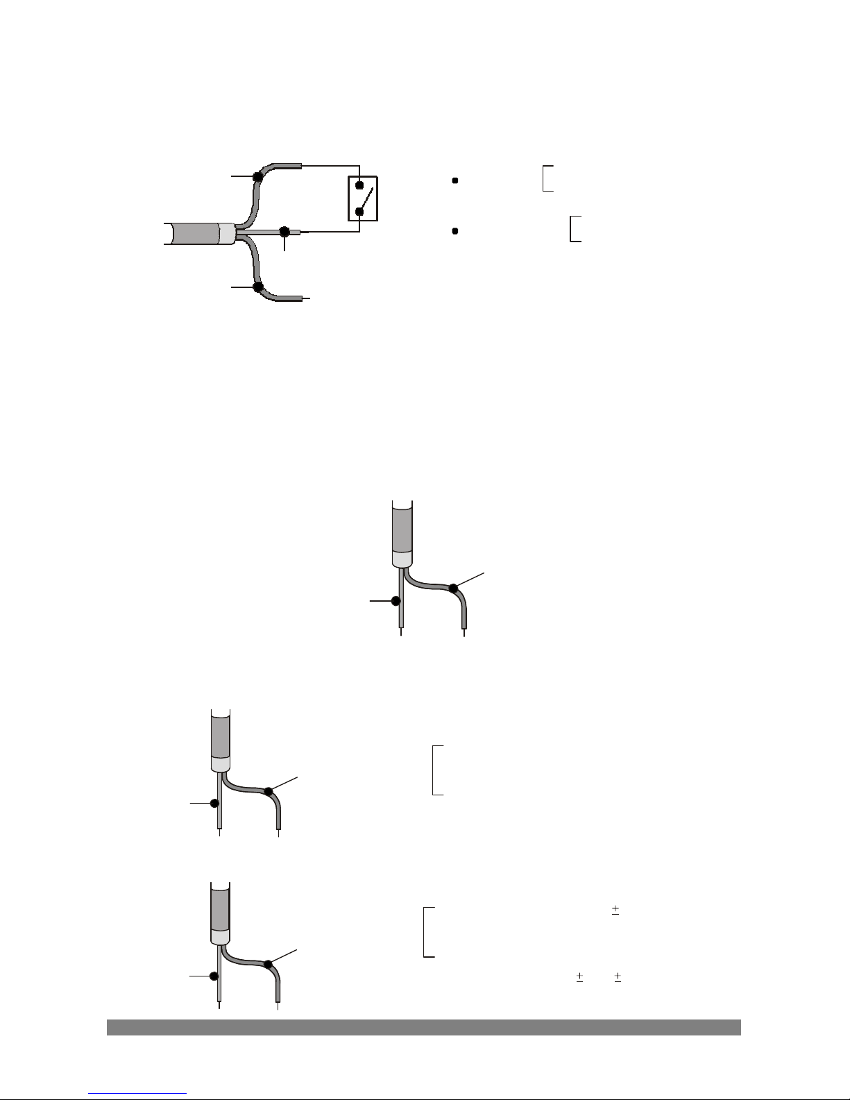
EXTERNAL DAY/NIGHT CONTROL
Connect to an external sensor to receive day/night detection signals.
DAY/NIGHT
GND
External sensor switch ON/OFF
DAY : OPEN
(RED)
EXT-IN
NIGHT : CLOSED
COLOR mode: 0V output
EXT-OUT
(WHITE)
EXT-IN
(GRAY)
EXT-OUT
B/W mode: 5V output
*Note: To validate the sensor inputs, select menu Effect - B/W - EXT
4.3
RS-485 CONNECTION
Connecting to the RS-485 : the camera can be controlled remotely by an
external device or control system, such as a control keyboard, using RS-485
half-duplex. Connect marked Rx+, Rx- to Tx+ and Tx- of the RS-485 control
system.
RS-485
RS-485(-)
(PINK)
RS-485(+)
(BLACK)
4.4
EXTERNAL LENS CONTROL
FOCUS
FOCUS
(YELLOW)
COMMON
(BLUE)
FOCUS
NEAR(+) :
External Power DC ±3V to ±12V (YELLOW)
:
GND (BLUE)
FAR(-)
:
GND (YELLOW)
:
External Power DC ±3V to ±12V BNC (BLUE)
ZOOM
COMMON
(BLUE)
ZOOM
(GREEN)
ZOOM
TELE(+)
:
External DC ±3V to ±12V (GREEN)
:
GND (BLUE)
WIDE(-)
:
GND (GREEN)
:
External DC
3V to
12V (BLUE)
Page 14
7
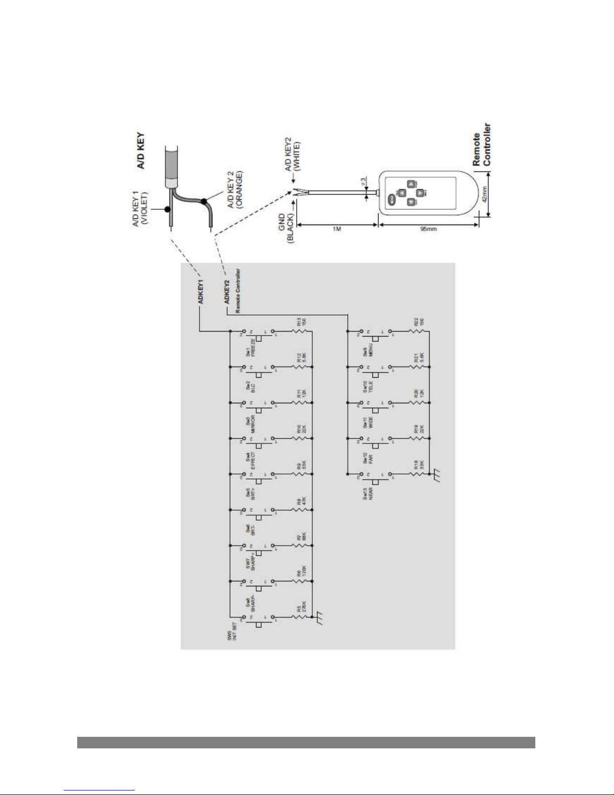
4.5
EXTERNAL A/D KEY CONTROL
External Controller Circuit Schematic
Page 15
8
5
Camera Adjustment
5.1
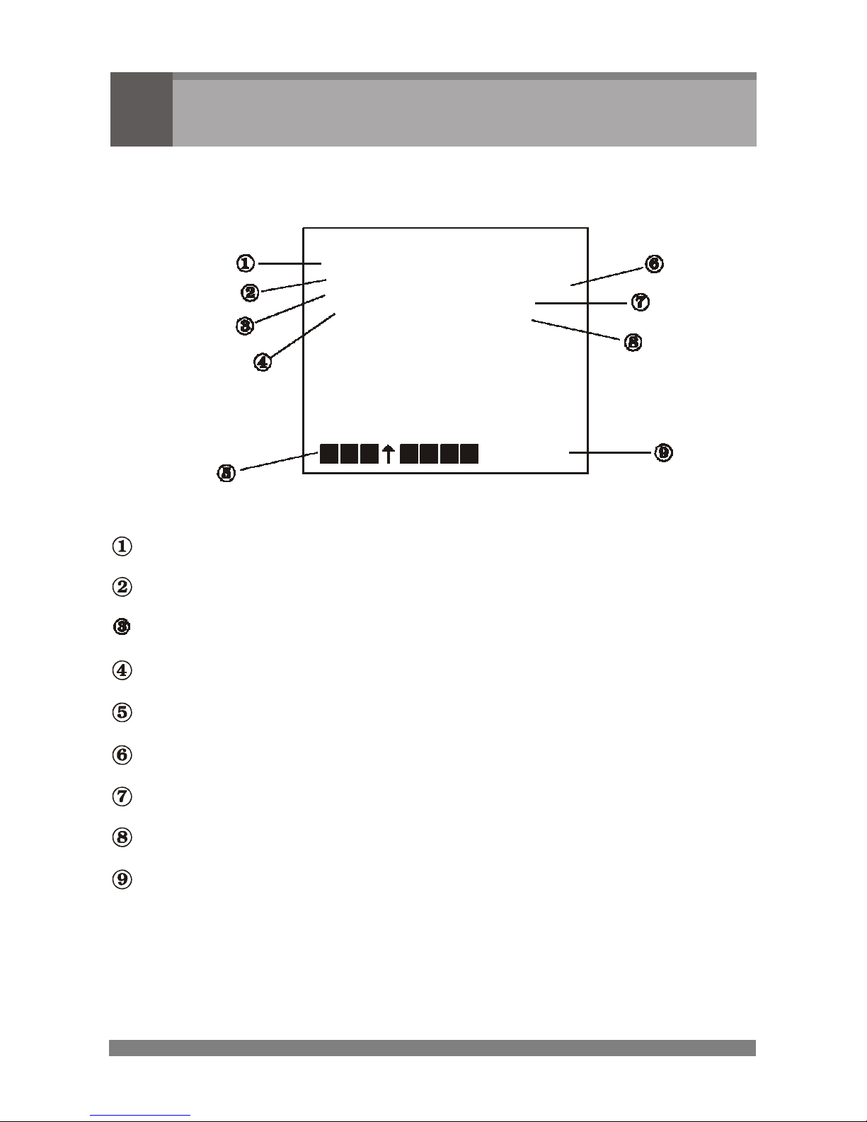
OSD MAIN SCREEN
AF
22X
AEAUTO
AWB
MF
NORMAL
F1.6
0DB
84X
CAM 01
Camera title
Status of the auto exposure
Status of the auto white balance
Status of the focus mode
Status of the zoom position, brightness, or sharpness
Status of the shutter speed
Status of the iris
Status of the AGC (auto gain control)
Camera ID
Page 16
9
5.2
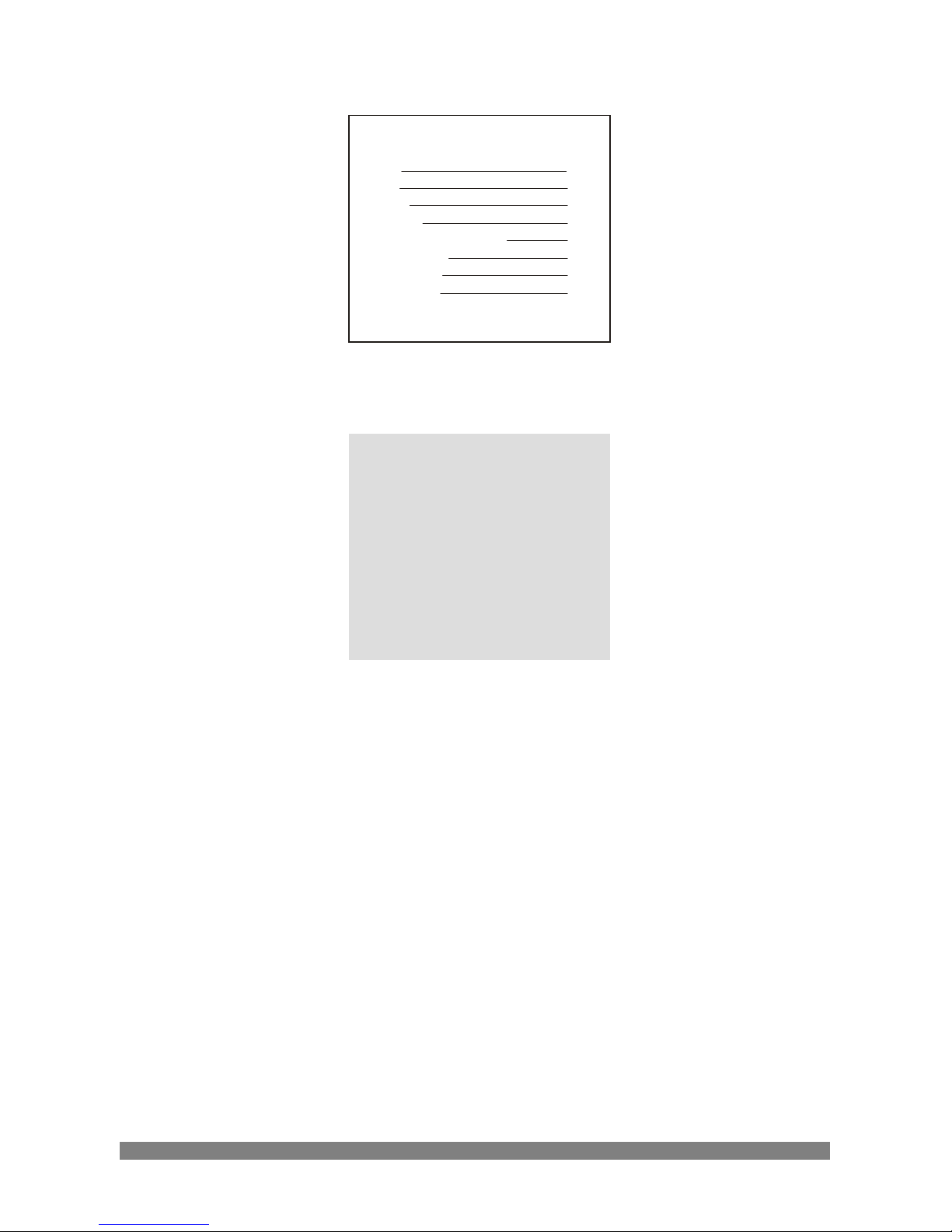
MAIN MENU
<MAIN MENU>
WB
1
AE
2
BLC
3
TITLE
4
DISPLAY/ALARM
5
CAM SET
6
EFFECT
7
PRESET
8
END
5.2.1
WB (White Balance)
<WB>
AWB
INDOOR
OUTDOOR
MANUAL R/B
WAWB
END
AWB Auto white balance mode.
INDOOR Indoor white balance mode.
OUTDOOR Outdoor white balance mode.
MANUAL Manual mode. You can change R and B Gain manually.
For changing R and B gain, use "NEAR" and "FAR" key.
If you save the change, and push the "MENU" key.
WAWB Wide range auto white balance mode.
Page 17

10
5.2.2
AE (Auto Exposure)
<WE>
AUTO
IRIS PRI
SHUTTER PRI
AGC
MANUAL
IRIS
AGC
SHUT
END
LOWSHUT
AUTO Auto exposure mode (Iris, Shutter, AGC)
IRIS PRI Iris priority auto exposure mode.
SHUTTER PRI Shutter priority auto exposure mode.
AGC Auto gain control on/off.
MANUAL Manual exposure mode (Iris, Shutter, AGC)
LOW-SHUT Display Low-Shutter mode (Mode can be changed in the
Preset menu)
5.2.3
BLC (Back Light Compensation)
<BLC>
DEFAULT
ADJ TOP
ADJ BOTTOM
LEVEL
OFF
END
DEFAULT Default setting. Center weight BLC.
ADJ TOP You can adjust BLC zone in left and/or top direction.
ADJ BOTTOM You can adjust BLC zone in right and/or bottom direction.
LEVEL You can adjust BLC level (0 ~ +90)
Default value is 30.
OFF BLC off.
Page 18
11
5.2.4
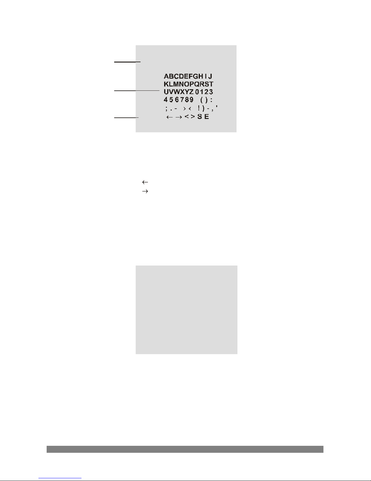
TITLE
A
TITLE
<TITLE MENU>
B
C
CMD
A. TITLE
B. Character Table
C. Command Line
: Move to left
: Move to right
< : Erase a left character
> : Erase a right character
S : Save title
E : End
5.2.5
DISPLAY/ALARM
<DISPLAY/ALARM>
DISP0
DISP1
DISP2
DISP PUSHON
ALARM MODE
DWELL TIME
END
DISP0
DISP1
DISP2
DISP
ALARM MODE
DWELL TIME
Display title and camera ID.
Display title, camera ID and zoom lens position.
Display all camera status.
Off, On and push on (Display on when any key is pressed)
Off, Preset 1~5, B/W (Zoom preset and B/W setup by external-in)
10, 20,....120sec. (Dwell time setup of zoom preset)
Page 19

12
5.2.6
CAM SET
<CAM SET>
ID
BPS
BRIGHTNESS
SHARPNESS
DISTANCE
MAX LOW SHUT
PROTOCOL
SAVE PROTOCOL & BPS
END
ID Select the camera ID (1 ~ 255)
BPS Select serial communication speed
(2400 / 4800 / 9600 / 19200)
BRIGHTNESS Select brightness level (0 ~ +90)
Default value is 30.
SHARPNESS Select sharpness level (0 ~ 15)
Default value is 8.
DISTANCE Select minimum distance in focus between camera and
object. (0.1 / 1.0 / 1.5 / 2.5 / 6.0 m)
MAX LOWSHUT Select maximum Low-shutter value
(x2, x4, x8, x16, x32, x60)
PROTOCOL Select operating protocol.
COMMAND : Camera controlled by RS-232C command.
FASTRAX : Fastrax protocol.
PELCO-D : Pelco-D protocol.
PELCO-P : Pelco-P protocol.
SAVE PROTOCOL & BPS Save protocol and BPS.
*NOTE 1 : You can choose BPS menu appropriate for keyboard protocol.
*NOTE 2 : If you change BPS or PROTOCOL menu, you have to select
PROTOCOL & BPS menu.
Although you change BPS or PROTOCOL menu, the terms of change
is not applied unless you select SAVE PROTOCOL & BPS menu.
Page 20

13
5.2.7
EFFECT
<EFFECT>
D-ZOOM
NEGA/POSI
B/W
MIRROR
PIP
FREEZE
D/N
DNR
END
D-ZOOM Digital Zoom on/off.
NEGA/POGI Select the Negative or Positive picture.
B/W Select Color & B/W picture or EXT mode.
MIRROR Select horizontal reverse picture.
PIP Picture In Picture on/off.
FREEZE Select real and still picture.
D/N Day & Night mode on/off
DNR Digital noise reduction mode on/off
CAUTION : Freeze mode is automatically off during zoom and focus
operation.
Page 21

14
5.2.8
PRESET
<PRESET>
FOCUS
SYNC
INIT
LOAD
SAVE
SHOT
ZOOM PRESET
SET ZOOM PRESET
END
FOCUS Select auto, manual, pushauto mode.
SYNC Select internal or line lock mode.
Sync phase is adjustable in line lock mode.
INIT Camera initialize mode selection(DEFAULT / PRESET).
LOAD Load default or preset parameters of camera
(DEFAULT / PRESET).
SAVE Save preset camera parameters.
SHOT Select Normal, DIS, WDR, or Low-Shutter mode.
DIS(digital image stabilization)
WDR(wide dynamic range)
Low-Shutter(low shutter speed mode)
ZOOM PRESET Select zoom preset number
SET ZOOM PRESET You can set zoom position of zoom preset
CAUTION : In the WDR or Low-Shutter mode, AF performance and Image
quality can be decrease.
DIS is operated on D-Zoom X 2.
DNR is disabled in Freeze, Low-Shutter and WDR mode.
WDR is not effective in freeze status.
Page 22
15
6
Troubleshooting and Maintenance
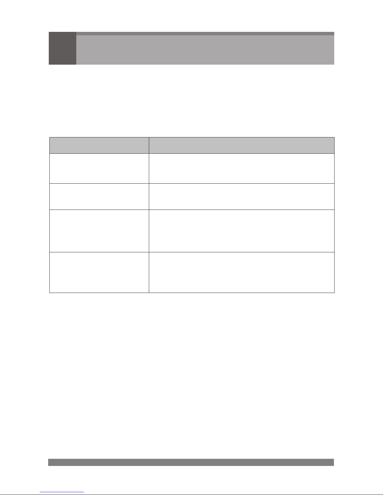
6.1
TROUBLESHOOTING
If problems occur, verify the installation of the camera with the instruction in this
manual and with other operating equipment.
Isolate the problem to the specific piece of equipment in the system and refer to
the equipment manual for further information.
PROBLEM
POSSIBLE SOLUTION
Nothing appears on
the
screen
Are the
power cord and line connection between
the
camera and monitor made properly?
The image on the
screen is dim.
Is the lens dirty?
If so, clean the lens with a soft, clean cloth.
The camera is not
working properly
and the surface of the
camera case is hot.
Is the camera connected to the proper power?
The contrast on the
screen is too weak.
Adjust the contrast feature of the monitor.
Is the camera exposed to strong light?
If so, change the camera position.
6.2
MAINTENANCE
Preventive maintenance allows detection and correction of minor faults
before they become serious and cause equipment failure.
Every three-month, perform the following maintenance.
A. Inspect all connection cables for deterioration or other damage.
B. Clean components with a clean damp cloth.
C. Verify that all the mounting hardware is secure.
Page 23
16
7
Specifications
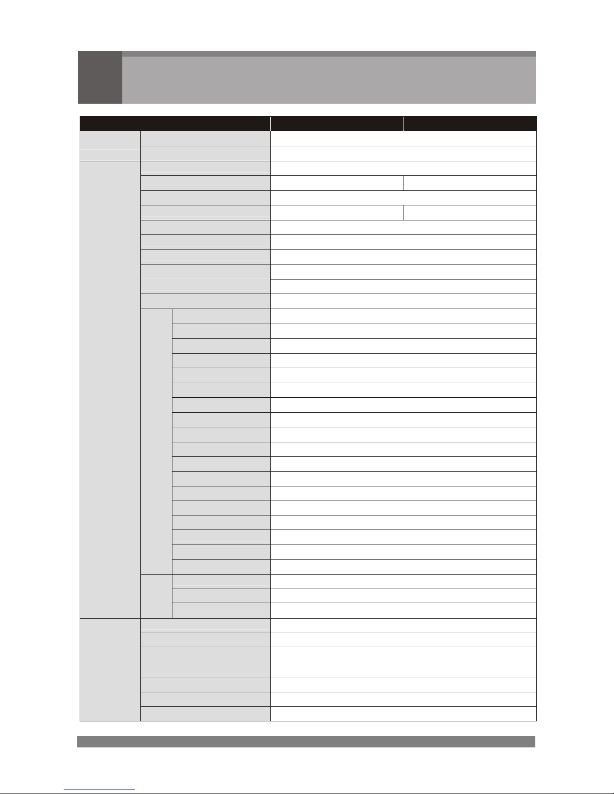
MOD
EL
NTSC
PAL
Power Source
DC 12V
POWER
Power Consumption
5.5 Watts
Image Sensor
1/4" SONY Super HAD CCD
Total Pixels
811(H) x 508(V)
795(H) x 596(V)
Scanning System
2:1 interlace
Scanning Frequency
15,734KHz(H), 59,94Hz(V)
15,625KHz(H), 50Hz(V)
Sync. System
Internal / External (Linelock)
Resolution
480 TV lines(Color), 530 TV lines(B/W)
Min. illumination
0.5 lux(Color), 0.05 lux(B/W), 0.001 lux(Low-shutter)
Video Output
1.0 Vp-p (75 ohm, composite)
S/N Ratio
52dB (AGC off)
Camera Control
RS232, RS485(Fastraxll, Pelco D, Pelco P), A/D key
Focus Mode
Auto / Manual / Push AF
White Balance
AWB / Indoor / Outdoor / Manual / WAWB
Auto Exposure
Auto / Iris PRI / Shutter PRI / AGC / Manual
Iris Control
Auto / Manual (F1.6 ~ F32)
AGC
On / Off (30dB max.)
Shutter Speed
Normal ~ 1/10,000
BLC
Default / ADJ Top / ADJ Bottom / Level / Off
Title
A ~ Z / 0 ~9
Display
On / Off / Push On (DISP0 / DISP1 / DISP2)
CAM ID
001 ~ 255
BPS
2400 / 4800 / 9600 / 19200
Brightness
0 ~ 90 steps
Sharpness
0 ~ 15 steps
Distance
0.1M / 1.0M / 1.5M / 2.5M / 6.0M
Low Shutter
x2 ~ x60
Effect
D&N, D-Zoom, Nega/Posi, B/W, Mirror, PIP, Freeze, DNR
Preset
INIT / LOAD / SAVE
F
U
C
N
T
I
O
N
SHOT
Normal / DIS / WDR / Low-shutter
Zoom Ratio
Optical x22, Digital x11 Zoom (Video AF)
Focus Length
f = 3.9 mm ~ 85.8 mm
GENERAL
L
E
N
S
Aperture Ratio
F1.6 (wide) ~ F3.7 (tele)
Power Input
3-pin terminal block
Video Output
BNC connector
Operating Temperature
-10oC ~ +50oC
Operating Humidity
0 ~ 96% (non-condencing)
Storage Temperature
-20oC ~ +60oC
External Dimensions
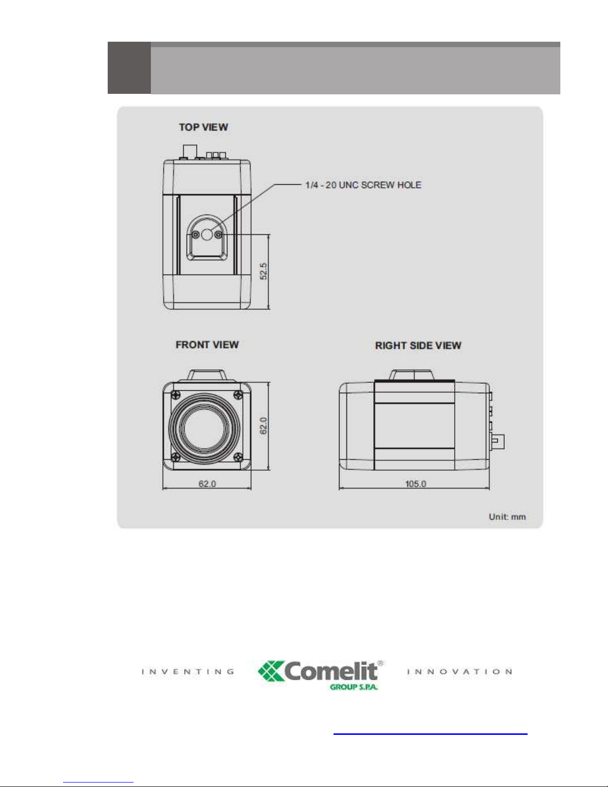
62(W) x 62(H) x 105(D) mm
CONNECTOR
&
ETC.
Weight
315 g
Page 24
8
Dimensions
Via Don Arrigoni, 5 24020 Rovetta S. Lorenzo (Bergamo)
http://www.comelit.it – E mail: [email protected]
 Loading...