

Page 1
INST
R
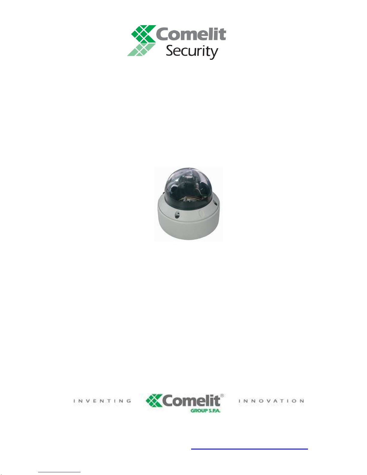
¼” SONY SUPER HAD CCD COLOR DAY & NIGHT
MINITRAX DOME CAMERA
ART. 40797
Please read this manual thoroughly before use
and keep it for future reference.
Via Don Arrigoni, 5 24020 Rovetta S. Lorenzo (Bergamo)
http://www.comelit.it – E mail: [email protected]
Page 2
WARNINGS AND CAUTIONS
WARNING
TO REDUCE THE RISK OF FIRE OR ELECTRIC SHOCK, DO NOT EXPOSE THIS PRODUCT TO RAIN OR
MOISTURE. DO NOT INSERT ANY METALLIC OBJECT THROUGH THE VENTILATION GRILLS OR
OTHER OPENINGS ON THE EQUIPMENT.
CAUTION
Explanation of graphical symbols
The lightning flash with arrowhead symbol, within an equilateral triangle, is
intended to alert the user to the presence of uninsulated “dangerous voltage”
within the product’s enclosure that may be of sufficient magnitude to
constitute a risk of electric shock to person.
The exclamation point within an equilateral triangle is intended to alert the
user to the presence of important operating and maintenance (servicing)
instructions in the literature accompanying the product.
The user is obliged to inform himself and to conform himself to the national and local rules concerning the
monitoring and the audio and video recording. Nobody else will consequently be held responsible for an improper
use of this system which could break the laws in force.
Page 3

ISSUE 1 - JULY 2007
LIMITATION OF LIABILITY
THE INFORMATION IN THIS PUBLICATION IS BELIEVED TO BE ACCURATE IN ALL
RESPECTS, HOWEVER, WE CANNOT ASSUME RESPONSIBILITY FOR ANY
CONSEQUENCES RESULTING FROM THE USE THEREOF. THE INFORMATION
CONTAINED HEREIN IS SUBJECT TO CHANGE WITHOUT NOTICE. REVISIONS OR
NEW EDITIONS TO THIS PUBLICATION MAY BE ISSUED TO INCORPORATE SUCH
CHANGES.
Page 4

Important Safeguards
1. Read Instructions
All the safety and operating instructions should be read before the appliance is operated.
2. Retain Instructions
The safety and operating instructions should be retained for future reference.
3. Cleaning
Unplug this equipment from the wall outlet before cleaning it. Do not use liquid aerosol cleaners. Use a damp soft cloth for
cleaning.
4. Attachments
Never add any attachments and/or equipment without the approval of the manufacturer as such additions may result in the risk
of fire, electric shock or other personal injury.
5. Water and/or Moisture
Do not use this equipment near water or in contact with water.
6. Placing and Accessories
Do not misplace this equipment other than upright position. This equipment has an open frame SMPS (Switching Mode Power
Supply), which may cause a fire or electric shock if anything is inserted into the unit through the ventilation holes on the side
of the equipment.
Do not place this equipment on an unstable cart, stand or table. The equipment may fall, causing serious injury to a child or
adult, and serious damage to the equipment.
This equipment and cart combination should be moved with care. Quick stops, excessive force, and uneven surfaces may
cause the equipment and cart combination to overturn.
7. Power Sources
This equipment should be operated only from the type of power source indicated on the marking label. If you are not sure of
the type of power, please consult your equipment dealer or local power company.
8. Power Cords
Operator or installer must remove power and TNT connections before handling the equipment.
9. Lightning
For added protection for this equipment during a lightning storm, or when it is left unattended and unused for long periods of
time, unplug it from the wall outlet and disconnect the antenna or cable system. This will prevent damage to the equipment
due to lightning and power-line surges.
10. Overloading
Do not overload wall outlets and extension cords as this can result in the risk of fire or electric shock.
11. Objects and Liquids
Never push objects of any kind through openings of this equipment as they may touch dangerous voltage points or short out
parts that could result in a fire or electric shock. Never spill liquid of any kind on the equipment.
Page 5

12. Servicing
Do not attempt to service this equipment yourself. Refer all servicing to qualified service personnel.
13. Damage requiring Service
Unplug this equipment from the wall outlet and refer servicing to qualified service personnel under the following conditions:
A. When the power-supply cord or the plug has been damaged.
B. If liquid is spilled, or objects have fallen into the equipment.
C. If the equipment has been exposed to rain or water.
D. If the equipment does not operate normally by following the operating instructions, adjust only those controls that are
covered by the operating instructions as an improper adjustment of other controls may result in damage and will often
require extensive work by a qualified technician to restore the equipment to its normal operation.
E. If the equipment has been dropped, or the cabinet damaged.
F. When the equipment exhibits a distinct change in performance — this indicates a need for service.
14. Replacement Parts
When replacement parts are required, be sure the service technician has used replacement parts specified by the manufacturer
or that have the same characteristics as the original part. Unauthorized substitutions may result in fire, electric shock or other
hazards.
15. Safety Check
Upon completion of any service or repairs to this equipment, ask the service technician to perform safety checks to determine
that the equipment is in proper operating condition.
16. Field Installation
This installation should be made by a qualified service person and should conform to all local codes.
17. Correct Batteries
Warning: Risk of explosion if battery is replaced by an incorrect type. Dispose of used batteries according to the instructions.
18. Tmra
A manufacturer’s maximum recommended ambient temperature (Tmra) for the equipment must be specified so that the
customer and installer may determine a suitable maximum operating environment for the equipment.
19. Elevated Operating Ambient Temperature
If installed in a closed or multi-unit rack assembly, the operating ambient temperature of the rack environment may be greater
than room ambient. Therefore, consideration should be given to installing the equipment in an environment compatible with
the manufacturer’s maximum rated ambient temperature (Tmra).
20. Reduced Air Flow
Installation of the equipment in the rack should be such that the amount of airflow required for safe operation of the equipment
is not compromised.
21. Mechanical Loading
Mounting of the equipment in the rack should be such that a hazardous condition is not caused by uneven mechanical loading.
22. Circuit Overloading
Consideration should be given to connection of the equipment to supply circuit and the effect that overloading of circuits might
have on over current protection and supply wiring. Appropriate consideration of equipment nameplate ratings
23. Reliable Earthing (Grounding)
Reliable grounding of rack mounted equipment should be maintained. Particular attention should be given to supply
connections other than direct connections to the branch circuit (e.g., use of power strips).
Page 6
FCC COMPLIANCE STATEMENT.
FCC INFORMATIONS: THIS EQUIPMENT HAS BEEN TESTED
AND FOUND TO COMPLY WITH THE LIMITS FOR CLASS A
DIGITAL DEVICE, PURSUANT TO PART 15 OF THE FCC RULES.
THESE LIMITS ARE DESIGNED TO PROVIDE REASONABLE
PROTECTION AGAINST HARMFUL INTERFERENCE IN A
RESIDENTIAL INSTALLATION. THIS EQUIPMENT GENERATES,
USE AND CAN RADIATE RADIO FREQUENCY ENERGY AND, IF
NOT ISTALLED AND USED IN ACCORDANCE WITH THE
INSTRUCTIONS, MAY CAUSE HARMFUL INTERFERENCE TO
RADIO COMMUNICATIONS. HOWEVER, THERE IS NO
GUARANTEE THAT INTERFERENCE WILL NOT OCCUR IN A
PARTICULAR INSTALLATION. IF THIS EQUIPMENT DOES
CAUSE HARMFUL INTERFERENCE TO RADIO OR TELEVISION
RECEPTION, THE USER IS ENCOURAGED TO CORRECT THE
INTERFERENCE TO OWN EXPENSES.
CAUTION: CHANGES OR MODIFICATIONS NOT EXPRESSLY
APPROVED BY THE PARTY RESPONSIBLE FOR COMPLIANCE
COULD VOID THE USER’S AUTHORITY TO OPERATE THE
EQUIPMENT.
THIS CLASS A DIGITAL DEVICE COMPLIES WITH CANADIAN
RULES.
CE COMPLIANCE STATEMENT
WARNING:
THIS IS A CLASS A DIGITAL DEVICE. IN A DOMESTIC
ENVIRONMENT THIS PRODUCT MAY CAUSE RADIO
INTERFERENCE, IN WHICH CASE THE USER MAY BE
REQUIRED TO TAKE ADEQUATE MEASURES.
Page 7

1
1
Intr
odu
ction
1.1 Features
The PTZ Dome keyboard controller and the PTZ Dome camera make up
the building blocks for any surveillance/security system. Using multiple
keyboard controllers and multiple dome cameras, no place is too large
for monitoring. Extensible and flexible architecture facilitates remote
control functions for a variety of external switching devices such as
multiplexers and DVRs.
• Auto focus 22X Optical Zoom (11X Digital Zoom)
• Day & Night (Auto / BW / Color / Global)
• Pan 360° Endless Rotation
• 60 Preset Positions
• 4 Tours consist of Preset, the Speed is selectable from 1 to 10
• 4 Auto Scans, the Speed is selectable from 1 to 10
• 8 Area Titles
• Home Function. Camera automatically goes to preset, tour,
autoscan after controller has been die for an amount of time
• 1 Alarm Input (OFF / NC / NO), 1 Alarm Output (OFF / NC / NO)
and 2 Alarm states (momentary, time out)
• Programmable user preferences (preset, tour, auto scan, area title,
alarm, etc.)
• Up to 63 selectable camera addresses
• Built-in RS-485 receiver driver
• Clear bubble with black liner (shelter) for concealing the camera
• Optional tinted bubble, wall mount
• AC 24V or DC 12V
• Use Certified/Listed Class 2 power supply transformer only
Page 8
2
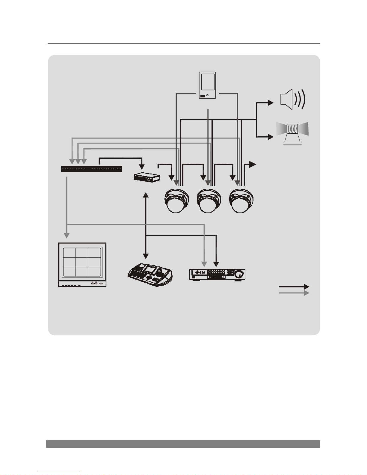
1.2 Operation Requirements
ALARM
INPUT
SENSOR
ALARM
OUTPUT
SIREN
RS-485
FLASHING
LIGHT
MULTIPLEXER
J-BOX
VIDEO
CAMERA.1 CAMERA.2 CAMERA.3 ......
RS-485
MONITOR
CONTROLLER DVR / VCR
RS-485
VIDEO
Typical System Configuration
Page 9
3
G
AI
G
AO
AC+
AC
R+
R
2
Installati
on and C
onne
ction
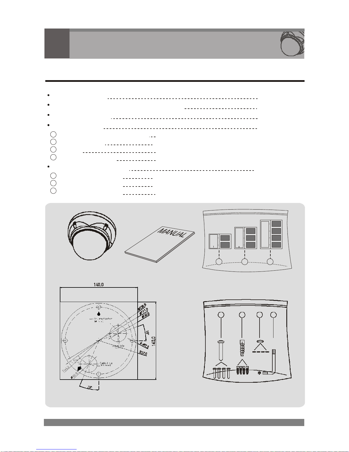
2.1 Package Contents
Dome camera
Instruction manual (This document)
Template sheet
Accessory kit
1
Mounting screws (PH 6 x 35.0) (4)
2
Plastic anchors (4)
3
O-Ring (4)
4
Torx wrench (T-25) (1)
Accessory connector
1
2PIN Terminal Block (1)
2
3PIN Terminal Block (1)
3
4PIN Terminal Block (1)
Dome Camera
Manual
1
2
3
Accessory connector
1
2
3 4
Template sheet
Accessory kit
Page 10
4
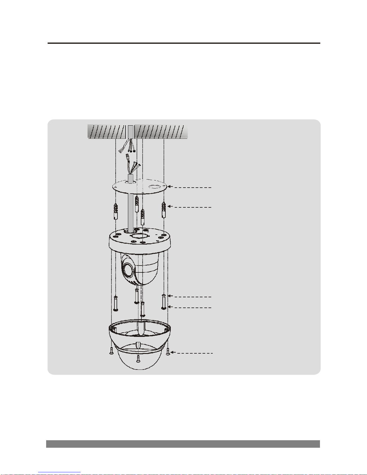
2.2 Base Installation
1. Make mounting holes and cable hole in the place (ceiling) to wich this
dome camera is installed using the supplied template sheet.
Warning: The total mass of the main unit is approx 1.3kg. Check
whether the ceiling to which the Dome Camera is installed
is strong enough to hold the unit mass. If not, the Dome
Camera could fall, causing injury.
Template sheet
Plastic Anchor(4x)
O-Ring(4x)
Mounting Screw(4x)
Torx Screw
2. Extract each wire through the cable hole, and connect the supplied
power, RS-485 and alarm-in-out Terminal Block.
3. Unlock torx screws (4x) the dome cover and fix the dome base firmly
with supplied mounting screws (4x), plastic anchors (4x), O-Rings (4x)
4. Lock the housing cover with torx screws (4x).
Page 11
5
AC+
AC
R+
R
G AI G
AO
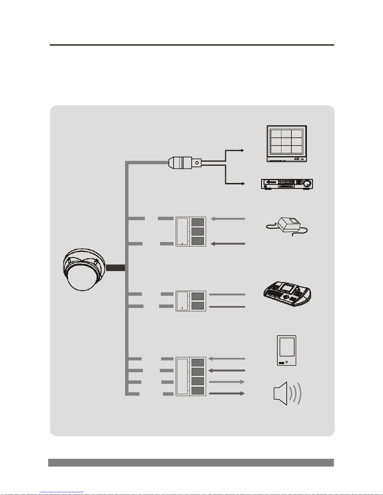
2.3 Basic Configuration PTZ Dome Camera System
CAUTION
Do not connect the power cable until all other connections have been
completed. If you complete the whole connection of cameras, then you
have to cut the extra cable.
VIDEO(BNC)
MONITOR
RED
3PIN
DVR / VCR
WHITE
POWER CONNECTION
GREEN
2PIN
BLUE
RS-485 CONNECTION
BLACK
GRAY
BRAWN
4PIN
SENSOR
YELLOW
SIREN, FLASHING LIGHT
Page 12
6
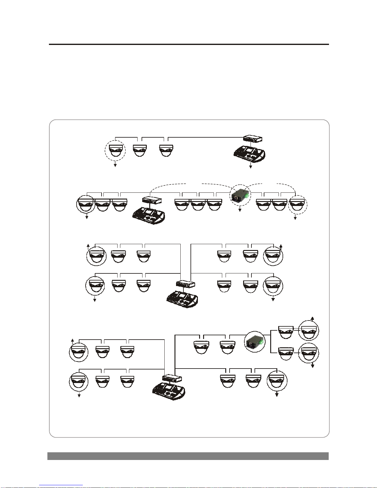
2.4 Setting Dome Camera Termination
The device which is connected at end of line, whether it be a dome
camera or keyboard controller, must have the cable for communication
terminated by setting the “485-TERMINATION” ON at the DOME SETUP
MENU of the OSD (Refer to 3.9-2 485-TERMINATION). Without proper
termination, there is potential for control signal errors. Total length of the
cable for communication should not exceed 1.2km.
Cable for communication
TERMINATION ON
Cable for communication
1.2km
TERMINATION ON
REPEATER/SPLITTER
1.2km
TERMINATION ON
INPUT
TERMINATION ON
OUTPUT
TERMINATION ON
TERMINATION ON
TERMINATION ON
DOME1 PORT
DOME2 PORT
TERMINATION ON
Cable for communication
Cable for communication
TERMINATION ON
INPUT
TERMINATION ON
OUTPUT
TERMINATION ON
TERMINATION ON
TERMINATION ON
DOME1 PORT
DOME2 PORT
TERMINATION ON
Cable for communication
Cable for communication
TERMINATION ON
TERMINATION ON
TERMINATION ON
Termination Diagram
Page 13
7
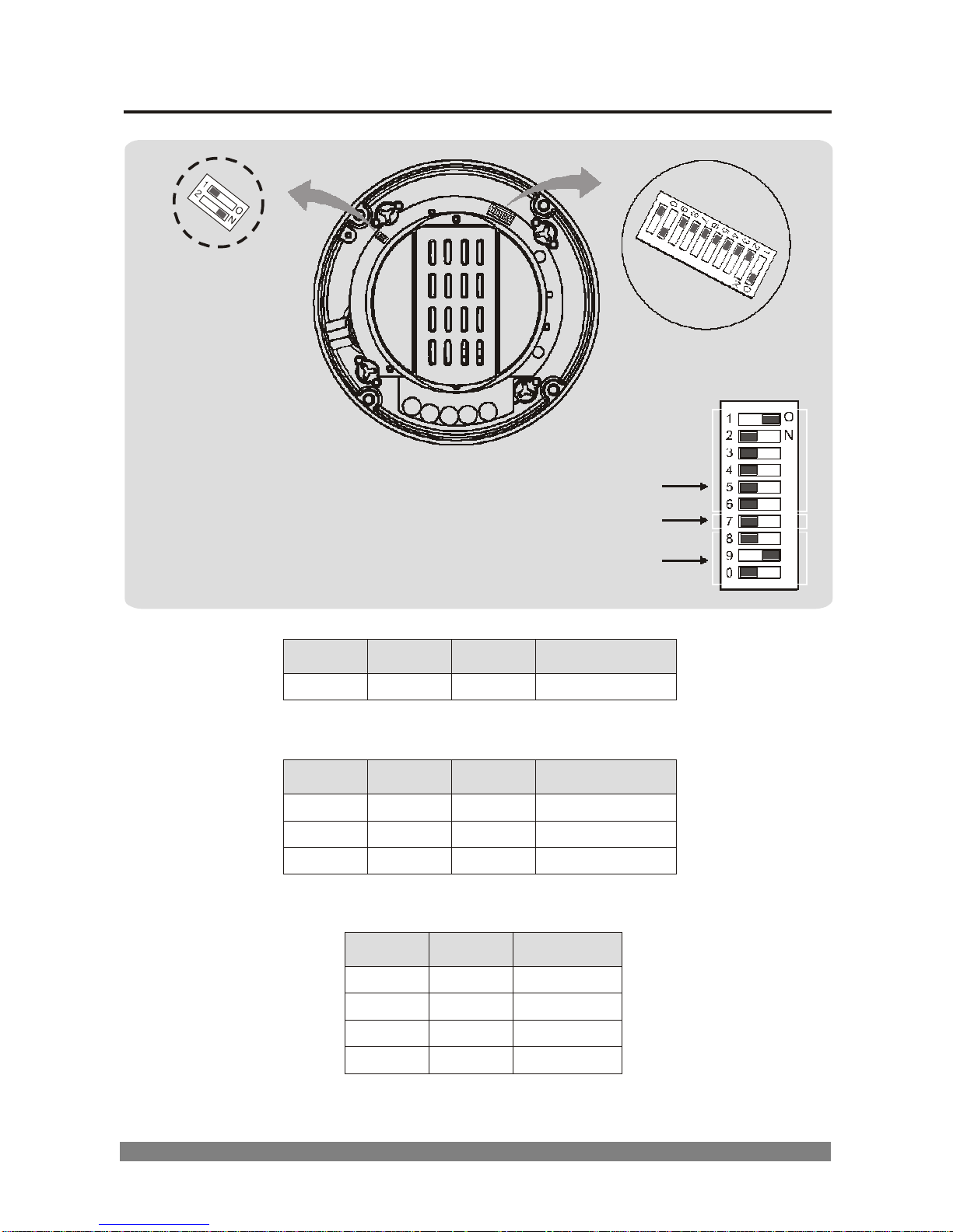
2.5 Setting the Protocol of Dome Camera
Dip Switch2
Dip Switch1
Dome ID Setting
Dome Camera Function
Dome Camera Protocol Function
S/W-No.
ON
OFF
Function
7
NTSC
PAL
NTSC/PAL
Figure 1 - Dome Camera Function Select Switch
No.
8
No. 9
No. 10
Protocol
OFF
ON
OFF
Fastrax-ll
OFF
OFF
OFF
Pelco-D
ON
OFF
OFF
Pelco-P
Figure 2 - Dome Camera Protocol Selection Switches
No. 1
No. 2
BPS
OFF
OFF
2400bps
ON
OFF
4800bps
OFF
ON
9600bps
ON
ON
19200bps
Figure 3 - Dome Camera Baud Rate Setting Switches
Page 14
8
O
N
1 2 3 4 5 6 7 8 9
0
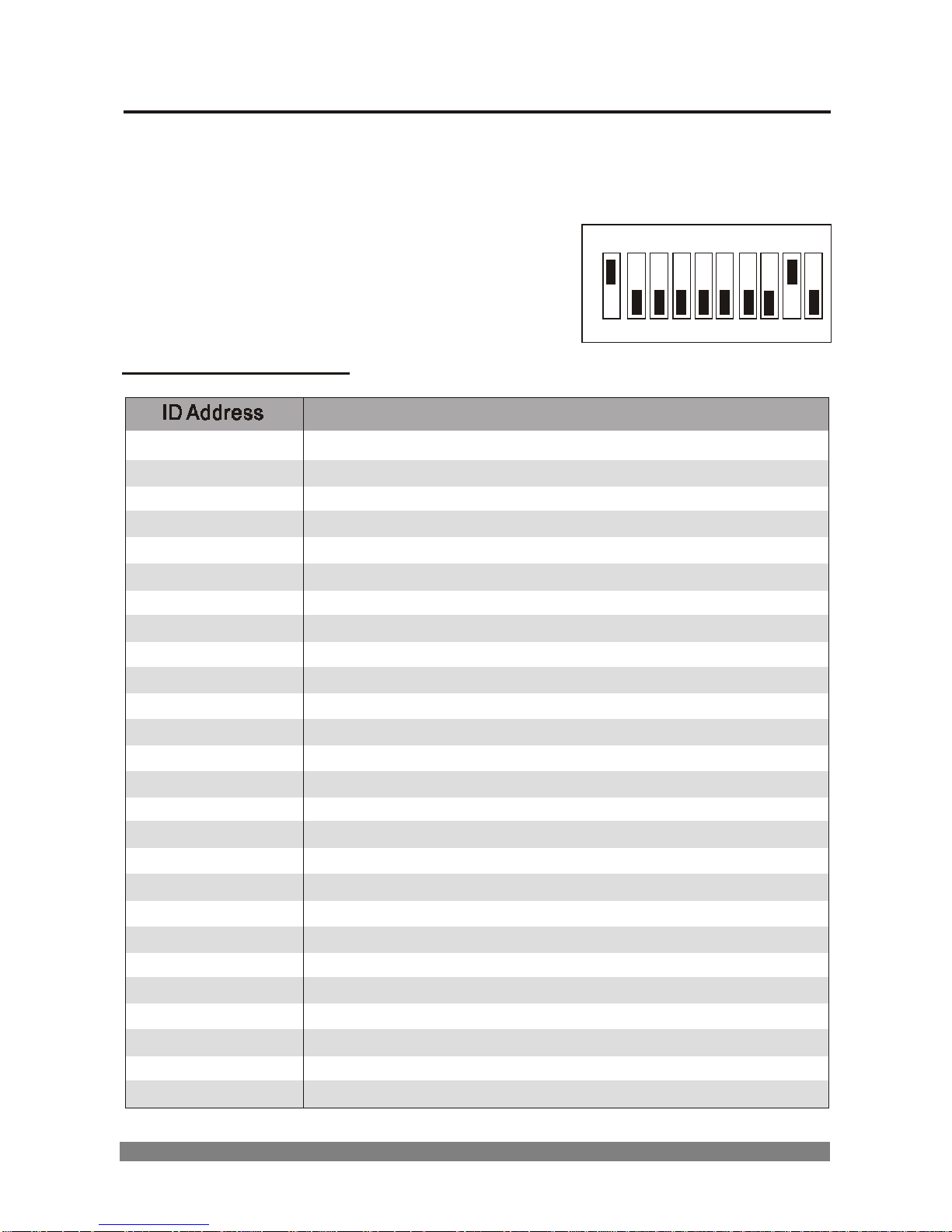
2.6 Setting Address (ID) of Dome Camera
To prevent wrong operation and malfunction, each dome camera must
have a unique address (ID).
The factory default setting is 1.
Refer to Figures 1 and Table 1 for setting the
dome camera address (ID) and
protocol selection.
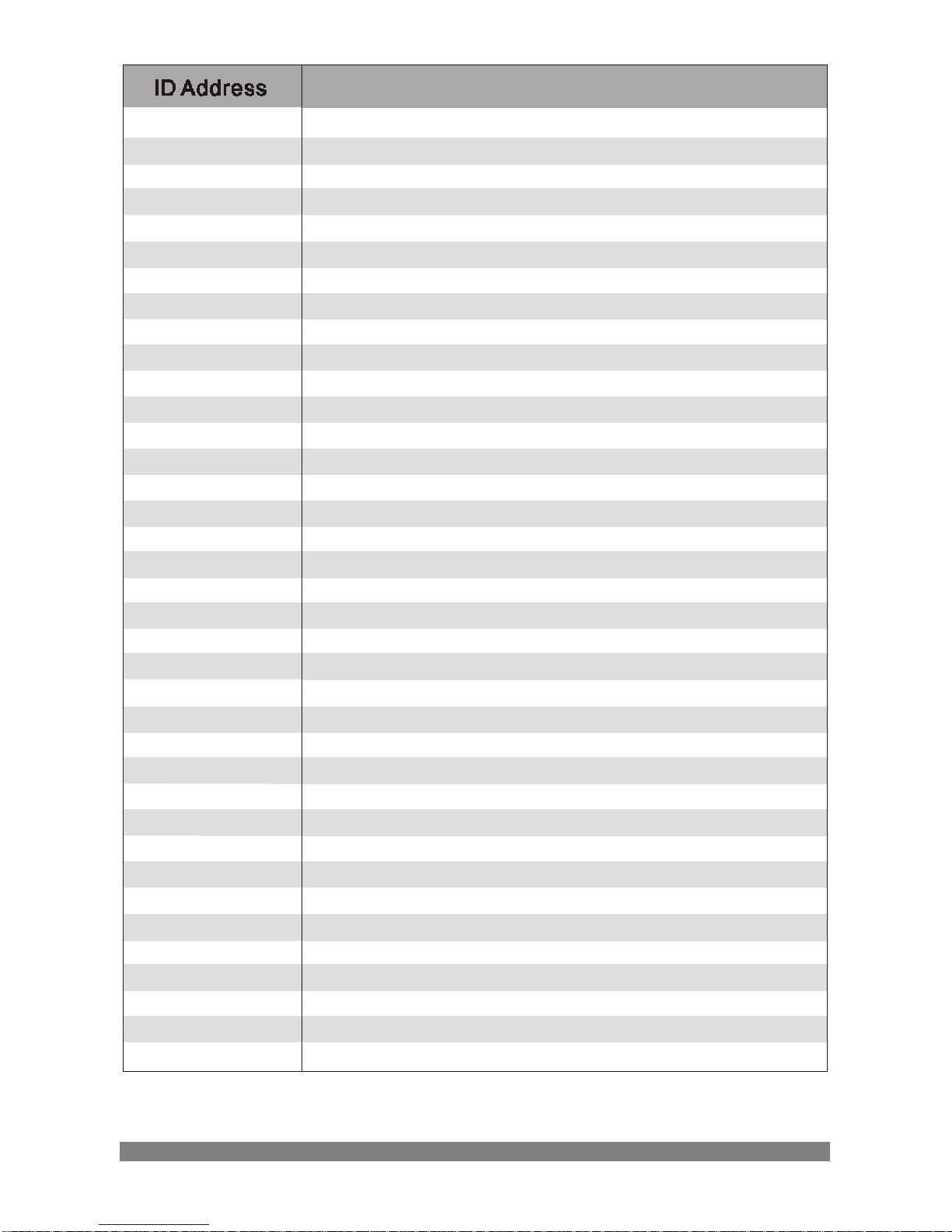
TABLE1 : ID SETTING
1
ON OFF OFF OFF OFF OFF
2
OFF ON OFF OFF OFF OFF
3
ON ON OFF OFF OFF OFF
4
OFF OFF ON OFF OFF OFF
5
ON OFF ON OFF OFF OFF
6
OFF ON ON OFF OFF OFF
7
ON ON ON OFF OFF OFF
8
OFF OFF OFF ON OFF OFF
9
ON OFF OFF ON OFF OFF
10
OFF ON OFF ON OFF OFF
11
ON ON OFF ON OFF OFF
12
OFF OFF ON ON OFF OFF
13
ON OFF ON ON OFF OFF
14
OFF ON ON ON OFF OFF
15
ON ON ON ON OFF OFF
16
OFF OFF OFF OFF ON OFF
17
ON OFF OFF OFF ON OFF
18
OFF ON OFF OFF ON OFF
19
ON ON OFF OFF ON OFF
20
OFF OFF ON OFF ON OFF
21
ON OFF ON OFF ON OFF
22
OFF ON ON OFF ON OFF
23
ON ON ON OFF ON OFF
24
OFF OFF OFF ON ON OFF
25
ON OFF OFF ON ON OFF
26
OFF ON OFF ON ON OFF
Page 15
9
27
ON ON OFF ON ON OFF
28
OFF OFF ON ON ON OFF
29
ON OFF ON ON ON OFF
30
OFF ON ON ON ON OFF
31
ON ON ON ON ON OFF
32
OFF OFF OFF OFF OFF ON
33
ON OFF OFF OFF OFF ON
34
OFF ON OFF OFF OFF ON
35
ON ON OFF OFF OFF ON
36
OFF OFF ON OFF OFF ON
37
ON OFF ON OFF OFF ON
38
OFF ON ON OFF OFF ON
39
ON ON ON OFF OFF ON
40
OFF OFF OFF ON OFF ON
41
ON OFF OFF ON OFF ON
42
OFF ON OFF ON OFF ON
43
ON ON OFF ON OFF ON
44
OFF OFF ON ON OFF ON
45
ON OFF ON ON OFF ON
46
OFF ON ON ON OFF ON
47
ON ON ON ON OFF ON
48
OFF OFF OFF OFF ON ON
49
ON OFF OFF OFF ON ON
50
OFF ON OFF OFF ON ON
51
ON ON OFF OFF ON ON
52
OFF OFF ON OFF ON ON
53
ON OFF ON OFF ON ON
54
OFF ON ON OFF ON ON
55
ON ON ON OFF ON ON
56
OFF OFF OFF ON ON ON
57
ON OFF OFF ON ON ON
58
OFF ON OFF ON ON ON
59
ON ON OFF ON ON ON
60
OFF OFF ON ON ON ON
61
ON OFF ON ON ON ON
62
OFF ON ON ON ON ON
63
ON ON ON ON ON ON
Page 16
10
1 2 3 4 5 6 7 8 9 0
O
N
1 2 3 4 5 6 7 8 9 0
O
N
1
O
2
N
3 4 5 6 7 8 9 0
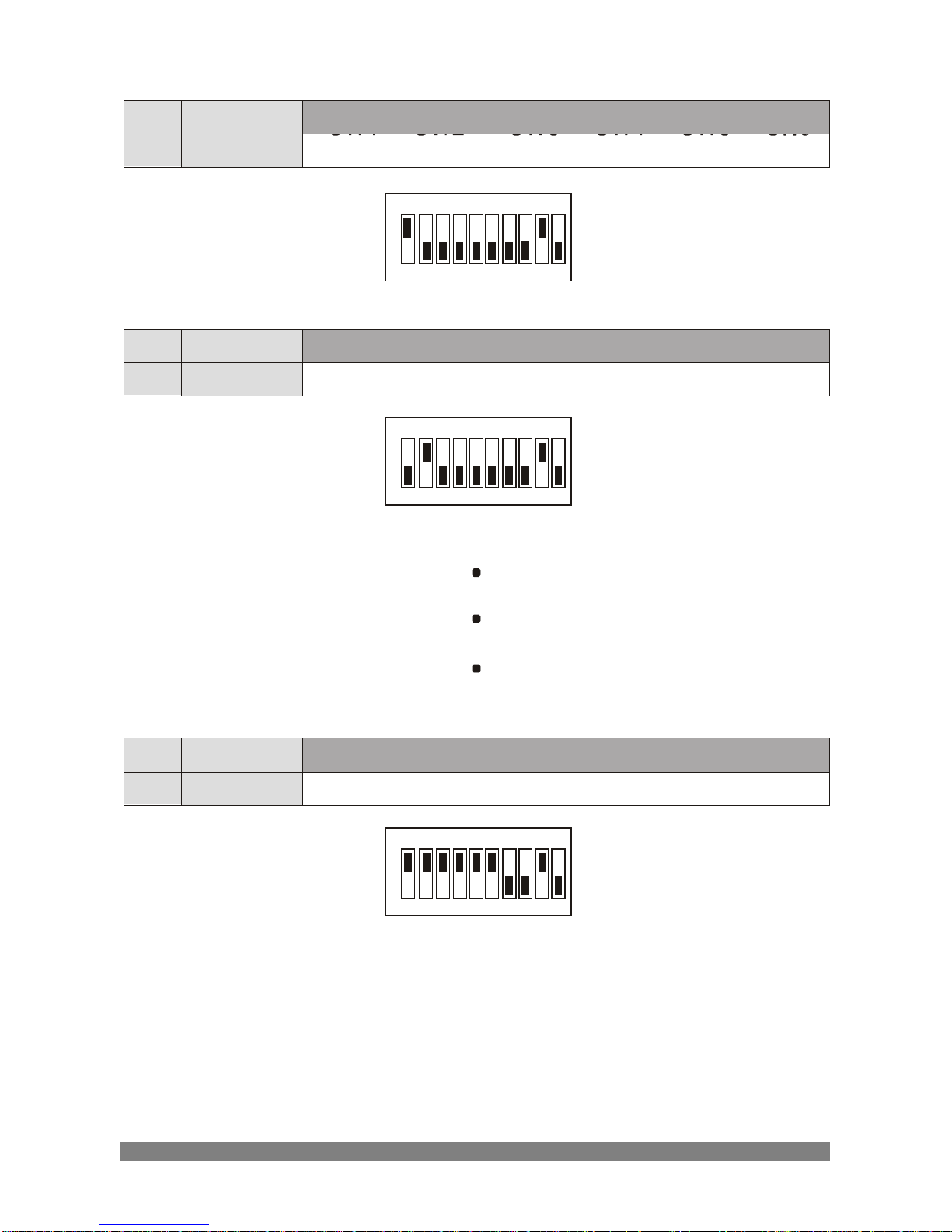
For example :
ID Address
SW1 SW2 SW3 SW4 SW5 SW6
1
ON
OFF OFF
OFF OFF OFF
ID Address
SW1 SW2 SW3 SW4 SW5 SW6
2
OFF ON OFF OFF OFF OFF
ID Address
SW1 SW2 SW3 SW4 SW5 SW6
63
ON ON ON ON ON ON
Page 17

11
2.7 Connecting Wiring
2.7-1 Connecting to the RS-485
The dome camera can be controlled remotely by an external device or
control system, such as a control keyboard, using RS-485 half-duplex.
2.7-2 Connecting Video out connector
Connect the video out(BNC) connector to the monitor or video input of
the DVR.
2.7-3 Connecting Alarms
AI (Alarm In)
You can use external devices to trigger the dome camera to react to
events.
Mechanical or electrical switches can be wired to the AI (Alarm In) and
G (Ground) connectors. See Chapter 3 - Program and Operation for
configuring alarm input.
G (Ground)
NOTE: All the connectors marked G or GND are common.
Connect the ground side of the alarm input and/or alarm output to the
G (Ground) connectors.
AO (Alarm Out)
The dome camera can activate external devices such as buzzers or lights.
Connect the device to the AO (Alarm Out) and G (Ground) connectors.
See Chapter 3 - Program and Operation for configuring alarm output.
2.7-4 Connecting the Power
Connect the power of AC 24V or DC 12V 1A to the dome camera.
When using a DC 12V adapter, connector the positive(+) pole to the
‘AC+’ position and the negative(-) pole to the ‘AC-’ position.
Use Certified / Listed Class 2 power supply transformer only.
Page 18
12
3
Progra
m and O
perati
on
Notice
The symbols shown below mean some action of the joystick controller is required.
/ : move joystick up and down direction.
/ : move joystick left and right direction.
: twist joystick.
KEY
: push defined key.
3.1 Start up Screen
START UP
PROTOCOL : FASTRAX-II
DOME : 01
VX.XX
3.2 Main Menu
MAIN MENU
PRESET
TOUR
AUTO SCAN
AREA TITLE
ALARM
CAMERA SETUP
DOME SETUP
EXIT
/ : move cursor up and down.
: select.
/
ESC
: exit current menu.
The MAIN MENU displays the available all functions of dome. You
should press
MENU
key to display the MAIN MENU.
Page 19
13
3.3 Preset Menu
PRESET MENU
NUMBER: 01
TITLE: ==========
0/1234567890 1/1234567890
* * *
2/1234567890 3/1234567890
4/1234567890 5/1234567890
HOME POSTION: 07
EXIT
306.2 017.4
/ : move cursor up and down.
/ : move cursor left and right or select or change values.
: move dome camera to saved preset point at NUMBER:xx, or
character at
/
ESC
: exit current menu.
If you need to view specific places routinely, you should program presets.
A preset is a programmed video scene with memorized pan, tilt and
zoom settings. Once programmed, selecting the preset number in your
Keyboard or DVR automatically calls up the preset. In addition, presets
may be assigned to the Home Function or Home Position. The dome is
capable of as many as 60 presets when using an external keyboard.
3.3-1 Set Presets at the MENU
1. Move to the NUMBER: 01 and select the Preset Number by using
joystick.
2. Press IRIS OPEN or CTRL button to move the position of the dome
then the message “CONTROL” displays on the screen.
3. Move the dome to the desired position using joystick and set the zoom
level using the zoom in or zoom out.
4. Press IRIS CLOSE or release CTRL button then the message of
“CONTROL” disappears on the screen.
5. The ‘*’ mark is appeared then the Preset is saving automatically.
To insert title, move cursor to TITLE: and set proper title by joystick. If you
don’t select the Title of the preset, the PRESETxx will be displayed.
(xx : the recalled Preset Number)
Page 20

14
You can select the Home Position from the saved presets.
3.3-2 Set ShortCut Preset
1. First of all move the dome to the desired position using joystick and set
the zoom position using the zoom in or zoom out.
2. Press Preset Number you want to save and press PGM and PRST
button in sequence.
For example, if you want to save to number 23, press 2 + 3 + PGM +
PRST button in sequence.
3.3-3 Recall Presets
Press Preset Number and press PRST button.
For example, if you want to recall the Preset 13, press 1 + 3 + PRST
button in sequence.
3.3-4 Home Position
The Home Position is the one of the Saved Presets. If press HOME button,
the PTZ will be go to the Home Position.
Page 21
15
3.4 Tour Menu
TOUR MENU
TOUR : 1
TITLE: ==========
DWELL TIME: 10 SEC
SPEED: 07
== == == == == == == ==
== == == == == == == ==
SAVE
EXIT
/ : move cursor up and down.
/ : move cursor left and right or select or change values.
: change character at TITLE: or change the saved preset
number on the ‘==’ mark
/
ESC
: exit current menu.
3.4-1 Set Tours
1. Move cursor to TOUR: and select tour number by using joystick.
2. To insert the Title of the Tour, move cursor to TITLE: and set proper title
by using joystick. If Title is not selected, TOURxx will be displayed.
(xx : the recalled Tour number)
3. Set Dwell time(10~99 seconds) by using joystick at DWELL TIME.
4. SPEED is selectable from 1 to 10.
5. Move cursor to ‘==’ and select proper preset number by Zoom In / Out.
Each point can be inserted progressively.
6. Move cursor to right at the SAVE menu to save this Tour.
7. Move cursor to right at the EXIT menu to escape this menu.
3.4-2 Delete Tour
1. Move cursor to TOUR: and select tour number to delete.
2. Press HOME button then the selected Tour will be deleted.
3.4-3 Recall Tour
Press Tour Number and press TOUR button. For example, if you want to
recall the Tour 3, press 3 + TOUR button in sequence. When turning the
TOUR ELEMENT on at the OSD DISPLAY MENU, the Preset number
consisting of the recalled Tour will be displayed.
Page 22
16
3.5 Auto Scan Menu
AUTO SCAN MENU
SCAN: 1
TITLE: ==========
START POINT: 000.0 000.0
END
POINT: 000.0 000.0
SCAN DIR. : CW
SPEED: 07
SWAP: OFF
SAVE
EXIT
/ : move cursor up and down.
/ : move cursor left and right or select or change values.
: change character at TITLE:
/
ESC
: exit current menu.
3.5-1 Set Auto Scans
1. Move cursor to SCAN: and select scan number by using joystick.
2. To insert the Title of the Auto scan, move cursor to TITLE: and set proper
title by using joystick. If title is not selected, SCANxx will be displayed.
(xx : the recalled Scan number)
3. Move cursor to START POINT: and press IRIS OPEN or CTRL button
to move the position of the dome then the message “CONROL” displays
on the screen.
4. Move the dome to desired PAN starting point, Tilt point of Auto Scan range
and Zoom postion.
5. Press IRIS CLOSE or release CTRL button then the message of
“CONTROL” disappears on the screen. It is saved automatically.
6. Move cursor to END POINT: Move the dome to desired PAN end point
of Auto Scan range and set end position by pressing IRIS OPEN or
CTRL button. When the setting is completed, press IRIS CLOSE or
release CTRL button.
(Note. At this point, only PAN position will be adjustable.)
7. SCAN DIR. means Auto Scan Direction. CW is Clock Wise and CCW is
Counter Clock Wise.
8. SPEED is selectable from 1 to 10.
Page 23

17
9. SWAP will change the PAN position between START POINT and
END POINT.
10. Select SAVE to save this Auto Scan.
11. Select EXIT to escape this menu.
3.5-2 Set ShortCut Auto Scan1
You can adjustable the Auto Scan 1’s Pan Limit by using the ShortCut
button.
1. First of all move the dome to the desired Pan Start position using
Joystick.
2. Press 6 + 5 + PGM + PRST button in sequence. Then “SAVING:
PAN LEFT AND TILT” is displayed and the message will be disappeared
after a few seconds.
3. To adjust the Pan End Point, move the dome to the desired position by
using the Joystick.
4. Press 6 + 6 + PGM + PRST button in sequence. Then “SAVING:
PAN RIGHT” is displayed and also the message will be disappeared
after a few seconds.
3.5-3 Delete Auto Scan
1. Move cursor to SCAN: and select scan number to delete.
2. Press HOME button then the selected Scan will be deleted.
3.5-4 Recall Auto Scan
Press Auto Scan Number and press SCAN button. For example, if you
want to recall the Scan 2, press 2 + SCAN button in sequence. If you
don’t select title, SCANxx will be displayed. (xx : the recalled Scan number)
Page 24
18
3.6 Area Title Menu
AREA TITLE MENU
AREA: 1
TITLE: AREA1======
START POINT: 000.0
END POINT: 045.0
SAVE
EXIT
/ : move cursor up and down.
/ : move cursor left and right or select or change values.
: change character at TITLE:
/
ESC
: exit current menu.
3.6-1 Set Area Titles
Each area title has default value. There are 8 Area titles that are dividing
360 degrees into 8 equal parts.
1. To modify to another value, move to START POINT: and press
IRIS OPEN or CTRL button to move the position of the dome then the
message “CONTROL” displays on the screen.
2. Move the dome to desired starting point of Area Title range and set start
point.
3. Press IRIS CLOSE or release CTRL button then the message of
“CONTROL” disappears on the screen.
4. The END POINT is the same as the START POINT. But the
END POINT should be larger than the START POINT.
5. Select SAVE to save this Area Title.
6. Select EXIT to escape this menu.
3.6-2 Delete Area Titles
1. Move cursor to AREA: and select area number to delete.
2. Press HOME button then the selected Area will be deleted.
3.6-3 Display Area Titles
When turning the AREA TITLE: of the OSD DISPLAY MENU to ON and
escape this menu, AREAx will be displayed at the screen.
Page 25
19
3.7 Alarm Menu
ALARM MENU
INPUT: NC
OUTPUT: NO
OPTION: TIME OUT
PRESET: 01
HOLDING TIME: 10 SEC
SAVE AND EXIT
EXIT
/ : move cursor up and down.
/ : move cursor left and right or select or change values.
/
ESC
: exit current menu.
3.7-1 Set Alarm
INPUT: NC / NO / OFF
You can select alarm input types here. NC means Normal Close, NO
means Normal Open. If you select input types as OFF, the alarm input is
disregarded.
OUTPUT: NC / NO / OFF
You can select alarm output types here. NC means Normal Close, NO
means Normal Open. If you select output types as OFF, the alarm output
is disregarded.
OPTION: TIME OUT / MOMENTARY
- TIME OUT: The alarm is automatically reset after the alarm duration time
has completed.
- MOMENTARY: When alarm is triggered, the dome will maintain alarm
activation until it is reset manually.
PRESET: xx
The selected preset number is called when the alarm is activated. The
camera remains at the preset position during alarm. After release alarm,
dome camera returns to previous function.
HOLDING TIME: 10~99 SEC
This is activated when the option is TIME OUT and selectable from 10
seconds to 99 seconds.
3.7-2 Release Alarm
If you want to release alarm, press ALRM button at any alarm option.
Page 26
20
3.8 Camera Setup Menu
CAMERA SETUP MENU
FOCUS CONTROL
WB CONTROL
AE CONTROL
L/L CONTROL
PICTURE
NIGHT SHOT CONTROL
INITIALIZE CAMERA
EXIT
/ : move cursor up and down.
: select.
/
ESC
: exit current menu.
FOCUS CONTROL
Controls the focus mode and digital zoom.
WB CONTROL
Controls the white balance mode.
AE CONTROL
Controls the auto exposure options.
L/L CONTROL
Controls access between changing line lock and internal mode.
PICTURE CONTROL
Controls the sharpness, mirror, freeze, nega/posi, DNR, PIP setting.
NIGHT SHOT CONTROL
Controls the IR cutoff filter.
INITIALIZE CAMERA
Resets to the default settings for the camera setup menu only.
Page 27
21
3.8 Camera Setup Menu, continued
3.8-1 Focus Control Menu
FOCUS CONTROL MENU
MODE: AUTO
DISTANCE: 0.1M
DIGITAL ZOOM: OFF
SAVE AND EXIT
EXIT
/ : move cursor up and down.
/ : move cursor left and right or select or change values.
/
ESC
: exit current menu.
MODE: AUTO / MANUAL
You can select focussing mode, auto or manual.
DISTANCE: 0.1 / 1.0 / 1.5 / 2.5 / 6.0 M
Camera doesn’t focus nearer than this range.
DIGITAL ZOOM: ON / OFF
When this is set to OFF, camera zoom uses only optical zoom mode.
Page 28
22
3.8 Camera Setup Menu, continued
3.8-2 WB Control Menu
WB CONTROL MENU
MODE: AWB
RGAIN:
BGAIN:
SAVE AND EXIT
EXIT
/ : move cursor up and down.
/ : move cursor left and right or select or change values.
/
ESC
: exit current menu.
MODE: AWB / INDOOR / OUTDOOR / MANUAL / WAWB
- AWB : Auto White Balance mode.
- INDOOR: Indoor White Balance mode.
- OUTDOOR: Outdoor White Balance mode.
- MANUAL: Manual mode. You can adjust R and B Gain manually.
- WAWB: Wide Range Auto White Balance mode.
R-GAIN: 0 ~ 255
You can adjust the red color gain only in the manual mode.
B-GAIN: 0 ~255
You can adjust the blue color gain only in the manual mode.
Page 29
23
3.8 Camera Setup Menu, continued
3.8-3 AE Control Menu
AE CONTROL MENU
MODE: AUTO
SHOT: NORMAL
SHUTTER:
IRIS:
GAIN:
BRIGHT: 30
BLC MODE: OFF
BLC LEVEL:
SAVE AND EXIT
EXIT
/ : move cursor up and down.
/ : move cursor left and right or select or change values.
/
ESC
: exit current menu.
MODE: AUTO / SHUTTER PRI / IRIS PRI / MANUAL / FLICKERLESS
- AUTO: means all functions are activated automatically.
- SHUTTER PRI(ority): means that you can set only shutter value and
others are controlled automatically.
- IRIS PRI(ority): You can set only iris value and others are automatic in
mode.
- MANUAL: The Shutter, Iris and Gain are adjustable in this mode.
- FLICKERLESS: This function is used to removing flicker when the
format of camera signal does not coincide with power
source frequency being used.
SHOT: NORMAL / LOW-SHUTTER / WDR / DIS
- Low-Shutter means Low Shutter Speed Mode.
- WDR means Wide Dynamic Range
- DIS means Digital Image Stabilization.
SHUTTER: X60 / X32 / X16 / X8 / ... / 2000 / 4000 / 10000
You can set shutter speed in this menu.
IRIS: F1.6 / F2 / F2.8 / F4 / F5.6 / F8 / F11 / F16 / F22 / F32 / CLOSE
You can control lens’s F number in this menu.
GAIN: 0 ~ 30 DB
The value is changeable from 0 to 30.
Page 30

24
BRIGHT: 0 ~ 90
The brightness value is changeable from 0 to 90.
BLC MODE: ON / OFF
The Back Light Compensation is active when ON is set.
BLC LEVEL: 0 ~ 90
The BLC Level is selectable from 0 to 90.
Page 31

25
3.8 Camera Setup Menu, continued
3.8-4 L/L Control Menu
L/L CONTROL MENU
SYNC: INTERNAL
PHASE:
SAVE AND EXIT
EXIT
/ : move cursor up and down.
/ : move cursor left and right or select or change values.
/
ESC
: exit current menu.
MODE: INTERNAL / LINE LOCK
- INTERNAL: Synchronizes camera to an internal crystal. This choice is
recommended if there is noise on the power line.
- LINE LOCK: Synchronizes camera to AC power. This choice eliminates
picture roll in multi-camera systems.
PHASE: PAL(0 ~ 620), NTSC(0 ~ 519)
Optimizes the line lock mode to eliminate picture roll in multiphase power
application.
Page 32
26
3.8 Camera Setup Menu, continued
3.8-5 Picture Menu
PICTURE MENU
SHARPNESS: 08
MIRROR: OFF
FREEZE: OFF
NEGA/POSI: POSI
DNR: ON
PIP: OFF
SAVE AND EXIT
EXIT
/ : move cursor up and down.
/ : move cursor left and right or select or change values.
/
ESC
: exit current menu.
SHARPNESS: 0 ~ 15
The Sharpness can be controlled from 0 to 15 and the default value is 8.
MIRROR: ON / OFF
Video image can be reversed along vertical line.
FREEZE: ON / OFF
The FREEZE is ON, you can see still picture.
NEGA/POSI: NEGA / POSI
You can see the NEGAtive screen or POSItive screen.
DNR: ON / OFF
The DNR means Digital Noise Reduction.
PIP: ON / OFF
The PIP means Picture In Picture. If ON state is selected, the small
screen will be appeared at the lower right corner.
Page 33
27
3.8 Camera Setup Menu, continued
3.8-6 Night Shot Control Menu
NIGHT SHOT CONTROL MENU
D/N MODE: AUTO
D/N LEVEL: HIGH
DELAY: 10 SEC
SAVE AND EXIT
EXIT
/ : move cursor up and down.
/ : move cursor left and right or select or change values.
/
ESC
: exit current menu.
D/N MODE: AUTO / BW / COLOR / GLOBAL
- AUTO: The camera automatically engages the switch from color to b/w
depending on the ambient light, allowing the camera to be effective in
day/night environments.
- GLOBAL: If you press 888 + ENTR(GLBL) in a state of global setting,
every dome will change BW state. And if you press 999 + ENTR(GLBL)
in a state of global setting, every dome will change COLOR state. At this
state, the Dome ID doesn’t matter.
D/N LEVEL: HIGH / MID / LOW
Adjust the AGC Gain when the BW mode turns into the COLOR mode.
This is effective only in case of selecting the AUTO mode.
DELAY: 0 / 10 / 15 / 20 SEC
Adjust the working time of the filter when D/N operated. This is effective
only in case of selecting the AUTO mode.
Page 34

28
3.8 Camera Setup Menu, continued
3.8-7 Initialize Camera
If you run this menu, camera's all setting options are initialized as default
setting.
CAMERA WILL BE INITIALIZED!!
ARE YOU SURE?
NO
YES
Page 35
29
3.9 Dome Setup Menu
DOME SETUP MENU
TILT AUTO FLIP: ON
485-TERMINATION: OFF
ACKNOWLEDGE: ON
AUTO CALIBRATION
PASSWORD
OSD DISPLAY
HOME FUNCTION
INITIALIZE DOME
DOME INFORMATION
SAVE AND EXIT
EXIT
/ : move cursor up and down.
/ : move cursor left and right or select or change values.
/
ESC
: exit current menu.
3.9-1 Tilt Auto Flip
Allows the dome camera to automatically turn 180 degrees when the
camera tilts to its lowest position.
When the camera reaches the floor 90 degree tilt down, it will stop.
Release the joystick handle instantly and then pull down to run the flip
function. The tracking speed will be the same as previous.
3.9-2 485-Termination
The device which in connected at end of line, whether it be a dome camera
or keyboard controller, must have the cable for communication terminated
by setting this menu. Without proper termination, there is potential for
control signal errors. Total length of the cable for communication should not
exceed 1.2km.
3.9-3 Acknowledge
If you select ON, acknowledge will be send to Keyboard or DVR and so on.
If you select OFF, there is no acknowledge.
Page 36
30
3.9 Dome Setup Menu, continued
3.9-4 Auto Calibration Menu
AUTO CALIBRATION MENU
EXECUTION
EXIT
/ : move cursor up and down.
: select.
/
ESC
: exit current menu.
If there is an error on angle of the Camera, just select EXECUTION of the
AUTO CALIBRATION MENU. The motor of the Pan/Tilt will adjust its angle
automatically.
Page 37
31
3.9 Dome Setup Menu, continued
3.9-5 Password Menu
PASSWORD MENU
DISPLAY: OFF
CHANGE PASSWORD: ====
SAVE AND EXIT
EXIT
/ : move cursor up and down.
/ : move cursor left and right or select or change values.
: change character at CHANGE PASSWORD:
/
ESC
: exit current menu.
If you want to protect the whole menu, select ON at the DISPLAY MENU.
The PASSWORD MENU will be displayed when the MENU button is
pressed to enter the MAIN MENU. After the correct password is selected,
move the joystick right then you can see the MAIN MENU.
Default Password is ‘1234’.
Page 38
32
3.9 Dome Setup Menu, continued
3.9-6 OSD Display Menu
OSD DISPLAY MENU
DOME ID: ON
PT POSITION: ON
PAN DIRECTION: OFF
TOUR ELEMENT: OFF
AREA TITLE: OFF
ALL DISPLAY
DEFAULT
SAVE AND EXIT
EXIT
/ : move cursor up and down.
/ : move cursor left and right or select or change values.
/
ESC
: exit current menu.
You can see only video or some character with video. Each element is able
to handle in several. The PT POSITION means Pan / Tilt Position. If the
PAN DIRECTION is ON, ‘N’ is displayed at the 0 degree. If the TOUR
ELEMENT is ON, the preset number consists of the recalled tour is
displayed at the lower left corner. Selecting ALL DISPLAY makes all menu
ON state. DEFAULT makes only DOME ID & PT POSITION to ON and the
rest will be OFF.
Page 39

33
3.9 Dome Setup Menu, continued
3.9-7 Home Function Menu
HOME FUNCTION MENU
MODE: ON
FUNCTION TYPE: PRESET
FUNCTION NUMBER: 01
DWELL TIME: 010 SEC
SAVE AND EXIT
EXIT
/ : move cursor up and down.
/ : move cursor left and right or select or change values.
/
ESC
: exit current menu.
Mode: ON/OFF
Function type: Preset / Tour / Auto scan
Function number: xx
Dwell time: 10 ~ 600sec.
The Home Function can be set so that the camera automatically goes to
a preset, a tour or auto scan after the Keyboard control has been idle for
some amount of time.
For example, the Mode is ON, Auto Scan 2 is selected, and the Dwell time
is 20 seconds. If the Keyboard control is idle for 20 seconds, the camera
goes to Auto Scan 2 until stop.
Page 40
34
3.9 Dome Setup Menu, continued
3.9-8 Initialize Dome
INITIALIZE DOME MENU
PRESET DATA
TOUR DATA
AUTO SCAN DATA
AREA TITLE DATA
DOME SETUP DATA
ALL DOME DATA
EXIT
/ : move cursor up and down.
: select.
/
ESC
: exit current menu.
You can initialize all data separately. Selecting ALL DOME DATA will
initialize all dome data (preset, tour, auto scan, area title, dome setup)
except camera setting.
3.9-9 Dome Information
DOME INFORMATION
VERSION: VX.XX
EXIT
This menu just displays dome's software version information.
Page 41
35
4
Troubleshooti
ng and
Maint
enance
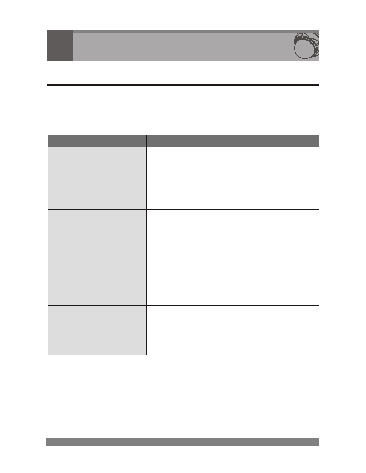
4.1 Troubleshooting
If you experience difficulties operating your camera, refer to the following.
If the guidelines do not enable you to solve the problem, contact an
authorized technician.
PROBLEM
CHECK
Nothing appears on
the screen.
Check all cable connections and the
power of the interface unit.
The image on the
screen is dim.
Is the lens dirty? If so, clean the lens
with a soft, clean cloth.
The camera is not
working properly and
the surface of the
camera case is hot.
Is the camera connected to the proper
power?
The contrast on the
screen is too weak.
Adjust the contrast feature of the
monitor.
Is the camera exposed to strong light?
If so, change the camera position.
The image on the
screen is flickers.
Does the camera face directly into the
sun or fluorescent lighting? If so,
reposition camera. Check for flickerless
setting of the camera.
Page 42

36
4.2 Preventive Maintenance
Following the preventive maintenance schedule allows detection and
correction of minor faults before they become serious and cause
equipment failure.
Periodically perform the following:
1. Inspect all connecting cables for deterioration or other damage.
2. Wipe housing with a clean damp cloth.
Clean P.C. dome/windows with an approved P.C. cleaner.*
3. Verify that all the mounting hardware is secure.
* (plastic polish cleaner)
Page 43
37
5
S
pecificati
on
s
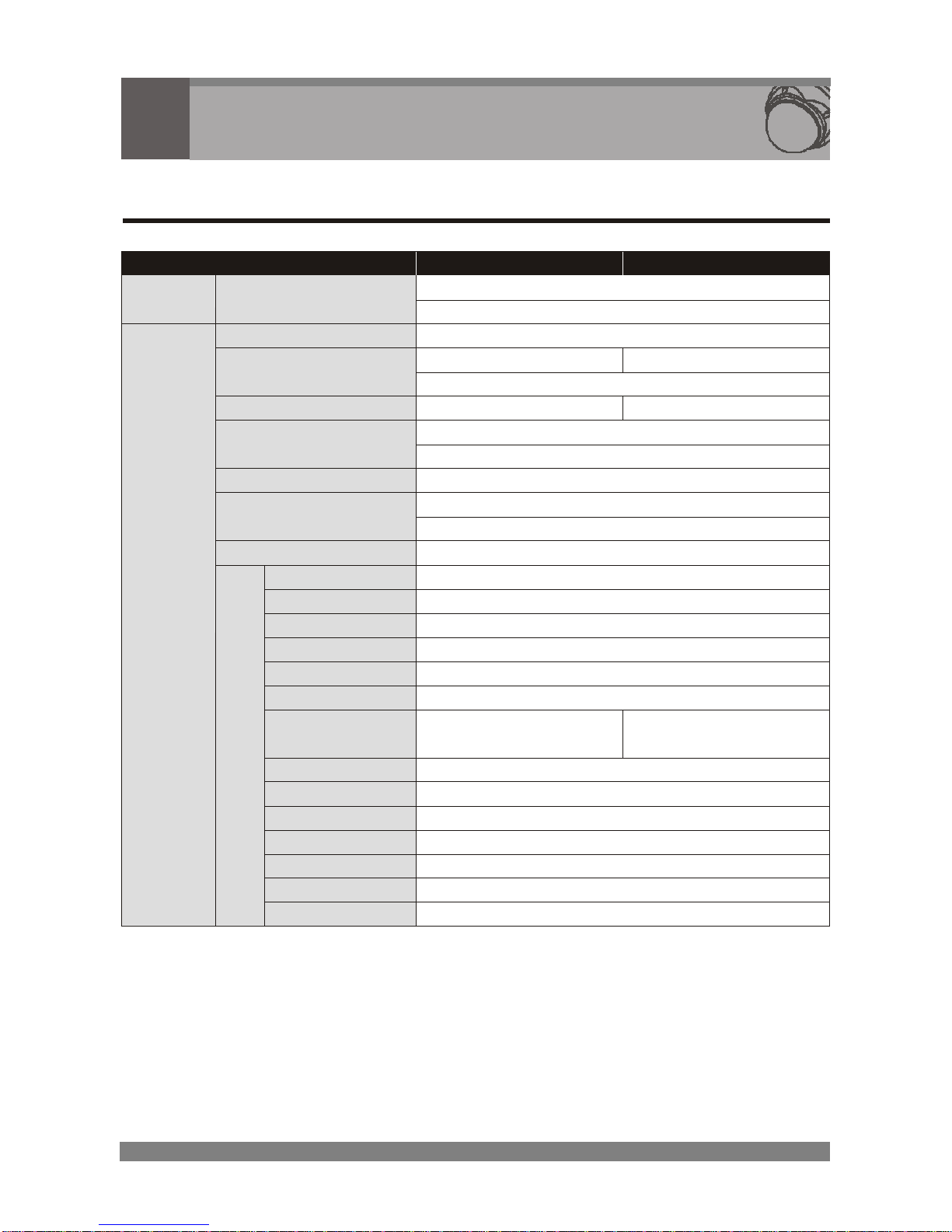
5.1 General Specifications
MODEL
NTSC
PAL
Power
Source
DC12V / AC24V ±10%
POWER
Power Consumption
12.0 Watts
Image Sensor
1/4" SONY Super HAD CCD
Total Pixels
811(H) x 508(V)
795(H) × 596(V)
Scanning System
2:1 interlace
Scanning Frequency
15.734KHz(H), 59.94Hz(V)
15.625KHz(H), 50Hz(V)
Sync. System
Internal / Line Lock
Resolution
480 TV lines(COLOR), 530 TV lines(B/W)
Min. illumination
0.5 lux (Color), 0.05 lux (B/W), 0.001 lux (Low-shutter)
ideo Output
1.0 Vp-p (75 ohm, composite)
S/N Ratio
more than 50dB (AGC off)
Camera Control
RS485 (FastraxII, Pelco-D, Pelco-P)
Focus Mode
Auto / Manual
Distance
0.1M / 1.0M / 1.5M / 2.5M / 6.0M
Digital Zoom
Off / On
White Balance
AWB / Indoor / Outdoor / Manual / WAWB
Auto Exposure
Auto / Shutter PRI / Iris PRI / Manual / Flickerless
Shot
Normal / DIS / WDR / Low Shutter
Shutter Speed
1/60 ~ 1/10,000 sec.
[x2 ~ x60 (Low Shutter)]
1/50 ~ 1/10,000 sec.
[x2 ~ x60 (Low Shutter)]
Iris Control
Auto / Manual (F1.6 ~ F32, Close)
Gain Control
Auto / Manual (0 ~ 30dB)
BLC
Off / On
Brightness
0 ~ 90 steps
Sharpness
0 ~ 15 steps
Picture
Mirror, Freeze, Nega/Posi, DNR, PIP
GENERAL
F
U
C
N
T
I
O
N
C
A
M
E
R
A
D&N Control
Auto / BW / COLOR / GLOBAL [Mechanical IR cut filter]
Page 44
38
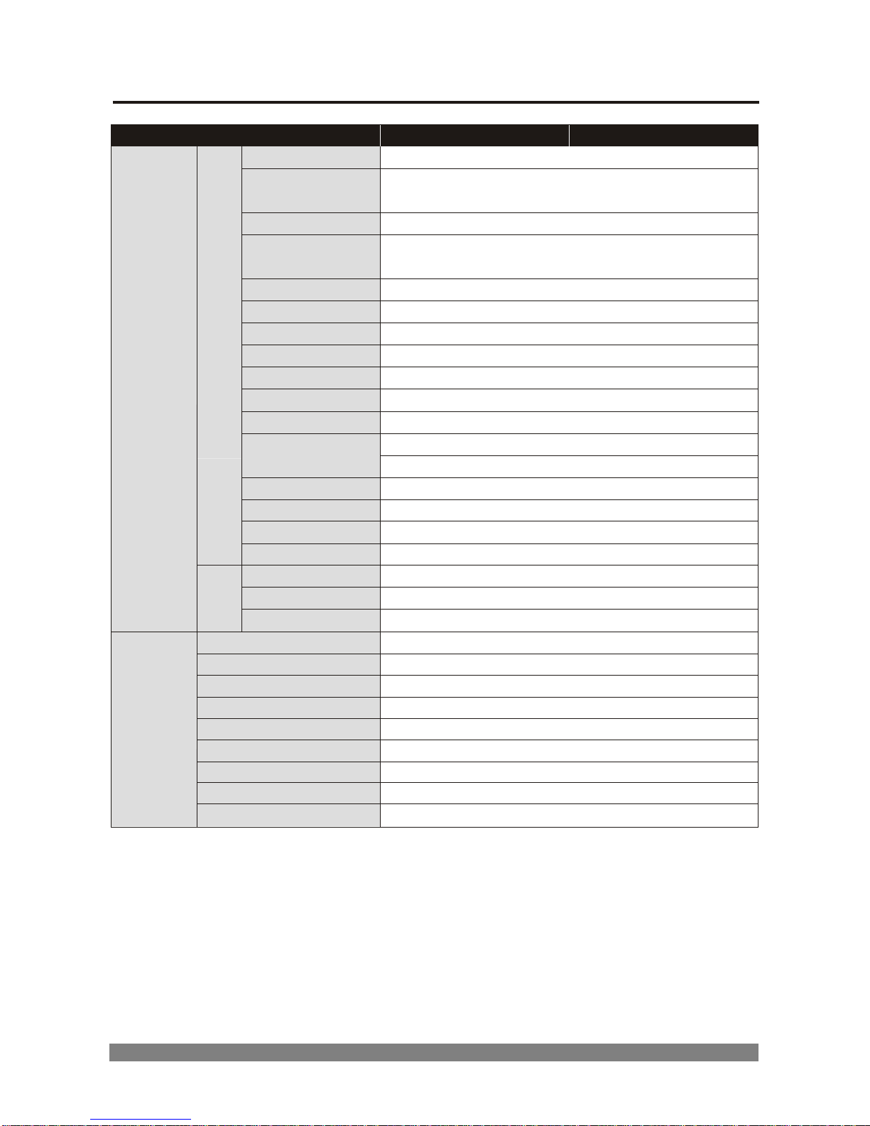
5.1 General Specifications, continued
MODEL
NTSC
PAL
Panning
Angle
360°continuous rotation
Panning Speed
Manual : Max. 150°/sec.
Auto : Max. 375°/sec.
Tilting Angle
0°~ 90° [Auto Flip : Off / On]
Tilting Speed
Manual : Max. 150°/sec.
Auto : Max. 375°/sec.
Preset
60 Positions
Tour
Courses (1~4 x 16 Preset)
Auto Scan
Courses (4)
Area Title
Courses (8)
Alarm Input
Off / NC / NO (1 Channel)
Alarm Output
Off / NC / NO (1 Channel)
Alarm State
Time out / Momentary
485-Termination
Off / On
Auto Calibration
Execution
Password Protection
Off / On (OSD setup protection)
Home Function
Off / On (Preset, Tour, Auto Scan)
Dome ID
63 ID (DIP switch)
F
U
C
N
T
I
O
N
D
O
M
E
Baud Rate
2400 / 4800 / 9600 / 19200 bps (DIP switch)
Zoom Ratio
Optical x22, Digital x11 Zoom (Video AF)
Focus Length
f = 3.9 mm ~ 85.8 mm
GENERAL
L
E
N
S
Aperture Ratio
F1.6 (wide) ~ F3.7 (tele)
Power Input
3-pin terminal block
Video Output
BNC connector
RS485 Control
2-pin terminal block
Alarm Input/Output
4-pin terminal block
Operating Temperature
-10 C ~ +50 C
Operating Humidity
0 ~ 96% (non-condencing)
Storage Temperature
-20 C ~ +60 C
External Dimension
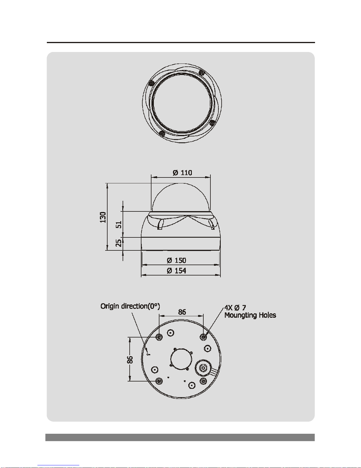
Ø154.0 x 130 (H) mm (Bubble diameter Ø110.0)
CONNECTOR
&
ETC.
Weight
1300g
Page 45
39
5.2 Dimensions
TOP VIEW
SIDE VIEW
BOTTOM VIEW
Page 46
40
APPENDIX. PELCO PROTOCOL FUNCTION LIST
FUNCTION
KEY
Preset No.
How To.
EXAMPLE
PRESET
PRESET
1 - 60
No.+PRESET
1+PRESET
PRESET shortcut saving NOTE1
1- 60
NOTE1
NOTE1
RUN PAN ZERO
PRESET
34
No.+PRESET
34+PRESET
SCAN
PRESET
61 - 64
No.+PRESET
61+PRESET
SCAN LEFT LIMIT
NOTE1
65
NOTE1
NOTE1
SCAN RIGHT LIMIT
NOTE1
66
NOTE1
NOTE1
TOUR
PRESET
71 - 74
No.+PRESET
71+PRESET
ALARM RESET
PRESET
90
No.+PRESET
90+PRESET
RUN HOME
PRESET
91
No.+PRESET
91+PRESET
DOME MENU
PRESET
95
No.+PRESET
95+PRESET
ESC KEY
PRESET
96
No.+PRESET
96+PRESET
CTRL_KEY(In Menu)
PRESET
95
No.+PRESET
95+PRESET
VERSION DISPLAY
PRESET
99
No.+PRESET
99+PRESET
NOTE1
To program, position camera, enter desired preset number(1-60), and hold
down PRESET for two seconds.
In Cm6700 and Cm6800 modes, a label appears on the monitor. Select
‘SET’ and press ACK or tap the joystick to the right and release.
Page 47

Page 48

Via Don Arrigoni, 5 24020 Rovetta S. Lorenzo (Bergamo)
http://www.comelit.it – E mail: [email protected]
50302171A
 Loading...