

Page 1
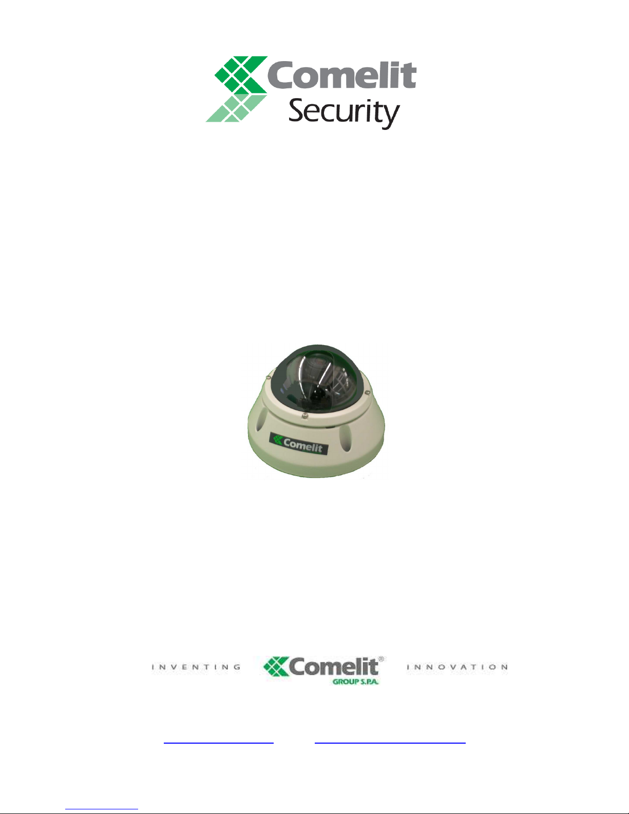
1/3” CCD OUTDOOR VANDALPROOF DOME HOUSING
DAY & NIGHT CAMERA, 12 V DC
ART. 40646
Please read this manual thoroughly before use
and keep it for future reference.
Via Don Arrigoni, 5 24020 Rovetta S. Lorenzo (Bergamo)
Page 2
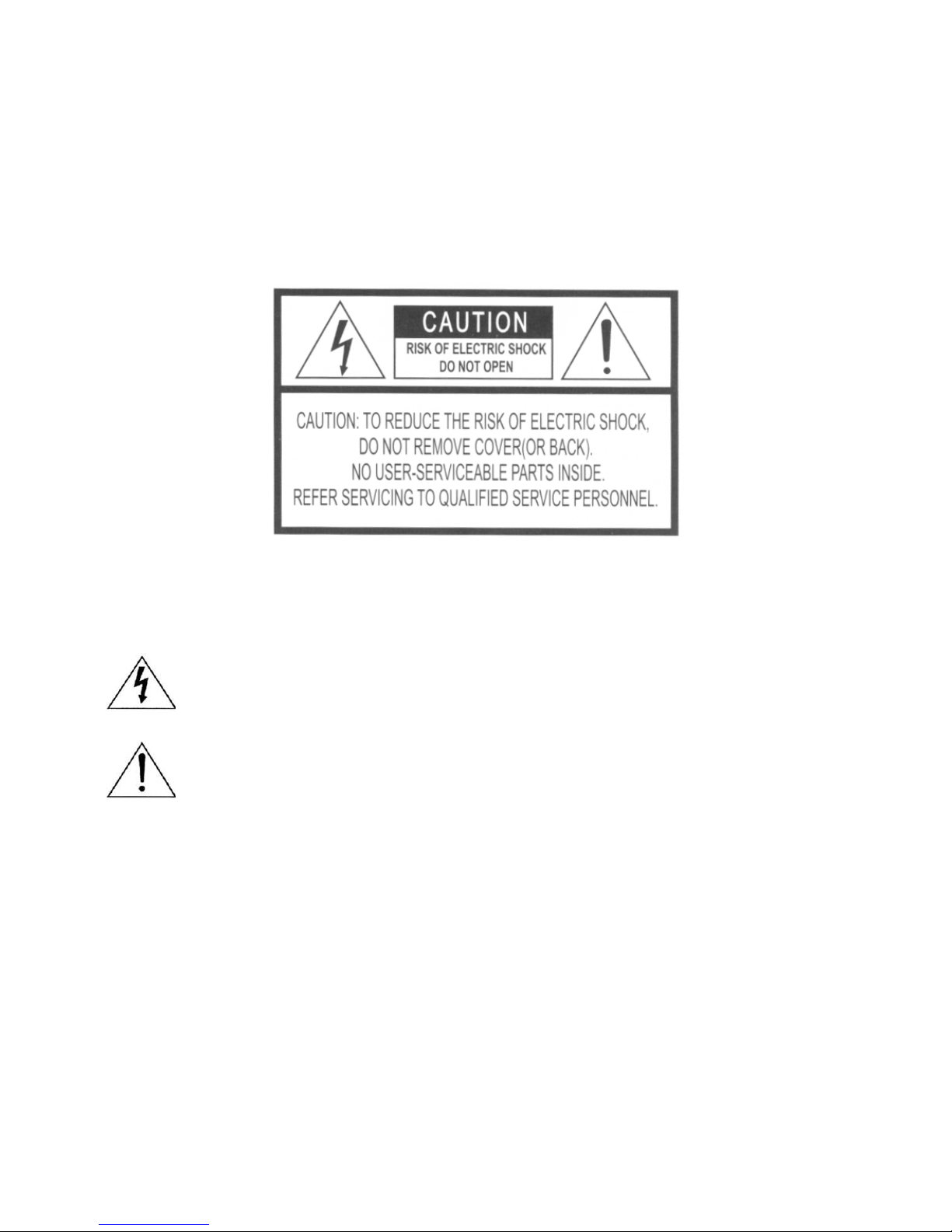
WARNINGS AND CAUTIONS
TO REDUCE THE RISK OF FIRE OR ELECTRIC SHOCK, DO NOT EXPOSE THIS PRODUCT TO RAIN
OR MOISTURE. DO NOT INSERT ANY METALLIC OBJECT THROUGH THE VENTILATION GRILLS OR
OTHER OPENINGS ON THE EQUIPMENT.
CAUTION:
Explanation of graphical symbols
The lightning flash with arrowhead symbol, within an equilateral triangle, is intended to
alert the user to the presence of uninsulated “dangerous voltage” within the product’s
enclosure that may be of sufficient magnitude to constitute a risk of electric shock to
person.
The exclamation point within an equilateral triangle is intended to alert the user to the
presence of important operating and maintenance (servicing) instructions in the literature
accompanying the product.
The user is obliged to inform himself and to conform himself to the national and local
rules concerning the monitoring and the audio and video recording. Nobody else will
consequently be held responsible for an improper use of this system which could break
the laws in force.
Page 3
1
FCC COMPLIANCE STATEMENT.
FCC INFORMATIONS:
THIS EQUIPMENT HAS BEEN TESTED AND
FOUND TO COMPLY WITH THE LIMITS FOR CLASS A DIGITAL DEVICE,
PURSUANT TO PART 15 OF THE FCC RULES. THESE LIMITS ARE
DESIGNED TO PROVIDE REASONABLE PROTECTION AGAINST
HARMFUL INTERFERENCE IN A RESIDENTIAL INSTALLATION. THIS
EQUIPMENT GENERATES, USE AND CAN RADIATE RADIO FREQUENCY
ENERGY AND, IF NOT ISTALLED AND USED IN ACCORDANCE WITH
THE INSTRUCTIONS, MAY CAUSE HARMFUL INTERFERENCE TO RADIO
COMMUNICATIONS. HOWEVER, THERE IS NO GUARANTEE THAT
INTERFERENCE WILL NOT OCCUR IN A PARTICULAR INSTALLATION. IF
THIS EQUIPMENT DOES CAUSE HARMFUL INTERFERENCE TO RADIO
OR TELEVISION RECEPTION, THE USER IS ENCOURAGED TO
CORRECT THE INTERFERENCE TO OWN EXPENSES.
CAUTION:
CHANGES OR MODIFICATIONS NOT EXPRESSLY
APPROVED BY THE PARTY RESPONSIBLE FOR COMPLIANCE COULD
VOID THE USER’S AUTHORITY TO OPERATE THE EQUIPMENT.
THIS CLASS A DIGITAL APPARATUS COMPLIES WITH CANADIAN
ICES-003.
CET APPAREIL NUMÉRIQUE DE LA CLASSE A EST CONFORME À LA
NORME NMB-003 DU CANADA.
CE COMPLIANCE STATEMENT.
WARNING:
THIS IS A CLASS A DIGITAL DEVICE. IN A DOMESTIC ENVIRONMENT
THIS PRODUCT MAY CAUSE RADIO INTERFERENCE, IN WHICH CASE
THE USER MAY BE REQUIRED TO TAKE ADEQUATE MEASURES.
Page 4

1. READ AND KEEP THESE INSTRUCTIONS
Please read this manual thoroughly before use and keep it for future reference.
2. CLEANING
Unplug this equipment from the wall outlet before cleaning it. Use a mild household detergent, never use strong
solvent. Clean the unit with a slightly damp soft cloth.
3. ATTACHMENTS
Never add any attachments and/or equipment without the approval of the manufacturer as such additions may
result in the risk of fire, electric shock or other personal injury.
4. WATER AND/OR MOISTURE
Do not use this equipment near water or in contact with water.
5. ACCESSORIES
Do not place this equipment on an instable cart, stand or table. The equipment may fall, causing serious injury
to a child or adult, and serious damage to the equipment. Wall or shelf mounting should follow the
manufacturer’s instructions and shoul use a mounting kit approved by the manufacturer. This equipment and
cart combination should be moved with care. Quick stops, excessive force and uneven surfaces may cause the
equipment and cart combination to overturn.
6. VENTILATION
If existing, the openings or ventilation grills of the device have been planned with the scope to supply ventilation
to the apparatus, to assure a reliable operation of the same and to protect it from overheating. Do not block or
cover these openings.
7. POWER SOURCES
This equipment should be operate only from the type of power source indicated on the marking label. If you are
not sure of the type of power, please consult your equipment dealer or local power company. Warning if this
equipment works with battery, risk of explosion if battery is replaced by an incorrect type. Dispose of used
batteries according to the local law.
8. GROUNDING OR POLARIZATION
Do not defeat the safety purpose of the polarized or grounding-type plug. A polarized plug has two blades with
one wider that the other. A grounding type plug has two blades and a third grounding prong. The wider blade or
the third prong are provided for your safety. If the provided plug does not fit into your outlet, consult an
electrician for replacement of the obsolete outlet.
9. POWER AND CONNECTION CABLES PROTECTION
Protect the cables from being walked on or pinched particularly at plugs and the point where thy exit from the
equipment.
10. LIGHTNING STORM
For added protection for this equipment during a lightning storm or when it is left unattended and unused for
long periods of time, unplug it from the wall outlet and disconnect the antenna or cable system. This will
prevent damage to the equipment due to lightning and power line surges.
11. OVERLOADING
Do not overload wall outlets and extension cords as this can result in the risk of fire or electric shock.
12. SERVICING
Do not attempt to repair this equipment yourself. The opening and the movement of the covers could you
expose at high voltage or other dangers. Refer all servicing to qualified service personnel.
13. DAMAGE REQUIRING SERVICE
Unplug this equipment from the wall outlet and refer servicing to qualified personnel under the following
conditions:
a. If the power supply cord or the plug has been damaged.
b. If liquid is spilled or objects have fallen into the equipment.
c. If the equipment has been exposed to rain or water.
d. If the equipment does not operate normally by following the operating instructions. Adjust only those
controls that are covered by operating instructions. An improper adjustment of other controls may result in
damage.
e. If the equipment has been dropped or the case damaged.
f. If the equipment exhibits a distinct change in performance.
Page 5

3
14. REPLACEMENT PARTS
When replacement parts are required, be sure the service technician has used replacement parts specified by
the manufacturer or that have the same characteristics as the original part. Unauthorized substitutions may
results in fire, electric shock or other hazards.
15. SAFETY CHECK
Upon completation of any service or repairs to this equipment, ask the service technician to perform safety
checks to determine that the equipment is in proper operating condition.
16. INSTALLATION IN PUBLIC PLACES
This kind of installation would have to be made by specialized personnel and to be in compliance with the local
laws.
Page 6

TABLE OF CONTENTS
INTRODUCTION 5
CAMERA CONNECTIONS 6
BASIC CAMERA INSTALLATION 7
INSTALLING & ADJUSTING CAMERA MODULE 8
BASE INSTALLATION 9
STRUCTURE OF THE SETUP MENU 10
OPERATING CAMERA 12
LENS ADJUSTMENT 22
DC AUTO IRIS LENS 22
TROUBLESHOOTING AND MAINTENANCE 23
SPECIFICATIONS 24
EXTERNAL DIMENSIONS 25
Page 7

5
INTRODUCTION
The camera provides high-quality images using SONY CCD tecnology especially
designed for closed-circuit (CCTV) and security surveillance applications.
Features:
High resolution and high performance 1/3” SONY Super HAD CCD
Technology
Excellent picture quality
540 lines (color) of resolution
0.5 lux (color) and 0.01 lux (B/W) @ F.1.2 Sensitivity
Auto electronic shutter [1/60(1/50) ~ 1/120,000] and manual electronic
shutter modes
OSD (On Screen Display)
DNR (Digital Noise Reduction) auto function
Auto and manual white balance modes
BLC (Back Light Compensation)
Day&Night (Auto / DAY / NIGHT / EXT)
Privacy zone 4 points
AGC (Auto Gain Control)
Sense-up (x2 ~ x32)
MIRROR (Normal /Mirror /Vertical /Rotate)
Video out (BNC)
Motion Detection
Internal / AC line lock
4-9mm Day/Night A/I varifocal lens F1.6~2.4
Operates in 12V DC or 24V AC
Use certified / listed Class 2 power supply only
Camera mount: directly to the wall or ceiling
Test monitor output
Page 8
6
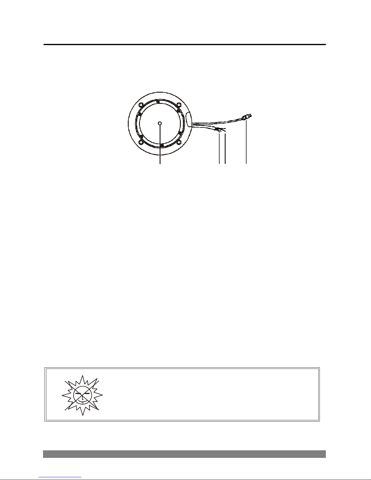
CAMERA CONNECTIONS
1
2 3 4
1. Lens : 4-9mm D&N A/I varifocal lens for wide area monitoring
2. Power : 12V DC / 24V AC +/-10% 50/60Hz +/-1Hz input (red wire +, white wire -)
Use certified / listed class 2 power supply transformer only.
*If using 12V DC power adaptor, use a power supply capable of supplying 6W.
3. IR EXT : dry contact for external control function Day / Night (yellow and black
wires)
4. Video : BNC connector used to connect the camera to a monitor, switcher, etc.
REMINDER:
NEVER AIM THE CAMERA DIRECTLY INTO THE SUN!
Page 9
7
BASIC CAMERA INSTALLATION
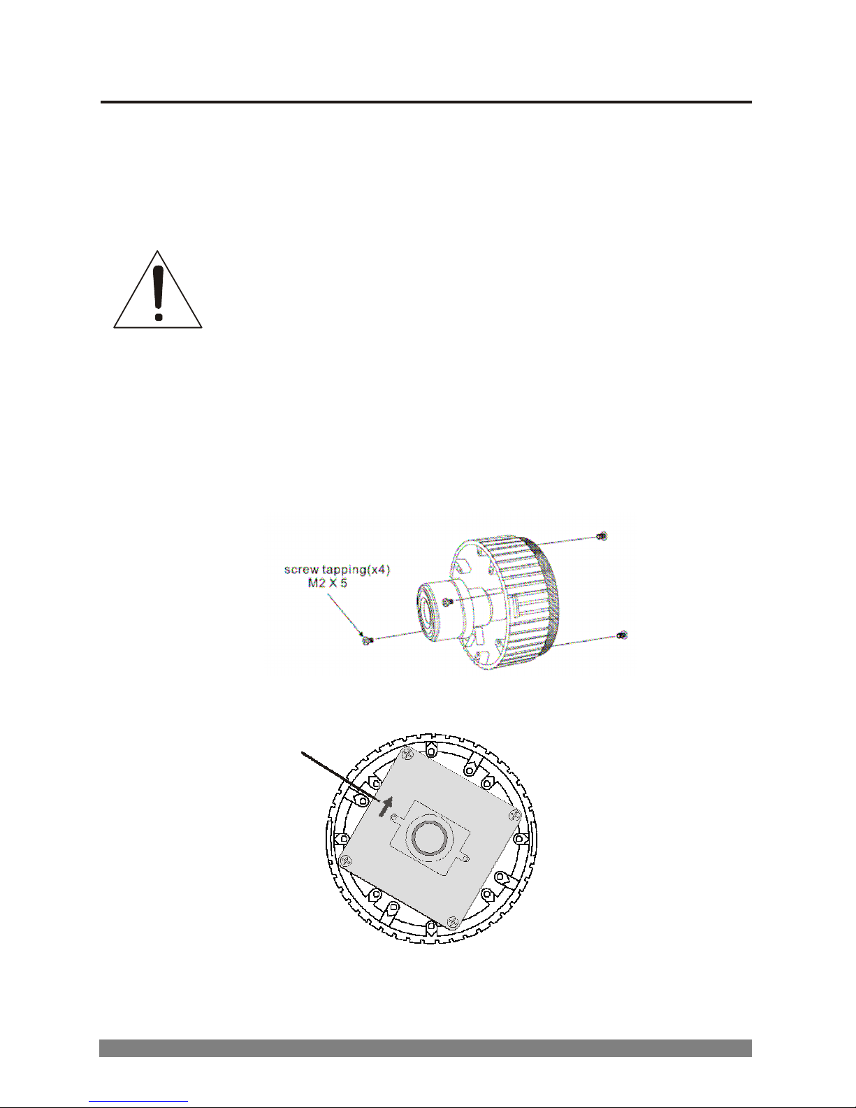
Unpack and identify the followings parts from the product carton:
A. Camera B. Mounting screw
C. Instruction manual (this manual) D. Torx screw driver
Note :
make sure the power is turned off when connecting the power
adaptor cable
.
To mount the board camera on the camera mount bracket, place the 4 board
camera supports on the 4 slot holes near the front and rear of the camera mount
bracket.
TOP
Note: arrow mark indicates the top of the camera image.
Page 10
8
INSTALLING & ADJUSTING CAMERA MODULE
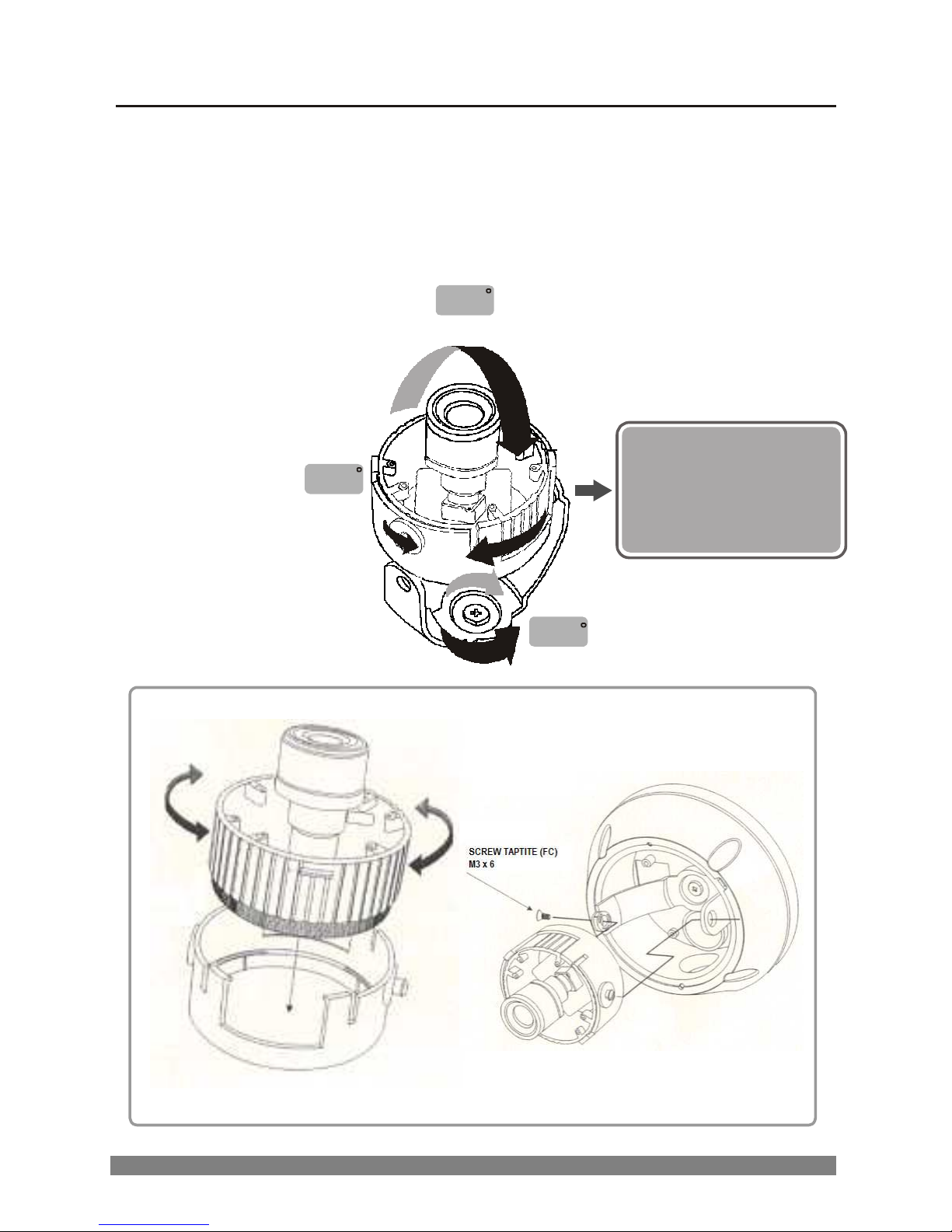
Use the following drawings to install the camera module to the housing.
180
360
3 axis camera construction.
Camera lens can be moved
horizontally or vertically
and freely swiveled to any
angle.
360
Page 11
9
BASE INSTALLATION
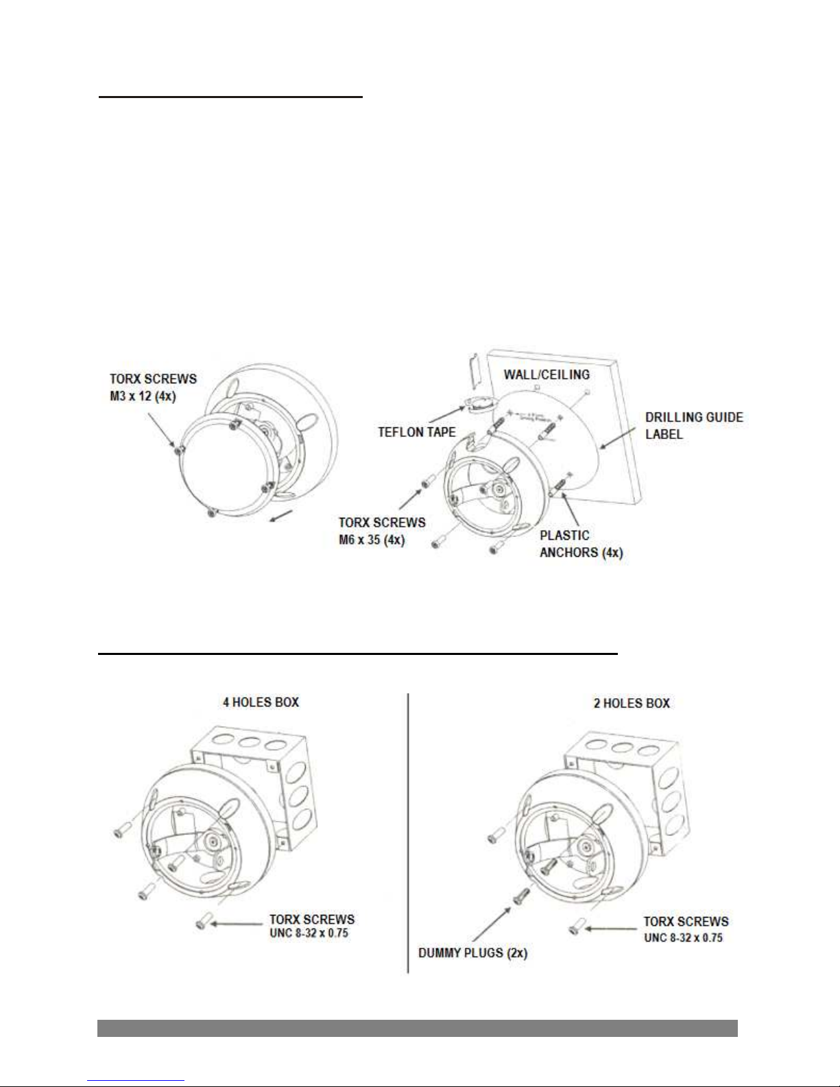
CAUTION: when installing the camera outdoors, the following
instructions must be followed closely
.
1. Loosen the four Torx screws on the housing cover. DO NOT remove the screws
from the cover.
2. Adhere the drilling guide label on the proper location.
3. Drill four holes into the drilling guide label. Insert the screw anchors and attach
the housing using the 4 x M6 Torx screws.
MOUNTING HOUSING TO ELECTRICAL BOX
Page 12
10
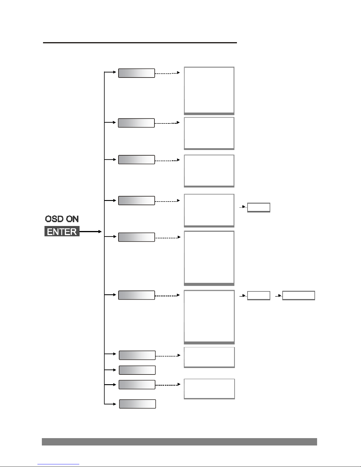
STRUCTURE OF THE SETUP MENU
EXPOSURE
WHITE BAL
DAY/NIGHT
-LENS
-BRIGHTNESS
-BACKLIGHT
-SHUTTER
-AGC
-SENSE UP
-WB MODE
-RED CONT
-BLUE CONT
-PUSH AUTO
-D/N MODE
-AUTO LEVEL
-FILTER DLY
-SENSOR IN
MOTION
-DETECT MODE
-DETECT AREA
-SENSITIVITY
-ALARM TIME
AREA
PRIVACY
-AREA
-MASK
-LEVEL
-TOP
-DOWN
-LEFT
-RIGHT
OPTION
DISPLAY
SYNC
INITIAL
EXIT
-TITLE
-NEGA/POSI
-SHARPNESS
-MIRROR
-ZOOM
-PAN/TILT
-PHASE
-TITLE
-MOTION DET
-DEFAULT
-USER
TITLE
POSITION
Page 13

Page 14

12
OPERATIING CAMERA
<SETTINGS>
Settings can be made using the 5 buttons located at the base of the camera:
1) [ENTER] ON or OFF OSD menu
2) [UP] / [DOWM] UP or DOWN of cursor
3) [LEFT] / [RIGHT] SUB MENU ON or Decision
*when OSD menu is OFF and PAN/TILT is ON, operate by [UP], [DOWN], [LEFT] e [RIGHT]
for PTZ. MOTION DETECT become invalid while moving PAN/TILT.
<MAIN MENU>
M E NU
▶
EXPOSURE
WHITE BAL
DAY/NIGHT
MOTION
PRIVACY
OPTION
DISPLAY
SYNC
INITI
AL
EXIT
+…
+…
+…
+…
+…
+…
+…
A U TO
D EF AU LT
1) EXPOSURE, WHITE BAL, DAY/NIGHT, MOTION, PRIVACY, OPTION and
DISPLAY each have a sub menu and are selected using the [UP]/[DOWN]
buttons.
The sub menu are displayed by [LEFT] / [RIGHT].
2) SYNC: AUTO or INT can be selected.
3) When making INITIAL from USER to DEFAULT, all data is initialized.
*
Selecting "Default" in the
INITIAL
menu, will reset to factory default settings
.
*
When changes are made to the menu, "USER" will be displayed in the INITIAL menu.
4) To exit the menu use the [LEFT] / [RIGHT] buttons when EXIT is highlighted.
* To save the settings in the menu, press the [ENTER] button.
Page 15
13
<EXPOSURE>
Press the [LEFT] or [RIGHT] button to access the menu.
EXPOSURE
▶
LENS
D C/E L C
BRIGHTNESS
0~60
BACKLIGHT
ON/O F F
SHUTTER
1/60(1/50)~1/ 1 0 0 0 0
AGC
OFF/ LO W / MI D / H I G H
SENSE UP
OFF/x2 ~x 32
RETURN
1) LENS DC o ELC can be selected.
2) BRIGHTNESS 0 to 60 can be selected.
*
adjust the brightness level by pressing the [LEFT] or [RIGHT]
button.
Level setting is available in DC and ELC mode.
3) BACKLIGHT ON o OFF can be selected.
*
prevents such a back light effect to secure a clear image under all
illumination environments
.
4) SHUTTER 1/60(NTSC) o 1/50(PAL), FLC, 1/250, 1/500,
1/1000,1/2000, 1/4000, 1/10000 can be selected.
* it is NOT possible to select the shutter speeds when set to ELC. It
becomes 1/60 at NTSC or 1/50 at PAL.
5
) AGC
AGC OFF, LOW, MID, HIGH
can be selected
.
*the level of gain increases, the screen gets brighter.
The level of noise also increases.
6) SENSE UP OFF, x2, x4, x8, x16, x32 can be selected.
*
SENSE UP help maintain a bright, clear screen image by
automatically detecting change in the level of light in low level
conditions.
7) RETURN return to MAIN menu.
Page 16
14
<WHITE BAL>
Press the [LEFT] or [RIGHT] button to access the menu.
WHITE BAL
▶
WB MODE
ATW / AWC / MANUAL
RED CONT
0~127
BLUE CONT
0~127
PUSH AUTO
ON/OFF
RETURN
1) WB MODE
- ATW this mode can be used within the colour temperature range
2.300°K ~ 10.500°K
- AWC
- MANUAL
press the [LEFT] or [RIGHT] button in the PUSH AUTO mode
while the camera is directed at a piece of white paper to obtain
the optimum state under current illumination. In the
environment including the light source is changed, you have to
adjust the white balance again.
manual mode. User can change Red and Blue gain manually.
To adjust the gain, press [LEFT] or [RIGHT] button and
use [UP] and [DOWN] button.
2) RED CONT when set to MANUAL, 0 to 127 can be selected.
Another becomes NOT USE.
3) BLUE CONT when set to MANUAL, 0 to 127 can be selected.
Another becomes NOT USE.
4) PUSH AUTO when set to AWC, OFF to PUSH can be selected.
Another becomes NOT USE.
5) RETURN return to MAIN menu.
Page 17
15
<DAY/NIGHT>
Press the [LEFT] or [RIGHT] button to access the menu.
DAY/NIGHT
▶
D/N MODE
AUTO/DAY/NIGHT/EXT
AUTO LEVEL
0~18
FILTER DLY
4~10 SEC
SENSOR I N
NOT USE / NO / NC
RETURN
1) D/N MODE
- AUTO
this camera has a function which automatically changes to
the appropriate mode for daytime or night-time.
The COLOR mode is operated for daytime, it convert to
B/W mode for night-time.
- DAY
- NIGHT
in this mode the camera outputs the video image only in color.
in this mode the camera outputs the video image only in black
and white.
-
EXT
in this mode an external signal changes the camera output
from COLOR mode to B/W mode and back.
2) AUTO LEVEL when set to AUTO, 0 to 18 can be selected.
*it changes by setting AGC.
AGC OFF: not used.
AGC LOW: 0 to 3 can be selected.
AGC MID: 0 to 11 can be selected.
AGC HIGH: 0 to 18 can be selected.
3) FILTER DLY
when set to AUTO, 4 to 10 can be selected.
When AGC is OFF, NOT USED.
* adjust the delay time of filter movement when
changing from on to off or off to on.
4) SENSOR IN when D/N MODE is EXT, NO or NC can be selected.
when D/N MODE is another (AUTO, DAY, NIGHT), NOT USE
is displayed.
5) RETURN return to MAIN menu
Page 18
16
<MOTION>
Press the [LEFT] or [RIGHT] button to access the menu
.
MOTION
▶
DETECT MODE
ON/OFF
DETECT AREA
+
…
SENSITIVITY
0~8
ALARM TIME
1~60 SEC
RETURN
1) DETECT MODE ON e OFF can be selected.
* turning on becomes invalid while displaying OSD and becomes
effective only after setup DETECT AREA.
2) DETECT AREA DETECT AREA is displayed.
3) SENSITIVITY 0 to 8 can be selected.
4) ALARM TIME 1 to 60 can be selected.
5) RETURN return to MAIN menu.
Page 19
17
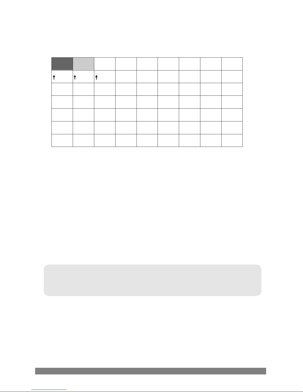
<DETECT AREA>
Press the [LEFT] or [RIGHT] button to access the menu.
cursor
inactive active
- A thick gray shows the cursor.
- When it is transparent, the area becomes active.
* Default is all transparent, it is all active.
- When it is light gray, the area becomes inactive.
- Cursor moved by [LEFT] or [RIGH
]
.
- When [UP] or [ DOWN] is pushed, it becomes active or inactive.
- Press [ENTER] to return to the MOTION menu.
NOTE :
BLC automatically becomes effective on this screen.
Page 20
18
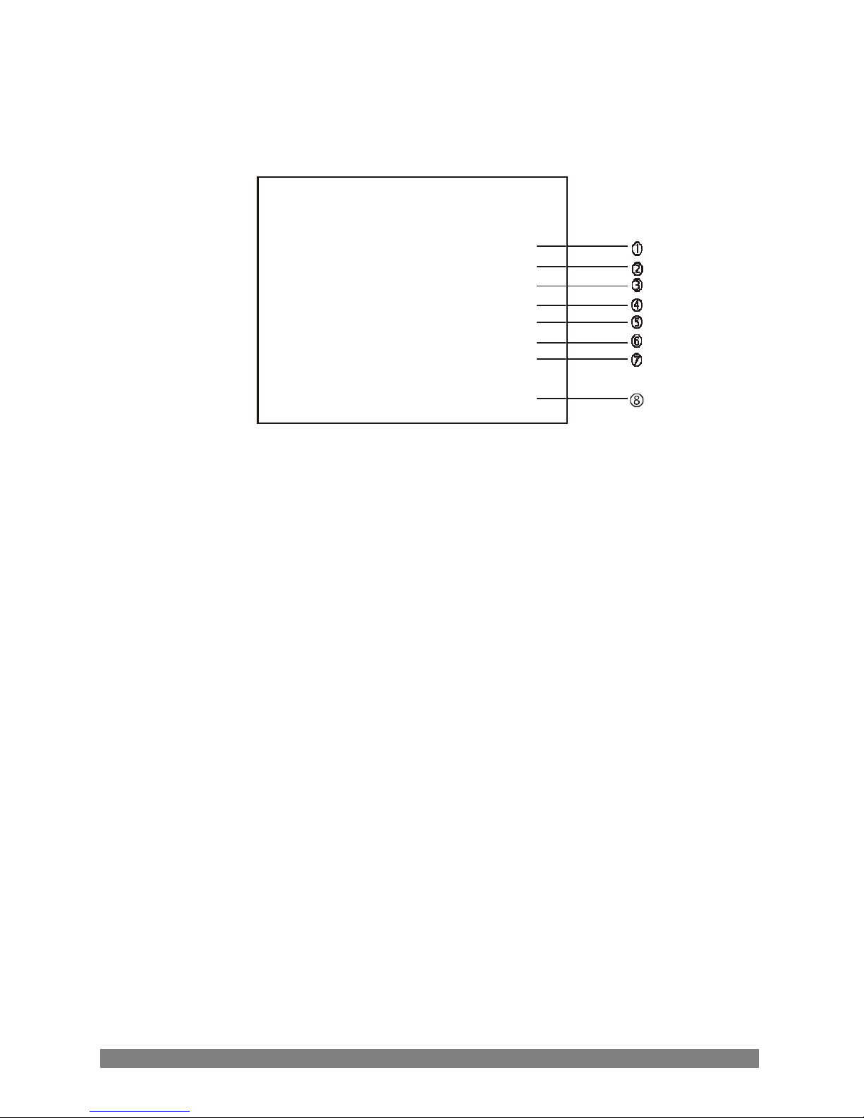
<PRIVACY>
Press the [LEFT] or [RIGHT] button to access the menu
.
PRIVACY
▶
AREA
1~4
MASK
ON/OFF
LEVEL
0~15
TOP
3~124/ 6~150
DOWN
5~126/ 8~152
LEFT
0~187/ 0~185
RIGHT
2~189/ 2~187
RETURN
1) AREA 1 to 4 can be selected.
2) MASK ON or OFF can be selected.
3) LEVEL when MASK is ON, 0 (black) to 15 (white) can be selected.
*it set the same value regardless of a set value of the AREA size.
4) TOP when MASK is ON, 3 to 124 (NTSC) or 6 to 150 (PAL) can
be selected.
5) DOWN when MASK is ON, 5 to 126 (NTSC) or 8 to 152 (PAL) can
be selected.
6) LEFT when MASK is ON, 0 to 187 (NTSC) or 0 to 185 (PAL) can
be selected.
7) RIGHT when MASK is ON, 2 to 189 (NTSC) or 2 to 187 (PAL) can
be selected.
8) RETURN return to MAIN menu.
Page 21
19
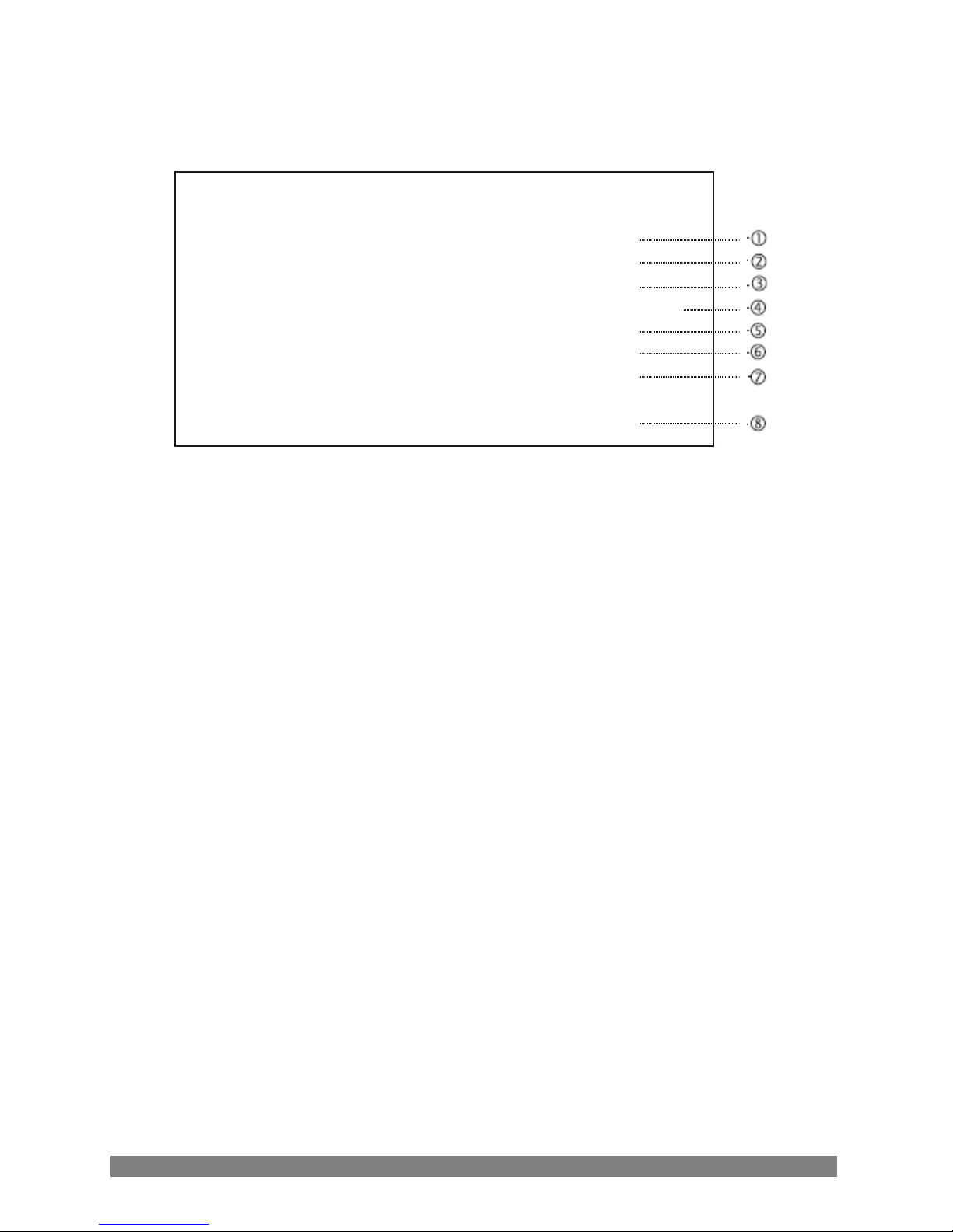
<OPTION>
Press the [LEFT] or [RIGHT] button to access the menu.
TE
OPTION
▶
TITLE
+…
NEGA/POSI
POSI/NEGA
SHARPNESS
0~15
MIRROR
NORMAL/MIRROR/VERTICAL/RO
ZOOM
OFF/ON1~ON8
PAN/TILT
ON/OFF
PHASE
0 ~ 524 / 0 ~ 624
RETURN
1) TITLE TITLE is displayed.
2) NEGA/POSI NEGA or POSI can be selected.
3) SHARPNESS 0 to 15 can be selected.
4) MIRROR NORMAL, MIRROR, VERTICAL, ROTATE can be
selected.
- MIRROR Horizontal image inversion
- VERTICAL Vertical image inversion
- ROTATE Horizontal and vertical image inversion
5) ZOOM OFF (x1) and ON 1 to ON8 (x4) can be selected.
6) PAN/TILT OFF or ON (x2) can be selected.
* when OSD menu is OFF and PAN/TILT is ON, operate
by [UP], [DOWN], [LEFT] e [RIGHT].
7) PHASE sync phase is adjustable in line lock mode (Auto mode) 0 ÷
524 (NTSC) or 0 ÷ 624 (PAL).
8) RETURN return to MAIN menu
NOTE:
- when the power frequency is 50Hz, you cannot use the line-lock for NTSC models.
- when the power frequency is 60Hz, you cannot use the line-lock for PAL models.
Page 22
20
NOTE: ■ = is blank
_ = is space
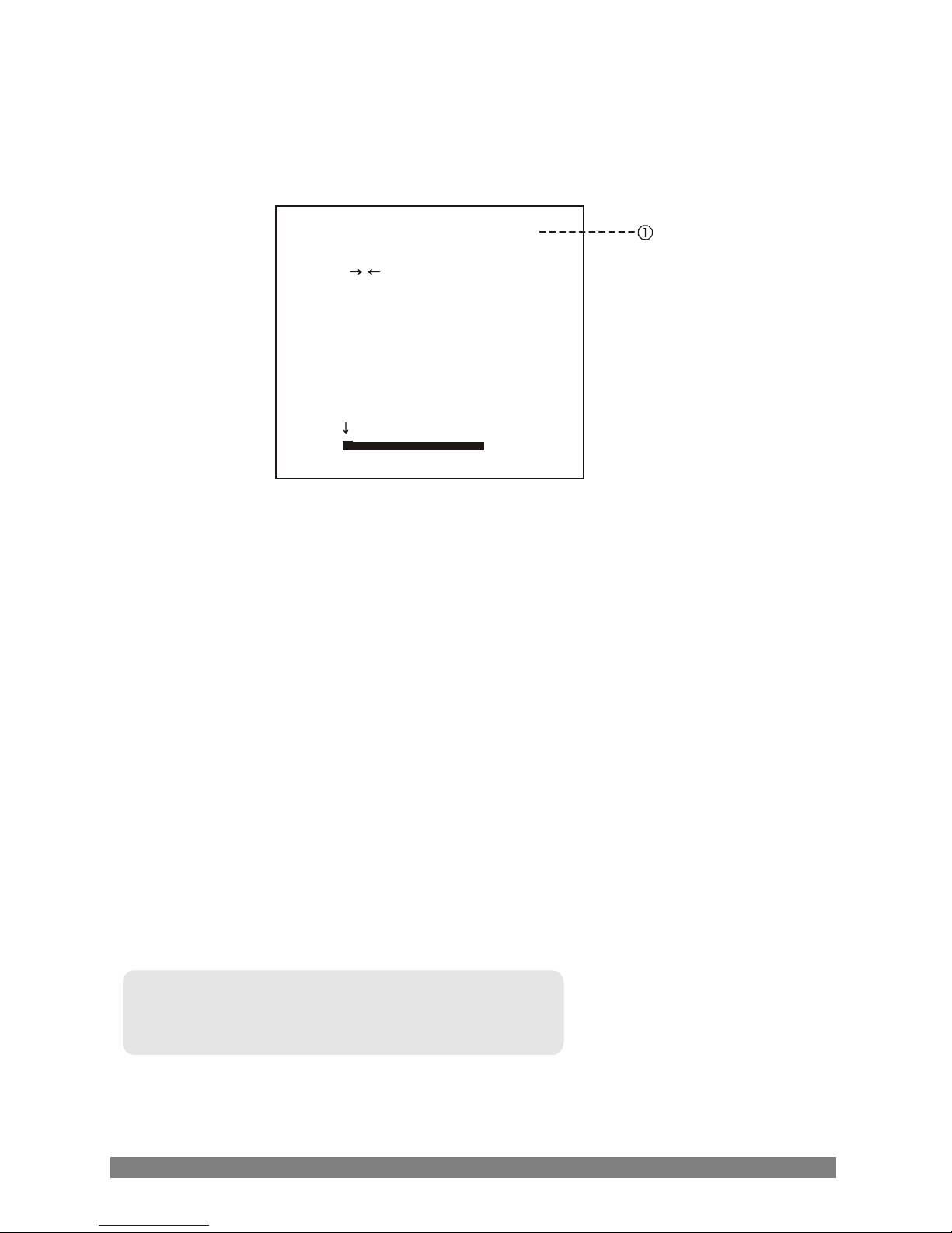
<TITLE>
Press the [LEFT] or [RIGHT] button to access the menu.
TITLE
BS
POS END
ABCDEFGH I J KLM
NOPQRSTU VWXYZ
abcdefghi j k l
m
nopqrs t uvwxyz
012 3 456 78 9 :
; .
* /
+ - ~
! # %& ( ) "
_
1) TITLE it moves by [UP], [DOWN], [LEFT] and [RIGHT].
Characters are set by pressing [ENTER]. The character
from 0 to 9 can also be set.
- ← move to left when [ENTER] button is pushed by ←
- → move to right when [ENTER] button is pushed by →
- BS erase the character
- POS change the position of the title
(if you want to change the position of the title, press [ENTER]
button at the POS. Find the position you wish to display the title
by using 4 directional buttons and press the [ENTER] button.
*
one or more characters have to be set for a position change to occour.
- END when [ENTER] is pushed by END, return to the TITLE menu.
Page 23
21
<DISPLAY>
Press the [LEFT] or [RIGHT] button to access the menu.
DISPLAY
▶
TITLE
ON/OFF
MOTION DET
ON/OFF
RETURN
1) TITLE ON or OFF can be selected.
2) MOTION DET ON or OFF can be selected.
3) RETURN return to MAIN menu.
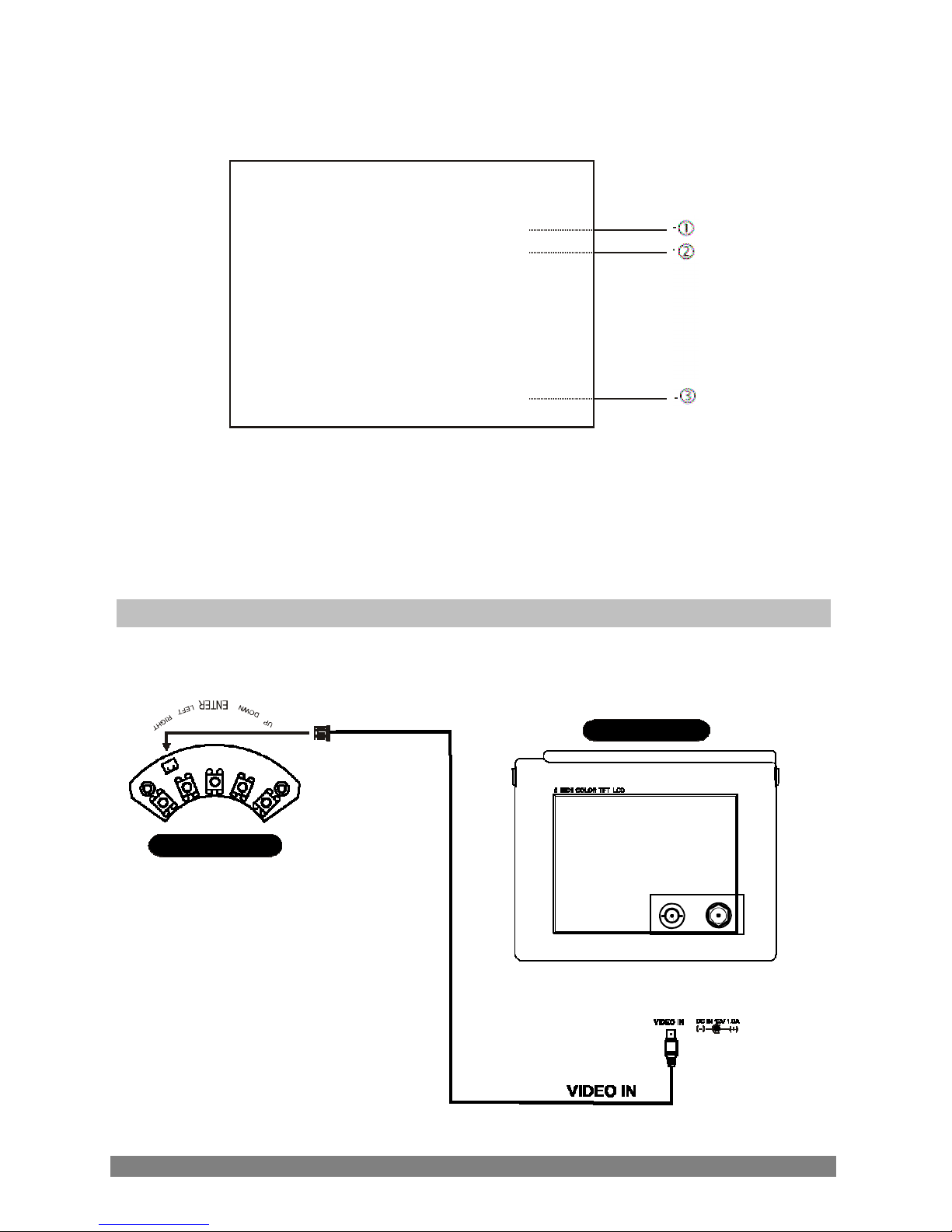
Video out check
Monitor di test
Tastiera
RG59 cable
Video out
Page 24
22
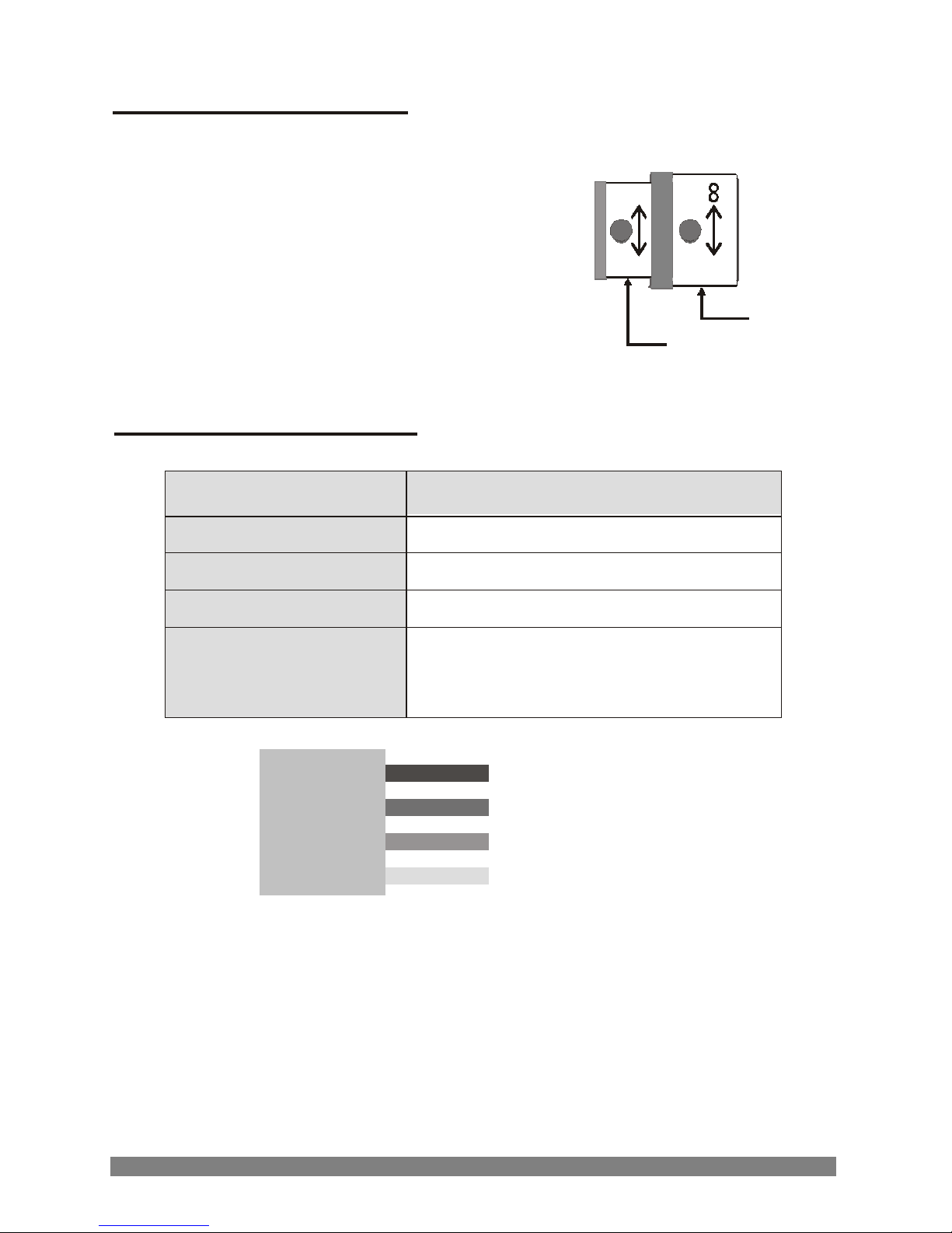
N
LENS ADJUSTMENT
Filed of view: adjust setting from Tele (T)
to Wide (W) field of view.
Focus: adjust lens focus from Near (N)
to infinity (∞).
Focus
Field of view
DC AUTO IRIS LENS
4-9
Image size
1/3" CCD
Focal lenght
4.0 - 9.0 mm 5%
Aperture ratio
1 : 1.6 5%
Angular
Field of view
DIAGONAL
4mm : 92.4
o
9mm : 39.2
o
LENS
White
Control ( + )
Black Control ( - )
Red Drive ( + )
Green
Drive
( - )
Page 25
23
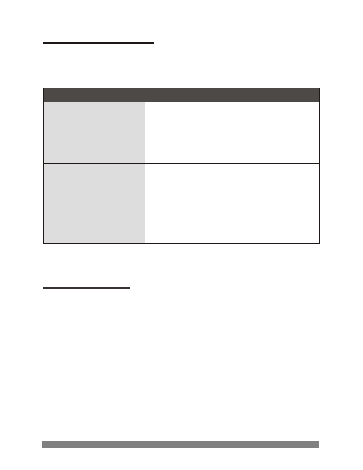
TRUBLESHOOTING
If you experience difficulties operating your camera, refer to the following. If the
guidelines do not enable you to solve the problem, contact an authorized
technician
PROBLEM
CHECK
Nothing appears on
the screen
Is the camera connected with the
monitor?
Is there power to the monitor?
The image on the screen
is dim
Is the lens dirty? If so, clean the lens
with a soft, clean cloth
The contrast on the
screen is too weak
Adjust the contrast feature of the monitor.
Is the camera exposed to strong light?
If so, change the camera position.
The image on the screen
flickers
Does the camera face directly into the sun
or fluorescent lighting?
If so, reposition camera
.
MAINTENANCE
Following the preventive maintenance schedule allow detection and correction of
minor faults before they become serious and cause equipment failure.
Every three moths:
1. Inspect all connecting cables for deterioration or other damage
2. Clean components with a clean damp cloth
3. Verify that all the mounting hardware is secure
Page 26
24
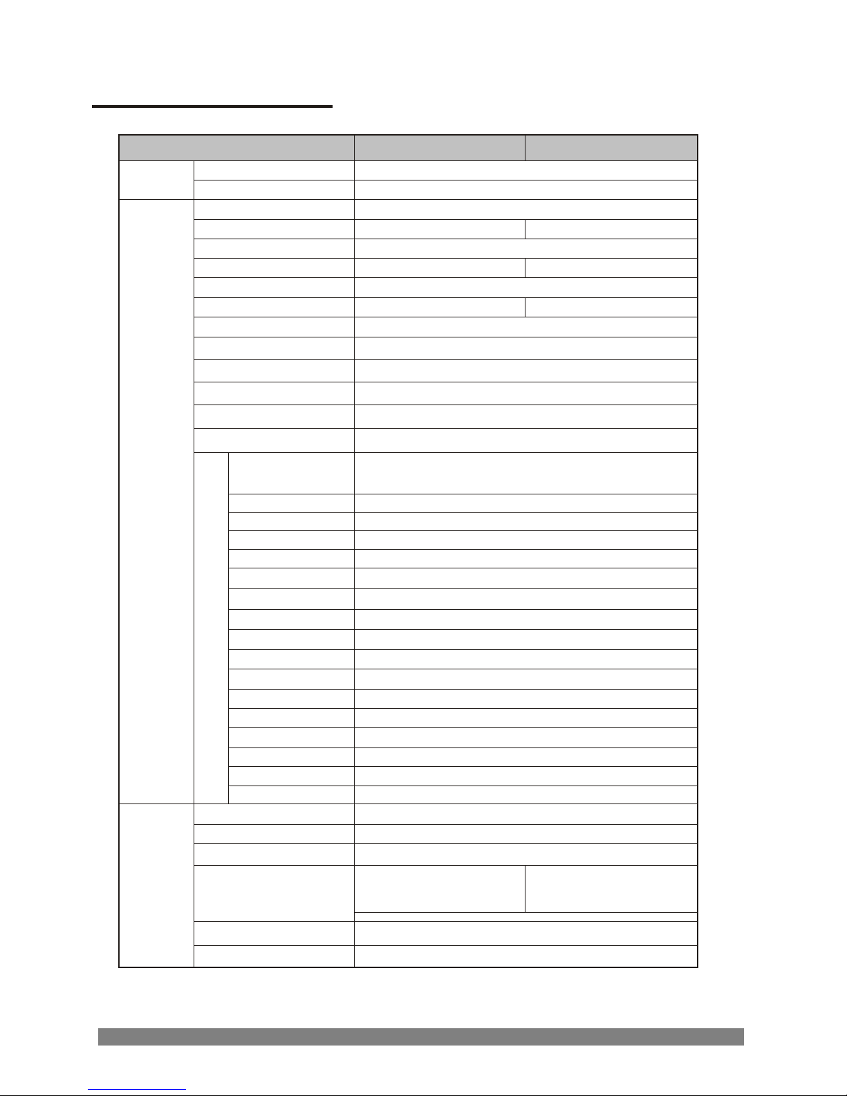
SPECIFICATIONS
MODEL
NTSC
PAL
Power source
12V DC / 24V AC
Power
Power consumption
3.5 W
Image sensor
1/3" SONY Super-HAD CCD
Total number of pixels
811(H) x 508(V)
795(H) x 596(V)
Scanning system
2:1 interlace
Scanning frequency
15,734KHz(H) x 59,94Hz(V) 15,625KHz(H) x 50Hz(V)
Sync. system
Internal / Line lock
Electronic shutter
1/60 ~ 1/120,000 sec.
1/50 ~ 1/100,000 sec.
Resolution
540 TVL (color)
Min. illumination
0.5 lux (color), 0.01 lux (B/W) @ F1.2, 50 IRE
Video output
1.0 Vp-p (75 ohm, composite)
S/N ratio
> 50dB (AGC OFF)
Camera control
Tact switch
DNR function
ON
Auto exposure
1
/60(1/50) / FLICKERLESS / MANUAL SHUTTER
(1/250, 1/500, 1/1000, 1/2000, 1/4000, 1/10000)
Lens
DC / ELC
Brightness
0 ~ 60
BLC
ON / OFF
AGC
OFF / LOW / MIDDLE / HIGH
Sense-up
OFF / x2 /x4 / x8 / x16 / x32
White balance
ATW / AWC / MANUAL
Day & Night
AUTO / DAY / NIGHT / EXT
Motion detection
OFF / ON
Privacy zone
OFF / ON (4)
Display title
OFF / ON
Video picture
POSI / NEGA
Sharpness
0~15
Mirror
NORMAL / MIRROR / VERTICAL / ROTATE
Sync.
INT/AUTO
Zoom
OFF /ON(x8) / PTZ (x2)
General
F
U
N
C
T
I
O
N
Preset
INITIAL / EXIT(auto save) / RETURN
Power input
2 pin wire
Video output
BNC connector
Lens mount
Fixed mount
f=4~9mm F1.6~2.4
Varifocal DC auto iris
f=4~9mm F1.6~2.4
Varifocal DC auto iris ICR
Lens
Operating temperature
from -10oC to +50oC [14oF ~ 122oF]
Connectors
&
etc.
Operating humidity
96%
max
(non-condensing)
Page 27
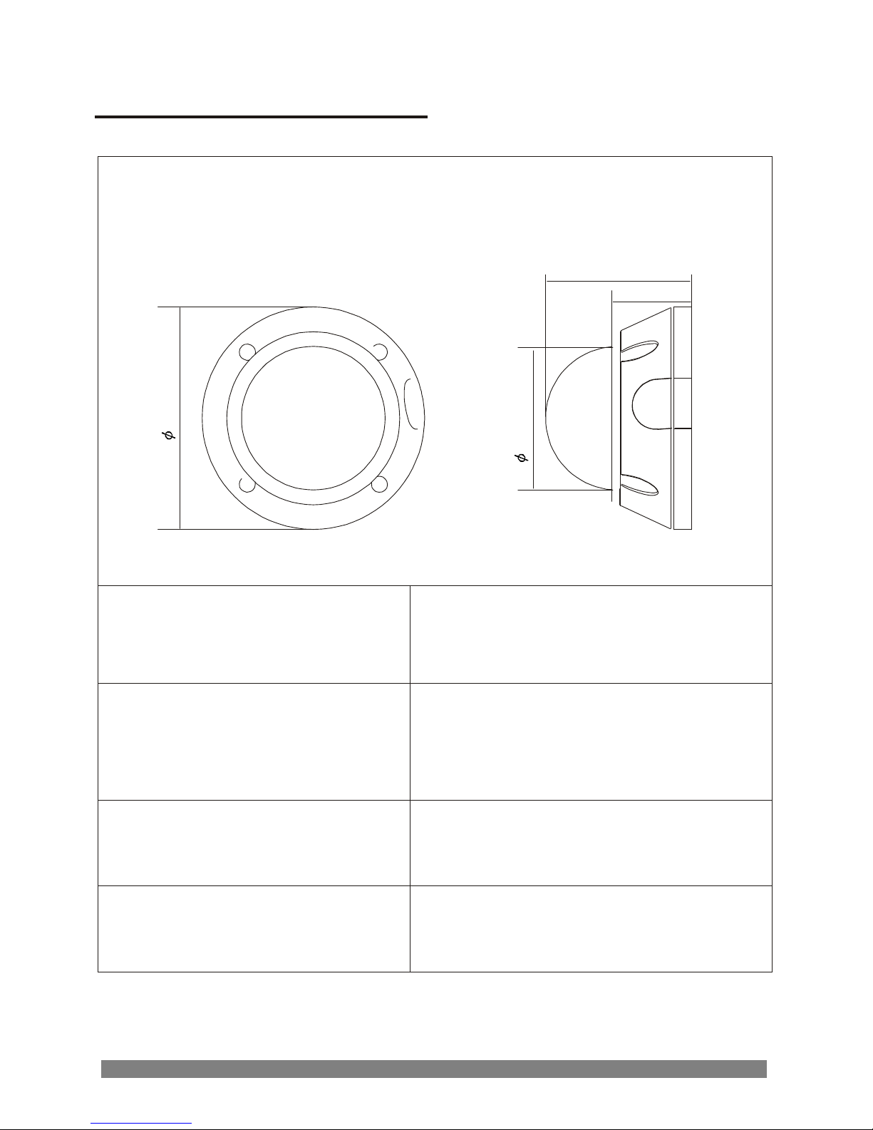
25
144
88
(
I
nner)
EXTERNAL DIMENSIONS
Dimensions
94.5
51.5
Unit: mm
Maximum camera and lens size
2.6 L x 1.65 W x 1.65 H inch
6.5 L x 4.2 W x 4.2 H cm
Window size
0.1 inch; 2.5mm thick
impact resistant P.C (LEXAN)
3.46 inch; 8.8 cm diameter
Cable entry
2 threaded holes 3/4"
Weight - Unit:
Shipping:
1.76 lb; 0.8 kg
1.98 lb; 0.9 kg
Page 28

Via Don Arrigoni, 5 24020 Rovetta S. Lorenzo (Bergamo)
 Loading...