

Page 1
COMECO Inc., P.O.Box 378, Plovdiv 4000, BULGARIA, tel: +359 32 646523, 646524, fax: 634089
e-mail: [email protected], WWW.COMECOGROUP.COM
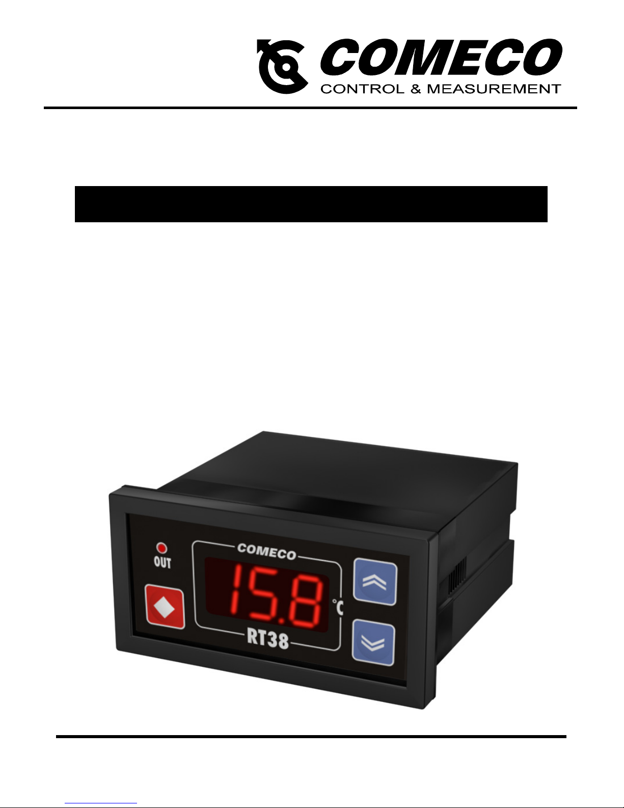
RT38
OPERATION MANUAL
Please read this Operation Manual before mounting and operating!
Save the Manual for future references!
PROGRAMMABLE CONTROLLER
v13-12.12
Page 2

Overview
2
RT38 is an ultra-economical ON/OFF
programmable controller for temperature
and other technological parameters,
available in 2 universal-input versions –
RTD (for 7 selectable Pt and 4 Cu sensor
types) and T/C (for 3 selectable
thermocouples) – as well as in versions
for linear current and voltage signals.
The device is equipped with a 3-digit LED
display and 1 programmable relay
control/alarm output, and can be ordered
in various cases including the smallest
1/32 DIN case or enclosed in a standard
11-pin box for DIN-rail mounting and
for mains or low-voltage supply.
Mounting
Panel mounting ('B' / 'H' / 'V' / 'S' / 'L' / 'M')
♦ Place RT38 into an appropriate panel
cut-out.
♦ Tighten it into place using
the enclosed mounting bracket(s).
DIN-rail mounting ('R')
RT38-R can be easily mounted on every
35 mm rail conforming to EN50022
by the means of a standard UNDECAL
socket base.
Page 3
Wiring
3
Important notes:
♦ Power supply must be turned off
during mounting and wiring!
♦ In case of 90...250 VAC/DC power supply,
grounding the device via separate wire
is mandatory for covering safety standards.
♦ With DC power supply,
the polarity does not matter.
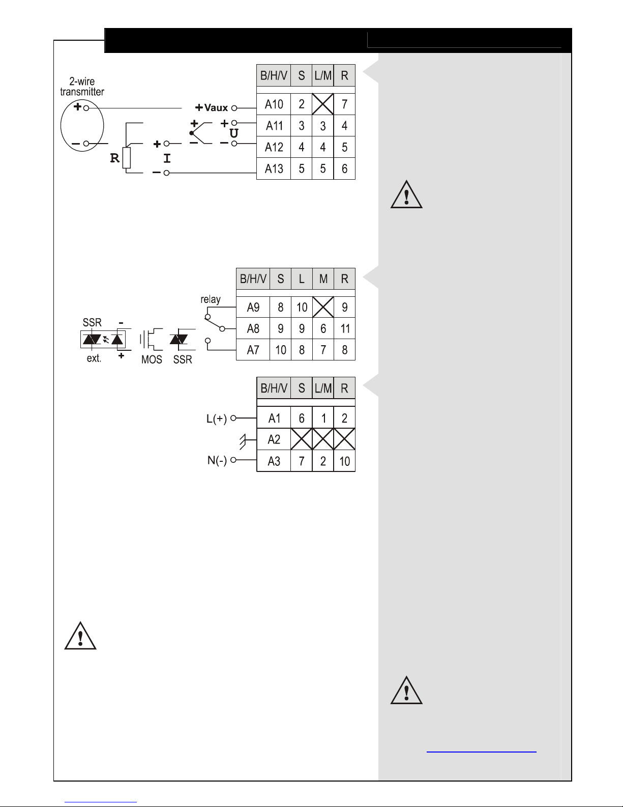
Input signal wiring
Connect the input
with regard to its type
through the respective and
depending on the case type
(see 'Specifications')
terminals on the device back.
Voltage transmitters
should be powered
ONLY
by external source!
Output wiring
Connect the output
with regard to its type
(see 'Specifications')
via the respective terminals.
Power supply wiring
Connect the right power
supply voltage for your device
(see 'Specifications')
through the respective
terminals.
More detailed
wiring schematics
are available at
comecogroup.com
under 'Support' tab.
Page 4

Electro-Magnetic Interference (EMI) Issues
4
Important note:
A built-in RC noise
suppression circuit may
be connected in parallel
with relay contacts.
Full AC voltage isolation
may NOT be provided
when relay contacts
are open.
Small AC current
(≈ 1.5 mA at 230 VAC)
may still flow through
the RC circuit!
♦ All signal wires must be shielded.
They must not be packaged together
with power cables!
♦ Never lay the signal wires close
to inductive or capacitive noise
sources, such as relays, contactors,
motors, etc.!
♦ All shields have to be grounded ONLY
at one end, as closer as possible
to the controller terminals!
♦ Avoid sharing supply lines
with powerful consumers,
especially with inductive loads,
switched on and off.
♦ To stop unwelcome interference
signals entering through the power
supply lines, use shielded 1:1
isolation transformer!
♦ Shunt all switched (not only those
switched by the controller) inductive
consumers with special suppression
networks: RC group and varistor -
for AC loads, or diode - for DC loads.
♦ If the controller operates in a very
powerful EMI area, it has to be
mounted inside a grounded metal
shielding box!
Page 5
Parameter Programming
5
Some parameters
are accessible only
when the respective
functionality is installed.
(see 'Specifications').
- Changing
Point Position value
reflects the real value
of all parameters
with ISU!
E.g.: changing
Point Position value
from (0) to (0.0)
would change
a Set-point value
of 100 to 10.0!!!
Device parameters
RT38 is a programmable device whose
service behavior is determined by a set
of parameters. All the parameters, along
with their names, symbols, and value ranges,
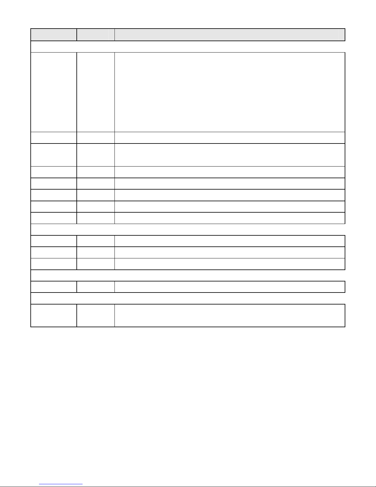
are given in Table 1.
Setting numerical parameter value
♦ Enter parameter value adjustment mode
(see 'Program Levels').
♦ The whole part of the value together with
the left zeroes appears on the display,
and the rightmost digit blinks.
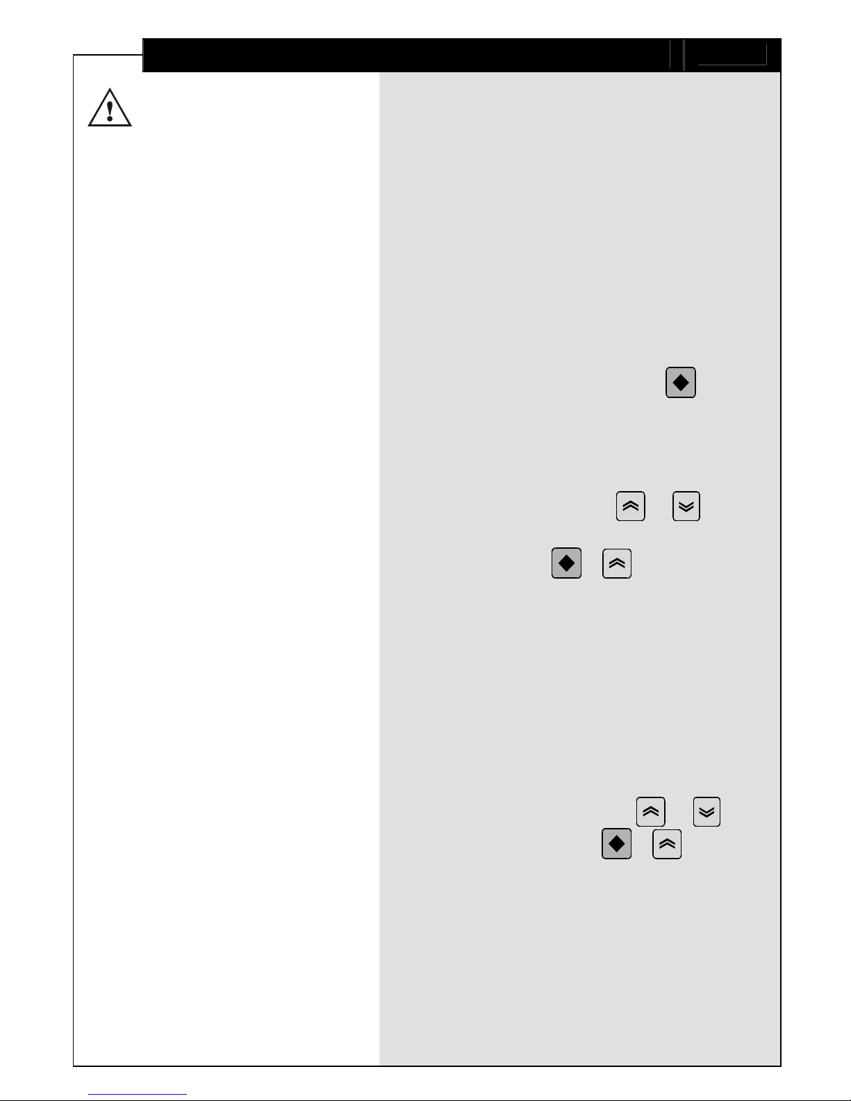
♦ To select another digit, press .
♦ The 2 rightmost digits can accept values
from 0 to 9, and the leftmost digit
can also accept the values - and `.
♦ To increase or decrease the blinking digit
value, use respectively or
.
♦ Confirm the adjusted value by pressing
simultaneously + .
♦ If the new value has not been confirmed
and no key has been pressed for a certain
period of time, value adjustment
automatically ceases, and the parameter
retains its initial value.
Setting symbolic parameter value
♦ Enter parameter value adjustment mode
(see 'Program Levels').
♦ Read the blinking parameter value.
♦ To change the value, use or ,
and to confirm, press + .
♦ If the new value has not been confirmed
and no key has been pressed for a certain
period of time, value adjustment
automatically ceases, and the parameter
retains its initial value.
Page 6
Parameter Symbol Description
Parameters of Configuration level
Input Type
inP
Type of signal that can be connected to the device input
Display Offset
oFS
Constant to be added to the measured input value
Point Position
Pnt
Display decimal point position
Filter Time
\t
Relative time constant of the input filter
Filter Band
\b
Zone around the measured value, within which the filter is active
Unit
Unt
Temperature measurement unit
Input Low
ILo
Display value at low limit of the linear input range
Input High
Ihi
Display value at high limit of the linear input range
Parameters of Parametric level
Hysteresis
HYS
Relay switching differential
Direction
dir
Relay action direction
Hold
HLd
Holds the output reaction
Parameter of Basic (operating) level
Set Point
%P
Control set-point value
Access-Control Parameter (parameter of Hidden level)
Lock Keyboard
Loc
Keyboard locking mode
Page 7
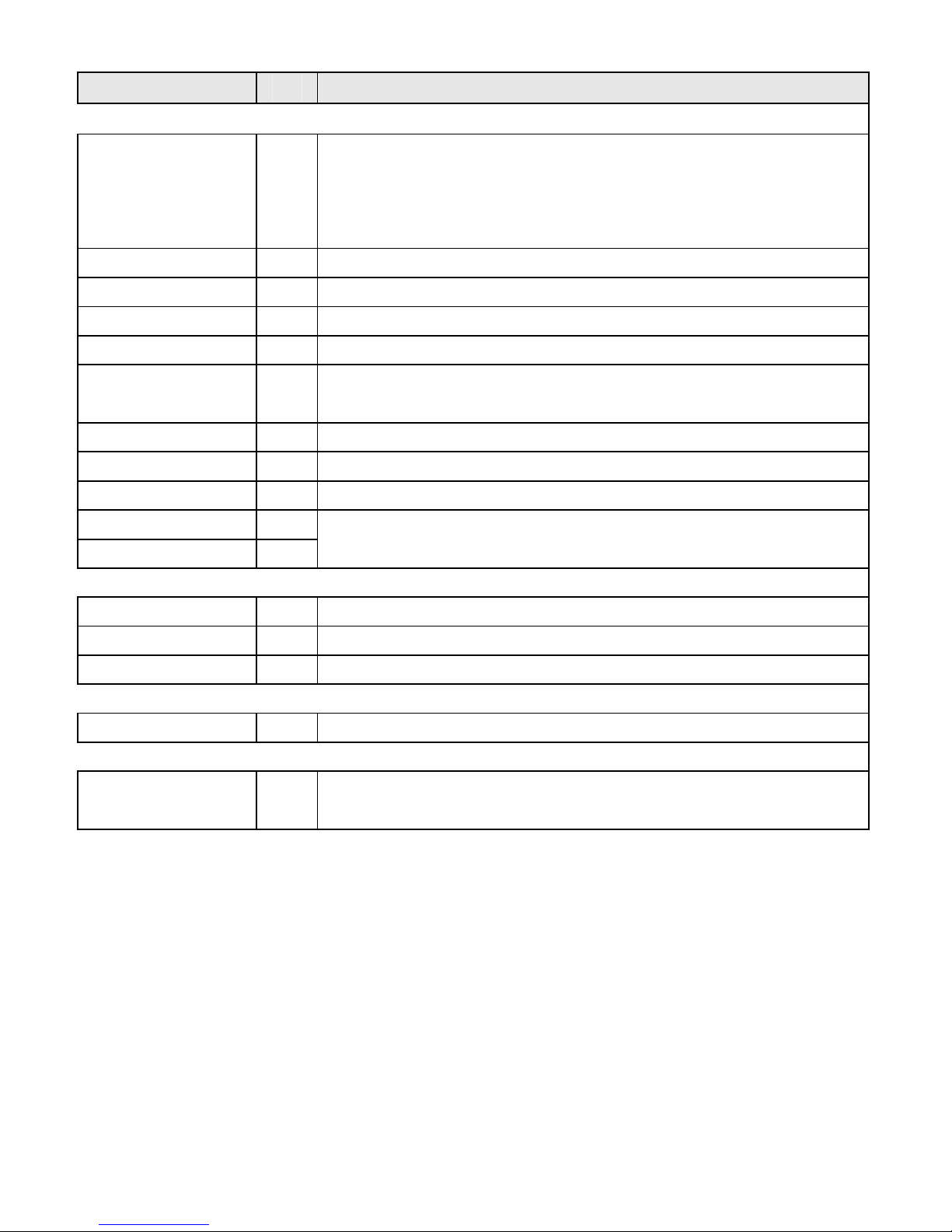
Table 1
Value Unit Notes
RTD -
Py1 (Pt50), Py2 (Pt100), Py3 (Pt500), Py4 (Pt1000),
Py5 (Pt46-GOST), Py6 (Pt50-GOST), Py7 (Pt100-GOST),
Cw1 (Cu50, 1.426), Cw2 (Cu100, 1.426),
Cw3 (Cu50, 1.428), Cw4 (Cu100, 1.428)
T/C - yxJ (T/C "J"), yx" (T/C "K"), yxt (T/C "T")
current - $20 (4…20 mA), )20 (0…20 mA)
voltage - )10 (0…10 V)
-199 ... 999 ISU display offset value
0, 0.0 -
when indicating values with the input-signal measurement unit (ISU);
z (tens not shown), z (tens shown within the -19.9...99.9 range)
0 … 100 -
0 … 100 -
.C, .F -
This parameter makes sense ONLY in case of a temperature sensor!
-199 ... 999 ISU
-199 ... 999 ISU
These parameters make sense ONLY in case of a linear input signal!
Set Input Low < Input High!
0 ... 100 ISU
0...25% from span in case of a linear input signal
+7_, _g+
- +7_ - activates under set point, _g+
- activates over set point
0 ... 999 sec.
-199 ... 999 ISU For temperature input, the set point is limited for different sensor types!
oFF, con,
%[E, ALL
-
oFF(unlocked), con (Configuration level locked),
%[E(only set-point adjustment enabled), ALL (locked)
Page 8
Program Levels
8
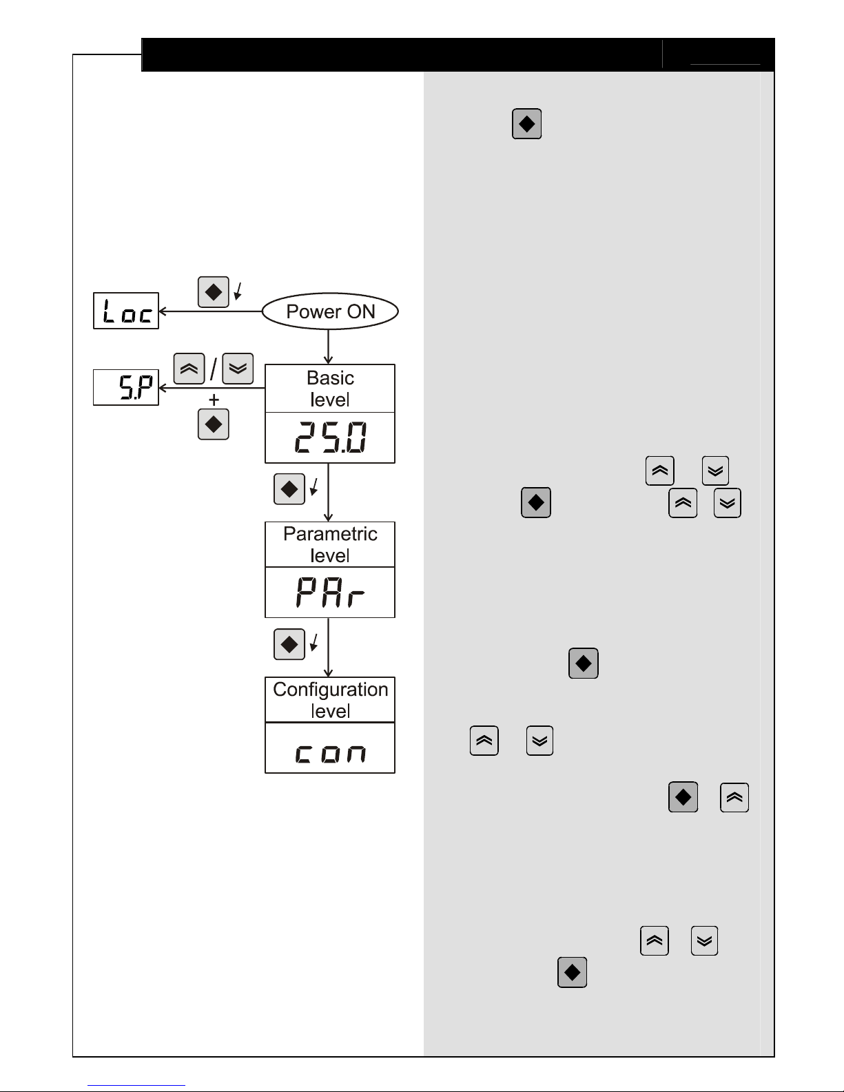
Access control (Hidden level)
♦ Hold
pressed while turning
the power supply on and until
Loc appears.
♦ Set keyboard locking mode
by assigning a corresponding value
to the Lock Keyboard parameter.
Basic level
At power-on, RT38 enters Basic level.
At this level, the device indicates
the measured input value (PV)
with a resolution, according to
the Point Position parameter.
Set-point adjustment
♦ To view the current Set Point value,
press and hold either or .
♦ Press
while holding
/
to enter Set Point adjustment mode.
Parametric level
This level contains the control algorithm
parameters.
♦ Enter from Basic level by pressing
and holding until PAr appears
on the display. Release the key.
♦ Choose a parameter using
or
.
♦ To enter parameter value
adjustment mode, press + .
♦ If no key has been pressed
for a while, the device automatically
returns to Basic level, storing all
confirmed changes.
♦ For quick exiting and saving,
use key combination +
or
hold down (for case 'M').
Message Sto confirms
the adjustments.
Page 9
Program Levels
9
Configuration level
This level contains
the configuration parameters
of the device.
♦ Enter from Basic level
by pressing and holding
until con appears.
♦ To access and adjust
the configuration parameters,
follow the algorithm described
in 'Parametric level'.
Output Control
Control output operation
♦ The control output operates
according to the control
algorithm parameters.
♦ When an error is detected
(see 'Error messaging'),
the output deactivates.
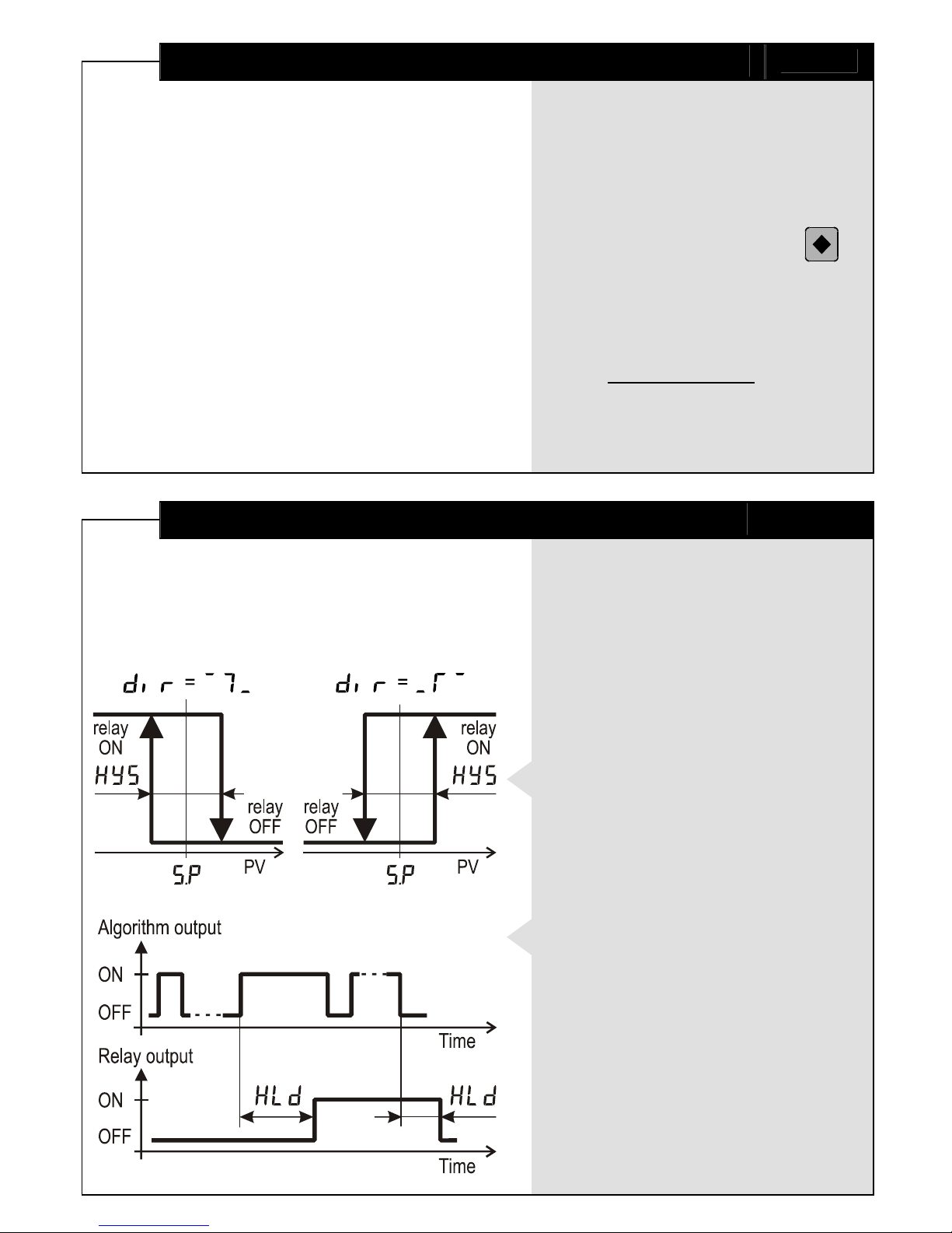
ON/OFF control algorithm
The static characteristic
of a relay controlled
by an ON/OFF algorithm
is shown on the left drawing.
Output hold
For eliminating undesirable
output switches, additional
parameter (Hold) is assigned
to hold the output reaction
for certain period of time.
Page 10

Input Filtration
10
Low-pass filter
This first-order filter acts ONLY within
a certain band around filter output value.
This has been designed to cut periodic
noises outside the communication signal
spectrum.
♦ Filter operation is defined by two
parameters:
Filter Time (defines filter time constant) and
Filter Band (defines filter active band
around filter output value).
♦ If the newly measured value differs
from the filter output by more than
Filter Band, the filter resets
with a new initial output value
(newly measured value).
Error Messaging
♦ {+} (over range) -
display value over 999
or sensor damaged (broken).
♦ <_> (under range) -
display value under -199
or sensor damaged (shorted out).
♦ FAL (fail) -
device memory error;
if error still exists after restart,
the unit must be returned for repair.
♦ Wmc (not calibrated) -
all factory calibrations are set to default
and the accuracy can not be guaranteed!
♦ W%P (error in Set Point) -
incorrect Set Point value;
check and readjust.
♦ WHS (error in Hysteresis) -
incorrect Hysteresis value;
check and readjust.
♦ --- (noise / initial check) -
too noisy input signal;
also shows the initial device check
at power-on.
Page 11
Declaration of Conformity
11
The undersigned hereby declares,
on behalf of COMECO Inc.,
that this device has been manufactured
in compliance with standards
EN 61000, EN 61010, and EN 61326,
and meets the requirements of Directives
2004/108/EC, 2006/95/EC, and 2011/65/EC.
Vladimir Sakaliyski, CEO
COMECO Inc.
Waste Disposal
Do not dispose of
electronic devices
together with
household waste
material!
If disposed of within European Union,
this product should be treated
and recycled in accordance with the laws
of your jurisdiction implementing
the WEEE Directive 2002/96
on the Waste Electrical and Electronic
Equipment.
Page 12
Specifications
12
Case
Input
Output
Power Supply
Excitation Voltage
Consumption
Measurement Error
Temperature Drift
Ambient Temperature / Humidity
Protection Class: front / terminals
'B', 'H', 'V', 'S', 'L', 'M', 'R'
RTD, thermocouple,
current, voltage
relay 5A/250VAC with NO/NC or NO contact,
SSR 1A/250VAC, SSR 0.2A/250VAC,
MOS gate 0.1A/60V, optically isolated,
5...24 VDC, 30 mA for external SSR
230 VAC, 90…250 VAC/DC,
24 VDC, 12...24 VAC/DC,
9 VAC, .....................................
≤ Up (DC); ≤1.2*Up (AC), 24 VDC, 30 mA,
.............................................
less than 1.5 VA
≤ ± 0.3% from span
≤ ± 0.02% from span for 1 °C
-10…65 °C / 0…85% RH, non-condensing
IP65, IP54, IP44 / IP20
Warranty and Support
………………………….
serial number
………………………….
manufacturing date
QC check mark …….……(passed)
(stamp)
88 Slavyanska Str.
P.O.Box 378
Plovdiv 4000, BULGARIA
tel: +359 32 646523, 646524
fax: +359 32 634089, 646517
e-mail: [email protected]
QD-8.2.4-WC
Warranty
COMECO warrants this product
to be free from defects in materials
and workmanship for 2 years. If your unit
is found to be defective within that time,
we will promptly repair or replace it.
This warranty does not cover accidental
damage, wear or tear, or consequential
or incidental loss. This warranty
does not cover any defects caused
by wrong transportation, storage, installation,
or operating (see 'Specifications').
Technical support
In the unlikely event that you encounter
a problem with your COMECO device,
please call your local dealer or contact
directly our support team.
 Loading...