

Page 1
Specifications
16
Case
Input
Outputs:
Electromechanical relay
SSR
MOS gate
Output for external SSR
- K1
- K2
Serial Interface
Power Supply
Excitation Voltage (Vaux)
Consumption
Measurement Error
Temperature Drift
RTD Line Error
Cold-junction Error
Operating Temperature / Humidity
Protection Class: front / terminals
'B', 'H', 'V', 'Q', 'S',
'L',
'R1', 'R2'
programmable
up to 2
5A/250VAC with NO/NC or NO contact
1A/250VAC, 0.2A/250VAC
0.1A/60V, optically isolated
5...24 VDC, 30 mA
relay, SSR, MOS gate, for ext. SSR
relay, SSR, MOS gate, for ext. SSR
RS485, isolated,
RS485 for "PolyMonitor", isolated
230 VAC, 90…250 VAC/DC,
24 VDC,
12...24 VAC/DC,
...................................
10...30 V, 30 mA, ........................
less than 3 VA
≤ ± 0.3% from span
≤ 0.02% from span for 1 °C
≤ ± 0.001%/Ω at R
lin
.
≤ 50 Ω
≤ ± 1 °C at air temperature -10…80 °C
-10…65 °C / 0…85% RH
IP65, IP54 / IP20
Warranty and Support
………………………….
serial number
………………………….
manufacturing date
QC check mark …….……(passed)
(stamp)
88 Slavyanska Str.
P.O.Box 378
Plovdiv 4000, BULGARIA
tel: +359 32 646523, 646524
fax: +359 32 634089, 646517
e-mail: [email protected]
QD-8.2.4-WC
Warranty
COMECO warrants this product
to be free from defects in materials
and workmanship for 2 years. If your unit
is found to be defective within that time,
we will promptly repair or replace it.
This warranty does not cover accidental
damage, wear or tear, or consequential
or incidental loss. This warranty
does not cover any defects caused
by wrong transportation, storage, installation,
or operating (see 'Specifications').
Technical support
In the unlikely event that you encounter
a problem with your COMECO device,
please call your local dealer or contact
directly our support team.
COMECO Inc., P.O.Box 378, Plovdiv 4000, BULGARIA, tel: +359 32 646523, 646524, fax: 634089
e-mail: [email protected], WWW .COMECOGROUP.COM
RT284U
wi t h k eyboard
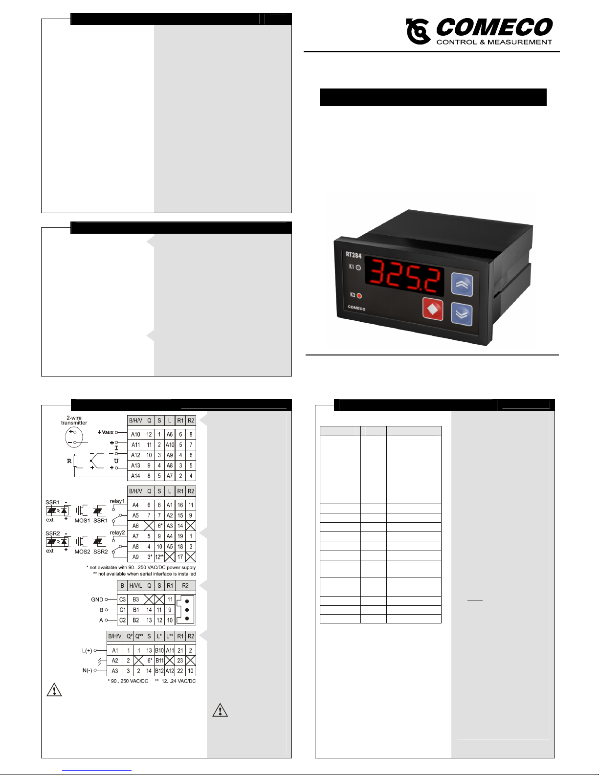
OP E RATIO N MA N U AL
Please read this Operation Manual before mounting and operating!
Save the Manual for future references!
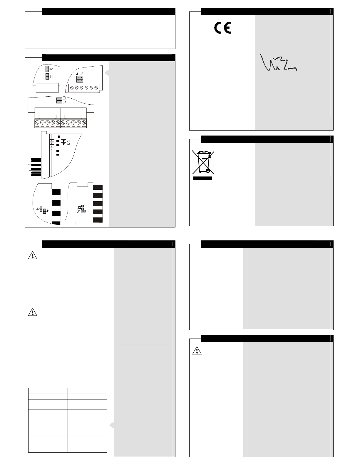
Wiring
4
Important notes:
♦
Strictly observe the requirements
for RS485 network building!
♦
With DC power supply,
the polarity does not matter.
♦
In case of 90...250 VAC/DC power supply,
grounding the device via separate wire
is mandatory for covering safety standards.
Input signal wiring
Connect the input
with regard to its type
through the respective and
depending on the case type
(see 'Specifications')
terminals on the device
back.
3-wire current
transmitters can be
supplied from Vaux.
Voltage transmitters must
be supplied externally!
Output wiring
Connect the outputs
with regard to their types
(see 'Specifications')
via the respective terminals.
RS485 wiring
Connect the unit
to RS485 network line
via the respective
terminals (connector).
Power supply wiring
Connect the right
power supply voltage
for your device
(see 'Specifications').
More detailed
wiring diagrams
are available at
comecogroup.com under
'Support' tab.
Communication Protocol
13
Table 2
Parameter Symbol
Value
Input Type
inp
pt100, pt1000,
ptc1, ptc2,
r.0.1k,
t.c.b, t.c.j,
t.c.k, t.c.r,
t.c.s, t.c.t,
u, u.0.10,
i.0.20, i.4.20
Unit
unit
c, f
Point Position
pnt
0, 1, 2, 3
Input Low
i.hi
-1999...9999
Input High
i.lo
-1999...9999
Input Correction
i.cor
-1999...9999
Address
addr
1...254
Baud Rate
baud
1200, 2400,
4800, 9600
Gradient
grad
0...9999
Filter Time
f.t
0...9999
Filter Band
f.b
0...M
Input Value
p.v
*
Error Info
error
**
* Input Value (read-only)
numerical value with ISU
- measured input value
sat.lo
- ADC under-range
sat.hi
- ADC over-range
inp.br
- sensor break
break
- device failure
noise
- noisy measurement
** Error Info
0
- initializes non-volatile memory
-1
- error FAiL (read-only)
1...29
- errors ER01... ER29 (read-only)
Protocol architecture
♦
The protocol is based
on UART protocol with:
Baud Rate - as defined
by parameter Baud Rate;
Data bits - 8;
Parity Control - Even;
Stop bit - 1.
♦
ASCII protocol is used
for communicating,
and the information
is exchanged in frames.
♦
Each frame consists of 1,
or 2 words separated
by byte 32 (SPACE),
and ends with bytes 13 (CR)
and 10 (LF). The first word
in the frame denotes
a parameter 'Symbol'
as taken from Table 2 and
the second word (if needed)
is the parameter 'Value',
both spelled with only
small Latin letters, digits,
dots, and/or the '-' sign.
Device activating
♦
To respond to commands,
the device should be active.
♦
For a device to be activated,
it must receive a Uх
command, where 'х' is
the value of the parameter
Address or the value '255' (if
device address is unknown),
and respond to it with ok..
♦
If a device does not respond
even to U255, check
the UART protocol settings,
chiefly Baud Rate value.
PROGRAMMABLE CONTROLLER
v
27-05.12
Page 2
Overview
2
RT284U is a low-cost multifunctional programmable controller. Its universal input
accepts the most common RTDs, thermocouples, and linear signals. The device can
be equipped with up to 2 relay outputs, which can control various actuators using
ON/OFF control algorithm, and the optional RS485 interface enables networking.
RT284U allows adjusting of the built-in digital filters and the programmable output
delay, resulting in increased operation reliability in case of industrial interferences.
Input Setting
♦
Open the case.
♦
Follow the diagrams on the left
to find the configuration jumpers
J1 and J2, located on the main
board (cases 'B', 'H', 'V', 'L', 'R1'
and 'R1') or on the outer side of
the right board
(cases 'Q' and 'S').
♦
To set input 0...10 V,
short out J2.
♦
To set any of the other
possible input types,
short out J1.
Declaration of Conformity
15
The undersigned hereby declares,
on behalf of COMECO Inc.,
that this device has been manufactured
in compliance with standards
EN 61000 and EN 61010,
and meets the requirements of Directives
2004/108/EC and 2006/95/EC.
Vladimir Sakaliyski
CEO
COMECO Inc.
Waste Disposal
Do not dispose of
electronic devices
together with
household waste
material!
If disposed of within European Union,
this product should be treated
and recycled in accordance with the laws
of your jurisdiction implementing
the WEEE Directive 2002/96
on the Waste Electrical and Electronic
Equipment.
Communication Protocol
14
Notes:
♦
RT284U adds 3 spaces
in the beginning of the response.
♦
RT284U returns decimal point
even when the value is integer.
♦
#13 (CR) is byte 0x0D;
#10 (LF) is byte 0x0A.
♦
The U255 command should be used
only in case just one slave is presented.
Protocol examples:
PC or other device:
RT284U response:
activating device number 10
U10#13#10 ok.#13#10
reading filter time
f.t#13#10 f.t 0015.#13#10
writing filter time of 30
f.t 30#13#10 f.t 0030.#13#10
reading input value of 27.5
p.v#13#10 p.v 027.5#13#10
invalid command.
command not recognized
parity error.
parity error detected
not a number.
attempt to write symbols
for numerical parameter
point error.
value resolution greater
than parameter’s one
out of range.
value out of range
unit is busy.
writing is allowed only
to device at Basic level
read only.
parameter is read-only
can't save.
problem with writing
in non-volatile memory
♦
The device remains active
until it receives another Uх
command, but with different
device address, a FAiL
error, or with reset.
♦
Any Baud Rate value change
through the communication
interface also deactivates
the device.
Reading from a device
♦
If the frame consists of only
one word, it is recognized
as a command for reading.
♦
The device responds to it by
returning the same word and
its value, according to Table 2.
Writing in a device
♦
If the frame consists of
two words, it is recognized
as a command for writing.
♦
With writing, transferred
are the same two words
that would have been
received at the respective
command for reading
from the device.
♦
After successful writing,
the device responds with
the respective command
for reading, except for
the baud command.
Other device responses
♦
When Error Info value is -1,
the device substitutes any
command for error reading.
♦
RT284U responses in case
of incorrect protocol use
are given on the left.
Reset
To reset the device,
send command reset.
Mounting
3
Panel mounting ('B' / 'H' / 'V' / 'Q' / 'S' / 'L')
♦
Place RT284U into an appropriate panel cut-out.
♦
Tighten it into place using
the enclosed mounting bracket(s).
Rail mounting ('R1')
♦
Insert the upper rail edge into the upper
plastic groove of the rail-installing
mechanism on the back side of the unit.
♦
Press the unit towards the lower
rail edge until the moving part
of the installing mechanism clicks.
Rail mounting ('R2')
The device can be easily mounted on every
35 mm rail conforming to EN50022 by the means
of a standard UNDECAL socket base.
Electro-Magnetic Interference (EMI) Issues
Important note:
A built-in RC noise
suppression circuit is
connected in parallel
with relay contacts.
Full AC voltage
isolation is NOT
provided when relay
contacts are open.
Small AC current
(≈ 1.5 mA at 230 VAC)
still flows through
the RC circuit!
♦
All signal wires must be shielded. They must
not be packaged together with power cables!
♦
Never lay the signal wires close to inductive
or capacitive noise sources, such as relays,
contactors, motors, etc.!
♦
All shields have to be grounded ONLY at one end,
as closer as possible to the controller terminals!
♦
Avoid sharing supply lines with powerful
consumers, especially with inductive loads,
switched on and off.
♦
To stop unwelcome interference signals
entering through the power supply lines,
use shielded 1:1 isolation transformer!
♦
Shunt all switched (not only those switched
by the controller) inductive consumers with
special suppression networks: RC group and
varistor - for AC loads, or diode - for DC loads.
♦
If the controller operates in a very powerful
EMI area, it has to be mounted inside
a grounded metal shielding box!
♦
To protect the interface from electro-magnetic
disturbances, follow the RS485 standard
guidelines.
'B' / 'H' / 'V'
'R1'
'L'
'Q'
'S'
'R2'
Page 3
Parameter Symbol Description
Configuration Parameters
(These parameters are part of Configuration level)
Input Type
inP
Type of signal that can be connected to the device input
Unit
unit
Temperature measurement unit
Point Position
Pnt
Display decimal point position
Input Low
ILo
Display value at low limit of the linear input range
Input High
IHi
Display value at high limit of the linear input range
Input Correction
Icor
Constant to be added to the measured input value
Address
Addr
Device address
Baud Rate
bAud
Serial interface rate
Gradient
GrAd
Maximum input signal change during the sampli ng period (120 ms)
Filter Time
\t
Relative time constant of the input filter
Filter Band
\b
Zone around the measured value, within which the filter is active
SP limit Low
%[L
Set-point Low limit
SP limit High
%[H
Set-point High limit
Direction 1
diR1
Control action direction of output K1
Direction 2
diR2
Control action direction of output K2
Parameters of the control algorithm
(These parameters are part of Parametric level)
+ Differential 1
[e1
Positive Differential of output K1
- Differential 1
me1
Negative Differential of output K1
Time On 1
ym1
ON duration of output K1
Time Off 1
y\1
OFF duration of output K1
Hold 1
HLe1
Holds the output reaction of output K1
The same 5 parameters, but with index 2 - for output К2
Parameters of Basic (operating) level
Set Point 1
%[1
Set-point value of output K1
Set Point 2
%[2
Set-point value of output K2
Input Filtration
11
Peak filter
This filter is intended for eliminating
pulse spikes (peaks), which can appear
in the input signal, in the following way:
♦
RT284U measures the input signal
value every 120 ms (sample time).
♦
The measured values are compared
subsequently. The filter checks
the difference between the last
two samples. If it does not exceed
Gradient value, the device accepts
the signal as normal.
♦
If the last measured value differs
from the previous one by more than
the Gradient value, the filter output is held
until the device determines a presence
of a normal signal. It is possible only
if the input signal has not been changed
with more than the Gradient value
for four subsequent samples.
♦
If the device has not determined
a normal signal for 20 subsequent
samples, noiS appears on the display
(see 'Basic level').
Low-pass filter
This first-order filter acts ONLY within
a certain band around filter output value.
This has been designed to cut periodic
noises outside the communication signal
spectrum.
♦
Filter operation is defined by two
parameters:
Filter Time (defines filter time constant) and
Filter Band (defines filter active band
around filter output value).
♦
If the newly measured value differs
from the filter output by more than
Filter Band, the filter resets
with a new initial output value
(newly measured value).
Output Control
10
Control output operation
♦
The control outputs
operate according
to the control algorithm
parameters.
♦
The outputs deactivate
with the value change
of one of the following
configuration
parameters - Point
Position, Input Low, Input
High, and Input Correction
- and remain inactive till
Basic level is entered.
♦
The outputs deactivate
also when an error
has been detected
(see 'Error messaging').
ON/OFF control algorithm
The static characteristic
of a relay controlled
by an ON/OFF algorithm
is shown on the left drawing.
Output hold
For eliminating undesirable
switches of the relay output,
additional parameter (Hold)
is assigned to hold
the output reaction
for certain period of time.
Output pulse mode
When a relay is forced
to ON by the control
algorithm, it can either
stay ON or pulse
depending on Time On and
Time Off parameter values.
Setting any of these
parameters to '0'
disables the Pulse mode.
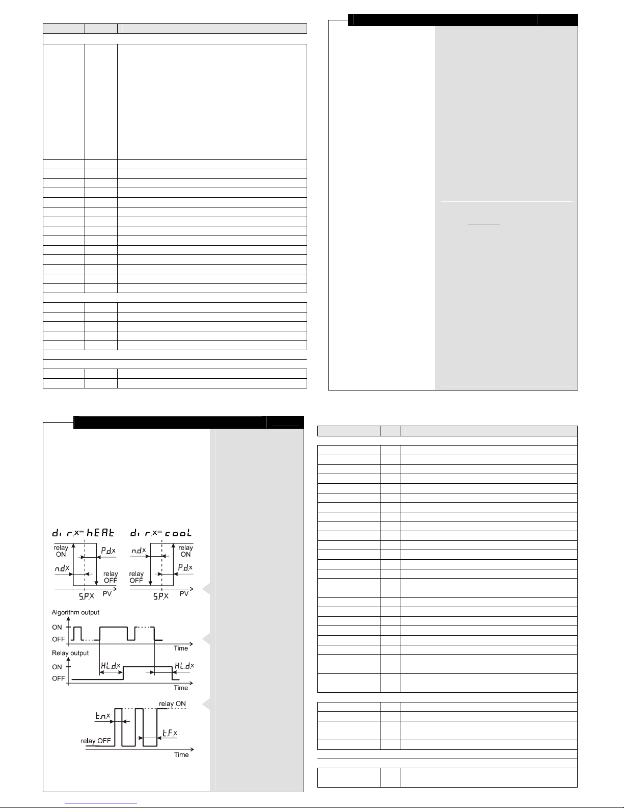
Table 1
Value Unit
Notes
Pyh or Pyt - Pt100: -100…850 °C or Pt1000: -100…600 °C
Ptx1 or Ptx2 - PTC 1k or 2k: -50...150 °C
R)1
- resistive linear: 0…1 kΩ
yc-b
- T/C "B": 200...1800 °C
yc-J
- T/C "J": -20...1000 °C
yc-"
- T/C "K": -20...1300 °C
yc-r
- T/C "R": 0...1700 °C
yc-S
- T/C "S": 0...1700 °C
yc-t
- T/C "T": -40...400 °C
u
- voltage linear: 0…100 mV
I)20 or I$20 - current linear: 0…20 mA or 4…20 mA
w)10
- voltage linear: 0…10 V
.Cor .F - °C or °F
x1, x0.1, x0.01, x0.001 - when indicating values with the input-signal measurement unit (ISU)
-1999 ... 9999 ISU These parameters make sense ONLY in case of a linear input signal!
-1999 ... 9999 ISU OFFSET
1…254 -
!2, @4, $8, (6 bps 1200, 2400, 4800 (factory-set), or 9600 bps
0 … 9999 ISU used for input peak filtration; Value '0' cancels the filtration.
0 … 9999 - This parameter and the following one define a low-pass input filter.
0 … M ISU
temperature: whole part of M ≤ 100; linear: M = 25% of input range
within input range ISU
These parameters keep the Set point in safe limits,
preserving it from random changes.
cooL, hEAt - ('cooling' , 'heating')
These parameters are accessible in the presence of the corresponding relay.
0 ... 9999 ISU lower than (High input range - Set Point 1)!
0 ... 9999 ISU lower than (Set Point 1- Low input range)!
0 ... 9999 sec. Value '0' disables Pulse mode.
0 ... 9999 sec.
These parameters are accessible in the presence of the corresponding relay.
within input range ISU
Page 4
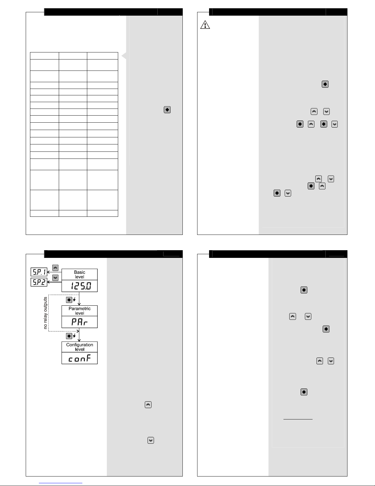
Error Messaging
12
Message Parameters Error type
FAiL
all
Incorrect
memory
br"
-
Service
required!
ER01 GrAd
Out of range
ER02 \t
Out of range
ER03 \b
Out of range
ER04 %[L
Out of range
ER05 %[H
Out of range
ER06
%[L, %[H
%[L> %[H
ER11, ER21 ym1, ym2 Out of range
ER12, ER22 y\1, y\2 Out of range
ER13, ER23 HLe1, HLe2 Out of range
ER14, ER24 [e1, [e2 Out of range
ER15, ER25 me1, me2 Out of range
ER16, ER26 %[1, %[2
Out of range
(%[L… %[H)
ER17, ER27
%[x - me x
Lower than
Input
Low Range
Limit
ER18, ER28
%[
x
+
[e
x
Exceeds
Input
High Range
Limit
ER29 Addr
Out of range
♦
In some cases,
RT284U finds
non-conformities
in parameter values
that must be corrected
before operating
at Basic level.
♦
The device indicates
such kind of problems
by displaying
error messages
as given on the left.
♦
If FAiL appears
on the display,
try debugging
by turning
the power off/on.
♦
If the problem persists,
press and hold or
send command error 0
via the communication
interface to restore
the default (factory)
settings.
Parameter Programming
5
Some parameters
are accessible only
when the respective
functionality is installed.
(see 'Specifications').
- Changing
Point Position value
reflects the real value
of all parameters
with ISU!
E.g.: changing
Point Position value
from (х1) to (х0.1)
would change
a Set-point value
of 100 to 10.0!!!
Controller parameters
RT284U is a programmable device whose
service behavior is determined by a set
of parameters. All the parameters, along
with their names, symbols, and value ranges,
are given in Table 1.
Setting numerical parameter value
♦
Enter parameter value adjustment mode
(see 'Program Levels').
♦
The whole part of the value together with
the left zeroes appears on the display,
and the rightmost digit blinks.
♦
To select another digit, press .
♦
The 3 rightmost digits can accept values
from 0000 to 9999, and the leftmost digit
can also accept the values ---- and ````.
♦
To increase or decrease the blinking digit
value, use respectively or .
♦
Confirm the adjusted value by pressing
simultaneously
+
or
+
.
♦
If the new value has not been confirmed
and no key has been pressed for a certain
period of time, value adjustment
automatically ceases, and the parameter
retains its initial value.
Setting symbolic parameter value
♦
Enter parameter value adjustment mode
(see 'Program Levels').
♦
Read the blinking parameter value.
♦
To change the value, use or ,
and to confirm, press
+
or
+
.
♦
If the new value has not been confirmed
and no key has been pressed for a certain
period of time, value adjustment
automatically ceases, and the parameter
retains its initial value.
Program Levels
8
Basic level
At Basic level, RT284U indicates
the measured input value (PV)
with a resolution, according to
the Point Position parameter.
♦
If the whole part of PV cannot be
entirely displayed, the unit
generates blinking 'overflow'
messages (oL or -oL,
depending on PV sign).
♦
If PV is out of its operating range
(the input range according
to Table 1, extended by 5%
on both sides), the device displays
blinking symbolic messages:
<__> (under-range) or
{++} (over-range).
When PV is out of physical range,
the unit displays ----.
♦
Upon entering Basic level,
RT284U may display
the init message,
indicating that some time
is necessary for filter initialization.
♦
The noiS message may appear
as a result of the peak filter
operation (see 'Input filtration').
♦
To enter parameter value
adjustment mode for Set Point 1,
press and hold until %[1
appears on the display.
To view the Set-point value,
release the key.
♦
To enter parameter value
adjustment mode for Set Point 2,
follow the same procedure,
but start with the key.
Program Levels
9
Parametric level
This level contains the control
algorithm parameters. If no relay output
is installed, this level does not show up.
♦
Enter from Basic level by pressing
and holding until PAr appears
on the display. Release the key.
If the key is not released on time,
RT284U enters Configuration level.
♦
Choose a parameter
using and .
♦
To enter parameter value
adjustment mode, press .
♦
If no key has been pressed
for a while, the device automatically
returns to Basic level, storing all
confirmed changes.
♦
For quick exiting and saving,
use key combination + .
Configuration level
This level contains the configuration
parameters of the device.
♦
Enter from Basic level by pressing
and holding until conF
appears on the display.
♦
To access and adjust
the configuration parameters,
follow the algorithm described
in 'Parametric level'.
 Loading...