

Page 1

Digital Telephone System
System Manual
For The Impact DSU
This publication is applicable to the following equipment:
G0408, with software I0408, revision 18A and later
G0816, with software I0816, revision 18A and later
G1632, with software I1632, revision 18A and later
Supports Impact, Impression, DigiTech,
and Scout Telephones
R
Page 2

Printed in U.S.A. GCA47-157
Page 3

Digital
Telephone
System
System Hardware And
Software Instructions
Supports
For the
This publication is applicable to the following equipment:
G0408, with software I0408, revision 18A and later
G0816, with software I0816, revision 18A and later
G1632, with software I1632, revision 18A and later
Impact
, Impression, DigiTech, and Scout
Impact
Telephones
DSU
Printed in U.S.A. IMI66–107.04
R
10/96
Page 4
CERTIFIED
ISO 9001
C
A
R
Accredited bythe Dutch Council
for Accreditation for certification
and registration activities.
C
E
N
R
O
I
T
T
I
A
I
C
F
E
Comdial's Quality Management System Is
Certified To The ISO 9001 Standard.
E
R
C
ANSI-RAB
G
I
S
D
I
T
E
D
R
A
R
T
Comdial strives to design the features in our communications systems to
be fully interactive with one another. However, this is no t always possible,
as the combinations of accessories and features are too varied and extensive
to insure total feature compatibility. Accordingly, some features identified
in this publication will not operate if some other feature is activated.
Comdial disclaims all liability relating to feature non-compatibility or
associated in any way with problems which may be encountered by
incompatible features. Notwithstanding anything contained in this
publication to the contrary, Comdial makes no representation herein as to
the compatibility of features.
2/12/97
Page 5

IMI66–107 Digital Telephone System
Introducing The
1
Section Title............................................................................................ Page
1.1 Using This Manual......................................................................................12
1.2 Using Related Publications.........................................................................13
1.2.1 Locating User Information ......................................................................13
1.3 Accessory Information................................................................................15
1.3.1 The Analog Terminal Interface .............................................................. 15
1.3.2 Headset Operation ...................................................................................15
1.3.3 Battery Back Up ......................................................................................16
1.3.4 DSS/BLF Console ...................................................................................16
1.3.5 Caller ID ..................................................................................................16
1.3.6 Tracker.....................................................................................................16
Digital Telephone System
1.3.7 DVA.........................................................................................................16
1.3.8 DIU..........................................................................................................16
1.4 Hardware Summary...................................................................................17
1.5 Common Equipment Description..............................................................18
1.6 Station Descriptions..................................................................................110
1.6.1 DigiTech Telephone Descriptions.........................................................110
1.6.2 Impact Telephone Descriptions.............................................................112
1.6.3 Impression Telephone Descriptions ......................................................114
1.6.4 Station Controls and Indicators .............................................................116
1.7 General Specifications ..............................................................................119
1.7.1 Feature Codes ........................................................................................122
1.7.2 System Ringing Patterns........................................................................124
1.8 Seeking Repair Assistance........................................................................125
Introducing The DSU 1 – 1
Page 6

Digital Telephone System IMI66–107
1.1 Using This Manual
This publication contains a technical discussion of the digital telephone system; it provides
step-by-step instructions for installation and programming. If you are unfamiliar with the
equipment, read this manual at least once before you attempt to install and program the system.
The five chapters in this manual are as follows.
Chapter One, Introducing The Digital Telephone System, is a general description of the
•
digital telephone system, the supporting documentation, and the equipment hardware.
Chapter Two, Installing The Digital Telephone System, contains installation instructions
•
and connection details.
Chapter Three, Programming The Digital Telephone System, gives you instructions for
•
setting the operating parameters of the system.
Chapter Four, Recording The Programming Information, contains charts for recording
•
programming decisions.
Appendix A, Describing The System Features, details features the digital telephone system
•
offers.
1 – 2 Introducing The DSU
Page 7

IMI66–107 Digital Telephone System
1.2 Using Related Publications
The following publications contain information applicable to the digital telephone system.
Should you need copies of these publications, contact your Comdial inside sales representative.
Comdial
Inside Sales Department
P.O. Box 7266
Charlottesville VA 22906
Call: 1-800-347-1432
1.2.1 Locating User Information
Working With Electrostatically Sensitive Components
IMI 01-005 Handling of Electrostatically Sensitive Components
Operation With DigiTech Telephones and Consoles
These user guides are for DigiTech telephones with product codes 7700S, 7714X, and 7714S,
with revision A through H, and console DD32X.
GCA70183 DigiTech Multiline Telephone System Users Guide
•
GCA70182 DigiTech Attendants Guide
•
GCA70184 DigiTech Station Users Guide
•
GCA70232 DigiTech Single-Line Proprietary Telephone Users Guide
•
GCA70187 DigiTech DSS/BLF Console Users Guide
•
These user guides are for DigiTech telephones with product codes 7700S, 7714X, and 7714S,
with revision I and later, and console DD32X.
GCA70220 DigiTech LCD Speakerphone System Users Guide
•
GCA70221 DigiTech Multiline Telephone System Users Guide
•
GCA70228 DigiTech Attendants Supplement
•
GCA70232 DigiTech Single-Line Proprietary Telephone Users Guide
•
GCA70187 DigiTech DSS/BLF Console Users Guide
•
Introducing The DSU 1 – 3
Page 8

Digital Telephone System IMI66–107
Operation With Impact Telephones and Consoles
These user guides are for telephones with product codes 8024S, 8124S, 8012S, 8112N, 8101N,
and console IB64X.
GCA70245 Impact LCD Speakerphone System Users Guide
•
GCA70244 Impact Multiline Telephone System Users Guide
•
GCA70247 Impact Attendants Supplement
•
GCA70248 Impact Station Users Guide
•
GCA70246 Impact Single-Line Proprietary Telephone Users Guide
•
GCA70256 Impact DSS/BLF Console Users Guide
•
Operation With Impression Telephones
These user guides are for telephones with product codes 2022S, 2122S, 2122X, and 2101N.
GCA70328 Impression LCD Speakerphone System Users Guide
•
GCA70329 Impression non-LCD Speakerphone And Monitor Telephone System Users
•
Guide
GCA70330 Impression Single Line Proprietary Telephone Users Guide
•
GCA70332 Impression LCD Speakerphone Station Users Guide
•
GCA70 333 Impression non-LCD Speakerphone And Monitor Telephone Station Users
•
Guide
Operation With Industry-Standard Telephones Through The ATI-D
GCA70239 Users Guide For The Industry-Standard Telephone
•
IMI89037 Installation Instructions For The Analog Terminal Interface (ATI-D).
•
1 – 4 Introducing The DSU
Page 9

IMI66–107 Digital Telephone System
1.3 Accessory Information
The digital telephone system is capable of supporting several accessory software and hardware
devices. You can add voice mail, industry standard telephones, and headset capabilities to your
digital telephone system.
1.3.1 The Analog Terminal Interface
By employing the Analog Terminal Interface device (ATI-D), the digital telephone system can
support the operation of the following accessories:
ExecuMail and Versatile Voice Processing,
•
Industry-standard telephones and telephone devices.
•
For more information on the ATI-D, see section 2.19.2, Installing The Analog Terminal
Interface.
1.3.2 Headset Operation
The Comdial DigiTech speakerphones with product codes of 7700S, revision H and earlier,
include a built-in headset port. Speakerphones with a revision of I and later and Impact LCD
speakerphones with product code 8024S provide an auxiliary jack for headset interface.
Contact your Comdial Inside Sales Representative for a list of compatible headset
manufacturers.
NOTE: The system delivers subdued off-hook voice announce (SOHVA) messages to the headset
port. Because a telephone headset exhibits a coupling effect between the ear piece and
the microphone, it may allow the outside party to hear the SOHVA message.
Introducing The DSU 1 – 5
Page 10

Digital Telephone System IMI66–107
1.3.3 Battery Back Up
You can install an optional battery backup that provides power to the system in the event of a
power failure. For more information, see section 2.20.1, Installing The Battery Backup.
1.3.4 DSS/BLF Console
You can add a separate DSS/BLF console to provide additional DSS/BLF buttons to a particular
station (such as an attendant). These additional DSS/BLF buttons work just like the DSS/BLF
buttons on the telephone. For more information, see section 2.6, Installing The DSS/BLF
Console.
1.3.5 Caller ID
Using the Caller Identification Interface (product code CID08), the digital telephone system
provides caller ID information as part of the SMDR printout and as ASCII data input for use
with personal-computer-based application programs.
1.3.6 Tracker
With Tracker you can send messages to Tracker Pagers assigned to a station extension number.
When the pager is activated the user reads the message on the pagers LCD display. The system
delivers alpha/numeric or numeric-only messages depending on the Tracker Model being used.
1.3.7 DVA
Digital voice announcing uses a hardware peripheral device (product code DVA01) connected to
a digital station port to play recorded messages during an in-progress call. The DVA stores the
messages in its memory for recall when needed.
1.3.8 DIU
The Data Interface Unit (DIU) is a device connected to a digital station port of a DSU. The DIU
provides connections for a digital multiline telephone and another device such as a industry
standard telephone (IST), FAX, or modem. The DIU swithces the voice path from the DSU to
either the digital telephone or the IST by pressing a button on the digital telephone.
1 – 6 Introducing The DSU
Page 11
IMI66–107 Digital Telephone System
1.4 Hardware Summary
The digital telephone system consists of an electronic Digital Service Unit (DSU)usually referred
to as common equipmentoptional expansion modules to extend station and line capacities,
dedicated digital electronic key telephones, and interconnecting wiring consisting of small, 2- or
4-conductor, twisted-pair cable. The digital telephone system supports all Comdial proprietary
digital telephone models.
NOTE: Sxxxx software only supports DigiTech telephones; Ixxxx software supports all digital
telephones.
The station and line capacity of the base unit and optional expansion module are detailed in the
following chart.
Model
Number
G0408 4 8
G0816 8 16
G1632 16 32
GM408 4 8
CO/PBX
Capacity
Station
Capacity
Introducing The DSU 1 – 7
Page 12

Digital Telephone System IMI66–107
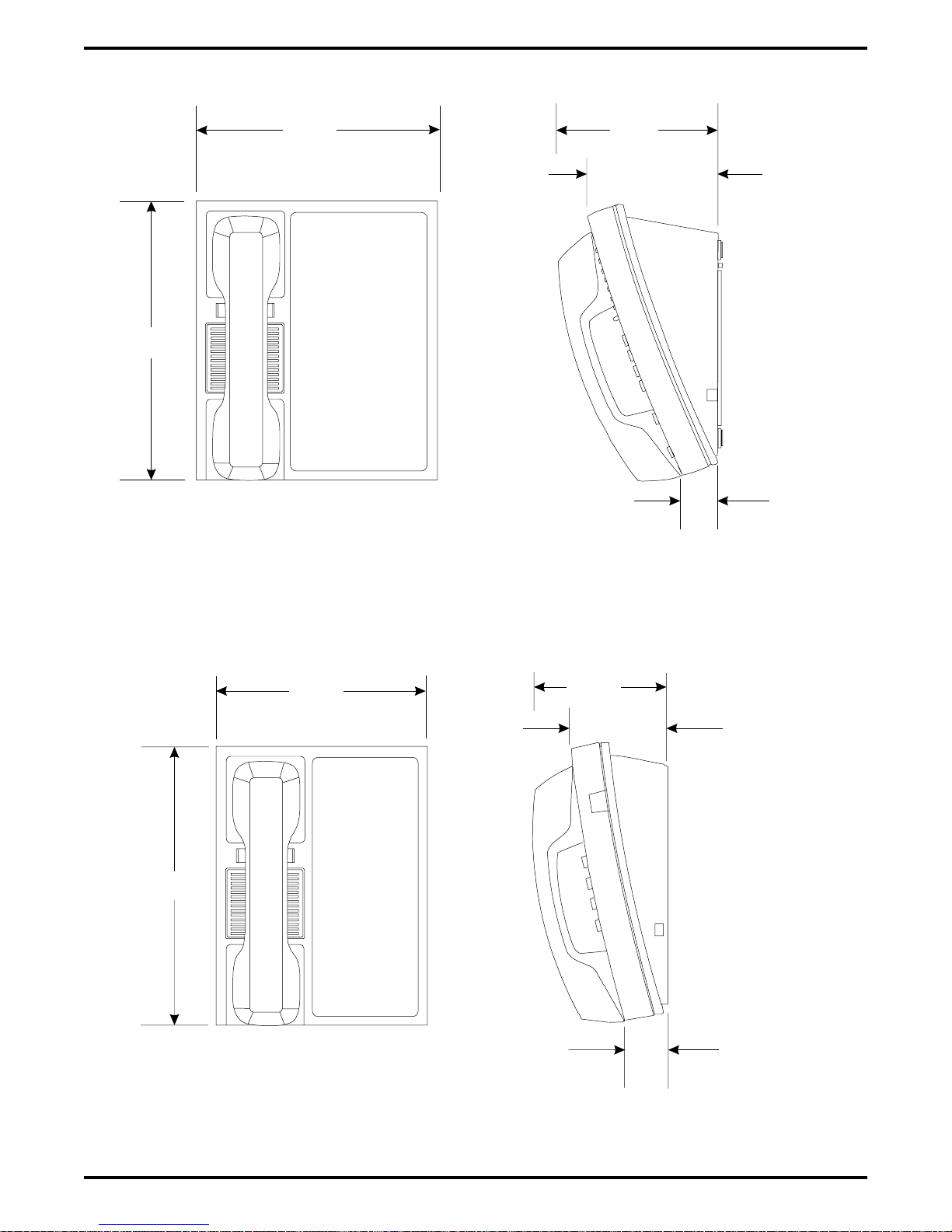
1.5 Common Equipment Description
The common equipment base unit is a fully electronic device. It is essentially a special purpose
computer system acting as a communications controller between central office (CO), private
branch exchange (PBX), or CENTREX supplied lines and the proprietary digital telephone
stations. The software design of the common equipment provides complete system support and
great flexibility of operation.
The system is fully digital with two usable time slots available for each station. Digital
information is computer-encoded voice transmission and control signals. After a computer
translates analog voice transmissions to digital information, the digital signals travel through
time division multiplexing (TDM) highways. The TDM highway can transmit several signals
over a single pair of wires at the same time. A system clock partitions TDM information into
time slots. A time slot is a portion of time assigned to a particular position of the system clock.
Each time a particular clock position is reached, the computer reads information associated with
that position. As the system clock goes through its cycle, the computer passes digital information
between pieces of equipment sharing time slots.
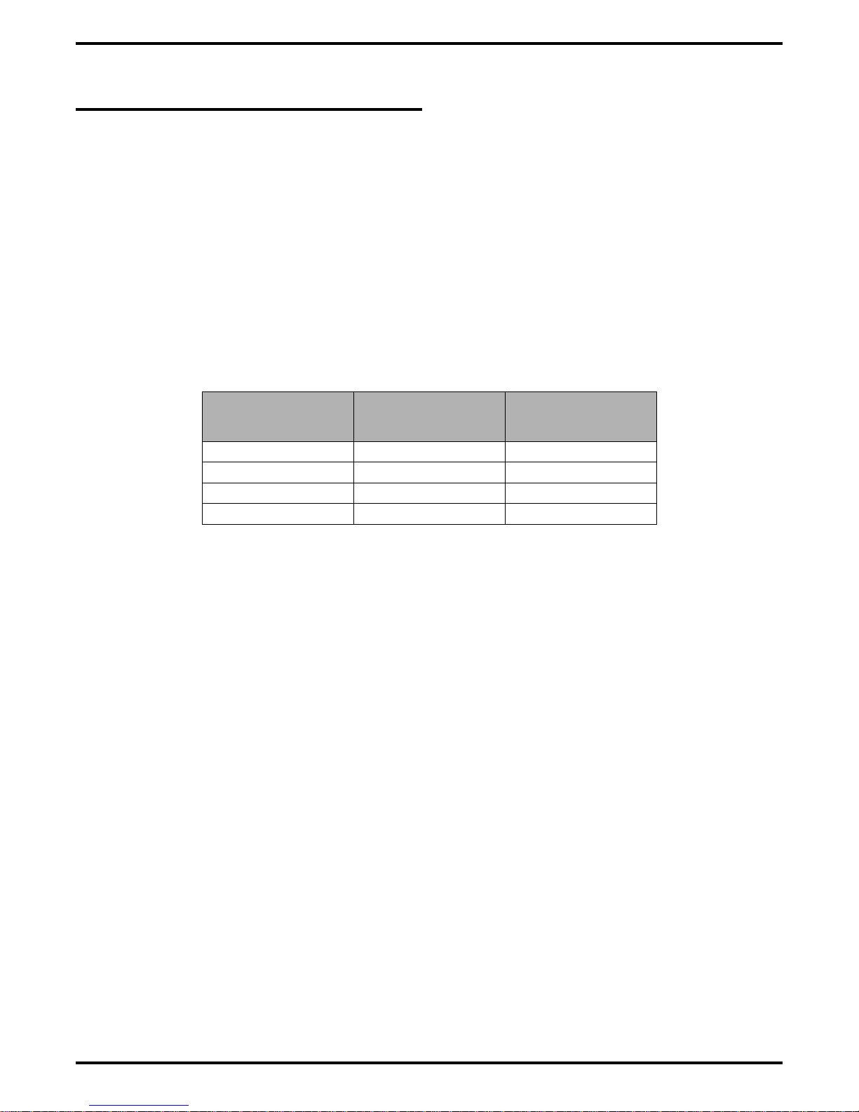
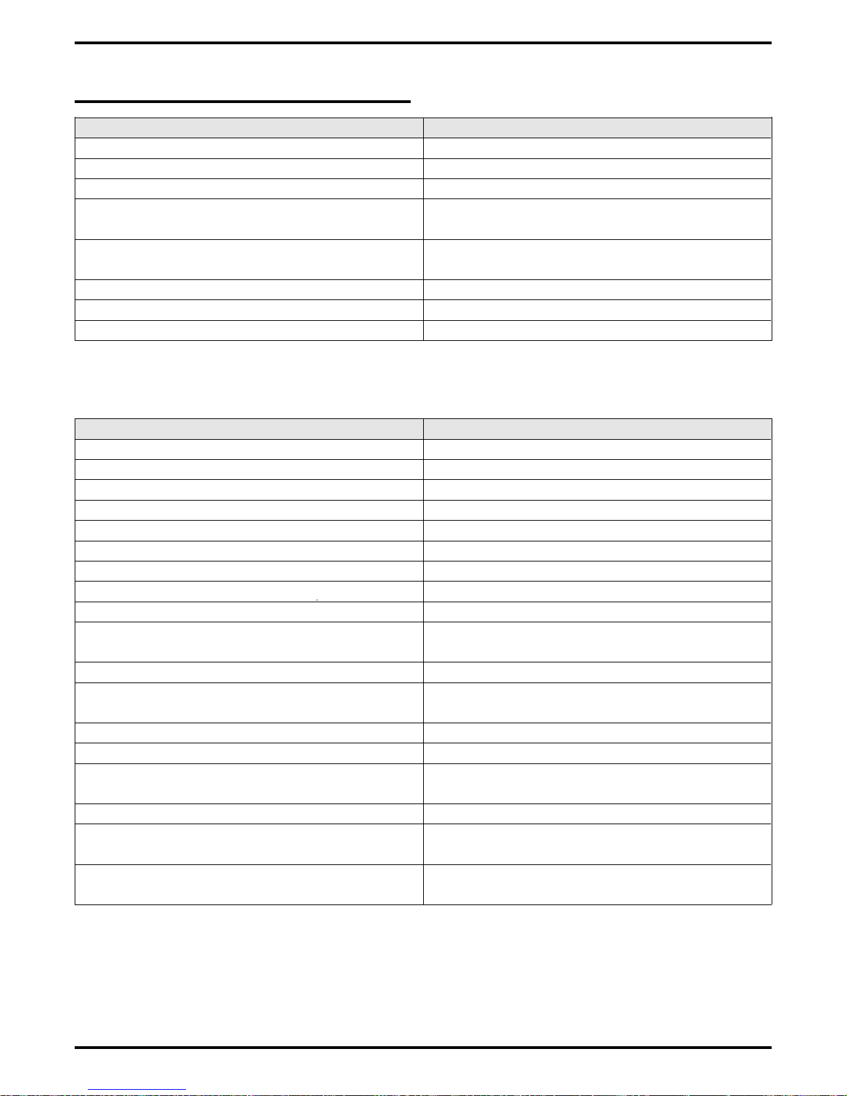
The common equipment consists of a base unit, which provides complete feature support, and
optional expansion modules for additional lines and stations. It is contained in a contemporary
metal housing designed to be inconspicuous in a modern office environment. It is engineered to
be wall or rack mounted.
1 – 8 Introducing The DSU
Page 13
IMI66–107 Digital Telephone System
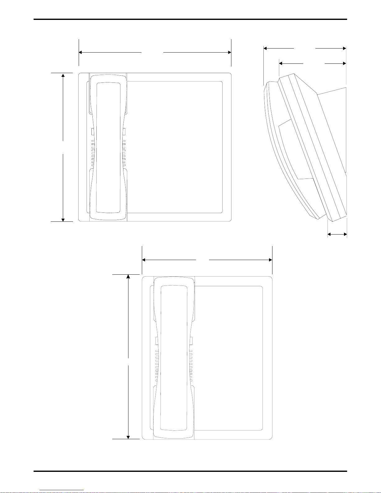
14.
"
7.
43"
7"
3.
13"
2.
16.5 "
4-Line, 8-Station Base Unit
2.5"
21.3 "
14. "
7.43"
54"
4.
7"
3.
13"
2.
16.5 "
26.25"
27.5 "
8-Line, 16-Station Base Unit
CAJS 74
14. "
7.43"
"
2.
16.5 "
26.25"
27.5 "
16-Line, 32-Station Base Unit
Figure 1–1: Common Equipment Dimensions
Introducing The DSU 1 – 9
Page 14
Digital Telephone System IMI66–107
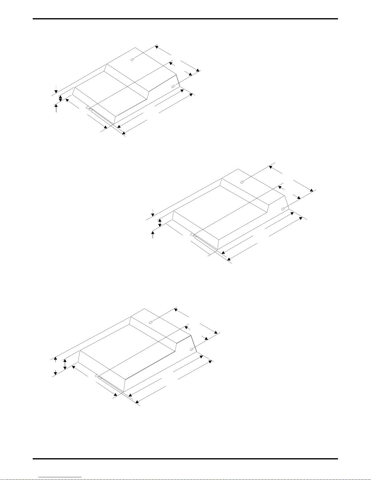
1.6 Station Descriptions
The digital telephones used with the digital telephone system are electronic,
microprocessor-controlled, devices. They allow not only multiline pickup but also single button
access to features available from the serving CO, PBX, CENTREX, or common equipment. The
digital telephones are available in several different styles with several models available in each
style. The following list details the available telephones.
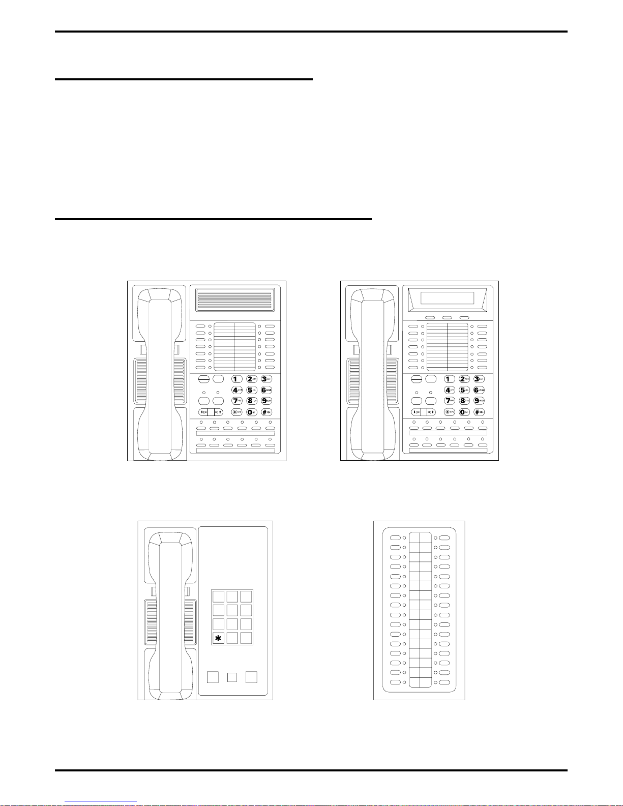
1.6.1 DigiTech Telephone Descriptions
CAJS075
COMDIAL
TRANS
TAP
CONF
MUTE
SPKR
HOLD ITCM
7714X Monitor Telephone
7714S Speaker Telephone
DIGITECH
COMDIAL
TRANS
TAP
CONF
MUTE
SPKR
HOLD ITCM
7700S LCD Speakerphone
12X14LCD
DIGITECH
HOLD
7701X Single Line Proprietary Telephone
1 – 10 Introducing The DSU
ABC
DEF
3
2
1
GHI
JKL
MNO
6
5
4
PRS
TUV
WXY
9
8
7
OPER
#
0
TAP
DD32X DSS/BLF Console
Figure 1–2: DigiTech Telephone Images
Page 15
IMI66–107 Digital Telephone System
.625"
7.65"
7714X
7714S
4.3"
4. 6"
77 S
1.112"
.625"
6.451"
4. 7"
77 1X
CAJS45
Figure 1–3: DigiTech Telephone Dimensions
2. 7"
1.251"
Introducing The DSU 1 – 11
Page 16
Digital Telephone System IMI66–107
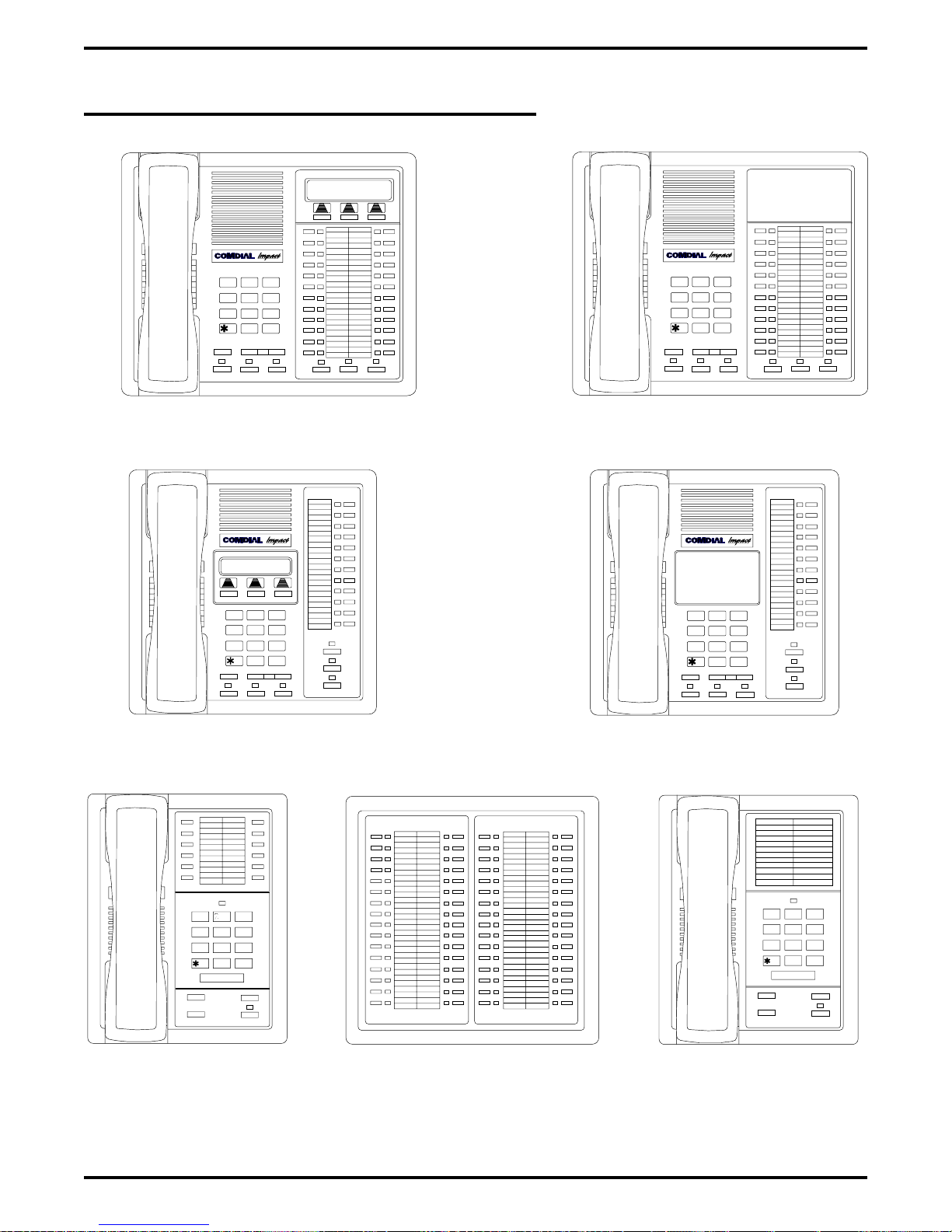
1.6.2 Impact Telephone Descriptions
DEFABCQZ
321
MNOJKL
GHI
5
6
4
TUVPRS WXY
87 9
OPER
0
#
TRNS/CNF
SPEAKER
INTERCOM
TAPHOLD
8024S LCD Speakerphone
DEFABCQZ
321
MNO
GHI
JKL
4
6
5
TUVPRS WXY
TRNS/CNF
HOLD
87 9
OPER
0
TAP
#
INTERCOM
SHIFT
MUTE
SPEAKER
DEFABCQZ
321
MNOJKL
GHI
5
6
4
TUVPRS WXY
87 9
OPER
0
#
TRNS/CNF
MUTESHIFT
TAPHOLD
SPEAKER
INTERCOM
MUTESHIFT
8124S Speakerphone
DEFABCQZ
321
MNO
GHI
JKL
4
6
5
TUVPRS WXY
TRNS/CNF
87 9
OPER
0
TAPHOLD
#
INTERCOM
SHIFT
MUTE
SPEAKER
8012S LCD Speakerphone
QZ
ABC DEF
1 2
3
GHI
4
6
5
JKL
TUV
PRS
8
7
9
0
OPER
#
COMDIAL
TRNS/CNF
HOLD
8112N Non-Monitor
MNO
WXY
INTERCOM
8112S Speakerphone
CAJS076
1 2
QZ ABC DEF
3
GHI
4
6
5
JKL
MNO
TUV
WXY
PRS
8
9
7
0
#
OPER
COMDIAL
TAP
IB64X DSS/BLF Console
TRNS/CNF
HOLD
8101N
TAP
INTERCOM
Single Line Proprietary Telephone
Figure 1–4: Impact Telephone Images
1 – 12 Introducing The DSU
Page 17
7
IMI66–107 Digital Telephone System
1 .75
7.13
1 1N,
.
24S, 124S
.
112N
CAJS 7
.
.
12S, 112S
4.64
3.731
1. 34
Figure 1–5: Impact Telephone Dimensions
Introducing The DSU 1 – 13
Page 18
Digital Telephone System IMI66–107
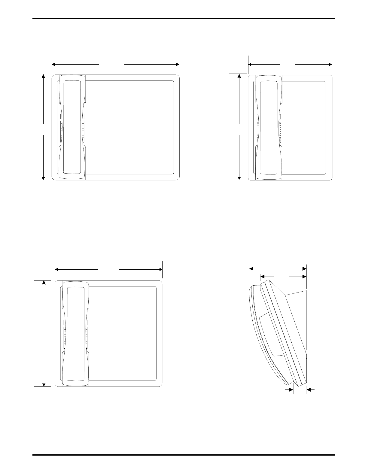
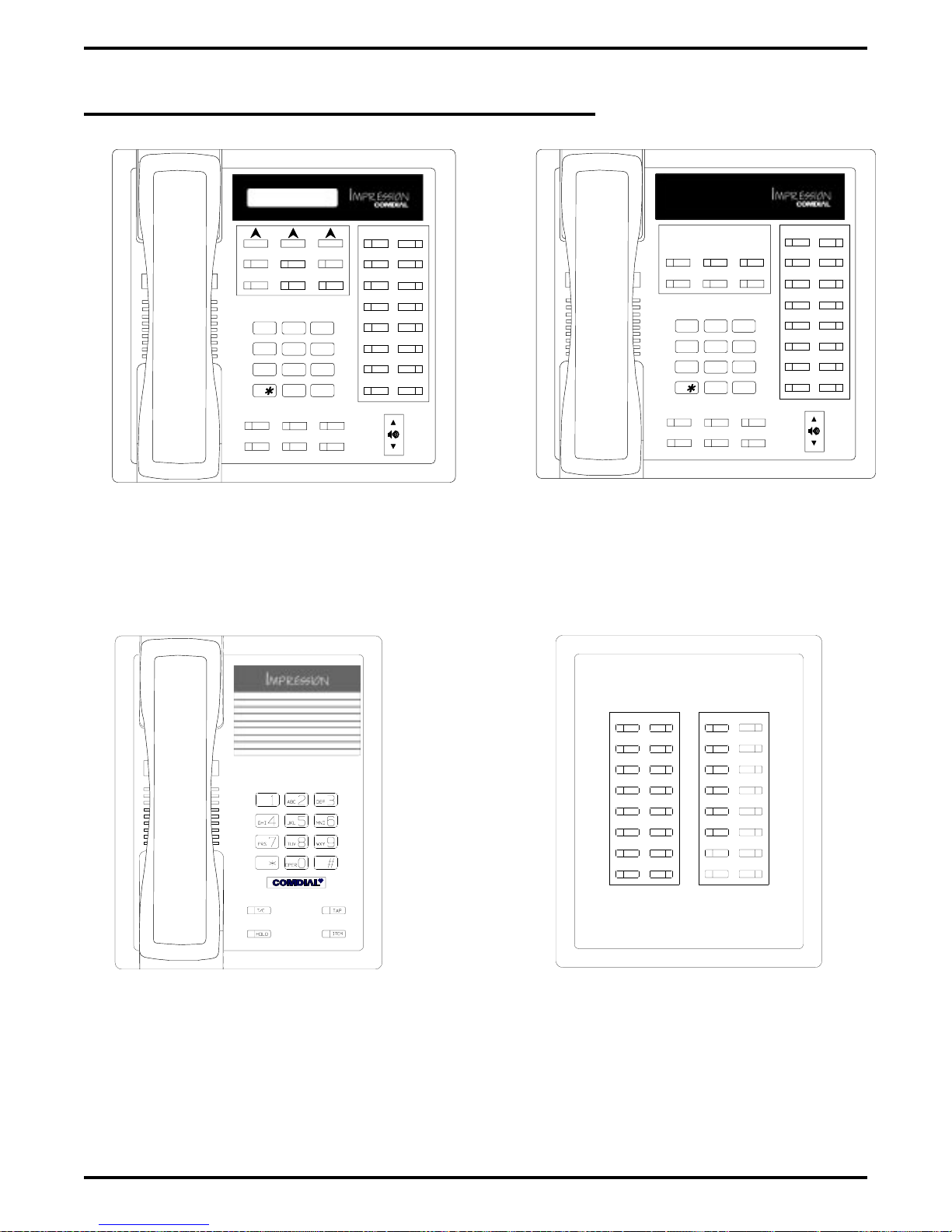
1.6.3 Impression Telephone Descriptions
1
ABC
DEF
3
GHI
PRS
SPKR
HOLD
1
ABC
JKL
4
TUV
708
OPER
3
DEF
2
MNO
6
5
WXY
9
#
T/C
MUTE
ITCM
TAP
GHI
PRS
SPKR
HOLD
JKL
4
TUV
708
OPER
2
MNO
6
5
WXY
9
#
T/C
MUTE
ITCM
TAP
2022S (22-Line LCD Speakerphone)
R
unisyn05.cdr
unisyn01.cdr
2122S (22-Line Speakerphone)
2122X (22-Line Monitor Telephone)
2101N (Single Line Proprietary Telephone)
1 – 14 Introducing The DSU
unisyn09.cdr
DU32X (32-Button DSS/BLF Console)
unisyn11.cdr
Figure 1–6: Impression Telephone Images
Page 19
IMI66–107 Digital Telephone System
8.90"
9.08"
4.78"
3.94"
UNIS029
1.13"
8.900
7.130
2101N
Figure 1–7: Impression Telephone Dimensions
cajs109
Introducing The DSU 1 – 15
Page 20
Digital Telephone System IMI66–107
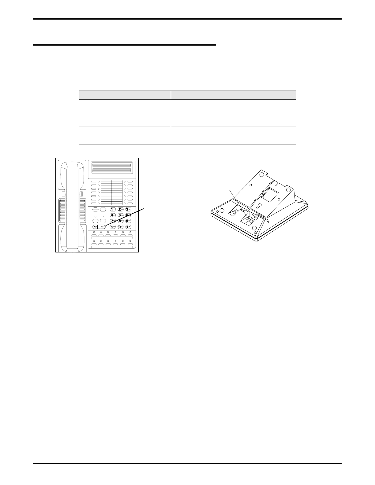
1.6.4 Station Controls And Indicators
Ringer Volume Control
Each station has a ringer volume control. Adjust the ringer volume of each station to suit your
needs.
Telephone Model Control Location
7114S, 7114X, 8024S,
8124S, 8012S, 8112S
7701X, 8101N, 8112N Switch on bottom housing. Set for
CAJS 75A
Rocker switch located on front face
plate. Adjust while ringing to set
volume.
fixed volume levels.
Display Intensity
You can adjust the intensity (brightness and contrast) of the display on LCD telephones any time
the telephone is idle and on-hook.
COMDIAL
TRANS
CONF
SPKR
HOLD ITCM
DIGITECH
Ringer VolumeSwitch
TAP
MUTE
Rocker Switch
CAJS096
Figure 1–8: Rocker Switch Locations on Typical Digital Telephones
To adjust the display intensity DigiTech and Impression telephones, press and hold the MUTE
button until the desired intensity is achieved. On Impact telephones, select DISP through the
interactive buttons.
1 – 16 Introducing The DSU
Page 21
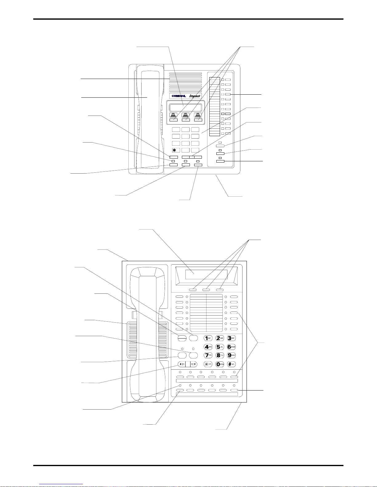
IMI66–107 Digital Telephone System
LCD Alphanumeric Display
Speaker
Handset
Transfer/
Conference
Button
Message
Waiting
Light
Hold
Button
TAP
Button
4
PRS WXY
TRNS/CNF
Intercom
Button
ABCQZ
5
TUV
87 9
OPER
0
TAPHOLD
Interactive Buttons
(NOT Programmable)
Progammable Buttons
Keypad
Volume Control
DEF
321
MNOJKLGHI
6
#
INTERCOM
SHIFT
MUTE
SPEAKER
Shift Button
Mute Button
Speaker Button
Microphone
Opening
CAJS107
LCD Alphanumeric Display
Auxiliary Jack
(On bottom)
TAP
Button
Transfer/
Conference
Button
Speaker
Mute
Button
Speaker
Button
Volume
Control
Message
Waiting
Light
Hold
Button
COMDIAL
TRANS
TAP
CONF
MUTE
SPKR
HOLD ITCM
Microphone
Opening
Interactive Buttons
(NOT Programmable)
DIGITECH
Programmable
Buttons
Intercom
Button
Figure 1–9: Station Controls And Indicators On
Impact
And DigiTech Telephones
Introducing The DSU 1 – 17
Page 22
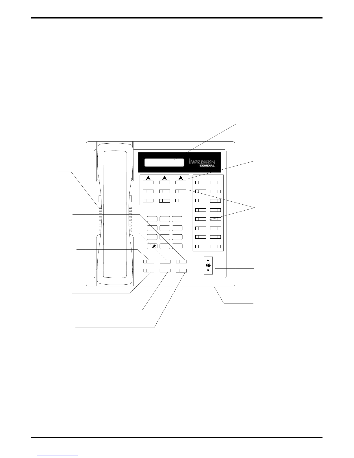
Digital Telephone System IMI66–107
LCD Display
Interactive Buttons
Speaker
Mute Button
T/C Button
SPKR Button
Message
Waiting Light
Hold Button
TAP Button
ITCM Button
GHI
PRS
SPKR
HOLD
1
ABC
JKL
4
TUV
708
OPER
Feature Buttons,
DEF
3
2
MNO
6
5
WXY
9
#
T/C
MUTE
ITCM
TAP
cajs110
Line Buttons, and
DSS Buttons
Volume Control
Microphone Opening
Figure 1–10:
Station Controls And Indicators On
1 – 18 Introducing The DSU
Impression Telephones
Page 23
IMI66–107 Digital Telephone System
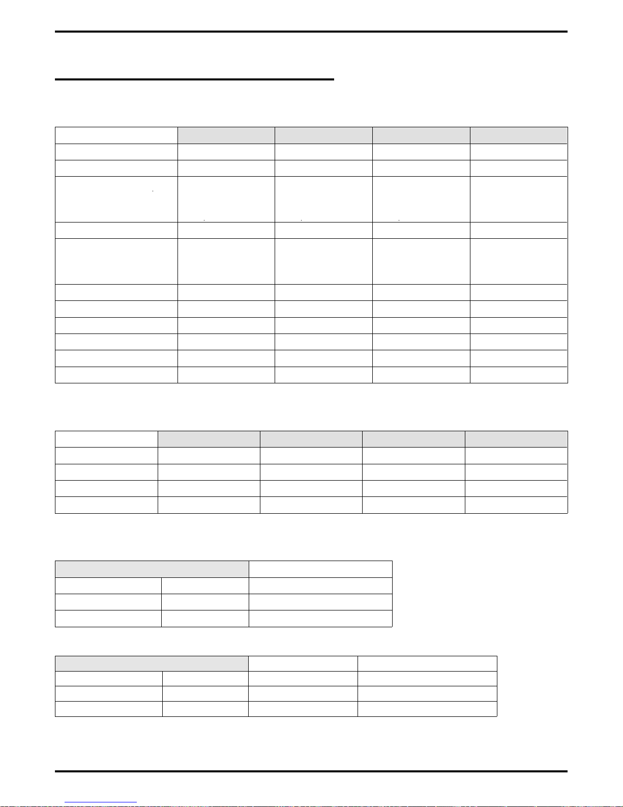
1.7 General Specifications
System Capacity
G0408 G0816 G1632 GM408
Lines 4 8 16 4
Stations 8 16 32 8
DSS/BLF Consoles
Intercom Paths Non-blocking Non-blocking Non-blocking Non-blocking
Maximum
Simultaneous
Intercom Conversations
Paging Ports 1 1 1 Not Applicable
Park Orbits 9 9 9 Not Applicable
System Speed Dials 99 99 99 Not Applicable
Station Speed Dials 10 10 10 Not Applicable
Autodials Unused Buttons Unused Buttons Unused Buttons Not Applicable
Power Fail Circuits 1111
Two Per Station
(One Per Station
Port)
Non-blocking Non-blocking Non-blocking Non-blocking
Two Per Station
(One Per Station
Port)
Two Per Station
(One Per Station
Port)
Two Per Station
(One Per Station
Port)
Common Equipment Dimensions
G0408 G0816 G1632 GM408
Width (inches) 16.5 16.5 16.5 16.5
Height (inches) 21.3 27.1 27.6 9.25
Depth (inches) 3.8 3.8 4.5 1.75
Weight (pounds) 17.5 26 30.5 4
Station Dimensions
DigiTech +
Multiline Single-Line Proprietary
Footprint (inches) 8.625 X 7.658 6.5 X 8.5
Weight (pounds) 2.5 1.9
Impact +
12-line 24-line Single-Line Proprietary
Footprint (inches) 9.08 X 8.9 10.75 X 8.9 8.9 X 7.13
Weight (pounds) 2.3 2.6 1.75
Introducing The DSU 1 – 19
Page 24
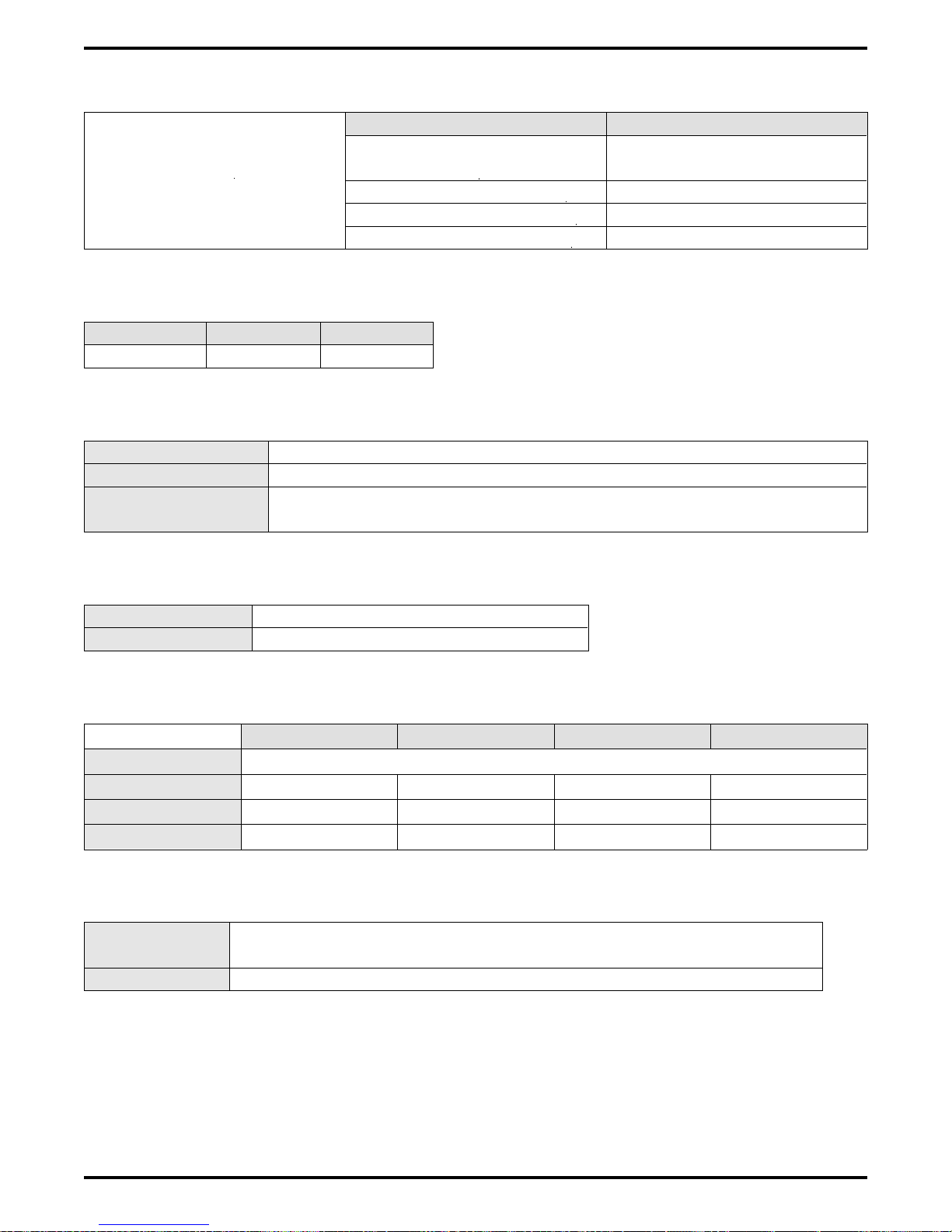
Digital Telephone System IMI66–107
Conferencing
G0408 and G0816 G1632
Maximum Combinations
at Any One Time
1 five-way plus 1 three-way
plus 2 SOHVA
2 four-way plus 2 SOHVA
1 four-way plus 3 three-way
5 three-way plus 1 SOHVA
4 five-way plus 1 three-way
plus 1 SOHVA
6 four-way plus 2 three-way
3 four-way plus 9 three-way
16 three-way
SMDA Storage Capacity
G0408 G0816 G1632
800 1600 1600
Station Cable Requirements
Type 2-wire (1-pair) twisted, non-shielded cable
Maximum Length 1000 feet with 24 gauge wire, 2000 feet with 22 gauge wire
Switching Principle
Digital, time division multiplexing (TDM). Provides non-blocking
switching with stored program control.
Operating Environment
Temperature 32-122 degrees F (0-50 degrees C)
Humidity 90 percent relative, non-condensing
Power Requirements
G0408 G0816 G1632 GM408
Voltage 90-129 VAC Single phase all models
Current 0.6A 2.0 A 2.1A Not Applicable
Power 70W 135W 150W Not Applicable
Volt/Amps 80VA 190VA 200VA Not Applicable
Terminations
Station Standard 50-pin male connectors for connection to external distribution
field
Line Standard 6-conductor mini-jack (USOC 14C)
1 – 20 Introducing The DSU
Page 25
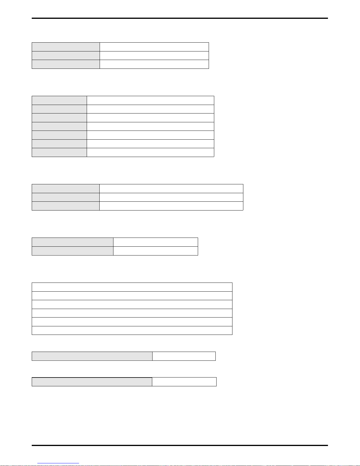
IMI66–107 Digital Telephone System
Music Interface
Input Level 3 Volts peak-to-peak maximum
Input Impedance Approximately 500 Ohms
Connector RCA phono jack
Station Message Detail Recording Port
Format Serial, pseudo RS-232C
Parity None
Data Bits 7 or 8 (programmable)
Stop Bits 1 or 2 (programmable)
Baud Rate Programmable in class of service
Handshaking X on -X off Hardware -CTS
Cable Length 500 feet maximum
PA Port
Output Level 400 Millivolts peak-to-peak (typical speech)
Output Impedance Approximately 500 Ohms
Connector RCA phono jack
Central Office Limits
Loop Limits 1900 Ohms maximum loop
Cable Insulation Leakage 15,000 Ohms minimum
Industry/Regulatory Standards
FCC Certified, part 15 (Class A)
FCC Registered (fully protected)
LISTED by OSHA-accredited, nationally recognized, test laboratory
EIA RS478
Bell publication 48002 guidance
Hearing aid compatible handset
Memory Retention After Power Loss 60 hours minimum
Ringer Equivalence Number 1.3B
Introducing The DSU 1 – 21
Page 26
Digital Telephone System IMI66–107
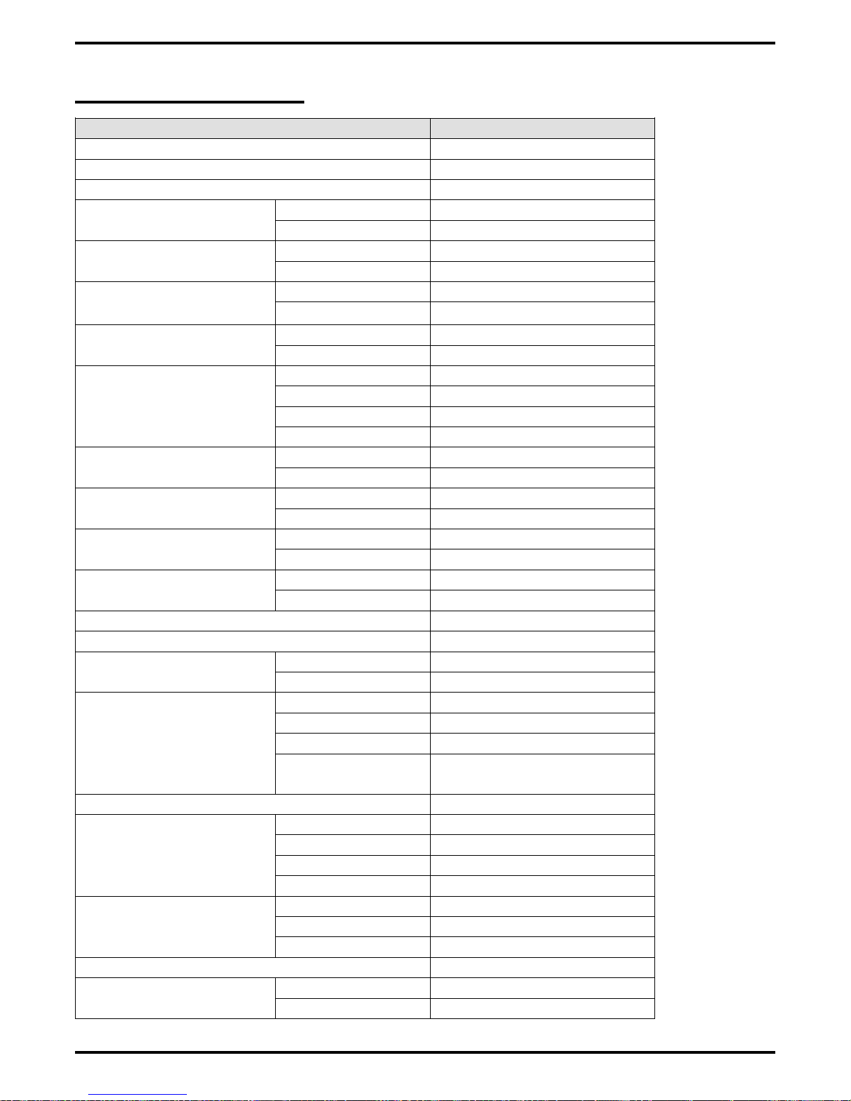
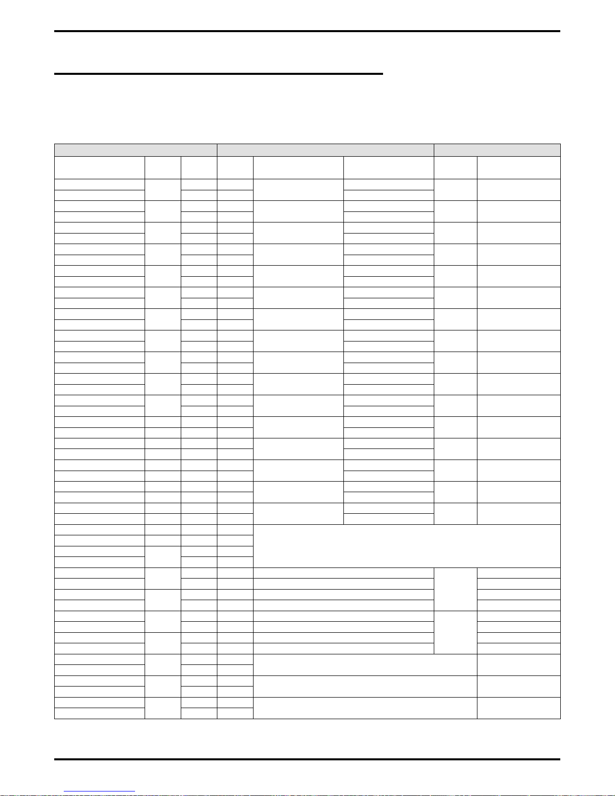
1.7.1 Feature Codes
Feature Dialing Code
All Call Page (Through Station Speakers) INTERCOM, 87
Attendant Calling INTERCOM, 0
Automatic Redialing Programmed Button
Background Music On INTERCOM, ✳ 1
Off INTERCOM, # 1
Automatic Call Back Activate INTERCOM, (ext no), ✳ 6
Cancel INTERCOM, # 6
Station-to-Station
Messaging
LCD Messaging Set INTERCOM, ✳ 02 (10)
Call Forward Personal INTERCOM, ✳ 05, (ext no)
Call Park Park Orbits 19 INTERCOM, ✳ (9199)
Call Pick Up Directed INTERCOM, ✳ 4, (ext no)
Call Waiting Tone Send INTERCOM, (ext no), ✳ 01
Do Not Disturb Set Programmed Button
Executive Override INTERCOM, (ext no), ✳ 03
External Page INTERCOM, 89
Handsfree Answer Inhibit Set MUTE
Hold Manual HOLD
Line Answer From Any Station INTERCOM, 80
Line Group Access Group 1 INTERCOM, 9
Line Queuing
Meet Me Answer Paging INTERCOM, 88
Message Waiting Set INTERCOM, ✳ 3, (ext no)
Activate INTERCOM, (ext no), ✳ 7
Cancel INTERCOM, # 7, (ext no)
Cancel INTERCOM, # 02
Cancel INTERCOM, # 05
All Calls INTERCOM, ✳ 5, (ext no)
Cancel INTERCOM, # 5
Pick Up INTERCOM, # (9199)
Group INTERCOM, # 4
Cancel Hang Up
Cancel Programmed Button
Cancel MUTE
Exclusive HOLD, HOLD
Direct INTERCOM, ✳ 90, (ext no)
Direct Hold Pick
INTERCOM, # 90
Up
Group 2 INTERCOM, 81
Group 3 INTERCOM, 82
Group 4 INTERCOM, 83
Enable Line Group INTERCOM, (gp code), ✳ 8
Cancel INTERCOM, # 8
Cancel From Idle INTERCOM, # 3, (ext no)
1 – 22 Introducing The DSU
Page 27

IMI66–107 Digital Telephone System
Cancel On Line INTERCOM,
Retrieve Message INTERCOM, HOLD
Night Transfer (Attendant) On INTERCOM, S # 03,
Programmed Button
Off INTERCOM, ✳ # 03,
Programmed Button
Personal Ringing Tones Set Tones 16 INTERCOM, ✳ ✳ 4 (16)
Pulse/Tone Switching #
Redial Last Dialed Number #
Save Number Redial Use HOLD, Programmed Button
Store Programmed Button
Service Observing INTERCOM, # 03, (ext no)
Speed Dial Station 09
System ✳ 0199
TAP (on line) Activate INTERCOM, #04
Toll Restriction Override Activate INTERCOM, ✳✳6 (extension
number, code)
Tracker Pager Enable INTERCOM, ✳06
Disable INTERCOM, #06
Send Message
INTERCOM, #01
Voice Announce Block Block INTERCOM, ✳ 2
Unblock INTERCOM, # 2
Zone Page Zone 1 INTERCOM, 84
Zone 2 INTERCOM, 85
Zone 3 INTERCOM, 86
Introducing The DSU 1 – 23
Page 28
Digital Telephone System IMI66–107
1.7.2 System Ringing Patterns
Ring Type Ring Cadence
CO/PBX Line Ring Host system ring cadence
Intercom Tone Signaling Two 150 msec. tone bursts every four seconds
Voice Signaling alert One 215 msec. tone burst
Timed hold recall at station that put call on hold Three 150 msec. tone bursts at the end of each
timeout period
Call back alert One 80 msec. tone burst followed by three 150
msec. tone bursts and one 80 msec. tone burst
Queue Enabled ^
Call forward alert One 80 msec. tone burst
Transfer ringing Two 1.1 sec tone busts every four seconds
Tone Type Tone Cadence
Dial Tone Continuous on
Called station ring-back One sec. on and three sec. off
Base level program entry 80 msec. tone burst sounded once
Error toneincorrect entry 530 msec. tone burst sounded three times
All-call and zone paging notification tone 80 msec. tone burst followed by 280 msec. tone
Busy tone 530 msec. tones sounded continuously
Override feature not allowed ^
Night transfer feature not allowed
Call waiting tone Three 80 msec. tone bursts sounded once
Called station in do-not-disturb mode
Call-back busy feature on 260 msec. tone burst sounded once
System is awaiting memory dial number or key
mapping entry after location is specified
Override feature on warning tone Six 100 msec. tone bursts sounded for 1.5 secs.
SOHVA tone ^
DISD ringback tone Dual 440/480 Hz tone sounded 1 sec. on/1 sec.
DISD dial tone 381 Hz tone sounded continuously
DISD confirmation tone Two 125 sec. bursts of 381 Hz tone sounded
DISD busy/error tone Three 500 msec. bursts of 381 Hz tone sounded
^
140 msec. tone burst sounded twice every 1.5
sec.
80 msec. tone burst sounded continuously
off
once
once
1 – 24 Introducing The DSU
Page 29

IMI66–107 Digital Telephone System
1.8 Seeking Repair Assistance
If your common equipment cabinet or individual stations need repair, you may return the
equipment to Comdial. Comdial will, at its option, either repair or replace it. There is a fixed
charge for this repair. For information on this charge, call or write to the address given below.
Comdial
P.O. Box 7266
Charlottesville VA 22906
Attn: Repair Department
Telephone: (804) 978-2400
1-800-877-4448
If you do return equipment for repair, pack it carefully to prevent damage. Any damages during
shipment are your responsibility. You should ship the equipment freight or postage prepaid.
Introducing The DSU 1 – 25
Page 30

Page 31

IMI66–107 Digital Telephone System
Installing The
Digital Telephone System
2
Section Title........................................................................................................... Page
2.1 Mounting Considerations..........................................................................2–4
2.1.1 Tools And Hardware ..............................................................................2–5
2.1.2 The Underwriters Laboratories Installation Notice................................2–5
2.1.3 Hybrid Installation..................................................................................2–5
2.2 Mounting The Cabinet...............................................................................2–6
2.3 Making The AC Power Connection .........................................................2–8
2.3.1 Identifying The Fuses.............................................................................2–8
2.3.2 Grounding The System.........................................................................2–10
2.4 Connecting The Lines..............................................................................2–12
2.4.1 Line Connection Details...................................................................... 2–14
2.4.2 Reassigning The Line Ports..................................................................2–14
2.4.3 Protecting The Lines.............................................................................2–14
2.5 Connecting The Stations..........................................................................2–16
2.5.1 Grounding The Stations........................................................................2–17
2.5.2 Relocating The Stations........................................................................2–17
2.5.3 Installing The Cable Clips....................................................................2–17
2.5.4 Connecting Stations To The G0408 .................................................... 2–19
2.5.5 Connecting Stations To The G0816 .................................................... 2–20
2.5.6 Connecting Stations To The G1632 .................................................... 2–21
2.5.7 Wall Mounting The Telephone Stations...............................................2–23
Installing The DSU 2 – 1
Page 32

Digital Telephone System IMI66–107
Section Title........................................................................................................... Page
2.6 Installing DSS/BLF Consoles..................................................................2–26
2.7 Connecting A Power Failure Station......................................................2–28
2.8 Using The Auxiliary Equipment Interface ............................................2–29
2.9 Common Audible And Auxiliary Ringing Interface.............................2–30
2.9.1 Connecting Outside Lines ....................................................................2–30
2.9.2 Connecting Selected Ports....................................................................2–30
2.10 Using The External Paging Interface.....................................................2–32
2.11 Using A Line Port As An External Paging Interface............................2–33
2.12 Connecting Data Devices.........................................................................2–34
2.12.1 Making Modular Jack Data Connections .............................................2–34
2.12.2 Making The Common Equipment Data Connections.......................... 2–36
2.12.3 Programming With A Video Display Terminal ...................................2–38
2.13 Using The Music Interface ......................................................................2–40
2.14 Using The Add-On Expansion Module..................................................2–41
2.14.1 Expansion Capabilities ........................................................................ 2–42
2.14.2 Connecting Stations To The Expansion Module................................. 2–43
2.14.3 Installing The Add-On Expansion Module ......................................... 2–44
2.15 Upgrading The System Software............................................................2–46
2.15.1 Creating A Static Safe Work Area .......................................................2–46
2.15.2 Saving The Call Cost Records..............................................................2–47
2.15.3 Replacing The Software Cartridge .......................................................2–48
2.15.4 Master Clearing The System ................................................................2–50
2 – 2 Installing The DSU
Page 33

IMI66–107 Digital Telephone System
Section Title........................................................................................................... Page
2.16 Checking The System Installation..........................................................2–51
2.16.1 Checking The Resistance......................................................................2–51
2.16.2 Checking The Voltage..........................................................................2–51
2.16.3 Checking The General Operating Conditions ..................................... 2–52
2.17 Isolating Failures......................................................................................2–53
2.17.1 Checking The System Status Indicator.................................................2–53
2.17.2 Testing The Stations.............................................................................2–53
2.18 Installing The System Options And Accessories.................................. 2–54
2.18.1 Installing The Battery Back Up Assembly.......................................... 2–54
2.18.2 Installing the Analog Terminal Interface............................................. 2–58
2.18.3 Installing the Data Interface Unit .........................................................2–68
2.19 Supporting Caller Identification Service ...............................................2–72
2.19.1 Setting The Caller ID Parameter Switches...........................................2–74
2.20 Supporting The Tracker Paging System................................................2–76
2.21 Supporting DVA Operation....................................................................2–78
2.22 FCC Rules And Regulations .................................................................. 2–80
Installing The DSU 2 – 3
Page 34

Digital Telephone System IMI66–107
2.1 Mounting Considerations
The following requirements will help you to install the digital telephone system.
Locate the equipment cabinet within four feet of an AC electrical outlet dedicated
•
exclusively to the use of this equipment. The outlet must be a 117 VAC 15 AMP circuit
with a third-wire ground supplied to a standard electrical outlet (NEMA 5–15R).
Mount the common equipment within 25 feet of the TELCO/PBX jacks. The recommended
•
nominal distance is 7 feet.
Choose a secure and dry mounting location that has adequate ventilation. The temperature
•
range of the location must be within 32-122 degrees F (0-50 degrees C) and that the relative
humidity is less than 90 percent, non-condensing.
If the mounting surface is damp or if it is made of concrete or masonry material, you must
•
attach a backboard to the mounting surface for mounting the common equipment. Suitable
mounting backboards are available commercially or you can construct one from 3/4-inch
plywood by cutting it to size.
2 – 4 Installing The DSU
Page 35

IMI66–107 Digital Telephone System
2.1.1 Tools And Hardware
You will need the following tools and materials to install the common equipment.
Fasteners—wood screws (1/4 x 1-inch round head), toggle bolts, or wall anchors,
•
Screwdriver—to match fasteners,
•
Electric drill—if prepared holes are required,
•
Connecting tool—for fastening wires to a type-66 connector block,
•
Crimping tool—for 623-type modular plugs,
•
Volt/Ohm Meter.
•
2.1.2 The Underwriters Laboratories Installation Notice
Per The Underwriters Laboratories standard 1459, 2nd edition, be aware of the following
precautions when installing telephone equipment that is to be directly connected to the telephone
company network:
Never install telephone wiring during a lightning storm,
•
Never install telephone jacks in wet locations unless the jack is specifically designed for
•
wet locations,
Never touch uninsulated telephone wires or terminals unless the telephone line has been
•
disconnected at the network interface,
Use caution when installing or modifying telephone lines.
•
2.1.3 Hybrid Installation
Whenever a programmer assigns lines to line groups, the digital telephone system automatically
assumes the hybrid mode. Your local telephone company may charge a higher monthly fee for
operation of a hybrid system; therefore, the FCC requires that you report the equipment-type
category designation number (KF for key system, MF for hybrid system) to the telephone
company at the time of installation.
FCC Registration Numbers
Key System CVWUSA-61535-KF-E
Hybrid System CVWUSA-61536-MF-E
Installing The DSU 2 – 5
Page 36

Digital Telephone System IMI66–107
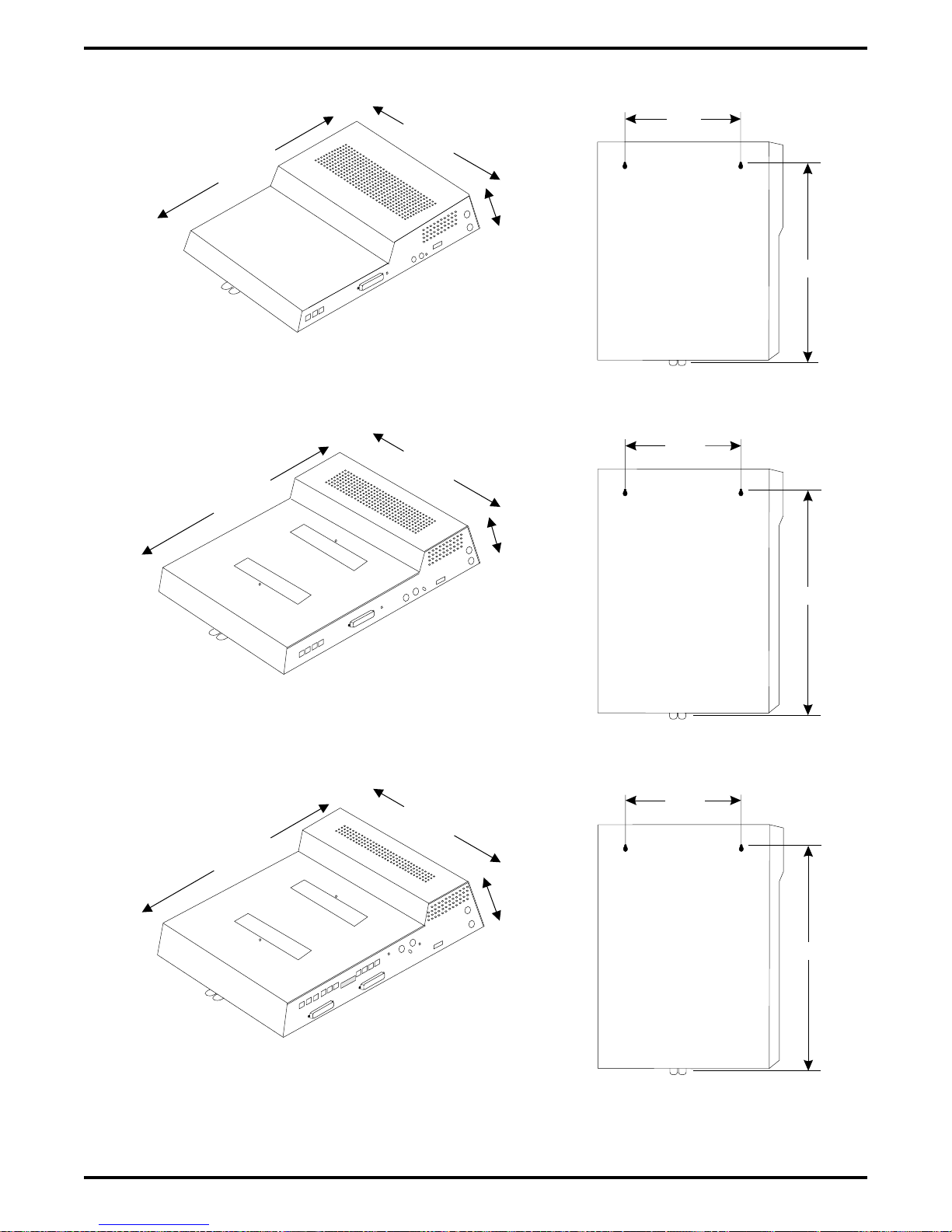
2.2 Mounting The Cabinet
After thoroughly reviewing Section 2.1 and fully understanding its subject matter, use the
following procedure to mount the common equipment cabinet
1. Unpack and carefully inspect all equipment for shipping damage. Notify the shipper
immediately of any damages that you find. Verify that the packages contain all parts and
accessories needed for proper installation and operation.
2. If the mounting location requires a backboard, attach it securely to provide a stable mounting
surface for the equipment.
3. Refer to Figure 2-1 or to the PP032-001 mounting template included in the literature that
accompanies the common equipment cabinet for the locating dimensions required for the
three mounting screws, and mark their locations on the mounting surface.
4. Drill holes in the mounting surface of a proper size to accommodate the hardware being
used. If necessary, prepare these holes with inserts, anchors or other attachment devices as
dictated by the type of mounting surface.
5. Insert the two top screws into the mounting surface and tighten them to within approximately
1/8-inch of the surface.
6. Hang the cabinet on the top screws using the mounting holes located on the rear of the
cabinet. Note that these holes are elongated with an enlargement at one end. This feature
allows the cabinet to snap down on the screws to secure the mounting when the cabinet is
hung on them.
7. Insert a third screw through the mounting tab located on the lower edge of the cabinet and
into the mounting surface, and tighten it into place.
8. Place the individual telephone stations as desired and in keeping with accepted industry and
office standards. You can wall mount a telephone station if necessary (see Section 2.5.7 for
details).
2 – 6 Installing The DSU
Page 37
IMI66–107 Digital Telephone System
0.87"
16.50"
21.30"
3.78"
Back of
4-Line, 8-Station
Base Unit
20.50"
4-Line, 8-Station Base Unit
0.88"
16.50"
27.58"
8-Line, 16-Station Base Unit
16.50"
27.58"
3.78"
4.54"
Back of
8-Line, 16-Station
Base Unit
0.88"
Back of
16-Line, 32-Station
Base Unit
26.25"
26.65"
16-Line, 32-Station Base Unit
CAJS044A
Figure 2–1: Cabinet Dimensions
Installing The DSU 2 – 7
Page 38
Digital Telephone System IMI66–107
2.3 Making The AC Power Connection
You must employ a dedicated 117VAC 15 AMP circuit, with a third-wire ground, supplied to a
standard electrical outlet (NEMA 5-15R) for the AC power connection.
For added equipment protection, connect a plug-in power line surge protector between the
•
power cord and the AC outlet.
Thoroughly check out the installation before connecting the power cord to an electrical
•
outlet to apply AC power to the system.
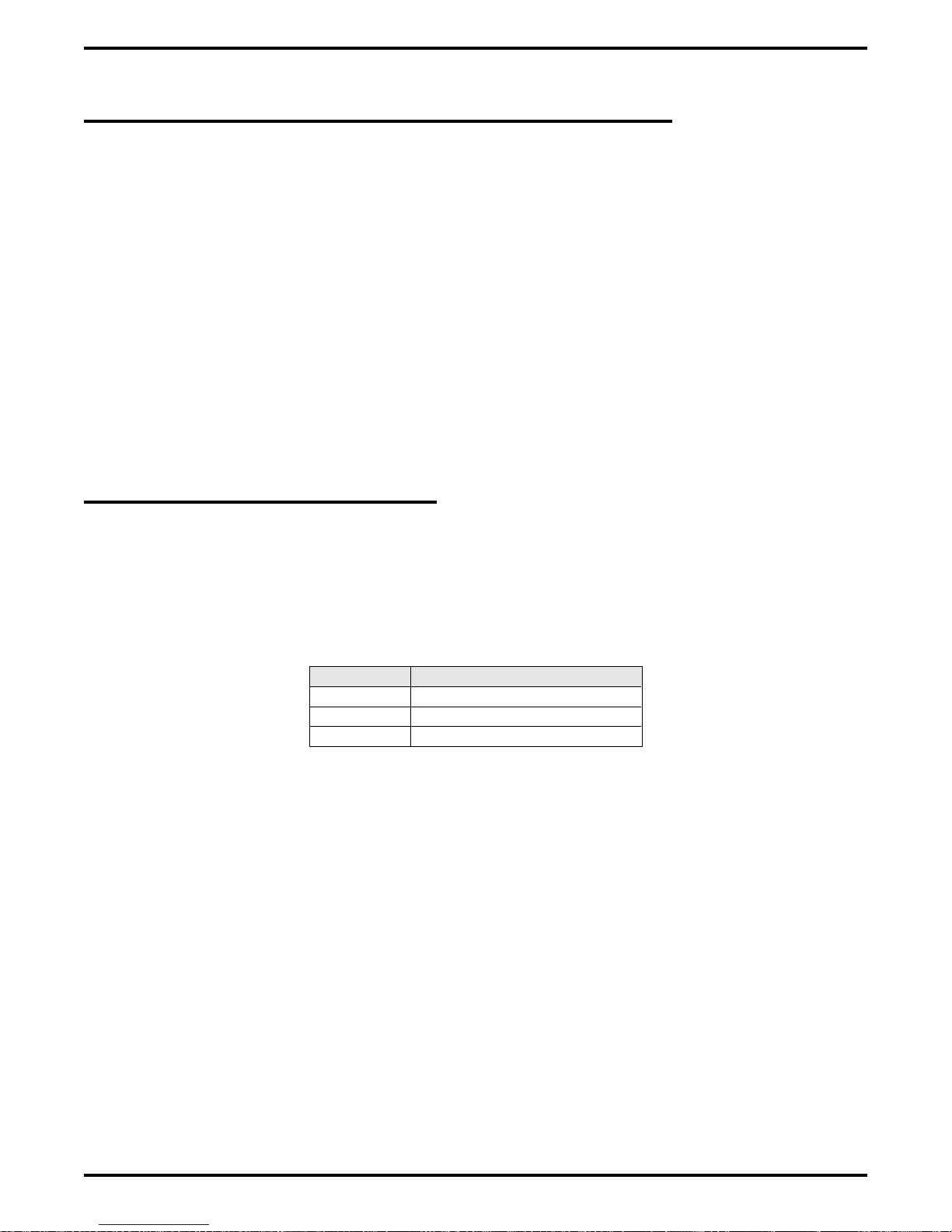
2.3.1 Identifying The Fuses
The system is protected against short circuit damage by a fuse located on the right side of the
common equipment cabinet. Always replace the fuse with one of the same value and type;
otherwise, equipment damage could result.
Table 2–1: Cabinets And Their Fuse Types
Cabinet Fuse Value
G0408 1A 250V slow-blow type
G0816 3A 250V slow-blow type
G1632 3A 250V slow-blow type
2 – 8 Installing The DSU
Page 39
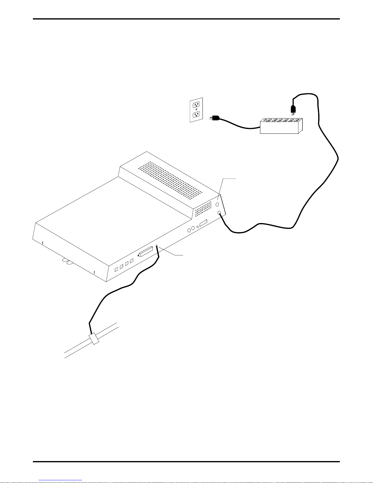
IMI66–107 Digital Telephone System
Dedicated 117VAC
15 AMP NEMA 5-15R
electrical outlet
with third-wire ground
Plug-in power
line surge
protector (typical)
CAJS079
Typical Common
Equipment
Fuse
(See text)
Grounding
terminal
Typical
earth
ground
Figure 2–2: Making The AC Power Connection
Installing The DSU 2 – 9
Page 40

Digital Telephone System IMI66–107
2.3.2 Grounding The System
If spare conductors exist in the cables between the station and the 66M-xx connector blocks, it is
good practice to connect them to an earth ground. Doing this may help prevent them from
inducing radio frequency and/or AC interference into the system. It is also good practice to
disconnect any unused station jacks from the connector block and ground that wiring to an earth
ground as well.
Transient voltage spikes, if induced onto CO or CENTREX lines, can travel through the cable
and into the common equipment. The telephone company offers basic protection against this
condition but it is usually designed to protect the central office circuits. While it will also
provide some protection to the common equipment, you should not rely upon it for total
protection. To help ensure that external over-voltage surges do not damage the system, you
should install and properly ground primary protection devices, such as gas discharge tubes or
similar devices, on all lines. While the line boards have internal secondary surge protection on
all line ports, in order for this protection to be effective, you MUST connect the common
equipment cabinet to a reliable, effective earth ground.
Proper DSU grounding is necessary for trouble-free operation and personnel safety. The DSU
has the following three types of grounds:
Service Ground—a neutral power line wire that is connected to the ground bus in the
•
premises’ AC power panel,
System Ground—a non-current carrying power line wire that is connected to the ground bus
•
in the premises’ AC power panel,
Frame Ground—a low impedance conductor that places the common equipment cabinet at
•
reference ground potential. The frame ground provides the greatest safety by limiting
electrical potential between non-current carrying parts of the system. The common
equipment cabinet provides a ground stud on its cabinet for access to its frame ground.
Effective grounding requires that you connect the frame ground to a good earth ground. A good
earth ground is one such as the ground bus in the premises’ AC power panel or a public metallic
cold water pipe at a point immediately at its entrance to the premises and ahead of any meters,
pumps, or insulating sections that have been added for vibration reduction. Avoid using the
premises’ structural steel frame as it may not be at earth ground potential. Make the ground
connection with #10 or #12 insulated, solid copper grounding wire. Keep the ground wire
separate from the three-wire AC line cord ground, do not splice it, and keep it as short as
possible.
The impedance of the wiring between the common equipment cabinet and the earth ground must
not exceed 0.25 ohms and the impedance between the earth ground and the power company’s
reference standard ground must not exceed 4 ohms. Use an acceptable low impedance measuring
device to measure the impedance of these paths. The #10 or #12 wire size will minimize the
wiring impedance; however, if the impedance between earth ground and the power company’s
standard reference ground exceeds 5 ohms, contact the local power company. The ground path
must always be of sufficient current-carrying capacity to prevent a build up of voltages that may
result in circuit noise, hazard to personnel, or equipment damage.
2 – 10 Installing The DSU
Page 41

IMI66–107 Digital Telephone System
Be sure that all of the ground connections are without splices and are visible for inspection and
maintenance. Tag all of the ground connections with a sign that reads: Do Not Remove Or
Disconnect.
If you install expansion modules on the base cabinet, attach at least a #10 or #12 insulated, solid
copper wire between the frame ground stud on the expansion module(s) to the frame ground stud
on the base cabinet.
Remember, if spare conductors exist in the cables that run between the stations and the 66M-xx
connector blocks, it is good practice to connect them to earth ground. Doing this may help
prevent them from introducing radio frequency and/or AC interference into the system. Also
remember that it is good practice to disconnect any unused station jacks from the connector
block and ground that wiring to earth ground as well.
Figure 2–3: Grounding The System
Installing The DSU 2 – 11
Page 42

Digital Telephone System IMI66–107
2.4 Connecting The Lines
The line terminations for the common equipment cabinet are standard modular plug/jack
connections. Line configuration must be loopstart only. Each modular jack provides termination
for two lines. Modular line jacks 1 and 2 also provide termination for an auxiliary pair in
addition to the two outside lines. The outside line termination can be a type 66M-xx connector
block or individual 6-position modular jacks. The line cord that is routed between the outside
line termination and the common equipment termination should be twisted-pair wiring. The
G0408, G0816 and G1632 common equipment supports the installation of up to 4, 8, or 16 lines,
respectively. Add-on expansion modules are available to expand the line capacity of the systems.
4-Line, 8-Station Base Unit
Lines 3 & 4, Aux. Line 4
Lines 1 & 2, Aux. Line 2
Grounding
Terminal
Line Jacks 1 & 2, Aux 1 (Line 2)
Line Jacks 3 & 4, Aux 2 (Line 4)
Line Jacks 5 & 6
Line Jacks 7 & 8
Line Jacks 9 & 10
Line Jacks 11 & 12
Line Jacks 13 & 14
Line Jacks 15 & 16
8-Line, 16-Station Base Unit
Grounding
Terminal
Line Jacks 1 & 2, Aux. Line 2
Line Jacks 3 & 4, Aux. Line 4
Line Jacks 5 & 6
Line Jacks 7 & 8
16-Line, 32-Station Base Unit
CAJS082
2 – 12 Installing The DSU
Grounding
Terminal
Figure 2–4: Locating The Line Connections
Page 43

IMI66–107 Digital Telephone System
(Typical 8-Line, 16-Station
Base Unit Shown)
6-Wire Twisted
Pair Cable
{
{
{
RING 2
RING 1
TIP 1
TIP 2
RING 4
RING 3
TIP 3
TIP 4
RING 6
RING 5
TIP 5
TIP 6
CO/PBX
LINES
Aux. Ring
Ring 2
Ring 1
Tip 1
Tip 2
Aux. Tip
Pin designation for
Line Jacks 1 and 2
RING 8
RING 7
{
Line Terminations
Type 66M-XX
Connector Block
or
Individual 6-Position
Modular jacks
No Conn.
6
5
4
3
2
1
Ring 2
Ring 1
Tip 1
Tip 2
6
5
4
3
2
1
TIP 7
TIP 8
CAJS083
No. Conn.
Pin designation for
Line Jacks 5 and 6
Figure 2–5: Detailing The CO Line Interface
Installing The DSU 2 – 13
Page 44

Digital Telephone System IMI66–107
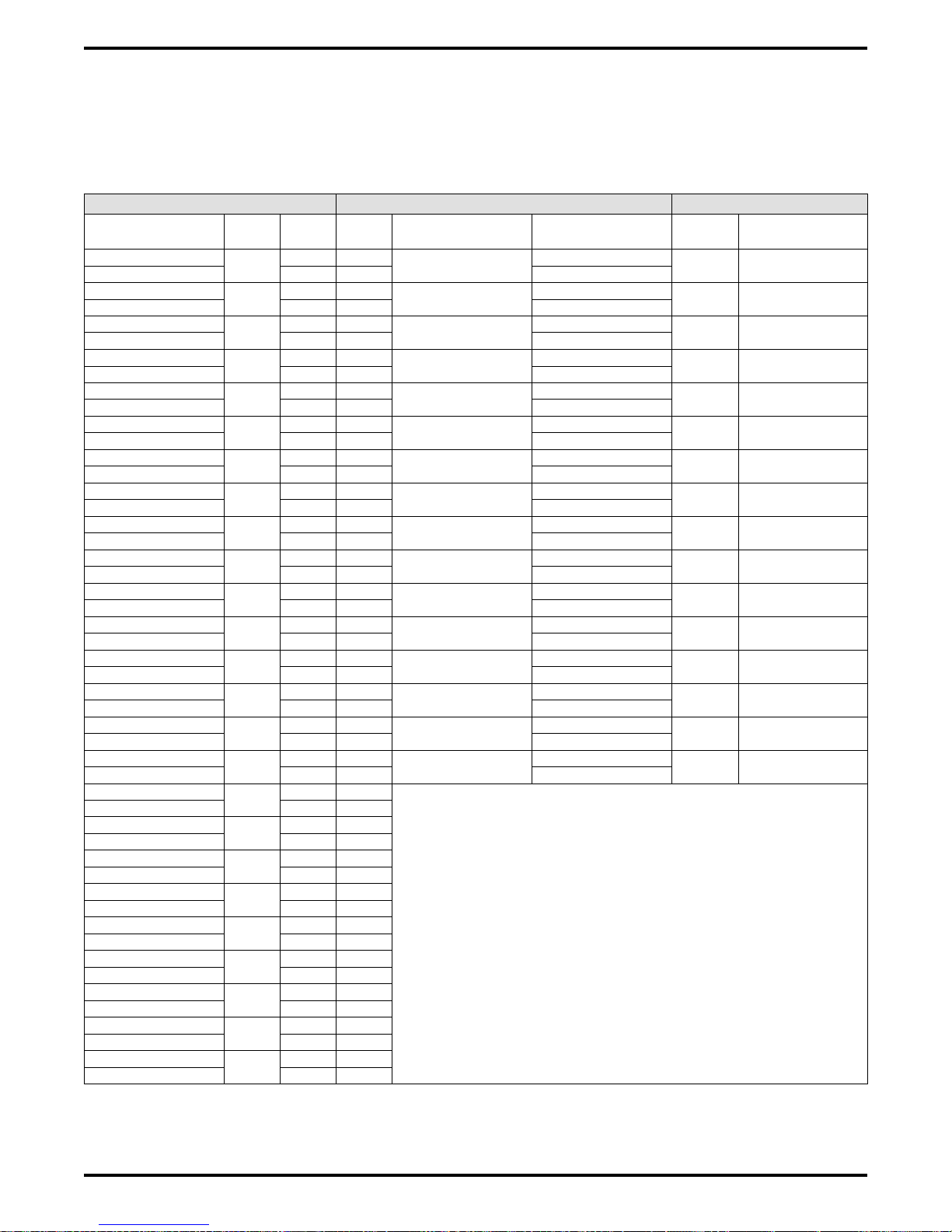
2.4.1 Line Connection Details
The table on the next page shows the line connection details for all three of the common
equipment base units. Jacks one and two are the same for all three cabinets, jacks three and four
are the same for both the G0816 and G1632 cabinets, and jacks five through eight are only
available on the G1632 cabinet.
2.4.2 Reassigning The Line Ports
After you have initially connected a line to a particular line port and programmed its attributes
(or left it with the system defaulted values), you can reassign the line and its attributes to a
different port by programming action if you wish. This feature allows you to make adds, moves,
and changes without relocating the line wiring. Refer to Chapter 3 for the line to line port
reassignment programming details.
2.4.3 Protecting The Lines
Transient voltage spikes, if induced onto CO or CENTREX lines, can travel through the cable
and into the common equipment. The telephone company offers basic protection against this
condition but it is usually designed to protect the central office circuits. While it will also
provide some protection to the common equipment, it should not be relied upon for total
protection. To help ensure that external over-voltage surges do not damage the system, the
manufacturer recommends that gas discharge tubes, or similar primary protection devices, be
installed and properly grounded on all lines (a selection of solid-state protection devices that are
useful for this purpose is available from ITW Linx, Elk Grove Village, Illinois 60007).
2 – 14 Installing The DSU
Page 45

IMI66–107 Digital Telephone System
Table 2–2: Understanding the Line Connection Details
Common Equipment Type Line Jack Pin No. Connection Telephone Number
1 Auxiliary 1 (Line 2) Tip
2 Line 2 Tip
3 Line 1 Tip
4 Line 1 Ring
5 Line 2 Ring
6 Auxiliary 1 (Line 2) Ring
1 Auxiliary 2 (Line 4) Tip
2 Line 4 Tip
3 Line 3 Tip
4 Line 3 Ring
5 Line 4 Ring
6 Auxiliary 2 (Line 4) Ring
1 No Connection
2 Line 6 Tip
3 Line 5 Tip
4 Line 5 Ring
5 Line 6 Ring
6 No Connection
1 No Connection
2 Line 8 Tip
3 Line 7 Tip
4 Line 7 Ring
5 Line 8 Ring
6 No Connection
1 No Connection
2 Line 10 Tip
3 Line 9 Tip
4 Line 9 Ring
5 Line 10 Ring
6 No Connection
1 No Connection
2 Line 12 Tip
3 Line 11 Tip
4 Line 11 Ring
5 Line 12 Ring
6 No Connection
1 No Connection
2 Line 14 Tip
3 Line 13 Tip
4 Line 13 Ring
5 Line 14 Ring
6 No Connection
1 No Connection
2 Line 16 Tip
3 Line 15 Tip
4 Line 15 Ring
5 Line 16 Ring
6 No Connection
G0408,
G0816,
and
G1632
G0816
and
G1632
G1632
1
2
3
4
5
6
7
8
Installing The DSU 2 – 15
Page 46

Digital Telephone System IMI66–107
2.5 Connecting The Stations
The digital telephone system supports the operation of proprietary Comdial telephones.
The G0408, G0816 and G1632 common equipment supports the installation of up to eight, 16,
or 32 telephones, respectively. Add-on expansion modules are available to expand the station
capacity of the systems. One 4-line 8-station expansion module can be added to the G0408. The
G0816 and G1632 can each take two expansion modules.
Connections between the common equipment and the stations are typically via type 66M-xx
connector blocks which are cable connected to the common equipment’s 50–pin male connector.
The connector block is, in turn, wired to modular jacks that accept the modular line cord
connected between it and the telephones.
The maximum distance allowed from the common equipment to the stations is per the following
list:
Multiline Telephones—1000 feet using #24 gauge, twisted-pair cable or 2000 feet using
•
#22 gauge cable
When installing the system telephones keep in mind that each station port supports only one
proprietary telephone and the system does not allow you to bridge two stations to a single
modular jack.
Always route station wiring a minimum of 12 inches from any other parallel wires or electrical
devices. If electrical noise or RF energy is at a high level, this may require the use of shielded
cable with the shield connected to the cabinet ground lug.
2 – 16 Installing The DSU
Page 47

IMI66–107 Digital Telephone System
2.5.1 Grounding The Stations
Remember, if spare conductors exist in the cables that run between the stations and the 66M-xx
connector blocks, it is good practice to connect them to earth ground. Doing this may help
prevent them from introducing radio frequency and/or AC interference into the system. Also
remember that it is good practice to disconnect any unused station jacks from the connector
block and ground that wiring to earth ground as well.
Remove insulation and twist together all spare wires at the wall outlet. Ground the wires at the
66M-xx to the common equipment cabinet ground lug.
2.5.2 Relocating The Stations
The Comdial proprietary telephones identify themselves to the system when you install them.
The system assigns an extension number and all other programmable attributes to station ports as
a default that you can reprogram as needed. Plus, you can use programming action to reassign
attributes of one station port to a different station port if you wish. This station relocation feature
allows you to do adds, moves, and changes without relocating the station wiring. Refer to the
automatic station relocation programming procedure and the station-to-station programming
procedure found in Chapter 3.
NOTE: The system will not allow you to relocate the station 10 to station port 10 assignment.
2.5.3 Installing The Cable Clips
Each cabinet-mounted 50-pin male connector is equipped with a retaining clip. This clip is
designed to secure the mated connection once it is made. The clip does this by snapping into a
slot on the cable-mounted connector when it is pressed together with the cabinet-mounted
connector. This retaining clip must be pulled back slightly to unsnap it before the connectors can
be separated.
Installing The DSU 2 – 17
Page 48

Digital Telephone System IMI66–107
4-Line, 8-Station Base Unit
Station 10-17,
Power Fail Station
Grounding
Terminal
Stations 10-25
Stations 26-41
8-Line, 16-Station Base Unit
Grounding
Terminal
Station 10-25
Power Fail Station
16-Line, 32-Station Base Unit
Power Fail Station
CAJS084
2 – 18 Installing The DSU
Grounding
Terminal
Figure 2–6: Station Connections
Page 49

IMI66–107 Digital Telephone System
2.5.4 Connecting Stations To The G0408
This table shows the color-coded connections for a G0408 common equipment cabinet.
Table 2–3: Connecting Stations To The G0408 Common Equipment Cabinet
25-Pair Connections Two-Wire Connections Station Connections
Wire Color Pair Pin No.
White-Blue
Blue-White 1 2 Red
White-Orange
Orange-White 2 4 Red
White-Green
Green-White 3 6 Red
White-Brown
Brown-White 4 8 Red
White-Slate
Slate-White 5 10 Red
Red-Blue
Blue-Red 6 12 Red
Red-Orange
Orange-Red 7 14 Red
Red-Green
Green-Red 8 16 Red
Red-Brown
Brown-Red 9 18
Red-Slate
Slate-Red 10 20
Black-Blue
Blue-Black 11 22
Black-Orange
Orange-Black 12 24
Black-Green
Green-Black 13 26
Black-Brown
Brown-Black 14 28
Black-Slate
Slate-Black 15 30
Yellow-Blue
Blue-Yellow 16 32
Yellow-Orange
Orange-Yellow 17 34
Yellow-Green
Green-Yellow 18 36
Yellow-Brown
Brown-Yellow 19 38 RD
Yellow-Slate
Slate-Yellow 20 40 SG
Violet-Blue
Blue-Violet 21 42 RD
Violet-Orange
Orange-Violet 22 44 SG
Violet-Green
Green-Violet 23 46
Violet-Brown
Brown-Violet 24 48
Violet-Slate
Slate-Violet 25 50
26 1
1
27 3
2
28 5
3
29 7
4
30 9
5
31 11
6
32 13
7
33 15
8
34 17
9
35 19
10
36 21
11
37 23
12
38 25
13
39 27
14
40 29
15
41 31
16
42 33
17
43 35
18
44 37
19
45 39 CTS
20
46 41
21
47 43 CTS
22
48 45
23
49 47
24
50 49
25
Clip
Term.
Pair Wire Color Station Location
Signal Path
Signal Path
Signal Path
Signal Path
Signal Path
Signal Path
Signal Path
Signal Path
Green
Green
Green
Green
Green
Green
Green
Green
Spare Pairs
10
11
12
13
14
15
16
17
RS232
Data Port
A
RS232
Data Port
B
TD
TD
Common Audible
Station 17 Audible
Power Fail Station
Installing The DSU 2 – 19
Page 50
Digital Telephone System IMI66–107
2.5.5 Connecting Stations To The G0816
This table shows the color-coded connections for a G0816 common equipment cabinet.
Table 2–4: Connecting Stations To The G0816 Common Equipment Cabinet
25-Pair Connections Two-Wire Connections Station Connections
Wire Color Pair Pin No.
White-Blue
Blue-White 1 2 Red
White-Orange
Orange-White 2 4 Red
White-Green
Green-White 3 6 Red
White-Brown
Brown-White 4 8 Red
White-Slate
Slate-White 5 10 Red
Red-Blue
Blue-Red 6 12 Red
Red-Orange
Orange-Red 7 14 Red
Red-Green
Green-Red 8 16 Red
Red-Brown
Brown-Red 9 18 Red
Red-Slate
Slate-Red 10 20 Red
Black-Blue
Blue-Black 11 22 Red
Black-Orange 12 37 23
Orange-Black 12 24 Red
Black-Green 13 38 25
Green-Black 13 26 Red
Black-Brown 14 39 27
Brown-Black 14 28 Red
Black-Slate 15 40 29
Slate-Black 15 30 Red
Yellow-Blue 16 41 31
Blue-Yellow 16 32 Red
Yellow-Orange 17 42 33
Orange-Yellow 17 34
Yellow-Green
Green-Yellow 18 36
Yellow-Brown
Brown-Yellow 19 38 RD
Yellow-Slate
Slate-Yellow 20 40 SG
Violet-Blue
Blue-Violet 21 42 RD
Violet-Orange
Orange-Violet 22 44 SG
Violet-Green
Green-Violet 23 46
Violet-Brown
Brown-Violet 24 48
Violet-Slate
Slate-Violet 25 50
1
2
3
4
5
6
7
8
9
10
11
18
19
20
21
22
23
24
25
26 1
27 3
28 5
29 7
30 9
31 11
32 13
33 15
34 17
35 19
36 21
43 35
44 37
45 39 CTS
46 41
47 43 CTS
48 45
49 47
50 49
Clip
Term.
Pair Wire Color Station Location
Signal Path
Signal Path
Signal Path
Signal Path
Signal Path
Signal Path
Signal Path
Signal Path
Signal Path
Signal Path
Signal Path
Signal Path
Signal Path
Signal Path
Signal Path
Signal Path
Green
Green
Green
Green
Green
Green
Green
Green
Green
Green
Green
Green
Green
Green
Green
Green
10
11
12
13
14
15
16
17
18
19
20
21
22
23
24
25
RS232
Data
Port A
RS232
Data
Port B
TD
TD
Common Audible
Station 17 Audible
Power Fail Station
2 – 20 Installing The DSU
Page 51

IMI66–107 Digital Telephone System
2.5.6 Connecting Stations To The G1632
The following two tables show the color-coded connections for a G1632 common equipment
cabinet.
Table 2–5: Connecting Stations To J1 On The G1632 Common Equipment Cabinet
25-Pair Connections Two-Wire Connections Station Connections
Wire Color Pair Pin No.
White-Blue
Blue-White 1 2 Red
White-Orange
Orange-White 2 4 Red
White-Green
Green-White 3 6 Red
White-Brown
Brown-White 4 8 Red
White-Slate
Slate-White 5 10 Red
Red-Blue
Blue-Red 6 12 Red
Red-Orange
Orange-Red 7 14 Red
Red-Green
Green-Red 8 16 Red
Red-Brown
Brown-Red 9 18 Red
Red-Slate
Slate-Red 10 20 Red
Black-Blue
Blue-Black 11 22 Red
Black-Orange
Orange-Black 12 24 Red
Black-Green
Green-Black 13 26 Red
Black-Brown
Brown-Black 14 28 Red
Black-Slate
Slate-Black 15 30 Red
Yellow-Blue
Blue-Yellow 16 32 Red
Yellow-Orange
Orange-Yellow 17 34
Yellow-Green
Green-Yellow 18 36
Yellow-Brown
Brown-Yellow 19 38
Yellow-Slate
Slate-Yellow 20 40
Violet-Blue
Blue-Violet 21 42
Violet-Orange
Orange-Violet 22 44
Violet-Green
Green-Violet 23 46
Violet-Brown
Brown-Violet 24 48
Violet-Slate
Slate-Violet 25 50
1
2
3
4
5
6
7
8
9
10
11
12
13
14
15
16
17
18
19
20
21
22
23
24
25
26 1
27 3
28 5
29 7
30 9
31 11
32 13
33 15
34 17
35 19
36 21
37 23
38 25
39 27
40 29
41 31
42 33
43 35
44 37
45 39
46 41
47 43
48 45
49 47
50 49
Clip
Term.
Pair Wire Color Station Location
Signal Path
Signal Path
Signal Path
Signal Path
Signal Path
Signal Path
Signal Path
Signal Path
Signal Path
Signal Path
Signal Path
Signal Path
Signal Path
Signal Path
Signal Path
Signal Path
Green
Green
Green
Green
Green
Green
Green
Green
Green
Green
Green
Green
Green
Green
Green
Green
10
11
12
13
14
15
16
17
18
19
20
21
22
23
24
25
Installing The DSU 2 – 21
Page 52
Digital Telephone System IMI66–107
Table 2–6: Connecting Stations To J2 On The G1632 Common Equipment Cabinet
25-Pair Connections Two-Wire Connections Station Connections
Wire Color Pair Pin No.
White-Blue
Blue-White 1 2 Red
White-Orange
Orange-White 2 4 Red
White-Green
Green-White 3 6 Red
White-Brown
Brown-White 4 8 Red
White-Slate
Slate-White 5 10 Red
Red-Blue
Blue-Red 6 12 Red
Red-Orange
Orange-Red 7 14 Red
Red-Green
Green-Red 8 16 Red
Red-Brown
Brown-Red 9 18 Red
Red-Slate
Slate-Red 10 20 Red
Black-Blue
Blue-Black 11 22 Red
Black-Orange
Orange-Black 12 24 Red
Black-Green
Green-Black 13 26 Red
Black-Brown
Brown-Black 14 28 Red
Black-Slate
Slate-Black 15 30 Red
Yellow-Blue
Blue-Yellow 16 32 Red
Yellow-Orange
Orange-Yellow 17 34
Yellow-Green
Green-Yellow 18 36
Yellow-Brown
Brown-Yellow 19 38
Yellow-Slate
Slate-Yellow 20 40
Violet-Blue
Blue-Violet 21 42
Violet-Orange
Orange-Violet 22 44
Violet-Green
Green-Violet 23 46
Violet-Brown
Brown-Violet 24 48
Violet-Slate
Slate-Violet 25 50
1
2
3
4
5
6
7
8
9
10
11
12
13
14
15
16
17
18
19
20
21
22
23
24
25
26 1
27 3
28 5
29 7
30 9
31 11
32 13
33 15
34 17
35 19
36 21
37 23
38 25
39 27
40 29
41 31
42 33
43 35
44 37
45 39
46 41
47 43
48 45
49 47
50 49
Clip
Term.
Pair Wire Color Station Location
Signal Path
Signal Path
Signal Path
Signal Path
Signal Path
Signal Path
Signal Path
Signal Path
Signal Path
Signal Path
Signal Path
Signal Path
Signal Path
Signal Path
Signal Path
Signal Path
Green
Green
Green
Green
Green
Green
Green
Green
Green
Green
Green
Green
Green
Green
Green
Green
26
27
28
29
30
31
32
33
34
35
36
37
38
39
40
41
2 – 22 Installing The DSU
Page 53

IMI66–107 Digital Telephone System
2.5.7 Wall Mounting The Telephone Stations
The DigiTech (product code 77nnn), Impact (product code 8nnnn), and Impression (product
code 2nnnn) telephones are shipped from the factory configured for desk use. To convert them
for wall-mounting, follow the procedures outlined below.
To convert the DigiTech model 77nnn telephones for wall-mounting,
1. Disconnect line cord and handset cord from telephone.
2. Turn telephone over to expose lower housing.
CAUTION
The telephone circuitry is sensitive to static electricity discharge. Be sure that your body and
the workplace are properly grounded to avoid any static electricity discharge while you
perform step 3.
3. Remove screws that attach lower housing to
upper housing. Carefully serparate lower and
upper housings making sure not to disconnect
wiring between them.
4. Rotate lower housing 180 degrees. Do not
disturb any internal wiring.
5. Refasten lower housing to upper housing.
Make sure no wires are caught between upper
and lower housings. Do not over-tighten
screws wile refastening the housings.
6. Route line cord through appropriate channel
on lower housing, and reconnect it to
telephone. You may substitute a shorter line
cord if you wish.
7. Reconnect the handset cord.
Figure 2–7: Rotating The Lower
Housing On Model 77nnn
Telephones
Installing The DSU 2 – 23
Page 54
Digital Telephone System IMI66–107
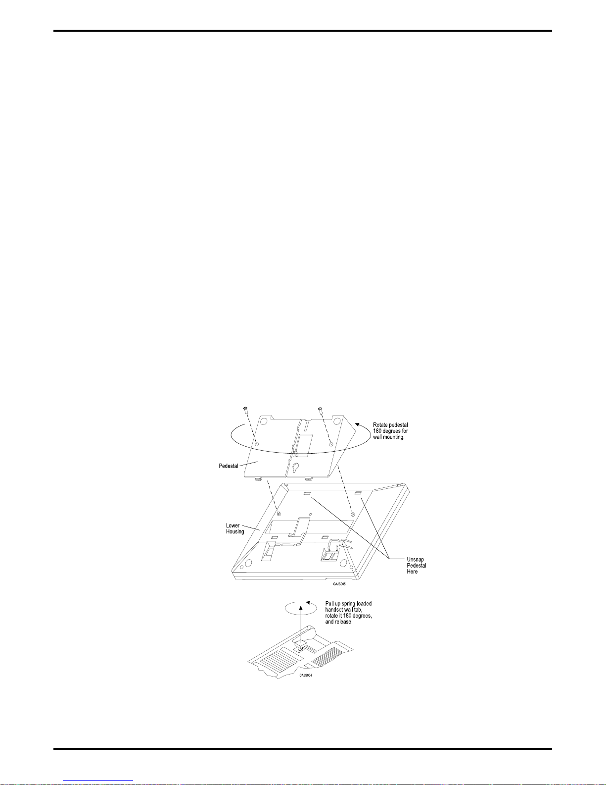
To convert the model Impact (models 80nnn and 81nnn) and Impression (models
20nn and 21nnn) telephones for wall-mounting,
1. Turn telephone over and disconnect line cord and handset cord from telephone. Do not
damage line cord on plastic dressing tabs.
2. Remove screws from pedestal and unlatch it from telephone housing, rotate it 180 degrees,
relatch its tabs in the slots in the lower housing of the telephone, and replace screws.
3. Route line cord as appropriate, and reconnect it to telephone. Substitute shorter line cord if
desired.
4. This telephone has a reversible handset retaining hook. When wall mounting, pull up this
hook and rotate it 180 degrees (see Figure 2–8).
5. Reconnect the handset cord.
There are wall-mounting enhancement kits available through your normal distribution channels.
These kits include a handset cradle cup that you can screw-mount to the telephone’s upper
housing. The product codes for these enhancement kits are: HCCI for the Impact telephones
(models 80nnn and 81nnn) and Impression telephones (models 20nnn and 21nnn), and HCCX
for the DigiTech telephones (model 77nnn).
Figure 2–8: Reversing The Pedestal And Handset Hook
Impact
On
2 – 24 Installing The DSU
(models 80nnn and 81nnn) and Impression
(models 20nnn and 21nnn) Telephones
Page 55

IMI66–107 Digital Telephone System
To wall-mount the telephones,
After configuring a telephone for wall mounting, either mount it directly on the wall using two
#10 panhead screws (obtained locally), or mount it on a wall jack cover plate. If using a wall
jack cover plate, use an AT&T type 630B wall plate for best results.
1. If #10 screws are used, thread them into the wall within 1/8-inch of the surface. Refer to
Figure 2–9 for the spacing dimensions.
2. Position the keyhole-shaped holes in the bottom of the telephone over the #10 screws or the
cover plate studs. Slide the telephone down until a slight click is felt.
3. To remove the telephone, lift to unsnap both screws or studs from the bottom housing, and
then lift away from the wall.
Figure 2–9: Station Wall Mounting
Details
Installing The DSU 2 – 25
Page 56

Digital Telephone System IMI66–107
2.6 Installing DSS/BLF Consoles
The digital telephone system supports the installation and use of a DigiTech DD32X or Impact
IB64X consoles at any available station port. The number of installed consoles is limited only by
port availability; however, since a console complements a companion telephone located in an
adjacent station port, you can use up to one-half of the available station ports for consoles. In
addition, with the dual console feature (discussed later), a full two-thirds of the total station port
capacity is available for console use.
You can assign two consoles to one telephone, each taking its own station port. This feature is
especially useful with DigiTech DD32X consoles and a G1632 system that has one or two
GM408 expansion modules included with it. This dual console feature allows a station user to
monitor up to 48 stations from one station location using 32-button consoles.
Install the first console at the station port that is logic-paired with the station that you wish to
complement. Install the second console at any station port except 10 or 11 and, using class of
service programming, assign it to the same station port that is logic-paired with the first console.
Table 2–7: Pairing Of Digital Station Ports
10–11 26–27 42–43
12–13 28–29 44–45
14–15 30–31 46–47
16–17 32–33 48–49
18–19 34–35 50–51
20–21 36–37 52–53
22–23 38–39 54–55
24–25 40–41 56–57
You can install the DSS/BLF console at any station port and assign it to a station without first
installing a console at the station’s logic-paired port if you wish. This configuration is
convenient for adding a console to an existing telephone installation that already has its
logic-paired port occupied; however, do not use this configuration for assigning a console to
station ports 10 and 12 because the console buttons will not be usable for programming. As
discussed above, this feature is also useful for adding a second console to a station that already
has a paired console installed with it.
The digital telephone system automatically recognizes a console when you connect it to a station
port and automatically assigns the station intercom numbers to the console buttons for direct
station selection (DSS) purposes with associated busy lamp field (BLF) status lights. However,
the console buttons are fully programmable and the station user can customize them as he or she
sees fit by programming them as DSS buttons or as automatic dialing (autodial) buttons. When
the user programs the buttons for DSS use, autodial capability is also available at a secondary
level at each DSS button.
2 – 26 Installing The DSU
Page 57

IMI66–107 Digital Telephone System
While the first console (the one installed at the logic-paired port) extends the autodial buttons of
the paired telephone by 48 and provides DSS/BLF coverage for station ports 10 through 57, the
second console (the one installed at the programmed station port) provides DSS/BLF coverage
as follows:
On a 32-station system with two 8-station expansion modules, the first 16 buttons are
•
automatically assigned (defaulted) to station ports 42 through 57 for DSS purposes.
On a 32-station system with one 8-station expansion module, the first 8 buttons are
•
automatically assigned (defaulted) to station ports 42 through 49 for DSS purposes.
On any other smaller station capacity system, all buttons are unassigned.
•
When you install a console and program it to complement a telephone without first having a
console installed at a port that is logic-paired to that telephone, its button assignment is
automatically defaulted, as described above, but the user can reprogram it as required. It is
important to remember that when you program for a second console, the system sets the console
button mapping to that which is described above. When you clear the assignment, the system
resets the button mapping to match a logic-paired console. This means that when you clear the
second console feature, the console installed at that port complements the telephone that is
installed at its logic-paired port instead of the telephone that is located at the program-designated
port, and its buttons are automatically reassigned to station ports 10 through 57.
DIGITECH
1
{
2
3
{
4
5
6
7
8
9
10
11
12
13
14
15
16
17
18
19
{
20
21
22
23
24
25
26
27
28
29
30
31
32
33
34
35
36
37
38
39
40
41
42
43
44
45
46
47
48
49
50
CLIP TERMIINALS
25
50
26
1
CAJS008
Typical
Telephone
Figure 2–10: Typical DSS/BLF Console Connections
Paired-Port
DSS/BLF
Console
Second
DSS/BLF
Console
Installing The DSU 2 – 27
Page 58

Digital Telephone System IMI66–107
2.7 Connecting A Power Failure Station
The system provides a tip and ring pair connected to line 1 as an emergency power failure
circuit. This circuit is active during a commercial AC power failure if an external battery
assembly is not installed to provide battery back-up power to the system. Connect an industry
standard, single-line telephone, such as a model 2500, to a power failure pair and use it to
provide communications capability until the AC power to the system is restored.
NOTE: The system also provides one power failure connection with each add-on expansion
module.
Power Failure Terminals on
Station Connection Block
(4-Line, 8-Station and 8-Line, 16-Station Base Units)
Typical Industry Standard
Non-electronic Telephone
(Power Failure Interface)
37
38
39
40
41
42
43
44
45
46
47
48
49
{
50
Power Failure Jack
(16-Line, 32-Station Base Unit)
CAJS085
Typical Industry Standard
Non-electronic Telephone
(Power Failure Interface)
Figure 2–11: Making A Power Failure Connection
2 – 28 Installing The DSU
Page 59

IMI66–107 Digital Telephone System
2.8 Using The Auxiliary Equipment Interface
You can connect an industry-standard telephone or a data device such as a modem or a FAX
machine on a line ahead of the common equipment if you wish. If you do so, the system can
detect an off-hook condition in the connected device and turn on the line status light at the
system telephones to indicate that the line is busy.
Connection is across tip and ring of lines 2 and 4. The system provides the auxiliary interface
connections at terminals 1 and 6 of common equipment line jacks 1 and 2.
NOTE: When you are employing this auxiliary interface feature, the line-to-line port
reassignment feature (Section 2.4.2 ) works as described except in regard to line 2
and line 4. You can only reassign Line 2 to line port 4 and line 4 to line port 2.
Ty pical
Common
Equipment
Line
Jack
Line
Jack
{
1
2
3
4
5
6
1
2
TIP 4
1
2
3
4
5
{
6
TIP 2
Auxiliary
Interface
for Line 2
RING 2
Auxiliary
Interface
for Line 4
RING 4
Optional non-key
system telephone
device or data
device. (No A-lead
control required)
CAJS086
Figure 2–12: Making The Auxiliary Interface Connections
Installing The DSU 2 – 29
Page 60

Digital Telephone System IMI66–107
2.9 Common Audible And Auxiliary Ringing Interface
You can use the relay closure dry-contact points for controlling external audible equipment.
These contact closures track the pattern of the ringing for incoming calls. The contacts are closed
during the ringing period and are open during the silent period.
CAUTION
Do not exceed a 1 amp at 24 volts (0.5 amp at 48 volts) load on these control terminals. If the
load requirements exceed this limit, connect the load through an external slave relay. DO
NOT CONNECT THESE CONTROL TERMINALS DIRECTLY TO THE 117VAC LINE.
2.9.1 Connecting Outside Lines
Common audible terminals provide a dry-contact closure whenever any of the outside lines that
you have connected to the common equipment ring with an incoming call.
2.9.2 Connecting Selected Ports
Station 17 audible terminals provide a dry-contact relay closure whenever ringing is sent to
station 17 or to a programmable destination. Use class of service programming to choose either
the station 17 or the programmable paging port as the ringing destination. Refer to Chapter 3 for
programming details.
When you have programmed for station port 17 ringing, it is a common practice to use a
customer-supplied external device to provide loud ringing and connected in a manner similar to
the common audible arrangement shown in the illustration on the next page.
CAUTION
Do not connect an external paging device or any external ringing device to station port 17
connections.
When you have programmed for paging port ringing, it is a common practice to use a
customer-supplied external paging amplifier connected to the paging port to amplify and
broadcast the ringing tones sent to the paging port by the system. You can employ the relay
closures that appear at the ringing terminals to energize the external paging amplifier during the
periods when the ringing tones are being sent if necessary.
NOTE: Refer to Section 2.10 for a discussion of external paging amplifier connections and
information for using the paging port ringing terminals in an alternate paging enable
function.
2 – 30 Installing The DSU
Page 61

IMI66–107 Digital Telephone System
Figure 2–13: Connecting Typical Common Audible Interface Wiring
Installing The DSU 2 – 31
Page 62

Digital Telephone System IMI66–107
2.10 Using The External Paging Interface
The system provides a special transformer-isolated paging port that you can use to couple the
system to a customer-supplied external paging amplifier. This external paging port does not
provide a talk-back path nor will it recognize DTMF dial tones.
You can use the relay closure dry-contact points that the system makes available at the ringing
port terminal for controlling the external paging amplifier during a paging operation. These
contacts close and stay closed during the time that a paging operation is active to provide a
constant enable signal path for the paging amplifier.
NOTE: This paging enable constant closure function overrides the ring pattern closure
provided when ringing is sent to the paging port.
Connect the audio input of a customer-supplied external paging amplifier to the paging port.
•
If the paging amplifier requires an enable signal, connect the enable leads to the station 17
•
audible terminals.
Typical Common
Equipment
Connect Enable
Input ToStation 17
Audible Terminals
If Enable Is Required.
Barrier Strip
(G1632 System)
Paging
Port
PA System
Audio Input
Enable Input
J1 Connector Block
(G0408 and G0816 Systems)
1
2
3
4
5
6
7
8
9
10
11
12
13
14
15
16
17
18
19
20
21
22
23
24
25
26
27
28
29
30
31
32
33
34
35
36
37
38
39
40
41
42
43
44
45
46
47
48
49
50
CLIP TERMIINALS
25
50
26
1
CAJS042A
Figure 2–14: Connecting A Typical External Paging Interface
2 – 32 Installing The DSU
Page 63

IMI66–107 Digital Telephone System
2.11 Using A Line Port As An
External Paging Interface
You can use class of service programming to program a line port to be an AUXILIARY port. As
an AUXILIARY port, a user can use it to couple a telephone to an external paging device that
you have wired to the line port. He or she does this from any station with that line presence by
pressing the proper line button to select the AUXILIARY port. The user can dial DTMF tones or
dial pulses through the AUXILIARY port as needed. The paging enable relay closure feature
discussed previously is not available for use with this installation.
Connect the audio input of a customer-supplied external paging amplifier to the tip and ring
•
leads of the AUXILIARY port.
You can install a DTMF tone select, zone-paging amplifier if you wish. If you do install
•
this type of amplifier, the user must dial the zone-select code after he or she presses the
AUXILIARY port line select button.
Typical Common
Equipment
Program line port as
auxiliary port and connect
PA system to tip and ring
pair of that port.
{
{
{
{
RING 2
RING 1
TIP 1
TIP 2
RING 4
RING 3
TIP 3
TIP 4
CO/PBX
RING 6
LINES
RING 5
TIP 5
TIP 6
RING 8
RING 7
TIP 7
TIP 8
LINE TERMINATION
.
TYPE 66M-XX
CONNECTOR BLOCK
OR
.
INDIVIDUAL 6-POSITION
MODULAR JACKS
PA System
Audio
Input
Figure 2–15: Connecting A Line Port As An External Paging Interface
CAJS011A
Installing The DSU 2 – 33
Page 64

Digital Telephone System IMI66–107
2.12 Connecting Data Devices
This section contains information on two stages of wiring connections for data devices.
Section 2.12.1 explains connections from stations to modular jacks. Section 2.12.2 details wiring
from the modular jack to the DSU by way of the punch-down-block.
2.12.1 Making Modular Jack Data Connections
Modular jack connections are wiring connections from a station to a modular (wall) jack.
The system provides two RS232 Data Ports for use.
When you use a video display terminal (VDT) to perform class of service programming,
•
connect it to RS232 Data Port A.
When you use a serial data printer for SMDR, SMDA, COS printout, or Caller ID, connect
•
it to the RS232 Data Port B.
NOTE: The distance between a data device and the common equipment can be up to 500 feet
in a quiet electrical environment. Some sites may require shielded cable for long
runs. For longer distances, you must install limited distance modems to relay the data
communications between the common equipment and a data device.
When preparing a cable for connection to a data device, refer to the manufacturer’s manual for
the equipment being interfaced and make the following wiring connections:
Wire the common equipment RD (data from device to common equipment) connection to
•
the device TD (transmit data) connection.
Wire the common equipment TD (data to device from common equipment) connection to
•
the device RD (receive data) connection.
Wire the common equipment SG (signal ground) connection to the device SG (signal
•
ground) connection.
If required for proper operation, wire the common equipment CTS (clear-to-send status
•
from device to common equipment) connection to the device RTS (request-to-send)
connection.
NOTE: The common equipment requires a positive voltage, with respect to signal ground, in
order to send data.
2 – 34 Installing The DSU
Page 65

IMI66–107 Digital Telephone System
From RS232
Data Port A
}
Typical VDT
Interface
Typical
625A2
4
Modular
Jack
5
Industry Standard
Modular Line Cord
(4-conductor)
From RS232
TD
}
Data Port B
SG
Typical Data
Printer Interface
Typical
625A2
4
Modular
Jack
5
Industry Standard
Modular Line Cord
(4-conductor)
TD
RD
SG
6 5 4 3 2 1
6 5 4 3 2 1
Front View
of Jack
3
2
Front View
of Jack
Typical modular to EIA adapter
wiring shown for reference only.
TD
RD
3
2
Front
View of
Jack
1
2
3
4
5
6
SG
2
15
3
16
4
17
5
18
6
19
7
20
8
21
9
22
10
23
11
24
12
25
13
Video Display
Terminal
IBM
IBM
IBM
1
14
Typical modular to EIA adapter
wiring shown for reference only.
1
14
Front
View of
Jack
RD
1
2
3
4
5
6
SG
3
16
4
17
5
18
6
19
7
20
8
21
9
22
10
23
11
24
12
25
13
2
15
Typical
Data Printer
Figure 2–16: Connecting Data Devices Through Modular Connections
CAJS043C
Installing The DSU 2 – 35
Page 66
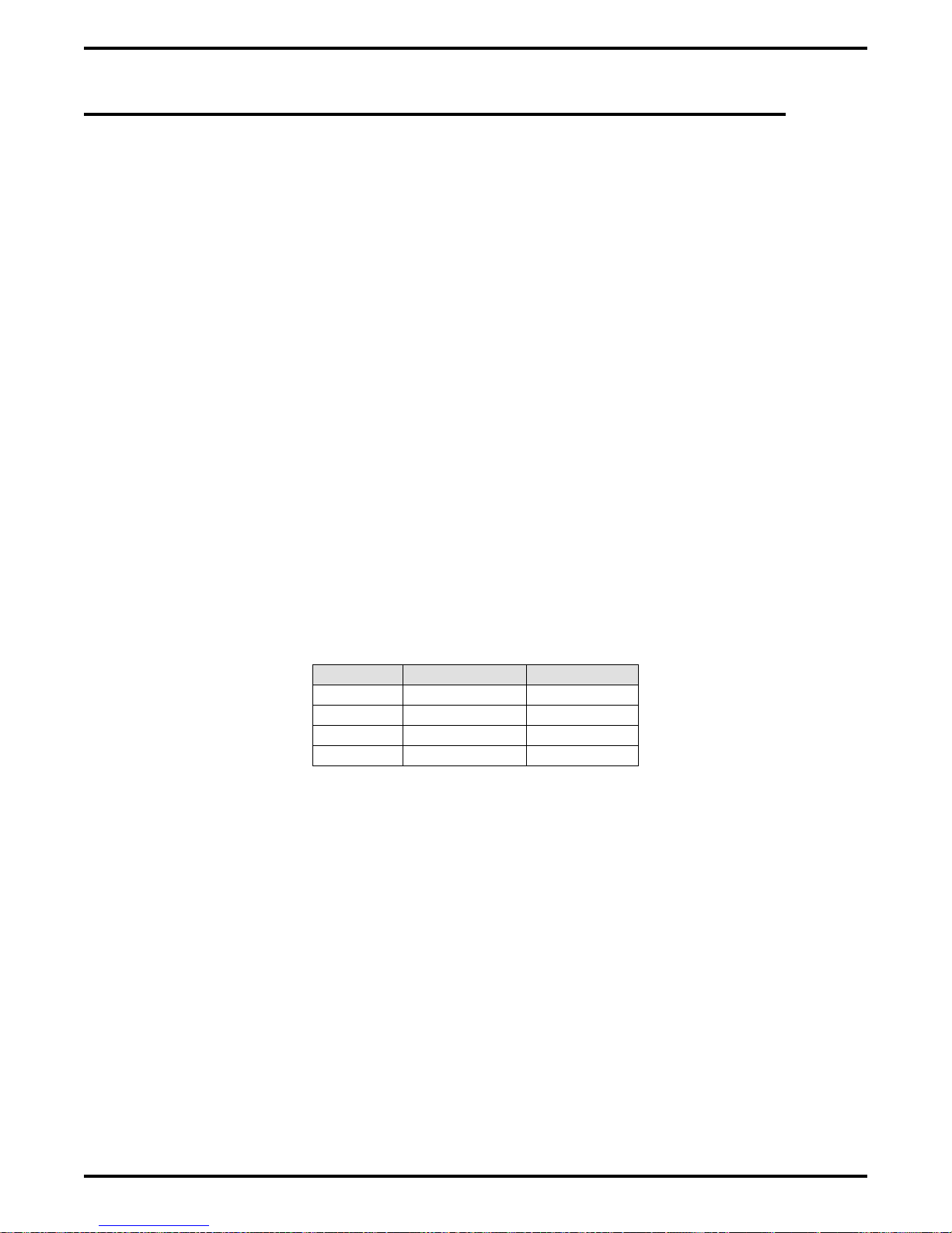
Digital Telephone System IMI66–107
2.12.2 Making The Common Equipment Data Connections
You must make wiring connections from the modular jack (wall jack) to the G0408 and G0816
common equipment cabinets by way of the punch-down-block, while the G1632 cabinet
provides modular jacks for the data connections.
The default data communications format is as follows:
7-bit data with 2 stop bits and no parity
•
Baud rate of 300 baud.
•
Configure a data device to match this format for initial operation or reprogram the system’s data
format to match those of a data device. The tables below list the system’s data ports.
NOTE: The distance between a data device and the common equipment can be up to 500 feet
in a quiet electrical environment. Some sites may require shielded cable for long
runs. For longer distances, you must install limited distance modems to relay the data
communications between the common equipment and a data device.
For G0408 and G0816 cabinets, make data connections at the station connector block as follows:
Clip terminals 37-40 (data port A) and clip terminals 41-44 (data port B).
Table 2–8: Data Connections
Signal Port A Port B
TD = Terminal 37 Terminal 41
RD = Terminal 38 Terminal 42
CTS = Terminal 39 Terminal 43
SG = Terminal 40 Terminal 44
For G1632 cabinets, make data connections at special modular jacks.
2 – 36 Installing The DSU
Page 67

IMI66–107 Digital Telephone System
Station Connector Block Data Ports
(4-line, 8-station base unit and
8-line, 16-station base unit)
1
2
3
4
NOTES:
1.
Maximum distance between
common equipment cabinet
and printer or VDT typically
limited to 500 feet.
Longer distances require
limited distance modems
at either end of run.
2.
Some data devices require
CTS signal for proper
operation. Route to device
as needed.
RS232
Data
Port A
RS232
Data
Port B
{
{
5
6
7
8
9
10
11
12
13
14
15
16
17
18
19
20
21
22
23
24
25
26
27
28
29
30
31
32
33
34
35
36
37
TD
38
RD
39
CTS
40
SG
41
TD
42
RD
43
CTS
44
SG
45
46
47
48
49
50
CLIP TERMIINALS
Modular Jack Data Ports
(16-line, 32-station base unit)
RS232
Data Port B
6 5 4 3 2 1
(Front View of Jacks)
25
50
1 = No connection
RS232
Data Port A
6 5 4 3 2 1
2 = CTS
3 = RD
26
1
4 = TD
5 = SG
6 = No connection
CAJS043D
Figure 2–17: Making Data Connections To The System
Installing The DSU 2 – 37
Page 68

Digital Telephone System IMI66–107
2.12.3 Programming With A Video Display Terminal
You can program the digital telephone system using a telephone or a Video Display Terminal
(VDT). You can connect the VDT directly to the DSU, or you can program the system remotely
using the following equipment:
VDT or a PC and appropriate software program,
•
Pair of data modems.
•
The data modems must be: “Hayes-compatible,” capable of 300-, 1200-, 2400-, or 9600-baud
data speeds, and have auto-answer capability. Be sure to verify the auto-answer capability before
purchasing the units. You are assured of best results if you employ modems of the same make
and model at both the installation site and the remote programming site.
The equipment connections for the customer location are shown in Figure.
1. Determine the signal needs of the modem from the user’s manual for it. (The digital
telephone system only requires TD, RD, and SG but the modems may require more signals.
Check with the modem manufacturer for special requirements).
2. Wire the proper connector (to match the data jack) on one end of a length of multiline cable.
3. Punch down the appropriate leads on the connector block.
4. Connect the network jack of the data modem to an outside telephone line. (If a line is not
reserved for remote programming, have a line switch installed so that on site personnel can
switch the outside telephone line between the data modem and the digital telephone system
cabinet when you are going to perform remote programming.)
5. Refer to the user’s manual for the modem, and program the modem to automatically answer
after the first ring.
6. Interface the VDT or PC with the modem at the programming site per the user’s manuals for
the equipment be used.
7. Establish a communications link for programming the system from a remote site.
If you have had a line switch installed at the customer site, call someone there and ask them
•
to set it for modem operation.
After the outside line is connected to the modem, make the data link between the
•
originating and the remote modems, and perform programming from your remote site just
as if the VDT or PC was connected directly to the system.
2 – 38 Installing The DSU
Page 69
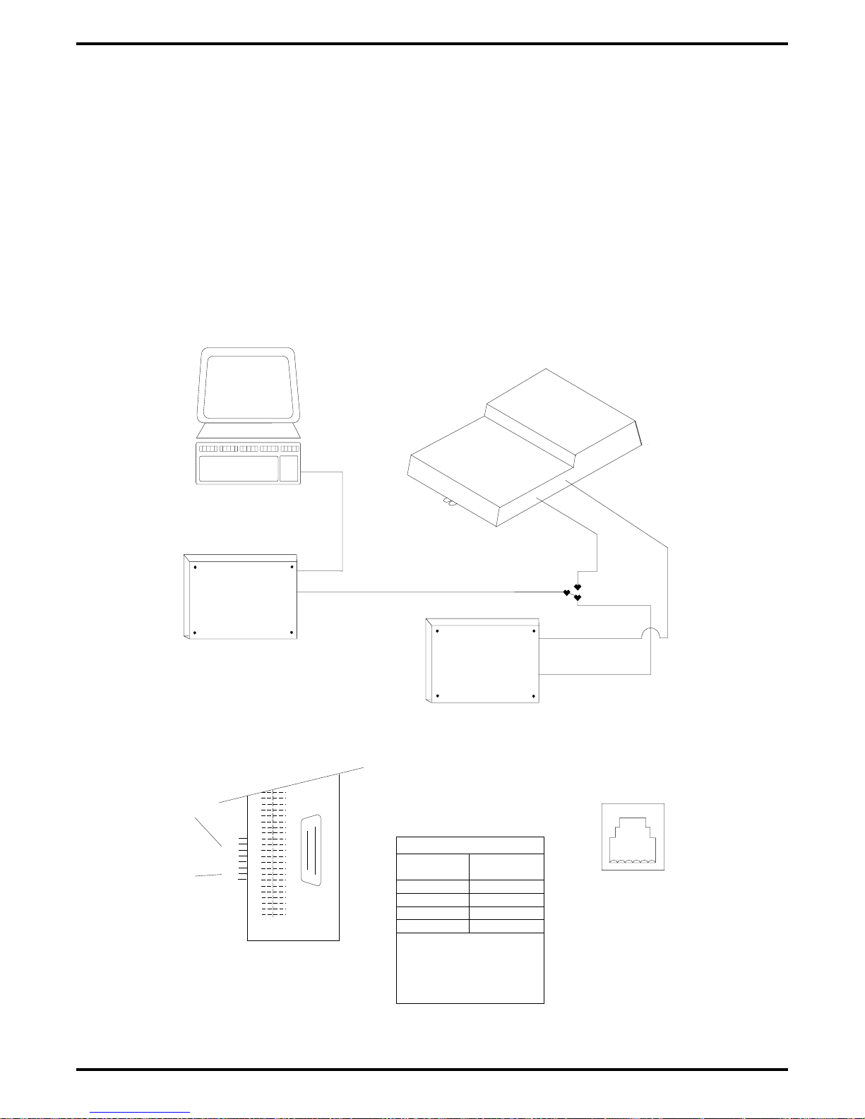
IMI66–107 Digital Telephone System
If you experience difficulty in establishing a communications path between your VDT, modems,
and the digital telephone system, note the following suggestions:
make sure that you have enabled the modem auto-answer feature,
•
confirm that the modems are wired correctly. Reverse connections at pins 2 and 3 if
•
necessary,
check the modem’s instruction manual. You may have to make additional wiring
•
connections,
sometimes you must strap pin 4 to 5, or pin 6 to 7, or pin 6 to 8 to 20 in the modem wiring.
•
Check the modem’s installation manual for this requirement,
use a breakout box data tester to troubleshoot the data communications lines.
•
Video Display Terminal Or
Personal Computer
Data
Modem
Station Connector Block Data Ports
(4-Line, 8-Station Base Unit and
8-Line, 16-Station Base Unit)
RS232
DATA
PORT A
RS232
DATA
{
{
TD
RD
CTS
SG
TD
RD
CTS
SG
PORT B
37
38
39
40
41
42
43
44
45
46
47
48
49
50
CLIP TERMIINALS
Data
Jack
Network
Jack
25
50
26
1
Typical Common
Equipment Cabinet
Telco Network
Data
Modem
DATA CONNECTIONS
SYSTEM
DATA PORT
CTS
RD
TD
SG
System requires that the CTS
pin be at a high logic level
before it will send data. It will
force the pin high if no modem
connection is supplied.
MODEM
DATA JACK
-TD
RD
SG
Data
Port
Line
Port
Line
Switch
Data Jack
Network Jack
Modular Jack Data Ports
(16-Line, 32-Station Base Unit)
RS232
DATA PORTS
654321
(Front View of Jack)
1=-2=CTS
3=RD
4=TD
5=SG
6=--
CAJS013
Figure 2–18: Installing a Video Display Terminal
Installing The DSU 2 – 39
Page 70
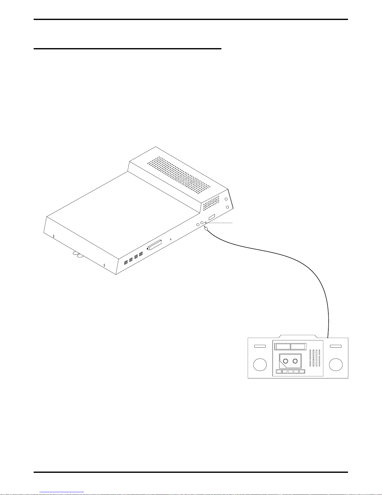
Digital Telephone System IMI66–107
2.13 Using The Music Interface
If music is to be part of the system, connect a customer-provided music source to the common
equipment music interface jack (phono jack) provided for this purpose. The impedance of this
input is approximately 500Ω. Use the volume control on the music source to adjust the audio
level of the music as required.
CAJS088
Typical
Common Equipment
(8-Line, 16-Station
Base Unit Shown)
Music Interface
Music Source
2 – 40 Installing The DSU
(for music on hold
and background music)
Figure 2–19: Using The Music Interface
Page 71
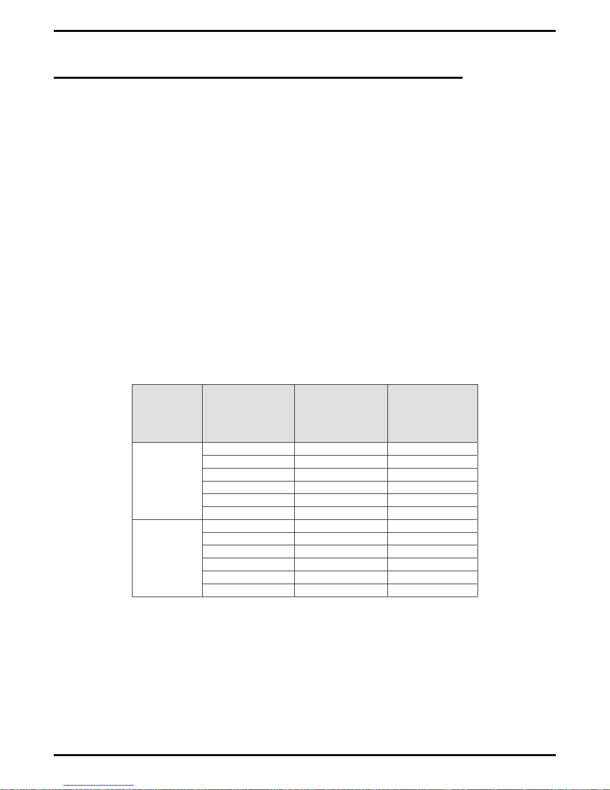
IMI66–107 Digital Telephone System
2.14 Using The Add-On Expansion Module
You can install one or two optional add-on expansion modules on the common equipment base
unit to increase the line and station capacity of an installed system.
The default numbering of the expanded lines and stations begin with the next higher line or
station port number from that provided by the host base unit. The numbering continues
sequentially from top module to bottom module if two modules are installed. For example: The
defaulted 8-line, 16-station base unit provides station ports 10 through 25 and lines 1 through 8.
When installed, a 408 Expansion module will provide station ports 26 through 33 and lines 9
through 12 thus creating a 12 line by 24 station system.
Each expansion module provides a tip and ring pair as an emergency power failure circuit. This
circuit is connected to the first module-provided line.
The line connections of the expansion module are available at two modular jacks. When facing
the jack openings, lines 1 and 2 are provided by the jack on the right and lines 3 and 4 are
provided by the jack on the left.
Table 2–9: Connecting Lines To The G0408 Expansion Module
Line
Jack
1
2
Pin
Number Connection
1 No Connection
2 Line 2M Tip
3 Line 1M Tip
4 Line 1MRing
5 Line 2M Ring
6 No Connection
1 No Connection
2 Line 4M Tip
3 Line 3M Tip
4 Line 3M Ring
5 Line 4M Ring
6 No Connection
Telephone
Number
Installing The DSU 2 – 41
Page 72
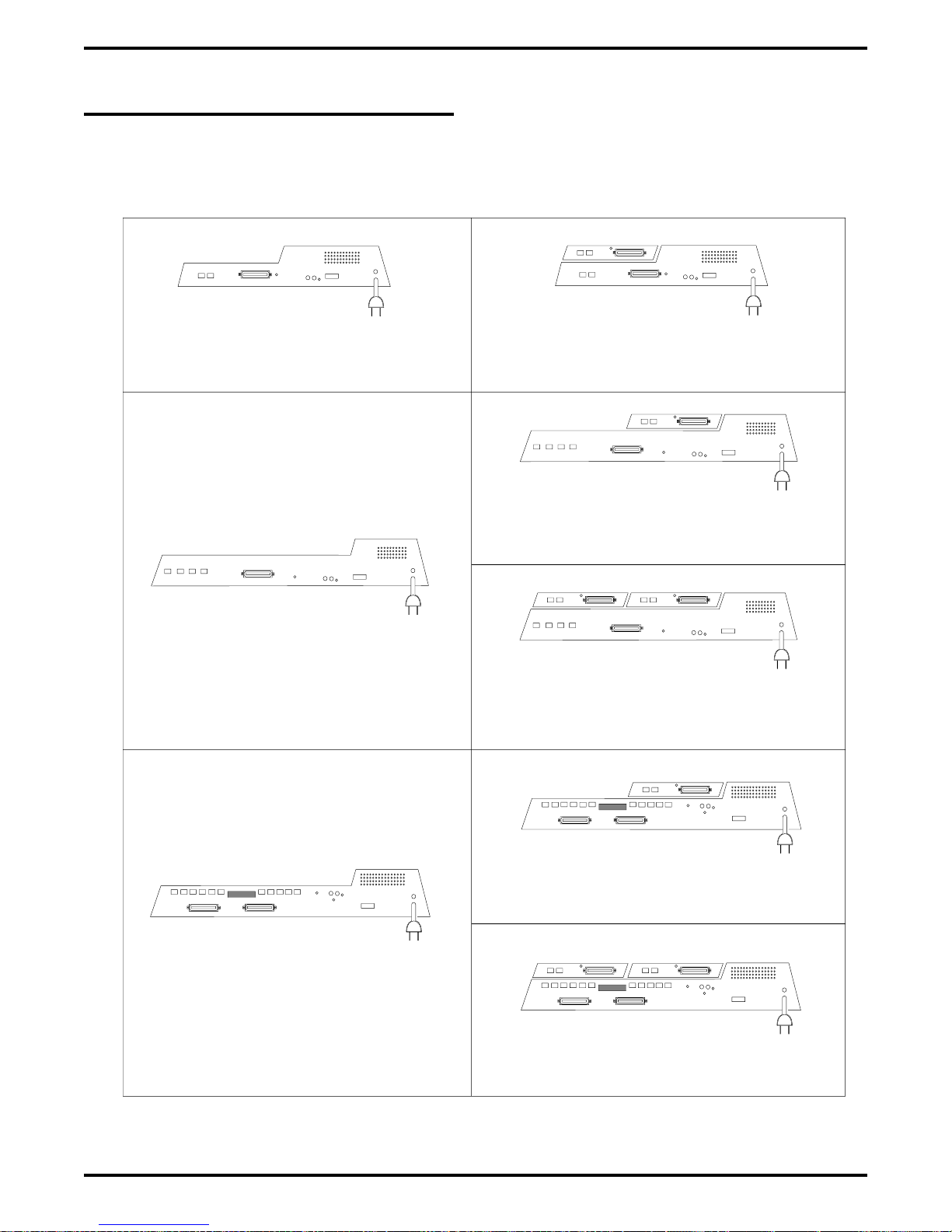
Digital Telephone System IMI66–107
2.14.1 Expansion Capabilities
The 4-line 8-station expansion module adds station and line capability in several different
combinations.
4-Line, 8-Station Base Unit
8-Line, 16-Station Base Unit
24-Port System
8-LINES AND 16-STATIONS
(BASE UNIT PLUS ONE EXPANSION MODULE)
36-Port System
12-LINES AND 24-STATIONS
(BASE UNIT PLUS ONE EXPANSION MODULE)
48-Port System
16-LINES AND 32-STATIONS
(BASE UNIT PLUS TWO EXPANSION MODULES)
16-Line, 32-Station Base Unit
Figure 2–20: Add-On Expansion Module Capabilities
2 – 42 Installing The DSU
60-Port System
20-LINES AND 40-STATIONS
(BASE UNIT PLUS ONE EXPANSION MODULE)
72-Port System
24-LINES AND 48-STATIONS
(BASE UNIT PLUS TWO EXPANSION MODULES)
Page 73

IMI66–107 Digital Telephone System
2.14.2 Connecting Stations To The Expansion Module
The station connections are available at a 50-pin connector.
Table 2–10: Connecting Stations To The G0408 Expansion Module
25-Pair Connections Two-Wire Connections Station Connections
Wire Color Pair Pin No.
White-Blue
Blue-White 1 2 Red
White-Orange
Orange-White 2 4 Red
White-Green
Green-White 3 6 Red
White-Brown
Brown-White 4 8 Red
White-Slate
Slate-White 5 10 Red
Red-Blue
Blue-Red 6 12 Red
Red-Orange
Orange-Red 7 14 Red
Red-Green
Green-Red 8 16 Red
Red-Brown
Brown-Red 9 18
Red-Slate
Slate-Red 10 20
Black-Blue
Blue-Black 11 22
Black-Orange
Orange-Black 12 24
Black-Green
Green-Black 13 26
Black-Brown
Brown-Black 14 28
Black-Slate
Slate-Black 15 30
Yellow-Blue
Blue-Yellow 16 32
Yellow-Orange
Orange-Yellow 17 34
Yellow-Green
Green-Yellow 18 36
Yellow-Brown
Brown-Yellow 19 38
Yellow-Slate
Slate-Yellow 20 40
Violet-Blue
Blue-Violet 21 42
Violet-Orange
Orange-Violet 22 44
Violet-Green
Green-Violet 23 46
Violet-Brown
Brown-Violet 24 48
Violet-Slate
Slate-Violet 25 50 Ring
1
2
3
4
5
6
7
8
9
10
11
12
13
14
15
16
17
18
19
20
21
22
23
24
25
26 1
27 3
28 5
29 7
30 9
31 11
32 13
33 15
34 17
35 19
36 21
37 23
38 25
39 27
40 29
41 31
42 33
43 35
44 37
45 39
46 41
47 43
48 45
49 47
50 49
Clip
Term.
Pair Wire Color Station Location
Signal Path
Signal Path
Signal Path
Signal Path
Signal Path
Signal Path
Signal Path
Signal Path
Signal Path
Green
Green
Green
Green
Green
Green
Green
Green
Tip
1M
2M
3M
4M
5M
6M
7M
8M
Spare Pair
Power Fail Station
Installing The DSU 2 – 43
Page 74

Digital Telephone System IMI66–107
2.14.3 Installing The Add-On Expansion Module
Each add-on expansion module measures 15.5" wide x 9.4" high x 1.6" wide and weighs
approximately 4 pounds. The modules are designed so that you can attach them to the base unit
and connect them to it via cabling.
NOTE: If you plan to upgrade the system software at the same time that you add expansion
modules, be sure to add the expansion modules first by following steps 1 through 11.
After you have installed the expansion modules and programmed for the new stations
and line ports, you can then upgrade the software as described in the discussion
titled, Upgrading The System Software.
To install an expansion module to a base unit, follow the procedure detailed in steps 1–11.
CAUTION
You must always connect the first module to the top location on the base unit.
1. Disconnect both AC power and external battery back-up power from the system.
2. Remove and set aside nameplate from base unit. This action exposes internal cable connector
on base unit circuit board.
3. Reach through opening in base unit and mate module cable plug with base unit circuit board
connectors.
4. Push excess cable inside base unit housing through connector opening.
5. Install expansion module in place on all four mounting holes. Be sure excess cable is not
pinched between add-on module and base unit.
6. Pull module down to latch in place.
7. Use flat-blade screw driver to tighten module securing screw into base unit threaded fastener.
8. Snap nameplate into slots on top of module housing.
9. Attach #10 or #12 insulated, solid copper wire between the frame ground stud on the
expansion module and the frame ground stud on the common equipment cabinet.
10. Reconnect the power to the system.
11. Refer to Chapter 3, and perform configuration programming for new station and line ports.
2 – 44 Installing The DSU
Page 75

IMI66–107 Digital Telephone System
Typical Base Unit
(8-Line, 16-Station Base Unit)
Nameplate
(Remove to expose base
Top
Location
unit connectors)
Upper Mounting Holes
(2 Places)
Bottom
Location
AM012
Connecting Cable
and Plug
Typical Add-On Module
Lower Mounting Holes
(2 Places)
Ground
Modules
to Base
Unit
Securing
Screw
Snap Slots for
Nameplate
Figure 2–21: Installing The Add-On Expansion Module
Installing The DSU 2 – 45
Page 76

Digital Telephone System IMI66–107
2.15 Upgrading The System Software
The following sections contain information on safety precautions you should take before
working on the common equipment, procedures for making a copy of the call cost records before
upgrading software, instructions for replacing the software cartridge, and instructions for master
clearing the system to load the new software.
2.15.1 Creating A Static Safe Work Area
CAUTION
Circuit boards are susceptible to damage caused by electrostatic discharge, and you must keep
this fact in mind as you handle them.
When servicing the common equipment cabinet, it is a good practice to prepare a static-safe
work area on which to service the cabinet.
Supply yourself with a static discharge wrist strap, and wear it every time you handle electronic
circuit boards either at the cabinet mounting location or at your work area.
Figure 2–22: Creating A Static Safe Work Area
2 – 46 Installing The DSU
Page 77

IMI66–107 Digital Telephone System
2.15.2 Saving The Call Cost Records
To save the call cost records,
1. Make a copy of the call cost records and then delete them from the system memory per the
following procedure:
To print records: press INTERCOM, dial ✳ # 076#, and press SPEAKER.
To delete records: press INTERCOM, dial ✳ # 077#, and press SPEAKER.
2. Use the VDT programming procedure to save the current system data base on a PC.
Installing The DSU 2 – 47
Page 78

Digital Telephone System IMI66–107
2.15.3 Replacing The Software Cartridge
Upgrading software in the digital telephone system consists of removing the current software
cartridge and exchanging it with a board containing updated software.
CAUTION
To avoid any chance of electrostatic discharge damage to the softtware cartridge, avoid
touching the connector with your fingers while handling it. Be sure to disconnect the AC
power and battery back up to the base unit before installing or removing a software cartridge.
To remove a cartridge,
1. Place the end of a flat-blade screwdriver into the removal notch. Lift up on the cartridge with
the screwdriver to un-mate the connections.
2. Slide the cartridge out of the base unit.
NOTE: Only replacement software designed for a particular cabinet may be put in that
cabinet. Example: Only 408 software will work in the 408 cabinet.
To install a cartridge,
1. Orient the cartridge so that the connector end is toward the base unit opening. The removal
notch, located at the top rear of the cartridge, should point to the front of the base unit.
2. Gently insert the cartridge into the base unit cabinet until it seats into place. Press down on
the cartridge to secure the connection.
2 – 48 Installing The DSU
Page 79

IMI66–107 Digital Telephone System
CAJS091A
Typical
CommonEquipment
BaseUnit
Software
Cartridge
(Liftout toremove)
Typical
CommonEquipment
BaseUnit
Figure 2–23: Removing The Software Cartridge
CAJS091
Software
Cartridge
(Pushin to install)
Figure 2–24: Installing The Software Cartridge
Installing The DSU 2 – 49
Page 80

Digital Telephone System IMI66–107
2.15.4 Master Clearing The System
To reboot the system and load the new software,
1. Restore power to the system.
2. Perform the master clear procedure from the VDT or at the programming station as follows:
press INTERCOM,
•
dial ✳ # 746 ✳,
•
dial 90,
•
dial 51684,
•
press SPEAKER.
•
3. Use the VDT programming procedure to re-load the system data base into the system
memory.
2 – 50 Installing The DSU
Page 81

IMI66–107 Digital Telephone System
2.16 Checking The System Installation
The system operating features are set to default conditions at initial power-up. These conditions
provide a basic operating system with a known set of parameters, and you should check out the
system with the default conditions in place. At any time while the system is operating, you can
reset default conditions from station port 10 or 12 following the instructions provided in chapter
3, Programming.
2.16.1 Checking The Resistance
Measure the resistance at the station connector blocks under the following conditions.
AC power cord disconnected from electrical outlet.
•
Common equipment connected to station connector blocks.
•
Stations wired and wiring punched down on blocks.
•
Bridging clips removed from blocks to isolate stations from common equipment.
•
Measure the resistance of each installed station and wiring from the station side of the connector
blocks. Resistance values will vary with cable length and station type but should be within the
following limits:
Greater than 700 KΩ
•
2.16.2 Checking The Voltage
Make the following voltage measurements at the station connector blocks under the following
conditions:
Bridging clips installed
•
AC power connected to the common equipment
•
Measure the voltage across the signal pair. The measured voltage must be within the following
limits:
28–36 VDC
•
Installing The DSU 2 – 51
Page 82

Digital Telephone System IMI66–107
2.16.3 Checking The General Operating Conditions
1. Check the red light emitting diode (LED) system status indicator. Be sure that it is on steady.
If it is off or flashing, refer to the paragraph titled Checking the System Status Indicator.
2. Refer to the user’s guide for operating information and perform a general operational test of
the system by exercising the features from station port 10 or 11. Operational parameters are
per the system default conditions as detailed in Chapter 4 until class of service programming
is performed.
3. Once the basic system is verified as operational, perform the class of service programming as
described in Chapter 3.
2 – 52 Installing The DSU
Page 83

IMI66–107 Digital Telephone System
2.17 Isolating Failures
Section 2.17 will help you to find and identify problems that might occur in the digital telephone
system.
2.17.1 Checking The System Status Indicator
A red LED located on the common equipment cabinet near the music port is the system status
indicator. This indicator light comes on when power is supplied to the system. If the indicator
flashes after power up, it signals that the processor has failed or that the software cartridge is not
installed. Unplug and reconnect the AC power to the power supply and observe the LED
indication. If it still shows a flashing indication, equipment replacement may be necessary.
2.17.2 Testing The Stations
To test the multiline stations for proper operation:
1. Disconnect line cord at station base.
2. On DigiTech telephones, press and hold the MUTE button.
On Impact and Impression telephones, press and hold 1 on the keypad.
Station will automatically perform self test routine.
3. Release test button as soon as test begins. Sequence of test is as follows:
a. indicators will light in sequence,
b. ringer will sound—be sure volume is set to low or high,
c. indicators and ringer will then turn off at the same time.
4. Replace any station that does not pass the self test.
Installing The DSU 2 – 53
Page 84
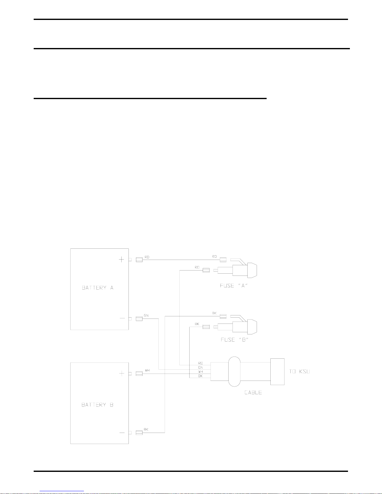
Digital Telephone System IMI66–107
2.18 Installing The System Options And Accessories
This section contains information on installing the battery back up, the analog terminal interface,
and the data interface unit.
2.18.1 Installing The Battery Back Up Assembly
Preparing The Battery Back Up Assembly For Use
The factory ships the battery back up assembly with the harness installed in the enclosure. To
complete the assembly, perform the following operations:
remove the lid from the metal enclosure and save the retaining hardware,
•
install the batteries in the metal enclosure and connect the wiring per the schematic shown
•
below,
replace the lid.
•
You can wall mount the battery back up enclosure if you wish. If you do, follow the same
guidelines and instructions for mounting the common equipment cabinet as set forth at the
beginning of this chapter.
batt3.cdr
2 – 54 Installing The DSU
Figure 2–25: Wiring The Batteries
Page 85
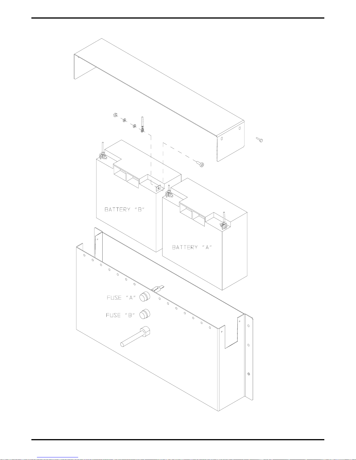
IMI66–107 Digital Telephone System
batt1.cdr
Figure 2–26: Installing The Batteries
Installing The DSU 2 – 55
Page 86

Digital Telephone System IMI66–107
Connecting The Battery Back Up Assembly
The common equipment provides an interface connector for the connection of an optional
external battery assembly.
CAUTION
Be sure that the AC power cord is connected to the electrical outlet before connecting an
external battery assembly to the common equipment interface connector. This ensures that
internal protection circuitry is operating to prevent damage that could result from improper
connection.
The external battery assembly provides a minimum of one hour of operation should the AC
power to the system be interrupted. The assembly has a 15 ampere-hour current rating and is
fused with the following vaue: 4A 250V 3AG type.
The external battery assembly may include batteries from either of the following suppliers:
Model PS-12150 from Power-Sonic Corporation, Redwood City CA, 94032
•
Model PE12V15 from GS PORTALAC, City Of Industry CA, 91748
•
The minimum battery backup time for a fully configured system can be calculated using the
formula:
Back Up Time (in hours) =
K(15)
1 + [(0.1) (N)]
K (Constant) = 0.9 for G0408 with or without a GM408 module
0.8 for G0816 with or without GM408 modules
0.8 for G1632 with or without GM408 modules
15 = ampere-hours
N = total number of stations
Example:
Assume that a G1632 system plus two GM408 modules are installed along with the optional
battery assembly to provide back-up power.
Back up time =
(0.8) (15)
1+[(0.1) (48)] 5.8
12
=
= 2.1 Hours
2 – 56 Installing The DSU
Page 87

IMI66–107 Digital Telephone System
During AC operation, the common equipment provides recharging current to maintain the
voltage potential of the external battery assembly at an operational level. The charging circuit
may not provide an adequate charge if an installed battery assembly has a current rating of
greater than 40 ampere-hours. You should measure the battery assembly voltage every three
months.
For proper backup capabilities, make sure the batteries meet the following specifications:
With a fully-charged battery assembly disconnected from the common equipment, the
•
measured voltage must be greater than 12 VDC but should not exceed 13.5 VDC.
With a fully-charged battery assembly connected to the common equipment, the measured
•
voltage should be less than 13.8 VDC. If the voltage measures higher than this limit,
contact your Comdial Technical Services representative.
The open output of the common equipment battery charger connection measures 13.6–13.8
•
VDC. If the charging voltage measures higher or lower than this range, contact you
Comdial Technical Services representative
An optional external battery assembly requires approximately 10 hours to completely
•
re-charge to full potential after it has been completely discharged and, in some cases, when
initially installed.
Figure 2–27: Connecting The Battery Back Up Assembly
Installing The DSU 2 – 57
Page 88

Digital Telephone System IMI66–107
2.18.2 Installing The Analog Terminal Interface
Introducing The Analog Terminal Interface
The ATI-D is a multipurpose, on-premise accessory for the digital telephone system. It has dual
circuits that provide the following features:
INDUSTRY-STANDARD TELEPHONE (IST) INTERFACE—This feature adapts most
•
industry-standard telephone (IST) devices to the digital telephone system. The ATI-D will
accept both tone (DTMF) and pulse (rotary) dialing from these devices.
SYSTEM INTERCONNECTION—This feature allows an installer to connect two digital
•
telephone systems to each other using two ATI-Ds and on-premise wiring. When
interconnected, either telephone system treats the other telephone system as an IST device.
The two telephone systems are not integrated together and do not share features.
MODEM ADAPTER—This feature allows the flow of switched data between a data source
•
and a data receiver through the digital telephone system.
VOICE MAIL/ANSWERING MACHINE INTERFACE—This feature allows an installer
•
to connect voice mail systems and automated answering devices to the digital telephone
system.
CAUTION
The ATI-D by itself does not support any off-premise service. Never connect the ATI-D to a
telephone company-supplied line unless you have first installed an acceptable OPX long loop
adapter.
The ATI-D is housed in a self-contained metal enclosure that can be wall mounted if desired.
The ATI-D is powered by the digital telephone system through the station port connections and
employs an internal ringing generator to generate a ringing signal for an IST. Dual, high-quality,
low-loss, balanced, telephone transmission circuitry supports two IST inputs.
One 2-pair cable (four-wire) connects the ATI-D to two common equipment station ports. A
single pair of wires connects the external analog IST equipment to the ATI-D. Modular
connectors are provided to allow quick connections.
Each ATI-D circuit drives a load with a maximum ringer equivalence number (REN) of 2.0, thus
allowing more than one IST connection at each interface input. Check the REN number of the
connected IST equipment so as not to exceed the capacity of the ATI-D. Improper operation
may result if the REN maximum of the ATI-D is exceeded.
The ATI-D supports a wide variety of IST equipment such as 500 and 2500-type telephones,
cordless telephones, voice mail systems, answering machines, FAX machines, and data modems.
2 – 58 Installing The DSU
Page 89

IMI66–107 Digital Telephone System
Detailing The The Analog Terminal Interface Specifications
Power requirements: Supplied by the common equipment
Ringing voltage: 55 VAC Nominal @ 20 Hz
(45 VAC minimum)
Power rated to maximum
REN = 2.0
Battery feed voltage: 24 VDC nominal
Loop current limits between ATI-D
and IST interface: 20 ma min. at 620 ohms
70 ma max. at 0 ohms
DC loop limits from ATI-D to
industry standard interface per port: 620 ohms maximum including interfaced telephony device.
(Approximately 4000 feet with #26 AWG twisted-pair cable
and 300 ohm device load.)
(Approximately 500 feet if two IST devices are connected in
parallel on same tip and ring pair.)
DC loop limits from ATI-D to voice
mail system: Approximately 1000 feet with #26 AWG twisted-pair cable.
Cable insulation resistance: 30,000 ohms minimum
Cable requirement ATI-D to system 2-pair twisted cable; 25 feet maximum length. (Both common
equipment station ports must always be connected to the
ATI-D for every installation, and they must be paired in
sequence — 12 & 13, 14 & 15, etc.)
Cable terminations: 623-type, 4-conductor mini jacks
Dialing: Industry-standard DTMF or Dial pulse (rotary) with nominal
make/break ratio of 40/60 @ 10 PPS
Ringing cadence: Outside calls = 2 second on -
4 seconds off
Intercom calls = Two bursts:
1 second on - .5 second off,
1 second on - 3.5 seconds off
Operating temperature: 32-122 F (0-50 C)
Humidity: 90 % relative, non-condensing
Height: 2.375 inches
Width: 8.062 inches
Length: 11.125 inches
Weight: 4 lbs. (plus 2 lbs.
FCC registered and listed for safety compliance as part of digital telephone system
FCC certified, Part 15 (class A)
for packing material)
Installing The DSU 2 – 59
Page 90

Digital Telephone System IMI66–107
Mounting The Analog Terminal Interface
Refer to Section 2.1 at the beginning of this chapter for system mounting considerations that are
also applicable to the analog terminal interface.
Mounting Procedure
1. Unpack and carefully inspect the ATI-D for shipping damage. Notify the shipper
immediately of any damage found. Verify that the package contains all parts and accessories
needed for proper installation and operation.
2. If a backboard is required at the mounting location, attach it securely to provide a stable
mounting surface.
3. Use the base of the ATI-D as a template or measure for mounting hole locations per the
dimension details shown in the illustration on the next page.
4. Drill holes of a proper size to accommodate the hardware being used into the mounting
surface. If necessary, prepare these holes with inserts, anchors or other attachment devices as
dictated by the type of mounting surface.
5. Insert the two top screws into the mounting surface and tighten them to within approximately
1/8-inch of the surface.
6. Hang the ATI-D on the top screws using the mounting holes located on the rear of the
cabinet. Note that these holes are elongated with an enlargement at one end. This feature
allows the cabinet to snap down on the screws to secure the mounting when the cabinet is
hung on them.
7. Insert a third screw through the mounting tab located on the lower edge of the cabinet and
into the mounting surface; tighten it into place.
2 – 60 Installing The DSU
Page 91
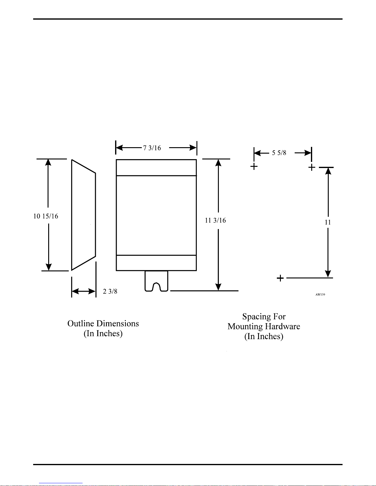
IMI66–107 Digital Telephone System
Figure 2–28: Detailing The ATI-D Dimensions
Installing The DSU 2 – 61
Page 92

Digital Telephone System IMI66–107
Connecting The Analog Terminal Interface
Connect the ATI-D per the diagram detailed on the following page. A grounding wire is not
required for operation; however, one is desirable for decreasing radio frequency interference and
electrostatic discharge susceptibility. The ATI-D housing provides a frame ground stud for this
purpose. Connect a #10 or #12, insulated, solid copper wire between this ground stud and a
reliable earth ground.
NOTE: You must connect both station ports to the ATI-D, even if you plan to use only one
IST device. Connect the first ATI-D port to an even station port. All ATI-D ports must
be paired.
CAUTION
Be careful when connecting the wiring between the common equipment and the ATI-D. Be
sure to connect the common equipment station ports to the COMMON EQUIPMENT (KSU)
jack on the ATI-D. Damage to the ATI-D could occur if this wiring is mistakenly connected to
the IST jack.
Use a voltmeter to check for the presence of voltage on the ATI-D IST jack.
1. Be sure that you have installed all the wiring between the ATI-D and the common equipment
station ports.
2. Measure for DC voltage on IST jack:
—Measure between TIP leads and common equipment grounding stud.
—Measure between RING leads and common equipment grounding stud.
—Measure between TIP leads and RING leads.
The measured voltage must be within following limits:
MEASUREMENT VOLTAGE
Tip to Ground +3 to +11 VDC
Ring to Ground -13 to -21 VDC
Tip to Ring +23 to +25 VDC
(The TIP lead is positive with respect to the RING lead.)
Installing A Voice Mail Interface
You can use the ATI-D to provide interfacing for a customer-supplied voice processing system.
The ATI-D, using paired station ports (such as 12 and 13 or 14 and 15), will support two voice
mail ports.
To complete the installation, connect the voice mail ports to the IST jacks on the ATI-D.
2 – 62 Installing The DSU
Page 93

IMI66–107 Digital Telephone System
Typical Station
Connector Block
1
2
3
4
5
6
7
8
9
10
11
12
13
14
15
16
17
18
19
20
21
22
23
24
25
26
27
28
29
30
31
32
33
34
35
36
37
38
39
40
41
42
43
44
45
46
47
48
49
50
CLIP TERMINALS
25
50
26
1
Connect to Station Connector Jack
Common
Equipment
Jack
Common Equipment Jack
PIN 1 No Connection
PIN 2 Odd Station (Tip)
PIN 3 Even Station (Tip)
PIN 4 Even Station (Ring)
PIN 5 Odd Station (Ring)
PIN 6 No Connection
PIN Locations On
ATI3
Jacks - Front View
Earth
Ground
(Optional)
Line Jack
Line Jack
PIN 1 No Connection
ATI-D
PIN 2 IST 2 (Tip)
PIN 3 IST 1 (Tip)
PIN 4 IST 1 (Ring)
PIN 5 IST 2 (Ring)
PIN 6 No Connection
6
5
4
1
2
3
On-Permise IST Jacks 1 and 2
Figure 2–29: Interconnecting The ATI-D
Installing The DSU 2 – 63
Page 94

Digital Telephone System IMI66–107
Installing An OPX Long Loop Adapter For Off-Premise Service
As stated previously, the analog terminal interface is an on-premise device. You must use an
OPX long loop adapter if you wish to adapt the ATI-D to support an off-premise application. An
OPX long loop adapter connects to a single telephone line and can greatly extend the line’s loop
length (the Proctor Model 46222 adapter*, for example, can extend line length to 30,000 feet).
*Proctor & Associates Company, Redmond WA
CAUTION
When you connect an adapter to an off-premise extension (OPX), you must install primary
protectors in series with the tip/ring pair of the telephone line that is routed to the OPX. This
action is necessary to protect both the user and the equipment from transient voltage spikes
that can travel through the cable. The telephone company offers basic protection against this
condition; however, that protection is usually designed to safeguard the central office circuits
and you cannot rely upon it to protect common equipment. To help insure that external
overvoltage surges do not damage the system, installation specialists recommend that you
install and properly ground gas discharge tubes or similar primary protection devices on the
telephone line that routes between the adapter and the OPX.
To install the OPX long loop adapter:
Follow manufacturer’s instructions for unpacking, inspecting, mounting and wiring the
•
adapter unit.
Plug a modular cable into the system jack on the adapter and connect the opposite end of
•
the cable to the IST jack on the ATI-D.
Plug a modular cord into the telephone jack on the adapter and connect the opposite end of
•
the cord to the OPX line (see Figure 4).
Plug the adapter power cord into a standard 117 VAC, 3-wire electrical outlet.
•
2 – 64 Installing The DSU
Page 95

IMI66–107 Digital Telephone System
Typical Station
Connector Block
1
2
3
4
5
6
7
8
9
10
11
12
13
14
15
16
17
18
19
20
21
22
23
24
25
26
27
28
29
30
31
32
33
34
35
36
37
38
39
40
41
42
43
44
45
46
47
48
49
50
CLIP TERMINALS
25
50
26
1
Connect to station connector
jack on common equipment.
CAJS106
Common
Equipment
Jack
4
2
3
5
Earth
Ground
(Optional)
OPX
Long Loop
Adapter
ATI-D
117 VAC
IST Jack
4
2
3
5
On-Premise IST Jack
Off-Premise IST Jack
Figure 2–30: Installing The Long Loop Adapter
Installing The DSU 2 – 65
Page 96

Digital Telephone System IMI66–107
Understanding The Programming Requirements
The ATI-D provides the interfacing capability required to connect most IST equipment to a
station port of an digital telephone system.
The IST provides basic intercom service coupled with the ability to access outside lines.
Through programming, the IST acts as either as an intercom-only telephone or as a full-featured
business telephone. You can program the station port through which the IST is being interfaced
either for prime intercom or for prime line automatic and idle line preference. Default is for
prime intercom. You can also program the station port for outside line ringing and to match the
type of dialing method employed by the IST.
Prime Intercom
On key configured systems, telephone users can extend line access to the IST for call
origination through the use of the call transfer feature. Through programming, you can assign
outside line ringing to the IST even though it is programmed for prime intercom access. To do
this, program the station port for the ringing line preference feature and enable ringing for all
desired lines.
On hybrid configured systems, the system gives the IST access to outside lines through line
group access. With line group access, IST users dial the group access code over the intercom line
to access an outside line for use. The common equipment then selects one of the grouped idle
lines for use in the order from the highest numbered line to the lowest numbered line.
Prime Line Automatic Or Idle Line Preference
Program an outside line as a prime line at the station port through which the IST is being
interfaced, or program the station port for idle line preference and then program one of the
assigned idle lines as a prime line.
With both prime line automatic and idle line preference features, the IST has outside line dial
tone when the user lifts the handset. Through programming, you can assign outside line ringing
to the IST station port that you have programmed for prime line automatic or for idle line
preference. Alternately, you can enable the ringing line preference feature for the station port.
The intercom line is available to an IST even though you have arranged it to have outside line
access. After going off-hook, the IST user obtains intercom dial tone by performing a hookflash.
To perform a hookflash, he or she must press and release the hookswitch. This action either
drops the outside line (if no digits are dialed after lifting the handset) or places it on hold (if
digits were dialed) and provides intercom dial tone.
2 – 66 Installing The DSU
Page 97

IMI66–107 Digital Telephone System
ATI-D Distinctive Ringing
Intercom calls that ring at equipment connected through an ATI-D have a different cadence than
outside calls. Intercom ring cadence is: 1 sec. on, .5 sec. off, 1 sec. on, 3.5 sec. off. Outside call
ring cadence is: 2 sec. on, 4 sec. off. You can program disable this distinctive ringing feature to
make the intercom ring cadence the same as that for outside calls.
Through Dialing
You can program the station port that interfaces the IST for through-dialing if you wish or you
can disable this feature. The system automatically enables this feature when you connect the
ATI-D to the station port. If the IST is a dual-tone multi-frequency (DTMF) tone dial device,
dialing tones generated by it pass through the ATI-D, the common equipment and onto a tone
dial compatible telephone line. In this case, the station port must have through-dialing enabled.
However, if you use a rotary telephone as an IST device, you must disable through-dialing.
Installing The DSU 2 – 67
Page 98
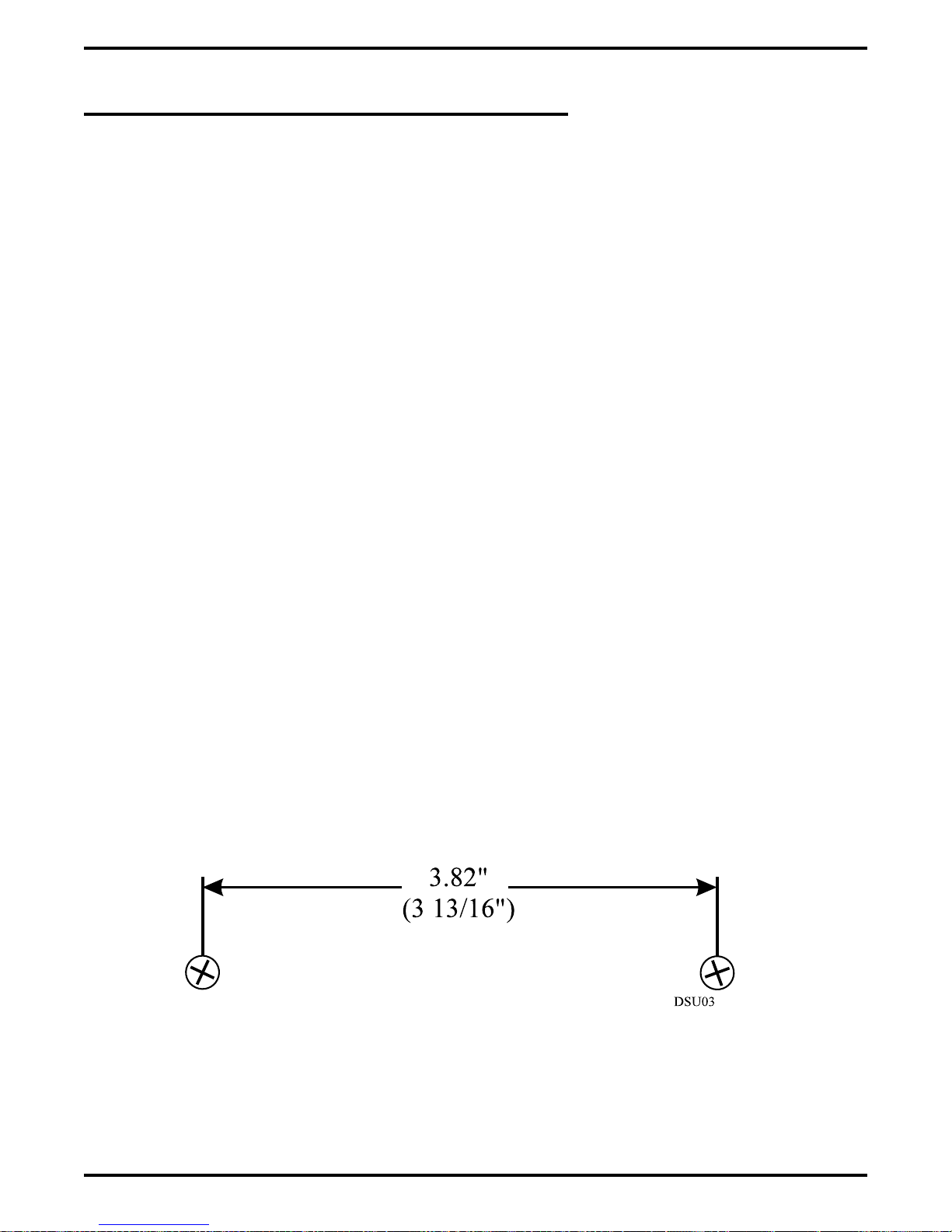
Digital Telephone System IMI66–107
2.18.3 Installing The Data Interface Unit
Unpack the Data Interface Unit (DIU) and check for the following parts:
Telephone line cord
•
Power cable with attached transformer.
•
Verify that the Digital Service Unit (DSU) contains software revision 17A or later. If you need
to upgrade the DSU software, see the section entitled “Software Cartridge.”
Installing The Mechanical Components
You can install the DIU in either a free-standing manner or you can mount it on a wall.
When mounting the DIU on a wall:
1. Select a location that is close to a standard 115 VAC electrical wall outlet. The location you
select should also be convenient to the digital telephone and the Industry Standard Telephone
(IST), FAX, or modem—whichever one you will be connecting to the DIU.
2. Once you have selected the location for mounting the DIU, mark two locations for the
mounting screws as follows:
a. make the first mark,
b. measure 3 13/16 inches horizontally from the first mark and make the second mark.
2 – 68 Installing The DSU
Figure 2–31: Mounting Dimensions
Page 99
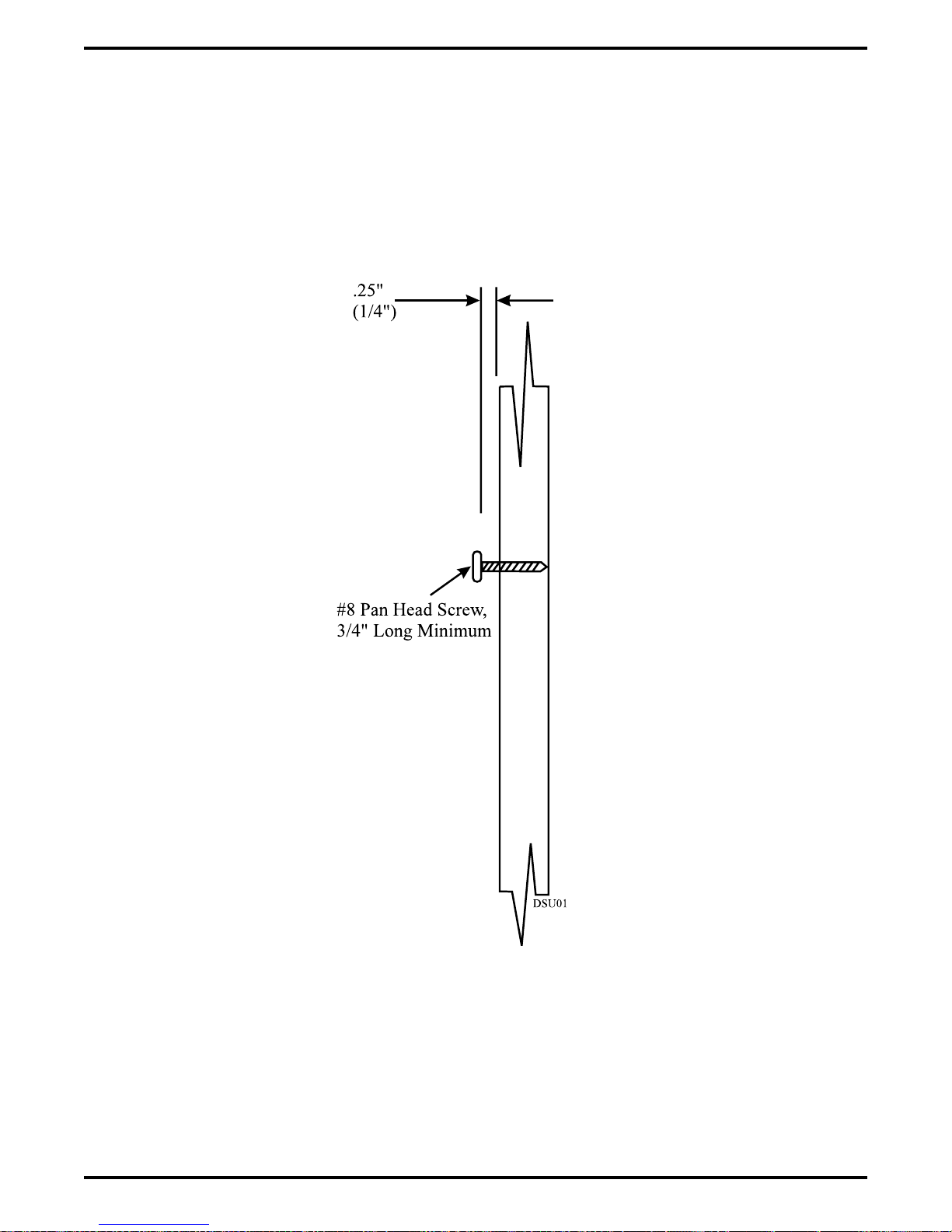
IMI66–107 Digital Telephone System
3. Install two #8 X 3/4-inch screws in the wall at the locations you marked in step 2. Tighten
the screws until the screw heads are 1/4-inch from the surface of the wall.
4. Place the DIU on the wall with the screw heads inserted into the slots provided on the bottom
surface of the DIU. Slide the DIU onto the screw heads until it is firmly attached to the
screws.
Figure 2–32: Installing The Mounting Screws
Installing The DSU 2 – 69
Page 100

Digital Telephone System IMI66–107
Making The Cable Connections
Four cable connections are required to the DIU—station line cord, digital telephone line cord,
IST/FAX/MODEM line cord, and power cable.
1. Disconnect the line cord on the digital telephone from the digital station port connector and
plug it into the connector labeled PHONE on the DIU.
2. Plug the line cord from the IST device you are installing with the DIU (such as a FAX
machine, or modem) into the DIU connector labeled FAX/MODEM.
3. Plug the transformer attached to one end of the power cable into a 115 VAC electrical wall
outlet. Connect the other end of the power cable into the DIU connector labeled POWER.
The green LED on the DIU will be on to indicate power is being supplied to the DIU.
4. Plug one end of a standard line cord into the connector labeled LINE on the DIU. Plug the
other end of the line cord into the digital station port connector.
NOTE: DIU power loss will create the same symptoms as the disconnection of the DIU from
the digital telephone system. If this occurs, plug the multiline digital telephone
directly into a digital station port connector.
Preparing The DSU For DIU Operation
Once you have verified that the system contains the correct software, you must program the
system for DIU operation. See Chapter 4, “System Programming” for programming details.
2 – 70 Installing The DSU
 Loading...