

Page 1

ExecuTech
XE
Key System
System Manual
This publication is applicable for the following common equipment:
NO820
N1024
Rev P and later
Rev P and later
SW release 2.8 and later
SW release 2.8 and later
pKOl2-002
8
IMI
66-097.02
2193
Page 2

IMI
66-097
Table Of Contents
Chapter 1 System Description
Section 1 Technical Documentation For The XE System
Manual Scope
Related Publications
.................................................
.............................................
Section 2 System Specifications For The XE System
Section 3 General information About the XE System
XE System Configuration
...........................................
Common Equipment Description
Description Of XE System Supported Telephones
Description Of The Optional DSS/BLF Console
....................................
.......................................
...............................
...............................
Table of Contents
.........................
...........................
............................
l-1
l-1
l-l
l-l
l-2
1-4
l-4
l-5
1-6
1-6
Chapter 2 Description Of System Features
Chapter 3 Installation
Mounting The System Equipment
Mounting Considerations
installation Notice
Mounting Procedure
........................................
......................................
...........................................
...............................................
.............................................
Connecting The Power And System Grounding
............................
..............................
AC Power Connection
.
BatteryBackUp
System Grounding
Connecting The Outside Lines To The System
Connecting Telephones To The System
Connecting Multiline Telephones
Connecting Single-Line Proprietary Telephones
Connecting industry-standard Telephones
Connecting The Optional DSS/BLF Console
Providing Off-Hook Voice Announce With Handsfree Answerback
Connecting A Power Failure Telephone
Connecting the Common Audible And Auxiliary Station Interface
Connecting The External Paglng Interface At A Station PA Port
Connecting the External Paging Interface At A Line Port
Connecting Equipment At The Auxiliary Equipment Interface
COnneCting
Equipment At The Auxiliary Equipment Interface
Connecting Equipment To The Music Interface
SeCtiOn
2
Checking
Checking
Isolating
Failures
The installation
..::::::::::::::::::::::::::::::::::::::::::::
..............................................
...............................
...................................
.......................................
...............................
..................................
.................................
......................
..................................
(StatIon
17 Audible)
........
....................
........................
......................
......................
..............................
Out The System Installation And Isolating Any Failures
.............
..........................................
...............................................
Section 3 Understanding Installer/User lnformatlon Regarding FCC Rules And Regulatlons
....
.2-l
.3-l
3-l
3-l
3-l
3-2
3-4
;I:
3-4
3-6
3-8
3-8
3-8
3-8
3-8
2-9
3-13
3-14
3-15
3-16
3-17
3-17
3-17
3-18
3-18
3-19
3-20
Chapter 4 System Programming . . . . . . . . . . . . . . . . . . . . . . . . . . . . . . . . . .
Section 1
lntroductlon
To XE System Programming . . . . . . . . . . . . . . . . . . . . . . . . . . . . 4-l
Section 2 Class Of Service Programming . . . . . . . . . . . . . . . . . . . . . . . . . . . . . . . . . . 4-6
Section 3 Attendant Programming . . . . . . . . . . . . . . . . . . . . D . . . . . . . . . . . . . . . . 4-20
Night Transfer (Of Ringing) . . . . . . . . . . . . . . . . . . . . . . . . . .
e e
. . . . 0 . D . . . . 0 . 4-20
Music On Hold
SystemSpeedDialing’:::::::::::::::::::::::::::::::::::::::::::
SystemClock
. . . . . . . . . . . . . . . . . . . . . . . . . . . . a . . . . . . . . . . . . . . . . 0 . - 4-20
. . .
III
.4-l
4-20
4-20
Page 3

Table Of Contents
IMI
66-097
Table Of Contents
Chapter 5 System Operating Procedures
Section 1 Operating
Answering Calls
Making Calls
HoldingCalls
Transferring Outside Calls
Making Conferencing Calls
Using The Message Waiting Light
Blocking Voice Announce Intercom
MonitoringALine
Signalling With Recall Or Flash
Making Page Calls
Engaging The Do
Muting Your Telephone And Inhibiting Handsfree
SwitchingBetweenPulseAndToneDialing
ChoosingPersonalRingingTones
TumingOnBackgroundMusic
Operating
Programming
Section
Setting The System Clock
ProgrammingTheSysternSdeecjcjial.::::::::::::::::::::
Engaging the Night Transfer (of ringing)
Controlling The Music On Hold
Sectlon
Answering Calls Ringing At Your Telephone
Answering Calls Ringing At Another Telephone (Call Pickup Answering)
MakingCalls
Holding Calls
TransferringOuisideealls.::::~:::::::::.::::::::.::‘.:::.:::.::
Making
Using The Message Waiting Light
Making Page Calls
SwitchingBetweenP;lse’AnbidnbDialin~’::::::::::::::::::::::::::::::::
ProgrammingTheStationSpeedDial
Section
Using The Feature Dialing Code Numbering Plan
Setting The Ringer Volume Control
Understanding The Status Indicators And Tone Sequences D .
ASpeakerphone
20peratlng
3
Operating
ConferenceCalls
4
Understanding
-
continued
q
...
MultIline
................................................
.................................................5-l
.................................................
...............................................
Noid&& bdnckoi
AStation
The Attendant Statlon
Single-Llne Telephones
................................................
Telephones
..........................................
........
.............................................................
....................................
......................................
..........................................
............................................
.......................................
..........................................
.....................................
TheSystem
.....................................
..................................
. .
..
Cails’ : : : : : : : : : : : : : : : : : : : : :
.
1 : : 1 : : : : : : 1 : :
Answering
.................................
.................
..................................
...............................
................................
...................................
Operating
........s..
. . . . . . ..... . .
. . .
......................
........................
Characterlstlcs
.............................
....................
a
....D..e.....
..........................................
;
..............
e
...............
................
.................
........
n 0
.
D D s
.
m 0 e s 0 0 D
. .
D D
. . D . 5-13
.5-l
5-l
5-1
5-3
5-4
55-z
5-5
5-6
Z-E
5-6
5-7
5-7
..5..5-
5-8
5-8
5-10
5-10
5-10
5-l
5-10
5-12
5-12
5-12
5-13
5-14
5-14
5-14
g-i:
5-15
5-15
5i6
5-16
5-13
-
-
7
7
0
-
Chapter 6 Maintenance
Technical Assistance And Repair Service
FuseLocation
Wiring . .
. . . . . . . . . . . . . . . . . . . . . . . . . . . . . . . . . . . . . . .
..-.
D e D .*D.....O..s
D o
. . . . s q q q . a .
.....a
0 a
. . m . .
.*
iv
D a
.
e p
.
0 D
. .
a D
q
0 0 0 e D a -6-l
..~....~..6-1
a m s -.* ..- a m..D ..- 0 .* *.. D
6-1
’
6-1
.
Page 4
IMI
66-097
List Of Illustrations
Figure
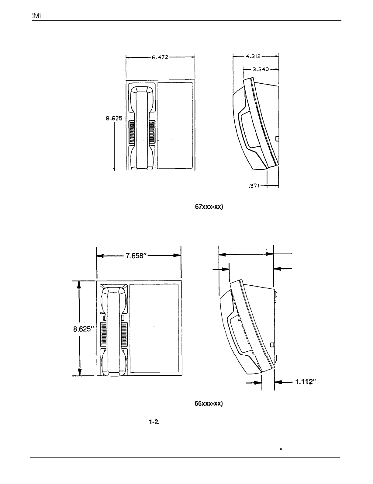
Figure l-2. Station Outline Dimensions
Figure 1-3. Station Images
Figure 3-l. Mounting The Common Equipment
Figure 3-2. Connecting The Power and System Grounding
Figure 3-3. Connecting The Lines
Figure 3-4. Connecting The Telephones
Figure 3-5 Connecting A Secure Off-HookVoice Announce Telephone
.,
Figure 3-6. Connecting A Power Failure Station
Figure 3-7. Connecting The Common Audible and Auxiliary Station Interface
Figure 3-8. Connecting the External Paging Interface At A Station PA Port
Figure 3-9. Connecting The External Paging Interface At A Line Port
Figure 3-10. Connecting Equipment At The Auxiliary Equipment Interface
Figure 3-l 1. Connecting Equipment To The Music Interface
Figure 4-l. Program Button Locations
Figure 4-2. System Programming Block Diagram
Figure 5-l
1-l.
Outline Dimensions - Common Equipment
...............................
....................................
...................................
...............................
................................
.
Controls and Indicators
..................................
...........................
...........................
.......................
.....................
.....................
........................
Table Of Contents
...............
...........
.............
...............
.............
. l-5
. l-7
l-8,1-9
.3-3
.3-5
.3-7
3-11
3-12
3-13
3-14
3-15
.3-l
6
3-17
3-17
.4-3
4-4,4-5
5-l 1
Table 3-l. Line Connections
Table 3-2. Station Connections
Table 3-3. Voltage Measurements
.....................................
....................................
List Of Tables
..................................
.3-6
3-10
3-l
8
Page 5

IMI
66-097
System Description
Cha
System
ter 1
rp
escription
Section 1
Technical Documentation For The XE System
Manual Scope
This publication contains a complete description of the
ExecuTech
multiline and single-line proprietary plus
industry-standard telephone support on certain station
ports. The manual is divided into the following
chapters:
l
System Description
l
Feature Description
0
Installation
l
System Programming
l
System Operation
l
Maintenance
model XE electronic key system with
Related Publications
Related publications that contain additional
information applicable to this electronic key system
are available from the manufacturer and are identified
by the following designations:
General Information
l
IMI
01-005 Handling Of Electrostatically Sensitive
Components
User Information
l
GCA 70-l 10 Attendant Guide
l
GCA
70-l
11 Station User Guide
Installer Information
l
IMI 66-065
Class Of Service Programming Chart
l-l
Page 6
System Description
Section 2
System Specifications
IMI
66-097
SPECIFICATION
SYSTEM CAPACITY
LINES:
STATIONS:
DSS/BLF
INTERCOM PATHS,
MAXIMUM SIMULTANEOUS
INTERCOM CONVERSATIONS:
POWER REQUIREMENTS
(Fully loaded system)
AC POWER:
DIMENSIONS (approximate)
COMMON EQUIPMENT:
WIDTH (inches):
HEIGHT(inches):
DEPTH (inches):
WEIGHT (pounds):
PROPRIETARY STATIONS:
FOOTPRINT (inches):
WEIGHT (pounds):
CONSOLES:
NO820
8
20
10
7
7
117V +/- 10
8A
65W
BOVA
15.750
24.000
3.0
20.5
6.5 x 8.5
1.9
MODEL NUMBER
N1024
10
24
62
8
6
% Singlephase _ all models
STATION CABLE REQUIREMENTS
TYPE:
MAXIMUM LENGTH:
SWITCHING PRINCIPLE:
OPERATING ENVIRONMENT
TEMPERATURE:
HUMIDITY:
TERMINATIONS
LINE:
STATION:
IST PORTS:
Twisted, non-shielded,
1500 feet for proprietary telephones
2000 feet for 1 (or 2 in parallel) model
telephone
Solid-state, space-division analog switching with stored program
control
32-l 22 degrees F (O-50 degrees C)
90 percent relative, non-condensing
Standard, 6-conductor
Standard
distribution field
2 (station ports 26 and 28)
SO-pin female
#24AWG
2500
industry-standard
minijack
connectors for connection to external
(USOC
RJ14C)
Page 7

System Description
MUSIC INTERFACE
IMI
66-097
INPUT LEVEL:
INPUT IMPEDANCE:
CONNECTOR:
CENTRAL OFFICE LIMITS
LOOP LIMITS:
CABLE INSULATION
LEAKAGE:
INDUSTRY/REGULATORY
STANDARDS:
MEMORY RETENTION
AFTER POWER LOSS:
FCC REGISTRATION NUMBER:
RINGER
EQUIVALANCE
NUMBER:
PRODUCT CODE:
NOTE: These product codes become
and K1024 when installers add a
PCCXI conversion kit to them.
KO820
3 Volts peak-to-peak maximum
Approximately 500 Ohms
RCA phono jack
1900 Ohms maximum loop
15000 Ohms minimum
FCC Certified, part 15 (Class A)
FCC registered (fully protected)
Listed by OSHA-accredited, nationally recognized, test laboratory
EIA RS478
Bell publication 48002 guidance
Hearing aid compatible handset
30 hours minimum (typically 200 hours)
CVW7WC12829-KF-E
0.4B
Common Equipment
NO820
N1024
8-line, 20-station
1 O-line, 24-station
ExecuTech Proprietary Telephones
12-line
6700s
6701 X
6702X
6706X
6714s
6714X
LCD speakerphone
single-line
2-line
monitor
6-line
monitor
14-line
speakerphone with SOHVA
14-line
monitor with SOHVA
Optional ExecuTech Proprietary Telephones
6614E
6614T
6620E
6620T
10 x 14 monitor with SOHVA (Rev. D and later)
10 x 14 speaker with SOHVA (Rev C and later)
5 x 20 monitor with SOHVA (Rev D and later)
5 x 20 speaker with SOHVA (Rev I and later)
Industry-Standard Telephones (station ports 26 and 28 only)
Comdial2500
MaxPlus
DSS/BLF
EB32X
DB32S
3879X and 3979X
Consoles
32-button console
32-button console with call announce speaker
LCD Conversion
PCCXI
6600E
Conversion kit
LCD speakerphone with SOHVA (Rev B and later)
Software Upgrade Kit
PSUXIQ
NO820 and
N1024
l-3
Page 8

System Description
Section 3
General Information About the XE System
IMI
66-097
XE System Configuration
The model XE electronic key telephone system
consists of an electronic key service unit
referred to as common equipment, dedicated
electronic telephones, and interconnecting wiring
consisting of small, 4- or 6-conductor, twisted-pair
cable.
The station and line capacity of the XE systems are
per the following chart.
MODEL
NO.
NO820
N1024
The model XE telephone system is full featured, and
supports a specially designed group of multiline and
single-line proprietary telephones (product code series
of
67xxx-xx)
ExecuTech multiline telephones with product codes of:
6614E, 6614T, 6620E, 6620T,
product code
setting may be required to avoid the possibility of a
squeal being sounded through the station speaker
during call announce and/or background music
operations.) Along with the proprietary telephones,
the XE system supports the use of industry-standard
telephones (such as the Comdial2500) at two of its
station ports (ports 26 and 28).
An LCD upgrade kit that includes an integrated circuit
clock is available for the XE system to allow it to
described on page 1-6. It also supports
CO/PBX
CAPACITY
8
10
6414S-xx
6414 and 64148. (If a
is used, a moderate volume
(K&II),
STATION
CAPACITY
20
24
often
support the operation of an ExecuTech LCD
speakerphone (product codes
product code for this LCD upgrade kit is PCCXI. This
kit is available through normal distribution channels for
field installation by trained technicans. The product
code of the XE system changes from Nxxxx to Kxxxx
when the technician installs the LCD upgrade kit. The
new product codes become K0820 and Ml 024.
The LCD speakerphone provides the following feature
displays for the user’s convenience:
Time and Date
Call Duration Time
Do Not Disturb
Line Identification When Chosen Followed By The
Numbers Dialed
Intercom Calling Party Identification
Intercom Number Dialed
Re-display Of Call Time Of Last Call When HOLD
button Is Pressed
A software upgrade kit is available for field installation
by trained technicans. The EPROM chip supplied in
this kit will revise the operating system software of the
XE system to the latest factory issued level. The
product code for the software upgrade kit is:
PSUXI-2 for NO820 and N1024
The software upgrade kit is available through normal
distribution channels.
6700s
or 6600E). The
Page 9

IMI
66-097
System Description
General
lnformafion
About The XE System - continued
Common Equipment Description
The common equipment is a fully electronic device. It
is essentially a special purpose computer system
acting as a communications controller between central
office (CO), private branch exchange (PBX), or
CENTREX
telephone stations. The software architecture of the
supplied lines and the proprietary
common equipment provides complete system
support and great flexibility of operation.
The common equipment is contained in a functional,
modern-style metal housing of contemporary design in
keeping
environment. It is engineered to be wall or rack
mounted. The outline dimensions of the common
equipment cabinet are illustrated in
wtth
the needs of the modem off ice
Figure
1-1.
Figure l-1.
Outllne
Dimensions - Common Equipment
l-5
Page 10

System Description
General Information About The XE System - continued
Description Of XE System
Supported Telephones
The model
microprocessor-controlled devices. They allow not
only multiline pickup but also single button access to
features available from the serving CO, PBX, or
CENTREX
The outline dimensions of the system stations are
illustrated in Figure
in Figure 1-3.
The multiline telephones provide the following features:
Full modular connection
Four fixed feature buttons with indicators
l
. MUTE
. HOLD
.
Two fixed feature buttons without indicators
. TAP
.
Programmable buttons with and without indicators
7-foot,
6-position, 4- or 6-conductor modular line jack
K-type handset (hearing aid compatible)
Ringer volume control (Off, Low, and High)
Desk/wall reversibility
The single-line proprietary telephone provides the
following features:
Standard 3x4 metropolitan dial
Two feature buttons: SHIFT/HOLD, TAP
One status indicator (message waiting light)
Ringer volume control (high/low)
7-foot, 4-conductor line cord
4-position line jack
Desk/wall reversible mounting
The
DSS/BLF
to be a companion to a system attendant station in
high call volume situations that require a dedicated
67xxx-xx
switch as well as the common equipment.
SPKR
ITCM
TRANSCONF
4-conductor line cord
Optional DgS/BLF
telephone stations are electronic,
I-2
and the images are illustrated
Descri
tion Of The
Console
console is an optional device designed
call transfer location. The console provides a direct
station selection (DSS) intercom, and an associated
busy lamp field (BLF). It also provides one-key
access to all-call when that feature is available.
You can install a console at any other station port to
work in conjunction with a companion telephone
connected to the adjacent paired port.
The model
and
DB70-xx
with the XE system. You must program the station port
to which they are connected as a DSS/BLF console
port. The console buttons are fixed for DSS/BLF
operation beginning with station 10 and ending with
the maximum station number in the system: however,
they also provide
of storage (accessed with the HOLD button function).
Additionally, any buttons that are from a number that
is beyond the station capacity of the system through a
maximum of 32 are available as
the first level of storage. For example, a model N1024
key system and a
fix the first 24 console buttons as DSS/BLF buttons,
and provide the remaining eight buttons as
buttons. Plus, it will provide
second level of storage for the first 24 buttons. This
means that it provides a total of 32
locations. For larger consoles, any buttons beyond a
maximum of 32 are blanked. Since the XE system has
a maximum capacity of 24 stations, Comdial does not
recommend the use of the larger consoles such as
DB40 and DB70 because these consoles will show a
large quantity of blanked buttons.
You can use the
provide off-hook voice announce (OHVA) to a station
already busy on a call and allow subsequent
handsfree answerback (HFAB) by that station user.
The
DB32S-xx
console at the same time if desired. You must
program the station port to which the Adjunct Feature
Module is connected to enable the equipment
operation. When your site requires both
OHVA operation, program the station port as an
Off-Hook Call Announce port. When your site requires
only DSS/BLF operation, program the port as a
DSS/BLF Console port.
IMI
66-097
EB32X-xx, DB32-xx, DB32S-xx, DB40-xx
DSS/BLF consoles are all compatible
autodial
EB32X-xx
DB32S-xx
Module can serve as a
locations at a second level
autodial
or
DB32-xx
autodial
Adjunct Feature Module to’
locations at
console will
autodial
locations at the
autodial
storage
DSS/BLF
DSS/BLF
and
1-6
Page 11
IMI
66-097
System Description
8.625
.
(Model Code
67xxx-xx)
4.983”
4.069”
Figure
(Model Code
l-2.
Station Outline Dimensions
Description Of XE System Supported Telephones - continued on next page. , .
66xxx-xx)
l-7
Page 12

System Description
IMI
66-097
14.Line
l&Line
00
00
00
00
00
00
00
00
00
00
00
00
Monitor Telephone
(6714X)
Speakerphone
(67148)
12-Line
LCD Speakerphone
(6700s)
6-Line Mtm~;;xUephone
2.Line
Monitor Telephone
(6702X)
Figure I-3a.
Single-Line Proprietary
Telephone (6701X)
Station
images
(Model Code
67xxx-xx)
I’
DSSlBLF
(EB32X)
I(
Console
Page 13

IMI
66-097
System Description
5 x 20 Image Telephone
(6620E, 662OT)
10 x 14 Image Telephone
(6614E, 6614T)
II
0000000000
II
5 x 14 Image LCD Speakerphone
(SSOOE)
Figure
32.Button
Adjunct Feature Module
l-3b.
Station Images (Model Code
Console
(DB32S)
l-9
‘IO-Button
66xxx-xx)
DSSlBLF
(DB70)
Console
Page 14
Description Of System Features
Description Of
Cha ter2
ystem Features
!i
IMI
66-097
Access Denied
Access to particular lines can be denied at certain stations in the system through system programming.
This feature is programmable on a per line/per station
basis as part of system or administration programming.
Add-On Conference
(2 Internal, 1 External Parties)
This system feature allows a station, while operating in
a private mode, to add another station to an outside
call.
All-Call Paging
(via Station Speakers)
All-call paging allows all of the stations to receive an-
nouncements at the same time through the station
speaker. Origination of announcements must be via a
station handset. Each station can be programmed to
receive and/or to originate an all-call page. The system default condition is that all stations have both
receive and originate capability. The arrangement of
paging as all-call is controlled by both system and administration programming. See the discussion titled
Zone Paging (via Station Speakers).
AlUntercom
Links
Busy Indication
When all intercom paths are busy, the system causes
the intercom light at each station to be on steady.
sertion, Station Speed Dial, and Programmable
DSS/BLE
Auto-Save Feature
The auto-save feature can be
manually dialed number at any unprogrammed button
or at a specific button that was previously reserved for
this purpose. The button chosen for auto-save must be
blank and not currently programmed as a DSS button,
line select button, or auto dial button. An auto-save
can be made at a button previously used as an autosave button; however, the previously stored number
will be over-written. As many manually dialed numbers
can be saved in this manner as there are separate unused buttons to be used for storage. If a dialed number is longer than 15 digits, two or more buttons can
be used to save portions of it for later chain dialing.
used
to save the last
Automatic Abandoned
Hold Release
If a distant party abandons a hold condition and disconnects, the central office (CO) will send a forward
disconnect signal to the telephone system. When the
key system detects this signal, it will drop the line from
the hold condition and return it to service. The
disconnect signal may be either 50 msec. or 350
msec. and the key system is programmable to match
this time interval. Both the system and the administration programming can be used to set the time interval
between hang-up and line-drop.
fonvard
Autodial
Each multiline station provides programmable dialing
features. Programmable buttons can be programmed
to store numbers for automatic dialing purposes. The
stored numbers can be up to fifteen digits in length
and can include line or intercom selection, numbers,
+I+,
pauses, and flash signals. A pause is stored each
time the HOLD button is pressed, and a flash signal is
stored each time the TAP button is pressed. The
pause and flash intervals are programmable. Any
programmable button that does not have a line assignment can be programmed as an auto dial. Additionally, an auto dial number can be stored as a secondary
function at every button programmed for direct station
selection. Often used host PBX or
access codes can be stored at a programmable button
location to provide one-button access to the features.
Also refer to the discussions titled Automatic Pause In-
CENTREX
feature
#,
Automatic Hold Transfer To Intercom
(Answer Hold)
If the intercom line is selected while an outside line
call is active, this system feature causes the outside
call to be automatically placed on hold.
Automatic Pause lnsertlon
When the system stores a dialed number for later
redial,
it automatically stores a pause whenever the
user walts between digits. The automatic pause is in-
serted in the stored number sequence at the point
where the manual pause in dialing occurred. The wait
time is programmable between 2 sec. and 750 msec.
The wait period is programmable by system or ad-
ministration programming.
Page 15
Description Of System Features
IMI
66-097
Automatic Privacy
(Programmable)
A line can be made private or non-private through
class of service programming. In the private mode, a
station has exclusive use of the line during a call. No
other station can access that line unless it is included
through the use of the add-on conference feature. In
the non-private mode, all stations with that line appearance can gain access at the same time (sometimes known as common line pickup). A line
specified as private or non-private through system or
administration programming. Also see the discussion
titled
Add-on Conference And Privacy Release.
Automatic
Redial
(Of Busy
Is
Number Or Unanswered Call)
Automatic redial of the last dialed number can be
made available at every station through button
programming. In most cases, the station user must
program a button for use as an auto redial button; how-
ever, some telephone models provide an Al 6 button
as part of the A-button field and this
redial function as a fixed feature. With this feature, a
busy number or an unanswered call can be redialed
repeatedly. Once automatic redial is activated, the station will select the line, automatically dial the number,
and watt for a response.tt will do this once a minute
for approximately 10 minutes. The user must lii the
handset to take immediate control if the call is com-
pleted. Users of the optional speakerphone station
can take control by pressing the SPKR button instead
of lifting the handset.
provides
an auto
Auxiliary Equipment Interface
A non-key system telephone device or data device can
be connected ahead of the common equipment on certain line ports across the tip and ring leads. Special
terminals in the line jack are provided for this purpose.
The system can detect an off -hook condition in the
connected device, and turn on the line status light at
the key system telephone stations with access to the
line to indicate the busy
condttin.
Auxilia7Station Ringer
nterface
The auxiliary station ringer interface provides ‘dry-con-
tact” relay closures whenever station 19 rings. The
contact closures track the ringing pattern of station
and can be used to control an external
device. When a particular station port is programmed
to function as a PA port, the auxiliary ringer interface
relay contacts automatically become supervisory contacts, They close when the PA port is called In this
configuration, they are used to enable an external PA
sign.alling
17,
system. Also refer to the discussion titled Common
Audible Ringer Interface.
Background Music
If an external music source is provided, background
music can be turned on and off at individual stations.
Background music automatically turns off during calls.
Also refer to the discussion titled External Music
solJtc8~
Basic
The system provides all of the basic,
service features. These features are: selective line
pickup, common line pickup, multiline pickup, and hold.
Key
Senrice (lA2)
lA24ype,
key
Battery Back-Up
(Chassis, Cable, And Batteries)
Battery back-up assemblies including chassis, cable,
and battery are offered as optional kiis (available from
Comdial).
directly to the
terface located on the common equipment chassis.
No user intervention is required with this feature, and
no class of
The assemblies are designed to connect
un-lntertuptable
se&e
programming is required.
power source (UPS) in-
Battery Back-Up interface
Provision has been made for attaching a
provided optional battery back-up kit to give full
unintenuptable
bss. The switching and trickle charge circuitry are in
the common equipment, while batteries, chassis, and
cable are packaged as a separate option. When
plugged into an active AC power source the common .
equipment will constantly charge the attached
t&es
with a trickle current. Built-in circuitry automatically switches to battery power when AC power is
With
batteries at full charge, a fully loaded system will
operate for a minimum of one hour without AC power.
No class of service programming is required.
system power in case of an AC power
Corndial
bat-
lost.
Call Announce With Handsfree
Answerback
The
internat
call-announce capability over the intercom link. A
handsfree response to a call-announce call can be
made. This response is transmitted by the microphone
built into the handset. Also refer to the discussion
titled
speaker at each
Voice
AtVWutE8
Blocking
muttiline
station provides
Call Pickup - Directed
A user at any station can dial a special prefix code, followed by the number of a ringing station, to answer a
ringing call at that station.
Page 16
Description Of System Features
IMI
66-097
Call Pickup - System
A user at any station can dial a special code and
answer a ringing call at any station in the system. The
feature can be enabled or disabled by system or ad-
ministration programming.
Call Transfer - Screened
Screened call transfer allows outside calls to be trans-
ferred from one station to another, via the intercom
link, in one of two ways. If both stations have access
to the line, a common line pickup transfer can be ef-
fected. If the other station does not have access to
the incoming line, transfer can still take place using
the system transfer feature.
call is transferred to another station with a pre-transfer
announcement by the transferring party. Transferring
of calls is accomplished with the T/C (TRANS-
FER/CONFERENCE) button.
For a screened transfer, a
Call Transfer - Unscreened
An active call can be transferred to another station
without being announced. The transferred call will ring
the other station and await an answer. The call will
automatically ring back to the transferring station after
a programmable recall period. A transferred call will
only ring if the station is idle. If the other station is
busy on intercom or is already ringing with another
call, the transferred call will immediately recall the
transferring station. If the other station is idle or has
background music enabled, it will start ringing immediately. If it is in any other state, it will not ring until it
returns to an idle state.
programming is used by the installer to configure the
system and assign the line conditions. Administration
COS programming is used by the on-site administrator
to re-configure the system as required. Line condition
assignment is not a part of administration programming.
Refer to Chapter 4 for programming details.
Common Audible Ringer Interface
Connections are available at the key service unit
which provide “dry-contact” relay closures whenever
an incoming line rings. These contact closures track
the ringing pattern and can be used to control an external signalling device. When a particular station port is
programmed to be a PA port, the common audible
ringer interface contact points automatically become
supervisory contacts which close when the PA port is
called. In this configuration, they are used to enable
an external PA system. Also, see the discussion titled
Auxiliary Station Ringer Interface.
Default Functional Program
At initial power up of the system, the operating features are set to a specific group of operating conditions (default conditions). The default conditions
provide a complete operating system for normal use.
The system can be left as a defaulted system or
operating conditions can be reprogrammed if desired.
A system can be
master clear procedure included with the system class
of service programming: however, this action also
clears all user stored auto dial and speed dial numbers.
defaufted
at any time using the
Calling Station Identification
If the station number of a calling station has been
programmed into the
calling station will be identified by the flashing BLF
light at the called station. The lights adjacent to
programmable buttons indicate status of DSS
telephones: dark = idle, steady-on = in use, and
flash = calling.
Class Of Service
DSS/BLF
of a called station, the
.Programming
(Each Line
And Station)
Each line and station in the system can be
programmed with a unique class of service operating
condition. Class of service programming can be per-
formed using instructions provided in Chapter 4.
Class Of Service Programming (From
Main Station)
Both system and administration class of
programming is performed from station 10 after a base
level programming step is entered. System
service
CCS
(COS)
Delayed Ringing
Refer to the paragraph titled Flexible Ringing Assignments.
Dial 0 For System Attendant
The system attendant station (station 10) is signalled
whenever the digit 0 is dialed on the intercom line.
Direct Station Selection
Intercom
Refer to the discussion titled, Programmable
DSS/BLF.
Distinctive Ringing
The ringing cadence of an incoming call is the same
as the ringing cadence of the TELCO, PBX, or
CENTREX
com call presents two tone bursts sounded every 4
seconds.
system. The
rfnging
cadence of an inter-
2-3
Page 17
Description 01 System Features
IMI
66-097
Do Not Disturb
Any station can be set to a do-not-disturb mode using
the SPKR button. While in this mode, the station will
not ring on any incoming call nor will it accept an intercom call. A party making an intercom call to a station
set in the do-not-disturb mode hears a fast busy tone.
The feature cannot be overridden by the calling party.
DSWBLF
The
DSS/BLF
to any system station. It is useful with high call
volume systems which require a dedicated call transfer location. The console provides a one-button direct
station selection (DSS) intercom and an associated
busy lamp field (BLF). It also provides one-button access to system-wide, all-call paging. The console is
designed to be connected to any station port and
serve as a companion to the station connected to the
adjacent data-paired port. System or administration
programming is used to program a station port as a
DSS/BLF port.
Console is designed to be a companion
Console (Optional)
End To End Signalling
On Intercom
After an intercom call has been established, the sys-
tem can continue to send dialing signals (DTMF tones)
through the intercom path to station ports that are
programmed as OPX unit ports. This feature can be
performed from every station in the system, and is
used by peripherals such as an OPX unit and voice
mail equipment.
End
To;;dS;~alllng
After an outside call has been established, the system
can continue to send dialing signals (DTMF tones)
through the
the distant end for inward call completion (bank by
phone, etc.). This conventional, off-hook dialing fea-
ture can be performed from every station in the system. No class of service programming is required.
telw
network and have them received at
Exclusive Hold
Exclusive hold prohibits a held call from being
retrieved by any other station. The exclusive hold con-
dition also links the held call to the timed hold recall
timeout feature. After timeout, audible and visual
nalling will occur and the exclusive hold condition will
revert to a normal line hold condition. System or administration programming can enable this feature.
sig-
External Paging Interface
A station port or line port can be programmed to inter-
face with an external paging amplifier. The paging
amplifier can then be dial accessed through the station
port or directly accessed through the line port from
other stations in the system.
dialed through the interface to make a zone selection
if zone paging is provided by the external paging
amplifier. System or administration programming can
be employed to program a station port as an external
paging port. Only system class of service programming can be used to program a line port as an external paging port.
DTMF tones can be
Extended Dual Tone Multiple
frequency
The model XE telephone system can access answer-
ing machines, banking computers, voice mail equipment, etc. that require DTMF tones that are longer
than the standard one with a 50 ms. on and off time. A
shift to a longer tone of preprogrammed length is automatically made 10 seconds after a line is selected or
10 seconds after the last digit is dialed. A user can
shit
from one tone length to the other by pressing the
HOLD button and then selecting the line again. While
the off-time of a DTMF tone is maintained at 50 ms,
the class of service programmer can increase the
time 80 ms. so that he or she can program even
longer DTMF tones. Normally a short DTMF tone
gives satafactory results but lf a longer one is needed,
the programmer should choose the one
shortest tone duration that is necessary. DTMF
generation is a system feature and if several stations
are using the extended DTMF feature at the same
time, a delay in the time between button press and
tone sound may be noticed.
(DTMF)
Tones
with
on-
the
’
Flexible Line Assignment
Refer to the discussion titled Square/nor?-Square
tern.
Qs-
Flexible Ringing Assignments
Ringing assignments are programmable on a per sta-
tion/per line basis.
line that has an appearance at each station. Direct, or
immediate, ringing can be programmed for some assigned lines and delayed ringing programmed for
others. Direct or delayed ringing is programmed
through system or administration programming.
Ringing can be controlled for
everyg
Page 18

Description Of System Features
IMI
66-097
Handsfree Answer inhibit
The MUTE button on a
block all handsfree answerback response. This arrangement will prevent a station user from monitoring
another station site using the monitoring ability of the
voice announce feature.
all handsfree answerback is disabled thus inhibiting
any off -site monitoring.
indicate that this feature is active. Also refer to the discussion titled Mute.
multiline
The speaker light will flash to
station can be used to
When the button is pressed,
Headset interface
A station port can be programmed to allow the operation of special telephones which provide the user with
a headset option. Programming for this feature is
through either system or administration programming.
Hearing Aid Compatible Handset
The station handset is compatible with
coupled hearing aids.
magnetically-
idle Line Preference
The system can be programmed on a per station basis
to enable idle line preference. When idle line
preference is enabled, taking the handset off-hook will
automatically connect the station to any assigned line
that is idle and has been arranged for this feature.
The line button will not have to be pressed. This feature is mutually exclusive with prime line automatic.
Programming for this feature is through either system
or administration programming.
ing and releasing, or flashing, the hookswitch (or by
pressing the TAP button if the telephone includes
one). If he or she dials no digits after taking the
telephone off-hook, the system drops the outside line
when the user flashes the hookswitch; however, if the
user dials digits after taking the telephone off-hook,
the system places the outside line on hold when the
user flashes the hookswitch. The class of service
programmer must designate the two station ports as
OPX ports to support the operation of industry-standard telephones.
intercom Call Progress Tones
Intercom call progress is marked by special tones.
A steady tone is provided for dial tone.
nalled intercom calls, a two-tone burst is sounded
every four seconds at a called station and returned to
the caller as ring-back. For a voice signalled intercom
call, a single tone burst is sounded at a called station
and returned to the caller as ring-back. When a called
station is busy on an outside call, the feed-back supplied to the caller is programmable with class of service programming. This feed-back can be either a
ring-back tone or a busy tone. When set for ring-back
tone, the called station sounds subdued ringing during
the call. When a called station is busy on the intercom, a busy signal of one tone burst sounded each
second returns to the calling station.
For tone
sig-
intercom Line Lockout .
Refer to the discussion titled Voice Announce
Blocking.
i Hold And I Use indications
The light associated with a line button provides a
visual indication of the status of that line. When a station user has a line in-use or on-hold at a station, the
light indication provided at that station is of a different
flash rate than the indication provided at the other stations in the system.
industry-Standard Telephone
The XE system supports an industry-standard
telephone on station ports 26 and 26.
standard telephone provides its user with outside line
access and basic intercom service plus access to system features through special dialing codes. At
the telephone provides intercom line access when the
user takes it off-hook. With either prime line alone or
prime line and idle line preference enabled through
programming, the industry-standard telephone
provides an outside line when the user takes it
hook. After going off-hook and receiving outside line
dial tone, the user can get the intercom line by
The’industry-
defautt,
off-
press-
intercom Line Timeout
Should the intercom line be selected with no dialing or
other action taking place, the intercom will timeout
after ten seconds, and return to an idle state.
Last Number Redial
Each station is provided with a last number redial fea-
ture. This feature will save thirty
side number dialed. A newly dialed number will
always automatically replace a previously dialed num-
ber. Upon command, the system will choose a line
and redial the saved number. The system will first
choose the prime line if assigned and idle. If it is busy
or unavailable, the system will choose any line as-
signed to idle line preference. If they are unavailable,
the system will chose the last line used at the station.
If it is busy, no further choice is made. Also refer to
the discussion titled Automatic Pause Insertion.
dig&
of the last out-
2-5
Page 19

Description Of System Features
IMI
66-097
LCD Support
The common equipment can be field modified with an
optional up-grade kit which allow the system to support the use of LCD speakerphones having a Liquid
Crystal Display (LCD). The LCD speakerphone ports
are identified by system or administration programming.
When a system is modified, the model code of ft is
changed from an N prefix to a K prefix (that is
IST becomes
K1024-IST
for example).
N1024-
Line Preselection
A line can be manually selected before lifting the handset (for handsfree dialing) or after the handset is lifted.
Line Type
A line port is programmed as to type. The program
type is chosen based upon the toll restriction that is to
be applied to calls made over the line connected to
that port. A line port is assigned as type 1 when any
enabled toll restriction is to be applied with the first
digit dialed. Such a line type is often assigned when a
CO line is connected. A line port is assigned as type 2
when any enabled toll restriction is to be applied begin-
ning with the second digit dialed. Such a line type is
often assigned when a PBX or
any trunk access code is connected. A line port is assigned as type 3 when any enabled toll restriction is to
be applied beginning with the second digit dialed
whenever the first digit is a 9. If the first digit is not a
9, no restriction is applied. Such a line type is often as-
signed when a PBX or
cess code of 9 is connected. Line types can only be
selected as part of system class of service program-
ming.
CENTREX
CENTREX
line with a trunk ac-
line
with
Manual Hold
A button activated feature at each station will place an
outside line on hold. Pressing the HOLD button holds
the call, provides a distinctive flash rate of the line button indicator, and allows the user to access other station features. The holding station or any other station
which has access to the line can retrieve the held call.
Memory Retention Without Batteries
Independent of the optional battery pack, the system
memory is electronically protected during AC power
failures by an electronic component sometimes
referred to as a “super-cap”. The stored program data
will remain in memory for a minimum of 30 hours
provided that the system has been powered continuously for at least 30 minutes prior to the power
failure or disconnection.
Message Waiting
Special dialing codes enable a station user to control
the message waiting (MW) light at other stations in the
system. When the message waiting light is turned on
at a station, a call can be placed to the originating station to pick up the message.
Modular Wiring And Jacks
4-Conductor
The system
employing industry standard 50-pln connectors and
modular plug/jack combinations. Station wiring is
small, 4-conductor, twisted-pair cable throughout the
system.
can
be completely interconnected by
Wire System
Momentary Buttons With LED
Indicators
The station buttons are momentary contact, press and
release types. They provide line selection, call
monitoring, and other feature selection.
tion of the feature selection is provided by solid-state,
long-life, light emitting diodes
(LEDs).
Visual indica-
Multiline Conferencing
This feature will allow one or more multiline stations to
access two outside lines at the same time resulting in
a conference arrangement. Conference transmission
levels are not compensated.
Music Interface (External Source)
A jack is provided on the common equipment for the
connection of a customer-provided KX registered
music source. Also refer to the discussions titled Back-
ground Music and Music-on-hold.
Music-On-Hold
Music is provided to outside lines that are placed on
hold if an external music source is connected to the
system and the feature is turned on from station
System, administration, or attendant programming can
be used to program this feature.
10.
Music-On-Hold System-Wide
Enable/Dis.able
Music is provided to outside lines that are placed on
hold ff an external music source is connected to the
system. Music-on-hold can be disabled system-wide
by attendant action. Attendant programming is used
to enable/disable this feature. Also refer to the discussions titled: Music Interface, and Music-on-hold.
Page 20

Description Cf System Features
IMI
66-097
Mute
Each station has a MUTE button which, when
pressed, will mute the handset transmitter (or internal
microphone on speakerphones) to prevent the user’s
voice from being heard by the distant party. The
speaker light flashes to indicate a muted condition.
The button provides push-on/push-off operation. Also
refer to the discussion titled
Han&free
Answer Inhibit.
Night Transfer (Of Ringing)
The day, or normal, ringing of incoming lines can be
transferred to a particular station or stations (chosen
through class of service programming) for off-hour or
special purpose answering. The night transfer mode
can only be activated from station 10. Night transfer
of ringing can be assigned to specific stations using
system or administration programming. It is then
turned on or off by using system or administration as
well as attendant class of service programming.
Off-Hook Voice Announce
With Handsfree Answerback
With the off-hook voice announce (OHVA) feature, an
announcement can be made from one station to
another station that is busy on a call. The OHVA an-
nouncement is made in a manner that permits the dis-
tant on-line party to hear it and to hear the verbal
response to it unless action is taken with the MUTE
button. The OHVA feature is available at stations that
are equipped with a multiline telephone and an adjunct
feature module (32-button DSS/BLF console with call-
announce).
Two data-paired stat/on
pofts
are re-
quired to provide OHVA operation,
An OHVA call is preceded by a ring burst. Then,
several quick tone bursts followed by the an-
nouncement are delivered through the loudspeaker in
the adjunct feature module. The called party can verbally reply to an OHVA call in a handsfree manner
without interrupting the active call. Reply is made by
speaking toward the OHVA microphone included in the
adjunct feature module. The distant on-line party can
hear this response unless the MUTE button is pressed
at the called station to mute the handset transmitter.
A station that has the voice announce blocking feature
turned on cannot receive an OHVA call.
Station class of service programming is used to program a station port to be a multiline telephone port
and the data-paired port to be a console with
nounce port. Also refer to the discussion titled: Secure
Off-Hook Voice Announce.
calf
an-
On-Hook Dialing
Every
muttiline
matic dialing while the station handset is on-hook. An
station provides manual and/or auto-
internal speaker monitors call progress for completion.
The handset must be taken off-hook to provide the
voice link on non-speakerphone stations.
OPX
support
The system supports the operation of the optional off
premises extension (OPX)
tion programming arranges a station port for OPX
operation.
A telephony device that is connected through an OPX
unit to a station port has access to both outside line ac-
cess and basic intercom service plus access to system features through special dialing codes. The
system default provides intercom line access when the
device goes off-hook.
prime line and idle line preference enabled through
programming, the device will seize an outside line
when it goes off -hook.
can obtain the intercom line by generating a flash sig-
nal. If it does this before tt generates any DTMF
codes, the system drops the outside line when
detects the flash signal. If the device generates any
DTMF tones before it generates a flash signal, the system places the outside line on hold when it detects the
flash signal.
unit.
System or administra-
Wth
either prime line alone or
After going off -hook, the device
it
Originating Denied
The ability to originate calls on certain lines can be
denied at individual stations through system program-
ming. The originating denied feature is programmed
on a per station/per line basis. Originating denied
does not prevent a user from answering a ringing line,
retrieving a held call or receiving a transferred call.
Call origination on a line is denied at a particular station by the system or administration programming.
PBXICENTREXICentral
Office
.
Compatible
System features and programmable buttons support
the requirements of most
CENTREX
mable pauses, and flash signals can be made a part
of every stored number for access to host system feature codes.
systems. Numbers,
PBXs,
Central Offices, and
#‘s, %‘s,
program
Personalized Ringing Tone
This programmable feature enables stations to ring in
a distinctive manner with one of four different tones.
The ringing tones are combinations of four different frequencies and two
ing tones can be assigned with system or
administration programming.
different
warble rates. Personal ring-
2-7
Page 21
Description 01 System Features
IMI
66-097
Power Failure Transfer
A power failure line connection is available for installing an industry-standard telephone such as a Comdial
model
automatically connected directly across line 1 by the
system whenever there is an AC power failure. Normal origination and reception of calls through the
power-fail telephone is possible during an AC power
failure. The power-fail telephone is automatically dis-
connected as soon as power is restored.
2500-xx.
The installed power-fail telephone is
Power On, Visual Indication
The common equipment has a red LED which
monitors the status of the system, and provides an
“AC power-on” indication.
Prime Line Automatic
If a station is programmed for prime line automatic, the
designated outside line or intercom line will be auto-
matically selected when the handset is taken off hook.
Prime line pick up may be pre-empted by preselecting
another line before lifting the handset. If the prime line
is ringing, it is automatically answered by lifting the
handset. Assign a prime line to a station through sys-
tem or administration programming.
Privacy Release
A line can be made non-private at a particular station
while remaining private at all other stations. This ar-
rangement allows other stations with that line appearance to join that particular station whenever it is
on the privacy-released line. A line is specified as
private or non-private at a particular station with system or administration programming. Also see the discussions titled Add-on Conference and Automatic
Privacy.
visual indicators of the stations programmed at the button locations form a busy lamp field (BLF). The BLF
conveys station status to the user. An auto dial number can also be programmed as a secondary function
at every
discussions titled Tone Or Voice
and Auto Dial.
DSS/BLF
memory location. Also refer to the
S&na//ing
(Intercom)
Pull Out Directory
Each desk mounted telephone is equipped with a pull
out directory. This directory can be used for recording
the system speed dial, station speed dial, or other frequently called numbers.
Pulse/Tone Switchable
When rotary dial lines are installed, the user can
switch from pulse (rotary dial signals) to tone (Dual
Tone Multiple Frequency signals - DTMF). This feature is useful for accessing special circuits requiring
DTMF tones such as banking machines, etc. The system is programmed on a per line basis to allow this
feature at all stations. The system or administration
class of service programming enables this feature on
a per line basis.
Ringing Line Preference
The system can be programmed on a per station basis
to provide ringing line preference on all lines
programmed for ringing at a station.
When ringing line preference is enabled at a station,
taking the station off-hook automatically connects it to
any outside line which happens to be ringing at the station. A line button will not have to be pressed. The
ability of a particular station to answer a ringing line
without line selection is enabled by the system or ad-
ministration class of service programming.
Programmable Buttons
All multiline telephones are equipped with a minimum
of twelve programmable buttons which can be
programmed a line pick-up, auto dial, station speed
dial,
and’DSS
Auto Dial, Programmable DSS, And Station Speed
Dial. System or administration programming is used to
assign functions to programmable buttons.
action. Refer to the discussions titled
Programmable DSS/BLF
(Direct Station Selection/Busy Lamp Field)
A multiline station user can store true, one-button,
direct station selection (DSS) at any programmable
button location to create a DSS button. When this but-
ton is pressed, any active outside call is automatically
placed on hold and an intercom call is automatically
made to that previously stored station number. The
Secure Off-Hook Voice Announce
With the secure off-hook voice announce (SOHVA) feature, an announcement can be made from one station
to another station that is off-hook and busy on a call.
The SOHVA announcement is made in a manner that
prevents the distant on-line party from hearing tt or
from hearing the verbal response to it because the
MUTE button must be pressed for reply. The SOHVA
feature is available at stations that are equipped
telephone that includes SOHVA capability.
telephone requires two data-paired station ports to
provide SOHVA
make secure off-hook voice announcements to busy
stations and then transfer calls to them after making
the announcement if they wish. The transferred calls
camp-on at the busy stations and wait to be answered.
To do this, a user performs a normal screened call
transfer procedure but uses the SOHVA method to
operation.
Telephone users can
The
with
an-
a
Page 22

Descriotion
Of Svstem Features
IMI
66-097
nounce
ferred call automatically camps-on at the busy station.
A SOHVA call is preceded by a ring burst. Several
quick tone bursts, followed by the announcement, are
then delivered through the handset receiver of the
telephone. Delivering the announcement in this man-
ner prevents the distant party from hearing it. A station
employing a speakerphone being operated in a
sfree mode will receive a ring burst and its user can
then take it off-hook to receive the SOHVA call. The an-
nouncing caller receives several tone bursts to alert
them that they are making a SOHVA call and that they
may not get a reply should the called party choose to
not respond.
The user responds to the SOHVA call by pressing and
holding the MUTE button and speaking into the
telephone handset. Because the MUTE button is
pressed, the distant party is prevented from hearing
the response.
The system provides SOHVA operation at every sta-
tion port; however, a station that has the voice an-
nounce blocking feature turned on cannot receive a
SOHVA call. Also, on headset equipped telephones,
the telephone headset cannot be used to receive a
SOHVA call.
Station class of service programming is used to program a station port to be a multiline telephone port
and the data-paired port as a console with call an-
nounce port. Also refer to the discussion titled:
Hook Voice Announce with Handsfree Answerback
and to the Chapter 3 paragraph titled Secure Off-Hook
the call. When he or she does this, the trans-
hand-
off-
Voice Announce Station.
Secure Off-Hook Voice Announce
(SOHVA) Groups
The ability to receive and originate SOHVA and OHVA
calls is provided to every station in the system. Any
station in the system can send a SOHVA or OHVA call
to any other SOHVA or OHVA-equipped station in the
system. Through this feature, the ability of a station to
receive and/or originate SOHVA or OHVA calls can be
disabled through programming so that certain stations
can be grouped together for SOHVA or OHVA calling
between one another while other stations in the system are excluded from this group. Stations can be ar-
ranged in up to four difl erent groups for exclusive
SOHVA or OHVA calling. For example, the stations of
an executive and an assistant can be arranged into
the same group as follows: Program the executive’s
station for receive in group 1 and program the
assistant’s station for originate in group 1. Do not pro-
gram any other stations to have receive or originate
capability in group 1. This arrangement provides exclusive SOHVA or OHVA calling between the two stations. More executive stations can be programmed to
have receive capability in group 1 thus giving the assistant the ability to make SOHVA or OHVA calls to them
as well. These executive stations in group 1 cannot
make SOHVA or OHVA calls to one another, however,
since they do not have originate capability.
of service and administration programming can be
used to form SOHVA groups.
sion titled Secure Off-Hook Voice Announce and
Hook Voice Announce with Handsfree
Each station can execute a self test when so enabled.
This test verifies processor, indicator, and tone func-
tions. Instructions for activating self diagnostics are
provided in Chapter 3, Section 3 of this publication.
Refer to the discussion titled System Speed Dial.
The XE system supports a proprietary single-line
telephone on every station port except port 10. The
single-line proprietary telephone provides its user with
outside line access and basic intercom service plus ac-
cess to system features through special dialing codes.
At default, the telephone provides intercom line ac-
cess when the user takes it off-hook. With either
prime line alone or prime line and idle line preference
enabled through programming, the single-line
proprietary telephone provides an outside line when
the user takes it off-hook. After going off-hook and
receiving outside line dial tone, the user can get the in-
tercom line by pressing the TAP button. If he or she
dials no digits after taking the telephone off -hook, the
system drops the outside line when the user presses
the TAP button; however, if the user dials digits after
taking the telephone off-hook, the system places the
outside line on hold when the user presses the TAP
button. The class of service programmer must pro-
gram a station
telephone if he or she wishes it to do so.
The optional speakerphone provides handsfree opera-
tion of all features, except voice signalled intercom
calls. The handset must be lifted for this purpose.
Both class
Also refer to the discus-
Answerback.
Self Diagnostics
Single-Digit Station Dialing
Single-Line Proprietary
Telephone Support
port
to support a single-line proprietary
Speakerphone (Optional)
Off-
s
2-9
Page 23
Description Of System Features
IMI
66-097
Square/Non-Square System
(Button Mapplng)
A system can be programmed to be square or
square as desired. In a square system, a specific line
is assigned to the same button on every station in the
system. In a non-square system, any line can be assigned to any available programmable button on every
station in the system. Also refer to the discussion
titled Tenant Service. Button mapping for line ap-
pearance can be
system or administration class of service programming.
periormed
on each station using the
non-
Station By Station Privacy
Refer to the discussions titled Automatic Privacy and
Privacy Release.
Station Speed Dial
Each station can be programmed to provide ten speed
dial numbers at the keypad buttons. Station speed
dial numbers can be up to fifteen digits in length and
can include line or intercom selection, numbers, #,
pauses, and flash signals. A pause is stored each
time the HOLD button is pressed, and a flash signal is
stored each time the RECALL button is pressed.
*,
parameters assigned at a station will be overridden
when a system speed dial number is called. With over-
ride disabled, toll restrictions assigned at a station will
prevent it from calling a system speed dial number
that matches the restrictions. Class of service
programming or Administration programming can be
used to enable or disable this feature.
discussions titled System Speed Dial and Toll Restric-
tion - Flexible.
Refer to the
Subdued Ringing
Subdued ringing is automatic at any station that is
busy on an outside line,
Tap (Flash/Recall)
When host system custom calling features are available via a “flash” signal, the system can be
programmed so that the TAP button will generate a
“flash” signal when it is pressed. When custom calling
features are not available, the TAP button functions as
a positive disconnect or dial tone recall button. These
two features are mutually exclusive. The flash/recall
time is assigned through system or administration
programming.
System Speed Dial
Thirty, system-wide, speed dial numbers are provided.
The system speed dial numbers can be up to fifteen
digits in length, and can include numbers,
pauses, and flash signals. System speed dial number
programming can only be performed at station 10;
however, once programmed, they can be used at
every station in the system. System, administration,
or attendant programming can be used to program sys-
tem speed dial numbers.
#‘s, +‘s,
SLstem Speed Dial Toll
estrictlon
This feature makes it possible to override toll restric-
tion parameters when a system speed dial number is
dialed. With it, it is possible to use toll restriction
tables to restrict calls from being made to certain toll
areas yet allow specific numbers in the restricted
areas to be called by storing them as system speed
dial numbers. With override enabled, toll restriction
Override
Tenant Service
Two or more closely located sites can simultaneously
be served by the same common equipment. Each site
is provided with dedicated trunk facilities and separate
feature and class of service complements. Also, refer
to the discussion titled Square/Non-Square
Button mapping for line appearance can be performed
on each station using the system or administration
programming.
Sysfem.
Timed Hold Recall
After a call has been on hold for a programmed length
of time, the system will recall the station that placed
the call on hold. It also visually signals all other stations. The audible signal is repeated at the end of
each reoccurring time out period. The visual indication
continues until the held call is picked up. The system
or administration programming sets the timed hold
recall time period.
Page 24

Description Of System Features
IMI
66-097
Toll Restriction - Flexible
Flexible toll restriction can be programmed to prohibit
some or all stations from calling a wide range of number combinations while allowing specific exceptions.
Restrictions are specified by up to four entries on a
deny table while exceptions are specified by up to four
entries on an allow table. Allow entries will always
override deny entries. Up to eight digits are permitted
for each entry. A “match anything” digit (# symbol) can
be included as
from 1 to 0. This is used to deny or allow a range of
numbers with one entry. A separate pre-programmed
1+800
allow table permits this dialing feature to be
selected regardless of any restrictions which may be
specified. The dialing of 911 and
lowed.
Once programmed, flexible toll restriction is assigned
on a per line/per station basis. In addition to flexible
restriction, or as an alternative to it, stations can be
restricted with l/O call restriction assignment. When
l/O call restriction is selected, 1+ 7 digit dialing can be
allowed if desired. Either system or administration
programming is used to specify the deny and allow
entries and assign the restriction to line and station.
pari
of an entry to represent any digit
1+911
is always al-
Tone Or Voice Signalling
(Intercom)
Intercom calls can be tone signalled or voice signalled
as desired. The tone signalled intercom call must be
answered by lifting the handset. The voice signalled
intercom call can be responded to in a handsfree man-
ner. The class of service programming determines
which signalling method is employed as the primary
method when an intercom call is made. The alternate
method is available through user action at the station.
Intercom call progress is marked by special tone signals. The system or administration programming
determines which type of intercom signalling is first option signalling for the system. Also refer to the discussions titled Intercom Call Progress Tones and Voice
Announce Blocking.
Voice Announce Blocking
This feature allows the user to block voice announced
intercom signalling by dialing a special code. This fea-
ture, when enabled, also blocks the reception of a
SOHVA call.
Zone Paglng (Through Station Speakers)
Zone paging allows groups of stations to receive announcements through the station speakers. The
programming can enable zone paging in up to three
different zones. A station can be programmed to only
receive announcements or programmed to originate
announcements as well. Each station can be
programmed to be in any or all zones for both receiving and originating announcements. The ability of
each station to originate and/or receive a page, and
the arrangement of the paging into different zones are
controlled by system or administration programming.
Also, refer to the discussion titled
Station Speakers).
AI/-Call
Paging (via
Page 25

IMI
66-097
Cha ter 3
lnsta lation
7
Mounting The System Equipment
Installation
Mounting Considerations
Attach the common equipment cabinet vertically to
any sturdy, flat, surface or vertically rack mounted if
desired.
Locate the cabinet within four (4) feet of a proper
electrical outlet. The system requires a dedicated
117VAC
supplied to a standard electrical outlet (NEMA
515R).
The distance between the common equipment and
the TELCO/PBX jacks must be 25 feet or less as
per FCC requirements. A nominal distance of 7 feet
is recommended.
The mounting location must be secure and dry and
have adequate ventilation. The temperature range
of the location must be within
(O-50 degrees C), and the relative humidity must be
less than 90 percent non-condensing.
If the mounting surface is damp or if it is concrete or
masonry material, you must attach a backboard to
the mounting surface to be used for common
equipment mounting. Suitable mounting
backboards are available commercially or can
construct one out of
Tools and hardware required:
15 AMP circuit, with a third-wire ground,
i/2-inch
32-122
plywood cut to size.
degrees F
Fasteners - wood screws
head), toggle bolts, or wall anchors
Screwdriver-to match fasteners
Electric drill - if prepared holes are required
Connecting tool - for fastening wires to a type-66
connector block.
Crimping tool - for 623-type modular plugs.
(l/4
x l-inch round
Installation Notice
Per The Underwriters Laboratories regulation 1459,
2nd edition, be aware of the following precautions
when installing telephone equipment that is to be
directly connected to the telephone company network:
Never install telephone wiring during a lightning
storm.
Never install telephone jacks in wet locations unless
the jack is specifically designed for wet locations.
Never touch uninsulated telephone wires or
terminals unless the telephone line has been
disconnected at the network interface.
Use caution when installing or modifying telephone
lines.
3-1
Page 26
Installation
IMI
66-097
Mounting Procedure
1.
Unpack, and carefully inspect the common
equipment and telephones for shipping damage.
Notify the shipper immediately of any damages
found. Verify that the packages contain all parts
and accessories needed for proper installation and
operation.
2.
If a backboard is required at the mounting location,
attach it securely to provide a stable mounting
surface for the equipment.
3.
Attach the common equipment with three screws
that you thread into three mounting holes located
as shown on
3-l
(
measure and mark the location of the mounting
holes on the mounting surface.
4.
Drill holes in the mounting surface of a proper size
to accommodate the hardware being used. If
Flgure
3-l.
While referring to
Flgure
necessary, prepare these holes with inserts,
anchors or other attachment devices as dictated by
the type of mounting surface.
5. Insert the top screws into the mounting surface,
and tighten them to within approximately
the surface.
6.
Hang,the
mounting holes located on the rear of the cabinet.
Note that these holes are elongated with an
enlargement at one end. This feature allows the
cabinet to slide down on the screws to secure the
mounting when the cabinet is hung on them.
7.
insert
located on the lower edge of the cabinet and into
the mounting surface, and tighten it into place
cabinet on the top screws using the
a third screw through the mounting tab
i/&inch
of
Page 27

14.000
t-15.75o
MODELS
NO820
N1024
K0820
K1024
OUTLINE DIMENSIONS
3.000
24.000
MOUNTING DIMENSIONS
1
22.750
+
Figure
3-l.
Mountlng The Common Equipment
Page 28

Installation
Connecting The Power And System Grounding
AC Power Connection
Employ a dedicated
third-wire ground, supplied to a standard
outlet (NEMA
A plug-in power line surge protector should be
installed between the power cord and the AC outlet.
Do not connect the AC power cord until the
installation has been checked.
To apply AC power, connect the power cord to the
electrical outlet.
5-15R)
117VAC
for the AC power connection.
15 AMP circuit, with a
electrical
Battery Back-Up
The common equipment provides an interface
connector for the connection of an optional external
battery assembly. This assembly is available
separately as a kii.
Be sure that the AC power cord Is
connected to the electrlcal outlet before
connecting the external battery assembly
to the common equlpment Interface
connector. This ensures that Internal
protectlon clrcuttry Is operatlng to prevent
damage
connectlon.
When charged to full potential, the optional Comdial
model BBUOl external battery assembly provides a
minimum of one hour of operation should the AC
power to the system be interrupted. No calls will be
dropped when an AC power failure causes the
system to automatically switch over to
operation
The BBUOl external battery assembly may include
batteries from either of the following suppliers:
-
Model PS-1265 from Power-Sonic Corporation,
Redwood City CA, 94032.
-
Model
Santa Anna, CA 92704
During AC operation, the common equipment
provides recharging current to maintain the voltage
potential of the external battery assembly at an
operational level.
that could result from improper
BBUOI
EP1265-26
from Elpower Corporation,
IMI
66-097
NOTE: The optional external battery assembly
requires approximately 24 hours to completely
re-charge to
completely discharged and, in some cases,
when initially installed. The charging circuit
may not provide an adequate charge if an
installed battery assembly has a current rating
of greater than 15 ampere-hours-
The BBUOl
ampere-hour current rating and provides an absolute
minimum of one hour of operation should the AC
power to a system be interrupted. Calculate the actual
minimum battery back-up time for any configured
system using the following formula:
T=
1
T =
Back-up time in hours
K =
0.9
e
= Ampere-hour capacity of battery (BBUOl = 6.5)
N
= total number of stations
Examples:
N0820-IST, K0820-IST
(Kj
+
I(O.1) (WI
ex-ternat
T=m
1 4
[(O.l) (20)]
N1024-IST, K1024-IST
(0 9ll6.51
T
= 1 4
iiO.1) (24)]
full
potential after it has been
battery assembly has a 6.5
le1
q
.
=a
3.4
+=!.%t-iOUrS
=
1.72
Wours
System Grounding
The common equipment cabinet has internal
secondary surge protection on all line ports. In order
for this protection to be effective, you
the cabinet to a reliable earth ground such as a metal
cold water pipe or a building frame ground. The
grounding wire must be of
copper and separate from the three-wire AC line cord.
The common equipment cabinet provides a ground
stud for this purpose.
#lO
or
MUST
#12
insulated, solid
connect
Page 29
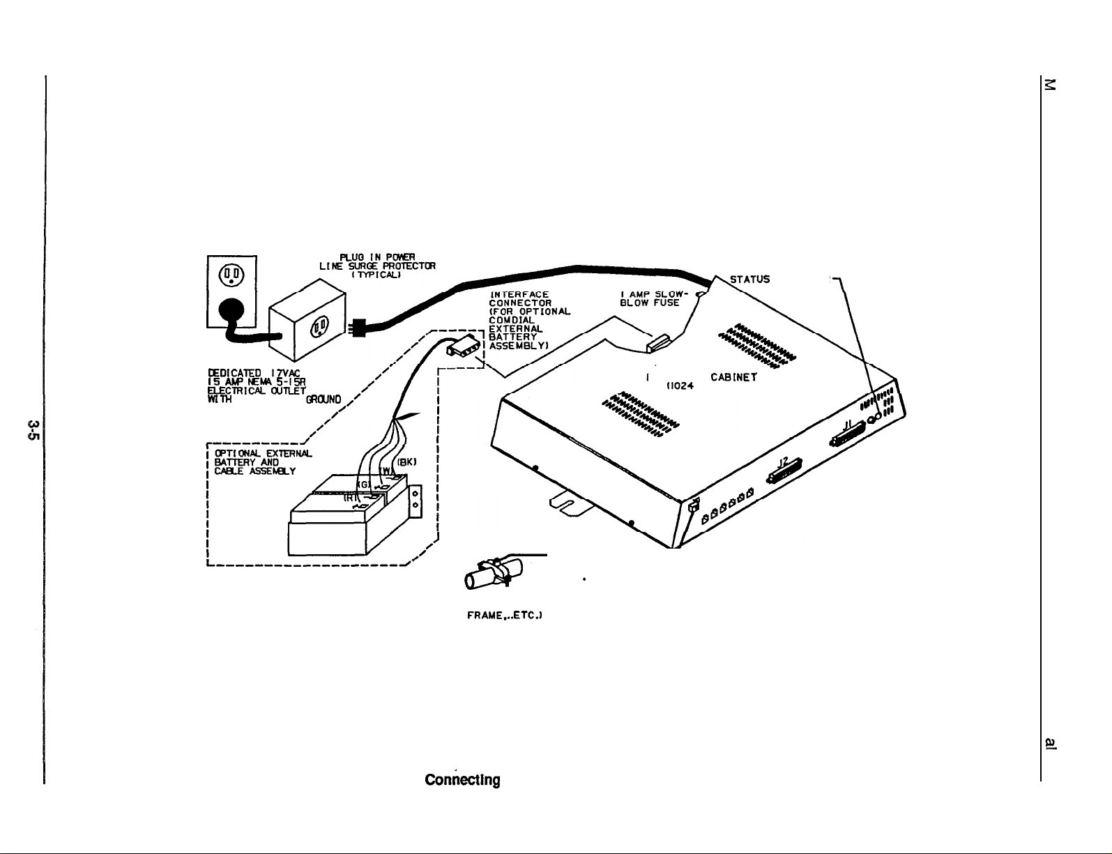
5
INDICATOR
OEDICATED
I5 Aw EM 5-I!3
ELEClRlW alnET
WITH
---,---,,I
I
17VAc
THIRD-WIRE
GROUND /’
0
,//
/J
m
TYPICAL EARTH GROUND
(METAL COLD WATER PIPE.
BUILDING
FRAME...ETC.)
GROUNDING TERMINAL=
*
TYPICAL COMMON
EQUIPMENT
(1024
CABlNET
SHOWN1
Figure 3-2.
Contkctlng
The Power and System Grounding
Page 30
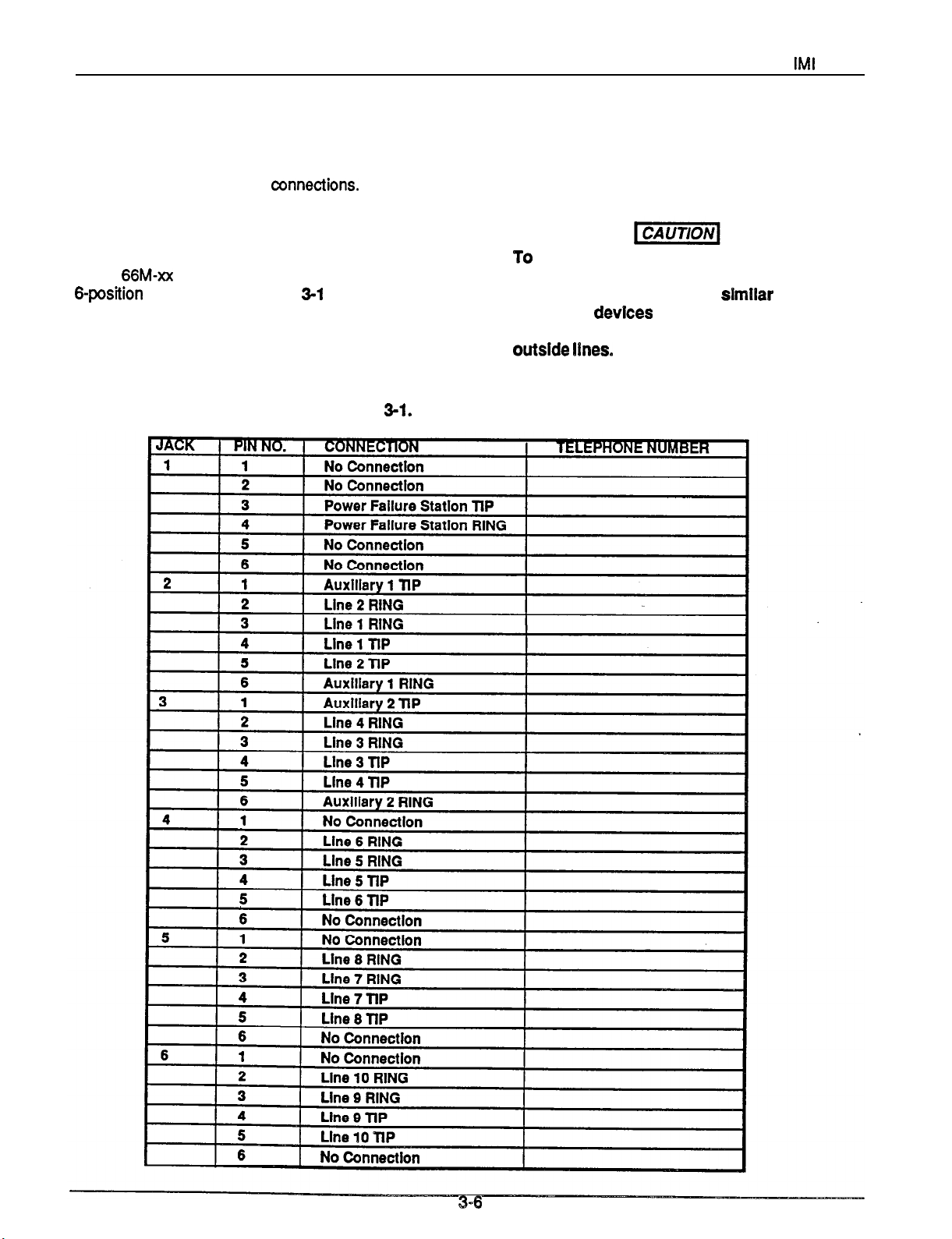
Installation
Connecting The Outside Lines To The System
MI
66497
The common equipment cabinet line terminations are
standard modular plug/jack
modular jack (2-6) provides termination for two lines.
Modular jacks 2 and 3 also provide termination for an
auxiliary pair in addition to the two outside lines. Line
terminations at the demarcation point can either be at
a type
connection details.
The tine cord that is routed between the CO line
termination and the common equipment cabinet
termination should be twisted-pair wiring.
66M-xx
6-position
connector block or at individual
modular jacks.
connections.
Table
3-l
Each
shows the line
Table
3-l.
Llne Connections
Six-wire twisted pair cable is recommended for wiring
between the CO termination and modular jacks 2 and
3 to provide auxiliary equipment interface wiring.
To
help ensure that external over-vottage
surges do not damage the system, verify
that gas discharge tubes or slmllar
protectlon
devices
are Installed, and
properly grounded, on all connected
outslde lines.
3-6
Page 31

ILINE
JACK21LINEI62AUX
(LINF
JACK31LINE3&
. _._ _ _. _ _. - - -
INE
JACK 4)LINE 5 d
IL
(LINE
JACK
(LINE
St
JACK
61
AUX
TIP\
bPtN DESlGNAftONS
FOR LINE JACKS 2 6 3
NOTE: MODEL
M
ODEL N1024 z LINES 1 - 10
NO820 =
4
AUX
6+
LINES
I
2\
\\
NO
CONH.’
bPlN DEStGNATlONS
FOR
LtNE
1-S
/
JACKS 4 -
T3
AUXILIARY JACKS
10
FIgtire
3-3.
Connecting
The
Lines
Page 32

Installation
Connecting Telephones To The System
IMI
66-097
Connecting Multiline Telephones
Place individual telephones as desired and in keeping
with accepted industry and office standards. Mount
the telephones on the wall or on a desk as needed.
The telephone housings are desk/wall reversible for
this purpose.
Connections between the common equipment and
the stations for both the NO820 and the N1024 are
via two type
connected to the common equipment
connectors. Table 3-2 shows the station
connection details.
The maximum distance allowed from the common
equipment to the station when using
twisted-pair cable is 1500 feet.
NOTE: If spare conductors exist in the cables that are
run between the common equipment
connector blocks and the station jacks, it is a
good practice to connect them to earth ground.
Doing this may help prevent them from
inducing radio frequency
interference into the system.
The polarity between the individual wires
in a particular voice or data pair is
critical; however, do not connect the voice
circuits to the data circuits.
66M-xx
connector blocks that are cable
50-pin
male
#24
gauge,
66M-xx
and/or
AC
not
Pairing The Stations
Station ports are paired for both data and overload
protection as follows:
lo--11
12--13 16--17
14--15
18--19
20--21
22--23
24--25
26--27
28--29 32--33
30--31
Connecting Single-Line Proprietary
Telephones
You can connect a single-line proprietary telephone
(product code 6701X-xx) telephone at any port except
station port 10. You must program the station port to
be compatible to this type of telephone using
instructions provided in Chapter 4.
Placement and distance limits for the single-line
proprietary telephone are the same as those specified
for the multiline telephones.
Connecting Industry-Standard Telephones
You can connect an industry-standard telephone
(IST),
such as the
station ports 26 and 28. When you do this, you must
Comdial2500,
to the voice pair of
program these ports to be compatible with this type of
telephone (program the ports as OPX ports). Refer to
Chapter 4 for programming details.
When you connect an IST to station ports 26 and 28,
there are several percautions that you must take.
They are as follows:
Connect the IST to the tip and ring pair of the station
port. Do not connect any wiring to station port’s data
pair.
The battery-feed voltage is 24 VDC at a constant
current of 42 ma. In distance, this translates to a
maximum location distance of 2000 feet for an IST
with 300 ohms of impedance including the #24
twisted-pair station wiring.
The XE system’s
telephone with a ringer equivalence number (REN) of
2.0.
The
IST
device because the IST station ports
provide neither the long-loop capacity nor
the lightning protection that an off-premise
telephone requires.
Connecting
The optional
any station port except port 10 to work in conjunction
with a companion station connected to the adjacent
port (for example,
console).
The model
and
DB70-xx
with the XE system. The station
connected must be programmed as a DSS/BLF
console port. The console buttons are fixed for
DSS/BLF
ending with the maximum station number in the
system. These buttons also provide autodiai locations
at a second level of storage (accessed with the HOLD
button function). Additionally, any buttons, from
beyond system station capacity through a maximum of
32, are available as
of storage. For example, a model
and a
console buttons as DSS/BLF buttons, and provide the
remaining eight buttons as
will provide
storage for the first 24 buttons. It provides a total of 32
autodial
buttons beyond a maximum of 32 will still be blanked.
operation beginning with station 10 and
EB32X-xx
storage location. For larger consoles, any
55-volt
ring generator supports a
must be installed as an on-premise
T;zN&tiinal
DSS/BLF
EB32X-xx, DB32-xx, DB32Sxx, DB40-xx,
DSS/BLF consoles are all compatible
autodial
consoles may be installed at
poti
10 for station and port 11 for
autodial
or
DB32-xx
locations at the second level of
locations at the first level
console will fix the first 24
autodial
DSS/BLF
potl
to which they are
N1024
key system
buttons. Plus, it
3-8
Page 33

IMI
66-097
Installation
For this reason Comdial recommends that the larger
consoles (DB40 and DB70) not be used unless
absolutely necessary since the XE system has a
maximum station capacity of 24 stations thus leaving
these consoles with a large quantity of blanked
buttons.
l
The installed distance limit between the common
equipment and a console is the same as that
specified for a multiline telephone. Connect all
four
wires (voice pair and data pair) of the console cable
to the station connector block.
. You can use the voice pair connections of the
console simultaneously to enable a PA port function
or to provide off -hook voice announce capability if
you wish. Refer to the information titled External
Paging Interface - Station PA Port for paging
details. If the particular PA system being used
requires an enable signal, the console and PA
equipment connections are limited to station ports
15 and 17.
l
The
DSS/BLF
a
DSS/BLF
console port must be programmed as
port before console operation can take
place.
l
The console port must be also programmed as a PA
port
if a PA amplifier has been connected to the
voice pair as part of the system.
Providing Off-Hook Voice Announce With
Handsfree Answerback
You can use the
provide off-hook voice announcing (OHVA) to a station
already busy on a call and allow subsequent
handsfree answerback (HFAB) by that station user.
The
DB32S-xx
console at the same time. You must program the
station port that is connected to the Adjunct Feature
Module to activate the feature. When a site requires
both
DSS/BLF
station port as an Off-Hook Call Announce port. When
a site requires only
port as a
l
Two data-paired station
DSS/BLF
provide the
l
Connect a telephone to the first data-paired port
Connect the
voice pair and the data pair of the second data-paired
pod.
DB32Sxx
Module also functions as a
Adjunct Feature Module to
DSS/BLF
and OHVA operation, program the
DSS/BLF
operation, program the
Console port.
ports
are required to
OHVA/HFAB
DB32S-xx
feature.
Adjunct Feature Module to the
Connecting Telephones To
3-9
the
System - continued on next page . .
D
Page 34

Installation
Table 3-2. Statlon Connections
IMI
66-097
:K
N
9CK
EEN 15
D
.LOW
rCK
11
23
27
I
1
VOICE ( GREEN 1 21
I
Note : Station ports 26 and 28 are universal ports.
they support either
proprietary telephones or industry-standard telephones.
D
,
-LLOW
1
BLACK
I
RFn
(
I
I
133 1
I
I
I
AWO51
Page 35

Page 36

Installation
IMI
66-097
Connecting Telephones To
The
Sysfem - continued
Connecting A Secure Off-Hook Voice
Announce Telephone
The XE system supports the Secure Off-Hook Voice
Announce (SOHVA) feature
with the following product codes:
l
6714X-xx all revs.
l
6600E-xx
l
6614E-xx
l
6614T-xx
l
662OE-xx
l
662OT-xx
NOTE: If OHVA
Rev. B and
Rev, D and later
Rev. C and later
Rev. D and later
Rev. I and later
capability
the model
DB32Sxx
module) as described in the previous
paragraph.
provided
by telephones
later
is required, if is provided by
console
(ao’juncf
feature
Two data-paired ports are required to provide
SOHVA
contain a 6-positiin,
support.
The SOHVA equipped telephones
3-pair
line jack. Using
6-wire,
twisted-pair cable, connect the two inside pairs of the
tine jack to the first data-paired port and connect the
outside pair to the second data-paired
l
Connect pins 3 and 4 to the voice pair and pins 2
and
5
to
data
pair of the first data-paired port.
l
Connect pins 1 and 6 to the voice pair’ of the second
port
data-paired port.
For the feature to be enabled, the first port must be
programmed as a telephone port and the second port
must be programmed as an Cff-Hook Call Announce
pod-
TO SECURE
OFF-HOOK
VOICE ANNOUNCE
TELEPHONE
CWIRE
LINE
CORD
(PAIRED STATION)
TWISTED PAIR
1 -VOICE (PAIRED STATION)
2 -DATA
3 -VOICE
4 -VOICE
5 -DATA
6
-VOICE (PAIRED STATION)
TYPE 625A2-6 CONNECTOR
(TYPICAL)
VOICE PAIR
DATA PAIR
VOlCE_PAIR
11
NO
:ONNECTlON
g---I---
’ -
-I-
10-
.I, -
:I: 1
;I -
46
-I
I,-
m--1--
::- -I- -
ii - -i- -
22 23 -
::- -,- -
26--I- -
::- -I- g - -, - - AUPNEWOL
__
::- -I- ,s - -I- -
,a----)-g- -t- -
::z I,- .o - -,- -
4, -
42- -,- ::
4,- -,- .C-
ii
48-
CUP TERYIUALS
-
-,- -
TYPICAL
- I -
-
1
PAIRED
1;:
1
-
- -,-
- -I-. -
- -,- -
- -,- -
- -I- -
- -,- -
- -,- -
- -,- -
- -,- -
--I--
-I- -Y’
- -,- -
-I-
TYPICAL
CONNECTOR BLOCK
STATlON
-I-
-,-
-
-
PORTS
-
-a-
-
-I- -
-a- -
CONNECTOR
50
I- -
-,- -
ii
*I
-
STATlON
\
Z!
PAIRED STATION
I
.
II
Flgure 3-5 Connecting A Secure
Off-Rook Voice
Announce Telephone
Page 37

IMI
66-097
Installation
Connecting A Power Failure Telephone
The system provides a tip and ring pair connected to
line one that is to be used as an emergency power
failure circuit. This power failure pair is located on
Mod jack 1 for all common equipment models. This
jack is the right-most jack when facing the right side of
the cabinet. The power failure pair is only active
during an AC power failure. An industry standard
single-line telephone, such as a Comdial2500-xx can
be connected
to
the power failure pair and used to
provide communications capability should the AC
power to the system be interrupted.
TYPICAL COMMON
EQUIPMENT
11024
CABiNET
SHOWN1
TYPICAL
STANDARD NON-ELECTRIC
Figure 3-6. Connecting A Power
INUJSTRY
TELEPHONE
(POWER FAILURE
INTERFACE1
Failure
Station
ConnectIon.
3-13
Page 38

Installation
Connecting the Common Audible
And Auxiliary Station Interface (Station 17 Audible)
IMI
66-097
Two sets of relay closure dry-contact points are
available. These are located at the
J-l
and J-2
connector blocks. These closures track the ringing
pattern. They are closed during the ringing period and
open during the silent period.
l
Station
17
Audible:
(J-l
connections 49 and 50)
provides a dry-contact closure whenever system
station 17 rings.
l
Common Audible:
(J-2 connections 49 and 50)
provides a dry-contact closure whenever any of the
(Wlrlng
shown for bw current eppllcstbn . see
WlRE
TO
ElTHER
STATION 17
AUDIBLE
OR
COMMON
AUDIBLE
(Wlrlng
shown
wtth
slave
relay connectlon
TELCO/PBX
lines, connected to the common
equipment, ring.
Do not exceed a 1 amp at 24
volts AC
or
DC (S amp at 48 volts) load on these
control
exceed this
twmlnals.
llmlt,
conned the load through
If the load
requhements
an external slave relay. PO NOT
DlRECTLV*
caution text)
for high eunent
appllcstlon m
see caution text)
D
-
49-d--
COYYON
AUDIBLE
ON J2 CONNECTOR
BLOCK
50-+-
-
CLIP TERMINALS
CONNECTOR BLOCK
SLAVE
RELAY
VOLTAGE CLAMPING DIODE
RECOMMENDED
SIGNALLING
DEVICE
AC OR DC
INPUT AS
REQUIRED
AC OR DC
INPUT AS
Flgure 3-7.
Connecting
The Common Audible and Auxiliary Station Interface
Page 39

IMI
66-097
Installation
Connecting The External Paging Interface At A Station PA Port
You can program any station port as a PA port and
use it to couple a station voice path to an external
paging amplifier. Refer to Chapter 4 for programming
details.
l
Connect the audio input of an external paging
amplifier to the audio pair of the station port at the
J-1 or J-2 connector blocks.
l
Isolate the audio input connection with a 600 ohm to
600 ohm audio matching transformer. Terminate
the audio input of the paging amplifier with a 600
ohm (nominal value)
l
If you program station port 15 as a PA port, the
resistor.
system automatically reconfigures the Common
Audible contact points on J-2 as PA enable
terminals. The contact closure now occurs when
PA station 15 is dialed. The system disables the
normal common audible function as long as station
15 is a PA station.
b
If you program station port 17 as a PA port,
the
system automatically reconfigures the Auxiliary
Station Interface (station 17 audible) as PA enable
terminals. The contact closure now occurs when
PA station 17 is dialed. The system disables the
normal auxiliary station interface function as long as
stat-on
17 is a PA station.
30 --+-
31-d--
32--l--
33-+-
41
--l--
42-+--
45 -+--
- -
s-z=-
48-+-
-
-
it-z=-
aw TERMINALS
PA SYSTEM
ENABLE INPUT
90
TO STATION 17 AUDIBLE
TERMINALS IF ENABLE IS
REQUIRED.
STA.PORT
17
VOICE PAIR
AUDIO
TRANSFORMER
600
n
a:-=:;===
so-+=
aw
TERYINALS
JI
CONNECTOR BLOCK
I
Figure 3-8. Connecting the External Paglng Interface At A Station PA Port
3-15
Page 40

Installation
Connecting the External Paging Interface At A Line Port
IMI
66-097
You can program a line port to be an AUXILIARY port
and connect it to an external paging amplifier. Refer
to Chapter 4 for programming details. Station
access
to this wide-area paging is via the line button for the
AUXILIARY line.
l
Connect the audio input of an external paging
amplifier to the tip and ring leads of the AUXILIARY
(line) port.
You can employ a DTMF tone select, zone-paging
amplifier if you wish.
If used, the user must dial the
zone-select code after he or she has pressed the
AUXILIARY line select button.
C”“lrHtn
I1024
I
LAL)IlvC I
SHOWN)
(
LINE TERMINATION
,. TTl’E 6SY-Xx CONX;C’”
I
-OR-
I
i. ~NIXVKAJAL 6-POSITION 1
YOOULAR
I
L ___-a -----,-d
JACKS
t
,
I
.
Figure 3-9. Connecting The External Paging Interface At A Line Port
Page 41

IMI
66-097
Installation
Connecting Equipment At The Auxiliary Equipment Interface
You can connect a non-key system telephony or data
device ahead of the common equipment if needed.
The system can detect an off-hook condition in the
connected device, and turn on the line status light at
the button system telephones to indicate that the line
is busy.
l
Connection is across tip and ring of lines 2 and 4
using the auxiliary interface
l
Auxiliary interface connections are provided at
terminals 1 and 6 of common equipment modular
jacks 2 and 3.
connections.
Figure
3-10.
Connecting Equipment At The
Connecting Equipment To The Music Interface
If the site requires that music be part of the system,
connect a music source to the common equipment
music interface jack (RCA-type phono jack) provided
for this purpose. The impedance of this input is
approximately 500 ohms. Level adjustment of the
music source may be necessary and it may be done
during system checkout.
Auxlllary
Equlpment Interface
Flgure 3-l 1.
TYPICAL COMMON
EQU IPMENT CAB
(MODEL N 1024 SHOWN)
MUSIC SOURCE
MUSIC ON HOLD AND
BACKGROUND MUSIC)
Connectlng
To The
Equipment
Musk
Interface
INET
IFOR
3-17
Page 42

installation
Checking Out The System Installation And Isolating Any Failures
Section 2
MI
66-097
Checking The Installation
Resistance
Make the following resistance measurements at the
station connector blocks under the following conditions.
l
AC power cord disconnected from electrical outlet.
l
Common equipment connected to
blocks.
l
Stations wired, and wiring punched down on blocks.
l
Bridging clips removed from blocks to isolate
stations from common equipment.
1. Measure the resistance of each installed station
and wiring
blocks. Resistance values will vary with cable
length and station type but should be within the
following limits.
MEASURED PAIR
. VOICE PAIR
DATA PAIR
2. Measure the resistance of the common equipment
and cables from the common equipment side of the
station connector blocks. Resistance values should
be within the following limits.
Check
stat-on
from
the station side of the connector
MEASURED STATION
40 -
150
.
-
connector
MEASURED PAIR
MEASURED COMMON
NT RESISTANCE
VOICF
1
DATA PAIR
PAIR
1 0.3-0.5
Voltage Check
Refer to
measurements at the station connector blocks under
the following conditions:
l
l
Measure the voltage across one voice line and one
data line and then across the other voice line and the
other data line for each even and odd station. The
measured voltage must be as follows:
Table 3-3
Bridging
AC power connected to the
clips installed
and make the following voltage
common
equipment
General Check
1.
Check the red
status indicator. Be sure that it is on steady. If it is
off or flashing, disconnect and reconnect the AC
power plug.
2. Refer
to
information. Perform a general operational test of
the system by exercising the system features from
station port 10.
light
emitting diode (LED) system
the station User’s Guide for operating
1
UNIT UNDERI
Table 3-3. Voltage Measurements
I
66M-xx
BLOCK
I
METER LEAD
MEASURED
Page 43

IMI
66-097
Installation
Isolating Failures
System Status Indicator
The red LED located near the fuse holder is the
system status indicator. This indicator should turn on
steady when AC power or the optional external battery
power is applied to the common equipment. tf the
indicator flashes after power up, it could be indicating
a processor failure. Unplug and reconnect the AC
power, and observe the LED indication. lf it still shows
a flashing indication, equipment replacement may be
necessary. A flashing indicator when battery power is
being employed is an indication of battery discharge.
Station
1.
NOTE: The adjacent
2. Press and hold the MUTE button, and reconnect
Self Test
Disconnect the line cord at the station base.
odd
or even station will be
disabled during
disconnecting and reconnecting the stafion line
cord.
the line cord to the station connector. The station
will automatically perform a self test routine.
Release the MUTE button as soon as the test
begins. The sequence of the test is as follows:
l
The indicators will light in sequence.
l
Indicators will then turn off in an orderly
sequence.
l
The ringer will sound - Be sure that the ringer
volume control is set to the medium or high
fhe
time that you are
volume setting. On some telephone models, the
ringer may sound before the indicators are
turned off.
3. Replace any station that does not pass the self test.
DSSlBLF Console
Self Test
1. Disconnect the console line cord plug from the line.
2. Press and hold the station 10 select button while
reconnecting the line cord plug to the line.
NOTE: The companion station will be disabled during
the
time
ihat
you are disconnecting and
-
reconnecting the console.
Release the station 10 select button, and note that
3.
the BLF indicators will each turn on in sequence
beginning with the station 10 indicator. The
indicators will then turn off and the console will
become operational.
Failure
lndlcatlons
If erratic light indications or ring signals occur at a
paired station, an open data pair at either station may
be the fault.
l
A station with an open data line may work properly
on a short
loop
but fail on a long loop.
Stations are paired for overload current protection. If
a fault occurs which causes more than 300
ma. of
current to be drawn, the paired stations are disabled
by circuit action.
Disconnect the disabled stations and reconnect them
one at a time to isolate the faulty one.
3-19
Page 44

Installation
Section 3
Understandin Installer/User Information
Regarding F8C Rules And Regulations
IMI
66-097
This electronic button system complies with Federal
Communications Commission (FCC) Rules, Part 68. The
FCC registration label on the KSU contains the FCC
registration number, the ringer equivalence number, the
model number, and the serial number or production date of
the system.
Notification To Telephone Company
Unless a telephone operating company provides and installs
the system, the telephone operating company which
provides the lines must be notified before a connection is
made to them. The lines (telephone numbers) involved, the
FCC registration number, and the ringer equivalence number
must be provided to the telephone company. The FCC
registration number and the ringer equivalence number of
this equipment are provided on the label attached to the
KSU.The user/installer is required to notify the telephone
company when final disconnection of this equipment from
the telephone company line occurs.
Compatibility With Telephone Network
When necessary, the telephone operating company provides
information on the maximum number of telephones or
ringers that can be connected to one line, as well as any
other applicable technical information. The telephone
operating company can temporarily discontinue service and
make changes which could affect the operation of this
equipment. They must, however, provide adequate notice,
in writing, of any future equipment changes that would make
the system incompatible.
Installation Requirements
Connection of the electronic key telephone system to the
telephone lines must be through a universal service order
code (USOC) outlet jack supplied by the telephone operating
company. If the installation site does not have the proper
outlet, ask the telephone company business office to install
one. The correct outlet jack for this system is either a type
RJ21Xortype RJ14C.
Party Llnes And Coln Llnes
Local telephone company regulations may not permit
connections to party lines and coin lines by anyone except
the telephone operating company.
Troubleshooting
If a service problem occurs, first try to determine if the
trouble is in the on-site system or in the telephone company
equipment. Disconnect all equipment not owned by the
telephone company.
If this corrects the problem, the faulty equipment must not be
reconnected to the telephone line until the problem has been
corrected. Any trouble that causes improper operation of the
telephone network may require the telephone company to
discontinue service to the trouble site after they notify the
user of the reason.
Repair Authorization
FCC regulations do not permit repair of customer owned
equipment by anyone except the manufacturer, their
authorized agent, or others who might be authorized by the
FCC. However, routine repairs can be made according to
the maintenance instructions in this publication, provided
that all FCC restrictions are obeyed.
Radio Frequency Interference
The electronic button system contains incidental radio
frequency generating circuitry and, if not installed and used
properly, may cause interference to radio and television
reception. This equipment has been tested and found to
comply with the limits for a Class A computing device
pursuant to Subpart J of Part 15 of FCC Rules. These limits
are designed to provide reasonable protection against such
interference when operated in a commercial environment.
Operation of this equipment in a residential area may cause
interference to radio and television reception; in which case
the user is encouraged to take whatever measures may be
required to correct the interference. If this equipment does
cause interference to radio or television reception, which can
be determined by turning the equipment off and on, the user
is encouraged to try to correct the interference by one or
more of the following measures: Reorient the television or
radio’s receiving antenna, and/or relocate the KSU, the
individual telephone stations, and the radio or TV with
respect to each other. If necessary, the user should consult
the manufacturer or an experienced radio/television
technician for additional suggestions. The user may find the
following booklet prepared by the Federal Communications
Commission helpful: “How to Identify and Resolve Radio-TV
Interference Problems.” This booklet is available from the
Government Printing
No. 004-000-00345-4.
This digital apparatus does not exceed the (Class A) limits
for radio noise emissions from digital apparatus set out in the
Radio Interference Regulations of the Canadian Department
of Communications.
Le present appareil
radioeleotriques depassant
appareils
Reglement
ministere
numeriques
sur le brouillage
des Communications du Canada.
office,
Washington DC. 20402. Stock
numerique n’emet
les
limites applicables
(de la class A)
radioelectrique edict6
pes de bruits
prescrites
dans le
aux
par le
’
Ringer Equivalence Number
The REN of each line is 0.48. The FCC requires the
installer to determine the total REN for each line, and record
it at the equipment.
-..
3-20
Page 45

IMI
66-097
Programming instructions
Chapter 4
System Programming
Section 1
Introduction To XE System Programming
Programming Catagories
System programming is divided into three categories:
l
Class
Of
Service Programmlng: A programmer
can program all available features using the class of
service programming procedures. Class of service
programming Is usually performed by the installer
when he or she first puts the system in service.
l
Admlnlstratlon
program all available features except line attributes
using the administration programming procedures.
This procedure is usually employed by on-site
Programming: A programmer can
administration personnel whenever system needs
dictate.
0
Attendant
program those features that may need
re-programming on a daily basis using the attendant
programming procedures. These features include
the following items:
l
night transfer of ringing
l
music
*
system speed dial numbers.
ProgrammIng:
on hold
An attendant can
Page 46

Programming instructions
IMI
66-097
Programming Telephones
Perform ail programming at station port 40 by dialing
special codes and pressing special buttons as detailed
in this chapter. Figure
locations for applicable telephone models. Figure 4-2
shows a block diagram illustration of button features.
Comdiai recommends that you use a
telephone (such as product code 6714X) for
programming since it provides ail needed program
buttons and LED indicators for program status
feedback.
Comdiai does not recommend the
telephone (product code 6706X) for programming
unless ail of the installed system telephones are
product code 6706X telephones. ff you do use this
telephone for programming, you must take the
following special considerations:
l
Program button
button B2 equals button Al2 for ail COS
programming requirements except button mapping.
When button mapping Bl and B2 with a line
assignment that is represented by A5 (line 5) or by
Al 2 (line
12)
press Bl or B2 twice. The first press
represents the button location. The second press
represent the line assignment.
4-l
illustrates the button
14-line
monitor
6-line
monitor
B’i
equals button A5 and program
l
The product code 6706X telephone cannot
represent program buttons A6 and Al 3; therefore,
ft
should not be used for programming if other
telephones in the system have designated A6 and
Al3 buttons that require mapping.
You can program with a product code
speakerphone if you wish.
With
6700s
LCD
this telephone, the
display shows the name of each class of service
feature as it is being programmed. This telephone
cannot represent program buttons A6 and Al 3;
therefore, it should not be used for programming if
other telephones in the system have designated A6
and Al3 buttons that require mapping.
You can
speakerphone (product code
atways
program with an ExecuTech LCD
6600E-xx).
With this
telephone, the display shows the name of each class
of service feature as it is being programmed and
ft
provides all required programming buttons.
Programming can also be performed with ExecuTech
muftiiine telephones (such as models
6620E or
662OT).
6614E, 6614T,
Programming overlays for ail applicable tefephone
models are included at the end of this chapter.
Page 47

Al
2
A4
A5
IMI
66-097
-A8
-A9
-AlO
-All
-A12
-A13
A’
2
A4
Programming Instructions
,
ii
A10
All
81
6700s
Al-
A2zr
AsM-
Bl -
6714S,
6714X
-82
i
6702X
ii
Al0
All
Al2
Al3
6706X
se
B2
B3
.
AlA2-
Figure
4-l.
Program Button Locations
4-3
Page 48

62/w
10
5050 1oPPs
7w30 1OPPs
02mwPPs
r-7
Bolii5-
3oonls
5ooms
woms
750ms
875 Ins
l.OsEC
1.5 SEC
2.0 SEC
3.0 SEC
WSEC
WSEC
1WSEC
180
SEC
240 SEC
ZE
420 SEC
NEVER
ALLOWlBL3
THEN DIAL UP TO
PJ-
TONGVOICE
ExcLuwE. tmLD
CALL
F’ICKUP
15uusEc
WOMSEC
2SOwsEC
WOMSEC
I
1
i
J
3SOusEC
4WMSEC
WOMSEC
65oMsEc
.r....
.WE
“NE 2
“NE
LINE
4
“NE 5
“NE 6
“NE 7
“NE
“NE
“NE 10
I
. . . . . . . . . .
1
l-’
a
“NE
S
“NE
8
“NE 7
8
0
LINE a
“NE
S
“NE30
l---J
..I
. . . . . . . . .
t
Kcuruz a
“NE 4
LINE 6
“NE
“NE
I
“NE
“NE
“NE10
..I1. . . . . . . . . . . .
-T-
6
7
8
s
I
-T-
ur4E a
“NE 4
“NE
“NE 6
“NE 7
“NE
“NE
“NE10
*
RETURN TO
-
“NE
3
“NE
4
“NE
S
8
P
“NE s
“NE 6
“NE 7
I
LINE 8
I
“NE
“NE 7
“NE
UNE
“NE10
l-
s
5
8
0
To Fig.
4-2b
BASE LEVEL
NOTE: Items enclosed In dotted boxes are not
Figure
62a.
System Programming Block Diagram
permltted
(System
entry =
for
System Admlnlstrator.
AdmlnlstnaKer
ITCM * ##236 *jp
base level
Page 49

From Fig.
4-2a .-,
Rn&E
10.33
PORTID
I4
UNE 3
UNE 4
UNE 6
UNE 6
UNE 7
UNE 6
UNE 6
UNE 10
T
UNE 3
UNE
4
UNE 6
UNE 6
UNE 7
UNE 6
UNE 6
LINE10
T
LINE 3
UNE 4
UNE 6
LINE 6
LINE
UNE 6
UNE 6
UNElO
T
UNE
LINE 3
UNE
4
WE
6
UNE 6
LINE
UNE 6
LINE
6
LINE10
?
7
UNE 4
UNE 6
UNE 6
UNE
UNE 6
UNE 6
UNElO
T
2
UNE
LINE 4
UNE 6
UNE 6
7
UNE
LINE 6
UNE 6
urn10
l-
UNE 3
3
UNE 4
UNE 6
UNE 6
UNE 7
7
UNE 6
UNE 6
UNE 10
T
3xBuNe
RlNGTGNE3
RlNGTGNE4
P.A.
ENABLED
RING UNE PREF
HEADSET
YuLnuNti
CALL
ANT
ISTL
GPX
coNsolE
z3
L
Flgure
4-2b:System
ProgrammIng
Block
Dlagram
Page 50

Programming Instructions
SECTION 2
CLASS OF SERVICE PROGRAMMING
IMI
66-097
Class of
by the system installer. Class of service programming
procedures provide the means for programming all of
the system variables including the
installer may elect to program only the line attributes
and allow the remainder of the system variables to
remain set to their default values so that the system.
TYPICAL FEATURE PROGRAMMING SEQUENCE
later
service
redi it
programmlng is usually performed
-master clear.
@
Enter the base level programming mode.
Press:
ITCM +k
(Press:
Admlnlstratlon programmlng)
&
l
utomatfcalty
ITCM +
stores
# 7 4 6
# 2 3 6 +k for System
a
The
+k
administrator can re-program just the features that the
site requires. Perform class of service programming as
shown below.
System admlnlstratlon programmlng
by
on-site personnel to change all system variables,
except master
requirements.
clear
and line attributes, to snatch
is performed
stte
retrieve it.
pkkupcanbedi
programming
Dial a feature code to select a
A current program setting is indicated by a lighted
LED next to the applicable programming button.
When a toggle (ON/OFF) action is provided by
single button, the lighted LED indicates when the
E%ludve
by
actio
.
T
LED ON
Press t for next feature.
I
programming
ENABL
=
a
Page 51

Enter Bas.
;vel:
Press
ITCM,
then dial
N #
7 4 6
gc.
Master Clear: The entire
programming configuration as
discussed in the following
programming procedures, can be
defaulted to the factory settings all at
once using this master clear
Drocedure.
This programming action clears ail
memory en tries including any
previousiyprogrammedautodiai
numbers, and returns the system to
a
stat-U
Pause Time:
default condition.
Durfng
auto dials and
speed dials it is sometimes necessary
to delay the sending of digits to give
switching equipment time to prepare to
receive the digits. A pause can be
stored to effect the delay. A pause is
stored whenever the user presses the
HOLD button. The pause length
options are stored in seconds.
Pulse
Dial Time:
Either ten or twenty
pulses per second, and three different
make/break ratios for the pulse dialing
signals (rotary dial signals) can be set
to match CO requirements.
Press
ITCM.
Dial + # 7 4 6
Dial
15.
Press
A12.
%.
Dial 7051684.
Press % for base level
OR
Press MNTR
Dial
10.
(SPKR).
Press prog. button.
Press * for next feature.
Dial
11.
Press prog. button.
Press *for next feature.
1
DEFAULT
2.0 SEC.
=
I
Recall/Flash: A
[recall) or a
line disconnect
PBX
feature select signal
[flash) can be generated depending
upon the programmed time.
Timed Hold Recall:
After a call has
been on hold for a programmed length
of time, the system will recall the
station that placed the call on hold.
The timing is in seconds.
Dial 12.
Press prog. button.
Press * for next feature.
Dial 13.
Press prog. button.
Press Q for next feature.
Press t SPKR to
end
programming.
Page 52

1
Enter Base Level: Press
ITCY,
then dial N # 7 4 6
feed-back tone supplied when
intercom calling a station that is busy
on an outside line. Either select a
1
*.
LED ON = Busy Tone
Flexible
Toll
Restrfctlon: Rest&&
stations from dialing a range of
number combinations while allowing
specific exceptions. The restrictions
are specified by entries on a deny
table while the exceptions are
specified by
In addition, a preprogrammed
entn’es
on an allow table.
1+800
allow table allows that dialing feature
regardless of other
may
be in effect. These programmed
restrfctions
which
tables must be assigned on a per
station
basis before the restrictions
zan
take effect.
. Maximum of 8 digits per line entry.
- 1+911
and 911 can never be
rest&ted.
-
Allow entries override deny entries.
A00772 The
part
deny and allow entries are
of one toll table.
Any stations
which receive this table assignment
will
be subject to both deny and
allsw
restrictions.
Assign the restriction to the lines
an#
stations per the insttuctims on page
4-9.
-
Al
=
DENY ENTRY LINE
-
A2 = DENY ENTRY LINE 2
-
A3
=
DENY ENTRY LINE 3
-
A4
= DENY ENTRY LINE 4
-
A5 = ALLOW ENTRY LINE 1
-
A9 = ALLOW ENTRY LINE 3
-
A10
=
ALLOW ENTRY LINE 4
-
All = ALLOW
(# =
match anything digit.)
1400
calls
Select next table, and repeat.
Press * for next feature.
I
1
I
Press + SPKR to end programming.
I
,
‘,
r
I
Page 53

Enter Base Level: Press
ITCM,
then dial m # 7 4 6
*.
Assign Restriction To Lines:
Lines
must be programmed to accept toll
restriction before the restriction that is
assigned to the stations will take
effect.
bssign
Restrictions To Stations:
Station dialing can be restricted with
t/O
toil restriction and with deny/allow
oil
table restriction. Either method
:an
be assigned to restrict station
dialing
on a per station basis. Both
nethods
can be assigned at the same
ime if that .arrangement is desired.
41~0, 1+7-digit
vhen
needed. When
s allowed, the
)8
assigned.
dialing can be allowed
1+7-digit
l/O
restriction must also
dialing
Dial 36.
Press prog. buttons to assign
restriction to lines
Press * for next feature
Dial 62.
Dial port ID
-
Select l/O toil restriction.
l Press Al
-
Select
(10-33).
l-7digit
allow, only
if needed. Note that,
l/O restriction must also
be selected .
l
Press
Al, A2
-
Select deny/allow toil table
restriction (if required and
programmed).
l Press A3. Note that l/O
or l/O and
l+‘ldigit
restriction can also
be selected if desired by
pressing:
l
Al,A3wAl,A2,A3
Dial # + PORT ID for next sta.
OR
Press * for next feature.
Press #? SPKR to end programming.
Page 54

Enter Base Level: Press
ITCM,
then dial * # 7 4 6
~~ ~~
System Speed Dial Toll Restriction
Override: This feature provides a
method for overriding toll restriction
parameters when a system speed dial
number is dialed. With this feature
enabled,
it is possible to restrict calls
to certain areas with assigned toll
restriction tables yet allow specific
numbers
in the restricted areas to
be
called by storing them as system
speed dial numbers.
c#
Dial
15.
Press
A5.
LED ON = override enabled.
Press *for next feature.
DISABLED
DEFAULT
1
DISABLED
=
Automatic Pause Insertion: When
the system stores a dialed number for
later redial, it automatically stores
a
pause whenever the user waits
between digits. The wait
per&d
is
programmable.
Tone or
Voice Signalllng:
intercom
calls can be tone signalled or voice
signalled. The first choice in signalling
is programmable.
Exclusive
Hold: The
user can set a
hold condition whereby only the
station placing the call on hold can
retrieve it. Exclusive hold can be
disabled by programming action.
Call Pickup System: A call can be
answered at one telephone when it is
ringing at another telephone.
pickup can be disabled by
programming action.
Call
Dial 15.
Press prog. button Al.
LED ON = 2 Sec.
Press *for next feature.
Dial
15.
Press A2
LED ON = TONE
Press f for next feature.
Dial 15.
Press
A3.
LED ON = ENABLED
Press * for next feature.
Dial 15.
Press
A4.
LED ON = ENABLED
Press *for next feature.
BUlTON
TIMF
Al
750Msec
FNTRY
1
DEFAULT = 2 SEC.
Al
7sec
I
PROGRAMMING NOTE:
All features described on this page can be
programmed after d/a/in9 15 once. Just press the program
button for each feature to be
Press + SPKR to end programming.
programmed*
c
Page 55

Enter Base Level: Press
ITCM,
then dial ?# # 7 4 6
msec. This combination provides a
very short DTMF tone. The on-time is
programmable to 80 msec. to allow for
a longer tone when it is needed.
Normally the short tone gives
satisfactory
resufts;
however some
ancillary devices may require the
longer tone. If the system users
experience unsatisfactory ancillary
device operation, try making the
DTMF tone longer using this
programming procedure.
Also refer to
t
(LED On = 80 msec,
LED Off = 50 msec.
Press * for next feature.
access answering machines, banking
computers, voice mail, etc. that require
DTMF tones that are longer than
standard tones. This programming
option enables the programmed
Extended DTMF tone to automatically
activate after the station has been
off-hook 10
the procedure titled
sec.
or more. also refer to
Longer
DTMF
Tones.
Press prog. button.
Press + for next feature.
Press * SPKR to end programming.
Page 56

Enter Base Level: Press
I
ITCM,
then dial #s R 7 4 6
%c.
4
out of service because of line defect or
other reason.
assigned when a CO Ii
connected. (See Note
restriction is tobeapplied beginning
with the second digit dialed. Such a
line type is often assigned when a
PBX or
CENTREX
line with any trunk
is connected.
Press prog. button.
LED ON = DISABLED
Press
*for next feature.
Press * for next feature.
LED ON = TYPE
1
Press * for next feature.
LED ON = TYPE 2
Press * for next feature.
DEFAULT = ALL LINES
ASIGNED
I
NOTE 7: When a line type is unassigned (LED
state. tt must be reassigned as a particular type to be enabled/t cannot be enabled using the Line Disabled
OFF),
it enters a disabled
feature9
Press + SPKR to end programming.
Page 57

Enter Bast
-;tiel:
Press
ITCM,
then dial * # 7 4 6
S.
type 3 when any enabled toll
restriction is to be applied beginning
with the second digit dialed whenever
the first digit is a 9.
If the first digit is
not a 9, no restriction is applied. Such
a line type is often assigned when a
PBX or
CENTREX
line with a trunk
Pulse/Tone Swftchable: When rotary
dial lines are installed, the user can
switch from pulse (rotary dial signals)
to tone (Dual Tone Multiple Frequency
signals) for accessing special circuits
requiring DTMF tones such as banking
machines. This pulse/tone
switchability must be programmed for
the line. Lines are defaulted for tone
office will send a forward disconnect
signal to the telephone system. The
fonnrard
disconnect signal may be
either 50 msec. or 350 msec. in
length.
Program the system to match
Press prog. button.
LED ON = TYPE 3
Press 46 for next
feature.
Press prog. button.
LED ON = TONE
Press * for next feature.
Press prog. button.
LED ON = 50 msec.
Press * for next feature.
tn
made private or nonprivate.
the
private mode, a station has exclusive
use of a line during a call. Lines are
rtvate
unless
reprogrammed to be
Press prog. button.
LED ON = NONPRIVATE
Press * for next feature
,..
Press G#
SPKR
to end programming.
Page 58

Enter Base Level: Press
I
ITCM,
then dial t # 7 4 6
?k
I
r
STATION
Port Deflnltlon:
A station port can be
programmed to accept one of several
different types of station equipment or
lo support off-hook call announce
connections.
#I8
UNE TELEPHONE = 6414X, 64149
UULTIUNE
%14E, 6614T, 6620,66208,6620E, 662OT,
VOW, 6706X,
3FF-HOOK
quipped telephones
)PX
ST = Industry-Stand~ Telephone
DBSIBLF
1870
LCD SPEAKERPHONE =
SLPS I
TELEPHONE =
6714s.
CALL ANNOUNCE 2:
UNIT = OPX-1
CONSOLE =
6701X
(Single-Lline
6614,6614S,
6714X
Ail SOHVA
DB32S
EB32X, DB32,0840,
66OOS, 66ooE
Proprietary
Telephone)
-
Flexible Rlnglng Asslgnment:
Ringing assignments are
programmable on a per line/per station
basis.
Delayed ringing can be
program enabled for some lines and
direct,
or immediate, ringing can be
Drogram
enabled for others.
Dial 61.
Dial port ID (10-33).
Press prog. button.
l
Al
= 3/8
LINE TELEPHONE
l
A2 = MULTILINE TELEPHON
l
A3 = OFF-HOOK CALL
ANNNOUCE
.
A4
=
OPX UNIT (Prime
line
intercom automatical
enabled when OPX port
is assigned)
l
A4=IST
A5 =
DSS/BLF
l
A8
=
LCD SPEAKERPHONE
l
A9
= SLPS
Press # + PORT ID for next
CONSOLE
stz
OR
Press % for nexl feature.
Direct ringing
Dial
50.
Dial
potl
ID (1033).
Press
Al -A5,
(for lines I-10)
Press # + PORT ID for next sta
Press ik for next feature.
A&A12
OR
DEFAULT =
DEFAULT P AU LINES ASGND AT STA 10.17 a, 32
MULTILINE
TELEPHONE
Delayed
Dial 51
Dial port ID
Press
ringing
0
(10-33).
Al
-AS, A&Al
2
DEFAULT = NO LINES ASGND
(for lines l-1 0).
Press # -b PORT ID for next sta
OR
Press *for next feature.
.
L
Page 59

Enter Base Level: Press
ITCM,
then dial S # 7 4 6
I
Night Transfer (of ringing): The day,
)r
normal, ringing of incoming lines
:an
be transferred to a particular
station or stations by the attendant for
)ff-hour
Stations are assigned to receive night
ransfer by programming action.
or special purpose answering.
*.
Dial
56.
Dial
port
ID (10-33).
Press Al-A5,
l-l 0).
I
A8-Al2
(for lines
Press # + PORT ID for next sta.
OR
Press * for next feature.
10
11
$2 13 14
DEFAULT = ALL LINES ASGND AT STA
1,
10
17 10 10
20
n
lo,17 &
STATION
22 23 24 2s 20
32
27 2828303132 33
4cceSs
Denied: Access to particular
ines can be denied at individual
stations.
Iriglnating
originate
denied
Wvacy
Denied: The ability to
calls on certain lines can be
at individual stations.
Release: A line can be made
ion-private at a particular station while
*emaining
private at all other stations.
Stations can be programmed to
automatically
Nhen
on certain lines.
release line privacy
Dial 52.
Dial port ID (10-33).
Press Al
-A5, A8-A12
(for lines ,
i-10).
LED ON = DENIED
Press # + PORT ID for next sta.
OR
Press +# for next feature.
Dial 53.
Dial port ID
Press
(10-33).
Al-A5, A8-A12
(for lines ~
l-10).
LED ON = DENIED
Press # + PORT ID for next sta.
OR
Press * for next feature.
Dial 54.
Dial port ID (10-33).
Press Al
LED.ON
-A5, A8-A12
= RELEASED
(for lines
Press # + PORT ID for next sta.
OR
Press * for next feature.
DEFAULT = DrsABLED
DEFAULT= DlSABLED
DEFAULT = NoT RELEASED
Press *
I
SPKR
to end programming.
Page 60

Enter Base Level: Press
ITCM,
then dial * # 7 4 6
t.
STATION
Idle Line Preference: Going off-hook
automatically selects an idle line for
use. Lines available for selection are
assigned by programming.
Rlnglng
line will automatically be answered
when a station is taken off-hook.
Line Preference: A ringing
Prime Llne: A line designated to a
particular station is automatically
selected for use when that station is
taken off -hook.
Dial 55.
Dial
port
ID (10-33).
Press Al
I-10).
Press # + PORT ID for next sta.
OR
Press 4~ for
Dial 60.
Dial port ID (1033).
Press prog. button
LED ON = AS’GND
Press # + PORT BD for next sta.
OR
Press *for next feature.
Dial
Dial port ID (10-33).
Press Al
l-1 0) or press
Press # + PORT ID for-next sta.
OR
Press * for next feature.
-A5,
57.
-A!$ A8-A12
A8-A12
next
feature.
ITCM.
(for lines
A8.
(for lines
DEFAULT = DISABLED
DEFAULT = DISABLED
3EFAULT =
DISABLED
Press ?k SPKR to end programming.
I
I
Page 61

Enter Base Level: Press
ITCM,
then dial * # 7 4 6
*.
STATION
All-Call and Zone Paging: Stations
can receive voice announcements
through the telephone speaker, or
through an external paging speaker
connected to a PA port, and transmit
them with the telephone handset.
Announcements can be to certain
areas of the system or to ail stations in
the system.
Personal Ringing Tones: A station
can be programmed to ring in one of
four distinctive tones.
Dial 58.
Dial
port
ID (10-33).
Press prog. button.
l Al
=
RECEIVE ZONE 1
l
A2 = RECEIVE ZONE 2
l A3
=
RECEIVE ZONE 3
l
A4 = RECEIVE ALL-CALL
l A5 =
l
l A9 =
l
A8 =
A10 =
XMIT
XMIT
XMIT
XMIT
ZONE 1
ZONE 2
ZONE 3
ALL-CALL
Press # + PORT ID for next sta.
OR
Press *
for next
feature.
Dial 60.
Dial port ID (10-33).
Press prog. button.
.A1
=TONEl
l
A2=TONE2
l
A3=TONE3
l
A4=TONE4
Press # + PORT ID for next sta.
OR
Press *for next feature.
DEFAULT = ALL CALL ASGND
DEFAULT = TONE 1
External Paging interface - Station
Port: A station port can be
Drogrammed
sxternai
to interface with an
paging amplifier (PA port).
Dial 60.
Dial port ID (10-33).
Press prog. button A5.
Press # + PORT ID for next sta.
OR
Press* for next feature.
DEFAULT = NOT ASSIGNED
Press * SPKR to end programming.
Page 62

Enter Base Level: Press
ITCM,
then dial
+lc #
7 4 6
*.
STATION
Headset Interface:
A station port can
be programmed to allow headset
operation
provfded
by a special
telephone.
Secure Off-Hook Voice Announce
(SOHVA) Groups:
station to receive and/or originate
SOHVA or OHVA calls can be
disabled through programming so that
certain stations can be grouped
together for SOHVA or OHVA calling
between one another while other
stations in the system are excluded
from this group. Stations can be
arranged in up to four different groups
for exclusive SOHVA or OHVA calling.
NOTE: SOHVA and
requires
station ports.
The ability of a
OHVA
calling
two
data-paired
Dial 60.
Dial port ID (10-33).
Press prog. button
A9.
Press # + PORT tD for next sta.
OR
Press * for next feature.
Diat 63.
Dial port ID (10-33).
-
Press progam button to
disable receive capability.
LED ON = disabled
Al
= receive group 1
A2 = receive group 2
A3 = receive group 3
A4
= receive group 4
-
Press progam button to
disable originate capability.
LED ON = disabled
A5
= originate group
1
A8 = originate group 2
A9 = originate group 3
A10 = originate group 4
Press 9k for next feature.
STA
10
11
REC GP
1
I!!
I I I Ill I
lORIG
i2131411 12!3
I!!
1
12
13
14
15
DEFAULT = ALL STATIONS
GP
4
_
I
I
RE&lVE
AND ORIGINATE SOHVA AND OHVA
1
Press +
I
‘
SPKR
to end programming.
I
Page 63

Enter Base Level: Press
ITCM, then
dial m # 7 4 6
*.
Non-Square System: Each
programmable button at every station
can be assigned individually (mapped)
to select any line assigned to that
station or to provide other button
functions. Programmable buttons can
be assigned as direct station select
(DSS) buttons to provide one-key
access to system stations.
Programmable buttons can be
assigned as idle (blanked) to provide
wtodial
buttons for the user.
NOTE: When a line is reassigned from
9
defaulted button location to a
Different
5utton
‘die
button location, the defaulted
must then be assigned to an
condition (blanked). This action
must be taken to ensure that status
hdications for the line will appear at
!he LED of the button that is now
assigned to have
tine
appearance.
4 button must be blanked even though
‘t
does not appear on the particular
telephone being programmed.
1. Dial 59.
2. Dial port ID (1 O-33)
3.
Press station button to be
programmed.
l Al
-
Al4 and
NOTE: If programming
6702X or 6714X telephone that does
not include a full complement of
buttons, dial a number to select the
button to be programmed
l-8=Bl-B8
9=A7
O=A14
4. Press prog. button to assign line
-
Al - A5 = Lines 1 - 5.
-A8-A12=Lines6-10
-OR-
- Dial 10 - 33
for DSS Sta 10 - 33
-OR-
Press TAP for
buttons for user
purposes
5.
Press # + PORT ID for
next station
-OR-
Press t for next feature.
EXAMPLE: To re-assign line 7
from 87 default to A8 location
at station port 15 containing
model 6706X telephone,
1. Dial 15 (for station port 15)
2. Press A8 (to select button A8)
3. Press A9 (to re-assign line 7)
Bl - B8.
with
idle
(blank)
autodial
a model
4. Dial 7 (to select 87 location
even though not present on
model 6706X telephone).
5. Press TAP (to move line 7
status LED for button A8)
DEFAULTSETLI_NILS
Bi =
LINE 1
=
LINE 2
82
LINE
LINE 4
LINE
3
5
83
84
85
=
=
=
B6 = LINE 6
B7 = LINE 7
88 =
LINE 8
A7sLlNE9
Al4 = LINE 10
Press * SPKR to end programming.
I
Page 64

Programming Instructions
Section 3
Attendant Programming
IMI
66-097
Attendant programming can be performed from station
10 at any time during system operation.
NIGHT TRANSFER
(of ringing)
The day, or normal, ringing of incoming lines can be
transferred to a particular station or stations by the
attendant for off-hour or special purpose answering.
1.
Press
ITCM ++
2.
Dial 03.
3.
Press prog. button Al to toggle feature on or off
The light next to program key
night transfer is active and
4.
Press * for next feature or press MNTR (SPKR) to
#
e
B
Al
will turn on when
ITCM
light will flash.
end.
MUSIC ON HOLD
Music is provided to outside lines that are placed on
hold if an external music source is connected to the
system. Music on hold can be disabled by attendant
action.
1.
Press
2.
Dial 04.
3.
Press prog. button Al to toggle feature on or off
ITCM f #.
D
The light next to the program key Al will turn on
when music on hold is active.
4.
Press ++ for next feature or press
MNTR
(SPKR)
to
end.
SYSTEM SPEED DIALING
A special system-wide list of numbers can be
programmed for automatic dialing by all users.
1.
Press
2.
Dial 02.
Dial location (01-30). Listen for tone bursts.
3.
4.
Press line button for preselect (if desired).
NOTE: When no line is preselected and the system
ITCM * #.
speed dial is used, the system will
automatically pick the prime line assigned to
the station (if
enqbled)
or pick the most
previously used line at that station.
Dial number (up to 15 digits).
5.
6.
Press
TRANSEONF
button for next location and
repeat procedure.
-OR-
Press SPKR to end.
QR-
Press
7.
TRANWONF
button, then press % for next
feature.
Press ++ for next feature or press MNTR (SPKR) to
6.
end.
SYSTEM CLOCK
If the system has been modified to provide LCD
speakerphone support, the system clock can be
programmed to maintain current date and time
information. The display will not show the date and
time until this feature is programmed as follows:
1.
Press
2.
Dial
3.
Dial two digits (W-99) for year.
4.
Dial two digits
5.
Dial two digits
6.
Dial two digits
7.
Dial two digits (W-59) for minute.
8.
Dial one digit
-- Sun. = 1, Sat. = 7.
9.
Press * for next feature or press
end.
ITCM ;It # D
01.
(01-12)
(01-31)
(90-23)
(l-7)
for day of
for month.
for day.
for hour.
week
MNTR
(SPKR) to
.
Page 65

STATION 10 - PROGRAMMING OVERLAY
l
Cut out along border.
l
Cut out shaded openings where necessary.
. Fit over station faceplate.
Al
A2
A3 A10
A4
PPKl3-006
1 A5
EXECUTECH XE SYSTEM
PROGRAMMING OVERLAY
Al2
A0
A9
All
BUlTONS A6 AND Al3
CANNOT BE MAPPED
WITH THIS TELEPHONE
’
TAP
HOLD
SPKR
Bl
MUTE
82
ITCM
Page 66

STATION 10 - PROGRAMMING OVERLAY
l
Cut out along border.
l
Cut out shaded openings where necessary.
l
Fit over station faceplate.
A2
A3
A4
A5
Al3
EXECUTEC&WP~~RAMlNG
PPOO3-003
A9
Al2
HOLD
SPKR
81
MUTE
82
T/C
I
ITCM
Page 67

STATION 10 - PROGRAMMING OVERLAY
. Cut out along border.
l
Cut out shaded openings where necessary.
l
Fit over station faceplate.
Al
A2
A3
A9
A10
A4
TAP
SPKR
EXECUTECH XE SYSTEM
PROGRAMMING OVERLAY
PPW3-002
MUTE
PERFORMING CLASS OF SERVICE
PROGRAMMING WITH A MODEL 6706X
TELEPHONE IS NOT RECOMMENDED
UNLESS ALL TELEPHONES
INSTALLEC
IN THE SYSTEM ARE MODEL 6706X
TELEPHONES.
83
HOLD
--
84
AS
(OTHER COS) A12 (OTHER COS)
(KEY M+W’Iffi)82 (KEY
81
85
B6
MAPPING)
- .-...
. .
JTCM
-._-.-..----
. .
..-
Page 68

STATION IO - PROGRAMMING OVERLAY
. Cut out along border.
l Cut out shaded openings where necessary.
l Fit over station faceplate.
C25
C24
C23
PPOO3-004
PROGRAMMING
OVERLAY
C22
EB32X
c21
c20
c41
c40
c39
C38
c37
C36
Cl9 c35
Cl8 c34
Cl7
c33
Cl6
Cl5
Cl4
Cl3
Cl2
Cl1
Cl0
C32
c31
c30
c29
C28
C27
C26
320BUTTON
ADJUNCT
FEATURE MODULE
EB32X
Page 69

STATION IO - PROGRAMMING OVERLAY
l Cut out along border.
. Cut out shaded openings where necessary.
l Fit over station faceplate.
703804-456
PROGRAMMING
OVERLAY
DB32S
c
625
c41
C24
C40
C23 C39
c22
c21
C20
C38
c37
C36
Cl9 c35
Cl8 C34
c17-.
c33
4
Cl6
C32
Cl5
Cl4
c31
c30
Cl3 c29
Cl2 C28
CII
C27
Cl0
C26
.
4
32-BUTTON
FEATURE MODULE
DB32S
ADJUNCT
Page 70

STATION 10 - PROGRAMMING OVERLAY
. Cut out along border.
l Cut out shaded openings where necessary.
. Fit over station faceplate.
Al
A2
A4
A5
A6
A7
5x14
PROGRAMMING
OVERLAY
A8
A9
Al0
All
Al2
Al3
Al4
3
Bl
t32
83
Page 71

STATION 10 - PROGRAMMING OVERLAY
l Cut out along border.
. Cut out shaded openings where necessary.
l Fit over station faceplate.
r
1
A0
A2
A3
A4
A5
A6
A7
10x 14
PAOGRAMMINQ
OVERUY
.
A9
A10
All
Al2
Al3
A14
Bl
82
83
Page 72

STATION 10 - PROGRAMMING OVERLAY
. Cut out
. Cut out shaded openings where necessary.
l Fit over station faceplate.
asong
border.
Al
A2
13
A4
AS
A6
A7
I
A0
A9
Ai0
All
Al2
Al3
A14
1
82
Page 73

STATION 10 - PROGRAMMING OVERLAY
l
Cut out along border.
l
Cut out shaded openings where necessary.
l
Fit over station faceplate.
Al
A2
A3
A4
A5
A6
A7
B8
B6
84
6X20
PROGRAMMING
OVERLAY
A8
A9
A10
All
Al2
Al3
Al4
A15
87
85
I-
(
3
81
B2
B3
Page 74

STATION 10 - PROGRAMMING OVERLAY
l Cut out along border.
l Cut out shaded openings where necessary.
l Fit over station faceplate.
Al
A2
A3
A4
A5
A6
A7
B7
B5
B3
Bl
PXz2
-?G
OVERAY
A8
A9
A10
All
Al2
Al3
Al4
B8
B6
84
82
Page 75

System Operation
ChaPter 5
System Opera
ing Procedures
Section 1
Operating Multiline Telephones
Answering Calls
IMI
66-097
Answering Outside Calls
Calls appear at buttons that have actual line
assignments. To answer a call:
l
press line button of ringing line (line button with
flashing light),
l
lift handset.
NOTE: If a prime line is assigned and is ringing, or if
the telephone can answer any ringing line
(ringing line preference enabled), do not press
the line button of the ringing line.
Answering Intercom Calls
To answer a
l
speak toward the telephone,
l
lift
handset if privacy is desired.
NOTE: Voice calling can be blocked. See the
To answer a tone call,
l
lift handset to talk.
voice
call,
discussion titled, Voice Announce Blocking for
details.
Call Pickup Answering
Direct
To answer a call that Is rlnglng at another
telephone,
l
lift handset,
l
press
ITCM,
l
dial*
4,
l
dial extension number of ringing telephone.
System-wide
To answer a call that Is rlnglng at any
system,
l
lift handset,
l
press ITCM.
statlon In
l
Dial # 4.
Answering Handsfree
(Handsfree Answerback - HFAB)
while a station is busy on a call, an off-hook
announcement may be received either as a
non-secure off-hook voice announcement (OHVA) or
as a secure off-hook voice announcement (SOHVA).
An OHVA announcement is sounded through the
loudspeaker of a paired 32-button console (model
DB32Sxx
adjunct feature module). A SOHVA
announcement is sounded through the handset
receiver of certain model multiline telephones.
Neither OHVA nor SOHVA calls will be received at
stations that have the voice announce blocking feature
enabled (see page 5-5).
To respond to an OHVA announcement,
hear
ring
burst,
hear alerting tone (several quick tone bursts) and
announcement sounded from loudspeaker in
adjunct feature module,
speak toward microphone opening in front edge of
the adjunct feature module housing to reply.
NOTE The distant party cannot be prevented from
overhearing the announcement; however, the
user can press and hold the MUTE button to
prevent the distant party from hearing the
response.
To respond to a SOHVA announcement,
0
hear ring burst,
l
hear tone alert and announcement in handset
receiver (distant party cannot hear announcement),
l
press and hold MUTE button, and reply by speaking
into handset transmitter (distant party cannot hear
response).
voice
,
5-l
Page 76

IMI
66-097
System Operation
Making Calls
Making Outside Line Calls
To
make an
l press line button to select line,
outslde
call:
NOTE: Selecting a line is not necessary if:
.
A
priority
he
Q
The
when
enabled).
l listen for dial tone,
l dial number,
line has been
feature enabled).
telephone automatically
the
handset is lifted
assbned
pk3cs
(tie
line
to a
tekphona (pime
an
ide he tk
preference fea fun3
use
When party answers,
o iii
handset.
To end call,
l hang up handset.
Making Intercom Calls
Intercom calls may be manually dialed or
automatically dialed using a pre-programmed Direct
Station Selection (DSS) button.
To
make a
station,
l lift handset,
l
press ITCM,
d
dial extension number (to call system
operator, dial 0),
l speak to called party.
NOTE: Also refer to the section titled Blocking Voice
To make a
l lift handset,
l press programmable button that is programmed for
desired station,
l speak to called party.
NOTE: The outside line is automatically placed on
To make a tone call
l
lift
l press
l dial extension number,
l press
voice
announce call to an intercom
Announce Calls for instructions for blocking
this method of intercom calling at a station.
voice
announce call to a
DSS
number,
hold when a DSS button is pressed or when
the
ITCM
button is pressed prior to manually
dialing an intercom extension number.
to an Intercom station,
handset,
ITCM,
ITCM
again. Called telephone will ring.
NOTE: Some systems may be programmed to tone
signal as the
second
first
option. Pressing
ITCM
a
time is not necessary in this case
To make a tone call to a DSS number,
l
lift handset,
l
press programmable
desired
l
press
NOTE:
station,
ITCM.
Called telephone
‘bhe &hts
button
that is programmed for
will ring.
(LEDs) adjacent to programmable
buttons indicate status of DSS telephones:
DARK indicates idle telephone,
ind&tes
telephone in use. FLASHING
STEADY~OhV
indicates station is ringing.
To make an OHVA or SOHVA voice announcement
to another
l
Iii handset,
l make
o
hear warning tone (several quick tone bursts), and
make announcement,
0
wait on line for reply.
NOTE: The distant
statlon
Intercom
that is busy on a call,
call to desired station,
pafly
may receive the
announcement as an
off-hook
voice
announcement (OHVA) or as a secure off-hook
voice announcement (SOHVA).
The method in
which the announcement is received is not
controlled by the caller.
Rather, it is dependent
upon the type of equipment being used at the
called station, how that equipment is wired,
A
and class of service programming.
telephone and
DB32S-xx
console
multiline’
(a@unct
feature module) combination can receive an
OHVA call but cannot receive a SOHVA one.
Certain
multiline
telephones can receive
calls
in a SOHVA manner without the companion
console but cannot receive calls in an OHVA
manner. Neither OHVA nor SOHVA calls can
be made to stations that have the voice
announce blocking feature enabled (see page
5-5).
Using The Speed
To dial station
l
Press keypad digit 0 - 9 for desired personal speed
dial number.
If on
line listening
o
Press HOLD and then press desired
speed
-OR-
Dial
dlal numbers,
to dlal tone,
keypad digit 0 - 9.
Page 77

System Operation
MI
66-097
To dial system
0
press
l
*,
press keypad digits
speed
01
dial numbers,
-
30 for desired system
speed dial number.
OR-
If on line
l
press HOLD
keypad digits
llstenlng
++c
010 30.
to
dial
tone,
and then press desired
Using Automatic Dialing
To
automatlcally
l
press desired programmable button.
dial
numbers,
If deslred programmable button is also
programmed for DSS (one-button Intercom)
calling,
l
,;Iw;~HOLD
NOTE: Some telephone models provide an A 16 button
as
provides an automatic redial function as a fixed
feature.
redial button is the same as that given for the
programmed automatic redial button.
and then press desired programmable
.
part
of the A-field buttons.
This A 16 button
Operation of this fixed automatic
Using The Automatic Redial
To activate automatic redlal,
l
press programmable button pre-programmed for
that purpose. The stored number will be dialed
once a minute for ten minutes.
If called number Is busy,
l
press automatic redial programmable button to
immediately start the redial cycle,
If call Is answered,
l
take control by lifting handset. lf control is not
taken, call will drop.
To
cancel
l
press automatic redial button, lift and replace
handset, or press any station button.
NOTE: Any user-originated station activity during
automatic
redlal,
automatic redial will cancel the feature.
l
dial #. (If on-line listening to dial tone, press
then dial
l
listen for ringing or busy tone:
-
Ringing tone: When party answers, lift handset.
-
Busy tone: Press MNTR (SPKR) to disconnect.
#),
HOLD
Using The Auto-Save
The last manually dialed number can be automatically
saved for later redial. As many numbers may be
saved as there are blank programmable
buttons
available: however, the automatic saving of a number
where one is already saved will result in the
over-writing of the original saved number.
To
autosave
l
lift handset or press
0
press line select button (if idle line preference is not
a manually
MNTR
dlaled
number,
(SPKR),
enabled) to select line,
l
dial number
from keypad.
If you wlsh to save number,
l
press desired programmable button to auto-save
number,
l
hang up.
To dlal an auto-save number,
0
press line select button (if
enabled) to select line,
l
$;rdauto-save
button. Number is automatically
*tile
line preference is not
Using Extended DTMF
The length of the DTMF tone can be extended from
the standard length to a pre-programmed longer
length.
To extend tone length,
take station off-hook (lift handset),
press line button to select line if not automatically
selected by going off-hook,
wait 10 seconds, and dial number. (System will
then generate long DTMF tones when dialing.)
-OR-
immediately press
selected line to set the system to generate long
DTMF tones without waiting for delay conversion.
HOLD,
then press line button of
.
Using The Last Number Redial
The last number previously dialed can be
automatically redialed with one-button or two-button
action.
To alternate between long length and standard
length
l
5-3
DTMF
tones
during
press HOLD, then
a call,
press line button for selected line.
Page 78

IMI
66-097
System Operation
Holding Calls
Setting A Manual Hold
To place call on
l
Press
HOLD.
To
retrleve held call,
l
press line button with flashing light,
l
press
TAP
hold
while
on line,
-ORff
station does not have line appearance.
Transferring Outside Calls
Making A Screened Transfer
To transfer an outslde call to another station In the
system,
answer outside call (do not press HOLD),
press
TRANSEONF (outside
automatically),
dial extension number of party to be transferred to
(or press DSS button for one-button intercom
calling),
when intercom party answers, announce call and
line number,
hang up handset.
If the called patty Is busy or does not answer,
l
press TAP
or flashing line button to retrieve call.
call is placed on hold
Setting An Exclusive Hold
(Only your telephone can retrieve held call.)
l
Press HOLD twice.
Using The Hold Recall Feature
After a preprogrammed length of time, a call placed on
hold will automatically ring back to the telephone that
pfaced
it on
hofd. ff
the call is on exclusive
revert to manual hold after the hold recall time
The call can then be retrieved by anyone with that line
appearance.
hotd,
period.
it will
Making An Unscreened Transfer
To transfer an outslde call to another statlon In the
system,
answer outside call (do not press HOLD),
press
TFiANSlCONF
automatically),
dial extension number of party to be transferred to
(or press DSS button for one-button intercom
calling),
hang up handset.
NOTE: If the station to which an unscreened transfer
is made is busy, the transferred call
carplp-on
automatically ring the station when it become
We.
a preprogrammed
transferring station.
at the station.
If
a transferred call is not answered
(outside call is placed on hold
will
The
call
will
’
atler
time*
it will ring back to the
To answer recall of transferred call,
e
Press TAP button.
Page 79

System Operation
Making Conferencing Calls
IMI
66-097
Conference transmission levels are
not compensated
and are dependent upon the quality of the external
lines.
Making A Multiline Conference Call
(2 external parties, 1 internal party)
To set up a
l
establish first outside call (do not press HOLD),
l
press TNANSEONF.
automatically),
l
establish second
l
press
To drop one conferee and remaln
conference wlth other conferee,
l
press
muttIllne
conference,
outside
TRANSKONF.
HOLD
Seth
---
lines
(outside
call is placed on hold
call (do not press HOLD),
Conference is established.
active
In
piaced
on hold.
Using The Message Waiting
The message wafting light at any telephone can be
turned from another telephone to alert the user that a
message awaits pickup.
To turn on MW light,
l
press
ITCM,
l
dial%
3,
l
dial extension number of station to be alerted. (The
MW light of called station will flash.)
l
press line button of party to be dropped,
l
press and release hookswitch,
l
press line key of party to be retained,
0
resume conversation.
Making An Add-On Conference Call
(1 external party, 2 internal parties)
establish outside call,
press
TRANSEONF
(outside call placed on hold
automatically),
dial extension number of intercom party.
wait for answer,
press
TFtANSlCONF
(a three-way connection Is
established).
Light
l
Dial extension number of station that was alerted.
(The
MW light
To turn off MW light while delivering
message,
l
press HOLD.
To receive message when
is on,
of
called station will turn off
your
.)
MW
light
To turn off MW light,
l
press
ITCM,
l
dial#
3.
To block
l
press
l
dial +K
l
hang up.
voice
ITCM,
2.,
calls,
l
observe flashing MW light,
l
lit
handset,
l
press
ITCM
HOLD.
Connection to message
depositor is automatic.
Blocking Voice Announce Intercom Calls
To un-block
l
press
l dial #
l
hang up.
voice
ITCM,
2.,
calls,
Page 80

IMI
66-097
System Operation
Monitoring A Line
To monltor a line while on a call,
l
press
MNTR (SPKR),
l
hang up handset. Monitor
NOTE: If a distant party places the call on
station user can monitor in a handsfree
manner until the party returns, and then lift the
station handset to resume the call.
light
will turn on.
hokl,
the
Signalling With Recall Or Flash
Flash
PBX,
CENTREX
require this feature.
If a system has been conflgured for flash,
l
press
TAP
and custom calling services may
to generate a timed flash signal.
Making Page Calls
To cancel,
l
tii
handset to resume
-OR-
l
press
MNTR
(SPKR)
will turn off.
conversation,
to
disconnect.
Monttor
light
Recall
This feature provides disconnect and dial tone recall.
If a system has been
o
press
TAP
to disconnect current call and receive
new dial tone for another
NOTE: A system can be configured for either flash or
recall but not
configured
call.
forboth.
for recall,
a
Paging
(Requires external paging unit)
l
l
dial zone number if required.
Through An External Amplifier
press line button dedicated to paging,
.Engaging
To
silence
tercom calls,
l
press
NOTE: The calling party
a statlon rlnger and appear busy to In-
MNTR (SPKR).
bursts every three seconds. The feature
cannot be overridden by the calling party.
(Associated light will turn on).
will
hear two quick tone
Making All-Call And Zone Pages Through
The Station Speakers
To wue,
o
lift handset,
e
press
o
dial zone number - (4 for zone d ,5 for zone
e
make announcement.
9
ITCM,
zone 3, or 7 for all-call),
hang up handset or wait on line for an answer.
The Do Not Disturb Condition
To cancel,
a
press
MNTR
turn off
(SPKR)
.)
again. (Associated light will
2,6
for
Page 81

Svstem Ooeration
Muting Your Telephone And Inhibiting Handsfree Answering
The MUTE button is in a non-latching
station handset is lifted and in a latching mode when
the station is operated in a handsfree manner.
To prevent distant
party
from hearing while
set Is lifted,
n-&e
when the
hand-
lo
resume two-way conversation,
l
release MUTE. Speaker light will
To
Inhlblt handsfree answer of intercom calls,
l
press and latch
MUTE.
Speaker light will flutter.
turn
off.
IMI
66-097
l
press and
hold
MUTE.
Speaker light will flash.
Switching Between Pulse And Tone Dialing
If the
local telephone
tone
generatlon
to tone while
l
press # at point in dialing sequence where
dlallng
setvlce
Is
required
as follows:
Is pulse (rotary)
but
durlng the call, convert
conversion to tone is required. (System will switch
back to pulse dialing when call is
ended.)
Choosing Personal Ringing Tones
A station user can select one of four different ringing
tones for use at a station.
l
press
l
dial 4,
l
dial
ITCM +#
1,2,3,
8,
or 4 (selects tones
1,2,3,
or 4).
To enable handsfree answer of Intercom calls,
l
press and release MUTE. Speaker light will turn off.
NOTE: Pulse/Tone switching can be stored at a
programmable button by pressing #during
number storage.
WARBLE
RATE
10Hz
10Hz
19Hz
19Hz
TONE
TONE 1
TONE 2
TONE 3
TONE 4
FREQUENCY
PAIR
509/610
763/l
509/610
Hz
016 Hz
Hz
763/1016Hz
Turning On Background Music
Music must be supplied by the system before it can be
turned on at a telephone. Background music, when
supplied, automatically turns off during calls.
To turn music on,
l
press
ITCM,
l
dial
*
1.
(Speaker ilght
will
turn on.)
5-7
l
adjust loudness of music with call
volume control.
To turn
l
l
music
off,
press
dial
ITCM,
# 1. (Speaker light
will turn
monitor speaker
off.)
Page 82

IMI
66-097
(ExecuTech
Operating A Speakerphone
Model
66OOSxx
and
6600E-xx
Telephones)
System Operation
The optional speakerphone can exercise the
previously described features in a handsfree manner.
Handsfree calling and call answering is as described
below.
To place a call,
0
press line button or
l
dial number or press programmable button,
9
when party answers, speak toward the telephone.
ITCM,
To answer a call,
0
press a line button
Programming A Station
1
CAlJTltjfl
The Federal Communications Commission (FCC)
requires fhat when users program emergency
numbers and/or when they make
emergency numbers that they fake the
steps:
-
Remain on the line and briefly explain to the
dispatcher the reason for the call.
-
Perform such
as early morning or late evenings
Programming The
Autodial
button locations that do not have a line assigned to
them. They can also be programmed as a secondary
function at every
buttons that are fixed for
provide autodial locations at a second level of storage.
Plus any available buttons between the system station
capacity through a maximum of 32 are available as
autodial
Typical
telephone numbers or extension numbers, or
frequently used host system or key system feature
codes. When programming an autodial number, first
decide over which circuit the call must be made. Then,
determine the digits that normally have to be manually
dialed to reach the called party or feature. This circuit
selection and digit sequence can be stored as an
autodial
pre-selection is not programmed, the system will
automatically pick the prime line assigned to the
telephone (if enabled), or pick the last used line at that
station and place the call over that selection.
numbers can be stored at any programmable
locations at the first level of storage.
autodial
for later one or two-button access. If line
acfivities
in the off-peak hours; such
Autodial
DSS/BLF
numbers are: frequently dialed
memory location. Console
DSS/BLF
test
calls
fol/owing
operation also
to
l
speak toward the telephone.
To end a call,
l
press
SPKR.
To switch from speakerphone to handset,
o fff
handset.
To
switch
9
press
o
hang up handset.
from handset to
SPKR,
speakerphone,
To program autodlal numbers,
press
ITCM C 6 1,
press desired programmable button and listen for
fast tone bursts,
press specific line button or
line or intercom
dial the number sequence to be stored. (up to 15
digits can be stored and valid digits include 0 - 9,
and
*).
l
To store a pause tf required, press
e
To store a hookflash if required, press
preselection ff
ITCM
button to store
desired (optional),
HOLD.
TAP.
#,
To store another number,
o
press
o
press next programmable button,
o
make line or intercom preselection ff desired
l
*
repeat this procedure until all desired numbers are
TRANSEONF,
(optional),
dial number for storage,
stored.
To store autodlal number at DSS programmed
button,
l
press
TRANSEONF.
l
press desired DSS button (see page 5-9 for DSS
button programming),
o
make tine or intercom preselection if desired
(optional),
l
dial number for storage,
b
repeat this procedure until all desired numbers are
stored.
To end autodlal programmlng,
e
press
MNTR (SPKR).
Page 83

System Operation
IMI
66-097
Programming The Station Speed Dial
Station speed dial numbers can be stored by the
station user for later redial. The storage locations are
keypad digits 0 through 9 on the station. Before
attempting to program, decide on the following
kerns:
(1) the number or feature to be stored, (2) which
storage location will be used (0
- 9),
(3) the circuit that
the call will go over (individual line or Intercom).
To program numbers,
press
ITCM % *
dial a memory location (0 through
press specific line button or
2,
9),
ITCM
button to store
line or intercom preselection if desired (optional),
Programming The Direct
Selection/Busy Lamp Field
One-button intercom calling with visual indication of
telephone status can be programmed at telephone
buttons not assigned to lines. The
buttons are fixed by the system for
beginning with station 10 and ending with the
maximum station number In the system.
To program DSS,
0
press
l
press button to be programmed as DSS button,
l
dial extension number,
l
dial the number sequence to be stored. (up to 15
digits can be stored and valid digits include 0
and
*).
l
To store a pause lf requlred, press HOLD.
l
To store a hookflash lf required, press TAP.
-
9,
#,
To end DSS programmlng,
l
press
NOTE: An autodial number can also be programmed
Example: Store a telephone number under
location 0. The sample number is
1(804)555-2222.
lTCM,*,~,2,O,Lhw Button,l,8,0,4,5,5,5,2,
To store another number,
l
press TRANSICONF,
l
press next speed dial
l
make line pre-selectbn if desired,
l
dial number for storage,
l
repeat this procedure until all desired numbers are
stored.
To end
l
statlon
speed dial programming,
press MNTR (SPKR).
Program R as follows:
2,
location,
2,2.
Programming The Automatic Redial
Button
The system will
number to be automatically and repeatedly redialed forapproximately ten minutes. A button
programmed to provide this feature.
To program a programmable button for use as an
automatic redlal
l
l
press desired programmable button,
0
press #,
l
StatIon
(DSWBLF)
DSS/BLF
DSS/BLF
ITCM * *
3,
repeat last two steps for all desired extension
numbers.
MNTR
(SPKR).
as a secondary function at every DSS/BL F
memory location. See Automatic Dialing
instructions forprogramming details.
allow
the last previously dialed
must
button,
presstTCM +*I,
press MNTR (SPKR).
console
operation
be
5-9
Page 84

IMI 66-097
System Operation
Section 2
Operating The Attendant Station
Setting The System Clock
If the system has been modified to provide LCD
speakerphone support, the system clock can be
programmed to maintain current date and time
information in the display. The clock information is not
display&d until the feature Is programmed.
To set the clock,
0
press
l
ITCM,
dial’lk#Ol,
Programming The System Speed Dial
A special system-wide list of numbers can be
programmed for automatic dialing by all users.
To program the system speed
press
ITCM,
dial
+Kc#
0 2,
dial 01 - 30 to chose storage location. Listen for
tone bursts,
press specific line button or
line or intercom preselection if desired (optional),
dial
ITCM
numbers,
button
to store
l
dial two digits (W-99) for year,
0
dial two digits (01-12) for month,
dial two digits (01-31) for day,
l
0
dial two digits
0
dial two
l
dial one diiit
0
press MNTR
NOTE:
When fw
speed dial is
automatically pick
the station (if enabled)
(00-23)
digits (00-59)
(l-7)
for day of week
(SPKR) to end.
line
is preselecfed and
used,
for
hour,
for minute,
(Sun.=l, Sat.=7),
the system will
the
prime line assigned to
orpick
the
the system
most
previously used line at that station.
0
dial the number to be stored (15 digits maximum),
*
press
HOLD
l
press
0
press
TRANWCONF
0
repeat steps 3 - 7 to store next number,
l
press MNTR
to store pause (ii required),
TAP
to store flash (if required),
to save number,
(SPKR) to end.
Engaging The Night Transfer (of ringing)
The day, or normal, ringing of incoming lines can be
transferred to a particular station or stations (chosen
through class of service programming)
special-purpose answering. Additionally, stations can
be arranged through class of service programming, to
be able to answer any ringing outside line.
To enable
l
press
or disable the feature,
ITCM.,
for off -hour or
Controlling The Music On Hold
Music that is provided to outside lines while they are
on hold can be disabled and enabled by attendant
action.
To turn the
l
press
l dial
ITCM,
+#
# 0 4,
music
on or
off,
0
dial dc # 0 3,
press
Al
’
toggle feature on or oft (associated light will turn on
when
Inactive),
0
press
NOTE:
(top, left-hand programmable button) to
night
transfer is active and turn off when it is
MNTR (SPKR)
when
this feature is on, the
to end.
ITCM
fight
will
flash.
l
press
Al
(top, left-hand programmable button) to
toggle feature on and off (associated light will turn
on when music on
when it is disabled,
o
press
MNTR
hold
(SPKR)
is provided and turn off
to end.
Page 85

IMI
66-097
System Operation
MUTE BUTTON
SPKR
SUITON--\ I ’ II) 1
TAP
EmON-
HOLD
BUlTON
:g; g&@ U&”
SPEAKER VOLUME
w--“*dlslephPlc)
Typlcal Telephone - Model 6714X-xx shown.
1
CONTROL/
IU F
PROGRAMMABLE
. DSS
BlJl?ONlAUTO~lAL VOCATIONS
^I.> L -
II-
DSS
dhmonpcIsauf&altuthlamdodrl
&2
mahmDSYBLFb&opr~
REDIAL
‘IAdrauttJwrald
L TRANSlCONF BlJllON
:S%Tdd-
~INTERCOM BUllON
~SIbdhUCUflhI
_..
BUlTOf@AUTODIAL
BUTTON
BLlTTONs
LOCATIONS
l-6
7-l 2
MJTE BlJTlON
‘~Vk#UlbCfhndwt
SPKRBVTTON-It
PWL-OW DtRECTORY
DEStGNATK)N
STRIP
Typlcal telephone - Model
Figure
I
6-l.
Controls and
L-
66OOE-xx
Indicators.
shown.
. tR”
(( ~
_---
.-.-- -.
‘FwlrradIauII@hmlanq
DSS
BlJllOH/A~ODlAL
.
-__-.--.- -
hlERCOM BUTTON
*SdIdhWmh
PROGRAMHABLE BUITONS
6-l
1
Page 86

System Operation
llvll66-097
Section 3
Operating Single-line Telephones
The XE system supports two different types of
single-line telephones. It supports a single-line
proprietary telephone at every station port except poft
10, and it supports an industry-standard telephone on
station ports 26 and 28. The same system features
are available to both of these telephone types:
however, the method that the user must use to
exercise the features differs slightly on the different
telephone types.
In most installations, you will program the system to
provide an intercom dial tone when the user
lifts
the
handset on his or her single-line telephone. This
arrangement is known as “prime Intercom”. You may,
industry-standard telephones the user obtains
intercom dial tone by pressing and releasing the
hookswitch. This TAP button of hookswitch actuation
is commonly known as performing a flash operation.
When the user performs a flash operation at his or her
single-line telephone, the system causes intercom dial
tone to sound.
flashing to obtain intercom dial tone, the system
places the outside line on hold; however, if the user
flashes to obtain intercom dial tone as soon as he or
she lifts the telephone’s handset without first dialing
any digits, the system drops the outside line.
NOTE:
however, program the system to provide outside line
dial tone instead. This arrangement is known as
“prime line automatic” and “idle line preference”. The
instructions included herein are written for telephones
with “prime intercom”. This means that the user can
dial intercom numbers and system feature codes as
soon as he or she lifts the handset. If you have
programmed the system to provide outside line dial
tone, the user must obtain Intercom dial tone before
he or she can dial the various feature codes.
On single-line proprietary telephones, the user obtains
intercom dial tone by pressing the TAP button. On
If the user first dials some digits before
The
system
flash
will
from
a single-line
not recognize a hookswitch
propn’etaty
telephone.
The user must press the TAP button on this
telephone for any system feature requiring
flash for access.
In contrast, on an
a
industry-standard telephone, flashing the
hookswitch is the standard means of
signaIling.
However, some industry-standard telephones
provide a TAP button.
user
must
press it instead of flashing fhe
If one is available, the
hookswitch when he or she needs to access a
system
feature.
Answerirrg Calls Ringing At Your Telephone
To answer a call that Is
0
hear ringing and lift handset to talk.
Answering Calls Ringing Ai Another
Telephone
To answer a call that Is
telephone,
e
lift handset and listen for intercom dial tone (or
FLASH for intercom dial tone if on outside line),
(Call Pickup Answerlng)
rfngfng
rfnglng.
at your telephone,
at a
speclflc
l
dial*
4,
l
dial extensbn number of ringing telephone.
To answer a call that Is
rlnglng
at any telephone
w&em,
l
Iii handset and listen for intercom dial tone (or
FLASH for intercom dial tone if on outside line),
l
dialR
4.
On
Page 87

IMl66-097
System Operation
Making Calls
Making
Outslde
Line Calls
To make an outside call, prime line and idle line
preference must be in effect. if so, make the call
as
To dlal system speed dlal
0
Press
l
described below:
l
lift handset and listen for outside dial tone,
l
Dial number.
To end call,
l
hang up handset.
Making Intercom Calls
To make an Intercom call wlth prlme Intercom In
Using The Last Number
To
dlaled,
l
l
l
effect,
l
Iii handset and listen for intercom dial tone,
. dial extension number. (To call system operator,
dial 0.)
l
speak to called party.
To make
line
l
lift handset and listen for outside dial tone,
l
FLASH for intercom dial tone,
l
dial extension number.
an intercom call wlth
preference In effect,
prime
llne and Idle
Using Extended DTMF
(Only Available To Single-Line Proprietary Telephones)
When the prime line and idle line preference are
effect, the length of the DTMF tone can be extended
from the standard length to a pre-programmed longer
length.
To extend tone length,
Using The Speed Dial
To dlal
statlon
speed dlal numbers,
lift handset and listen for intercom dial tone (or
FLASH for intercom dial tone if on outside line),
FLASH for feature access - dial tone will stop,
Press keypad digit 0 - 9 for desired personal speed
dial number.
To alternate between long length and standard
length
l
numbers,
*.
Press keypad dig-its 01 - 30 for desired system
speed dial
automatlcally redlal
lift handset and listen for intercom dial tone (or
FLASH for intercom dial tone if on outside line),
FLASH
Dial # to redial the last dialed number.
lift handset,
wait
generate
immediately press HOLD then press TAP to set the
system to generate long DTMF tones without
waiting for delay
Press HOLD
number.
Redial
the
last
number previously
for the feature
10 seconds, and dial number (system will then
long
DTMF tones when dialing),
OR-
conversion.
DTMF tqnes during
then
- dial tone will stop,
In
.
a call,
press TAP for line.
Holding Calls
Setting A Manual Hold At A Single-Line
Proprietary Telephone
To place call on hold,
l
press
HOLD,
q
hang up handset (call goes on hold and recalls after
short programmed delay).
To
retrieve
l
lift handset (if call has recalled),
l
lift
handset, press TAP (if call has not recalled).
held call,
-OR-
Setting A Manual Hold At An
Industry-Standard Telephone
l
press FLASH.
.
leave
handset off hook (call goes on hold, intercom
tone times out, and station appears busy to other
system stations, call does not enter hold recall
moW,
-OR*
hang handset up. (call goes Into hold recall mode,
and telephone immediately sounds hold recall ring)
To
retrieve
l
press FLASH.
To
retrleve
e
Iii handset
5-13
held call If off hook,
held call If on hook,
Page 88

System Operation
lMl66-097
Transferring Outside Calls
Making A Screened Transfer
To transfer an outslde call to another statlon In
system,
answer outside call,
FLASH (outside call is placed on hold and intercom
dial tone sounds),
dial extension
when
fntercom
line number,
hang up handset.
If the called party Is busy or
*
FLASH to retrieve the call.
number
party answers announce
of party to be transferred to
cat1
does
not answer,
the
and
Making Conference Calls
Conference transmission levels are not compensated
and are dependent upon the quality of the external
lines.
Making An Add-on
(1 external party, 2
To set up an add-on conference when prime tine and
idle line preference are in effect,
C0nferenc.e Call
Internal
partles)
Making An Unscreened Transfer
To
transfer
system,
l
answer outside calf,
l
FLASH (outside call is placed on hold and intercom
dial tone sounds),
e
dial extension number of party to be transferred to,
o
hang up handset.
NOTE:
TO
answer recall of transferred call,
l
lit
handset.
.
establish outside call,
a
FLASH (outside call placed on hold and intercom
dial tone sounds).
l
dial extension number of intercom party,
a
watt for answer,
FLASH (a three-way connection is established).
l
an outslde
call to another statlon In
the
If the station to which an unscreened transfer
is
made
is busy, the transferred call will
capon
aufomatically
idle.
a preprogrammed
at the station.
Phe
call
will
ring the station when it become
If a transferred call is not answered after
fime,
it will ring back to the
transferring station.
Using The Message Waiting Light
The message waiting light at any telephone can be
turned from another telephone to alert the user that a
message awaits pickup.
To turn on MW light,
l
lift
handset and listen for intercom dial tone (or
FLASH for intercom dial tone if on outside line),
l
dial f 3,
l
dial extension number of station to be alerted. (The
MW light of called station will blink on and off.)
To turn off MW light,
l
lift handset and listen for intercom dial tone (or
FLASH for intercom dial tone if on outside line),
e
dial # 3,
l
dial extension number of station that was alerted.
(The MW light of called station will turn off.)
To turn off MW light while delivering
message
ONYh
B
press HOLD.
To
receive
Is
on
l
obsenre
l
lift handset and listen for intercom dial tone (Or
FLASH for intercom dial tone if on outside line),
e
press HOLD,
the message is automatically completed.)
(single-line proprletaw
telephones
message when your MW light
(single-line
the blinking MW light,
pmprletary telephones
(Connection to user who deposited
a
on~ylx
Page 89

lMl66-097
Making Page Calls
(Single-Line
System Operation
Proprietary Telephones Only)
To make an all-call or zone page through the station
l
loudspeakers,
l
lift handset and listen for intercom dial tone (or
FLASH for intercom dial tone if on outside line),
0
l
Switching Between Pulse And Tone Dialing
(Single-Line
If the local telephone
tone generation Is requlred during the call, convert
to tone
l
while dlallng
press # at point in dialing sequence where
conversion to tone is required. (System will switch
back to pulse dialing when call is ended.)
senrke Is
pulse
as follows:
Proprietary Telephones Only)
(rotaty)
but
NOTE:
Programming The Station Speed Dial
A station user can store station speed dial numbers for
later redial at keypad digits 0 through 9. Before
attempting to program, user should
decide
on the
following items: (1) the number or feature code dialing
sequence to be stored, (2) which storage location will
be used (0 - 9).
pciq
.
The Federal Communications Commission (FCC)
requires that when users program emergency
numbers and/or when they make test calls to
emergency numbers that they take the following
steps:
Remain on the line and briefly explain to the
dispatcher the reason for the call.
Petfom,
as early morning or late evenings.
such activities in the off-peak hours; such
To program speed
Example:
l
l
dial paging number - (4 for zone
1,5
for zone
2,6
for zone 3, or 7 for all-call),
make announcement,
hang up handset.
The
user can
speed dial location by
store Pulse/Tone switching at a
pressing #
duting
number storage.
dial
numbers,
iii handset
and listen for Intercom dial tone (or
FLASH for intercom dial tone if on outside line),
dial * * 2,
dial a storage location (0 through 9).
dial the number sequence to be stored. (Up to 15
digits can be stored with valid digits including 0 - 9,
Y,
and
*.)
l
To store a pause
if required, press HOLD at the
required point in the number storage.
l
To store a FLASH if required, perform a FLASH
at the required point in the number storage
sequence.
Storing a telephone number under
location 0. The sample number is
1(804)555-2222.
Program it as follows:
~,~,2,0,1,8,0,4,5,5,5,2,2,2,2.
hang up handset to end number
storage,
repeat the entire procedure until all desired
numbers are stored.
5-15
Page 90

IMI66-097
Section 4
Understanding The System Operating Characteristics
Using The Feature Dialing Code Numbering Plan
,
*it
1,
BUTl.ON. X. YNlR (SPKR)
Background Music
(Multiline
telephones only)
System Operation
(Multiline
telephones
Personal Ringing Tones
(Multiline
telephones only)
Speed Dial
only)
Station
System
l-O(HOLDl-Owhenonline)
*Ol- *30(HOLD Ml-*3Owhenonline)
I
(Multiline
telephones only)
Zone 3
I
fTCM6
1
Page 91

IMI
66-097
System Operation
Setting The Ringer Volume Control
Each station has a ringer volume control. Depending
upon the model, the ringer control is located on the
front edge, rear edge, or bottom of the telephone.
Adjust the control lever to OFF, LOW or HIGH volume
as desired.
Understanding The Status Indicators And Tone Sequences
The following pages describe the light and
patterns associated with system operation.
rfng
NOTE: The values shown are typical. They
provided
for
illustration purposes on/y.
are
5-17
-
Page 92

System
Rlnglng
Patterns
sounded
every
four
seConds
on
hold
Page 93

Intercom Call Progress Tones
(As Heard Through Handset
Receiver
Or Over Monltor Speaker)
Dial Tone
Base Level Tone
Called station ring-back
Called station busy
on outside line
Base level
program entry
Programming
xnfirmation
System speed dial
entry
cqnfirmation
Memory dial intercom,
line, group and/or recall
selection confirmed
Continuous on
560 msec. tone burst
sounded twice every 4 sec.
70 msec. tone burst
soundedonce
-I
I
I
All-call page
selection confirmed
PA station port
selecti,on
confirmed
Page 94

Fasy busy tone
after location is specified
,
Page 95

Llne Select
Lights-Multlllne
Telephones
Idle
Ringing
In use-your station
n use-other station
Steady off
Continuous flash
(560 msec. on - 560 msec. off)
Steady on with wink off
(2.3 sec. on - 70 msec. off)
Steady on
I
I
I
3n hold-your station
On hold-other station
Winking with repeative off periods
(winking rate - 560 msec. off)
Continuous winking
(490 msec. on - 70 msec. off)
II
u
Page 96

Line
Select Lights -
continued
, . .
Exclusive hold
Held call timeout your
station
Held call timeout other
station
Steady on
Flutter with repeative off periods
(flutter rate - 560 msec. off)
Continuous flutter
(70
msec. on - 70 msec. off)
Message
Waiting Light-MultIlIne
Telephones
Continuous flash (560 msec. on
-
560
msec. off)
I
I
I
I
I
Page 97

Intercom
Llght-Multlllne
Telephone
In use-your station .
All links busy
Auto redial active
Vight
mode - Station 10
Ringing
Steady on with wink off
(2.3 sec. on -‘70 msec. off)
Steady on
Continuous flutter
(70 msec. on - 70 msec. off)
Flutter with repeative off periods
(flutter rate - 560 msec. off)
Continuous flash
(560 msec. on - 560 msec. off)
Page 98

BLF
Lights-Multlllne
Telephones
line
outside
or intercom
DSS station in do not
disturb mode.
(560
msec. on .-
msec. off)
560
Page 99

Speaker
Light-Multlllne
Telephones
Y
c
On line and speaker on
(mike also on if
speakerphone)
Do not disturb mode
Background music on
Mute
-OR-
Handsfree answer inhibit
Do not disturb plus Mute
OR-
Active line plus Mute
Steady on
Continuous flutter
(70 msec. on - 70 msec. off)
Flutter with repeative on periods
(flutter rate - 560 msec. on)
Page 100

Message Waltlng Light (Single-Llne Proprietary Telephone)
 Loading...