

Page 1

MODEL 2232 HYBRID/KEY SYSTEM
Change pages
U.S.
design
--
I Ml-66-047
SEPTEMBER, 1987
Page 2

Page 3
Page 4

Page 5
Page 6
Page 7
IMI 66-047
CHAPTER 1
INTRODUCTION
Introduction
MANUAL SCOPE
This publication contains installation, programming, and maintenance
information for the Model 2232 KSU electronic key
associated electronic
key
telephone stations.
system
and
NOTE
Minor corrections and up-dates have been added to this
manual.
2-9, 2-18,
They are noted where applicable on pages l-l, 2-4,
3-5, and 3-8.
This
key
system is fully protected,
does not require the services of an authorized agent.
and therefore the installation
However, the
installation procedures detailed in this manual should only be
performed by individuals familiar with general telephone installation
procedures.
The end user may perform routine maintenance procedures, such as the
following listed ones,
but all other servicing must be performed by
factory authorized personnel.
@Place or replace any designation strips on the face of the
telephone stations.
@Replace the line cord or handset coiled cord.
complete stations and station handsets.
The handset is a
special Comdial type. Other handset types will not work properly.
the station when it is plugged into the proper system
jacks.
RELATED INFORMATION
01-001, Compliance Kequirements To FCC Rules
and Regulations Part 68 and
40-028,
l
GCA
70-058, User's Guide for Single Line Station
l
GCA 48-002,
Change page
Handling Of Electrostatically Sensitive Components
General Information,
Electronic Key System
User's Guide for Multiline Station
User's Guide for DSS/BLF Console
Service Eolicy
l-l
Page 8
IMI
STATION TYPES
Introduction
This
stations:
l
l
INSTALLER/USER INFORMATION
REGARDING FCC RULES AND REGULATIONS
This electronic key system complies with Federal Communications
Commission (FCC) Rules, Part
The FCC registration label on the KSU contains the FCC registration
number,
serial number or production date of the system.
NOTIFICATION TO TELEPHONE
------------ --
Unless a telephone operating company provides and installs the system,
the telephone operating company which provides the lines must be
notified before a connection is made to them.
numbers) involved, the FCC registration number, and the ringer
equivalence number must be provided to the telephone company.
registration number and the ringer equivalence number of this
equipment are provided on the label attached to the KSU.
Key Service Unit supports the operation of the following
Line
Single-Line
DSS/BLF Console 32-Key,
the ringer equivalence number, the model number, and the
----
and 70-Key
The lines (telephone
The FCC
The user/installer is required to notify the telephone company when
final disconnection of this equipment from the telephone company line
occurs.
DUAL REGISTRATION
This equipment can be hardware configured by the installer/dealer as
either a key system or as a multifunction (hybrid) system.
Configuration procedures can be found in the installation section of
this publication.
dual registration to the system. The installer/dealer must notify the
telephone operating company of the
that reflects the configuration that this equipment is currently
arranged to provide.
in writing to the telephone operating company how the system is
configured.
inspection to verify the system configuration.
Because of this versatility, the FCC has granted a
new or changed registration number
The installer/dealer may be required to certify
The telephone operating company may conduct an on-site
Page 9

66-047
Introduction
COMPATIBILITY
________ ---_ ----
When necessary,
TELEPHONE
----.-
the telephone operating company provides information
on the maximum number of telephones or ringers that can be connected
to one line,
as well as any other applicable technical informaticn.
The telephone operating company can temporarily discontinue service
and
make
changes which could effect the operation of this equipment.
They must, however, provide adequate notice, in writing, of any future
equipment changes that would make the system incompatible.
INSTALLATION REQUIREMENTS
Connection of the electronic
key
system to the telephone lines must be
through a universal service order code (USOC) outlet jack supplied by
the telephone operating company. If the installation site
does
not
have the proper outlet, ask the telephone company business office
install one.
PARTY LINES AND COIN LINES
____ ___-- ---
The correct outlet jack for this system is a type
--
Local telephone company regulations may not permit connections to
party lines and coin lines by anyone except the telephone operating
company.
TROUBLESHOOTING
If a service problem occurs, first try to determine if the trouble is
in the on-site system or in the telephone company equipment.
Disconnect all equipment not owned by the telephone company. If this
corrects the problem,
the faulty equipment
must
not be reconnected to
the telephone line until the problem has been corrected. Any trouble
that causes improper operation of the telephone network may require
the telephone company to discontinue service to the trouble site after
they notify the user of the reason.
REPAIR AUTHORIZATION
--FCC regulations do not permit repair of customer owned equipment
by
anyone except the manufacturer, their authorized agent, or others who
might be autnorized by the FCC.
However, routine repairs can be made
according to the maintenance instructions in this publication,
provided that all FCC restrictions are
RADIO FREQUENCY INTERFERENCE
----- --.-.---- --- ------
The
generating circuitry and,
electronic key system contains incidental radio frequency
if not installed and used properly, may
cause interference to radio and television reception.
obeyed.
This equipment
has been tested and found to comply with the limits for a Class A
device pursuant to Subpart J of Part 15 of FCC Rules. These
limits are designed to provide reasonable protection against such
interference when operated in a commercial environment.
l-3
Page 10

IMI 66-047
Introduction
Operation of this equipment in a residential area may cause
interference to radio and television reception; in which case the user
is encouraged to
take
whatever measures may be required to correct the
interference.
If this equipment does cause interference to radio or television
reception,
which can be determined by turning the equipment off and
the user is encouraged to try to correct the interference by one
or more of the following measures:
receiving antenna,
stations,
and the radio
and/or relocate the KSU, the individual telephone
or
TV with respect to each other.
Reorient the television or radio's
If necessary,
the user should consult the manufacturer or an
experienced radio/television technician for additional suggestions.
The user may find the following booklet prepared by the Federal
Communications Commission helpful:
Radio-TV Interference Problems."
This booklet is available from the
Government Printing Office, Washington D.C.
to Identify and Resolve
20402. Stock No.
RINGER EQUIVALENCE NUMBER
The REN of each line of the KSU is
The FCC requires the
installer to determine the total REN for each line, and record it at
the equipment.
l-4
Page 11
IMI
Installation
CHAPTER 2
INSTALLATION
CONSIDERATIONS
KSU and power supply cabinets should
any sturdy, flat, surface.
desired.
The power supply cabinet can be mounted so that the power
They may be vertically rack mounted if
be
attached vertically to
connector and fuses are facing either toward the right side or
toward the left side of the mounting location.
power interconnection cable
is four feet in length. Locate the
cabinets with respect to each other so that this cable will reach
between the cabinet connectors.
Do not locate the cabinets closer
than within six inches of each other.
power supply must be located within
electrical outlet.
The power supply requires a dedicated 117VAC 15
six (6) feet of a proper
AMP circuit, with a third-wire ground, supplied to a NEMA 5-15R
electrical outlet.
l The distance between the
or less as per FCC requirements.
and the
jacks must be 25 feet
A nominal distance of 7 feet is
recommended.
mounting location must be secure and dry
ventilation.
degrees F
less than
The temperature range of the location must
degrees C),
and the relative humidity must be
percent non-condensing.
ade uate
e within
the mounting surface is damp or if it is concrete or masonry
material, a
used for
backboard must
KSU
mounting.
commercially or can be constructed
be
attached to the mounting surface to be
Suitable mounting backboards are available
out
of l/2-inch plywood cut to
size.
Tools and hardware required for mounting the KSU cabinet include:
@Fasteners
wood screws
x l-inch round head), toggle bolts,
or wall anchors
*Screwdriver
@Electric drill
to match fasteners
if prepared holes are required
for fastening wires to a type-66 connector
block.
@Crimping tool
1.
Unpack,
and carefully inspect the
for 623-type modular plugs
power supply, and stations
for shipping damage. Notify the shipper immediately of any
damages found. Verify that the packages contain all parts and
accessories needed for proper installation and operation.
2.
If a backboard is required at the mounting location, attach it
securely to provide a stable mounting surface for the equipment.
2-l
Page 12
IMI
3.
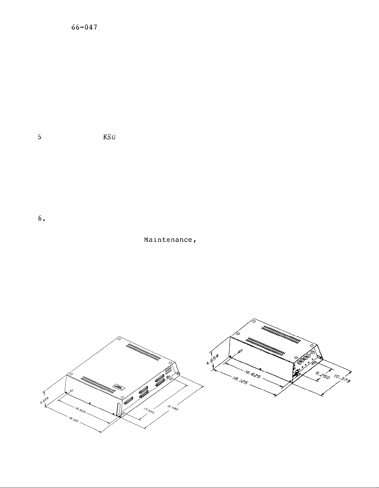
Full scale mounting templates are supplied in the packing boxes.
Installation
Hold or tape them to the mounting surface, and mark the location
of the mounting holes on the mounting surface as they are located
on the templates. The mounting dimensions and general equipment
locations are shown on Figure 2-l.
4.
Drill holes in the mounting surface of a proper size to
accommodate the hardware being used.
If necessary,
prepare these
holes with inserts, anchors or other attachment devices as
dictated by the type of mounting surface.
.
Attach the
and power supply cabinets to the mounting surface
with four (4) screws installed through the KSU mounting flange and
into the mounting surface holes.
elongated with an enlargement at one end.
Note that the flange holes are
This feature allows the
mounting screws to be partially installed in the mounting surface
before the cabinets are hung on them.
The flange holes on the
power supply cabinet have an enlargement at the center of the
elongated holes to allow the cabinet to be mounted with the power
connector and fuses facing either toward the right side or toward
the left side of the mounting location.
Place the individual telephone stations as desired and in keeping
with accepted industry and office standards.
can
Refer to Chapter 4, Naintenance,
be
wall mounted if necessary as they are desk/wall reversible.
for instructions in preparing a
A telephone station
desk/wall reversible station for wall mounting.
Figure 2-1. Mounting Dimensions'
Page 13
Installation
SYSTEM WIRING
System cabling may be routed concealed or visible as the installation
location requires.
Good engineering practices must be observed and
all applicable building codes must be adhered to. Tables 2-l through
2-5 and Figures 2-2 through 2-5 illustrate the system wiring and
connection points.
AC Power Connection
--
____
Connect the power interconnection cable between the power supply and
the KSU.
Do not connect or disconnect the power interconnection cable
while the AC power cord is connected to the AC outlet.
To apply AC power to the power supply,
the NEMA 5-15R outlet which supplies the dedicated 117VAC
electrical power.
A plug-in, power line surge protector should be
connect the AC power cord to
15
AMP
installed between the KSU power cord and the AC outlet.
Do not connect the AC power cord until the installation has
been checked per the SYSTEM CHECKOUT instructions given
later in this chapter.
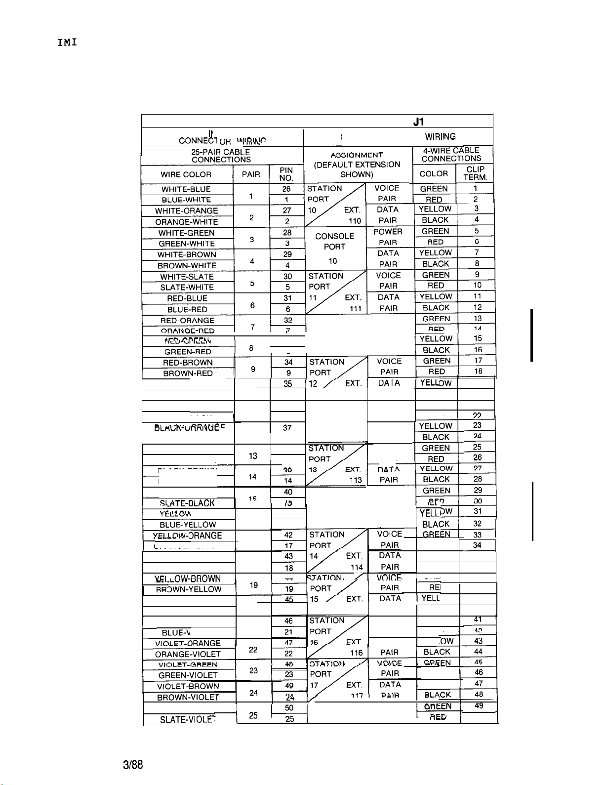
Line
Connections
The KSU interface connection for the TELCO or PBX lines is a 50-pin,
male connector.
A 25-pair cable,
properly terminated, must be
connected from the KSU connector to the demarcation point connector
(typically a 66M-xx connector).
To help insure that foreign voltages, which could appear on
the TELCO lines,
do not damage the system, verify that gas
discharge tubes or similar protection devices are installed,
and properly grounded,
in all connected TELCO lines.
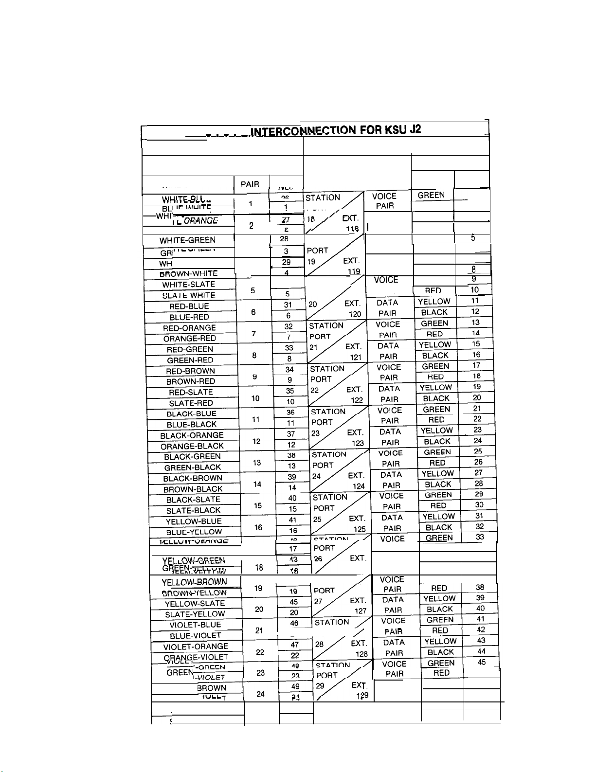
Station Connections
Connections between the KSU and the stations are typically
connector blocks which are cable connected to the KSU 50-pin
male connector.
station is 1500 feet using
The maximum distance allowed from the KSU to the
gauge, twisted-pair cable.
If spare conductors exist in the cables that are run between the
connector block and the station jacks,
it is a good practice to
connect them to earth ground. Doing this may help prevent them from
inducing radio frequency and/or AC interference into the system.
Page 14
IMI 66-047 Installation
The polarity between the individual wires in a particular
voice or data pair is not critical; however, do not connect
the voice circuits to the data circuits.
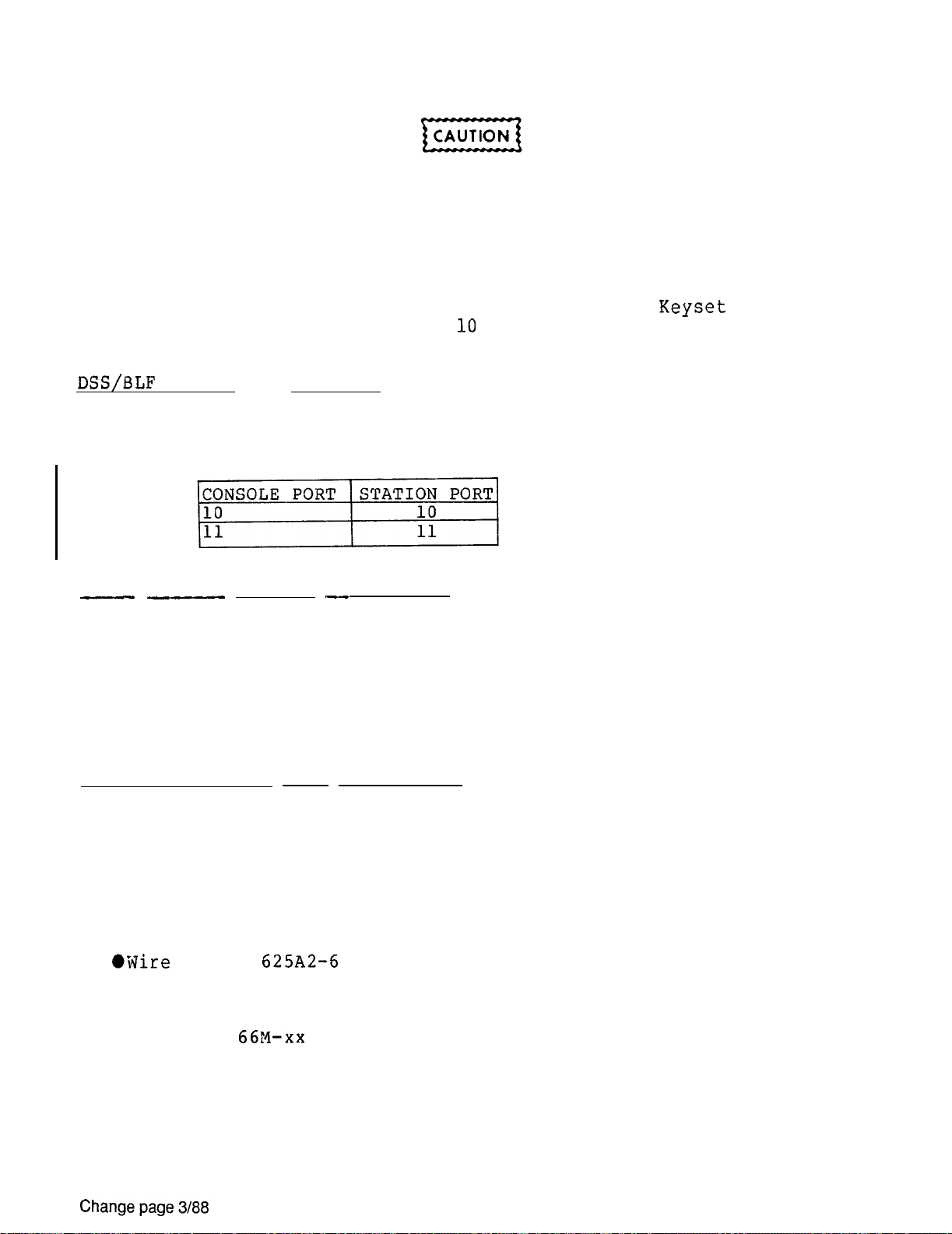
IMPORTANT NOTE
Station ports are programmed for the type of equipment that
is to be connected to them. A 22 Line/Feature Keyset must
be installed at station port
and/or station port 11 as
Class Of Service programming is performed from those ports.
--
The system provides two console ports. The console ports are
associated with companion station ports asfollows:
Power Failure Station Connections
The system provides four tip and ring pairs connected to lines 1, 2,
3, and 4 as emergency,
pairs are located as detailed on Table 2-4 and Figure 2-4.
failure pair is only active during a power failure.
standard,
single-line telephone, such as a type 2500, can be connected
power failure circuits. These power failure
A power
An industry
to a power failure pair and used to provide communications capability
should the AC power to the system be interrupted.
Station Auxiliary Jack Connections
For those stations equipped with an auxiliary jack, pins 3 and 4 (tip
and ring leads) of this jack are connected to pins 1 and 6 of the
station line jack. A 6-conductor station line cord is used, and the
third pair is designated as the auxiliary-pair.
Refer to Figure 2-5 for an illustration of a typical auxiliary-pair
wiring connection,
and note the following wiring considerations:
jack.
@Connect 3-pair cable between the station wall jack and an
auxiliary 66M-xx connector block.
l
Connect the voice-pair and data-pair from the auxiliary connector
block to the station connector block.
2-4
Page 15

IMI 66-047
*Connect the auxiliary-pair from the auxiliary connector block to
the desired termination.
@Connect an appropriate line cord between the auxiliary jack and
the auxiliary source equipment.
Installation
A-Lead Control Device Connections
The KSU can detect an A-lead (A and Al) control signal when it is
applied to lines 13
bridge-connected to these lines via terminal clips on the J-4 station
connector block.
details.
Data Device Connections
When a serial data printer is used for SMDR and COS printout, or a
video display terminal (VDT) is used to perform class of service
programming connect the data device to terminal clips on the J-4
auxiliary connector block.
and the KSU must not exceed 50 feet. Refer to Table 2-4 for
connection details.
When preparing a cable for connection to a data device, refer to the
manufacturer's manual for the equipment being interfaced, and make the
following wiring connections:
l
Wire the KSU RD line (data from device to KSU) to the device TD
(transmit data) output pin.
@Wire the KSU TD (data to device from KSU) pin to the device RD
(receive data) pin.
----
16.
Refer to Table 2-4 and Figure 2-4 for connection
An A-lead control device can be
The maximum distance between the device
(signal ground) pin to the device SG (signal
ground) pin.
the KSU CTS (clear-to-send status from device to KSU) pin to
the device RTS (request-to-send) output pin.
requires a positive voltage,
order to send data.
required,
the KSU to the device) pin to the device DSR (data-set-ready)
input pin.
required, wire the KSU PG (protective ground) line(s) to the
device protective ground pin(s).
wire the KSU RTS (request-to-send status signal from
with respect to signal ground, in
NOTE: The KSU
2-5
Page 16

IMI 66-047 Installation
The system defaults to 7-bit data with no parity at a baud rate of
1200.
match the data format and baud rate that is set by
Grounding
System
Configure the device,
per the manufacturer's instructions, to
programming.
It is required that a grounding wire, separate from the three wire AC
line cord, be used.
power supply for this purpose. Wire
A ground stud is located on the KSU and on the
or
insulated, solid
copper wires between these ground studs and a reliable earth ground
such as a metal cold water pipe or a building frame ground.
Common Audible and Auxiliary Station Interface
------
Two sets of relay closure dry-contact points are available at the J-l
and J-2 station connector blocks.
l
One set (J-l connections) provides a dry-contact closure whenever
any of the TELCO/PBX lines, connected to the KSU, ring.
l
The other set (J-2 connections) provides a dry-contact closure
whenever system station port 17 rings.
These contact closures track the ringing pattern in both cases.
The
contacts are closed during the ringing period and are open during the
silent period.
A typical connection is illustrated in Figure 2-2. Refer to the
paragraph headed Area Paging Interface for a discussion for using
these terminals i-is-alternate paging function.
Do not exceed a 1 amp at 24 volts
on these control terminals.
If the load requirements exceed
amp at 48 volts) load
this limit, connect the load through an external slave
relay.
DO NOT CONNECT THESE CONTROL TERMINALS
TO
THE 117VAC LINE.
Page 17

66-047
Installation
Area Paging Interface
----
-----
Station PA Port
Any unused station port can be programmed to be a PA port instead Of a
telephone station port (see Chapter 3 for programming details).
audio input of an external paging amplifier can be connected to
the audio pair of the station port as illustrated in Figure 2-3.
l
The audio input connection must be isolated with a 600 ohm to 600
ohm audio matching transformer. Terminate the audio input of the
PA system with a 620 ohm (nominal value) resistor.
l
If station port 39 is programmed as a PA port, the Common Audible
contact points are automatically reconfigured as PA enable
terminals.
dialed.
previously,
The contact closure now occurs when PA station 39 is
The normal common audible function, as discussed
is disabled as long as station 39 is a PA station.
If station port 41 is programmed as a PA port, the Auxiliary
Station Interface (station port 17 audible) contact points are
automatically reconfigured as PA enable terminals.
The contact
closure now occurs when PA station port 41 is dialed. The normal
auxiliary station interface function,
as discussed previously, is
disabled as long as station port 41 is a PA station.
Area Paging Interface 1 Line Port
A line port can be configured by class of service programming to be an
AUXILIARY port.
station
voice path to an external device. This is done from any
As an AUXILIARY port,
it can be used to couple a
allowed station by pressing the proper line key to select the
AUXILIARY port.
DTMF tones or dial pulses can be dialed through the
auxiliary port as needed.
If direct access area paging is to be part of the system, connect the
audio input of a paging amplifier to the line that is programmed to be
an AUXILIARY port. The input impedance of this port is approximately
ohms. A tone select,
desired.
If used,
the zone-select code must be dialed after the
zone-paging amplifier can be employed if
AUXILIARY port line select key is pressed.
2-7
Page 18

IMI 66-047
Installation
Key System/Multifunction
The system can be configured to operate as either a key system or as a
multifunction (hybrid) system.
Configuration is by way of a wire strap placed between clip terminals
27 and 28 of station connector block J-4.
The KSU is shipped from the factory as a key system (KF).
operation over to the multifunction
(MF)
system, add the strap.
To convert
The KF and MF designations are equipment type catagories as stipulated
in FCC rules and regulations, Part 68,
and appear as part of the FCC
Registration Number on the equipment label. The appropriate
registration number must be reported to the telephone company at the
time of connection along with other FCC mandated information. (Refer
to Installer/User Information Regarding FCC Rules and Regulations
------------
--
_____
-----
found in Chapter 1 of this manual.)
Operationally, the multifunction (hybrid) configuration enables a PBX
feature which may incur a higher monthly tariff to the telephone
company.
outgoing lines.
This feature allows dial access to (automatic selection of)
The specific Executech feature that is enabled by the
multifunction (hybrid) configuration is:
l
Line Group (Including Dial Access)
Music Interface
If music is to be part of the system,
connect a KX registered music
source to the KSU input jack (phono jack) provided for this purpose.
The impedance of this input is approximately 500 ohms.
adjustment of the music source may be necessary.
This may be done
Level
during system checkout.
Cassette
------
Recorder Interface
A customer provided, audio cassette, tape recorder can be connected to
the music interface jack.
stored and loaded via the recorder through this interface.
Class of service programming can be both
This
action is controlled from station 10 as detailed in Chapter 3, System
Programming.
2-8
Page 19
66-047
Installation
Table 2-1. Wiring For Station Connector Block J-l
SYSTEM INTERCONNECTION FOR KSU
KSU
JTERFACE
---
WI
CONNECTION BLOCK
4-WIRE CP
CONNECTIONS
COLOR
GREEN
RED
TERM.
CLIP
1
7
RED-SLATE
SLATE-RED
BLACK-BLUE
BLUE-BLACK
ORANGE-BLACK
BLACK-GREEN
GREEN-BLACK
BLACK-BROWN
BROWN-BLACK
BLACK-SLATE
/-BLUE
ORANGE-YELLOW
YELOW-GREEN
GREEN-YELLOW
I
YELLOW-SLATE
SLATE-YELLOW
VIOLET-BLUE1
‘IOLET
I
I
33
A
10 10
11
I
12 12
16
17
18
20 20 115
21
36
11
38
13
41
16
AA
RESERVED
CONSOLE
PORT
11
RESERVED
112 PAIR
POWER
PAIR
DATA
PAIR
VOICE
PAIR
PAIR
VOICE
PAIR
DATA
BLACK
GREEN
REP
GREE
REP
RED
YELLOW 35
BLACK
GREEN
3 38
.ow
BLACK
GREEN
REP
YELL
20
21
19
36
37
39
40
Change page
VIOLET-SLATE
RED
YELLOW 1
,
I
,
1
, , , , , . . . .
COMMON AUDIBLE
50
2-9
Page 20
IMI 66-047
Installation
Table 2-2.
KSU INTERFACE
CONNECTOR WIRING
25-PAIR CABLE
CONNECTIONS
WIRE COLOR
I
ORANGE-WHITE
EEN-WHITE
ITE-BROWN
Wiring For Station Connector Block J-2
SYSTEM
IF
I
I
PIN
MA
26
I
3 PAIR
4
30
(DEFAULT EXTENSION
PORT
I STATION
STATION
PORT
CONNECTION BLOCK WIRING
ASSIGNMENT
SHOWN)
1 PAIR
DATA YELLOW
POWER
DATA
PAIR
PAIR
4-WIRE CABLE
CONNECTIONS
COLOR
GREEN
RED 1
RED
YELLOW
BLACK
GREEN
n
CLIP
TERM.
1
2
3
4
6
7
ORANGE-YELLOW
VIOLET-I
BROWN-v
VIOLET-SLATE
;LATE-VIOLET
,
17
,
I
44
I
STATION
[PORT
I
50
25
25
AUXILIARY INTERFACE
126 PAIR
STATION 17
PAIR
DATA
DATA
PAIR
RED
YELLOW
BLACK
GREEN
YELLOW 47
BLACK
GREEN
RED
34
35
36
37
46
48
49
50
Page 21
'IMI 66-047
Installation
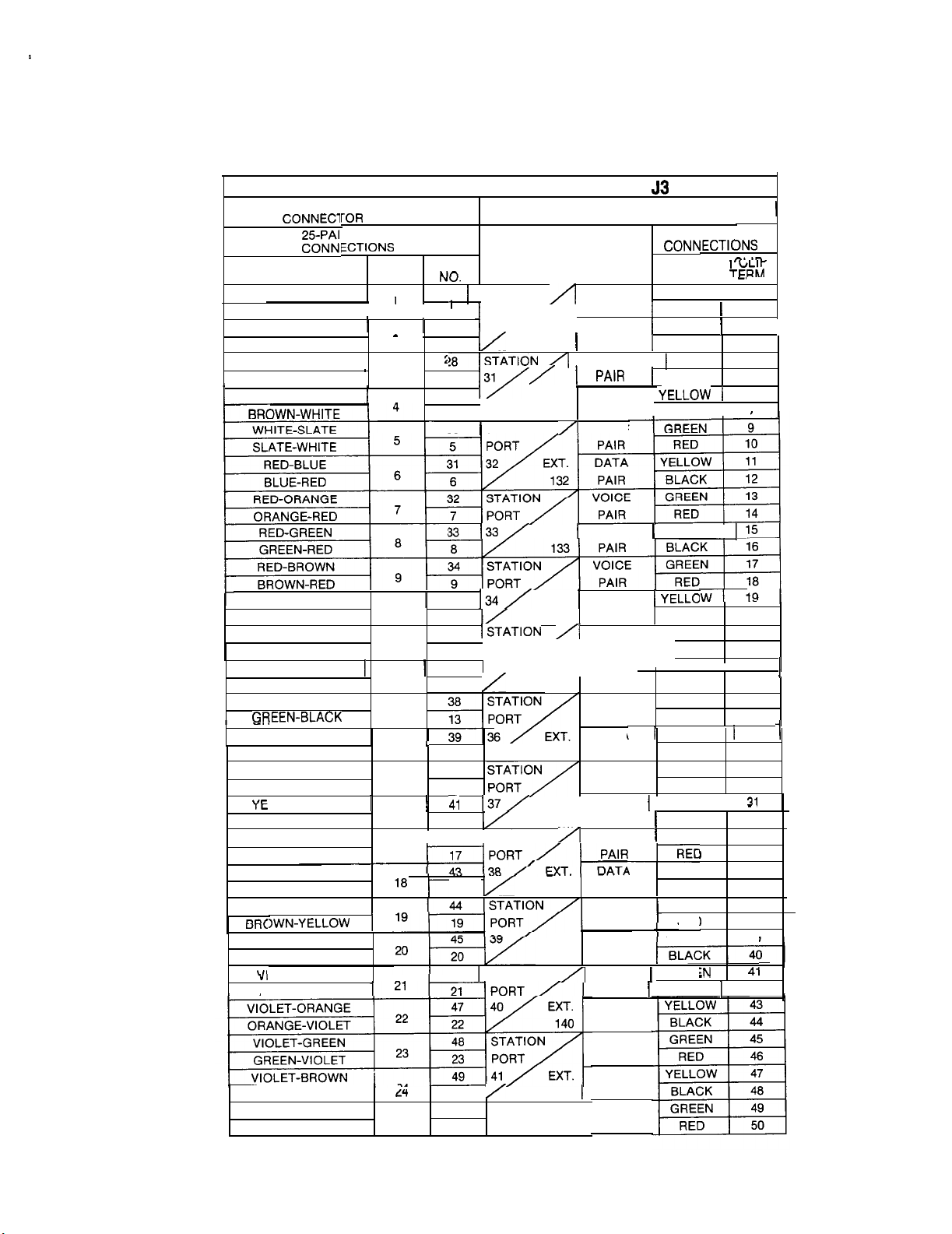
Table 2-3.
Wiring For Station Connector Block J-3
SYSTEM INTERCONNECTION FOR KSU
KSU IN
TERFACE
WIRING
R CABLE
WIRE COLOR
WHITE-BLUE 1 26 1 STATION
BLUE-WHITE
WHITE-ORANGE 1 1
ORANGE-WHITE
WHITE-GREEN
GREEN-WHITE
PAIR
I
2 2
3 3
PIN
,
,
I
27
.
29
A
30 1 STATION
CONNECTION BLOCK WIRING
ASSIGNMENT
(DEFAULT EXTENSION
SHOWN)
VOICE
PORT PAIR
30 /I EXT. DATA 1YELLOW 1
130
PAIR
VOICE
31
EXT.
EXT. 1 DATA
DATA
131 PAIR
VOICE
4-WIRE CAE
COLOR 1
I
GREEN 1 1
RED
GREEN
1
RED 6
BLACK 1
3LE
I
,
. . . . .
2
3
4
5
7
8
PORT
EXT. 1 DATA
134
PAIR
VOICE 1 GREEN
PAIR
EXT.
EXT. ) DATA 1 YELLOW 1
EXT.
DATA
135 PAIR
VOICE
DATP
VOICE
137 1
139 PAIR
SPARE
PAIR
VOICE 1 GREEN
VOICE
PAIR REC
DATA YELLOW 39
VOICE 1 GREE
PAIR 1 RED
DATA
PAIR
VOICE
PAIR
DATA
141 1
PAIR
RED-SLATE
SLATE-RED
BLACK-BLUE 1
BLUE-BLACK
BLACK-ORANGE 1 __ 1 37 35
ORANGE-BLACK
BLACK-GREEN
BLACK-BROWN
BROWN-BLACK
BLACK-SLATE
SLATE-BLACK
LLOW-BLUE
BLUE-YELLOW
YELLOW-ORANGE 1
ORANGE-YELLOW
YELLOW-GREEN
GREEN-YELLOW
YELLOW-BROWN GREEN
YELLOW-SLATE
SLATE-YELLOW
OLET-BLUE
BLUE-VIOLET
BROWN-VIOLET
VIOLET-SLATE
SLATE-VIOLET
10
11
.
12
13 PAIR
14 14 136 PAIR
15 15 PAIR RED 30
16 16
17
1
25 25
10
36
11
l/l----F
12
40
42
/STATION
18 138 PAIR
46 1 STATION
24
50
RED 22
YELLOW 1 23 1
BLACK
GREEN
RED
BLACK
GREEN 29
YELLOW
BLACK
20
21
24
25
26
27
28
32
33
34
35
36
37
38
42
2-11
Page 22

IMI 66-047
Installation
Table 2-4.
Wiring For Auxiliary Connector Block J-4
SYSTEM INTERCONNECTION FOR KSU
NTERFACE
KSU
WIRE COLOR 1
WHITE-BLUE 1
ORANGE-WHITE
WHITE-GREEN
WHITE-BROWN
BROWN-WHITE
WHITE-SLATE
ATE-WHITE
RED-BLUE
BLUE-RED
RED-ORANGE
ORANGE-RED
RED-BROWN
s-.
BLACK-BLUE
RI I IF-RI
----
BLACK-ORANGE 1 I 37
. .
WIRING
CABLE
I
I
I
PAIR
1
2 2
4 4 STA. 4
PIN
NO.
26
27
.
5
6 6
7 7
11
30
31
32
(DEFAULT EXTENSION
POWER FAIL
1
5
33
34
9
35 TO A
36
STA. 1
POWER FAIL RING 1
STA. 2 TIP 4
STA.3 1 RING 1 1
AUX. EQUIP.
INTERFACE RING
CO LINE 13 Al BLACK
AUX. EQUIP.
INTERFACE RING
COLlNE14
AUX. EQUIP.
INTERFACE RING 1
AUX. EQUIP.
INTERFACE
CONNECTION BLOCK WIRING
,
4-WIRE
COLOR
I
I
GREEN
YELLOW
ASSIGNMENT
SHOWN)
TIP
RING
TIP
RING 1 1
TIP c
TO
TO A
TO
A YELLOW
TIP
TIP
TIP
.
TERM.
I
I
RED 14
RED
RED 22
‘ELLOW
1
2
3
6
7
9
12
13
15
18
19
20
21
23
I
.
SLATE-VIOLET
RESERVED
SPARE
I
I
1
2-12
Page 23
IMI 66-047
Installation
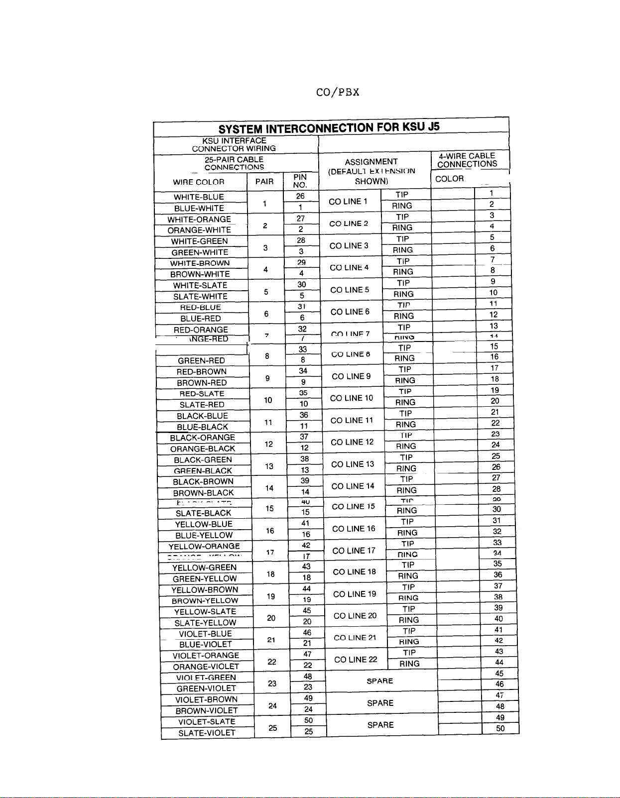
Table 2-5. Wiring For CO/PSX Connector Block J-5
CONNECTION BLOCK WIRING
CLIP
TERM.
I
ORP
RED-GREEN
BLACK-SLATE
ORANGE-YELLOW
2-13
Page 24
IMI 66-047
Installation
CONNECT TO CLIP TERMINALS ON
CONNECTOR BLOCK PER CHART
I
KSU
INTERNAL
SWITCHING
I
-----
COMMON AUDIBLE J-l CLIPS
STATION 17 RINGING J-2 CLIPS
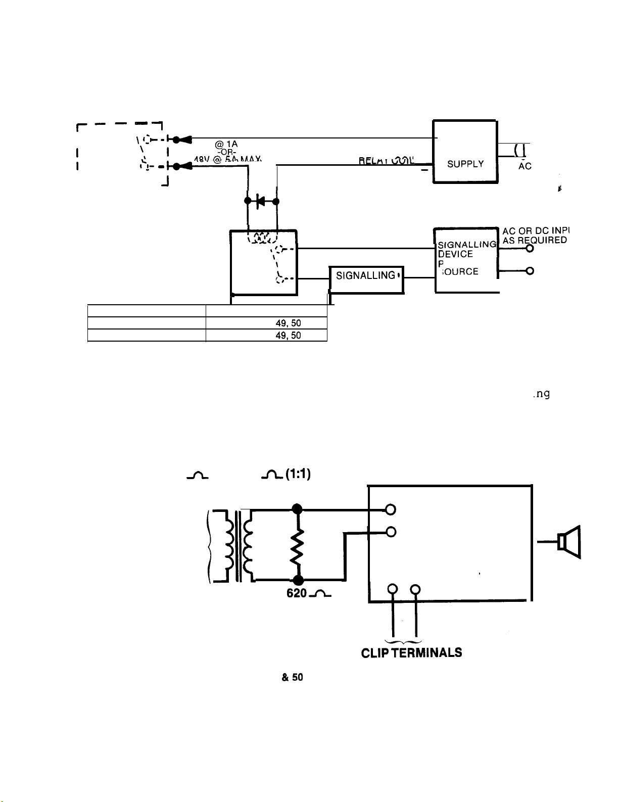
Figure 2-2.
FUNCTION CONNECTIONS
24V
Common Audible/Auxiliary Station Interface Wir
MAX
VOLTAGE CLAMPING DIODE
RECOMMENDED
SLAVE
RELAY
OUTPUT AS
REQUIRED BY
DEVICE
(Typical Connection)
A”
+
LOW
VOLTAGE
POWER
‘OWER
S
A
JT
I
600
TO KSU STATION
PORT 39 OR 41 IF
ENABLE IS REQUIRED
OR TO ANY UNUSED
STATION PORT IF
ENABLE IS
NOT REQUIRED.
FOR PA ENABLING, CONNECTTO
CONNECTOR BLOCK
. BLOCK J-l CLIPS 49
l BLOCK J-2 CLIPS 49 & 50 FOR STATION PORT 41 PA ENABLE
TO 600
AUDIO
TRANSFORMER
Figure 2-3.
PA SYSTEM
AUDIO INPUT
ENABLE INPUT
FOR STATION PORT 39 PA ENABLE
PA Connections
ON
2-l 4
Page 25

: IMI 66-047
Installation
L
Figure 2-4a.
System Interconnection
Typical Connections
Page 26

Installation
Figure
System Interconnection
Typical Connections
Page 27

IMI 66-047
Installation
2-16
Page 28

Page 29

IMI 66-047 Installation
SYSTEM CHECKOUT
Initial Condition_
The system operating features are set to a set of default conditions
at initial power up. These conditions provide a basic operating
system with a known set of parameters,
and the system should be
initially checked out with the default conditions in place. At
anytime while the system is operating,
default conditions can be reset
from station port 10 or 11 per the instructions provided in Chapter 3.
Check Out
Check the KSU and telephone installation for proper operation by
performing the following resistance and voltage measurements.
Resistance Check
Make the following resistance measurements at the station connector
blocks under the following conditions.
l
KSU AC power cord disconnected from electrical outlet.
l
Power interconnection cable connected between KSU and power
l
KSU connected to station connector blocks.
l
Stations wired,
l
Bridging clips removed from blocks to isolate stations from KSU.
1.
Measure the resistance of each installed station and wiring from
the station side of the connector blocks.
and wiring punched down on blocks.
Resistance values will
vary with cable length and station type but should be within the
following limits.
MEASURED PAIR
MEASURED STATION RESISTANCE IN OHMS
22 LINE/ 3 AND 8 SINGLE DSS/BLF
VOICE PAIR
DATA PAIR
FEATURE
40
0.3
150 40
100 40
LINE LINE
150 40
150
150 0.3
0.3
100 0.3
CONSOLE
100
100 .
OPEN OPEN
2.
Measure the resistance of the KSU and cables from the KSU side of
the station connector blocks. Resistance values should be within
the following limits.
MEASURED PAIR MEASURED KSU RESISTANCE IN OHMS
VOICE PAIR 40
DATA PAIR
0.3 -
50
0.5
2-17
Page 30

IMI 66-047
Installation
Voltage Check
the following voltage measurements at the station connector
blocks under the following conditions
l
Bridging clips installed
power connected to the
Measure the voltage across one voice line and one data line and then
across the other voice line and the other data line for each even and
odd station. The measured voltage must be as follows:
UNIT UNDER
TEST
TYPICAL EVEN
STATION
Repeat for
each even sta.
TYPICAL ODD
STATION
Repeat for
each odd sta.
BLOCK METER LEAD
CONNECTION POLARITY
I I
, Voice 1
Data
3
Voice 2
4
----
Data
Voice
Data
11
10
12
i-i
MEASURED
VOLTAGE
-33
-33
5
5
5
I
I
VDC
VDC
Variant readings can indicate a possible wiring, station, or KSU
problem.
General Check
1.
Check the red light emitting diode (LED) system status indicator.
Be sure that it is on steady.
If it is off or flashing,
disconnect and reconnect the AC power plug. If the indicator is
still not on steady,
refer to the Failure Analysis Flow Chart
found in Chapter 4.
2.
Refer to the station User's Guide for operating information.
Perform a general operational test of the system by exercising the
system features from station port 10 or 11. Operational
parameters are per the system default conditions as detailed in
Chapter 3 until Class Of Service (COS) programming is performed.
3.
Once the basic system is verified as operational, perform the COS
programming.
Change page
2-18
Page 31

CHAPTER 3
SYSTEM PROGRAMMING
Programming
GENERAL INFORMATION
Class Of Service (COS) programming consists of the following major
categories: General System COS, Toll Table Entry, Line COS, and
Station COS.
l
All COS programming commands must originate at a 22 Line/Feature
Console installed at console port
or lla respectively.
No
COS
programming commands -will be accepted from any other stations
connected to the system.
l
Programming overlays are included with each system for use in
identifing the keys required for COS programming.
over the keys of the station installed at station port
designates the A-field and B-field keys.
over the keys of
the
console installed at console port
The other overlay fits
One overlay fits
or 11 and
or lla
and designates the C-field keys.
l
System and line COS programming do not require that a se
uential
process be followed once the base level program entry mo e has been
established except where noted herein.
Station COS programming does
follow a sequential process.
l
Prior to taking any programming action, determine the system, line
and station
conditions and all toll restriction requirements.
Record this data on the programming reference tables included within
the programming procedures.
l
A set of COS values can be recorded on cassette tape from a
programmed
another system.
system
and later re-loaded into the same system or into
This method of programming can be employed in lieu
of using the step-by-step programming sequence.
l
A complete or a partial printed record of the COS program values can
be obtained with a serial data printer connected to the SMDR output
lines of the KSU.
Complete details concerning this procedure are
included at the end of this chapter.
3-l
Page 32

SPECIAL PROGRAMMING
FOR SINGLE-LINE KEYSETS
Several programming steps under COS programming must be observed
proper operation of a Single-Line Keyset.
@When the system is strapped for key system configuration, the
Single-Line Keyset is an intercom only station. It can be
configured for private line only by programming the applicable
station port for the prime line automatic feature. When the port is
programmed with the prime line automatic feature, the Single-Line
the system is strapped for the multifunction (hybrid) system
configuration,
to originate outside calls with a Single-Line Keyset,
one or more lines must be programmed into a line group.
order to receive outside calls on a Single-Line Keyset, the call
be answered by an attendant using a multiline station and
transferred to the single-line station. Otherwise,
the Single-Line
preference feature with ringing enabled on all desired lines.
Alternately it can be programmed to have the prime line automatic
feature with ringing enabled at the prime line.
BASE LEVEL PROGRAM ENTRY MODE
The first step in any COS programming sequence is to enter the base
level programming mode from station port
10
or 11.
Once in this mode,
COS can be set as desired.
To
enter base level:
1.
Press the
Press the following keys in sequence: * 7 4 6
2.
ITCM
key.
The dial tone will sound.
that the dial tone stops and a tone burst sounds to indicate
that the base level programming mode is entered.
3.
Press the *
key.
The dial tone will return as a confirmation
that the base level mode is active.
4.
Proceed from this point to program the system, line, or station
COS and the toll restriction tables.
Page 33

'IMI 66-047
Programming
CLASS OF SERVICE DEFAULT
The system can be defaulted to a standard class of service per the
following procedure. The default conditions are listed at the
beginning of each COS programming procedure and shaded on the
programming reference charts.
1
Press
ITCM * 7 4 6 *
2 Press program key C38
3
Press keypad key(s) to choose default settings
1
= system COS default
2
line COS default
4
= pulse dialing
5 = tone dialing
all lines
all lines
station
= One
default
column SMDR line
6
flexible key/function default
= Two 40 column SMDK lines
RECALL = Tape baud rate of 100
SAVE
= Tape baud rate of
7051684 = master default (CAUTION: resets all values
and clears all stored
Do not perform
while system is in use)
4 Press *
MONITOR
OVERLAYS
Several different telephone and console overlays are packed with the
system.
The overlay to be used is dependent upon the particular
models of equipment connected to the programming station port (10 or
11) and the respective console port
overlays are illustrated in Figure 3-l.
or
Full-scale copies of the
overlays are also included at the end of this chapter.
The programming
The full-scale
copies can be removed and prepared for use if needed.
Page 34

OVERLAY:
OVERLAY: 703500566
703500467
. . .
J
Figure 3-l.
Programming Overlay Identification
Page 35

Programming
------------------------
SYSTEM COS PROGRAMMING PROCEDURE
SYSTEM DEFAULTS
Intercom signalling
Pause time
1 second
Timed Hold recall time
= 60 seconds
Printer baud rate = 1200 baud, 7-bit data
Central message Desk = not assigned
l
Unanswered call transfer
= 20 seconds
Print length = 40 Col.
Port Assignments: All station ports= 22 Line/Feature Keyset
All console ports = 40-Key DSS/BLF Consoles
l
Tape baud rate = 100
-----------------------------------------------------------------
PROCEDURE
1
Press
Set recall/flash time
Press program key
Press keypad key for time
ITCM * 7 4 6 *
(base level entry if not active)
Set pause time.
3
l
Press program key C35
l
Press keypad key for time
Press * l Press *
5a
Set timed hold recall time
4
Press program key C36
l
Press keypad key for time
l Press *
Set the baud rate of printout
l
Press program key C39
Set baud rate with keypad
l
Press
voice first
5b
Set line length of printout
6
Choose intercom first signalling
l
Press RECALL for voice
l
press SAVE for tone
l
Press *
l
l
Press 8 for two 40 col.
Press *
Specify central message desk
(one per system allowed)
Press #
l
Press keypad keys 010
to choose port 10
l
Press *
9
Specify station type for each station port
l
Press keypad keys 010
l
Press console key to specify station type
041
41
073 to identify station port 010
Set recall time for
unanswered call transfer
l
Press keypad keys for time
Press *
Cl8 = 32-Key Console without call announce
32-Key Console with call announce
=
= LCD Telephone
c22
= Single-Line Keyset (hotel telephone)
C25 = Single-Line Keyset (administrative telephone)
C23 = 3 and 8 Line
Dial 3-digit code (100
l
Press
and repeat steps for each active station port
C24 =
399) to assign extension number (optional)
22 Line/Feature Keyset
Press program key C38
Press program key C33
073
NOTE: The step 9 action sets STATION COS for
port to the DEFAULT
conditions for that type of station.
Change
3-5
-continued
Page 36

66-047
Programming
System
10
Specify console type for each console port
l
l
Press
l
Select baud rate of tape data
Press program key C38
l
l
l
programming procedure-continued
Press console program key
to enable port selection
Press console program key to specify console port
= console port
= console port
console program key to specify console type
=
70-Key console
=
Repeat port and console selection steps for all
12 Press *
Press
RECALL for 100
Press SAVE for
baud
Press
proceed to next COS
to exit or
Press *
3-6
Page 37

66-047
Programming
SYSTEM
PROGRAMMING REFERENCE TABLE
@Shading denotes system default conditions
off values chosen for system being programmed
RECALL/FLASH TIME
5A
HOLD RECALL TIME
KEY 1 TIME 1 ENTRY
Note: 0 program selection (disabled) enables exclusive hold condition (when set at station) to place
line on hold that cannot be released
at any other station.
INTERCOM FIRST CHOICE
CENTRAL MESSAGE DESK
STATION PORT ASSIGNED
3-7
Page 38

Programming
.
. .
013 rt3
014 vi4
015
016
017
016
019
DIALING
EXTENSION
,
I
SPECIFY CONSOLE TYPE FOR EACH CONSOLE PORT
CHOOSE PORT
PORT
PORT lla
CHOOSE CONSOLE TYPE
70-KEY CONSOLE
40-KEY CONSOLE
32-KEY CONSOLE
11
KEY
BAUD RATE OF TAPE DATA
ENTRY
Change page
3-8
Page 39

Programming
TOLL
In order for toll restriction to take effect, the following three-fold process must occur.
One or more toll tables must be entered.
l Toll tables must be assigned to all appropriate lines.
l Toll tables must be assigned to all appropriate stations.
Only the toll table(s) which are entered and assigned to both a line and a station using that line
will invoke any toll restriction.
TABLE ENTRY PROCEDURE
1.
Determine the types of dialing restrictions which must be imposed on the system. Typically,
this includes access codes which result in toll charges, and certain local numbers as
desired.
2. If the restricted dialing codes will be imposed consistently on most or all stations in the
system, list them on one or two tables. If wide variation in the dialing restrictions is planned,
spread the listing out across several tables.
3.
Strategically group the listings on the tables so that a list of restrictions can be applied to a
particular station or group of stations.
4. Designate each table as a DENY table or as an ALLOW table. The numbers entered in a
DENY table are prevented from being dialed. ALLOW tables take precedence over DENY
tables. Therefore, an entry in an ALLOW table will provide an explicit exception to an entry in
a DENY table. Note that the system a/ways permits the dialing of any number not explicitly
denied. Also, system speed dial numbers will not be toll restricted unless specified by station
COS programming.
l Example A: Provide a simple and broad toll restriction format by creating a DENY table
with two entries: Entry (1) = 1 Entry (2) = 0. This format prevents all long distance and
operator calls.
l Example B: Prevent the dialing of all numbers within the (804) area code, while allowing
the dialing of one specific number within that area code, by entering 1804 in a DENY table
and 18049782200 in an ALLOW table. Alternately, allow all numbers in the 978 exchange
by entering 1804978 in an ALLOW table.
5.
Press the # key in place of a particular digit to condense a range of numbers into one entry.
character is a “match-anything” digit, and can be included in an entry in either a DENY
table or an ALLOW table.
l Example A: If
and 397 dialing is to be prohibited, list one entry of
on a
DENY table to cover them all.
l Example B: Since area codes typically have a 1 or a 0 as a middle digit, prevent long
distance calls to those area codes by entering 1
and 1#0# in a DENY table.
6.
Since it is important that emergency numbers never be restricted, always create an ALLOW
table with entries of 911 and 1911 to override any DENY tables that have been created.
7.
If the system is installed behind a PBX, include an access code as part of every table entry.
8.
Once these tables are completely filled out, enter the restriction planning tables on the line,
and station programming reference charts to record the planned toll restrictions for the
system.
3-9
Page 40

66-047
Programming
1
Press
2
Press program
3
Press console key
TABLE
4
Select table type
l AllON
6
Dial number
(Press
* 7 4 6 *
key
C37 (enter toll program mode)
Cl0
Ci2 Cl3 Cl4 Cl5
C21
10 11 12 13 14
press program key
press program key
digits max.)
for "match anything"
digit)
6
Repeat steps 3 through 7 until
all tables are programmed
PROGRAMMING PROCEDURE
(base level entry if not active)
C25 to select table number (1
C23 C24 C25
15
5 Select table entry
l
Press program key Al
7
steps 5 and 6
until all numbers are
programmed in table.
9 Press *
16)
A4
Press
RESTRICTION TABLE 1
TYPE: ALLOW DENY
NTRY
3 6
ENTRY NUMBER (16 MAXIMUM)
RESTRICTION TABLE 3
DENY
to exit or proceed to next
I
I I I
PROGRAMMING KEFERENCE TABLES
TYPE: ALLOW
13 14
15
16
I I
TABLE ASSIGNMENT: LINES
I
NTRY
,
RESTRICTION TABLE 2
DENY
RESTRICTION TABLE 4
ENTRY NUMBER (16 MAXIMUM)
3
programming step.
STATIONS
DENY
1
I
I
TYPE: ALLOW
TABLE ASSIGNMENT. LINES
RESTRICTION TABLE 5
DENY
STATIONS
I
I
I
TYPE. ALLOW
ENTRY
,
RESTRICTION TABLE 6
DENY
ENTRY NUMBER (16 MAXIMUM)
(6
(12
16
I
Page 41

66-047
Programming
RESTRICTION TP
TYPE: ALLOW DENY
ENTRY
3
TYPE. ALLOW DENY
NTRY
15
TYPE: ALLOW
ENTRY NUMBER (16 MAXIMUM)
4 5
6
RESTRICTION TABLE 9
ENTRY
RESTRICTION TABLE 11 RESTRICTION TABLE 12
DENY
RESTRICTION TABLE 6
TYPE: ALLOW DENY
7
9
13 14
15
t i
16
I
TABLE ASSIGNMENT: LINES
I
TYPE: ALLOW DENY
I
NTRY
TABLE ASSIGNMENT: LINES
TYPE: ALLOW DENY
I
(2 (4
ENTRY NUMBER (16 MAXIMUM)
STATIONS
RESTRICTION TABLE 10
ENTRY NUMBER (16 MAXIMUM)
(6 (7
(10
STATIONS
(14 (15
TABLE ASSIGNMENT: LINES __
RESTRICTION TABLE 13
TYPE: ALLOW DENY
TABLE ASSIGNMENT. LINES __
TYPE: ALLOW
III
DENY
I I
STATIONS
STATIONS
STATIONS
TABLE ASSIGNMENT: LINES
I
TYPE: ALLOW DENY
1
TYPE: ALLOW
ENTRY
3
STATIONS
RESTRICTION TABLE 14
ENTRY NUMBER (16 MAXIMUM)
RESTRICTION TABLE 16RESTRICTION TABLE 15
DENY
ENTRY NUMBER (16 MAXIMUM)
4
(9
I
I
3-11
Page 42

IMI 66-047
LINE DEFAULTS
Programming
LINE COS PROGRAMMING
l
Line type = TELCO
Dial Mode
Toll Tables = none
DTMF
l
assigned
PROCEDURE
1 Press
ITCM
* 7 4 6 * (base level entry if not now active)
Perform all applicable steps.
Press program key per chart
below to choose line 1
4
Select line group
Press program key:
(multifunction
l
None = key C41
l
Gp 1 = key C34
l
Gp 2 = key C35
only)
Gp 3 = key
l
Gp 4 = key C37
6 Select privacy mode
Press program key:
l
Private = key C28
l
Non-private = key
Line groups
none assigned
Privacy status = private
Abandoned Hold Timeout msec.
3 Select line type
Press program key:
l
Disabled = key C38
l
22
Auxiliary = key
l
CO/PBX = key
Select dialing mode
Press program key:
l
Pulse/tone = key C26
Tone only = key
Assign toll tables
Press program key(s)
l
Clear all = key C3
l
Assign = keys Cl0
TABLE KEY [TABLE
1
11
3
C25
Set abandoned hold timeout period
Press program key
l
300 msec.
l
msec. = key 31
key
10 Press *
Press MONITOR
to exit or proceed to next COS programming step.
3-12
Repeat steps 2
for each line
8
Page 43

66-047
l Shading denotes line default conditions.
. Check off
3
enter the values chosen for the lines being programmed.
EATURE
INE
4
5
6
Programming
LINE COS PROGRAMMING REFERENCE TABLE
RESTRICTION
7
TABLE
ASSIGNMENT
ABANDONED
HOLD TIMEOUT
AND STATION
ASSIGNMENTS
NUMBERS
Power Fail Lines (1, 2. 3, and 4)
A-Lead Control Lines (13. 14.
and 16)
3-13
Page 44

66-047
STATION COS PROGRAMMING
STATION DEFAULTS
l
PA port
l
Ringing line preference
disabled
Executive override = disabled
Prime line/group = none
Single Line Keyset accesses intercom
Personal ringing tone
Toll tables = none assigned
= tone
Line access denied = none
l
Idle line preference = none
All-call receive
l
All-call originate = enabled
enabled stations 10, 17, 39 and 41
Zone page receive = disabled
Ringing assignment = all lines ring
on stations 10, 17, 39, and 41
Origination denied
l
Night transfer = all lines ring on
none
Reserved intercom link
Message originate = disabled
Zone page originate = disabled l Line/key assignment:
l
Automatic hold = disabled
l System speed dial toll
3 and
Line Keyset
keys
= disabled 22 Line/Feature Ke set
Voice announce block
Privacy status = private
-----------------------------------------------------------------
disable-
l
B-Field
keys
keys
= lines 1 = 8
PROCEDURE
Programming
none
lines
22
Perform all steps in sequence.
l
Skip those steps not required.
Press
* 7 4 6 *
(base level entry) (program entry)
Specify station to be programmed 4
and perform applicable steps
l Press keypad keys 010-041
to select station port 010
041
Action defaults following settings:
l
PA port
l
Prime line
l
Voice blocking
l Executive override
Enable PA port
(DO NOT PROCEED BEYOND
THIS STEP
Press program key
l
Return to step 2
5
intercom calls
Press
Message wait-originate
l
Automatic hold
l
System
l
Ringing line preference
speed dial toll rest. 7
Enable toll table restriction
on system speed dial numbers
Press program key Cl3
Enable executive override
l Press program key Cl2
key C41
IF PERFORMED)
continued
3-14
Page 45

IMI 66-047
Programming
Station COS
continued
8 Choose personal ringing tones 9
(22 Line/Feature Keysets)
TONE 1 =
. TONE 2 =
l
TONE 3 = program key Cl6
. TONE 4 =
program key Cl4
program key Cl5
program key Cl7
10 Enable message wait originate
Press program key C27
16
Set automatic hold
Press program key C26
Select prime line
or prime group
Press program key per chart
to select line 1
22
or press ITCM to select
intercom line
Press program key per
chart
to choose prime group
12
Set ring
Press
l
Press console key
ing
program key
preference
13
(clears previous settings)
l
Press program key(s) per
chart in step 11.
15 Select automatic privacy release 16
Press console key
(clears previous settings)
Press program key(s) per
chart in step 11.
l
Press console key C23
(clears previous settings)
l
Press program key(s) per
chart in step 11.
Select ringing assignments
RINGING
Press console key Cl8
(clears previous settings)
l
Press program key(s) per
chart in step 11
DELAYED RINGING
l
Press console key Cl9
(clears previous settings)
l
Press program key(s) per
chart in step 11.
Select access denied
l
Press console key C22
(clears previous settings)
l
Press program key(s) per
chart in step 11.
Select idle line preference
l
Press console key C24
(clears previous settings)
Press program key(s) per
chart in step 11.
3-15
-continued
Page 46

IMI 66-047
Programming
Station COS
continued
To clear all toll tables assigned
Press program key C25
Reserve intercom link
Press #
l
Press keypad key l-7
to reserve link l-7
Press 0 key for no reserved link
Press console key Cl8 to
continue with next step
l
Press RECALL to disable all paging assignments (if desired)
and/or zone paging
Specify toll tables
Press program key
ALL-CALL
Press program key A4 to originate
l
Press program key A8 to receive
Press console key Cl8 to continue with next program step
ZONES A, B, AND C
l Press #
l
Press program keys Al-A3 and AS-A7 to enable zones
ORIGINATE
KEY
C
l
Press console key Cl0 to continue with next program step
RECEIVE
C
continued
3-16
Page 47

IMI 66-047
Programming
Station COS
(non-square configuration), if required.
3 AND
l
l
LINE KEYSET
Press program key C39
Press program key C34
Fast tone bursts will
Press program key per step 11 chart to assign lines 1
* Press RECALL key to disable line appearance
Tone bursts stop
Repeat for each line assigned
22 LINE/FEATURE KEYSET
l
Press program key C39
Assign Lines To
l
Press key
l
Press program key per step 11 chart to-assign lines 1
Tone bursts stop
l
Repeat for all keys requiring line appearance
continued
-or-
C41 to choose line keys 1
sound
Keys
assiqned (A or B field)
22
Fast tone bursts sound
22
Disable Line Appearance At Keys (clears any prior assignment)
l
Press key to be denied appearance
l
Press
tone bursts stop
Fast tone bursts sound
Repeat procedure for all required key locations
Assign DSS To Keys
l
Press key
l
Press keypad keys 010
be assigned (A or B field)
Fast tone bursts sound
041 to choose station ports 10
41
Tone bursts stop
l
Repeat for all keys requiring DSS assignment
Assign Autodial To Keys (clears any prior assignment)
l
Press key to
Press RECALL key
l
Repeat procedure as required for all autodial keys
(A or B field)
tone bursts
Fast tone bursts sound
Assign Dynamic Loop Keys (Clears any prior assignment)
l
Press key
Press RECALL key
l
Repeat for B2 and B3 if required
or
Fast tone bursts sound
tone bursts stop
continued
3-17
Page 48

IMI 66-047
Programming .
Station COS
continued
23 Press *
24b
Press program
Press keypad keys 010
Block
program a group of stations with same COS as previously
key
c41
041
programmed station
l
Press BOLD
Press keypad keys to specify model station
Press keypad keys to specify first station in block
l Press keypad keys to specify last station in block.
Note:
Flexible key/function assignments for station port
cannot
be
changed 'by
block
programming.
24b
is not performed, repeat steps
5 through 24a for each station in system.
26 Press * MONITOR to exit programming.
10
or 11
end
3-18
Page 49

'IMI 66-047
Programming
STATION
(Copy This Page To Provide Additional
l
. Check
the fines being programmed.
STATION PROGRAMMING MODE
or enter the values chosen for
COS PROGRAMMING REFERENCE TABLE
Reference
Sheets)
15-18
Page 50

COS PRINTOUT
Programming
COS AND SMDR PRINTOUT
from station port
obtained.
When the printer is being used to obtain a COS printout,
or 11,
to print the class of service
the Station Message Detail Recording (SMDK) function is temporarily
SMDR data collection is continued by the system during a COS
printout operation; however, if more than two calls are logged for any
one line, call records may be lost.
1 Press ITCM * 7 4 6
* (base level entry if not active)
2 Press program key
3 Choose desired printout
Press program key per chart
All COS
System COS
Line
Toll Tables
All station COS
One Station COS
c41
c34 plus 010
041
to choose station port
4
COS printout begins immediately
To abort printout,
Press *
press program key
(ends procedure)
SMDR
The
No
intervention is required to obtain the printout.
printout data is provided automatically as it is generated.
The data is
formatted as shown in Figure 3-2. Either an 80-column or a 40-column
printout line can be selected through the SYSTEH COS programming.
3-20
Page 51

MONTH/DAY/YEAR
CALL DURATION TIME-MINUTES. TENTHS
(NO ANSWER, PRINTS “NOANS”)
40 COLUMN
PRINTOUT
LINES
2
NOTES
1.
CARRIAGE RETURN AND LINE FEED IMMEDIATELY
LINE. ALSO SEE NOTE 2.
2.
ILLUSTRATED PRINTOUT IS40 COLUMN, TWO-LINE
FORMAT. FOR 80 COLUMN ONE-LINE PRINTOUT
FORMAT, CARRIAGE RETURN AND LINE FEED
CHARACTERS AT END OF LINE 1 ARE REPLACED BY
TWO SPACES FOLLOWED BY ENTIRE CONTENTS
OF LINE 2.
OUTGOING CALL MUST BE OFF HOOK FOR 20
3.
SECONDS MINIMUM OR NO RECORDING OCCURS.
LAST PRINTED CHARACTER ON EACH
(ACCOUNT CODES ARE ISOLATED BY * OR # SYMBOLS
DIGITS-UP TO MAXIMUM OF 32
PRINTOUT EXAMPLES
UNANSWERED INCOMING CALL
ANSWERED INCOMING CALL
ANSWERED INCOMING CALL
(WITH CALLER ID ADDED BY “1234
STATION DURING CALL)
OUTGOING CALL (LOCAL)
I
OUTGOING CALL
(WITH ACCOUNT CODES)
AC POWER FAILURE AND
ANSWER TIME-MINUTES. TENTHS
(CARRIAGE RETURN 1
1
16
1
24
1
16 2
CALLS
THAN 9.9, PRINTS
[FEED)
NOANS 0.6
1.6 0.2
1.2 0.2
2.0
9782200 I
24 2
l *
1
Figure 3-2. SMDK Printout Details
Page 52

IMI 66-047
Programming
CASSETTE TAPE RECORD OF COS VALUES
l
Connect audio cassette tape recorder to music interface on side of
KSU.
l
DO not perform other programming action while tape system is active.
l
Program baud rate of tape data to be 100 or SO baud as desired. (See
System COS programming discussion for details.)
If the system includes a data printer,
appropriate response messages
will be printed during the recording and loading of COS data.
-----
----
To record currently stored COS program values on cassette tape for
later use,
1.
Install blank cassette tape, and prepare recorder for recording.
2.
Cause recorder to-begin recording blank cassette tape
proceed as follows:
from
beginning.
3.
Press
Press appropriate program key to start recording process.
l
l
l
l
To abort procedure (if required),
5.
l
l
= COS FEATURES
c37
c34
= ALL SPEED DIALS
c35 =
C36 =
AUTODIALS
010
AUTODIALS (STA 026
Press ITCM * 7 4 6 * ITCM
Press program key C41.
025)
041)
COS recording requires approximately 12 minutes.
Station port 10 or
11 will ring when recording is complete.
COMPARING RECORDED DATA (Requires Data Printer)
compare recorded values with system values,
l
Rewind cassette tape,
l
Press ITCM
l
Press program key
l
Start tape playback
l
Printer will print status as follows:
* 7 4 6
and prepare recorder for playback.
COMPARE TAPE TO COS DATA
COMPARE TAPE COMPLETE
COMPARE TAPE DATA ERROR
3-22
Page 53

’
IMI 66-047
VERIFING TAPE DATA (Requires Data Printer)
To verify previously recorded cassette tape,
Rewind pre-recorded cassette tape, and prepare recorder
for play-back.
Press ITCM * 7 4 6 * ITCM
l
Start tape playback
Press program key C39
Printer will print status as follows:
VERIFY COS DATA TAPE
VERIFY TAPE
COMPLETE
VERIFY TAPE DATA ERROR
Programming
LOADING COS DATA FROM TAPE
---
---
To load previously recorded COS program values into system to replace
current program values, proceed as follows:
Install pre-recorded cassette tape,
and prepare recorder for
playback
Press ITCM * 7 4 6 * ITCM
2.
3.
To load COS features,
l Press HOLD
To load memory dialing numbers,
Press RECALL
4.
Start tape playback.
5.
To abort the procedure (if required),
l
Press ITCM * 7 4 6 * ITCM
Press program key
loading requires approximately 10 minutes.
Station port
or 11
will ring when loading is complete.
3-23
Page 54

IMI 66-047
Programming
SYSTEM CLOCK INFORMATION
All clock setting and adjustment
must
be performed from station port
10 or 11.
SETTING THE CLOCK
1.
Press
2.
Dial the clock date with the key pad keys
ITCM
, then dial
YEAR MONTH
*
DAY
NOTE
Values less than 10 must be dialed as OX.
Hours must be expressed in the 24-hour format.
3.
If the SMDR printer is installed and operating, the clock date
will be printed as follows.
** 01/08/86 16:OO
4.
Reset the minutes setting, if necessary, as follows:
a.
Repeat step 1.
b.
Dial the new minutes digits, and press the
A new clock date printing will
C.
(Example)
HOUR
MINUTE
# key.
5.
To obtain a printing of the current clock date,
press
ITCM * # #
Printing will occur automatically once each 24-hour period.
** MO/DY/YR 0O:OO
(current date and
hours)
POWER INTERRUPTION
The system clock will continue to run for at least 30 minutes after AC
power has been removed from the system.
the 30-minute backup period,
the following printing sequence will
If power is restored within
occur:
LAST VALID CLOCK = MO/DY/YR
HR:MN (time of power outage)
(time of power return)
If power is not restored within the backup period, the following
printing sequence will occur when the power is restored.
CLOCK NOT VALID
The clock will begin running from the default date.
(default clock date)
It must be reset
to the current date per the instructions above.
3-24
Page 55

IMI
Programming
SYSTEM SPEED DIAL PROGRAMMING
Fifty (SO) system speed dial numbers can be stored from station port
10 or 11 for use at all stations in the system.
numbers will not
be
toll restricted unless specified
System speed dial
by
station COS
programming.
Press
Press
Dial storage location (10
ITCM *
SAVE
line or group preselection
(multifunction (hybrid) system only)
Dial 1
4 for group
-or-
@ Press a line key for line
Note:
Key-to-line assignment per programming arrangement.
Refer to station COS programming reference chart
for station port 10 key-to-line assignments.
l
l
l
Dial
Press
Press
for no group or line preselection
HOLD
RECALL
to store pause if required
to store flash if required
and *
Press SAVE and repeat procedure for each number.
Press MONIT3R to end procedure
SYSTEM SPEED DIAL INDEX
I
I I
,
I I
I
,
I
A
1
Page 56

IMI 66-047
Programming
r
I I I
BAUD RATE
SYSTEM COS
TOLL TABLES
CONSOLE
ANNOUNCE
@SINGLE
000
FOR EXT. NO.
TOLL
TABLES
CALL
LINE
LINE
CONSOLE TYPE FOR EACH CONSOLE PORT
SPECIFY CONSOLE PORT
SPECIFY CONSOLE TYPE
Figure 3-3a.
Programming Reference Chart
3-26
Page 57

66-047
PROGRAM ENTRY
Programming
LINE COS
GROUP:
PULSE
VACY
ENABLED
TOLL TABLES:
HOLD
RLS:
PA PORT
EXECUTIVE
HOLD
SELECT PRIME LINE:
RINGING LINE PREF.
RINGING
TRANSFER
@ACCESS DENIED
LINE
ASS I GN TOLL TABLES
TO CONTINUE
ALL-CALL/ZONE PAGING:
KEY MAPPING
PRESS KEY TO
0 0 OPORT
DENIED
LINK:
STATION COS PRINTOUT
VOICE
OE
TONE
OR
DEFINED THEN PRESS FUNCTION.
SYSTEM SPEED DIAL
LINE
SELECT LINES WITH
UPON PHONE
I-22
I
TOLL RESTRICT
WAIT
ONLY1
GROUPS I -4
FEATURE
CHART
-or RESERVED LINK
ALL
CALL
CALL REC.
I-3
I-3 REC.
TAPE
SYSTEM
ALL
DEFAULT
ENTRY
SPECIFY:
RATE OF 50
DEFAULT
OF I
L
I -7
ONE
PRINTOUT
ON
PORT I D:
TO 041 FOR
TO 073 FOR
TO 105 FOR
MODEL
MODEL
2232KSU
2264KSU
2296KSU
Figure 3-3b. Programming Reference Chart
3-27
Page 58

STATION 10
l Cut out along border.
l Cut out shaded openings.
l Fit over station faceplate.
PROGRAMMING OVERLAY
AlAl
A2A2
A3A3
A4A4
A5A5
A6
A6
, A7
A7
EXECUTECH
PROGRAMMING
OVERLAY
703804 -274
A8
A9
A10
All
Al2
Al3
Al4
B6
Page 59

STATION 10
l Cut out along border.
l Cut out shaded openings.
l Fit over station faceplate.
PROGRAMMING OVERLAY
Al
A2
A3
A4
A5
A6
A7
07
B5
703500-566
PROGRAMMING
OVERLAY
A8
A9
All
Al2
Al3
Al4
B6
Page 60

CONSOLE
l Cut out along border.
l Cut out shaded openings.
l Fit over console faceplate.
PROGRAMMING OVERLAY
703500-567
PROGRAMMING OVERLAY
C74 C75 C76 C77
C64 C65
C67 C68
C52 C53 C54 C55 C56 C57
C42 C43 C44 C45 C46 C47
C23 C24 C25 C26 C27 C28
Cl2
C34 C35 C36 C37
Cl3 cl4 Cl5 Cl6
cl7 Cl8 Cl9
Page 61

Page 62

CHAPTER 4
MAINTENANCE
in
be
be
8:00
be at the job
be
damage.
LOCATION
location
be
values are as shown in
same value
Page 63

IMI 66-047
Maintenance
4A
CONNECTOR
-5V
FUSE FUSE
-30v
250V
4A
STATUS
BLOW
I
STATUS
Figure 4-l.
Fuse Locations And
FAILURE ISOLATION
Wiring
-Refer to the installation
testing the system wiring
System
Indicators
The power supply contains
are on,
they indicate that their corresponding power supply voltages
check out procedure for instructions for
for possible failure.
five red LED indicators.
When
are operational.
A red LED located near the cassette/music port is the system status
indicator.
This indicator is turned on steady when power is applied
to the KSU. If the indicator flashes after power up, it could be
indicating a processor failure.
the power supply and observe the LED indication.
flashing indication, refer to Figure
Unplug and reconnect the AC power to
If it still shows a
4-2.
4-2
Page 64

IMI 66-047
Station Self Test
The multiline stations can be self tested for proper operation per the
following instructions.
Disconnect the line cord at the station base.
1.
IMPORTANT NOTE
THE ADJACENT ODD OK EVEN STATION WILL BE DISABLED DURING THE
TIME THAT THE STATION LINE CORD IS BEING DISCONNECTED OR
RECONNECTED.
2.
Press and hold the
station connector.
test routine.
The sequence of the test is as follows:
Release the
MUTE
The station will automatically perform a Self
and reconnect the line cord to the
MUTE
key as soon as the test begins.
Maintenance
3 AND
SEQUENCE INDICATION
1
2
3
4
5
SEQUENCE INDICATION
1
2
3
4
5
6
7
3.
Replace any station that does not pass the self test.
B-Field indiactors light in turn and stay on
ITCM indicator lights
MONITOR indicator lights
All indicators extinguish in same order as lighted
Ringer sounds (be sure volume is set to med. or high)
22 LINE/FEATURE KEYSET
MONITOR indicator lights
B-Field indicators light in turn and stay on
HOLD indicator lights
ITCM indicator lights
A-Field indicators light in turn and stay on
All indicators extinguish
Ringer sounds (be sure volume is set to med. or high)
LINE KEYSET
Test the DSS/BLF Console for proper lamp operation per the following
procedure.
1.
Disconnect the console line cord plug from the line.
Press and hold console key Cl0 while reconnecting the line cord
plug to the line.
4-3
Page 65

IMI 66-047
THE COMPANION STATION WILL BE DISABLED DURING THE TIME
THAT THE CONSOLE IS BEING DISCONNECTED AND RECONNECTED.
Maintenance
IMPORTANT NOTE
3.
Release console key
and note that the BLF indicators will
each turn on in sequence beginning with the station 10 indicator.
The indicators will then turn off and the console will
become
operational.
Paired Stations
-.-------
Station ports 10 through 41 are paired for data and for overload
protection as shown below.
Console ports
and
are not paired
with any other port.
DATA PAIRING OVERLOAD PAIRING
10
CON
12
CON
11
13
14
16 - 17
18
20 - 21
22
24 -
28 -
30
32
34
36
38
40
19
25
29
31
33
35
39
10
11 -
14
15
18
19
22
23
26
27 -
30
31 - 33
34 - 36
35
38
39 -
12
13
25
29
40
41
Page 66

IMI 66-047
Maintenance
If erratic light indications or ring signals occur at a paired
station,
an open data pair at either station may be the fault. A
station with an open data line may work properly on a short loop but
fail on a long loop.
Test the wiring of stations showing this symptom
per the checkout procedure given in Chapter 2.
If a fault occurs which causes more than 300 ma. of current to be
drawn,
the overload paired stations are disabled by circuit action.
Disconnect the disabled stations and reconnect them one at a time to
isolate the faulty one.
Failure Analysis
----- ---- ___
And Station
Figure 4-2 details a failure analysis flow chart to assist a service
technician in isolating a failure in a defective system.
One way to
isolate a failure is to substitute a known good assembly for a
suspected one. This is the recommended failure isolation method to
use
with the system.
Connecting and disconnecting stations to the
the stored station auto/speed dial memory data.
system
does not affect
This data is stored
in the KSU memory and not at the individual stations. Replacing the
KSU,
however,
causes
all stored memory to be lost.
This includes all
memory dialing numbers as well as all COS programming data.
4-5
Page 67

SO3
NO
01
SO3
NO
Page 68

IMI 66-047
Maintenance
DESK/WALL REVERSAL AND WALL MOUNTING
(22 Line/Feature Keyset and Single-Line Keyset, Only)
Conversion
To convert a station from a standard desk model to one which can be
hung on the wall,
1.
Remove and discard the pull out directory (22 Line/Feature Keyset,
follow the procedure outlined below.
only).
2.
Remove the lower housing of the station, and rotate it 180
degrees.
The
electricity discharge.
contains circuitry which is sensitive to static
Be sure that your body and the
workplace are properly grounded to avoid any static
electricity discharge while performing the desk/wall
reversal.
3.
Remove the knockouts from the desired mounting holes as
illustrated in Figure 4-3.
4.
Replace the lower housing. Make sure that all wires are clear.
Wall Mounting
---- ---
Mount the station directly on the wall using two,
panhead screws
(obtained locally), or mount it on a wall jack cover plate.
1.2.Thread the
surface.
screws into the wall within l/8-inch of the
Refer to Figure 4-3 for the spacing dimensions.
Insure that the housing is converted properly for a wall mounting
installation (see above instructions).
3.
Pull out the latching lever.
4.
Position the keyhole shaped holes in the bottom of the station
over the
screws or the cover plate studs.
Slide the station
down until a slight click is felt.
Push the latching lever in to lock the station in place.
5.
6.
To remove the station, pull out the latching lever, lift to unsnap
both screws or studs from the bottom housing, and lift the station
away from the wall.
4-7
Page 69

Remove Pull-Out Directory
And Discard When Wall
Mounting The Telephone
I
Wall Plate
Or
0 Screws
K
Places For
Screws.3
Latching Lever
Push In To Latch
Pull Out To Unlatch
for
(Note:
4-3.
Line/Feature Keyset shown
Station Wall Mounting Details
Housing Screws
(4 Places)
Single-Line Keyset similar)
Page 70

Maintenance
REPLACEMENT PARTS
ORDER CODE
2232
Display
Reversible:
LIST
DESCRIPTION OF PART
----
Key Service Unit, 22 Lines, 32 Stations
Power supply Assembly
Required with 2232
22 Line/Feature Keyset Desk/Wall Reversible:
Speakerphone,
10x14 Key Field
Monitor, 10x14 Key Field
Monitor,
10x14 Key Field
Speakerphone, 10x14 Key Field
Speakerphone,
10x14 Key Field, LCD Display
Monitor, 10x14 Key Field, Data Jack
Speakerphone,
10x14 Key Field, Data Jack
Speakerphone, 10x14 Key Field, Data Jack, LCD
Monitor, 5x20 Key Field, Data Jack
Speakerphone,
5x20 Key Field, Data Jack
Monitor, 2x22 Key Field
Speakerphone, 2x22 Key Field
Monitor, 2x22 Key Field
Speakerphone,
2x22 Key Field
Single-Line Keyset (Proprietary); Desk/Wall
Message Waiting Light, Hold Key
Message Waiting Light
Message Waiting Light, Hold Key, Tap Key
KA-M-xx
xx =
Handset
Handset Cord
6-foot length
Line Cord,
Flat
-?-Foot
Cable Assembly, Data Printer
Designation Strip Package, includes
SO number cards
50 autodial index cards/design. strips
50 pull-out reference index cards
number card covers
5 autodial index covers
5 designation strip covers
Lens Assembly,
Pull Out Directory
(See parts catalog for details)
0
Page 71

Page 72

IMI 66-047
Publication Index
A-LEAD CONTROL DEVICE CONNECTIONS
AC POWER CONNECTION
AREA PAGING INTERFACE
AREA PAGING INTERFACE
..........................................
LINE PORT
STATION PA P~KT......................~- 7
BASE LEVEL PROGRAM ENTRY MODE
CASSETTE TAPE RECORD OF COS VALUES
CASSETTE TAPE RECORDER INTERFACE
CHECK OUT
...................................................
............................
............................
................................
..........................
.............................
CLASS OF SERVlCE DEFAULT .....................................
2-5
2-3
2-7
2-8
2-17
3-3
COMMON AUDIBLE AND AUXILIARY STATION INTERFACE...............2- 6
COMPATIBILITY WITH TELEPHONE NETWORK.........................;-;
CONNECTION, AC POWER
CONNECTIONS, A-LEAD CONTROL DEVICE
CONNECTIONS, DATA DEVICE
CONNECTIONS, DSS/BLF CONSOLE .................................
CONNECTIONS, LINE
CONNECTIONS, POWER FAILURE STATIONS ..........................
CONNECTIONS,
STATION AUXILIARY JACK
CONNECTIONS, STATION .........................................
CONVERSION,
COS PRINTOUT
................................................
DATA DEVICE CONNECTIONS
DEFAULT,
DEFAULTS,
CLASS OF SERVICE ....................................
..............................................
DEFAULTS, STATION ...........................................
DEE'AULTS, SYSTEM
.........................................
...........................
.....................................
............................................
..........................
OF STATIONS
............................
3-20
......................................
.............................................
2-5
2-5
2-4
2-3
2-4
2-4
2-3
4-5
2-5
3-3
3-12
3-14
3-5
DESK/WALL REVERSAL AND WALL MOUNTING, OF STATIONS............4- 5
DSS/BLF CONSOLE CONNECTIONS
..................................
DSS/BLF CONSOLE SELF TEST ....................................
DUAL REGISTRATION NOTIFICATION
...............................
FAILURE ANALYSIS .............................................
FAILURE ISOLATION
FCC RULES AND REGULATIONS
FUSE LOCATION
............................................
....................................
................................................
GENERAL CHECK ...............................................
GENERAL INFORMATION, PROGRAMMING
INITIAL CONDITION
INSTALLATION REQUIREMENTS
...........................................
....................................
.............................
................................................
2-4
4-3
1-2
4-5
4-2
1-2
4-1
2-18
3-l
2-17
1-3
l-5
l-l
-continued
Page 73

IMI 66-047
Publication Index
Publication Index
KEY SYSTEM/MUTIFUNCTION STRAPPING ............................
LINE CONNECTIONS
continued
.............................................
2-8
2-3
LINE COS PROGRAMMING REFERENCE TABLE........................3-13
LINE COS PROGRAMMING ........................................
3-12
LINE DEFAULTS ...............................................
LIST OF ILLUSTRATIONS ..........................................
LIST OF TABLES
.................................................
'LOADING COS DATA FROM TAPE ..................................
MAINTENANCE
..................................................
MANUAL SCOPE .................................................
MOUNTING CONSIDERATIONS ......................................
MOUNTING PROCEDURE ...........................................
MULTIFUNCTION/KEY SYSTEM STRAPPING ...........................
MUSIC INTERFACE
..............................................
NOTIFICATION TO TELEPHONE COMPANY ............................
PAIRED STATIONS
PARTY LINES AND COIN LINES
..............................................
...................................
4-l
l-l
2-1
2-l
2-8
2-8
l-2
4-4
l-3
2-4
PRINTOUT, COS AND SMDR DATA .................................
PROCEDURE, LINE COS PROGRAMMING .............................
PROCEDURE, SYSTEM COS PROGRAMMING
............................
PROGAMMING OVERLAYS ..........................................
PROGRAMMING PROCEDURE, SYSTEM COS ............................
PROGRAMMING, LINE COS .......................................
PROGRAMMING, STATION COS
....................................
PROGRAMMING, SYSTEM SPEED DIAL ..............................
PROGRAMMING, SYSTEM ..........................................
PROGRAMMING, TOLL RESTRICTION ................................
RADIO FREQUENCY INTERFERENCE .................................
RECORDING COS DATA TO TAPE ..................................
RELATED INFORMATION
..........................................
REPAIR AUTHORIZATION .........................................
REPAIR SERVICE ...............................................
REPLACEMENT PARTS LIST .......................................
RESISTANCE CHECK
............................................
RINGER EQUIVALENCE NUMBER ....................................
3-20
3-12
3-5
3-3
3-5
3-12
3-14
3-25
3-l
3-9
1-3
3-22
l-l
l-3
4-1
4-7
2-17
l-4
V
Page 74

'IMI 66-047
Publication Index
Publication Index
SELF TEST, DSS/BLF CONSOLE
SELF TEST, STATION
SMDR PRINTOUT
...............................................
continued
...................................
...........................................
4-3
4-3
3-20
SPECIAL PROGRAMMING REQUIREMENTS FOR SINGLE-LINE KEYSETS.....3- 1
STATION AUXILIARY JACK CONNECTIONS
STATION CONNECTIONS
..........................................
...........................
2-4
2-3
STATION COS PROGRAMMING REFERENCE TABLE.....................3-19
STATION COS PROGRAMMING .....................................
STATION DEFAULTS ............................................
STATION PAIRING ..............................................
STATION SELF TEST
............................................
STATION TYPES ................................................
STRAPPING KEY SYSTEM/MUTIFUNCTION
SYSTEM CHECKOUT
SYSTEM CLOCK INFORMATION
.............................................
....................................
SYSTEM COS PROGRAMMING PROCEDURE
............................
.............................
3-14
3-14
4-4
4-3
1-2
3-24
3-5
SYSTEM COS PROGRAMMING REFERENCE TABLE.......................3- 5
SYSTEM DEFAULTS ..............................................
SYSTEM GROUNDING
.............................................
SYSTEM PROGRAMMING ...........................................
SYSTEM SPEED DIAL PROGRAMMING
SYSTEM STATUS INDICATORS
SYSTEM WIRING
................................................
.....................................
...............................
3-5
2-6
3-1
3-25
4-3
2-3
TABLE ENTRY PROCEDURE, TOLL RESTRICTION......................3- 7
TABLE OF CONTENTS
........................................... ..l v
TECHNICAL ASSISTANCE AND REPAIR SERVICE......................4- 1
TECHNICAL ASSISTANCE
.........................................
4-1
TOLL RESTRICTION PROGRAMMING PROCEDURE......................3-10
TOLL RESTRICTION FROGRAMMING REFERENCE TABLES...............3-10
TOLL RESTRICTION PROGRAMMING .................................
TROUBLESHOOTING ..............................................
VOLTAGE CHECK
WALL MOUNTING, OF STATIONS
...............................................
...................................
3-7
l-3
2-18
4-5
i-3
-end
Page 75

Page 76

READERS COMMENT FORM
Publication No.
Title
did you use this publication?
Product familiarization
Installation
Other
Please check specific criticism(s), give page number(s), and explain below:
Clarification on page(s)
Addition on page(s)
Issue No. Addendum
Cl Training
Maintenance
Error on page(s)
Deletion on page(s)
I
Thank you for your cooperation. If a reply is required, please check:
Name
Your Function
Company
Address
City, State
Date
Zip
Page 77

BUSINESS REPLY MAIL
FIRST CLASS MAIL PERMIT NO.594
POSTAGE WILL BE PAID BY ADDRESSEE
TECHNICAL PUBLICATIONS DEPARTMENT
P 0 BOX 7266
CHARLOTTESVILLE VA 22906-7266
------ ---------
------------ --------
NO POSTAGE
NECESSARY
IF MAILED
IN THE
UNITED STATES
---------------------------_--
Fold
1
I
I
I
I
I
I
I
I
I
I
I
I
I
I
I
I
I
I
I
I
I
I
I
I
I
i
I
I
Please Tape
I
Do Not Staple
Page 78

LIMITED WARRANTY
Comdial Corporation (Comdial) warrants that under normal operating conditions, this Equipment (except for fuses,
consumables will be free from defects in material and workmanship for a period of twenty-four (24) months from the manufacturing date
stamped oneEquipment. Comdial’s sole obligation under this warranty or under any other legal obligation with respect to the Equipment is
to
ir or replace, at its option, the Equipment if it is deemed defective by Comdial during the warranty period free of charge with new or
warranty period. This warranty does not apply if, in the sole judgement of Comdial, the Equipment has been installed or used in combination
or in assembly with products not supplied by Comdial and
has been otherwise misused, abused, accidentally damaged, or damaged or malfunctions or fails to function as a result of acts of God such as
fire, flood, or lightning or other incidence of excessive or
Equipment other than as specifically authorized ‘by Comdial or its authorized repair agent is prohibited and will void this warranty. This
WA
FITNESS FOR A PARTICULAR PURPOSE. WITHOUT EXPANDING UPON THE FOREGOING WARRANTY, THE MAXIMUM LIABILITY OF
COMDIAL UNDER ANY WARRANTY, STATUTORY, EXPRESS OR IMPLIED, IS LIMITED TO THE PURCHASE PRICE OF THE
EQUIPMENT. COMDIAL SHALL HAVE NO RESPONSIBILITY FOR DAMAGE TO PROPERTY OR ANY OTHER LOSS OR INJURY,
INCLUDING
EQUIPMENT. ALL SUCH CLAIMS BEING HEREBY EXPRESSLY WAIVED. THE PURCHASER’S EXCLUSIVE WARRANTY AND REMEDY
SHALL BE ONLY AS STATED HEREIN.
This warranty gives you specific legal rights and you may also have other rights which may vary from state to state. Some states do not allow
limitations on how long an implied warranty lasts or the exclusion or limitation of incidental or consequential damages, so the above limitations
may not apply to you.
If the Magnuson-Moss Act should be held to apply to the sale of the Equipment by a court of competent jurisdiction, the implied warranty of
fitness for a particular purpose shall extend for one year from the date of manufacture.
No Comdial dealer nor any other person or entity other than Comdial may extend or modify this warranty, and no such modification or
extension shall be effective unless it is in writing.
equipment or parts, at
does not cover costs associated with installation. removal. or reinstallabon of the Eouioment. Comdial does not warrant that the
compatible with all telephone or switching systems. ‘THIS WARRANTY IS
EXPRESS OR IMPLIED, INCLUDING, BUT NOT LIMITED TO, ANY IMPLIED WARRANTY OF MERCHANTABILITY OR
option, when the Equipment is returned to Comdial, freight or postage prepaid, during the
are not compatible or inferior quality, design or performance, or the Equipment
voltage or failure to follow instructions. Repair or alteration of this
BEING IN LIEU OF ALL OTHER
INCIDENTAL DAMAGES, RESULTING FROM THE POSSESSION, OPERATION OR USE OF THE
and other
This manual has been developed by
The information in this manual is subject to change without notice.
disclaims liability for any difficulties arising for the interpretation of the information contained herein.
The information contained herein does not
to be met in connection with installation, operation, or maintenance. Should further information be desired, or should
which are not covered sufficiently for the purchaser’s purposes, contact, Comdial, Customer” Service Department, P.O. BOX 7266,
Charlottesville, Virginia 22906.
Corporation (the ‘Compan
to cover
details or variations in equipment nor to provide for every possible contingency
and is intended for the use of its customers and service personnel.
every effort has been made to eliminate errors, the Company
problems anse
Page 79

Charlottesville, Va. 22901
PRINTED IN U.S.A.
716604-700.01
Page 80

 Loading...