

Page 1
Model 0616X
0816X
Electronic Key Systems
This manual applicable for the following key system models:
l 0616X Manufacturing Code
and Later
Codes
J
66-031.04
Page 2
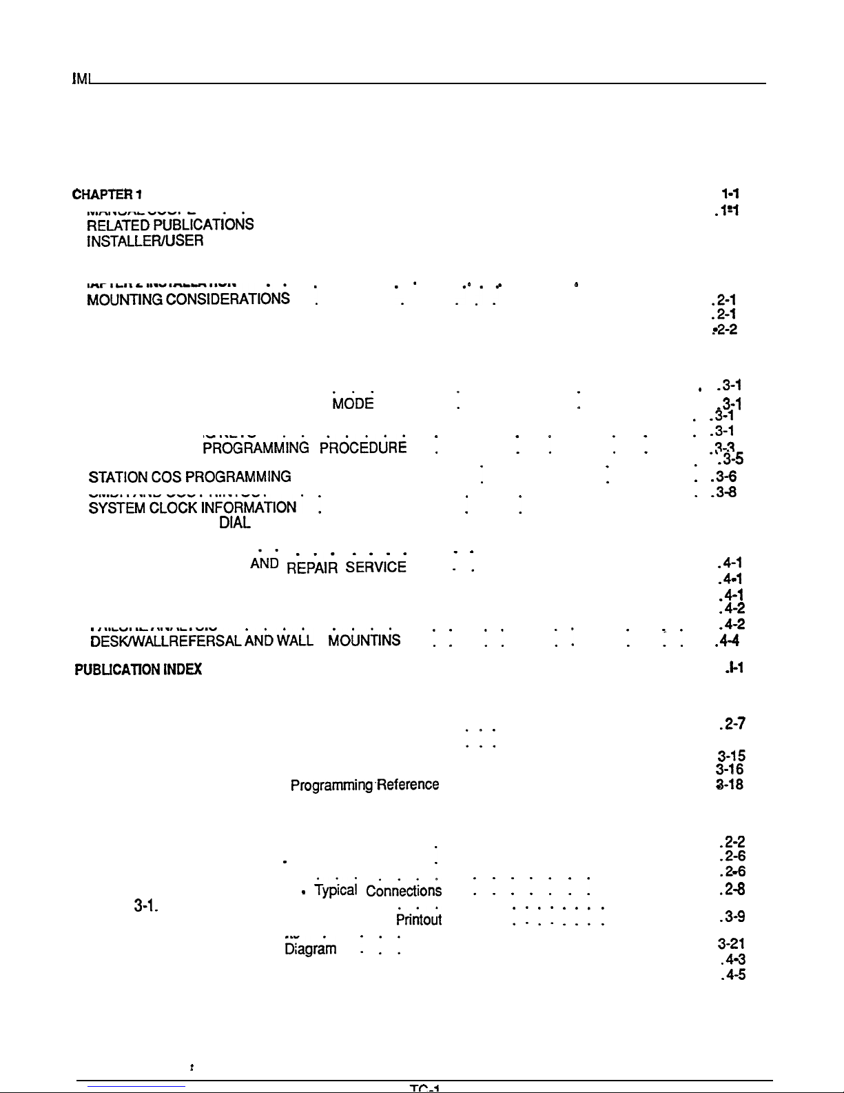
TABLE OF CONTENTS
Table of Contents
INTRODUCTION . . . . . . . . . . . . . . . . . . . . . . . . . . .
MANUAL SCOPERELATEDPUBLICATioN’S
. . . . . . . . . . . . . . . . . .
. . . . . .
REGARDING FCC RULES AND ‘REGULATIONS . . . . . . . . . . . . . . . . . l-l
CHAPTER 2 INSTALLATION
l
l .
. l
. . . .
. . . . . . . . . . . . . .
. . . . . . . .
.
MOUNTING PROCEDURE . . . . . . . . . . . . . . . . . . . . . . .
SYSTEM WIRING . . . . . . . . . . . . . . . . . . . . . . . . . .
CHECKOUT . . . . . . . . . . . . . . . . . . . . . . . . . . . . .2-9
CHAPTER3 SYSTEM PROGRAMMING . . . . . . . . . . . . . . . . . . . . . . . . 3-l
GENERAL INFORMATION
BASE LEVELPROGRAM ENTRY
CLASS OF SERVICE DEFAULT
. . . . . . . . . . . . . . . . . . . .
: : : :
: : : : : :
: : : : : . .
.
PROGRAMMING KEYS
SYSTEM COS
.
: : : :
:
: : :
:
: . .
LINE COS PROGRAMMING PROCEDURE
PROCEDURE . : : :
: : : : : :
: : : :
SMDR AND COS PRINTOUT
SYSTEM SPEED
CHAPTER 4 MAINTENANCE
TECHNICAL ASSISTANCE AND REPAIR SERVICE
PROGRAMMING . . . . . . . . . . . . . . . . . . . 3-12
...
FUSE LOCATION
: : : : : : :
FAILURE ISOLATION. : : : : : : : : : : : : : : : : : :
PAIRED STATIONS
.........................
: :
: : : : : : : : . 3-11
.......
..........................
.......
FAILURE ANALYSIS
.
:
: :
: :
:
:
2-l
Cl
..............................
LIST OF TABLES
Table 2-l. KSU to Station Wiring
Table 3-l. System COS Programming Reference .
. . . . . . . . . . . . .
. . . . . . . . . . . . . 3-13
Table 3-2. tine COS Programming Reference . . . . . . . . . . . . . . . . .
Table 3-3. Station COS Programming Reference
Table 34. Toll Restriction
. . . . . . . . . . . . . . . .
. . . . . . . . . . . . . . . .
Table 4-1. Station Pairing . . . . . . . . . . . . . . . . . . . . . . . . .4-3
LIST OF ILLUSTRATIONS
Figure 2-l.
Figure 2-2.
Figure 2-3.
Figure 2.4.
Figure
Figure 3-2.
Figure 3-3.
Figure 3-4.
Figure 4-l.
Figure 4-2.
Mounting Dimensions
External Signalling
Typical Connection
PA Connections
System Interconnection
Station Programming Keys
Station Message Detail Record
Typical COS Printouts
Programming Flow
. :
Failure Analysis Flow Chart
Station Wall Mounting Details
.. ..
...................................................
..............
.
....................
.
......
.....
Format.
.....
................
.3-2
3-l 0
Page 3

Introduction
CHAPTER 1
INTRODUCTION
MANUAL SCOPE
This publication contains installation, programming,
and maintenance information for the following Execu-
Tech electronic key systems and the associated
telephone equipment.
l
Model 0616X
manufacturing code
later
l
Model 0816X
all manufacturing codes
This system is fully protected, and therefore the instal-
lation does not require the services of an authorized
agent. However, the installation procedures detailed in
this manual should only be performed by individuals
familiar with general telephone installation procedures.
The end user may perform routine maintenance procedures. such as the following listed ones, but all other
servicing must be performed by factory authorized personnel
l
Place or replace any designation strips on the
face of the telephone stations.
l
Replace the line cord or handset coiled cord.
l
Replace complete stations and station handsets.
The handset is a special Comdial type. Other
handset types will not work properly.
Relocate the station when it is plugged into the
proper system jacks.
RELATED PUBLICATIONS
01-001, Compliance Requirements To FCC Rules
and Regulations Part 68 and 15
Handling Of Electrostatically Sensitive
Components
GCA 70-011, Station User’s Guide
GCA 70-044, Attendant Guide
INSTALLER/USER INFORMATION
REGARDING FCC RULES
AND REGULATIONS
This electronic key system complies with Federal Com-
munications Commission (FCC) Rules, Part 68.
The FCC registration label on the KSU contains the
FCC registration number, the ringer equivalence num-
ber, the model number, and the serial number or produc-
tion date of the system.
NOTIFICATION TO TELEPHONE COMPANY
Unless a telephone operating company provides and in-
stalls the system, the telephone operating company
which provides the lines must be notified before a connection is made to them. The lines (telephone num
bers) involved, the FCC registration number, and the
ringer equivalence number must be provided to the
telephone company. The FCC registration number and
the ringer equivalence number of this equipment are
provided on the label attached to the KSU.
company when final disconnection of this equipment
from the telephone company line occurs.
COMPATIBILITY WlTH TELEPHONE NETWORK
When necessary, the telephone operating company
provides information on the maximum number of
telephones or ringers that can be connected to one fine,
as well as any other applicable technical information.
The telephone operating company can temporarily discontinue service and make changes which could effect
the operation of this equipment. They must, however,
ment changes that would make the system incompatible.
INSTALLATION REQUIREMENTS
Connection of the electronic key system to the
telephone lines must be through a universal service
order code (USOC)
jack supplied by the
telephone operating company. If the installation site
does not have the proper outlet, ask the telephone corn
pany business office to install one. The correct outlet
jack for this system is a type RJ21X.
PARTY LINES AND COIN LINES
Local telephone company regulations may not permit
connections to party lines and win lines by anyone ex-
cept the telephone operating company.
TROUBLESHOOTING
If a service problem occurs, first try to determine if the
trouble is in the on-site system or in the telephone com-
pany equipment.
Page 4
Introduction
IM!
66-031
Disconnect all equipment not owned by the telephone
company. If this corrects the problem, the faulty equipment must not be reconnected to the telephone line until
the problem has been corrected. Any
that
causes improper operation of the telephone network
may require the telephone company to discontinue service to the trouble site after they notify the user of the
reason.
REPAIR
AUTHORIZATION
FCC regulations do not permit repairof customer owned
equipment by anyone except the manufacturer, their
the FCC. However, routine repairs can be made according to the maintenance instructions in this publication, provided that all FCC restrictions are obeyed.
RADIO FREQUENCY INTERFERENCE
The electronic key system contains incidental radio frequency generating circuitry and, if not installed and
used properly, may cause interference to radio and
television reception. This equipment has been tested
and found to comply with the limits for a Class A corn
puting device pursuant to Subpart J of Part 15 of FCC
Rules. These limits are designed to provide reasonable
protection against such interference when operated in
a commercial environment.
Operation of this equipment in a residential area may
cause interference to radio and television reception: in
which case the user is encouraged to take whatever
measures may be required to correct the interference.
If this equipment does cause interference to radio or
television reception, which can be determined by tum-
ing the equipment off and on, the user is encouraged to
try to correct the interference by one or more of the following measures: Reorient the television or’ radio’s
receiving antenna, and/or relocate the KSU, the individual telephone stations, and the radio or TV with
respect to each other.
If necessary, the user should consult the manufacturer
or an experienced radio/television technician for addi-
tional suggestions.
user may find the following
booklet prepared by the Federal Communications
mission helpful: “How to Identify and Resolve Radio-N
Interference Problems.” This booklet is available from
the Government Printing Office, Washington DC.
20402. Stock No. 004-000-00345-4.
RINGER
NUMBER
The REN of each line is 0.4B. The FCC requires the installer to
the total REN for each line, and
record it at the equipment.
l-2
Page 5
66-031
installation
CHAPTER 2
INSTALLATION
MOUNTING CONSIDERATIONS
l
The KSU should be attached vertically to any sturdy, flat, surface. It may be vertically rack mounted
if desired.
l
The KSU must be located within six (6) feet of a
proper electrical outlet. The power supply requires
a dedicated 117VAC
AMP circuit, with a third-
wire ground, supplied to a standard (NEMA
electrical outlet.
l The distance between the KSU and the
FCC requirements. A nominal distance of 7 feet is
recommended.
.
The mounting location must be secure and dry and
have adequate ventilation. The temperature range
of the location must be within 32-122 degrees F
50 degrees C), and the relative humidity must be
less than 90 percent non-condensing.
.
If the mounting surface is damp or if it is concrete
or masonry material, a backboard must be attached
to the mounting surface to be used for KSU mounting. Suitable mounting backboards are available
commercially or can be constructed out of
plywood cut to size.
l
Tools and hardware reauired for mountina include:
2.
Fasteners
wood screws
x 1
round
head), toggle bolts, or wall anchors
Screwdriver -to match fasteners
Electric drill
if prepared holes are required
Connecting tool
for fastening wires to a type-
66 connector block.
Crimping tool
for 623-type modular plugs
MOUNTING PROCEDURE
Unpack, and carefully inspect all equipment for
shipping damage. Notify the shipper im-
mediately of any damages found. Verify that
the packages contain all parts and accessories
needed for proper installation and operation.
If a backboard is required at the mounting loca-
tion, attach it securely to provide a stable
mounting surface for the equipment.
3.
4.
5.
6.
scale mounting template is supplied in the
packing box. Hold ortape it to the mounting sur-
face, and mark the location of the mounting
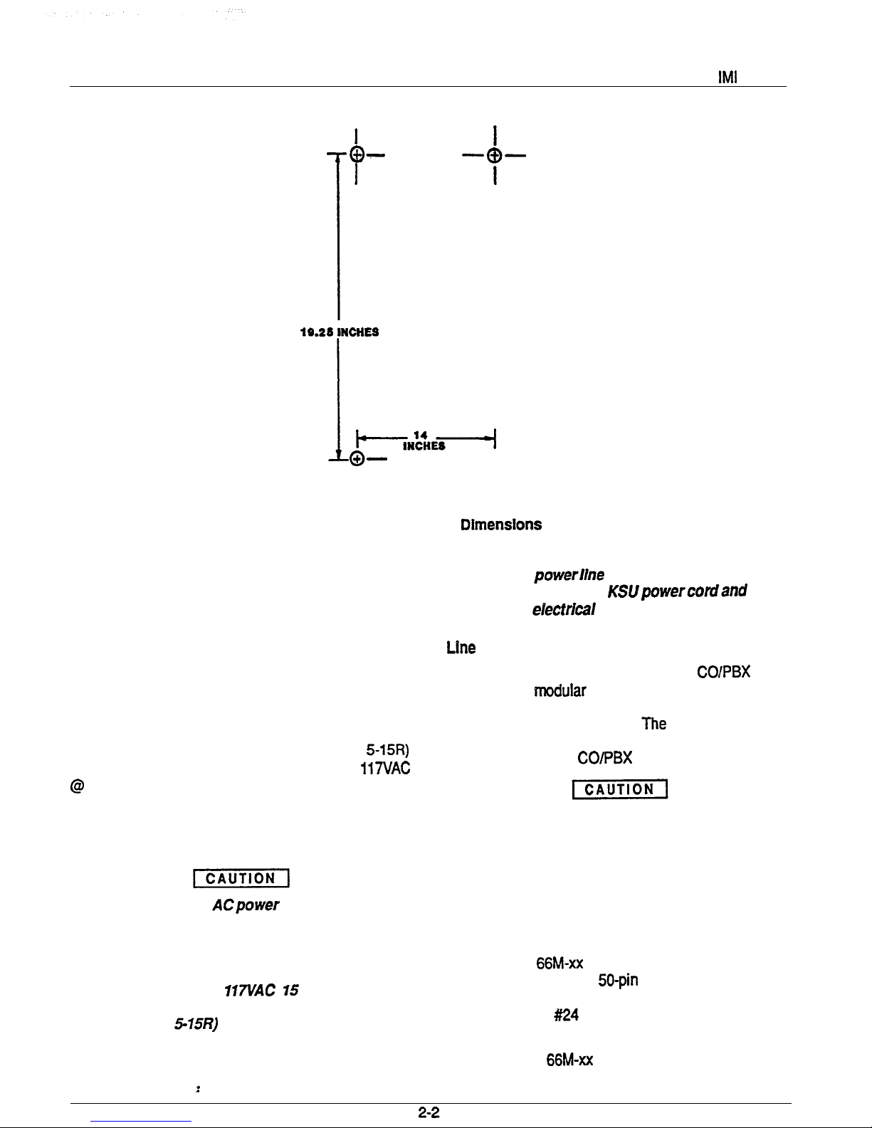
holes on the mounting surface as they are located on the template. The mounting dimensions are shown on Figure 2-l . .
size to accommodate the hardware being used.
If necessary, prepare these holes with inserts,
anchors or other attachment devices as dic-
tated by the type of mounting surface.
Attach the KSU to the mounting surface with
four (4) screws installed through the KSU
mounting flange and into the mounting surface
holes. Note that the flange holes are elongated
with an enlargement at one end. This feature
allows the mounting screws to be partially installed in the mounting surface before the
cabinets are hung on them.
Place the individual telephone stations as
desired and in keeping with accepted industry
and office standards. Currently produced 8
tine Keysets can be wall mounted if necessary
as they are
reversible. Currently
produced keyset models include:
l
l
l
l
l
l
Refer to Chapter 4, Maintenance, for instructions in
preparing a desk/wall reversible station for wall mounting.
Any previously produced keysets which may currently
still be in service can also be wall mounted if necessary.
Use a wall mounting bracket (part number 701032-056)
for this purpose.
Page 6
Installation
---o--
l
I
Figure 2-1. Mounting
SYSTEM WIRING
System cabling may be routed concealed or visible as
the installation location requires, Good engineering
practices must be observed
and
all applicable building
codes must be adhered to.
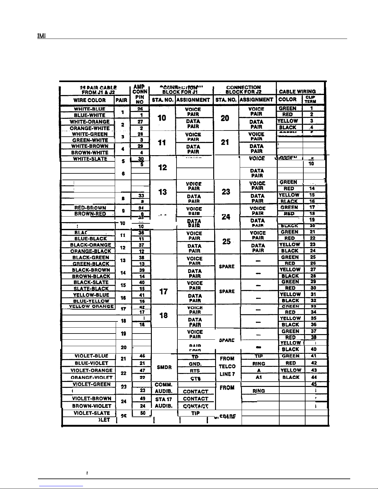
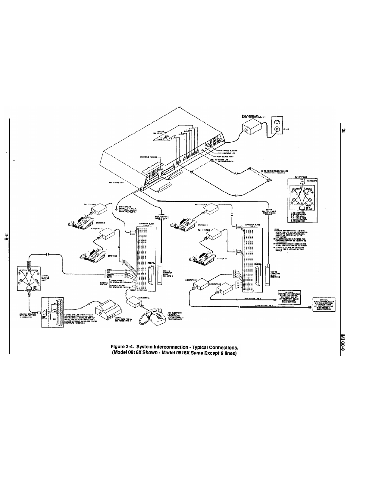
Table 2-l and Figures 2-2
through 2-4 illustrate the system wiring and connection
points for the key system.
AC Power Connection
The AC power is applied to the system by connecting
the AC power cord to the standard (NEMA
electrical outlet which supplies the dedicated 117VAC
The following precautions should be taken to help
prevent damage to the system which could be caused
by an electrical over-voltage condition.
l
Do not connect the ACpower cord until the installation has been checked per the SYSTEM
CHECKOUT instructions given at the end of
this Chapter.
l
Employ a dedicated lVL!AC
AMP circuit,
with a third-wire ground, supplied to a stand-
ard (NEMA
electrical outlet for the
AC
power connection.
l
A plug-in, powerline surge protectof should be
installed between the KSUpowercordand the
AC power eiectrkai outlet.
The KSU interface connections for the COlPBX lines
are individual
jacks. Wiring between the KSU
connectors and the demarcation point connectors is via
standard modular line cord.
maximum allowed
tip/ring loop resistance is 1900 ohms from the KSU
modular jack to the CO/PBX equipment.
To help Insure that foreign voltages, which could
appear on the CO lines, do not damage the system,
verify that gas discharge tubes orsimiiarprotection
devices are installed, and properly grounded, in all
connected CO lines.
Statlon Connection
Connections between the KSU and the stations are typically via type 66M-xx connector blocks which are cable
connected to the KSU
male connectors. The
maximum distance allowed from the KSU to a station is
1500 feet using #I24 gauge, twisted-pair cable.
.
If spare conductors exist in the cables that are run be-
tween the KSU 66M-xx connector block and the station
Page 7
Installation
jacks, it is a good practice to connect them to earth
ground. Doing this may help prevent them from induc-
ing radio frequency and/or AC interference into the
tern
The polarity between the individual wires in a particular voice or data pair is not critical; however do
not connect the voice circuits to the data
Cable
Each cabinet-mounted
male connector is
equipped with a retaining clip. This clip is designed to
secure the matted connection once it is made. The clip
does this by snapping into a slot on the cable-mounted
connector when it is pressed together with the cabinet-
mounted connector. This retaining clip must be pulled
back slightly to un-snap it before the connectors can be
separated.
Console Connection
The optional DSS/BLF console may be installed at any
station port to work in conjunction with a companion station connected to the adjacent port (e.g.; port 10 for station and port 11 for console).
The installed distance limit between the KSU and a con-
sole is the same as that specified for a regular station.
Connect all four wires (voice pair and data pair) of the
console cable to the station connector block.
The voice pair connections of the console can be used
simultaneously to enable a PA port function. Refer to
the paragraph in this chapter headed Area Paging In-
terface
Station PA Port. Per that discussion, wire a PA
connector block clip terminals. Use an audio matching
transformer, as discussed in the referenced paragraph
and Figure 2-3, to provide isolation. If an enable signal
is required with the particular PAequipment being used,
the console and PA equipment connections are limited
to station ports 23 and 25.
The DSS/BLF console port must be programmed as a
before console operation can take place. The console
port must be also programmed as a PA port if a PA
amplifier has been connected to the voice pair as part
of the system.
Busy Lamp Field Stations
An optional keyset is available which is equipped with
a 14 station Busy Lamp Field (BLF). Up to eight BLF
stations can be connected to the system. A BLF station
can be connected to any odd or even station port in the
system per the following guidelines.
The installed distance between the KSU and the
BLF station must be limited to 1000 feet or less.
The data-line paired station port cannot be used as
a BLF station connection or as a regular station
connection. Data-line pairing is: 1 O-l 1,12-13,
The overload paired station port cannot be used as
a BLF station connection but can be used as a
regular station connection. Overload pairing is: 1
12, 1%13,14-16,15-17, 18-20,19-21,22-24, and
23-25.
A port, paired in either manner with a BLF station,
can be used as a PA port if desired.
Power Failure Station Connection
The system provides a tip and ring-pair connected to
line 1 as an emergency power failure circuit. This power
failure pair is available at clip terminals on connector
block J-l as detailed on Table 2-l and Figure 2-4. A
power failure pair is only active durfng a commercial
AC
power failure. An industry standard, single-line
telephone, such as a Comdial model 2500-xx, can be
connected to a power failure pair and used to provide
communications capability until the AC power to the
system is restored.
A-Lead Control Device Connection
The KSU can detect an A-lead
(A
and Al) control sig-
nal when it is applied to lines 7 and 8. An A-lead con-
trol device can be bridge-connected to these lines via
clip terminals on connector block J-2 as detailed on
Table 2-1 and Figure 2-4.
Data Device Connection
When a serial data printer is used for SMDR and COS
printout, connect it to clip terminals on connector block
J-l as detailed on Table 2-1 and Figure 2-4.
The distance between the device and the KSU can be
up to 500 feet in a quiet electrical environment.
Shielded cable may be required at some sites for long
runs. For longer distances, a limited distance modem
must be used to relay the data communications between the KSU and the data device.
When preparing a cable for connection to a data device,
refer to the manufacturer’s manual for the equipment
being interfaced, and make the following wiring connections:
Wire the KSU RD line (data from printerto wmmon
equipment) to the device TD (transmit data) output
pin,
2-3
Page 8
Installation
Wire the KSU TD (data to device from KSU) pin to
the device RD (receive data) pin.
Wire the KSU SG (signal ground) pin to the device
SG (signal ground) pin.
Wire the KSU CTS (clear-to-send status from
device to KSU) pin to the device FITS (request-to-
send) output pin.
NOTE: The
a
voltage,
respect to signal ground, in order to send data.
If required, wire the KSU
(request-to-send
status signal from the KSU to the device) pin to the
device DSR (data-set-ready) input pin.
If required, wire the KSU PG (protective ground)
tine(s) to the device protective ground pin(s).
Data Format
Configure the data device to match the following data
format and to receive data at the baud rate that is set
by COS programming.
l
fixed
l
Baud rate of 110 baud (defautt)
can be changed
to 300 baud through class of service programming.
System Grounding
It is required that a grounding wire, separate from the
three wire AC line cord, be used. A ground stud is to-
insulated, solid copper wire between the ground stud and
a reliable earth ground such as a metal cold water pipe
or a building frame ground.
Common
and Auxiliary Station interface
Two sets of relay closure drycontact points are available at the J-l station connector block.
l
One set (J-l connections) provides a dry-contact
closure whenever any of the
lines,
connected to the KSU, ring.
l
The other set provides a dry-contact closure whenever system station 17 rings.
These contact closures track the ringing pattern in both
cases. The contacts are closed during the ringing
period and are
open
during the silent perfod.
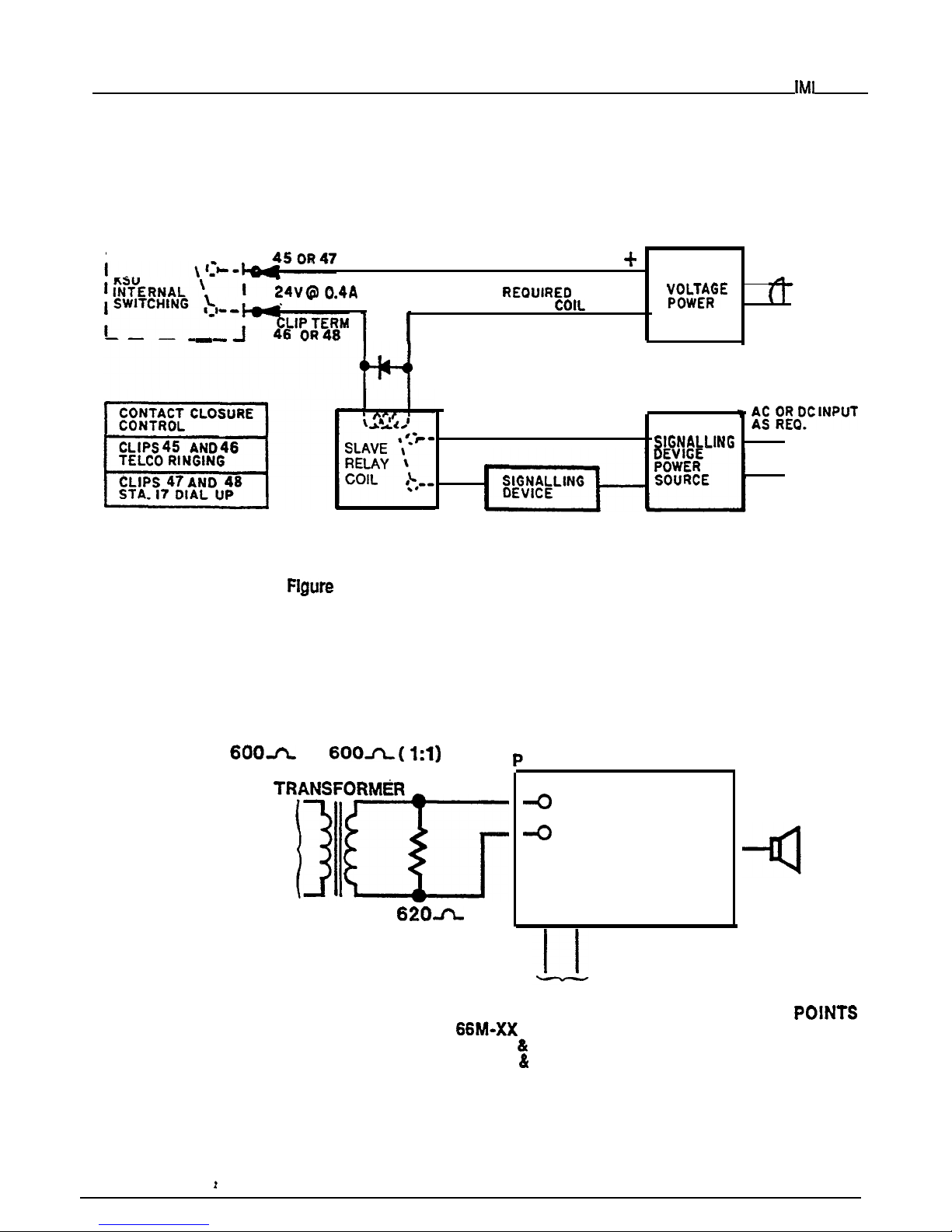
A typical connection is illustrated in Figure 2-2. Refer
to the paragraph headed Area Paging Interface for a
discussion for using these terminals in the
paging function.
Do not exceed a
amp at 24 volts
at 48 volts)
load on these control terminals.
If the load
ments exceed thls
connect the load through
an external slave relay.
DO NOT CONNECT THESE
CONTROL TERMINALS DIRECTLY TO THE 117VAC
LINE.
24
Page 9

Installation
Area
Paging
Interface
Station PA Port
A station port can be configured by class of service
programming to be a PA port. As a PA port, it can be
used to couple a station voice path to an external device
(see Chapter 3 for programming details).
The audio input of an external paging amplifier can
be connected to the audio pair of the station port as
illustrated in Figure 2-3.
The audio input connection must be isolated with a
600 ohm to 600 ohm audio matching transformer.
Terminate the audio input of the paging amplifier
with a 620 ohm (nominal value) resistor.
If station port 23 is programmed as a PA port, the
Common Audible contact points are automatically
reconfigured as PA enable terminals. The contact
closure now occurs when PA station 23 is dialed.
The normal common audible function, as discussed
previously, is disabled as long as station 23 is a PA
station.
If station port 25 is programmed as a PA port, the
Auxiliary Station Interface (station 17 audible) con-
tact points are automatically reconfigured as PA
enable terminals. The contact closure now occurs
when PA station 25 is dialed. The normal auxiliary
station interface function, as discussed previously,
is disabled as long as station 25 is a PA station.
Area Paging Interface - Llne Port
A fine port can be configured by COS programming to
be an AUXILIARY port. As an AUXILIARY port, it can
be used to couple a station voice path to an external
device. This is done from any station with that tine ap-
pearance by pressing the proper line key to select the
AUXILIARY port.
dialed through the AUXILIARY port as needed.
l
The audio input of an external paging amplifier can
be connected to the tip and ring leads of the line
l
The audio input connection must be isolated with a
600 ohm to 600 ohm audio matching transformer.
Terminate the audio input of the paging amplifier
with a 620 ohm (nominal value) resistor.
A DTMF tone select, zone-paging amplifier can be
employed if desired. If used, the zone-select code must
be dialed after the AUXILIARY port line select key is
pressed.
If music on hold is to be part of the system, connect a
KX registered music source to the KSU input jack
(phono jack) provided for this purpose. The impedance
of this input is approximately 500 ohms. Level adjust-
ment of the music source may be necessary. This may
be done during system checkout.
2-5
Page 10
Installation
l----1
CLIP TERM .
OUTPUT AS
LOW
MAX
BY
RELAY
SUPPLY
AC
-VOLTAGE CLAMPING DIODE
RECOMMENDED
.
0
0
2-2. External Signalling-Typical Connection.
TO
AUDIO
TO KSU STATION
PORT 23 OR 25 IF
ENABLE IS REQUIRED
OR TO ANY UNUSED
STATION PORT IF
ENABLE IS
NOT REQUIRED.
A SYSTEM
AUDIO
INPUT
ENABLE INPUT
QQ
TO KSU EXTERNAL CONTROL CONNECTION
ON
CONNECTOR BLOCK.
l CLIPS 45
46 FOR STATION PORT 23 PA ENABLE
l CLIPS 47
48 FOR STATION PORT 25 PA ENABLE
Figure 2-3. PA Connections.
2-6
Page 11
Installation
Table 2-l.
KSU To
Station Wring.
I
l
I
I
STATION
GREEN 5
RED
6
YEUDW 7
BLACK 6
.
SLATE-WHITE
RED-BLUE
31
BLUE-RED
6
RED-ORANGE
32
.
ORANGE-RED
7 7
RED-GREEN
,
GREEN-RED
VOICE
PAIR
DATA
PAIR
22 .
PAIR
RED
YEUOW 11
BLACK 12
l *
14
_____
RED-SLATE
__
YEUDW
I
SLATE-RED
:K-BLUE
15
16
ORANGE-YELLOW1
YELLOW-GREEN ,6
43
GREEN-YELLOW
YELLOW-BROWN.
U
BROWN-YELLOW
19
19
I
YELLOW-SLATE
.
45
DATA
SLATE-YELLOW
20
,
SPARE
I
I
29
I
48
CONTACT
TIP GREEN
GREEN-VIOLET
TELCO
RI
RED
46
LINE6
A YELLOW
47
Al
BLACK
46
I
I
POWER
GREEN
49
SLATE-VIC RED
56
--
I 25
FAIL
RING
2-7
Page 12
Page 13
Installation
CHECKOUT
Check the KSU and telephone installation for proper
operation by performing the following actions.
Resistance
Check
Make the following resistance measurements at the Sta-
tion connector blocks under the following conditions.
l
AC power cord disconnected from electrical outlet.
l
KSU connected to station connector blocks.
l
Stationswired, and wiring punched downon blocks.
l
Bridging clips removed from blocks to isolate sta-
tions from common equipment.
1.
Measure the resistance of each installed sta-
tion
and wiring from the station side of the con-
nector blocks. Resistance values will vary with
cable length and station type but should be
within the following limits. Readings which are
or station problem.
2.
VOICE PAIR:
(40 OHMS MIN.-150 OHMS MAX.)
DATAPAIR:
(0.3 OHMS MIN.-100 OHMS MAX.)
Measure the resistance of the KSU and cables
from the KSU side of the station connector
blocks. Resistance values should be within the
following limits.
MEASURFD PAIR
VOICE PAIR
DATA PAIR
Voltage
Check
MEASURED KSU
40-50
0.3
0.5
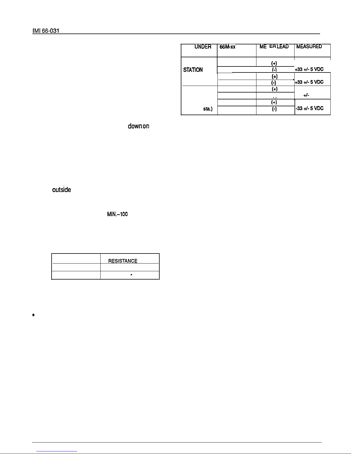
Make the following voltage measurements at the station
connector blocks under the following conditions:
Bridging clips installed
l
AC power connected to the common equipment
Measure the voltage across one voice line and one data
line and then across the other voice line and the other
data line for each even and odd station. The measured
voltage must be as follows:
UNIT
I
LtAD MEASURtD
TEST
CONNECTION POLARITY VOLTAGE
TYPICAL EVEN
Voice 1
I
Data 3
.
I
(Repeat for
each even sta.)
TYPICAL ODD
STATION
(Repeat for
each odd
voice2
Data 4
Voice
5
Data
7
Voice 6
Data 8
I-) -335VDC
Variant readings can indicate a possible wiring, station,
or common equipment problem.
General Check
1.
2.
3.
Check the red light emitting diode (LED) sys-
tem status indicator.
Be sure that it is on steady. If it is off or flashing, disconnect and reconnect the AC power
plug. If the indicator is still not on steady, refer
to the Failure Analysis Flow Chart found in
Chapter 4.
Refer to the station User’s Guide for operating
information.
Perform a general operational test of the sys-
tem by exercising the systemfeaturesfrom sta-
tion port 10 or 11. Operational parameters are
per the system default conditions as detailed in
Chapter 3 until COS programming is per-
formed.
Once the basic system is verified as operational, perform the COS programming.
:
2-9
Page 14
CHAPTER 3
SYSTEM PROGRAMMING
GENERAL INFORMATION
Class Of Service (COS) programming consists of
setting the Class Of Service (COS) operating conditions. COS programming is divided into the following three major categories: System COS, tine
COS, and Station COS.
All COS programming commands must originate at
station 10. No COS programming commands can
be accepted from any other station connected to the
system. COS programming causes station 10 to
default to a square condition (line select key 1
selects line
key 2 selects line 2, etc.). It is recom-
mended that station 10 always remain in a square
conditionto avoid possible programming confusion.
COS programming does not require that a sequential process be followed once the base level
program entry mode has been established except
where noted herein.
The system defaults to preset characteristics when
it is initially powered up or whenever programmed
to do so. If the default characteristics, or any other
previously set characteristics, are satisfactory,
those portions of the programming sequence may
be omitted.
Prior to taking any programming action, record the
system, line and station COS conditions on Table
ter). Also, record all toll restdction requirements on
Table 3-4.
THE PROGRAMMING STEPS MUST BE PER-
FORMED WITH LESS THAN 17 SECONDS OF
DELAY TIME BETWEEN KEYSTROKE OPERA-
TIONS. A delay of longer that 17 seconds causes
the KSU programming mode to time out.
Flgure 3-3 found at the end of this chapter provides
a quick-reference flow diagram of the class of ser-
vice programming requirements.
Programming is the same for both the model 0616X
and 0816X key systems. The only difference be-
tween these two models is the number of lines
which each serves (six or eight).
BASE LEVEL PROGRAM ENTRY MODE
The first step in a COS programming sequence is to
enter the base level programming mode. Once in
this mode, COS can be set as desired.
2. Press the following keys in sequence:
7 4 6.
The dial tone stops and a tone burst sounds to in-
:
3.
entered.
Press
The dial tone will return as a confirma-
tion that the base level mode is active.
CLASS OF SERVICE DEFAULT
The system can be defaulted to a standard class of
service per the following procedure.
1. Press
2.
Press the following keys:
7 4 6
# 0
3. Press MONITOR.
The following system default conditions are set:
All lines are DTMF
Voice signalling attempted first when inter-
com call is made
sec. pause time
2 sec. dial tone recall time
30 sec. recall from hold
All lines private
All lines are CO lines
No toll restriction set
300 msec. held call abandon time
No ringing line preference enabled
No prtme line is chosen
port is disabled
PA port is disabled
No delayed ringing enabled
No access denied
No origination denied
No automatic privacy released
Day and night ringing patterns set as follows:
station 10,
7, and 24 all lines
System-wide, all call paging in zone D
Printer port set for 110 baud data rate
Line select keys l-n selects lines l-n
(squared pairing)
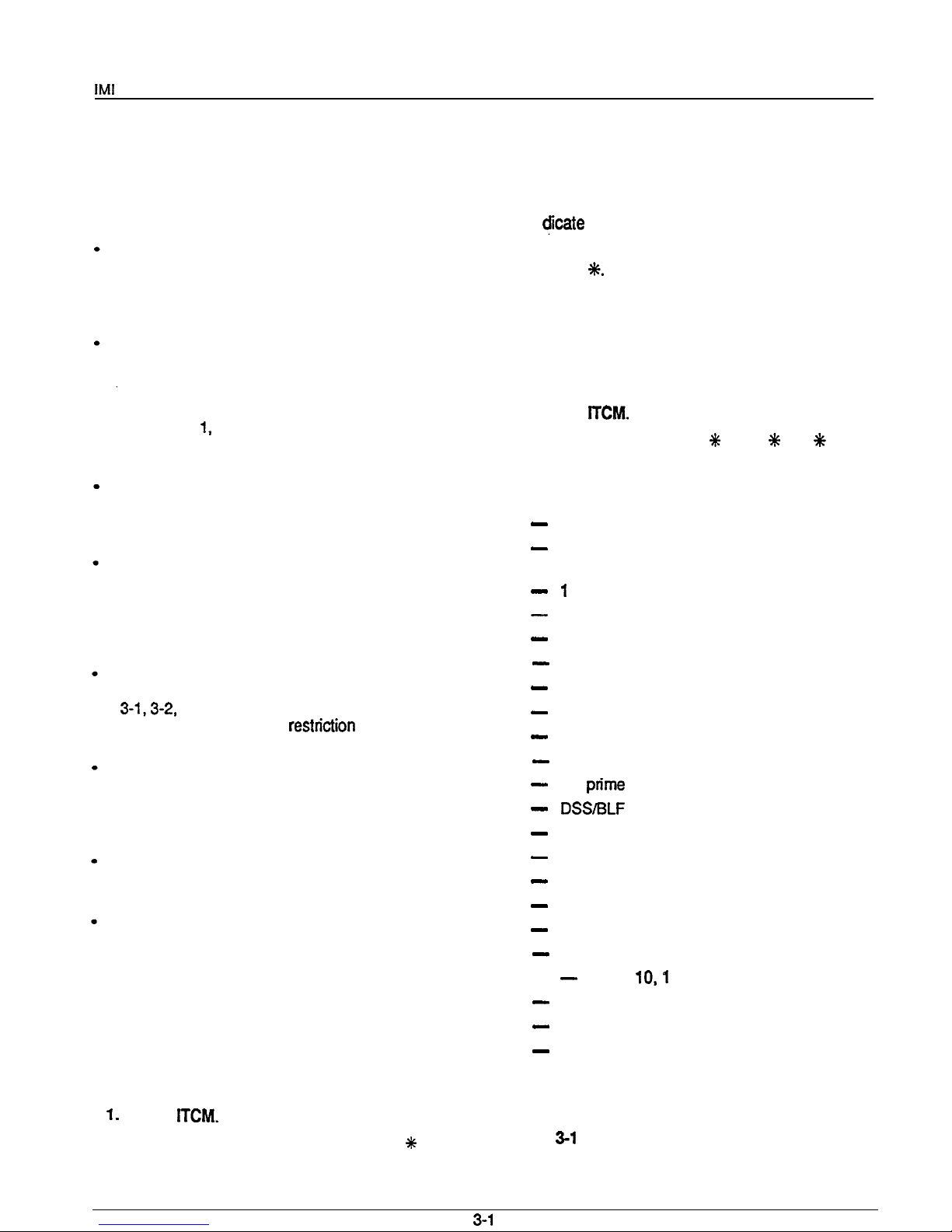
PROGRAMMING KEYS
Figure
illustrates the programming keys called
out in the following procedures.
Page 15
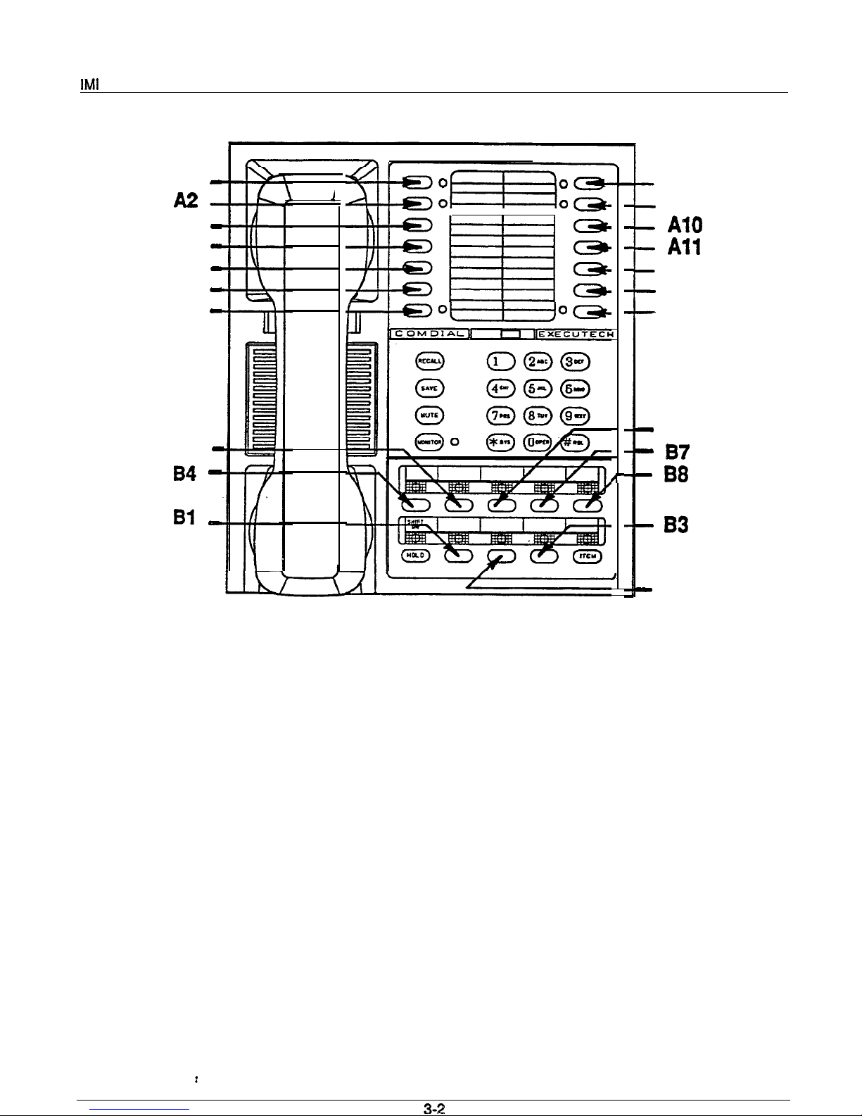
Al -
A3
A4
A5
A6 -
A7 -
B5
0
0
0
0
0 0
0
0
Figure 3-l. Programming Key Layout
A8
A9
A12
Ad3
Al4
B6
B2
Page 16
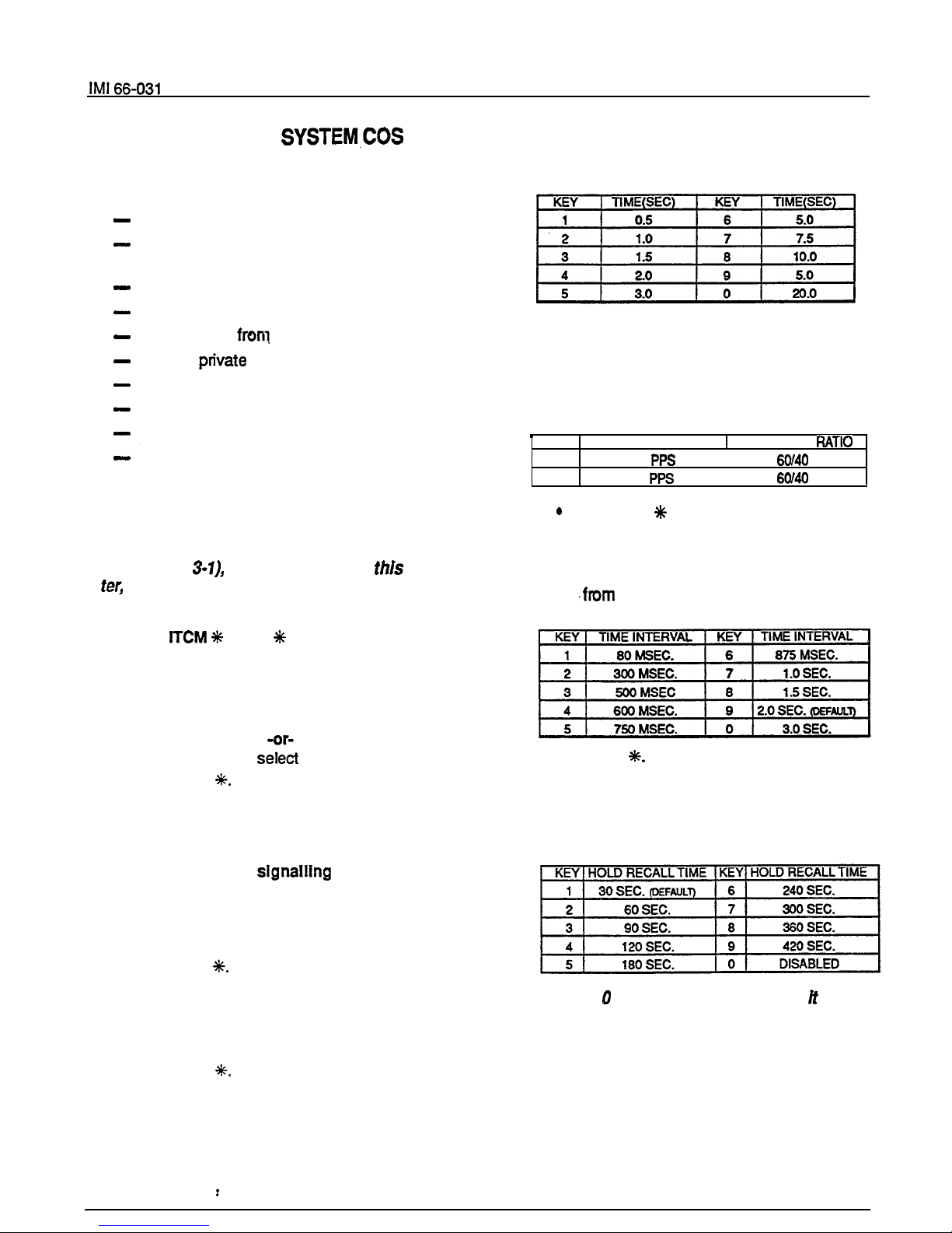
SYSTEM DEFAULTS
All lines are DTMF
Voice signalling attempted first when inter-
com call is made
1 sec. pause time
2 sec. dial tone recall time
30 sec. recall from hold
All lines prfvate
All lines are CO lines
No toll restriction set
Printer port set for 110 baud data rate
2 sec. automatic pause insertion wait time
PROCEDURE
NOTE: Before performing this procedure, turn
to the System COS Programming Reference
Chart (Table
locatedat the end of this chap
and record all system COS requirements on
it.
1. Press
7 4 6
(base level entry)
2.
Select the
PULSE/TONE
or TONE ONLY dialing
system default characteristics.
l
Press #. Dial tone will stop.
l
Press 0 to select
TONE ONLY.
l
Press 1 to
PULSE/TONE.
l
Press
Dial tone will return.
NOTE: In addition to setting the dialing mode,
the above action defaults the system, line and
station COS.
3. Select Intercom
first performed
when intercom call is placed.
l
Press Al3 for tone signalling.
-or-
.
Press Al4 for voice signalling.
l Press
4.
Select time interval for programmed pause.
l
Press 4. Dial tone will stop.
l
Press key to select time interval per
chart. Tone burst confirms selection.
l
Press
Dial tone will sound.
5. Select pulse dial operatlng characteristics.
l
Press 5. Dial tone will stop.
l
Press keypad key to select operating
characteristic per chart. Tone burst confirms selection.
KEY PULSES PER SECOND
BREAK/MAKE
1
10
I
2
20
Press the % key. Dial tone will sound.
6.
Select
flash/dial tone recall time
interval.
l
Press 6. Dial tone will stop.
l
Press keypad key to select time interval
l
Press
Dial tone will sound.
7.
Select
hold
recall
time
interval.
l
Press 7. Dial tone will stop.
l
Press keypad key to select hold recall interval from chart.
NOTE: The
program selection makes
possible for an exclusive hold condition, when set
at a station, to place a line on a pennanent hold
thaf cannot be released at any other station.
3-3
Page 17

System Program-
l
Press
Dial tone will sound.
Select
toll restriction table entries. Refer to
programming table (Table 3-4) to preselect entry
requirements.
l
Select table with memory key. The dial
tone will stop when the selection is made.
AlAl
11
A5A5 55
A2A2 22 A6A6
66
A3A3 33 A7A7
77
A4A4 44 A8A8
88
l
Select
mode of table
with keypad key.
Tone burst conforms selection.
l
Select
entry line on table
with memory
key. Action clears any current entry and
causes continuous busy tone to sound.
l
Dial
number for entry line. Press
key
to enter “match anything” digit. Tone
burst sounds after each key is pressed.
NOTE: An entry line can contain a maximum of
16 digits.
When the maximum number of digits
are entered, the system sounds a fast
tone, and steps to the next entrypoint on a table
or to the next table.
If less than sixteen digits are entered on
line, select next entry location with
memory key.
l
Repeat procedure for each desired toll
restriction table.
NOTE: Select an
line even if no input is re-
quired.
This action insures that any previous
entry is cleared. Select a table and then select
each line in the table to clear the table of
entries.
Do not dial any numbers after the entry
line selections.
l Press
9.
Program
data speed baud rate
for printer port.
l
Press 3 to set data speed of 300 baud.
-or-
*
Press 0 to set data speed of 110 baud
l Press
10. When the system stores a dialed number for later
the user waits a period of time between digits.
(The length of the stored pause was programmed
in step 4.) To program
length of time to
is inserted, proceed as follows:
l
Press
7 4 6
to enter program-
ming mode.
l Press RECALL..
l
Press keypad key 1 to set wait time to
750 milliseconds.
-or-
*
Press keypad key 2 to set wait time to 2
seconds.
l Press
11. Press
to exit system COS program-
ming mode.
.
3-4
Page 18

System Programming
LINE COS PROGRAMMING PROCEDURE
LINE DEFAULTS
All lines private
All lines are CO lines
No toll restriction Set
Dialing mode is tone only
300
msec.
held call abandon time
5.
6.
PROCEDURE
NOTE: Before performing this procedure, turn
the Line COS
Reference Chart
(Table
located at the end of this chapter,
and record all line COS requirements on it.
7.
l Press
7 4 6
The dial tone
8.
will sound.
Press keypad key to restore after hold is aban-
doned.
KEY TIME INTERVAL
8
MSEC.
9
300 MSEC.
Repeat procedure from step 3 for next fine to be
programmed.
2.
Choose
privacy
status
of each line.
NOTE: There are a
of
lines
be
l
Press 8. Dial tone will stop. This action
programmed on a model 0616X system and a
initializes all lines as private. This condi-
maximum of eight lines on an 0816X system-
tion is also system default value.
9.
l
Press line select key of each line which
Press& MONtTOR to exit line COS programming.
is to be non-private.
Dial tone will sound.
Press memory
keys to assign toll restriction
tables to
KEY
TABLE
KEY
TABLE .
Al
1
A6 6
A2
2
A6
6
A3 3
A7 7
A4
4 A8 8
Specify dialing mode per
chart
with keypad key.
A tone burst will confinn selection.
A tone burst sounds after each selection
for confirmation.
l
Press
Dial tone will sound.
Press tine select key (program keys Bl-B6 for
model 0616X or
-B8 for model 0816X) for line
to be programmed. Dial tone will stop.
NOTE: Selecting a line forprogramming clears
all assigned toll restriction tables.
4. Specify line type per chart with keypad key. Atone
burst will confirm selection.
3-5
Page 19

STATION COS PROGRAMMING PROCEDURE
System Programming
STATION DEFAULTS
No ringing line preference enabled
No prime line is chosen
DSS/BLF port is disabled
PA port is disabled
No delayed ringing enabled
No access denied
No
denied
No privacy released
Day and night ringing patterns set as follows:
station 10, 17, and 24 all lines
System-wide, all call paging in zone D
tine select keys 1 -n selects lines 1 -n
(squared pairing)
PROCEDURE
NOTE: Before
this procedure, turn
to the Station COS Programming Reference
Chart (Table 3-3), located at the end of this chap-
ter, and record ail station COS requirements on
1.
Enter the base programming mode:
l
Press ITCM
7 4 6
Dial tone will
sound.
2.
Press a two-key sequence on keypad to choose
station port for programming (i. e.,to choose station 11 press 11). Tone burst sounds to confirm
selection. Improper selection results in dial tone.
NOTE: Station port selection defaults the foi-
lowing features:
enable,
port
enable, prime line selection, and ringing line
preference enable. Pius, toil restriction table
assignments are disabled.
3. Configure port as DSS/BLF console
port
(if con-
sole port is required).
.
Press RECALL. Tone burst sounds to
confirm selection.
l
Skip this step if DSS/BLF console is not
installed at station port currently being
programmed.
l
If enabled, do not proceed beyond this
step unless port is also to be
programmed as PA port.
4.
Configure port as
PA
(if PA port is desired).
Press 9. Tone burst confirms selection.
:
Skip this step if PA port is not desired.
l
Do not proceed beyond this step if PA
port selection
is
made.
5. Choose prime line or prime
Tone
burst confirms selection.
l
Press tine select key for line desired.
-or-
* Press
NOTE: if more than one iine selection key is
pressed, the last one pressed selects the
cep ted prime line.
6. Enable
ringing line preference.
l Press 1.
7. Press memory keys to assign toll restriction
tables to station.
l
At this point, there are no toll restriction
tables assigned.
l
Tone burst confirms each selection.
Skip to step 16 after programming the toll restric-
tion table assignments unless other station COS
programming
must be performed.
l
is recommended that programming steps
8-14 be performed in the order that they
are presented below. In steps 8-14, the
whenever the program selection key is
pressed. This default value is overridden
by the subsequent programming action.
l
During subsequent reprogramming of a
station, any step, controlling a feature
that does not need to be reprogrammed,
can be skipped over thus leaving the current COS condition intact. It is not necessary to return to the base programming
mode to shift from one programming step
to another except when performing step
15. Program step 15, which sets the line
appearance to key assignment, must be
followed by a return to base level
programming (press
8. Program
direct ringing
assignments.
NOTE: A
may be programmed for direct
ringing or delayed ringing but not for both ring-
3-6
Page 20

System Programming
features.
dtrect rtngtng
setected after
delayed rtngtng
selected, delayed rtngtng wttt
be disabled.
Press 2 for direct tinging.
Tone burst
sounds to confirm.
condition of no ringing enabled
now set on all iines.
Press line select
key
(program
keys
B6 for 0616X and
-B8 for 0816X)
for
each line on which direct ringing
is
desired. Tone sounds after each selection.
9. Program
delayed ringing
assignments.
l
Press 3 for delayed tinging. Tone burst
sounds to confirm.
l
Press Iine select key (program keys
B6 for 0616X and
-B8 for 0816X) for
each line on which delayed n’nging is
desired.
l
Tone sounds after each selection. Delay
time is 15 seconds.
10. Choose
access
status.
Press 4. Tone burst sounds. Defauft
condition of access not denied set on all
lines.
l
Press line select key (program keys
B6 for 0616X and
-B8 for 0816X) for
each line on which access is to be
denied.
l
Tone burst sounds after each selection.
11. Program
call origination denled
status.
l
Press 5. Tone burst sounds. Default
condition of call origination not denied set
on all lines.
l
Press line select key (program keys
B6 for 0616X and
-B8 for 0816X) for
each line on which call origination is to
be denied. Tone burst sounds after each
selection.
12.
Set access to
privacy release.
l
Press 6. Tone burst sounds. Defauit
condition of no access to privacy release
set on all lines.
l
Press line select key (program keys
B6 for 0616X and Bl -B8 for 0816X) for
each line on which access is to be
denied. Tone burst sounds after each
selection.
13. Set night ringing status.
l
Press 8. Tone burst sounds. Defauit condition of no night ringing
be set on all
lines.
Press line select key (program keys
B6 for 0616X and
-B8 for 0816X) for
each line on which night ringing is
desired. Tone burst sounds after each
selection.
14. Set all-call and zone paglng
capability. Default
value is all-call at all stations in system.
l
Press 1. Tone burst sounds. Clears sta-
tion from paging zones A, B,
and C.
l
Press ITCM to clear station from atl-catl
(if required).
l
To assign reception by zone,
l
Press line select key for zone A
l
Press tine select key 2 (B2) for zone B
l
Press line select key 3 (B3).for zone
C.
l
Press line select key 4 (84) for all-call (if
it was previously cleared).
l
To enable origination by zone,
l
Press line select key 5 (B5) for zone A
.
Press line select key 6 (B6) for zone B
l
Press line select key 7 (B7) for zone C
l
Press line select key 8 (B8) for all-call (if
it was previously cleared).
NOTE:Step
tmmedtapty fottowedby
a
to bass level.
15.
Set
appearance to key assignment if cur-
rent settings are not correct. System default configures line appearance to key assignment so that
ment has tines l-6 assigned to keys Bl-B6 for
model 0616X, and lines l-8 assigned to keys
B8 for model 816X.
l
To re-assign line/key configuration,
l
Press 7. Tone burst sounds.
l
Press Gne key
Tone burst
sounds.
l
Press keypad key
for
number of line
6). Tone burst sounds.
l
Press next line key and keypad key com-
bination. Repeat for each line. All iine
select keys can be programmed to select
same tine if such a condition is desired.
l
To disable line select key and indicator
tight for any lines which are unassigned
to a particular station,
l
Press line select key for unassigned line.
l Press 9.
l
Repeat for each unassigned line.
16. Press % to return to base programming mode.
17. Repeat steps 1 through 16 for each station connected to the system.
18. Press MONITOR to exit programming
mode.
Page 21

SMDR
COS PRINTOUT
SMDR
PRINTOUT
A data printer can be connected to the system to be
used for printing station message detail recording
(SMDR) information. The SMDR data is provided
automatically as it is generated. No intervention is
required to obtain the printout. The data is formatted as shown in Figure 3-2. Either an 80
column or a 40-column printout line can be
selected through the system COS programming.
COS PRINTOUT
When a data printer is connected to the system to be
used for printing SMDR data, it can be commanded
from station 10 to also print a record of the current
COS configuration. Partial or complete printouts can
be obtained. When the printer is being used to obtain
a COS printout, the SMDR printout is temporarily
halted; however, SMDR data collection is continued
by the system during a COS printout operation. If
more than two calls are logged for any one tine
during the halt, call records may be lost. Typical COS
printouts are shown in Figure 3-3.
To obtain the COS printout,
l
Press ITCM
7 4 6
(base level if not active)
PRINT SYSTEM AND LINE COS PLUS TOLL RESTRICTIONS
l
Press memory key to select type of printout desired.
The COS printout will begin immediately.
To abort printout,
l
Press memory key A9.
To exit COS prfntout mode,
l
Press
MONITOR.
3-8
Page 22

STATION NUMBER
40 COLUMN
PRINTOUT
LINES
1
[CARRIAGE RETURN!
2
1 I-
-,
I-
MONTH/DAY/YEAR
INITIATE TIME-HOUR : MINUTE
(24 HOUR REAL TIME CLOCK)
J
DIALED DIGITS-UP TO MAXIMUM OF 32
(ACCOUNT CODES ARE ISOLATED BY l OR # SYMBOLS
NOTES
1. CARRIAGE RETURN AND LINE FEED IMMEDIATELY
LAST PRINTED CHARACTER ON EACH
9782200
OUTGOING CALL
24 2
(WITH ACCOUNT CODES)
AC POWER FAILURE AND
RESTORATION
l *
Flgure
Station Message Detail Record Prlntout Format
Page 23

System Programming
SYSTEM COS
TOLL RESTRICTION TABLES
PAUSE TIRE 2.0 SEC
PULSE DIAL 20 PPS
FLASH TIME 720 MSEC
HOLD RECALL 240 SEC
TABLE
1
DENY
11
2 0
3
4
LINE
LINE PRV TYPE PU- HOLD TOLL
RLS LSE.SOMS
TABLES
TABLE 2 ALLOW
1 17034344664
2 17039493113
3 1985
4 1831
1
2
3
4 x
5 x
AUX
6
NONE
7
x
8 X
x
STATION 13
TOLL RESTRICTION
P.A. ENABLE
PRIME LINE
123 6
123 6
123 6
123 6
78
X
456
X
456
123
1
LINE
12345678
RING X
DELAY RING X
NITE RING
ACCESS DENY
ORIGIN DENY
PRIVACY
ALL CALL
RECEIVE
ORIGIN
GROUP
ABCD
ABCD
X
X
BUTTON
12345678
LINE NO. 2 3 4 1 6 7 8 5
TABLE3
1 8313
2 5891
3
4
TABLE 4 DENY
1 91
2 90
TABLE 5 ALLOW
1 91804
2 917034341133
3
4
TABLE6 ALLOW
1 1800
2 91800
TABLE 7 DENY
11
2 2
3 3
4 91985
TABLE 8 ALLOW
14
2 5
3 6
4 17039491234
Figure 3-3. Typical COS Printout
(Model 0616X Shown. Model 0616X same except six lines)
3-10
Page 24

System Programming
SYSTEM CLOCK INFORMATION
THE CLOCK
1.
Press ITCM, then dial
#.
2.
Dial clock date with keypad keys.
l
Values less than 10 must be dialed as
ox.
l
Hours must be expressed in 24-hour format.
.
Enter: YEAR MONTH DAY HOUR
MINUTE
Example: 8808061530 (August
PM)
3. If SMDR printer is installed and operating, clock
date will be printed as illustrated in following typical example:
01/08/86 16:00
4. Reset minutes setting, if necessary, as follows:
l
Repeat step
l
Dial new digits, and press #.
l
A new clock date printing will occur.
CHECKING THE TIME SETTING
A printing of the current clock date can be obtained
from station 10 whenever needed as follows:
l
Press ITCM and dial
# #.
A clock date printing will automatically occur once
each 24-hour period. This daily, automatic printing
will formatted as follows:
(current date and
hours)
POWER
The system clock will continue to run for at least 30
minutes after AC power has been removed form the
system. If power is restored within the 30-minute
backup period, the following.printing sequence will
occur:
OFF
TIME
iiR:Mti
(time of power outage)
HR:MN (time of poker return)
If power is not restored within the backup period, the
following printing sequence will occur when the
power is restored.
CLOCK
VALID
(default clock date)
The clock will begin running from the default date. It
must be reset to the current date per the instructions
above.
3-l 1
Page 25

66-031
SYSTEM SPEED DIAL PROGRAMMING
System Programming
Ten (10) system speed dial numbers can be stored
from station 10 for use at all stations in the system.
To store speed dial numbers,
To end procedure,
l Press MONITOR
l Press
.
l
Perform the following steps:
l Press SAVE.
l
Press line select key (program keys
l
SYSTEM SPEED DIAL INDEX
(enter programmed numbers)
1
2
to identify line to be preselected during opera- 3
tion (otherwise system will pick prime line or
last line used).
4
Dial speed dial number from keypad (up to
31 digits).
5
Dial 1
0, #, and
as required.
6
l
Press HOLD to store pause if required.
7
Press RECALL to store flash if required.
Repeat the preceding steps for each number
to be stored. 9
3-12
Page 26
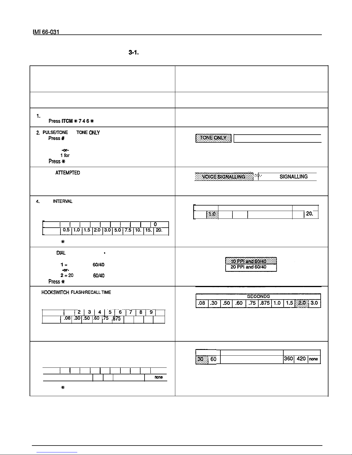
System Programming
Table
System COS Programming Reference
PROCEDURE
Note: Circle the record values at right
before performing the procedure given below.
BASE
LEVEL ENTRY
.
.
.
Press 0 for tone dialing
. Press
pulse/tone dialing
.
3. FIRST ATEMPTED INTERCOM SIGNALING MODE
Press Al3 for tone signalling.
. Press Al4 for voice signalling
. Press*
FOR PROGRAMMED PAUSE
. Press4
. Press one key
KEY 1 1 1 2 1 3 1 4 1 5 1 6 1 7 1 8
9
SEC.
RECORD
(Shading Denotes Default Value)
Note: Circle the desired value
for the system being programmed.
PULSE/TONE SWITCHABLE
I
. . . . . . . . .
. . .
. . ..: :..
TONE
SECONDS
0.5
1.5 1 2.0 1 3.0 5.0 7.5 10. 15.
. Press
5.
PULSE DlAL CHARACTERISTICS
PPI AND MAKE/BREAK
. Press5
. Press
10 PPI and
. Press
PPI and
.
6. HOOKSWITCH FIASHIRECALLTIME INTERVAL
. Press6
KEY
1 1
0
SEC.
1.0 1.5 2.0 3.0
. Press one key:
. Press*
7. HOLD RECALL TIME INTERVAL
. Press7
. Press one key:
KEY 1 1
2 1 3
4
5
6
7 1 8
9
0
SEC. 30 80 90 120 180 240 300 360 420
SECONDS
90 1120118012401300
. Press
3-13
Page 27

66-031 System Programming
TOLL RESTRICTION
.
Set system toll restriction requirements per instructions
given on Table 3-4
Record
toll restricbn data on table
9. SMDR DATA SPEED BAUD RATE
.
.
Press
baud
I
. Press1
.
Press
sec.
If a timeout occurs during the programming sequence, perform base level entry again
and proceed at any program step.
Page 28

66-031
System Programming
Table 3-2. Line COS Programmlng Reference
PROCEDURE
the information In the box at right before
performing the pfugram pfucadwes givan below
BASE LEVELENTRY
.
Press ITCM
746
PRNACY STATLJS
.
Press 6. All line6 private
.
Press keys for non-private.
.
.
. Press*
3. SELECT LINE FOR PROGRAMMING
.
Press 81-88 (model 0816X)
.
Press
(model 0616X)
4. SPECIFY LINE TYPE
.
= Auxiliary Line
5.
ASSIGN TOLL TABLES TO LINE
. Press
keys:
6. DIALING MODE OF LINE
.
Press 6 = pulse/tone
.
Press 7 = ton8
dialing
7. ABANDONED HOLD RECALLTIME
.
. Press
8. SELECT NEXT LINE FOR PROGRAMMING
.
Press Bl-B8 (model 0616X)
.
Press
(model 0616X)
9. END LINE
PROGRAMMING
. Press S MONITOR
NOTE:
a timeout occurs during the
RECORD
I
Check each line number block for rhe fine featwu that is
I
in the calling number and locaffon status.
NON-PRIVATENON-PRIVATE
RESTRICTIONRESTRICTION
CALLING NO.CALLING NO.
Change page
Page 29

System Programming
Table 3-3. Statlon COS Programming Reference
(Copy this sheet as required)
PROCEDURE
right before
RECORD
Enter lnfotmstion or circle desin?d
below before
2.
. Press RECALL
INTERCOM NUMBER
4.
PA PORT
(3
. . . .
..:..:c..
. . . . . . . . . . . .
. Press4
(0816X)
(4
. Press6
.
Press Bl-B6 (model D616X)
.
Press
(model 0816X)
Page 30

66-031
System Programming
Table 3-3, STATION COS PROGRAMMING REP ERENCE (Continued)
(Copy this sheet as required)
PROCEDURE
or enter the
at right
14. ALL
ZONE PAGING
.
Press #
to clear allcall.
.
Press keys:
= receive A. B, C, and all-call
.
Press keys:
= originate A. B. C and allcall
Dial
(0616X)
. Dial
used key and light
. Press*
17. PROGRAM NEXT
.
Repeat procedure from step 2
18. END
. Press MONITOR
a timeout occurs during the
sequence, perform base level entry again and
proceed at any progmm step.
3-17
Page 31

TABLE ENTRY PROCEDURE
Table
Toll RestrIctIon ProgrammIng Reference
3.
4.
5.
Determine the types of dialing restrictions which
must be imposed on the system.
this includes access codes which result in toll charges,
and certain local numbers as desired.
If the restricted dialing codes will be imposed consistently on most or all stations in the system, list
them on one or two tables. If wide variation in the
dialing restrictions is planned, spread the listing
out across several tables.
Strategically group the listings on the tables so
that a list of restrictions can be applied to a particular station or group of stations.
Designate each table as a DENY table or as an
ALLOW table. The numbers entered in a DENY
table are prevented from being dialed. ALLOW
tables take precedence over DENY tables.
Therefore, an entry in an allow table will provide
an expticit exception to an entry in a DENY table.
Note that the system always permits the dialing of
any number not explicitly denied.
Example A:
Provide a simple and broad toll
restriction format by creating a DENY table with
two entries: ENTRY (1) = 1 ENTRY (2)
0.
This format prevents all long distance and
operator calls.
Example B: Prevent the dialing of all numbers
within the (804) area code, while allowing the
dialing of one specific number within that area
code, by entering 1804 in a DENY table and
18049782200 in an ALLOW table.
Enter the # character in place of a particular digit
to condense a range of numbers into one entry.
The # character is a “match-anything” digit, and
can be included in an entry in either a DENY table
or an ALLOW table.
Example
A:
If
and 397 dialing
is to be prohibited, list one entry of 3#7 on a
DENY table to cover them all.
Example
B:
Since area codes typically have
a 1 or a 0 as a middle digit, prevent long dis-
tance calls to those area codes by entering
6. Since it is important that emergency numbers
never be restricted, always create an allow table
tables that have been created.
7. If the system is installed behind a PBX, include an
access code as part of every table entry.
8. Once these tables are completely filled out, enter
the restriction pfanning tables on the line, and station programming reference charts to record the
planned toll restrictions for the system.
PROGRAMMING PROCEDURE
1.
2.
3.
4.
5.
6.
Select toll restriction table
KEY
TABLE KEY
TABLE
Al
1
A5
5
A2 2 A6
6
A3 3 A7 7
A4 4 A8 8
Select table type
Select entry line
Dial entry number (16 digits max). Press
key to
enter “match anything” digit.
Repeat procedure for each table.
Press
MONITOR.
Chanae
3-18
Page 32

System Programming
TOLL RESTRICTION TABLE 1
TYPE: ALLOW DENY
ENTRY
ENTRY NUMBER (16 MAXIMUM)
TABLE ASSIGNMENT: LINES
STATIONS
I
TOLL RESTRICTION TABLE 2
TYPE: ALLOW DENY
ENTRY
ENTRY NUMBER (16 MAXIMUM)
I7
I I I I I I I I
I
TABLE ASSIGNMENT: LINES
STATIONS
TOLL RESTRICTION TABLE
TYPE: ALLOW DENY
ENTRY
ENTRY NUMBER (16 MAXIMUM)
TABLE ASSIGNMENT: UNES
TOLL RESTRICTION TABLE 3
TOLL
TABLE
TYPE: ALLOW DENY
ALLOW DENY
ENTRY ENTRY NUMBER (16
MAXIMUM)
ENTRY
ENTRY NUMBER (16
MAXIMUM)
,
5
I
I
I
I I
I
I I
I
I I I
TABLE ASSIGNMENT: LINES
STATIONS
I
TOLL RESTRICTION TABLE
4
TYPE: ALLOW
DENY
ENTRY ENTRY NUMBER
MAXIMUM)
TABLE ASSIGNMENT: LINES
STATIONS
I
TOLL RESTRICTION TABLE
8
NPE: ALLOW
ENTRY
DENY
ENTRY NUMBER (16 MAXIMUM)
TABLE ASSIGNMENT: LINES
STATIONS
I
3-19
Page 33

EXECUTECH MODELS 0616X, 0816X
CLASS OF SERVICE PROGRAMMING
NG KEY LAYOUT
-SYSTEM
ONLY SPECIFIES
LINES.
KM
TO
AS
EXT.
AT
m LINE
LINES
m
616X
616X KEY
USES
TO
TO
SEE
A
-AT ENTRY T
9
C.
IS
AS
NO
NO
NO
LINE
NO
LINE, NO
REMAIN INTACT.
TO
STATIONS. BY
RECEIVE.
Flgure
Programming Flow Dlagram
Page 34

CHAPTER 4
MAINTENANCE
Maintenance
TECHNICAL ASSISTANCE
AND REPAIR SERVICE
Technlcal Assistance
Should you expen’ence difficulty with installation,
checkout, or programming, and have made an attempt to isolate the problem using information
provided herein; or should you encounter problems at
a later date which cannot be resolved by referring to
this manual, call the Comdial Technical Service staff.
They can be reached between the hours of 8:00 AM
and 8:00 PM Eastern time, Monday through Friday.
Technical Services: l-800-366-8224
When calling for technical assistance, you should be
at the job site and you should have in your possession, as a minimum, an accurate volt-ohm meter and
a copy of this manual.
Repair Senrlce
If your KSU or an individual station needs repair, it
may be returned to Comdial. Comdial will, at their op
tion, either repair the defective equipment or replace
it with a remanufactured unit. This repair will be done
for a fixed charge. For information on this charge,
please call or write to the address given below.
Comdial
Charlottesville, VA 22906
Attention: Repair Department
Telephone: (804) 978-2400
When returning equipment for repair, pack it carefully
to prevent damage. Any damages during shipment
will be the responsibility of the purchaser. The equip-
ment should be shipped freight or postage prepaid.
The shipping address is:
Comdial
1180 Seminole Trail
Charlottesville, VA 22901
Attention: Repair Department
FUSE LOCATION
The KSU is protected against short circuit damage by
a fuse located in the primary of the AC transformer
winding. The fuse is a 1 amp,
SLO-BLO type
fuse. The fuse holder is located near the top of the
right side of the KSU cabinet. Always replace this
fuse with one of the same value
and type;
equipment damage could result.
FAILURE ISOLATlON
System Status indicator
The red LED located near the fuse holder is the sys-
tem status indicator. This indicator should turn on
steady when AC power is applied to the KSU. If the
indicator flashes after power up, it could be indicating
a processor failure. Unplug and reconnect the AC
power to the KSU and observe the LED indication. If
it still shows a flashing indication, refer to Figure 4-l.
Station Self Test
Exercise the station self test feature as follows:
1.
Disconnect the line cord at the station base.
NOTE:
ADJACENT ODD OR
EVEN STATION WILL BE DISABLED DURING
TIME THAT THE
CORD IS
BEING DISCONNECTED OR RECONNECTED.
2.
3.
Press and hold the MUTE key, and reconnect the
line cord to the station connector. The station will
automatically perform a
test routine. Release
the MUTE key as soon as the test begins. The
sequence of the test is as follows:
l
The tine select indicators will light in se-
quence from 1 to 8.
l
The intercom select indicator will light.
l
The speaker indicator will light.
l
All indicators will turn off in the same sequence.
l
Be sure that the
ringer volume control is set to the
medium or high volume setting.
Replace any station that does not pass the Self
test.
Test the DSS/BLF Console for proper lamp operation
per the following procedure.
1. Disconnect the console line cord plug from the
fne.
Change page
4-d
Page 35

66-031
Maintenance
Table
Station Pairing
2.
3.
Press and hold the station 10 select key while
reconnecting the line cord plug to the line.
IMPORTANTNOTE: THE COMPANION STATtON
WILL BE DISABLED DURING THE
THE CONSOLEIS BEING DISCONNECTED AND
RECONNECTED.
Release the station 10 select key, and note
that
the BLF indicators will each
turn
on in sequence
beginning with the station 10 indicator. The indicators will then turn off and the console will become operational.
Paired Stations
. .
ne
All stations are even/odd paired on the data lines as
shown in Table 4-l. Station 10 is paired with station
etc. If erratic light indications or ring signals occur
at a paired station, an open data pair at either station
may be the fault. A station with an open data line
may work properly on a short loop but fail on a long
loop. Test the station wiring per the checkout procedure given in Chapter 2.
. .
Overload Paultlg
All stations are paired as shown in Table 4-l for over-
load current protection. If a fault occurs which
causes more than 300 ma. of current to be drawn, the
paired stations are disabled by circuit action. Disconnect the disabled stations and reconnect them one at
a time
to
isolate the faulty one.
Failure Analysis
Figure 4-l details a failure analysis flow chart to assist a service technician in isolating a failure in a
defective system. One way to isolate a failure is to
substitute a known good assembly for a suspected
one, This is the recommended failure isolation
method to use with the system.
Connecting and disconnecting stations
to the
system
does not affect the stored station auto/speed dial
memory data. This data is stored in the KSU memory
and not at the individual stations. Replacing the
KSU, however, causes all stored memory to be lost.
This includes all memory dialing numbers as well as
all COS programming data.
4-2
Page 36

.
FAILURE
PERFORM
SELF TEST
YES
YES
INPUT FOR FAILED
UNUSED TELCORSX
JACK ON PSX
REPLACE KSU AND
PERFORM
Page 37

Index
66-031
.
INDEX
A
A-LEAD CONTROLDEVICE CONNECTlON
.....
2-3
AC POWER CONNECTION
...............
2-2
ACCESS DENIED
...................
3-7
ALL CALL PAGING
..................
3-7
AREA PAGING INTERFACE
UNE PORT
......
2-5
AREA PAGING INTERFACE
STATlON PA PORT . .
2-5
..............
3-4
BASE LEVEL PROGRAM ENTRY MODE
......
3-l
BUSY LAMP FIELD STATlONS
............
C
.....................
2-3
CALL ORIGINATION DENIED
............
3-7
CHECKOUT
......................
2-3
CLASS OF SERVICE DEFAULT
........... 3-l
COMMON AUDIBLE AND
.........
2-4
l-l
CONNECTION, PA
.................. 26
CONNECTION, A-LEAD CONTROL DEVICE
.....
2-3
CONNECTION. AC POWER
..............
2-2
CONNECTION. UNE
.................
2-2
CONNECTION, POWER FAILURE STATIONS
....
2-3
CONNECTION. DATA DEVICE
............
2-3
CONNECTION. DSSIBLF CONSOLE
.........
2-3
CONNECTIONS. STA-IION
..............
2-2
...................
3-3
D
DATA LINE PAIRING
.................
4-2
DATADEVICE CONNECTION
............ 23
DATASPEED BAUD RATE
..............
3-4
DEFAULT, CLASS OF SERVICE
...........
3-1
DEFAULTS, SYSTEM
.................
3-3
DEFAULTS, STATION
................. 38
DELAYED RINGING ASSIGNMENT
.........
3-7
WALL MOUNTING, STATlONS
...........
4-4
DIALING MODE
....................
3-3
DIRECT RINGING ASSIGNMENT
..........
.........
..............
........... 4-l
E
.................
F
FAILURE ISOLATION
.................
4-l
FAILURE ANALYSIS FLOW CHART
........
FAILURE ANALYSIS
..................
4-2
FCC RULES AND REGULATlONS
..........
l-l
...................
4-l
G
GENERAL CHECK
..................
2-3
GENERAL INFORMATlON, PROGRAMMlNG
.... 3-l
................
H
HELD CALL ABANDON TlME
.............
.................
3-3
.....
3-3
I
INDICATOR, SYSTEM STATUS
............ 4-l
..........
INSTALLATION
....................
2-l
INTERCOM SIGNALUNG MODE
...........
3-3
INTERCONNECTION. SYSTEM
............
2-7
INTRODUCTION
...................
l-l
K
KSU TO STATlON WlRlNG
..............
L
LINE COS PROGRAMMING REFERENCE
......
3-15
LINE CONNECTIONS
.................
2-2
......................
LINE DEFAULTS
...................
LINE COS PROGRAMMING PROCEDURE
.....
3-5
MAINTENANCE
.................... 4-l
MANUAL SCOPE
................... l-l
..............
2-2
..............
2-l
MOUNTING CONSIDERATIONS
...........
2-l
MUSIC ON HOLD
...................
2-5
N
NIGHTRINGING
...................
3-7
.
....
Page 38

66-031
Index
0
OVERLOAD PAIRING
..................
4-2
P
PA CONNECTlON
...................
.......................
PAIRED STATIONS
...................
4-2
PARTY LINES AND COIN LINES
........... l-l
POWER FAILURE STATION CONNECTION
.....
2-3
PRIME LINE/INTERCOM
...............
...............
PRINTOUT, SMDR AND COS
.............
3-8
PRIVACY RELEASE
..................
3-7
PRIVACY STATUS OF LINE
.............
3-5
PROGRAMMED PAUSE
...............
3-3
... 33
PROGRAMMING REFERENCE, LINE COS
.....
3-15
PROGRAMMING REFERENCE,
TOLL RESTRICTION
.................
3-18
PROGRAMMING. SYSTEM
..............
3-l
PROGRAMMING REFERENCE, STATION COS
...
3-16
PROGRAMMING KEYS
....
.............
3-l
PROGRAMMING REFERENCE,SYSTEM COS
...
3-13
PROGRAMMING, SYSTEM SPEED DlAL
...... 512
PROGRAMMING FLOW DIAGRAM
.........
3-21
PROGRAMMING PROCEDURE, STATION COS . . 3-6
PULSE DlAL CHARACTERISTICS
..........
3-3
RADIO FREQUENCY 1NTERFERENCE
....... l-2
RELATED PUBLlCATlONS
..............
1-l
REPAIRSERVICE
..................
4-1
REPAIR AUTHORlZATlON
..............
RESISTANCE CHECK
................
2-8
RINGER EQUIVALENCE NUMBER
.........
l-2
S
SELF TEST, DSS/BLF CONSOLE
.......... 4-l
SELF TEST, STATION-
................ 4-l
...................
SMDR AND COS PRINTOUT
.............
3-8
STATION
.................
STATION COS PROGRAMMING REFERENCE
...
STATION dONNECTlON
...............
2-2
STATION MESSAGE DETAIL
RECORD PRINTOUT FORMAT
............
3-9
STATlON DEFAULTS
.................
3-6
STATlON COS PROGRAMMING PROCEDURE . .
3-6
STATION WALL MOUNTING DETAILS
........
4-4
SYSTEM COS PROGRAMMING PROCEDURE
. 3-3
SYSTEM STATUS INDICATOR
............
4-l
SYSTEM PROGRAMMING
..............
3-l
SYSTEM COS PROGRAMMING REFERENCE
. 3-13
SYSTEM SPEED DIAL PROGRAMMING
.......
3-12
SYSTEM CLOCK INFORMATION
...........
3-11
SYSTEM INTERCONNECTION
............
2-7
SYSTEM WIRING
....................
2-2
SYSTEM GROUNDING
................
24
SYSTEM DEFAlJLlS
.................
T
TECHNICALASSISTANCE
.............. 4-l
TOLL RESTRICTION
PROGRAMMING REFERENCE
...........
3-18
TOLL RESTRICTION TABLES
............
TROUBLESHOOTING
................. l-l
TYPICAL COS PRINTOUT
..............
V
VOLTAGE CHECK
...................
2-8
W
WALL MOUNTING DETAILS, STATlON
........ 44
WIRING, KSU TO STATlON
..............
2-6
ZONE PAGING
....................
3-7
Page 39

Page 40

Page 41

Placing a call
.....................
Answering a call.
..................
Placing a call on hold.
.............
Placing intercom calls.
.............
Answering intercom calls.
..........
Transferring outside calls.
..........
Conference calls
..................
Redialing
.........................
Automatic dialing.
.................
Station speed dialing
..............
System speed dialing
..............
Line monitoring.
...................
Recall/Tap.
.......................
Area paging ......................
All call and zone paging
............
Direct station selection (DSS)
.......
Night transfer
.....................
Do not disturb.
....................
Pulse/tone switching
..............
l
Speakerphone operation
...........
12
BLF station operation
..............
12
I
Page 42

On hook
l Press line key. Listen for dial tone.
l Dial number.
l
handset, when party answers.
Hang up handset to end call.
Off hook
l Lift handset.
l Press line key. (This step is not
necessary if a line has been
assigned to you-a prime line.)
l Listen for dial tone.
l Dial number.
. Hang up handset to end call.
l Press line key. (This step is not
necessary if you have a prime line or
if your phone answers any ringing
line.)
l
Lift handset.
Manual hold
(Any station can retrieve held call.)
l
Press
. To return to call on hold, press
flashing line key.
Exclusive hold
(Only your station can retrieve held
call.)
l Press
twice.
Note:
Hold Recall-A call placed on hold will
Page 43

automatically ring at the station which placed it
on hold after a programmed period of time. If
the call is on exclusive hold, the call will revert
to manual hold after the initial period.
Voice signailing
l Lift handset.
l
Press
l Press a memory key (or dial
extension number). To call system
operator, dial 0.
l Voice announce.
Tone signalling
l
Press
l Press memory key (or dial extension
number).
l Press
again.
l When party answers, lift handset to
talk.
Note:
Some systems may be programmed to
tone signal as the first option. In that case the
first set of instructions applies to tone signaling,
the second to voice signaling.
To answer a voice-signalled intercom
call
l Speak toward the set.
l Lift handset if privacy desired.
To answer a tone-signalled intercom
call
l Lift handset to talk.
Page 44

Multiline conference
(2 external,
internal parties)
Note: Conference transmission levels are not
compensated and connections of parties must
be supervised by one inside party.
l
Establish first outside call and
press
l
Establish second outside call.
l Press and hold down line key for
second call.
If the line on which the call appears
is shared by you and the station to
receive the call
l Press(m). (Call is placed on hold
automatically.)
l Press a memory key (or dial
extension number).
l Voice announce the call and line
number.
l Hang up handset.
If station does not share line
appearance
l
(Call is placed on hold
automatically.)
. Press a memory key (or dial
extension number).
. Voice announce the call and ask
station to lift handset.
l Press
(Station immediately
has the call.)
To return to outside call
(busy or no answer)
l Press flashing line key.
Page 45
l Press line key for first call.
l Release both line keys. (Conference
is established.)
Add-on conference
external, 2 internal parties)
l Establish outside call.
l Press
(outside call placed on
hold).
l Press a memory key (or dial
extension number).
l Ask intercom party to lift his handset,
and to press and hold down the held
line key.
l Press and hold down the line key of
held outside call.
l Release line key when conference is
established.
Page 46
Last number redial
l
(If on line, listening to
dial tone, press shift key and then
Saved number redial
(saving a number just dialed)
l Press(m), during or after the
call.
l Press shift key and
Automatic redial
l When busy tone is heard, press
auto redial
key and hang up.
(Station will redial number once a
minute for
minutes.)
l To cancel, press auto redial key
again.
l When ringing tone is heard, lift
handset.
To program numbers
.
Listen for tone.
l
Tone will stop.
l Press desired memory key.
l If a specific line is to be used, press
the line key. (Otherwise, system will
pick prime line or last line used.)
l Dial number sequence to be stored.
(up to 15 digits)
l Press dial pad to store digits
I-O,
and
l Press
to store pause.
l Press
to store hookswitch
flash.
Page 47
l Repeat the last four steps for each
number to be stored.
l Press
to end programming.
To automatically dial numbers
l Press memory key.
l When party answers, lift handset.
To program numbers
l Follow same steps given for
Automatic Dialing using the dial
keys 1-O as memory locations,
To speed dial numbers
l Press desired dial key 1-O. (If on
line, listening to dial tone, press
shift key and then desired dial key
1-O.)
To program numbers
(Program from station
l
Listen for tone.
l Press(X). Tone will stop.
l
Press (SAVE).
l Press desired dial key 1-O.
l If a specific line is to be used, press
the line key. (Otherwise, system will
pick prime line or last line used.)
l Dial number sequence to be stored.
(up to 31 digits)
l Press dial pad to store digits l-0,
#and
l Press
to store pause.
l Press
to store hookswitch
flash.
Page 48
l Repeat the last four steps for each
number to be stored.
l Press
to end programming.
To dial numbers
then the dial key.
(If on line, listening to dial tone,
press shift key,
then the
desired dial key 1-O.)
r
To activate while on a call
l
Press
l Hang up handset.
Note: If a party places you on hold, you can
monitor until his return, then lift handset.
To cancel
l Lift handset to resume conversation
or press
to disconnect.
l If your system has been configured
for Tap, press
to generate a
timed “Flash” for accessing PBX,
and custom calling
services.
l If your system has been configured
for Recall, press
to discon-
nect, as if you had hung up, and
obtain a new dial tone for another
call.
Note:
System can be configured for Recall or
Tap, but not both.
Page 49

One-button access
(Paging unit connects to Key
Service Unit line port.)
l Press line
dedicated to paging.
l Lift handset. (Dial area code if
required.)
l Make announcement.
Two-button access
(Paging unit connects to Key
Service Unit station port.)
l
Press
l Lift handset.
l Press a memory key (or dial 2-digit
access code).
l Make announcement.
l Make announcement.
One-button intercom calling
(recommended for attendant
answering stations)
To program DSS numbers
l Press
Listen for tone.
l
Tone will stop.
l Press memory key (1-14).
Page 50

l
Press
l Dial station number.
l Repeat last four steps for all
stations.
l Press-.
Voice Signalling DSS
l Lift handset.
l Press memory key (l-l 4)
l Voice announce.
Note: If you are transferring a call, the
outside line is automatically placed on hold
when a memory key is pressed.
Tone Signalling DSS
l Press memory key
4).
l
Press
l When station answers, lift
handset.
To activate
(from station 10 only)
l
Listen for tone.
l Press
Tone will stop.
To cancel
l Repeat the two steps above.
To silence your ringer and appear
busy to intercom calls
l
Press
To cancel
l Press
again.
Page 51

To prevent other party from hearing
l Press and hold down(m).
l Release
to resume two-way
conversation.
If your telephone service is pulse
(rotary) and you must convert to
tone after selecting a line or while
dialing
l
(System will switch
back to pulse dialing when call is
terminated.)
Note:
switching can be
programmed
into memory keys by pressing
during number storage sequence.
Page 52

Placing a call
l Press line key.
Dial number or press memory key.
l When party answers, speak toward
the set.
Answering a call
l Press line key.
l Speak toward the set.
Ending a call
l
Press (~@WQ.
Switching from handset to
speakerphone
l Press
l Hang up handset.
Switching from speaker phone to
handset
l Lift handset.
l Lights
adjacent to memory
keys
indicate station statuses
(dark indicating idle, steady-on
indicating busy).
Note: On Model 824 system you must
program memory keys for DSS operation. (See
DSS programming.)
will then indicate
status of programmed stations.
 Loading...