

Page 1
DXP
Digital Communications System
Video Display Terminal
Programmmg Instructions
The procedures included in this
publication reflect software
releases through
9A.
Printed in U.S.A.
COMDIAL@
IMI66- 111.04
10195
Page 2

CERTIFIED
IS0 so01
Accredited by the Dutch Council
for Certification for certification
and registration activities.
Corndial’s Quality Management System Is
Certified To The IS0 9001 Standard.
ii
Page 3
VDT Programming Instructions
Table Of Contents
1
Understanding General Programming jnformation
2
Reviewing General Programming Considerations
3 Understanding Keyboard And Terminal Definitions
IMI664II
3.1
3.2 Reviewing the Control Key Definitions
3.3 Reviewing The Terminal Mode Definitions
4 Reviewing The Command Prompts And Error Reporting
4.1 Reviewing The Command Prompts
4.2 Reporting Errors
Performing The Terminal Emulation Programming
5
5.1 Reviewing The Programming Progression
Programming Sys tern Features
6
6.1
6.2
6.3
6.4
6.5
6.6
6.7
6.8
6.9
6.10
6.11
6.12
6.13
6.14
6.15
Reviewing The Keyboard Definitions
Default Functional Programming
VDT Display Configurations (Terminal Setup)
Messaging
Database Storage
Serial Port (Serial Data Port Parameters)
Subdued Off-Hook Voice Announce (SOHVA) Programming
Speed Dial Programming
System Clock (Time and Date)
System Timing
System Parameters
Paging Zones (Paging Programming)
Password Programming (Change Password)
Feature Renumbering
Programming The Tl Status Log Parameters
Major Alarm Alerting
Page 4
ZMZ66-111
7 Programming Station Feafures
8
VDT Programming Instructions
7.1 Programming Station Class Of Service Features
7.2 Programming Station Features
7.3 Square/Non-Square System (Button Mapping By Station)
7.4 Telephone Types (Phone Types)
7.5 Copy Model COS, Station, Button Map (Block Programming)
Programming Line Features
8.1
8.2
8.3
8.4
8.5
8.6
8.7
8.8
Line Programming
Line Group Programming
Copy Model Line (Block Programming, Line)
Direct Inward Dialing (DID) Support
Ground Start Line Support
Loop Start Line Support
Tie Line Support
Direct Inward System Access (DISA) Programming
9 Programming Intercom Numbers
9.1
Modifying Intercom Numbers
9.2 Adding Intercom Numbers
Removing Intercom Numbers
Renumbering Intercom Numbers
10 Pro
De f
9.3
9.4
ramming Call Costing and Station Message-
ail Accounting and Reporfs (SMDAISMDR Programming)
10.1 SMDA/SMDR Parameters
10.2 SMDA Reports
10.3
Account Codes (Forced, With Positive Verification)
10.4 Emergency Numbers
10.5 Authorization Code
I I
Programming Toll Resfricfion
iv Table Of Contents
11.1 Toll Restriction Example 1
11.2 Toll Restriction Example 2
11.3
11.4
1 P .5
1 P .6
Toll Restriction Flow Diagram
Restriction Level Programming
Toll Groups Programming
Restricted Numbers Programming
11.7 Exception Number Programming
Page 5
VDT Programming Instructions IMIW-111
12 Enabling Automatic Route Selection
12.1 Automatic Route Selection Diagram
12.2
12.3
ARS Enable
Line Groups for ARS
12.4 Route Tables (ARS
12.5 Costing Information (ARS)
12.6 Automatic Route Selection For Speed Dial Numbers
13 Selecting Sys tern Printouts (Printer Interface)
14 Programming For Peripheral Devices
14.1 Caller ID Programming
14.2 Tracker Paging System Programming
14.3
14.4
Digital Voice Announce Programming
PC Attendant Position Programming
14.5 Voice Mail Programming
14.6
Modem Setup
Page 6
This page remains blank intentionally.
vi Table Of Contents
Page 7
VDT Programming Instructions IMIhS-111
Understanding General
Programming Information
1
.i
It is best that you program the DXP digital communications system from a video display terminal
(VDT) that supports the ANSI standard escape sequences for cursor and video control. The VDT must
be a serial-data, RS-232 type, asynchronous device. The DXP system supports ANSI standard, ANSI
color, and WYSE 50 terminals with full screen editing of database information. Other types of
terminals use a line-by-line editing approach instead of a full screen editing approach and make
programming harder to do.
You can employ a personal computer (PC) if it will run a communications software program that allows
it to emulate a data terminal device (DTE equipment). Many communications software programs are
available for this purpose. One such program that works effectively is known as PROCOMM produced
by Datastorm Technologies; however, you can use any that match the following data communications
parameters:
0 full duplex,
0 XMODEM communication protocol (8 bit data required).
Regardless of the type of programming terminal that you employ, connect it to the common equipment
data port per the discussion found in IMI66-085, Installation Instructions For The DXP Digital
Communications System Main Cabinet Assembly.
You can program the DXP digital communications system remotely using the following equipment:
0 a VDT or a PC and appropriate software program,
l
a pair of data modems (one for your terminal and one for the remote site).
Refer to GCA40-07.5, Feature Applications For The DXP Digital Communications System, for complete
remote programming details.
It is possible for you to mismatch the data configurations of your programming terminal (VDT) with
those of the DXP and prevent data communications from occurring. You can reconfigure your VDT
until you match the data parameters of the DXP; however, the DXCPU-68K board provides a DIP
switch that changes the DXP data configuration to a fixed set of parameters. You can match your VDT
to this fixed set of parameters and eliminate any configuration guess work. When you set DIP switch 1
to its ON position, you fix the DXP serial data ports to the following parameters:
Parameter
Baud Rate In 9600
Baud Rate Out
Data Bits
Stop Bits
Parity Bits
Flow control None
Data Port A
9600 300
8
1
None
Data Port B
300
7
2
None
None
When you set the DIP switch to OFF, you can program the DXP data port configuration parameters
using the procedure detailed in Section 6.5, Serial Ports.
General Programming Information l-l
Page 8
This page remains blank intentionally.
l-2
General Programming Information
Page 9
VDT Programming Instructions
IlW66-d 11
Reviewing General
Programming Considerations
2
1
Since the programming procedure is menu driven, you should consider all of the following points.
0 The menu presents a list of selections for your consideration. Each selection differs in content and
requires a different response.
0 When you respond to each selection, it either causes the system to present a further breakdown of
selections or causes a particular programming action to take place.
0 Menu lines prompt you for the required response and, where appropriate, will repeat prompts to
allow programming of more than one device without you having to make another menu selection.
0 All of the menus operate in a similar manner. They differ in only the required response that you
must make.
l
Some menus contain more than one page. On these menus, you can press and hold the CONTROL
key while you type the N key to display the next page (or type P to display the previous page).
@ Each prompt requires a response followed by a Carriage Return (RETURN). A more common label
for this control on most PC keyboards is ENTER.
l
Most menu responses usually consists of a one-, two-, or three-digit number or a string of numbers
(or alpha-numeric characters when programming names and messages). Successive entries are
separated by a space or a comma (n n n or n,nn,nnn) while blocks of numbers are indicated by
hyphen (n-nnn).
l
Should programmers introduce a numbering conflict while renumbering a feature dialing code, the
system will prompt them to remove the conflict. They may have to renumber several features to
completely clear any conflicting numbers.
Programming Considerations 2-l
Page 10
IMl66-111
VDT Programming Instructions
This page remains blank intentionally.
2-2 Programming Considerations
Page 11
VDT Programming Instructions
Terminal Definrtions
/M&S-1 1 I
Understanding Keyboard And
3.1
The following list describes the functional keys on the keyboard.
l
Number keys: Use keys O-9 for selecting menu items, lines of data to edit, or
l
Alphabetic keys:
l
ESCAPE key:
o Punctuation and Symbol keys:
l
RETURN or ENTER key:
Reviewing The Keyboard Definitions
for editing numeric prompts.
Use keys A-Z and a-z for entering string information such as
names and messages. Always begin names of stations, lines, and
so forth with a letter or a space.
Either of these keys will return you to the previous command
prompt and cancel whatever input was in progress. This action
may or may not cause the previous screen to be redrawn
depending on the current mode. When you enter a change at
most of the programming menus, you must press the ESCAPE
key and type a y followed by the ENTER key to save the change.
Except for comma (which is a field delimiter), use the
punctuation and symbols on the keyboard just as you use the
alphabetic keys.
Use this key to terminate the response to a command prompt or
to end the editing of a data field. The system ignores a
RETURN without any preceding input except when you are
editing database information. During this operation, the
RETURN key moves the cursor to the next vertical editing
position.
l
SPACE BAR:
l
Tab Key:
@ Question mark (?):
The space bar steps through the choices for program selections
that provide multiple choices.
Use this key during table editing to position the cursor to the
next horizontal editing position.
This key will display any help available concerning the currently
displayed screen.
Keyboard and Terminal Definitions 3-l
Page 12
IMl66-111 VDT Programming Instructions
3.2 Reviewing The Control Key Definitions
The following list describes the control key functions. Unless otherwise noted, control keys are valid
input at any time during programming.
0 Control C (C for Cancel):
l
Control E (E for Edit or Erase):
0 Control I (I for Increment):
l
Control N (N for Next):
0 Control P (P for Previous):
l
Control R (R for Redraw):
0 Control X (X for exit):
This key will cancel the current mode or function and return you
to the last command prompt.
Use this key to edit a selected field or entry. On “smart”
terminals, most fields will be automatically cleared when the
first character is entered. Some fields allow the you to add to
the current entry. On these types of fields, Control E will clear
the entry and position the cursor at the beginning of the field.
You can also use this key to erase a field that has blanks for
valid input such as an autodial number.
Use this key during table editing to position the cursor to the
next horizontal editing position.
Use this key to switch to the next page of data for those database
items that fill more that one screen. There will always be an on
screen note when this key is valid.
This key is identical to the Control N key except that it displays
the previous page of information.
When you press this key the system will redraw the current
screen display. Usually, you use this key when the terminal
display is configured in brief mode.
Either of these keys will return you to the previous command
prompt and cancel whatever input was in progress. This action
may or may not cause the previous screen to be redrawn
depending on the current mode. When you enter a change at
most of the programming menus, you must press the ESCAPE
key and type a y followed by the ENTER key to save the change.
0 Control S (S for Stop):
l
Control T (T for Top):
Use this key to stop printouts.
Use this key to cancel whatever input was in progress and return
to the top level menu. The top level menu will always be
redrawn.
0 Control V:
Use this key to turn the entry field prompting on or off.
3.3 Reviewing The Terminal Mode Definitions
l
Control A:
o Control D:
0 Control W:
3-2 Keyboard and Terminal Definitions
Use this key to cause the system to send and receive data to an
ANSI style terminal.
Use this key to cause the system to send and receive data to a
“dumb” terminal.
Use this key to cause the system to send and receive data to a
Wyse 50 compatible terminal.
Page 13
Reviewing The Command
Prompts and Error Reporting
4.1 Reviewina The Command Prompts
There are four different types of command prompts.
0 Menu Selection Prompt: Use this prompt to make a menu selection. The system requires a numeric
input and displays the valid range of numbers in the prompt that corresponds to the number of menu
items displayed.
0 Edit Line Prompt: Use this prompt on database editing screens to get to the desired line number to
be edited. The system requires a numeric input and displays the valid range of numbers in the
prompt that corresponds to the number of menu items displayed. Entering a RETURN (ENTER) at
this prompt will automatically select the first item.
l
Station, Line or Class Of Service Prompt: Use this prompt to get to the particular item or items
that are to be edited. This prompt is waiting for numbers, a range of numbers, or names. You may
specify a single item or multiple items separated by commas. Select a range of items by entering
two numbers separated by a dash. The prompt shows the valid range of numbers but the system will
accept names. The system accepts an item as a name if the first character is not a number. The
system displays the database information of each item one at a time for viewing or editing. When
you use the ESCAPE key to exit the database information screen, the system displays the next item
in the list. When you use CONTROL C to exit the screen, all list processing stops and the prompt
display returns. When you use CONTROL T to exit the screen, the system stops all list processing
and displays the top level menu.
l
Multiple Choice Question Prompt: This type of prompt asks a specific question concerning the
current screen or function and shows the valid responses. Enter these responses as a single character
followed by a RETURN (ENTER).
4.2
Pressing unexpected keys (such as letters when only numbers are allowed) or entering an out-of-range
value at a prompt causes the keyboard alarm to sound. The system responds to other types of input
errors by displaying an error message on the screen as soon as it detects the error. If the system detects
a value-out-of-range error, and if the valid range is not currently shown in the display, the error message
includes the valid range of values for reference.
There is one circumstance for which the system does not report an entry error and this is when you are
listing items at a station, line or COS prompt. In this case, the system processes valid items in the list up
to the first invalid item that it encounters. It does not report the encountered invalid item as an error.
Reporting Errors
Command Prompts and Error Reports 41
Page 14
IMl66- 111
VDT Programming Instructions
This page remains blank intentionally.
4-2 Command Prompts and Error Reports
Page 15
Performing The VDT Programming
5
-I
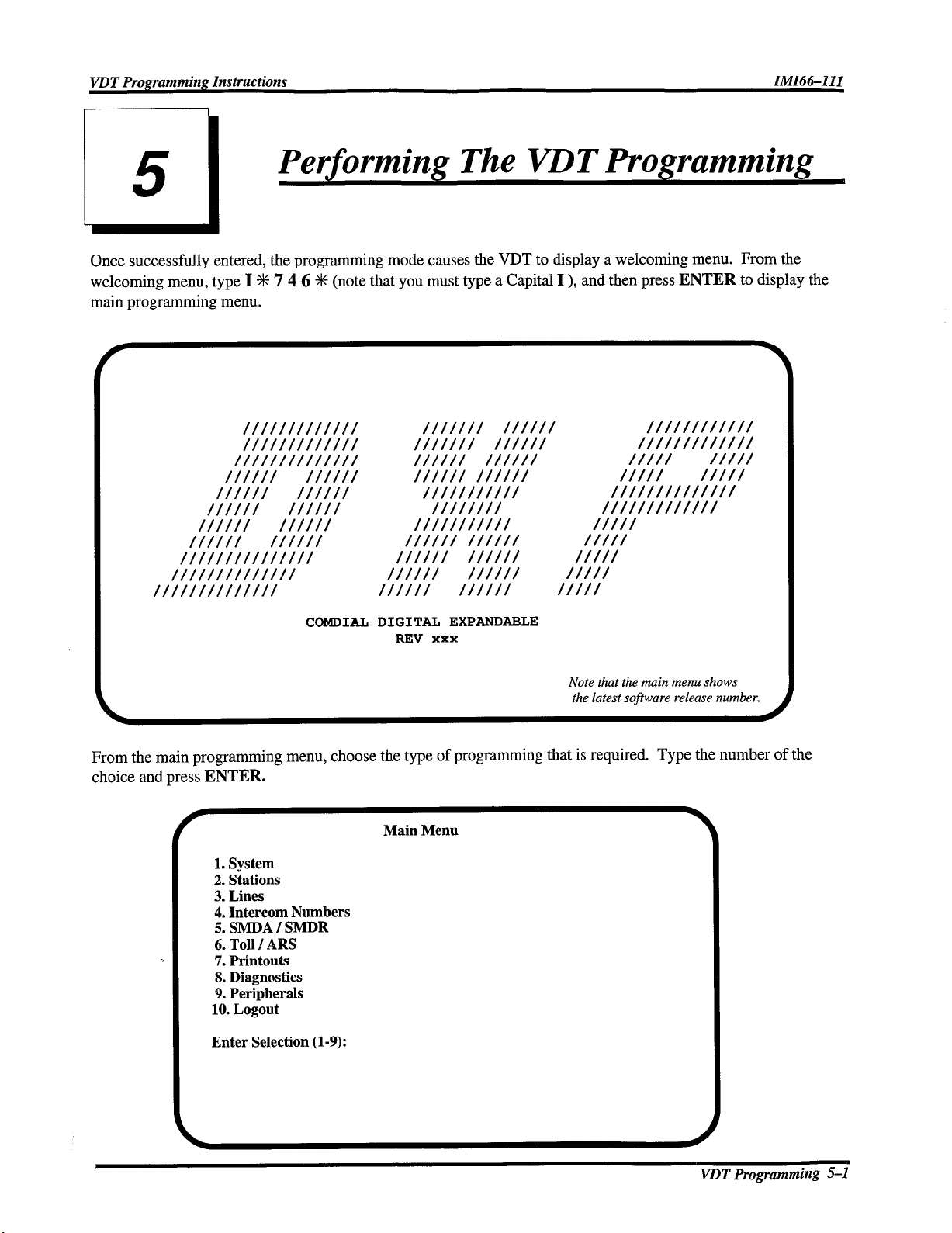
Once successfully entered, the programming mode causes the VDT to display a welcoming menu. From the
welcoming menu, type I S 7 4 6 S (note that you must type a Capital I ), and then press ENTER to display the
main programming menu.
COMDIAL DIGITAL EXPANDABLE
REV xxx
Note that the main menu shows
the latest sojiware release number.
From the main programming menu, choose the type of programming that is required.
choice and press ENTER.
Main Menu
1. System
2. Stations
3. Lines
4. Intercom Numbers
5. SMDA I SMDR
6. Toll / ARS
7. Printouts
8. Diagnostics
9. Peripherals
10. Logout
Enter Selection (l-9):
Type the number of the
VDT
Programming S-1
Page 16
5.1
Reviewing The Programming Progression
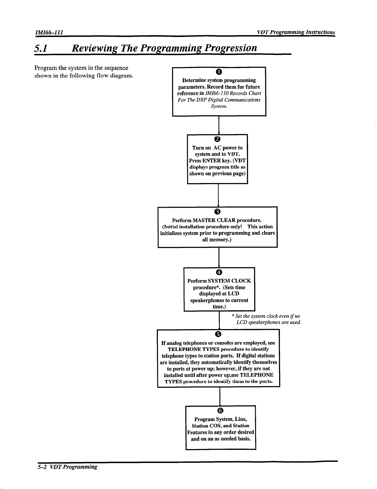
Program the system in the sequence
shown in the following flow diagram.
Determine system programming
parameters. Record them for future
reference in IMI66-110 Records Chart
For The DXP Digital Communications
System.
Turn on AC power to
system and to YDT.
Press ENTER key. (VD’I
displays program title as
shown on previous page]
Perform MASTER CLEAR procedure.
(Initial installation procedure only! This action
initializes system prior to programming and clears
all memory.)
Perform SYSTEM CLOCK
procedure*. (Sets time
displayed at LCD
speakerphones to current
time.)
* Set the system clock even
LCD speakerphones are used.
I
If analog telephones or consoles are employed, use
TELEPHONE TYPES procedure to identify
telephone types to station ports. If digital stations
are installed, they automatically identify themselves
to ports at power up; however, if they are not
installed until after power up,use TELEPHONE
TYPES procedure to identify them to the ports.
1
I
Program System, Line,
Station COS, and Station
Features in any order desired
and on an as needed basis.
0
1
if no
5-2 VDT Programming
Page 17
VDT Programming Instructions
Ml66-1
I 1
Programming
.
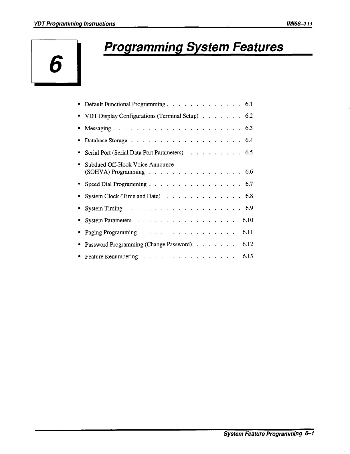
Default Functional Programming ............. 6.1
.
VDTDisplay Configurations (Terminal Setup) ....... 6.2
.
Messaging
.
Database Storage ................... 6.4
.
Serial Port (Serial Data Port Parameters) ......... 6.5
.
Subdued Off-Hook Voice Announce
(SOHVA) Programming ................ 6.6
.
Speed Dial Programming ................ 6.7
.
System Clock (Time and Date) ............. 6.8
.
System Timing
......................
....................
System Features
6.3
6.9
.
System Parameters ................. 6.10
.
Paging Programming ................ 6.11
.
Password Programming (Change Password) ....... 6.12
.
Feature Renumbering ................
6.13
System Feature Programming 6-l
Page 18
IM166111
VDT Programming Instructions
6.1
Default Functional Programming
6.1.1 Master Clear
Description:
The master clear feature in an on-line procedure that returns the entire system to the default
operating parameters, clears all stored speed dial numbers, and clears any other custom
programming as well. Master clear is not part of the off-line PCMMI programming procedure.
The system takes 15 to 20 seconds to exercise a master clear command depending upon the
system size.
You can take one of three different master clear options.
With master clear mode 1 option, the system assumes a set of parameters that reflect a key
system arrangement. This means that multiline telephones, except stations 101 and 102, receive
direct line appearances in their button maps but have no group intercoms assigned to their hunt
lists. Stations 101 and 102 have four group intercom numbers assigned to their hunt lists and are
button mapped accordingly.
With master clear mode 2 option, the system assumes a set of parameters that reflect a hybrid,
or PBX-like, system arrangement. This means that multiline telephones have no direct line
appearances in their button maps; however, they do have two unique group intercoms assigned
to their button maps and to their hunt lists.
With master clear mode 3 option, the system assumes a set of parameters, that does not map any
station buttons, assigns no group intercom access or personal intercom numbers to the stations,
and disables both zone and all-call paging features.
Programming:
You can only exercise the master clear when you enter the programming session with
the installer password;
the same as the installer password thus giving master clear privileges to the
administrator as well. Refer to Section 6.12, Password Programming to customize the
passwords.
1. Press CONTROL T for main menu.
2. From main menu, select system and press ENTER.
3. From system menu, select defaults and press ENTER.
4. Select master clear and press ENTER.
5. Type y or n (yes or no) to confirm master clear; press ENTER.
6. Select system default mode (1 = mode 1,2 = mode 2,3 = mode 3) and press ENTER.
however, in a defaulted system, the administrator password is
6-2 System Feature Programming
Page 19

VDT Programming Instructions
Central Processor Unit Switched Master Clear
Description: When following the installation procedures for software replacement as described in publication
IMI89-095,
Card and SojIware Upgrade Card,
and replace the memory card. If you do not master clear the system, it is possible the DXP will
not perform properly with the new memory card. The DXCPU-68K board provides a method
for the master clear to occur automatically at the initial power up after you have changed or
upgraded the software card. When you perform an upgrade, you must execute the following
sequence of events exactly as they are stated here:
Programming: 1. Save the system data base. This step is critical. Refer to Section 6.4, Database Storage
for programming details.
2. Turn off the AC power to the DXP and replace the memory card on the DXCPU-68K board.
Refer to IMI89-095 for mechanical details.
3. Set DIP switch 8 to its ON position. This step enables the DXP to perform the
master clear and is a required step; otherwise, the software upgrade will not occur.
4. Install the DXCPU-68K board and new software card in the DXP, and turn on the
AC power. The DXP automatically executes a master clear operation.
5. After system powers up, set DIP switch 8 to its OFF position, and restore the data base
using the Section 6.4 procedure.
NOTE: The system performs the automatic master clear once following the initial power up after you
Installation Instructions DXP Digital Communications System Expanded Memory
you are told to save the data base, master clear the system,
have up-graded the software. It will not pe$orm an automatic master clear operation again after
subsequent power ups.
System Feature Programming 6-3
Page 20
IMl66-111
VDT Programming Instructions
6.1.2 System Default
Description: The system default sets the system configuration features to the default operating parameters.
When the system default is performed, certain programmed data, such as custom LCD messages
and system speed dial numbers, are lost.
Programming;
1. Press CONTROL T for main menu.
2. From main menu, select system and press ENTER.
3. From system menu, select defaults and press ENTER.
4. From defaults menu, select system and press ENTER.
5. Type y to confirm default or n to deny.
6.1.3 Class Of Service Default
Description: There are 32 station class of service (COS) feature sets or grouping of features. Each set can
have differently configured features. This default programming returns one or all station COS
sets to the default configured parameters.
Programming: 1. Press CONTROL T for main menu.
2. From the main menu, select system and press ENTER.
3. From the system menu, select defaults and press ENTER.
4. From the defaults menu, select station COS and press ENTER.
5. Type l-32 to enter class of service to be defaulted. Enter the
numbers for the COS sets to be defaulted (n,n,nn) or enter a range of numbers (n-nn).
6.1.4 Station Default
Description: Each station can have individually configured operating features. The station default sets the
configuration of these features to the default parameters. Personal speed dial numbers and
autodial numbers are cleared with the station default action.
Programming: 1. Press CONTROL T for main menu.
2. From main menu, select system and press ENTER.
3. From system menu, select defaults and press ENTER.
4. From defaults menu, select stations and press ENTER.
5. Type intercom number or station name.
6-4 System Feature Programming
Page 21
VDT Programming Instructions
fMl66-I 11
6.1.5
Description:
Programming:
Button Map Default
Every programmable button at each telephone connected to the system provides line selection,
direct station selection, or other functions. Programming action for a particular station assigns a
function to each button. Unique button function assignment, known as button mapping, at each
station is possible. This default erases all unique button function assignments.
1. Press CONTROL T for main menu.
2. From main menu, select system and press ENTER.
3. From system menu, select defaults and press ENTER.
4. From defaults menu, select button maps and press ENTER.
5. Type intercom number or station name.
6.1.6 Line Default
Description:
Programming:
Each line can have individually configured operating conditions. The line default sets these
conditions to the default parameters.
1. Press CONTROL T for main menu.
2. From main menu, select system and press ENTER.
3. From system menu, select defaults and press ENTER.
4. From defaults menu, select lines and press ENTER.
5. Type line port number (l- 128) or name.
6. Enter the numbers for the lines to be defaulted (n,n,nn) or enter a range of numbers (n-nnn).
6.1.7 Tables Default
Description:
Programming:
Various system-wide operating features depend upon tables of information to control their
parameters. These tables are programmable to let the features match a broad range of site
requirements. This table default procedure resets the following programmable tables to the
default conditions: SOHVA tables, toll restriction tables, ARS route tables, modify digits tables,
and account code verify tables.
Remember, the system erases all programmed entries when you take this
defaulting action.
1. Press CONTROL T for main menu.
2. From main menu, select system and press ENTER.
3. From system menu, select defaults and press ENTER.
4. From defaults menu, select tables and press ENTER.
5. Type y to confirm default or n to deny.
piliEzq
Sys tern Feature Programming 6-5
Page 22
6.1.8 DID Translation Table, Default
Description: If you have programmed translation tables for DID use (Section 8.4.4, DID Translation Table
Programming), you can clear them with this procedure.
Programming;
1. Press CONTROL T for main menu.
2. From main menu, select system and press ENTER.
3. From system menu, select defaults and press ENTER.
4. From defaults menu, select DID translation table and press ENTER.
5. Type DID table number (l-4) and press ENTER.
6. Repeat step 5 until finished.
7.
Press ESCAPE to end.
6.1.9 Clear Svstem Status Loa
Description: If you have enabled system status reporting (Section 6.10.6, System Status Reporting) at a
station, you can turn off its status light by using this procedure. Use the Section 13 procedure to
view the status report before turning off the light at the status reporting station.
Programming;
1. Press CONTROL T for main menu.
2. From main menu, select system and press ENTER.
3. From system menu, select defaults and press ENTER.
4. From defaults menu, select clear system status log and press ENTER.
5.
Press ESCAPE to end.
6-6 Sys tern Feature Programming
Page 23
VDT Programming Instructions
6.1.10 Voice Prompts/Programming Default
IMl66-IIf
Description:
Programming: 1. Press CONTROL T for main menu.
6.2
Description: You must match the system to the type of VDT that you use to program it.
Programming:
If your system includes a Digital Voice Announcer (DVA) you can use the following procedure
to clear voice messages, the translation digits, and the voice analysis report of all existing
information. Refer to Section 14.3.3, Programming for DVA Operation, for the programming
discussion about these features.
2. From main menu, select system and press ENTER.
3. From system menu, select defaults and press ENTER.
4. From defaults menu, select voice prompts/programming and press ENTER.
5. Type letter code for DVA feature to be defaulted.
6. Press ESCAPE to end.
Terminal Setup (VDT Display Configurations)
1. Press CONTROL T for main menu.
2. From main menu, select system and press ENTER.
3. From system menu, select terminal setup and press ENTER.
4. From terminal setup menu, type selection (l-4) for terminal choice.
5. Press SPACE bar to change or ENTER to maintain.
6. When finished, press ESCAPE twice.
7. Type y to accept changes, n to reject them, or r to resume editing and press ENTER.
System Feature Programming 6-7
Page 24

6.3 Messaging
6.3. I LCD Messaging
Description:
Programming: To enable feature for class of service,
This procedure enables a class of service messaging feature. It allows station users to set a
message at their stations that will be displayed on calling LCD speakerphones. You can use the
second part of this procedure to program the actual LCD messages. Alternately, The attendant
can program the LCD messages using procedures found in the attendant guide.
Also refer to Section
1. Press CONTROL T for main menu.
2. From main menu, select stations and press ENTER.
3. From stations menu, select COS programming and press ENTER.
4. Type class of service number (l-32) and press ENTER.
5. From COS programming menu Type item number for feature and press ENTER.
6. Press SPACE bar for feature setting.
7. When finished, press ESCAPE twice.
8. Type y to accept changes, n to reject them, or r to resume editing and press ENTER.
9. Repeat steps 4-8 for each COS or press ESCAPE to end.
To program LCD Messages,
1. Press CONTROL T for main menu.
2. From main menu, select system and press ENTER.
3. From system menu, type item number for feature and press ENTER.
4. From LCD messages menu, type selection (l-10) and press ENTER.
5. Type message and press ENTER. Message can be 16 characters long.
6. Repeat steps 4 and 5 for all messages. Press CONTROL N for more LCD message lines.
7. When finished, press ESCAPE twice.
8. Type y to accept changes, n to reject them, or r to resume editing and press ENTER.
63.2, Message Deposit.
Operation:
6-6 System Feature Programming
Turn message on: press INTERCOM, dial S 02, then dial message code ( 01 through 30) #.
Turn Message off: press INTERCOM, dial # 02.
Page 25
VDT Programming Instructions
/M/66-1 11
6.3.2 Message Deposit (Response Messaging)
Description: This procedure enables a class of service messaging feature that allows station users to call an
LCD speakerphone and arrange for a message to be left on its display. The message is for the
called party to read if she or he is unable to answer the caller.
Messaging,
can use the procedure detailed in Section
Station,
themselves if they need the button.
for details about programming the LCD messages that can be deposited. Also, you
7.3, SquareBVonsquare System-Button Mapping By
to assign a Response Message button to the telephone; however, users can do this for
Refer to Section 6.3.1, ECD
Programming:
1. Press CONTROL T for main menu.
2. From main menu, select stations and press ENTER.
3. From stations menu, select COS programming and press ENTER.
4. Type class of service number (l-32) and press ENTER.
5. From COS programming menu, type item number for feature and press ENTER.
7. When finished, press ESCAPE twice.
8. Type y to accept changes, n to reject them, or r to resume editing and press ENTER.
9. Repeat steps 4-8 for each COS or press ESCAPE to end.
6.3.3 Message Waiting (Message Wait Originate)
Desctiption: When you enable this feature, a station user can dial a feature code to control the message
waiting light at another station.
Programming: 1. Press CONTROL T for main menu.
2. From main menu, select stations and press ENTER.
3. From stations menu, select COS programming and press ENTER.
4. Type class of service number (l-32) and press ENTER.
5. From COS programming menu, type item number for feature and press ENTER.
6. Press SPACE bar for feature setting.
7. When finished, press ESCAPE twice.
8. Type y to accept changes, n to reject them, or r to resume editing and press ENTER.
9. Repeat steps 4-8 for each COS or press ESCAPE to end.
Operation: Turn message waiting light on: press INTERCOM, dial X 3.
Turn message waiting light off: press INTERCOM, dial # 3.
System Feature Programming 6-9
Page 26
IMl6&111
VDT Programming Instructions
6.4 Database Storage
6.4.1 Save/Restore Database
Description: This feature will save a database externally from the DXP and restore it after you have turned
the DXP off and upgraded the operating system software. Also, you can use this feature anytime
to back up the stored programming as a security measure. Employ a personal computer with an
XMODEM communications program to store the database on a magnetic diskette and reload it
from the diskette after software upgrades. The saved and reloaded database includes the
following data: system information, station parameters, line parameters, toll restriction and
automatic route selection parameters, and system speed dial numbers but it does not include the
SMDA/SMDR records. If you need these SMDABMDR records, you must make a printout of
them before you perform the database storage. This is necessary because this save/restore
feature does not record the stored records and they will be lost. Use the Section 13, Selecting
System Printouts,
software upgrade considerations.
NOTE: This programming procedure details steps that one follows when using the communications
software program known as PROCOMM (produced by Datastonn Technologies). If you are using
a different communications software, your steps may be different.
During programming, the system stores feature data at several places in its database. To ensure
that a database save procedure includes all of a feature’s stored data, the system saves the entire
database whenever you perform the save/restore database programming procedure.
procedure for this purpose. Also refer to Section 6.4.2,
Soj?ware Upgrade,
for
Programming: To save the database,
1. Press CONTROL T for main menu.
2. From main menu, select system and press ENTER.
3. From system menu, select save/restore database menu and press ENTER.
4. Type item number for save database and press ENTER.
5. Press page-down button.
6. Type prompted number to choose XMODEM protocol.
7. Type name of file where database is to be stored, and press ENTER.
Database save is automatic.
8. To quit, press ESCAPE.
To restore the database,
1. Press CONTROL T for main menu.
2. From main menu, select system and press ENTER.
3. From system menu, select save/restore database menu and press ENTER.
4. Type item number for restore database and press ENTER,
5. Press page-up button.
6. Type prompted number to choose XMODEM protocol.
7. Type name of file where database is stored and press ENTER.
Database restore is automatic.
8. To quit, press ESCAPE.
6-70 System Feature Programming
Page 27

VDT Programming Instructions
1111116611 d
6.4.2
Description:
Software Upgrade
This feature will save a database internally within the memory of the DXP and restore that
database after you have turned the DXP off and upgraded the operating system software.
Saving the database in this manner eliminates the need for a personal computer with an
XMODEM communications program to translate the database between software upgrades. The
saved and reloaded database includes all of the following data: system information, station
parameters, line parameters, toll restriction and automatic route selection parameters, and
system speed dial numbers but it does not include the SMDABMDR records. If you need these
SMDABMDR records, you must make a printout of them before you can perform the database
storage. This is necessary because this save/restore feature overwrites the current stored records
and they will be lost. Use the Section 6.13,
For this procedure to work properly, the system must include the expanded memory
card (DXRAM-EXP68K). If the system has the standard memory card
(DXRAM-STD68K), you should use the procedures detailed in Sections 6.1.1, Master
Clear, and 6.4.7, Save/Restore Database.
Programming: 1. Press CONTROL T for main menu.
2. From main menu, select system and press ENTER.
3. From system menu, select default and press ENTER.
4. From default menu, select onboard software upgrade and press ENTER.
5. Type y for yes or n for no to respond to prompt concerning SMDABMDR records.
6. After the system saves the database, turn off the AC power to the system,
upgrade the operating software, and turn the AC power back on. The system will
automatically reload the saved database into the upgraded operating software and log
out of the programming mode.
NOTE: The system will take an additional two to three minutes to power up after it receives ACpower
because of the time requiredfor the database restore processing.
Feature Renumbering,
procedure for this purpose.
System Feature Programming 6-1 I
Page 28

IMl66-111 VDT Programming hstructions
6.5
Description:
Programming: 1. Press CONTROL T for main menu.
Serial Ports (Serial Data Port Parameters)
The DXP provides two main serial data ports on the CPU board. In addition, it provides four
auxiliary serial ports on each DXOPT-COM communications card that your installer adds to
each DXAUX auxiliary circuit board. Since a DXAUX board accepts two DXOPT-COM cards
and the system accepts two DXAUX boards, the DXP can provide a maximum of 16 auxiliary
serial data ports. Coupled with the two main serial data ports, the system provides a total of 18
serial data ports. Every serial data port provides an RS-232 interface that you can use for such
things as VDT and data printer connection. The system recognizes the serial data ports by
unique number identifiers. The main serial data ports are 1 and 2, and the serial data ports on the
first DXAUX board are 3-6 (upper slot) and 7-10 (lower slot). The serial data ports on the
second DXAUX board are 11-14 (upper slot) and 15-18 (lower slot). The port numbering of
the auxiliary serial data ports are fixed. This means that if the system provides only one
DXOPT-COM located in the lower slot on the first DXAUX board, the auxiliary serial data
ports are 7-10.
Use this procedure to set the data communications parameters of the serial data ports. The serial
data parameters that you set using this procedure remain in effect until you reprogram them.
The settings will not change even if you perform a master clear of the system unless you use the
switched master clear method detailed in Section 6.1, Central Processor Unit Switched Muster
Clear. With that procedure, the system also defaults its serial data ports.
2. From main menu, select system and press ENTER.
3. From system menu, select serial ports and press ENTER.
4. From serial ports menu, type item number for main port or for auxiliary port
and press ENTER.
5. From serial port type menu, select the serial port number and press ENTER.
6. Press SPACE bar for feature setting
7. Press TAB for next parameter.
8. Repeat steps 6 and 7 for all parameters.
9. Press ENTER to accept settings.
10. When finished, press ESCAPE twice.
11. Type y to accept changes, n to reject them, or r to resume editing and press ENTER.
12. Press ESCAPE to end.
6-72 System feature Programming
Page 29
VDT Programming Instructions
IMl66-111
6.6
Subdued Off-Hook Voice Announce
(SOHVA) Programming
6.6. I Busy On SOHVA
Description: At default, the system returns a ring back tone to users who make SOHVA calls to busy
stations; however, this procedure allows you to arrange for telephone users to receive a busy
signal instead of the ring back tone. This feature lets non-LCD telephone users know that a
called station is busy.
Programmhg:
1.
Press CONTROL T for main menu.
2.
From main menu, select stations and press ENTER.
3.
From stations menu, select station programming and press ENTER.
4.
Type personal intercom number or previously assigned name and press ENTER.
5.
From station programming menu, type item number for feature and press ENTER.
6.
Press SPACE BAR for feature setting and press ENTER.
7.
When finished, press ESCAPE twice.
8.
Type y to accept changes, n to reject them, or r to resume editing and press ENTER.
Repeat steps 4-8 for each station or press ESCAPE to end.
9.
6.6.2 SOHVA Beeps (SOHVA Tone Bursts)
Description: You can choose the number of tone bursts that each telephone user hears preceding a SOHVA
message to be from one to six.
Programming: 1. Press CONTROL T for main menu.
2. From main menu, select station and press ENTER.
3. From stations menu, select station programming and press ENTER.
4. Type personal intercom number or previously assigned name for station and press ENTER.
5. From station programming menu, type item number for feature and press ENTER.
6. Type choice (l-6) and press ENTER.
7. Press ESCAPE twice.
8. Type y to accept changes, n to reject them, or r to resume editing and press ENTER.
9. Repeat steps 4-9 for each station or press ESCAPE to end.
System Feature Programming 6-13
Page 30
IMl66-111
VDT Programming Instructions
6.6.3
Description:
Programming:
SOHVA Grams
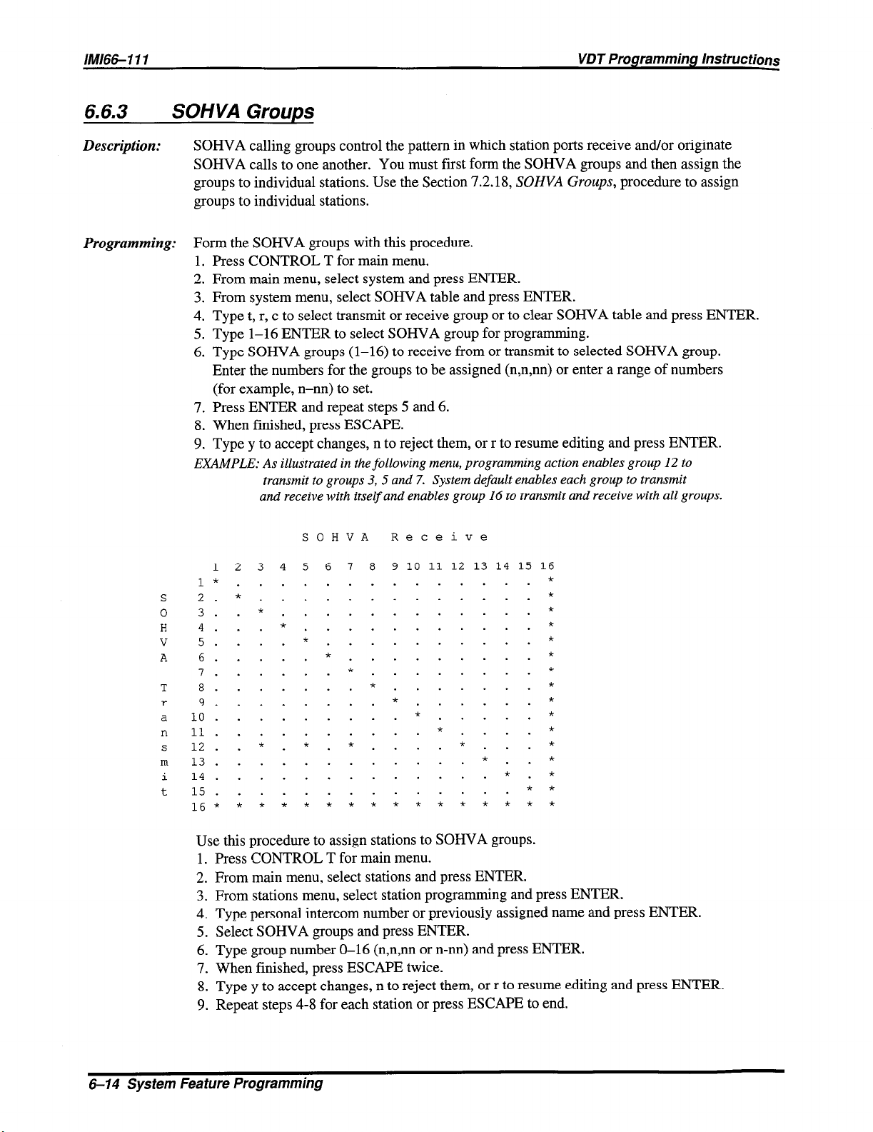
SOHVA calling groups control the pattern in which station ports receive and/or originate
SOHVA calls to one another. You must first form the SOHVA groups and then assign the
groups to individual stations. Use the Section 7.2.18,
groups to individual stations.
Form the SOHVA groups with this procedure.
1. Press CONTROL T for main menu.
2. From main menu, select system and press ENTER.
3. From system menu, select SOHVA table and press ENTER.
4. Type t, r, c to select transmit or receive group or to clear SOHVA table and press ENTER.
5. Type 1-16 ENTER to select SOHVA group for programming.
6. Type SOHVA groups (1-16) to receive from or transmit to selected SOHVA group.
Enter the numbers for the groups to be assigned (n,n,nn) or enter a range of numbers
(for example, n-nn) to set.
7. Press ENTER and repeat steps 5 and 6.
8. When finished, press ESCAPE.
9. Type y to accept changes, n to reject them, or r to resume editing and press ENTER.
EXAMPLE: As illustrated in the following menu, programming action enables group 12 to
transmit to groups 3, 5 and 7. System default enables each group to transmit
and receive with itself and enables group 16 to transmit and receive with all groups.
SOHVA Groups,
procedure to assign
SOHVA Receive
12 3 4 5 61 a 9 10 11 12 13 14 15 16
1*..............*
2.*.............*
3..*............*
4...*...........*
5....*..........*
6.....*.........*
7......*........*
a.......*.......*
9........*......*
lo......... * . . . . . *
11..........* . . - .*
12.. *. *. * . . . . * . . . *
13............ * . . *
14.............* .*
15..............**
16*
k * 3~ ,c * 3~ * ?T * * * * * * *
Use this procedure to assign stations to SOHVA groups.
1. Press CONTROL T for main menu.
2. From main menu, select stations and press ENTER.
3. From stations menu, select station programming and press ENTER.
4. Type personal intercom number or previously assigned name and press ENTER.
5. Select SOHVA groups and press ENTER.
6. Type group number O-16 (n,n,nn or n-nn) and press ENTER.
7. When finished, press ESCAPE twice.
8. Type y to accept changes, n to reject them, or r to resume editing and press ENTER.
9. Repeat steps 4-8 for each station or press ESCAPE to end.
6-14 System Feature Programming
Page 31

6.7 Speed Dial Programming
6.7.1
D lescription: During speed dialing, it is sometimes necessary to have the system delay the sending of digits to
Programming: 1. Press CONTROL T for main menu.
Pause Time
give host system switching equipment time to prepare to receive them. A pause, stored in the
speed dial number, provides this delay. This programming procedure determines the duration of
the pause. The person who stores the speed dial number must press the telephone’s HOLD
button at the point in the number digit sequence where he or she needs the pause (for example,
9-pause-18049782200).
2. From main menu, select system and press ENTER.
3. From system menu, type item number for feature and press ENTER
4. From system timing menu, type appropriate line number and press ENTER
5. Press SPACE bar for feature setting and press ENTER to accept setting.
6. When finished, press ESCAPE twice.
7. Type y to accept changes, n to reject them, or r to resume editing and press ENTER.
6.7.2 Speed Dial Groups
Description:
The system provides 500 system speed dial numbers. These numbers are divided into 50 groups
with 10 numbers available in each group. Assign none, one, or a range of groups (n-nn) to each
station class of service. Also refer to Section
6.7.4, System Speed Dial.
Programming: 1. Press CONTROL T for main menu.
2. From main menu, select stations and press ENTER.
3. From stations menu, select COS progrannning and press ENTER.
4. Type class of service number (l-32) and press ENTER.
5. From COS programming menu, type item number for feature and press ENTER.
6. Type desired value (O-50) and press ENTER.
7. When finished, press ESCAPE twice.
8. Type y to accept changes, n to reject them, or r to resume editing and press ENTER.
9. Repeat steps 4-8 for each COS or press ESCAPE to end.
System Feature
Programming 5-15
Page 32

IMl66-111
VDT Programming Instructions
6.7.3 Speed Dial Sets
Description: A speed dial set is a group of 10 speed dial locations. The system allocates three speed dial sets
to each telephone as a default but you can allocate up to 10 sets to a telephone if you wish.
When a DSSIBLF console is operated as a companion to a telephone, you can allocate speed
dial sets at the companion telephone that the system will then share with the console. The
system reserves one speed dial set for the telephone’s dial pad buttons O-9.
Programming: 1. Press CONTROL T for main menu.
2. From main menu, select stations and press ENTER.
3. From stations menu, select station programming and press ENTER.
4. Type personal intercom number or previously assigned name and press ENTER.
5. From station programming menu, type item number for feature and press ENTER.
6. Type desired value for feature and press ENTER.
7. When finished, press ESCAPE twice.
8. Type y to accept changes, n to reject them, or r to resume editing and press ENTER.
9. Repeat steps 4-8 for each station or press ESCAPE to end.
6.7.4
Description: Use this programrning feature to provide a list of 500 speed dial numbers to all stations in the
Programming:
System Speed Dial
system. Choose the prime line/last line used or designate the line or line group that the system
will automatically select for speed dialing. Store up to 32 digits including l-9, S, #, Hookflash
signalling, and pauses. Also refer to Sections
Route Selection For Speed Dial Numbers.
Beginning with software release 8.B, you can alternately choose the intercom to be
automatically selected for speed dialing. This enhancement allows you to store intercom
selection along with feature codes as speed dial numbers for true one-button access to features
(for example; store INTERCOM ++l 1 and INTERCOM #l at two locations for system wide
availability to music on and music off). This enhancement will not accept SKIS or S#746S as
programming entries and it ignores any entered pauses or hookflashes.
1. Press CONTROL T for main menu.
2. From main menu, select system and press ENTER.
3. From system menu, select speed dials and press ENTER.
4. From speed dial menu, type item number to edit or press ENTER for line 1.
NOTE: Pressing ENTER causes the system to accept the entry and move the cursor vertically one location
downward. Pressing TAB causes the system to accept the entry and move the cursor horizontally
one location to the right. Pressing and holding CONTROL while typing an E erases a number.
5. Press TAB to set cursor to preset column.
6. Press SPACE bar to choose intercom, prime/last (line), line, line group, or ARS.
7. Enter 1-128 for line port, 1-16 for line group, or 1-128 for ARS line to store
as prefix to speed dial number.
8. Press TAB for number entry column.
9. Type speed dial number (up to 32 digits of: O-9, %, #, P = pause, F = hookflash)
and press ENTER.
10. Repeat steps 4-9 for all speed dial numbers
11. When finished, press ESCAPE twice.
12. Type y to accept changes, n to reject them, or r to resume editing and press ENTER.
6.7.2, Speed Dial Groups,
and 12.6,
Automatic
Bperation: While on hook, dial % 100 through +K 599.
6-l 6 Sys tern Feature Programming
Page 33

VDT Programming Instructions
6.8 System Clock (Time and Date)
IM66-1 I I
Description:
Programming:
The system clock provides time and date information for display on LCD speakerphones and for
SMDRBMDA timing and reporting. You must set the correct time and date to allow the system
to operate properly.
1. Press CONTROL T for main menu.
2. From main menu, select system and press ENTER.
3. From system menu, type item number for feature and press ENTER.
4. Type time in 24 hour format (hh:mm) using leading
zeros for entries less than 10 and then press ENTER.
5. Type date (mm-dd-yy) using leading zeros for entries less than 10 and press ENTER.
6.9 Sys tern Timing
6.9. I
Description:
A call that is left in a park orbit longer than the length of time that you program with this feature will
automatically return to a hold recall condition at the parking station. Also refer to Section 7.1.6,
Programming:
Call Park Recall
Call Park.
1. Press CONTROL T for main menu.
2. From main menu, select system and press ENTER.
3. From system menu, select timing and press ENTER
4. From system timing menu, type item number for feature and press ENTER.
5. Press SPACE bar for feature setting and press ENTER to accept setting.
6. When finished, press ESCAPE twice.
7. Type y to accept changes, n to reject them, or r to resume editing and press ENTER.
6.9.2 Page Recall
Description:
Programming:
This timing feature determines the amount of time that a Tracker page remains in a Tracker
page orbit before recalling to the paging station. Refer to Section 14.2,
Programming
1. Press CONTROL T for main menu.
2. Form main menu, select system and press ENTER.
3. From system menu, select system timing and press ENTER.
4. From the system timing menu, type item number for feature and press ENTER.
5. Press SPACE bar for feature setting and press ENTER to accept setting.
6. When finished, press ESCAPE twice.
7. Type y to accept changes, n to reject them, or r to resume editing and press ENTER.
Tracker Paging System
for complete Tracker programming information.
System Feature Programming 6-l 7
Page 34

IMl66-111
6.9.3 Carno-On Tone
VDT Programming instructions
Description:
Programming:
Use this procedure to set the duration of the call waiting tone that the system sends to a busy
station. Also refer to Section 7.1.8, Cull Waiting.
1. Press CONTROL T for main menu.
2. Form main menu, select system and press ENTER.
3. From system menu, select system timing and press ENTER.
4. From the system timing menu, type item number for feature and press ENTER.
5. Press SPACE bar for feature setting and press ENTER to accept setting.
6. When finished, press ESCAPE twice.
7. Type y to accept changes, n to reject them, or r to resume editing and press ENTER.
6.9.4 DTMF Extended Dialing (Tone Length)
Description:
Use this programming feature to set the length of the DTMF tones. The system generates
DTMF tones of extended length when users take their telephones off-hook and then wait until
after the system sounds the extended dialing tone burst before they engage automatic dialing
(for example, press speed dial buttons or saved number redial button) at their stations. Also, if
analog telephone users take their telephones off-hook and then wait to begin manually dialing
until after the system sounds the extended dialing tone burst, the system will extend the length
of the manually dialed DTMF tones. After setting this extended DTMF tone length, you must
enable the feature’s use at each station where it is needed (Section 7.2.31, Extended DTMF
Dialing).
Programming:
1. Press CONTROL T for main menu.
2. From the main menu, select system and press ENTER.
3. From the system menu, select timing and press ENTER.
4. From the system timing menu, type item number for feature and press ENTER.
5. Press SPACE bar for feature setting and press ENTER to accept setting.
6. When finished, press ESCAPE twice.
7. Type y to accept changes, n to reject them, or r to resume editing and press ENTER.
6-18 System Feature Programming
Page 35

6.9.5 Timed Recall (Held And Transferred Calls)
Attendant Hold Recall
Description: After a call has been on hold at an attendant station for a programmed length of time it recalls to
the attendant station. Use this procedure to set the length of the recall time for a held call at an
attendant station.
Programming: I. Press CONTROL T for main menu.
2. From main menu, select system and press ENTER.
3. From system menu, select timing and press ENTER
4. From system timing menu, type item number for feature and press ENTER.
5. Press SPACE bar for feature setting and press ENTER to accept setting.
6. When finished, press ESCAPE twice.
7. Type y to accept changes, n to reject them, or r to resume editing and press ENTER.
Hold Recall
Description: After a call has been on hold at a station for a programmed length of time it recalls to the station
that placed it on hold. Use this procedure to set the length of the recall time for a held call.
Programming: 1. Press CONTROL T for main menu.
2. From main menu, select system and press ENTER.
3. From system menu, select timing and press ENTER
4. From system timing menu, type item number for feature and press ENTER.
5. Press SPACE bar for feature setting and press ENTER to accept setting.
6. When finished, press ESCAPE twice.
7. Type y to accept changes, n to reject them, or r to resume editing and press ENTER.
Station Transfer Recall
Description:
Programming:
After a transferred call has been waiting at a station for a programmed length of time it recalls
to the station that transferred it. Use this procedure to set the recall time for a transferred call.
1. Press CONTROL T for main menu.
2. From main menu, select system and press ENTER.
3. From system menu, select timing and press ENTER
4. From system timing menu, type item number for feature and press ENTER.
5. Press SPACE bar for feature setting and press ENTER to accept setting.
6. When finished, press ESCAPE twice.
7. Type y to accept changes, n to reject them, or r to resume editing and press ENTER.
Sys tern Feature Programming
6- 19
Page 36

IMl66- 111
6.9.6 Paging Access
VDT Programming Instructions
Description: If you have enabled paging transmit capability (see Section 6.11.3, Paging
station, it has access to external paging equipment. With this procedure, you can set the
maximum length of time that the station can stay connected to the equipment.
Programming: 1. Press CONTROL T for main menu.
2. From main menu, select system and press ENTER.
3. From system menu, select timing and press ENTER.
4. From system timing menu, type item number for feature and press ENTER.
5. Press SPACE bar for feature setting and press ENTER to accept setting.
6. When finished, press ESCAPE twice.
7. Type y to accept changes, n to reject them, or r to resume editing and press ENTER.
6.9.7
Description:
Pause Time
During speed dialing, it is sometimes necessary to have the system delay the sending of digits to
give host system switching equipment time to prepare to receive them. A pause, stored in the
speed dial number, provides this delay. This programming procedure determines the duration of
the pause. The person who stores the speed dial number must press the telephone’s HOLD
button at the point in the number digit sequence where he or she needs the pause (for example,
9-pause-18049782200). Also see Section
6.7, Speed Dial Programming.
Transmit)
at a
Programming:
1. Press CONTROL T for main menu.
2. From main menu, select system and press ENTER.
3. From system menu, type item number for feature and press ENTER
4. From system timing menu, type appropriate line number and press ENTER
5. Press SPACE bar for feature setting and press ENTER to accept setting.
6. When finished, press ESCAPE twice.
7. Type y to accept changes, n to reject them, or r to resume editing and press ENTER..
6.9.8 Recall/Flash
Description: A station can generate either a line disconnect signal (recall) or a host system feature access
signal (flash) when its user presses the telephone’s TAP button. Use this procedure to arrange
for either the recall or the flash signal.
Programming: 1. Press CONTROL T for main menu.
2. From main menu, select system and press ENTER.
3. From system menu, select timing and press ENTER.
4. From timing menu, type item number for feature and press ENTER.
5. Press SPACE bar for feature setting and press ENTER.
6. When finished, press ESCAPE twice.
7. Type y to accept changes, n to reject them, or r to resume editing and press ENTER.
6-20 System Feature Programming
Page 37

VDT Programming Instructions
IMl66111
6.9.9 Periodic Tone Time
Description: After you enable the periodic warning tones that remind users to keep conversations short on
certain outside lines (Section 7.1.3 1, Periodic Line Tone), use this procedure to set how often
that you wish the periodic warning tones to occur
Programming:
1. Press CONTROL T for main menu.
2. From main menu, select systems and press ENTER.
3. From system menu, select timing and press ENTER.
4. From system timing menu, type item number for feature and press ENTER.
5. Press SPACE bar for feature setting and press ENTER to accept setting.
6. When finished, press ESCAPE twice.
7. Type y to accept changes, n to reject them, or r to resume editing and press ENTER.
6.9. IO Maximum Call Duration (Time)
Description: After you enable the maximum call duration feature (Section 7.1.32, Maximum Call Duration),
use this procedure to set the cut off time.
Programming: 1. Press CONTROL T for main menu.
2. From main menu, select systems and press ENTER.
3. From system menu, select timing and press ENTER.
4. From system timing menu, type item number for feature and press ENTER.
5. Press SPACE bar for feature setting and press ENTER to accept setting.
6. When finished, press ESCAPE twice.
7. Type y to accept changes, n to reject them, or r to resume editing and press ENTER.
6.9.11 In ternal In terdigit Dialing
Description:
Programming: 1. Press CONTROL T for main menu.
A timer starts running with the dialing of each digit during intercom number dialing. It also
starts running whenever the user accesses the intercom number path and does not dial any
digits. When the timer times out, the system returns the station to an idle state. Use this
procedure to set the intercom dialing time-out period for the entire system.
2. From main menu, select system and press ENTER.
3. From system menu, select timing and press ENTER.
4. From system timing menu, type item number for feature and press ENTER.
5. Press SPACE bar for time and press ENTER.
6. When finished, press ESCAPE twice.
7. Type y to accept changes, n to reject them, or r to resume editing.
8. Press ENTER to end.
Sys tern Fea tore Programming 6-21
Page 38

6.9.12
Description: After you have given a station the ability to set up an unsupervised conference between two
Programming: 1. Press CONTROL T for main menu.
Line-To-Line Connect Duration
lines (Section 7.1.36, Line-To-Line Transfer), you should use this procedure to set the
maximum amount of time that an unsupervised conference can continue between two lines.
When the time out occurs, the system recalls the station from where the user enabled the
unsupervised conference.
2. From main menu, select system and press ENTER.
3. From system menu, select timing and press ENTER.
4. From timing menu, type item number for feature and press ENTER.
5. Press SPACE bar for feature setting and press ENTER.
7. When finished, press ESCAPE twice.
8. Type y to accept changes, n to reject them, or r to resume editing and press ENTER.
6.9.13 Camp-On/Automatic Call Back Ring
Description:
Programming: 1. Press CONTROL T for main menu.
After you use Section 7.1.8, Call Waiting Tone, to enable a call waiting tone, use this procedure
to set the duration of the camp-on/automatic ringback ring that the system sounds when it
returns a camp-on call to the original station..
2. Form main menu, select system and press ENTER.
3. From system menu, select system timing and press ENTER.
4. From the system timing menu, type item number for feature and press ENTER.
5. Press SPACE bar for time and press ENTER to accept setting.
6. When finished, press ESCAPE twice.
7. Type y to accept changes, n to reject them, or r to resume editing and press ENTER.
6.9.14 Out Dial Delav Time
Description:
Programming:
The system will wait for a programmed length of time before sending automatically dialed
numbers over an outside line. This delay gives the host system time to return dial tone before
the system begins dialing the number. Different host systems require different periods of time
between when a line is picked up and when dial tone is returned. Use this procedure to match
this system to your host system.
1. Press CONTROL T for main menu.
2. From main menu, select system and press ENTER.
3. From system menu, select timing and press ENTER.
4. From system timing menu, type item number for feature and press ENTER.
5. Press SPACE bar for feature setting and press ENTER.
6. When finished, press ESCAPE twice.
7. Type y to accept changes, n to reject them, or r to resume editing and press ENTER.
6-22 System Feature Programming
Page 39

VDT Programming Instructions
6.9.15 Authorization Code Time-out
IM166-111
Description:
Programming: 1. Press CONTROL T for main menu.
6.9.16
Description: Use this procedure to set the number of times that the system sends a ring signal to an
Programming:
Use the Section 10.5, Authorization Code, procedure to enable authorization codes. Once a user
uses an authorization code feature to access his or her telephone features, they remain in effect
until any idle time at the telephone exceeds the authorization code time-out period that you
program with the following programming steps.
2. From main menu, select system and press ENTER.
3. From system menu, select timing and press ENTER.
4. From timing menu, type item number for feature and press ENTER.
5. Press SPACE bar for feature setting and press ENTER.
7. When finished, press ESCAPE twice.
8. Type y to accept changes, n to reject them, or r to resume editing and press ENTER.
/ST Ring Time-out
industry-standard telephone on a system-wide basis. Although the ringing stops at the
industry-standard telephone when the time-out occurs, the system continues to present the call
at the telephone for answering until the caller abandons it. See Section 7.2.35,
Industry-Standard Telephone Support, for other IST programming requirements.
1. Press CONTROL T for main menu.
2. From main menu, select system and press ENTER.
3. From system menu, select timing and press ENTER.
4. From timing menu, type item number for feature and press ENTER.
5. Press SPACE bar for time and press ENTER to accept setting.
6. When finished, press ESCAPE twice.
7. Type y to accept changes, n to reject them, or r to resume editing and press ENTER.
6.9.17
Description: You can program the amount of time that the system waits to receive a DTMF tone from an
Programming:
/ST DTMF Receiver Time-out
industry-standard telephone, after the user has lifted the telephone’s handset and before he or
she has pressed a dial pad digit, on a system-wide basis. The system disconnects the telephone
after this time-out occurs. If this happens, the user must hang up the handset and lift it again to
re-establish the dial tone. See Section 7.2.35, Industry-Standard Telephone Support, for other
IST programming requirements.
1. Press CONTROL T for main menu.
2. From main menu, select system and press ENTER.
3. From system menu, select timing and press ENTER.
4. From system timing menu, type item number for feature and press ENTER.
5. Press SPACE bar for time and press ENTER to accept setting.
6. When finished, press ESCAPE twice.
7. Type y to accept changes, n to reject them, or r to resume editing and press ENTER.
System Feature Programming 6-23
Page 40

IMl66- 111 VDT Programming hstructions
6.9.18 /ST Flash Time
Description:
Programming:
You can program the timed length of the signal that results when a user of an industry-standard
telephone presses and releases the telephone hookswitch (or presses the TAP button if available
on his or her telephone) on a system-wide basis. Often, a signal with a short time length
(typically 500-750 ms) serves to alert the system to receive a feature code (flash) while a signal
with a long time length (typically 1 S-2.0 set) serves to disconnect the line and re-establish dial
tone (recall). The value that you set with this procedure is the maximum value for recognizing a
flash from an industry-standard telephone. Beginning with software release 6.A, you can also
set the minimum value for recognizing a flash from an industry-standard telephone. See Section
7.2.35, Industry-Standard Telephone Support, for other IST programming requirements.
1. Press CONTROL T for main menu.
2. From main menu, select system and press ENTER.
3. From system menu, select timing and press ENTER.
4. From timing menu, type item number for minimum flash time and press ENTER.
5. Press SPACE bar for minimum time and press ENTER to accept setting.
6. Press ENTER to select maximum flash time line item.
7. Press SPACE bar for maximum time and press ENTER to accept setting.
8. Type y to accept changes, n to reject them, or r to resume editing and press ENTER.
6.9.19 Voice Mail DTMF Tone
Description: The system provides a means by which you can set the length of the DTMF tones that it
generates when a user dials a number from his or her telephone. Since the voice mail system
may require a different DTMF tone length than that which you have provided for the
telephones, the system provides a means for you to set a separate DTMF tone length for voice
mail station ports. It defaults the length to 80 msec, but you can program other lengths as
needed. Refer to Section 15, Voice Mail Programming, for other voice mail programming
requirements.
Programming:
1. Press CONTROL T for main menu.
2. From main menu, select system and press ENTER.
3. From system menu, select timing and press ENTER.
4. From system timing menu, type item number for feature and press ENTER.
5. Press SPACE bar for time and press ENTER to accept setting.
6. When finished, press ESCAPE twice.
7. Type y to accept changes, n to reject them, or r to resume editing and press ENTER.
6-24 System Feature Programming
Page 41

6.9.20 Pulse Dial Interdigit Time
Description: You can set the interdigit time between dial pulses when the system pulse-dials a number over a
line. The DXP defaults this time to 200 msec. and provides a range of timing values between
100 msec. and one sec. that you can set in 100 msec. increments. Refer to Section
8.1.8, Dialing
Mode, to enable pulse dialing.
Programming: 1. Press CONTROL T for main menu,
2. From main menu, select system and press ENTER.
3. From the system menu, select timing and press ENTER,
4. From timing menu type item number for feature and press ENTER,
5. Press SPACE bar to select desired time and press ENTER to select setting.
6.
Press ESCAPE twice,
7. Type y to accept changes, n to reject them, or r to resume editing and press ENTER.
6.9.21 Pulse Dial Make/Pulse Dial Break (Pulse Dial Ratio)
Description: Use this procedure to set the make/break ratio for rotary dial signalling to match rotary dial line
requirements. You can set the line make/break ratio for rotary dial (pulse dial) signalling in a
more flexible manner to match many different rotary dial line requirements. You can set the
make time and the break time independently in one msec. increments to any time from one to 99
msec. Refer to Section
8.1.8, Dialing Mode,
to enable pulse dialing.
Programming: 1.
Press CONTROL T for main menu,
2.
From main menu, select system and press ENTER.
From system menu, select timing and press ENTER,
3.
From timing menu, type item number for line pulse make and press ENTER.
4.
5.
Type desired time (l-99) and press ENTER,
6.
From timing menu, type item number for line pulse break and press ENTER,
7.
Type desired time (l-99) and press ENTER,
8.
Press ESCAPE twice,
9.
Type y to accept changes, n to reject them, or r to resume editing and press ENTER,
6.9.22 Dialing Complete
Description: With systems operating with the E-l Digital Carrier Line Board feature, you must use this
timing feature to set the maximum amount of time that a user can wait between digits when he
or she is dialing a number. In the E-l operating environment, the central office system will not
wait indefinitely for the caller to completely dial a number. Refer to the central office
specifications for timing requirements.
Programming: 1. Press CONTROL T for main menu,
2. From main menu, select system and press ENTER.
3. From the system menu, select timing and press ENTER,
4. From system timing menu type item number for feature and press ENTER,
5. Press SPACE bar to select desired time and press ENTER to select setting.
6.
Press ESCAPE twice,
7. Type y to accept changes, n to reject them, or r to resume editing and press ENTER.
System Feature Programming 5-25
Page 42

6.9.23 Periodic Conference Tone
Description:
Programming: 1. Press CONTROL T for main menu,
6.9.24
Description: The executive advisory tone allows you to configure the system to provide an audible tone
The conference advisory tone feature allows you to configure the system to provide an audible
tone whenever more than two parties are connected in a conference call. You can enable this
feature with a station class of service programming action (Section 7.1.47, Conference Advisory
Tone) as either a one time tone or as a periodic reoccurring tone. If you choose a reoccurring
tone, you must use the procedure herein to select the time interval between the reoccurring
tones. Also refer to Section 6.10.19, Locution Code.
2. From main menu, select system and press ENTER.
3. From the system menu, select timing and press ENTER,
4. From timing menu type item number for periodic conference tone and press ENTER,
5. Press SPACE bar to select desired time and press ENTER to select setting.
6. Press ESCAPE twice,
7. Type y to accept changes, n to reject them, or r to resume editing and press ENTER.
Periodic Executive Override Tone
whenever a system user activates the executive override feature. You can enable this feature
with a station class of service programming action (Section 7.1.48, Executive Override Advisory
Tone) as either a one time tone or as a periodic reoccurring tone. If you choose a reoccurring
tone, you must use the procedure herein to select the time interval between the reoccurring
tones. Also refer to Section 6.10.19, Location Code, and Section 7.1.14, Executive Override
Programming.
Programming:
1. Press CONTROL T for main menu,
2. From main menu, select system and press ENTER.
3. From the system menu, select timing and press ENTER,
4. From timing menu type item number for periodic conference tone and press ENTER,
5. Press SPACE bar to select desired time and press ENTER to select setting.
6. Press ESCAPE twice,
7. Type y to accept changes, n to reject them, or r to resume editing and press ENTER.
6-26 System Feature Programming
Page 43

VDT Programming Instructions
IMl66-111
6.10
System Parameters
6.10.1 Synchronized Ringing
Description.= The system can provide an audible distinction between internal and external call ringing when
needed. Enable or disable that feature with this programming procedure. This feature does not
apply to direct inward dial lines (Section 8.4, Direct Inward Dialing Support) and E&M lines
(Section 8.7, Tie Line Support).
Programming:
1. Press CONTROL T for main menu.
2. From main menu, select system and press ENTER.
3. From system menu, select system parameters and press ENTER.
4. From system parameters menu, select synchronized ringing.
5. Press SPACE bar for feature setting.
6. When finished, press ESCAPE twice.
7. Type y to accept changes, n to reject them, or r to resume editing and press ENTER.
8. Press ESCAPE to end.
6.10.2 Automatic Attendant Immediate Transfer
Description: You should choose this automatic attendant immediate transfer mode for voice mail transfers.
It allows the system to transfer a call as soon as it answers. However, if you turn on the voice
mail screen and confirm options (see the voice mail programming manual for details), do not
turn on this immediate transfer mode. Immediate transfer is a system-wide parameter and
affects all telephones in the system.
Programming: 1. Press CONTROL T for main menu.
2. From main menu, select system and press ENTER.
3. From system menu, select system parameters and press ENTER.
4. From system parameters menu, type item number for feature and press ENTER.
5. Press SPACE bar for feature setting and press ENTER.
6. When finished, press ESCAPE twice.
7. Type y to accept changes, n to reject them, or r to resume editing and press ENTER.
System Feature Programming tL27
Page 44

/M/66-1
11
6.10.3 Automatic Route Selection (A RS Enable)
VDT Programming Instructions
Description:
You
can enable or disable automatic route selection on a system-wide basis. A defaulted
system has ARS disabled. Refer to Section 12, Enabling Automatic Route Selection, for other
ARS programming details.
Programming: 1. Press CONTROL T for main menu.
2. From main menu, select system and press ENTER.
3. From the system menu, select system parameters and press ENTER.
4. From the system parameters menu, select ARS feature and press ENTER.
5. Press SPACE BAR to toggle between enable and disable.
6. Press ESCAPE twice.
7. Type y to accept changes, n to reject them, or r to resume editing and press ENTER to end.
6.10.4 ARS (Automatic Route Selection) Dial Tone
Description: You can select one of three ARS dial tones that you hear whenever you enter the ARS access
code.
l
Dial Tone l-steady intercom dial tone (dual tones of 480 Hz + 620 Hz),
0 Dial Tone 2-same as dial tone 1 only preceded by three short tones (200 ms on,
200 ms off)
l
Dial Tone 3-steady simulated central office ring back tone (dual tones of 440 Hz +
480 Hz).
Programming:
1. Press CONTROL T for main menu.
2. From main menu, select system and press ENTER.
3. From system menu, select system parameters and press ENTER.
4. Select ARS dial tone from the system parameters and press ENTER.
5. Press SPACE bar to toggle between dial tone 1, dial tone 2, and dial tone 3.
6. When finished, press ENTER.
7. Press ESCAPE twice to end.
6-28 System Feature Programming
Page 45

VDT Programming Instructions IMl66-111
6.10.5 Toll / A RS Dialing Pause
Description: To create toll restriction parameters for the system, program restricted numbers as entries in the
toll restriction table using programming details provided in Section 11.6, Restricted Number
Programming. From that discussion, learn about entering a pause as part of the restricted
number’s digit string. Use the following programming procedure to enable the system to accept
that pause entry at the end of a restricted number’s digit string.
Programming:
6.10.6
Description: Use this procedure to enable system status reporting. If you enable status reporting, the system
Programming:
1. Press CONTROL T for main menu.
2. From main menu, select system and press ENTER.
3. From system menu, select system parameters and press ENTER.
4. From system parameters menu, select toll/ARS dialing pause and press ENTER.
5. Press SPACE bar for feature setting.
6. When finished, press ESCAPE twice.
7. Type y to accept changes, n to reject them, or r to resume editing and press ENTER.
System Status Reporting
will notify certain designated stations when system status conditions occur, and turn on an
status light at those stations. Refer to the Section 7.3, Square/lVonsquare System-Button
Mapping By Station, procedure to map a status light at a telephone.
1. Press CONTROL T for main menu.
2. From main menu, select system and press ENTER.
3. From system menu, select system parameters and press ENTER.
4. From system parameters menu, select system status reporting and press ENTER.
5. Press SPACE bar for feature setting.
6. When finished, press ESCAPE twice.
7. Type y to accept changes, n to reject them, or r to resume editing and press ENTER.
Qperation:
When the status light turns on, use the Section 13, Selecting System Printouts, procedure to
view status conditions, and then use the Section 6.1.9, Clear System Status Log, procedure to
turn off the status light at the status reporting station.
System Feature Programming 6-29
Page 46

6.10.7 TI Status Reporting
Description: Use the following instructions to enable the Tl status reporting feature. Use the Section 6.14,
Tl Status Log Parameters,
parameters. Refer to Section 8.9,
programming details.
Programming: 1. Press CONTROL T for main menu.
2. From main menu, select system and press ENTER.
3. From system menu, select system parameters and press ENTER.
4. From system parameters menu, select Tl status reporting and press ENTER.
5. Press SPACE bar for feature setting.
6. When finished, press ESCAPE twice.
7. Type y to accept changes, n to reject them, or r to resume editing and press ENTER
procedure to program the status reporting and alarm alerting
Programming The Tl Parameters,
for complete T1
6.10.8 Major Alarm Alerting (TI Alarm Alefling)
Description: Use the following instructions to enable the Tl alarm alerting feature. Use the Section 6.15,
Major Alarm Alerting,
Refer to Section 8.9,
procedure to program the status reporting and alarm alerting parameters.
Programming The TI Parameters,
for complete Tl programming details.
Programming: 1. Press CONTROL T for main menu.
2. From main menu, select system and press ENTER.
3. From system menu, select system parameters and press ENTER.
4. From system parameters menu, select major alarm reporting and press ENTER.
5. Press SPACE bar for feature setting.
6. When finished, press ESCAPE twice.
7. Type y to accept changes, n to reject them, or r to resume editing and press ENTER
6-30 System Feature Programming
Page 47

VDT Programming Instructions
IMl66-111
6.10.9 Central Message Desk
Description: Use this procedure to designate one station as the central message desk to take messages for
other system stations, control the message waiting light at those stations, and deliver messages
to their users upon request.
NOTE: Do not assign this feature to voice mail station ports since it activates only one port and inhibits
all other station ports from having message wait originate capability.
Programming: 1. Press CONTROL T for main menu.
2. From main menu, select system and press ENTER.
3. From system menu, select system parameters and press ENTER.
4. From system parameters menu, select central message desk and press ENTER.
5. Type personal intercom number or previously assigned name for desired station.
6. When finished, press ESCAPE twice.
7. Type y to accept changes, n to reject them, or r to resume editing and press ENTER.
8. Press ESCAPE to end.
6. IO. IO /ST Rinaina Per Phase
Description: While the installer typically connects one industry-standard telephone per IST station port, he or
she can connect two industry-standard telephones per IST station port; however, they will share
the same assigned intercom number. When he or she installs one telephone per port, you must
set the IST ringing per phase feature to 16. When the installer places two telephones at any IST
station port, you must change the IST ringing per phase feature to 8. A setting of 16 allows up
to 48 industry-standard telephones per cabinet (main cabinet and expansion cabinet) to ring
simultaneously. A setting of 8 reduces this simultaneous ringing total to 24 telephones per
cabinet. This programming selection is on a system-wide basis. See Section 7.2.35,
Industry-Standard Telephone Support,
features.
for other industry-standard telephone programming
Programming: 1. Press CONTROL T for main menu.
2. From main menu, select system and press ENTER.
3. From system menu, select system parameters menu, and press ENTER.
4. From the system parameters menu, type item number for feature and press ENTER.
5. Press SPACE bar for feature setting and press ESCAPE once.
6. Type y to accept changes, n to reject them, or r to resume editing and press ENTER.
System Feature Programming 6-31
Page 48

6.10.1 I /ST Ringing Patterns (Ring Mode)
Description: You can program the ringing pattern for either IST ring mode one or IST ring mode two. Mode
one causes a two-second ring phase while mode two causes a shorter one second ring phase.
For this feature to function properly, insure that the DXIST (industry-standard telephone
interface board) contains firmware revision 2C or higher
Programming: 1. Press CONTROL T for main menu.
2. From main menu, select system and press ENTER.
3. From system menu, select system parameters and press ENTER.
4. Select IST ring mode from the system parameters and press ENTER.
5. Press SPACE bar to toggle between mode 1 (default) and mode 2.
6. When finished, press ENTER.
7.
Press ESCAPE twice to end.
6. IO. 12 /ST Ring Frequency
Description:
Programming:
The system will allow you to set a ring frequency of 25 Hz for international applications or set a
ring frequency of 21 Hz for domestic applications. Choose a setting that matches the ring
frequency of the installed ring generator.
1. Press CONTROL T for main menu.
2. From main menu, select system and press ENTER.
3. From system menu, select system parameters and press ENTER.
4. Select IST ring frequency from the system parameters and press ENTER.
5. Press SPACE bar to toggle between choices of 21 Hz and 25 Hz.
6. When finished, press ENTER.
7.
Press ESCAPE twice to end.
6-32 System Feature Programming
Page 49

VDT Programming Instructions
6.10.13 ODerator Station
IMl66-111
Descrtption:
You can designate the station that you want to ring when system users dial the operator. Usually
this station is an attendant position station; however, the operator station can be any station in
the system. In other words, the operator station does not have to be an attendant position station
(see Section 7.2.30,
Attendant
Position) if you do not want it to be one.
For more versatility, you can change the code that users dial to call the operator station from a
default of 0 to the dialing code of your choice.
Programming: To designate the operator station, use the following procedure:
1. Press CONTROL T for main menu.
2. From main menu, select system and press ENTER.
3. From the system menu, select system parameters and press ENTER.
4. From the system parameters menu, select feature and press ENTER.
5. Type personal intercom number for station and press ENTER.
6. Press ESCAPE twice.
7. Type y to accept changes, n to reject them, or r to resume editing and press ENTER to end.
To change the operator dialing code, use the following procedure:
1. Press CONTROL T for main menu.
2. From main menu, select system and press ENTER.
3. From system menu, select feature renumbering and press ENTER.
4. From feature renumbering menu, select user feature menu and press ENTER
5. From user feature menu, type item number for operator access and press ENTER.
6. Press SPACE BAR to clear current code and type new code
(type up to four digits-nnnn) and press ENTER.
NOTE: The number block 5024-5999 is unassigned at default. You can use a numberfrom this block for
code renumbering without causing a numbering conflict in the system..
If a number conflict exists between the new code that you need to assign and one that
is currently in use, the system will prompt you to remove the conflict. Before
responding to this prompt with a y (yes), be sure that doing so will not disturb other
programmed features. It is possible to enter a situation where you must make several
renumbering changes to completely resolve a number conflict.
7. When finished, press ESCAPE twice.
8. Type y to accept changes, n to reject them, or r to resume editing and press ENTER.
9. Press ESCAPE to end.
Sys tern Feature Programming 6-33
Page 50

IMl66- 111
VDT Programming Instructions
6. IO. 14 Line Disconnect Automatic Camp-On
Description: If a user at a current station selects a line that a previous station has released from busy but the
system has not yet returned to idle, the system arranges for the current station to camp-on to the
line before the system makes the line idle. After the system makes the line idle, it immediately
connects the camped-on station to the line. With this feature disabled, a station can not select a
line until after the system has returned the line to idle. Refer to Section 8.1.10, Positive
Disconnect Time, to set the time that the system waits before it makes a line idle after a station
releases it from busy.
Programming:
1. Press CONTROL T for main menu.
2. From main menu, select systems and press ENTER.
3. From system menu, select system parameters and press ENTER.
4. From system parameters menu, type item number for feature and press ENTER.
5. Press SPACE bar for feature setting and press ENTER to accept setting.
6. When finished, press ESCAPE twice.
7. Type y to accept changes, n to reject them, or r to resume editing and press ENTER.
6-34 System Feature Programming
Page 51

VDT Programming Instructions IMl66-111
6.10.15 Automatic Station Relocation
Description:
The system will automatically recognize a particular station should someone relocate it to a
different station port. After being installed at a new port location, a relocated station will
provide the same class of service parameters and station features that it provided at its original
port location. Also, the relocated station will respond to the same personal intercom number that
it responded to at its original port location. A relocated station prompts the user to take action to
either accept its original programming or accept the programming at the new port. If the user
takes no action, the station assumes the parameters and personal intercom number that is
determined by the Section 6.10.16,
Default Relocation Response,
programming procedure.
Consider these following points when you enable station relocation:
4 If someone does a station relocation, you must save the database programming to make
the relocation permanent (Section 6.4,
Database Storage).
4 This relocation feature only applies to digital telephones.
4 Users must ensure that the vacated port remains unused until they complete a relocation.
If someone connects a telephone to the vacated port before users complete a
relocation, the relocated telephone will not retain its original programming.
4 When the user accept the original programming for the new port, the vacated port assumes
the programming currently assigned to the new port (that is, a parameter exchange takes
place between the vacated port and the new port).
4 If a DSS/BLF console was assigned to the telephone at its original location, the console
assignment follows the telephone to the new location even though the console is no longer
located physically near the telephone. If you relocate the console, you must connect it to the
desired station port and use the Section 7.4,
Console Installed,
procedures to program it
Telephone Types,
and Section
1.2.26, DSS/BLF
for use at the new port.
4 The relocation feature also applies to relocated digital telephone boards, however, the
installer must ensure that the vacated port remains unused until the relocation is complete.
All stations connected to the relocated circuit board show the relocation prompt.
Programming:
Operation:
1. Press CONTROL T for main menu.
2. From main menu, select systems and press ENTER.
3. From system menu, select system parameters and press ENTER.
4. From system parameters menu, type item number for feature and press ENTER.
5. Press SPACE bar for feature setting and press ENTER to accept setting.
6. When finished, press ESCAPE twice.
7. Type y to accept changes, n to reject them, or r to resume editing and press ENTER.
For LCD speakerphone with interactive buttons,
- relocate telephone and note
Keep Yes
/NO display,
- press YES to keep original programming or press NO to default the station parameters.
For LCD speakerphone without interactive buttons,
- relocate telephone and note Keep display and flashing HOLD light,
- press HOLD to keep original programming or press # to default station parameters.
For Non-LCD telephones,
- relocate telephone and note flashing HOLD light,
- press HOLD to keep original programming or press #to default station parameters.
For all telephone types,
- relocate telephone and take no action for 10 seconds,
- relocated telephone assumes parameters determined by Section 6.10.9,
Central Message Desk,
programming.
Remember, station relocation only works with digital telephones.!
System Feature Programming 6-35
Page 52

IMl66- I 11
610.16 Default Relocation Response
VDT Programming Instructions
Description:
Programming: 1. Press CONTROL T for main menu.
When someone relocates a digital telephone from one station port to another port, the relocated
telephone prompts the user to take action to determine the station parameters. The user can
either accept the parameters from the station’s original port or accept those from the new port.
He or she has 10 seconds to make the choice. If the user takes no action, the station assumes the
parameters determined by this Default Relocation Response programming procedure. If you set
the programming choice to YES, the relocated station assumes the parameters from the original
station port. If you set the programming choice to NO, the relocated station assumes the
parameters from the new port. Also refer to Section 6.10.15, Automatic Station Relocation, for
additional station relocation programming details.
2. From main menu, select systems and press ENTER.
3. From system menu, select system parameters and press ENTER.
4. From system parameters menu, type item number for feature and press ENTER.
5. Press SPACE bar for feature setting and press ENTER to accept setting.
6. When finished, press ESCAPE twice.
7. Type y to accept changes, n to reject them, or r to resume editing and press ENTER.
6. IO. 17 Ring Back Tone
Description: By default, when callers call an intercom party, they receive an intercom ring back tone to tell
them that the called intercom station is ringing. Also, when callers call over the CO line, they
receive a CO-style ring back tone to tell them that the distant CO telephone is ringing. Some
system users find intercom ring back tone confusing. If you encounter this situation with your
users, you can take this programming action to assign CO-style ring back tone to intercom calls.
Programming:
1. Press CONTROL T for main menu.
2. From main menu, select systems and press ENTER.
3. From system menu, select system parameters and press ENTER.
4. From system parameters menu, type item number for ring back tone and press ENTER.
5. Press SPACE bar for feature setting and press ENTER to accept setting.
Tone 1 = intercom ring back tone
Tone 2 = CO-style ring back tone
6. When finished, press ESCAPE twice.
7. Type y to accept changes, n to reject them, or r to resume editing and press ENTER.
6-36 System Feature Programming
Page 53

VDT Programming Instructions
IM66-1 I 1
6. IO. 18 Day I, Day 2, and Night Ringing Begin and End Times
Description: With this programming procedure, set the begin and end times of the day 1, day 2, and night
ringing time periods. Also refer to Section 7.2.13, Flexible Ringing Assignment for related
flexible ringing assignment programming.
Programming: 1. Press CONTROL T for main menu.
2. From main menu, select system and press ENTER.
3. From system menu, select system parameters and press ENTER.
4. From the system parameters menu, select day 1, day 2 or night ringing begin times
and press ENTER.
5. Type times in 24-hour format (hhmrn) and press ENTER.
6. Press ENTER (repeatedly if needed) to place cursor at next time desired setting.
7. Repeat step 5 and press ENTER.
8. Repeat steps 6 and 7 until all times are set and press ENTER.
9. When finished, press ESCAPE twice.
10. Type y to accept changes, n to reject them, or r to resume editing and press ENTER.
6. IO. 19 Location Code
Description: The location code feature enhances system installation in the international community. When
you set this code for a particular nation where you have installed the DXP, the DXP system
automatically defaults certain system parameters to a setting that meets specifications set forth
by that nation’s technical standards. See also Section 6.9.23, Periodic Conference Tone, Section
6.9.24, Periodic Executive Override Tone, Section 7.1.47, Conference Advisory Tone, Section
7.1.48, Executive Override Advisory Tone, and Section 7.2.37, Line Out Softkey Options.
Programming: 1. Press CONTROL T for main menu.
2. From main menu, select systems and press ENTER.
3. From system menu, select system parameters and press ENTER.
4. From system parameters menu, type item number for location code and press ENTER.
5. Press SPACE bar for feature setting (l-4) and press ENTER to accept setting.
1 = U.S.A.-Standard system default codes for all system features.
2 = South Africa -Standard system default codes for all system features except:
- transmission and receive levels set to meet local standards,
-frequency and cadence of call progress tones set to local standards.
3 = Brazil-Standard system default codes for all system features except:
- transmission and receive levels set to meet locate standards,
-frequency and cadence of call progress tones set to local standards,
-conference advisory tone turned on and set to provide periodic reoccurring tone,
-executive advisory tone turned on and set to provide periodic reoccurring tone,
-Selectable interactive button menu for LCD speakerphone displays set to substitute
a release (RLSE) button for the automatic redial (ARDL) button.
NOTE: Be sure to notify users of this button change as it is different from information provided in the
user’s guides.
4 = Argentina and Chile -Standard system default codes for all system features except:
- transmission and receive levels set to meet locate standards,
-frequency and cadence of call progress tones set to local standards.
6. When finished, press ESCAPE twice.
7. Type y to accept changes, n to reject them, or r to resume editing and press ENTER.
Sys tern Fea tore Programming 6-37
Page 54

IMi66- 111
VDT Programming instructions
6.11
Paging
Zones (Paging Programming)
6.11.1 Zone Programming
(Zone Names, Transmit Stations, Receive Stations)
Description:
Programming:
Use this programming procedure to arrange stations to transmit and receive voice
announcements, to and from a particular group of stations or to all stations in the system. Also
use this procedure to assign names to paging zones when a site requires named zones.
To place stations in paging zones and name the zones, use the following procedure.
1. Press CONTROL T for main menu.
2. From main menu, select system and press ENTER.
3. From systems menu, select paging zones and press ENTER.
4. From paging zones menu, select zone paging and press ENTER.
5. Enter zone number (1-S) and press ENTER.
6. From zone paging menu, type item number for zone name and press ENTER.
7. Type name (up to 16 character) and press ENTER.
8. From zone paging menu, type item number for transmit stations and press ENTER.
9. Press CONTROL E to edit station list, type a to add or r to remove and press ENTER.
10. Type station extensions (101-292) to add or remove them and press ENTER.
11. When finished, press ESCAPE.
12. Repeat steps 8-l 1 for receive stations and press ENTER.
13. When finished, press ESCAPE twice.
14. Type y to accept changes, n to reject them, or r to resume editing and press ENTER.
15. Repeat steps 4-15 for each zone or press ESCAPE to end.
Operation:
Press INTERCOM and dial 70 for zones l-8 (all call) or dial 71-77 for zones 2-8.
6.112 Paging Access
Description:
Programming:
If you have enabled paging transmit capability (Section
has access to external paging equipment. With the following procedure, you can set the
maximum length of time that the station can stay connected to that external equipment.
1. Press CONTROL T for main menu.
2. From main menu, select system and press ENTER.
3. From system menu, select timing and press ENTER.
4. From system timing menu, type item number for feature and press ENTER.
5. Press SPACE bar for feature setting and press ENTER to accept setting.
6. When finished, press ESCAPE twice.
7. Type y to accept changes, n to reject them, or r to resume editing and press ENTER.
6.11.3, Paging Transmit)
at a station, it
6-38 System Feature Programming
Page 55

VDT Programming Instructions
6.11.3 Paging Transmit
Description: Use this procedure to give a class of service of stations the ability to transmit voice
announcements to one or all other station monitor speakers. Also refer to Section 6.11.2, Paging
Access.
Programming: 1. Press CONTROL T for main menu.
2. From main menu, select stations and press ENTER.
3. From stations menu, select COS programming and press ENTER.
4. Type class of service number (l-32) and press ENTER.
5. From the COS programming menu, type item number for feature and press ENTER.
6. Press SPACE bar for feature setting.
7. When finished, press ESCAPE twice.
8. Type y to accept changes, n to reject them, or r to resume editing and press ENTER.
9. Repeat steps 4-8 for each COS or press ESCAPE to end.
6.11.4 Paging Receive
Description: Use this procedure to give a class of service of stations the ability to receive voice
announcements with the station monitor speaker.
Programming:
1. Press CONTROL T for main menu.
2. From main menu, select stations and press ENTER.
3. From stations menu, select COS programming and press ENTER.
4. Type class of service number (l-32) and press ENTER.
5. From COS programming menu, type item number for feature and press ENTER.
6. Press SPACE bar for feature setting.
7. When finished, press ESCAPE twice.
8. Type y to accept changes, n to reject them, or r to resume editing and press ENTER.
9. Repeat steps 4-8 for each COS or press ESCAPE to end.
6.11.5 Meet Me Answer Page
Description:
Programming: 1. Press CONTROL T for main menu.
When you enable this feature at a station, its user can dial a code in response to an all-call or
zone page and meet the pager in a private conversation.
2. From main menu, select stations and press ENTER.
3. From stations menu, select COS programming and press ENTER.
4. Type class of service number (l-32) and press ENTER.
5. From COS programming menu, type item number for feature and press ENTER.
7. When finished, press ESCAPE twice.
8. Type y to accept changes, n to reject them, or r to resume editing and press ENTER.
9. Repeat steps 4-8 for each COS or press ESCAPE to end.
Operation: Hear a page, press INTERCOM and dial 78.
System Feature Programming 639
Page 56

IMl66-111
VDT Programming instructions
6.11.6 Relays (External Paging Equipment Control)
Description: If your installer connects customer-supplied external paging equipment to the system’s external
paging port and that equipment requires external control, use this programming procedure to
assign a relay to control the paging equipment. Also refer to Section 6.11.9,
Port.
Programming: 1. Press CONTROL T for main menu.
2. From main menu, select system and press ENTER.
3. From systems menu, select paging zones and press ENTER.
4. From paging zones menu, select zone programming and press ENTER.
5. Enter zone number (1-8) and press ENTER.
6. From zone programming menu, type item number for relays and press ENTER.
7. Type relay number (14, 0 = none) and press ENTER.
8. When finished, press ESCAPE twice.
9. Type y to accept changes, n to reject them, or r to resume editing and press ENTER.
10. Repeat steps 4-9 for each zone or press ESCAPE to end.
External Paging
6.11.7
Description: Assign one or more of the four relays located on the central processor board to track the ring
Programming:
Relays (Line Answer From Any Station)
signal of any or all line ports. You can arrange for a relay to track the ringing of the direct,
delayed, day 1, day 2, or night ringing modes. Typically, installers wire these relays to
control loud bells or other external ringers. Users, upon hearing the external ringers, can dial
feature codes to answer the call that is ringing on the associated lines.
1. Press CONTROL T to return to main menu.
2. From main menu, select system and press ENTER.
3. From the system menu, select paging zones and press ENTER.
4. From the paging zones menu, select relays and press ENTER.
5. From the relays menu, select relay l-4 and press ENTER.
6. From the relay n menu, type item number for ring type and press ENTER.
7. Press CONTROL E for edit menu.
8. From edit menu, type a to add or r to remove and press ENTER.
9. Type line port numbers 1-128 (type as n,nn,nnn or n-nnn to add or remove
and press ENTER.
10. Press ESCAPE and repeat steps 6-9 for other ring types.
11. When finished press ESCAPE twice.
12. Type y to accept changes, n to reject them, or r to resume editing and press ENTER.
13. Repeat steps 5-12 for other relays.
14. Press ESCAPE to end.
Operation: dial 65
dial 69 = relays 1 through 4 (when all are programmed with ringing)
6-40 Sys tern Feature Programming
= relay 1, dial 66 =
relay 2, dial 67 =
relay 3, dial 68 = relay
4,
Page 57

VDT Programming Instructions
IMl66-111
6.11.8 Common Audible Ringer (Common Audible Ringer interface)
Description: If your installer connects customer-supplied external paging equipment to the system’s external
paging port, use this programming procedure to arrange for that equipment to sound the ring
signal of any or all lines. You can arrange for it to track the ringing of the direct, delayed, day
1, day 2, or night ringing modes. Upon hearing the ringing over the external paging equipment,
the user can dial feature codes to answer the call that is ringing on the associated lines. Refer to
Section 7.2.13,
NOTE: You can assign the same ringing pattern to an unused and unconnected relay (Section 6.11.2,
Relays-Line Answer From Any Station)
the following procedure.
with the assigned relays to answer the calls that sound over the external paging equipment.
Programming: 1. Press CONTROL T for main menu.
2. From main menu, select system and press ENTER.
3. From system menu, select paging zones and press ENTER.
4. From paging zones menu, select common audible ringer and press ENTER.
5. From common audible ringer menu, select ringing type and press ENTER.
6.
Press CONTROL E.
7. Type a for add, r for remove and press ENTER.
8. Type line port number 1-128 (n-nnn or n, nn, nnn) and press ENTER.
9. Press ESCAPE once and repeat steps 5-7 for next ring type or press ESCAPE twice.
10. Type y to accept changes, n to reject them, or r to resume editing and press ENTER.
Flexible Ringing Assignments,
that you assign to the external paging equipment with
Zf
you
do this, station users can dial the call pick up codes associated
to assign lines to the ringing modes.
Operation: Directed call pickup = press INTERCOM + 4 then dial extension of ringing telephone
Group call pickup = INTERCOM # 4
Line pick up with relay assigned, press INTERCOM and dial relay code 66-68 or 69.
6.11.9 External Paging Port (External Paging Interface)
Description:
Programming: 1. Press CONTROL T for main menu.
If your installer connects customer-supplied external paging equipment to the system’s external
paging port, use this programming procedure to assign the external paging port to a paging
zone. When users want to page through the external paging equipment they must dial the code
for the paging zone that you assign to the external paging port with this procedure. Also refer to
Section 6.11.6,
Relays-External Paging Equipment Control.
2. From main menu, select system and press ENTER.
3. From systems menu, select paging zones and press ENTER.
4. From paging zones menu, select zone programming and press ENTER.
5. Enter zone number (l-8) and press ENTER.
6. From zone programming menu, type item number for external paging port
and press ENTER.
7. Type 1 for yes or 0 for no and press ENTER.
8. When finished, press ESCAPE twice.
9. Type y to accept changes, n to reject them, or r to resume editing and press ENTER.
10. Repeat steps 4-9 for each zone or press ESCAPE to end.
System Feature Programming 6-4 1
Page 58

6.12 Password Programming (Change Password)
You can use this programming procedure to change the VDT program entry password for both the installer and
the administrator and change the main programming station entry code for the system manager and the attendant.
The default sequence for both the installer and the administrator VDT password entries is:
You can change part or all of either or both of these passwords to a customized sequence of up to 15 digits and/or
letters. You can enter both upper and lower case letters if you desire but do keep in mind that the programmer
must enter the password later just as you program it here with the letters properly placed in either upper or lower
case. Thus, a new VDT entry password could be as follows: nnnnnnnnnnnnnnn, or nnn, or just n (n = any number
digit or any letter - for example 12345678, or Jane, or la, or any other combination that you pick.)
The default system manager station entry code is as follows: INTERCOM button, +K # 746 +K.
You can change the default password portion of this station entry code (the 6 portion) to a custom value of up to
15 digits. Thus, a new station entry could be as follows: INTERCOM button, X #74 nnnnnnnnnnnnnnn %.
You can also change the feature code portion of the system manager station entry (the %#74 sequence). You can
change the feature code from W74 to a custom code of up to four digits (no letters allowed).
Thus, a new system manager entry could be as follows: INTERCOM button, nnnn 6 A+.
Further, if you couple the allowed password change with the allowed feature code change, a system manager
station programming entry code could be as follows: INTERCOM button, nnnnnnnnnnnnnnnnnnn %.
The default attendant station entry code is as follows: INTERCOM button, +K #O A+.
The feature code part of this entry is the HO sequence. You can change the feature code from the S#O code to a
custom code of up to four digits (no letters allowed).
Thus, a new attendant entry could be as follows: INTERCOM button, nnnn %.
I *746 SC.
6-42 System Fea tore Programming
Page 59

VDT Programming instructions
6.12.1 Changing The Password
IMl66-111
Description:
Programming 1. Press CONTROL T for main menu.
To change the password, follow this procedure.
2. From main menu, select system and press ENTER.
3. From system menu, select change password and press ENTER.
4. Type a for administrator, i for installer, or s for station and press ENTER.
5. Type the current password and press ENTER.
6. Type the new password and press ENTER.
7. Retype the new password and press ENTER.
8. Repeat steps 3-7 to create other new passwords.
6.12.2 Changing The Feature Code
(System Manager And Attendant Station Entry Code)
Description: To change the feature code follow this procedure.
Programming: 1. Press CONTROL T for main menu.
2. From main menu, select system and press ENTER.
3. From system menu, select feature renumbering and press ENTER.
4. From the feature renumbering menu, select station programming and press ENTER.
5. From station programming menu, select row number for system manager or attendant
and press ENTER.
6. Type new feature code (up to four digits - can include # and +%c> and press ENTER.
NOTE: The new feature code must not conflict with existing dialing codes. Either choose a different
feature code or use the Section
any dialing codes that conflict.
6.13, Feature Renumbering,
programming procedure to renumber
7. Repeat steps 5 and 6 to set the other entry code if needed.
8. When finished, press ESCAPE twice.
9. Type y to accept changes, n to reject them, or r to resume editing and press ENTER.
System Feature Programming 6-43
Page 60

IMkX-111
6.13 Feature Renumbering
VDT Programming tnstructions
Description:
Programming:
Dialing codes for user features are flexible so that you can renumber them. This may be
necessary if site requirements dictate that personal or group intercom numbers fall within a
certain block or sequence. Since new number assignments can not conflict with existing
number, the system provides a block of unassigned numbers that you can use for renumber
assignment. At default, the system assigns blocks of numbers in the following ranges:
101-292 = personal intercom,
3101-3292,4101-4292,5000-5023 = group intercom,
5024-5999 = unassigned,
600-899, +I+, # = feature codes
9 = line group 1
1. Press CONTROL T for main menu.
2. From main menu, select system and press ENTER.
3. From system menu, select feature renumbering and press ENTER.
4. From feature renumbering menu, select feature category and press ENTER.
5. From feature category menu, type item number for feature and press ENTER.
6. Type new code and press ENTER.
NOTE: The number block of 5024-5999 is unassigned at default. Use it for code renumbering.
7. When finished, press ESCAPE twice.
8. Type y to accept changes, n to reject them, or r to resume editing and press ENTER.
9. Press ESCAPE to end.
If a number conflict exists, the system will prompt you to remove the conflict.
responding to this prompt with a y (yes), be sure that doing so will not disturb other
programmed features that depend upon the removed extension number. It is possible
to create a situation where you must make several renumbering changes to completely
resolve a number conflict.
Before
6-44 System Feature Programming
Page 61

VDT Programming Instructions
IMl66-111
6.14
Description:
Programming: 1.
TI Status Log Parameters
After you use Section 6.10.7, TI Status Reporting, to enable reporting, use the procedure below
to program the Tl status log parameters. Also refer to Section 8.9, Programming The Tl
Parameters, for complete Tl programming details.
2.
3.
4.
5.
6.
7.
8.
9.
Press CONTROL T to return to main menu.
From main menu, select system and press ENTER.
From the system menu, select Tl status log parameters and press ENTER.
From the Tl status log parameters menu, select the row number for the
error type you want to program. The cursor will move to the threshold entry field
for that error type. Select any of the following threshold values:
0 = never log the alarm
1 = always log the alarm
(2 to 999) = check this number of alarm occurrences during the selected time period
and decide whether or not to log the alarm. (The maximum threshold for the bipolar
and CRC alarm trigger is 255.)
After making your entry for the alarm threshold, press ENTER to advance to the next
line in the threshold entry field, or press TAB to advance to the time period entry field.
With the cursor in the time period entry field, toggle through the choices using the
space bar. When the system displays the time period you want to use, press ENTER to
go to the next line in the time period entry field, or press TAB to advance to the next
line in the threshold entry field.
When finished, press ESCAPE twice.
Type y to accept changes, n to reject them, or r to resume editing and press ENTER.
Press ESCAPE to end.
6.15 Major Alarm Alerting (Tl Parameters)
Description: After you use Section 6.10.8, Major Alarm Alerting, to enable alarm alerting, use the procedure
below to program the audible alarms for the various Tl system errors. Also refer to Section 8.9,
Programming The Tl Parameters, for complete Tl programming details.
Programming:
I. Press CONTROL T to return to main menu.
2. From main menu, select system and press ENTER.
3. From the system menu, select major alarm alerting and press ENTER.
4. Select the error type you want to program. The cursor will move to the threshold entry field
for that error type. From the threshold entry field, select any of the following threshold values:
0 = never go to alert status
1 = go to alert status if the alarm is ever logged
2 to 999 = check this number of occurrences during the selected time period to decide whether
or not to elevate the alarm to alert status.
5. After making the alarm threshold entry, press ENTER to advance to the next line in the
threshold entry field, or press TAB to place the cursor in the time period entry field.
6. With the cursor in the time-period entry field, toggle through the choices using the
space bar. When the system displays the time period you want to use, press ENTER to go to
the next line in the time period entry field, or press TAB to advance to the next line in the
threshold entry field.
7.
Press ESCAPE twice.
8. Type y to accept changes, n to reject them, or r to resume editing and press ENTER.
9. Press ESCAPE to end.
System Feature Programming 5-45
Page 62

IMl66-I 11
VDT Programming instructions
This page remains blank intentionally.
6-46 System Feature Programming
Page 63

VDT ProQramminQ hstructions
Programming Station Features
l
Programming Class Of Service Features . . . . . . . . . . 7.1
l
Programming Station Features . . . . . . . . . . . . . . 7.2
l
Square/Non-Square System (Button Mapping by Station) . . . 7.3
l
Telephone Types (Phone Types) . . . . . . . . . . . . . 7.4
l
Copy Model COS, Station, Button Map (Block Programming) . 7.5
IMl66-111
NOTE: When you program the station features, always perform the Section 7.4,
procedure before you perform the Section 7.5,
Square/Non-Square System (Button Mapping),
procedure.
Telephone Types,
Station Feature ProQramminQ 7- 1
Page 64

IMl66-11 I VDT Programming hstructions
7,
I Programming Station Class Of Service Features
7.1.1
Description: After you have enabled the account code feature for the system, set its parameters, and
Programming: 1. Press CONTROL T for main menu.
Account Codes (Forced with Positive Verification)
programmed its list of account codes into the system (Section 10.3, Account Co&s), use this
procedure to turn the feature on for a station class of service and make it either forced or
optional. If you make it a forced account code, the user must enter an account code before the
system will let him or her dial the number for an outgoing call. Also, on incoming calls a user
must enter an account code before the system will allow him or her to make any future outgoing
calls. See Section 10.4,
2. From main menu, select stations and press ENTER.
3. From stations menu, select COS programming and press ENTER.
4. Type class of service number (l-32) and press ENTER.
5. From the COS programming menu, type item number for account code and press ENTER.
6. Press SPACE BAR for feature setting.
7. When finished, press ESCAPE.
8. Press CONTROL N as necessary to display line number for forced account code
and press ENTER.
9. Type item number for forced account code and press ENTER.
10. Press SPACE BAR for feature setting.
11. When finished, press ESCAPE twice.
12. Type y to accept changes, n to reject them, or r to resume editing and press ENTER to end.
Emergency Numbers,
for an exception to forced account code entry.
7-2 Station Feature Programming
Page 65

X1.2 Automatic Hold
Automatic Hold On Intercom Number
Description: The system automatically places a current inside call on hold when a station user presses an
intercom button or line button other than the one for the active call.
Programming: 1. Press CONTROL T for main menu.
2. From the main menu, select stations and press ENTER.
3. From the stations menu, select COS programming and press ENTER.
4. Type class of service number (l-32) and press ENTER.
5. From the COS programming menu type item number for feature and press ENTER.
6. Press SPACE bar for feature setting.
7. When finished, press ESCAPE twice.
8. Type y to accept changes, n to reject them, or r to resume editing and press ENTER.
9. Repeat steps 4-8 for each COS or press ESCAPE to end.
Automatic Hold On Lines
Description: The system automatically places a current outside call on hold when a station user presses
another line or intercom button.
Programming: 1. Press CONTROL T for main menu.
2. From the main menu, select stations and press ENTER.
3. From the stations menu, select COS programming and press ENTER.
4. Type class of service number (l-32) and press ENTER.
5. From the COS programming menu, type item number for feature and press ENTER.
6. Press SPACE bar for feature setting.
7. When finished, press ESCAPE twice.
8. Type y to accept changes, n to reject them, or r to resume editing and press ENTER.
9. Repeat steps 4-8 for each COS or press ESCAPE to end.
Station Feature Programming 7-3
Page 66

IMIW- 111
VDT Programming Instructions
7.1.3
Description: Music or other supplied audio information is available at a station through the telephone speaker
Programming: 1. Press CONTROL T for main menu.
Operation: Music source one: on = INTERCOM % 11
Background Music
and is turned on or off by the station user when he or she dials the appropriate codes. Use this
procedure to assign background music to stations.
The music or information source is external to the common equipment and is customer
supplied. The system will accept two music sources. You can use one source for this feature and
the other source for the music on hold feature (Section 7.1.19, Music Or Tone On Hold).
2. From the main menu, select stations and press ENTER.
3. From the stations menu, select COS programming and press ENTER.
4. Type class of service number (l-32) and press ENTER.
5. From COS programming menu, type item number for feature and press ENTER.
6. Press SPACE bar for feature setting.
7. When finished, press ESCAPE twice.
8. Type y to accept changes, n to reject them, or r to resume editing and press ENTER.
9. Repeat steps 4-8 for each COS or press ESCAPE to end.
off = INTERCOM # 1
Music source two: on = INTERCOM * 12
off = INTERCOM # 1
7.1.4 Call Cost Display (Display Of Calls)
Description: If you have arranged for the system to employ call costing (Section 12.5, Costing Information),
you can use this procedure to arrange for an LCD speakerphone to display the cost of a call
made from that station.
Programming: 1. Press CONTROL T for main menu.
2. From main menu, select stations and press ENTER.
3. From stations menu, select COS programming and press ENTER.
4. Type class of service number (l-32) and press ENTER.
5. From COS programming menu, type item number for feature and press ENTER.
6. Press SPACE bar for feature setting.
7. When finished, press ESCAPE twice.
8. Type y to accept changes, n to reject them, or r to resume editing and press ENTER.
9. Repeat steps 4-8 for each COS or press ESCAPE to end.
7-4 Station Feature Programming
Page 67

VDT Programming Instructions
IMi66-1 I I
7.1.5
Call Forward
Call Forward Of All, Personal, Busy, or Ring-No Answer (RNA) Calls
Description: Use this procedure to give users of an entire class of service of stations the ability to forward the
calls that they receive at their stations to another station for answering. This feature allows
these users to forward either all of the calls that their stations receive or just the calls they
receive on their prime line and personal intercom number. Further, it can limit them to
forwarding only the calls that their stations receive while it is busy or unattended (ring
no-answer calls). If you choose this last option you will have to arrange the call forwarding
default scheme at individual stations using the next procedure in this section titled, CuEZ
Forward RNA, Ring (On) Busy.
Programming: 1.
Press CONTROL T for main menu.
2.
From the main menu, select stations and press ENTER.
3.
From the stations menu, select COS programming and press ENTER.
4.
From the COS programming menu, select the class of service to be programmed
and press ENTER.
5.
From the COS programming menu, type the item number
for the style of call forwarding that you wish to enable and press ENTER.
6.
Press SPACE bar for desired setting and press ENTER.
7.
Press ESCAPE and repeat steps 5 and 6 for other call forwarding types to be enabled.
8.
When finished, press ESCAPE twice.
Type y to accept changes, n to reject them, or r to resume editing and press ENTER.
9.
10. Repeat steps 4-9 for each COS or press ESCAPE to end.
Operation:
All calls: INTERCOM +# 52 plus extension
Personal: INTERCOM +k 51 plus extension
Cancel: INTERCOM # 5
Station Feature Programming 7-5
Page 68

Call Forward RNA, Ring (On) Busy
Description: The call forward feature allows a station user to choose to receive several rings for RNA calls
before the system forwards them. At default, the system immediately forwards calls that reach a
busy station. You can take this programming action to allow calls to a busy station to ring in a
subdued manner before they forward if the user chooses them to do so. This subdued ringing of
calls to a busy station requires an idle intercom number at the busy station. Plus, if you have
assigned group intercoms to the station, you must program them into a hunt list, using the
Section
function properly.
9.2.2, Intercom Hunt List,
(Enhanced Call Forwarding)
procedure, to ensure that this call forward feature will
Programming:
Operation:
1. Press CONTROL T for main menu.
2. From the main menu, select stations and press ENTER.
3. From the stations menu, select station programming and press ENTER.
4. Type personal intercom number or previously assigned name and press ENTER.
5. From the station programming menu, type item number for feature and press ENTER.
6. Press SPACE BAR to enable feature (choose
7. Type y to accept changes, n to reject them, or r to resume editing and press ENTER.
8. Press ESCAPE and repeat steps 4-6 for other stations
9. When finished, press ESCAPE twice.
10. Type y to accept changes, n to reject them, or r to resume editing and press ENTER.
All calls: INTERCOM +k 54 plus extension
Personal: INTERCOM % 52 plus extension
Cancel: INTERCOM # 5
yes)
and press ENTER
7-6 Station Feature Programming
Page 69

VDT Programming Instructions
Call Forward, Default Forward Type (For Busy Or Ring-No Answer Calls)
IMl66I 11
Description:
Programming: 1. Press CONTROL T for main menu.
Use this procedure to arrange the call forward default scheme for individual stations. With this
feature, the system will automatically forward ringing calls to another station after a preset
number of rings. Since this is an automatic forwarding of the calls, the station users do not have
to take any action; however, any user-enabled call forwarding that they do take at their stations
will override this automatic call forwarding.
This procedure determines answers for the following questions: can busy/RNA call forwarding
take place at a station, to what intercom number will calls be forwarded to, and what type of
calls will the system forward?
You must also program the number of rings that must occur before this automatic call
forwarding can take place (Section 7.2.13, Flexible Ringing Assignment).
2. From the main menu, select stations and press ENTER.
3. From the stations menu, select station programming and press ENTER.
4. Type personal intercom number or previously assigned name and press ENTER.
5. From the station programming menu, type item number for feature and press ENTER.
6. Press SPACE BAR to enable feature(choose yes) and press ENTER for
ITCM FWD To menu.
7. From the ITCM FWD To menu, type intercom number to receive forwarded calls
and press ENTER for FWD Type.
8. Press SPACE BAR to enable either personal calls or all calls and press ENTER.
9. When finished, press ESCAPE twice.
10. Type y to accept changes, n to reject them, or r to resume editing and press ENTER.
11. Repeat steps 4-10 for each station or press ESCAPE to end.
Recall Call Forward
Description: When you enable this feature for a station, any held, parked, and transferred calls that recall to a
station while it is busy on another call follow the call forwarding path set up for that station.
Programming: 1. Press CONTROL T for main menu.
2. From the main menu, select stations and press ENTER.
3. From the stations menu, select station programming and press ENTER.
4. Type personal intercom number or previously assigned name and press ENTER.
5. From the station programming menu. type item number for feature and press ENTER.
6. Press SPACE BAR to enable feature (choose yes) feature and press ENTER.
7. When finished, press ESCAPE twice.
8. Type y to accept changes, n to reject them, or r to resume editing and press ENTER.
9. Repeat steps 4-8 for each station or press ESCAPE to end.
Station Feature Programming 7-7
Page 70

IMIG-111
VDT Programming instructions
7.1.6
Call Park
Call Park Access
Description: Access to call park enables the station user to place as many as nine calls in park zones, or
orbits, where they are retrievable by all system users.
Programming: 1. Press CONTROL T for main menu.
2. From main menu, select stations and press ENTER.
3. From stations menu, select COS programming and press ENTER.
4. Type class of service number (l-32) and press ENTER.
5. From COS programming menu, type item number for feature and press ENTER.
6. Press SPACE bar for feature setting.
7. When finished, press ESCAPE twice.
8. Type y to accept changes, n to reject them, or r to resume editing and press ENTER.
9. Repeat steps 4-8 for each COS or press ESCAPE to end.
Operation: Park call: INTERCOM +K 91 through $99 (for orbits 91-99)
Pick up parked call: INTERCOM # 9 1 through # 99.
Call Park Recall
Description: A call that is left in a park orbit longer than the length of time that you program with this feature
will automatically return to a hold recall condition at the parking station.
Programming: 1. Press CONTROL T for main menu.
2. From main menu, select system and press ENTER.
3. From system menu, select timing and press ENTER
4. From system timing menu, type item number for feature and press ENTER.
5. Press SPACE bar for feature setting and press ENTER to accept setting.
6. When finished, press ESCAPE twice.
7. Type y to accept changes, n to reject them, or r to resume editing and press ENTER.
7-8 Station
Feature Programming
Page 71

VDT Programming Instructions
IMl66-111
7.1.7
Call Pick-Up
Call Pick- Up, Enable
Description: A station user can dial a code plus an intercom number of a ringing or on-hold station to answer
the ringing call or to pick up a held call at that station. Turn this call pick-up feature on for a
station class of service using this procedure. Remember, you must also assign this class of
service to the station that you wish to have this feature.
Programming:
Operation:
1. Press CONTROL T for main menu.
2. From main menu, select stations and press ENTER.
3. From stations menu, select COS programming and press ENTER.
4. Type class of service number (l-32) and press ENTER.
5. From COS programming menu, type item number for feature and press ENTER.
6. Press SPACE bar for feature setting.
7. When finished, press ESCAPE twice.
8. Type y to accept changes, n to reject them, or r to resume editing and press ENTER.
9. Repeat steps 4-8 for each COS or press ESCAPE to end.
INTERCOM +t+ 4 then dial intercom number of ringing or on hold station
Call Pick-Up Group
Description: Use this procedure to place a number of stations in a call pick-up group so that one station can
answer a call ringing at any other station in the group.
Programming: 1. Press CONTROL T for main menu.
2. From the main menu, select stations and press ENTER.
3. From the stations menu, select station programming and press ENTER.
4. Type personal intercom number or previously assigned name and press ENTER.
5. From station programming menu, type item number for feature and press ENTER.
6. Type desired value for feature (1-16 = groups l-16,0 = no group) and press ENTER.
7. When finished, press ESCAPE twice.
8. Type y to accept changes, n to reject them, or r to resume editing and press ENTER.
9. Repeat steps 4-8 for each station or press ESCAPE to end.
Operation: INTERCOM # 4
7.1.8
Description:
Programming: 1. Press CONTROL T for main menu.
Call Waiting (Tone)
Use this procedure to provide a station with the ability to send a tone signal to a busy called
station. Refer to Section 7.1.11, Camp-On Programming, to enable basic camp-on ability at a
station. Refer to Section 6.9.3, Camp-On Tone, to set the time duration of the call waiting tone.
2. From main menu, select stations and press ENTER.
3. From stations menu, select COS programming and press ENTER.
4. Type class of service number (l-32) and press ENTER.
5. From COS programming menu, type item number for feature and press ENTER.
6. Press SPACE bar for feature setting.
7. When finished, press ESCAPE twice.
8. Type y to accept changes, n to reject them, or r to resume editing and press ENTER.
9. Repeat steps 4-8 for each COS or press ESCAPE to end.
Station Feature Programming 7-9
Page 72

IMl66- 111
VDT Programming hstructions
7.1.9 Tracker Access
Description: Assign Tracker access to a particular station intercom or group of intercoms using the following
class of service (COS) programming. (The default is yes for COS 1 and COS32.) Refer to
Section 14.2, Tracker Paging System Programming, for further Tracker programming.
Programming: 1. Press CONTROL T for main menu.
2. From main menu, select Stations and press ENTER.
3. From stations menu, select COS Programming and press ENTER.
4. From @OS programming, type class (l-32) and press ENTER.
5. From COS (class number) programming, select Tracker Access.
6. Toggle the SPACE bar to select yes/no and press ESCAPE twice.
7. Type y to accept changes, n to reject them, or r to resume editing and press ENTER.
8. Press ESCAPE to end.
7.1.10
Description:
Programming:
Enhanced LCD Distdav
In systems operating with software releases prior to S.B, when users receive intercom calls,
their LCD-equipped telephone displays either the name of the calling station or its personal
intercom number if the station does not have an assigned name.
With software release S.B, you can take programming action that enhances the display of an
LCD-equipped telephone so that it shows both the name of the calling station and its personal
intercom number.
1.
Press CONTROL T for main menu.
2.
From main menu, select stations and press ENTER.
3.
From stations menu, select COS programming and press ENTER.
4.
Type class of service number (l-32) that corresponds with class of service
that you wish to modify and press ENTER.
5.
From COS programming menu, type row number that corresponds with
Enhanced LCD Display and press ENTER.
6.
Press SPACE bar for feature setting.
When finished, press ESCAPE twice.
7.
8.
Type y to accept changes, n to reject them, or r to resume editing and press ENTER.
9.
Press ESCAPE to end.
7-10 Station Feature Programming
Page 73

IMl66-111
VDT Programming Instructions
7.1.18 Meet Me Answer Paae
Description: When you enable this feature at a station, its user can dial a code in response to an all-call or
zone page and meet the pager in a private conversation.
Programming: 1. Press CONTROL T for main menu.
2. From main menu, select stations and press ENTER.
3. From stations menu, select COS programming and press ENTER.
4. Type class of service number (l-32) and press ENTER.
5. From COS programming menu, type item number for feature and press ENTER.
7. When finished, press ESCAPE twice.
8. Type y to accept changes, n to reject them, or r to resume editing and press ENTER.
9. Repeat steps 4-8 for each COS or press ESCAPE to end.
Operation: Press INTERCOM and dial 78.
7.1.19 Message Deposit (Response Messaging)
Description:
Programming:
This procedure enables a class of service messaging feature that allows station users to call an
LCD speakerphone and arrange for a message to be left on its display. The message is for the
called party to read if she or he is unable to answer the caller. Refer to Section 6.3.1, LCD
Messaging, for details about programming the LCD messages that can be deposited. Also, you
can use the procedure detailed in Section 7.3, SquarebJonsquare System (Button Mapping By
Station), to assign a response message button to the telephone; however, users can do this for
themselves if they need the button.
1. Press CONTROL T for main menu.
2. From main menu, select stations and press ENTER.
3. From stations menu, select COS programming and press ENTER.
4. Type class of service number (l-32) and press ENTER.
5. From COS programming menu, type item number for feature and press ENTER.
7. When finished, press ESCAPE twice.
8. Type y to accept changes, n to reject them, or r to resume editing and press ENTER.
9. Repeat steps 4-8 for each COS or press ESCAPE to end.
7-16 Station Feature Programming
Page 74

VDT Programming hnsfrucfions
IMl66-I I I
7.1.20 Message Wait Originate (Message Waiting)
Description: When you enable this feature, a station user can dial a feature code to control the message
waiting light at another station.
Programming:
Operation:
1. Press CONTROL T for main menu.
2. From main menu, select stations and press ENTER.
3. From stations menu, select COS programming and press ENTER.
4. Type class of service number (l-32) and press ENTER.
5. From COS programming menu, type item number for feature and press ENTER.
6. Press SPACE bar for feature setting.
7. When finished, press ESCAPE twice.
8. Type y to accept changes, n to reject them, or r to resume editing and press ENTER.
9. Repeat steps 4-8 for each COS or press ESCAPE to end.
Turn message waiting light on: press INTERCOM, dial % 3.
Turn message waiting light off: press INTERCOM, dial # 3.
7.1.21 Music On Intercom Hold (Music Or Tone On Hold)
Description:
With this feature enabled, the system supplies music, tone bursts or other audio information to
callers while they are on hold. The music or information source is external to the common
equipment and is customer supplied. Since the system accepts two music sources, you can use
one source for this feature and the other source for the background music feature discussed in
Section 7.1.3,
When the system supplies tone bursts to callers while they are on hold, it sounds two .l second
long tone bursts separated by a 0.1 second interval of silence. It repeats this tone burst sequence
every 5
Background Music.
seconds.
Programming:
For intercom number,
1. Press CONTROL T for main menu.
2. From main menu, select stations and press ENTER.
3. From stations menu, select COS programming and press ENTER.
4. Type class of service number (l-32) and press ENTER.
5. From COS programming menu, type item number for feature and press ENTER.
6. Press SPACE bar for feature setting.
7. When finished, press ESCAPE twice.
8. Type y to accept changes, n to reject them, or r to resume editing and press ENTER.
9. Repeat steps 4-8 for each COS or press ESCAPE to end.
For lines,
1. Press CONTROL T for main menu.
2. From main menu, select lines and press ENTER.
3. From the lines menu, select line programming and press ENTER.
4. From line programming menu, type item number for feature and press ENTER.
5. Press SPACE bar for feature setting.
6. When finished, press ESCAPE twice.
7. Type y to accept changes, n to reject them, or r to resume editing and press ENTER.
8. Repeat steps 4-7 for each line or press ESCAPE to end.
Station Feature Programming 7-17
Page 75

IMl66- 111
7.1.22 Paging Receive
VDT Programming hstructions
Description:
Programming:
7.1.23
Description:
Programming:
Use this procedure to give a class of service of stations the ability to receive voice
announcements with the station handset and monitor speaker. For other paging requirements,
refer to Section 6.11, Paging Zone.
1. Press CONTROL T for main menu.
2. From main menu, select stations and press ENTER.
3. From stations menu, select COS programming and press ENTER.
4. Type class of service number (l-32) and press ENTER.
5. From COS programming menu, type item number for feature and press ENTER.
6. Press SPACE bar for feature setting.
7. When finished, press ESCAPE twice.
8. Type y to accept changes, n to reject them, or r to resume editing and press ENTER.
9. Repeat steps 4-8 for each COS or press ESCAPE to end.
Paaina Transmit
Use this procedure to give a class of service of stations the ability to transmit voice
announcements to one or all other station handsets and monitor speakers. For other paging
requirements, refer to Section 6.11,
1. Press CONTROL T for main menu.
2. From main menu, select stations and press ENTER.
3. From stations menu, select COS programming and press ENTER.
4. Type class of service number (l-32) and press ENTER.
5. From the COS programming menu, type item number for feature and press ENTER.
6. Press SPACE bar for feature setting.
7. When finished, press ESCAPE twice.
8. Type y to accept changes, n to reject them, or r to resume editing and press ENTER.
9. Repeat steps 4-8 for each COS or press ESCAPE to end.
Paging Zones.
Also refer to Section 6.9.5,
Paging Access.
7-18 Station Feature Programming
Page 76

VDT Programming Instructions
IMl66-1
7.1.24 Ringing Preference (Ringing Line Preference)
Description: When you enable this feature, a station can automatically connect to a ringing line when a user
takes his or her telephone off-hook. Refer to Section 7.2.13, Flexible Ringing Assignments, for
other ringing considerations.
Programming: 1. Press CONTROL T for main menu.
2. From the main menu, select stations and press ENTER.
3. From the stations menu, select COS programming and press ENTER.
4. Type class of service number (l-32) and press ENTER.
5. From the COS programming menu, type item number for feature and press ENTER.
6. Press SPACE bar for feature setting.
7. When finished, press ESCAPE twice.
8. Type y to accept changes, n to reject them, or r to resume editing and press ENTER.
9. Repeat steps 4-8 for each COS or press ESCAPE to end.
7.1.25 Day Route Access/Night Route Access
I I
Description:
Programming:
You must use Section 12.4, Route Tables, to build and assign automatic route selection (ARS)
route tables before the system can perform ARS on a dialed number. Each of the six routes of a
route table require a route access level of 1 to 4. ARS uses this route access level to determine
if the dialing station has access to dial out on the route. It does this by comparing a station’s
route access level to the required dial out access level. If the station route access level is greater
than or equal to the route access level that you assign to the route, the system allows the station
to access the route. Otherwise, the system will not accept the dialed number, and sounds an
error at the station’s speaker or handset. The route access level allows some stations to gain
access to the more costly routes in a route table while denying it to others. Just as you program
each route from least to most costly, you must also arrange the station’s route access level to
increase from a low level to a high level. This is necessary because once the system denies
access because of the access level, it will not try another route. The more costly the route is, the
higher the access level needed to access it.
Use the following programming procedure to assign a route access level of 1 to 4 to a station
class of service for both day and night operation.
1. Press CONTROL T for main menu.
2. From the main menu, select stations and press ENTER.
3. From the stations menu, select COS programming and press ENTER.
4. Type class of service number (l-32) and press ENTER.
5. From the COS programming menu, type item number for day route access and press ENTER.
6. Type l-4 for restriction level.
7. Press ENTER for night route access level, and type l-4 for restriction level.
7. When finished, press ESCAPE twice.
8. Type y to accept changes, n to reject them, or r to resume editing and press ENTER.
9. Repeat steps 4-8 for each COS or press ESCAPE to end.
Station Feature Programming 7-l 9
Page 77

IMl66-111
VDT Programming Instructions
7.1.26
Description: Use restriction level programming (Section 11.4, Restriction Level Programming) to create as
Programming:
Day Restriction Level/Night Restriction Level
many as eight different toll calling categories based on the freedom to dial various numbers or
the restriction from dialing them. You can assign one of eight different restriction (I-8) levels
or assign an allow all level or a deny all level. Level 8 is the least restrictive from a station
viewpoint but the most restrictive from a restriction table viewpoint. (For example, a station
with a restriction of 8 is only restricted from dialing always deny numbers and it can dial
numbers with restriction levels of l-8. A station with a restriction level of l-7 cannot dial a
number with a toll restriction table entry of 8.) The allow all entry ensures that the system
applies no dialing restriction to a number (example: 911). The deny all ensures that station user
can never a number (example: l-900).
Use the following procedure to assign a restriction level to a station class of service. Program
the restriction level value that accurately reflects the toll restriction dialing freedom expected by
telephones with this class of service.
1. Press CONTROL T for main menu.
2. From the main menu, select stations and press ENTER.
3. From the stations menu, select COS programming and press ENTER.
4. Type class of service number (l-32) and press ENTER.
5. From the COS programming menu, type item number for day restriction level
and press ENTER.
6. Type l-8 for restriction level.
7. Press ENTER for night restriction level, and type l-8 for restriction level.
7. When finished, press ESCAPE twice.
8. Type y to accept changes, n to reject them, or r to resume editing and press ENTER.
9. Repeat steps 4-8 for each COS or press ESCAPE to end.
7.1.27 System Speed Dial Groups
Description: The system provides 200 system speed dial numbers. These numbers are divided into 20 groups
with 10 numbers available in each group. Assign none, one, or a range of groups (n - nn) to each
station class of service. Refer to Section 6.7, Speed Dial Programming, for additional speed dial
considerations.
Programming: 1. Press CONTROL T for main menu.
2. From main menu, select stations and press ENTER.
3. From stations menu, select COS programming and press ENTER.
4. Type class of service number (l-32) and press ENTER.
5. From COS programming menu, type item number for feature and press ENTER.
6. Type desired value (l-20) and press ENTER.
7. When finished, press ESCAPE twice.
8. Type y to accept changes, n to reject them, or r to resume editing and press ENTER.
9. Repeat steps 4-8 for each COS or press ESCAPE to end.
Operation: While on hook, dial O-9 or press other speed dial buttons.
7-20 Station Feature Programming
Page 78

VDT Programming Instructions IMl66-111
7.1.28 Station Monitoring
Description: When you enable this feature, the busy lamp field (BLF) light of an associated direct station
select select (DSS) button provides a visual indication of idle, busy, and ringing status of the
station it represents. A station user can press this DSS button to make a one-button pick-up of a
ringing station. When you disable this feature, the BLF shows only idle and busy conditions of
the DSS station.
Programming: 1. Press CONTROL T for main menu.
2. From main menu, select stations and press ENTER.
3. From stations menu, select COS programming and press ENTER.
4. Type class of service number (l-32) and press ENTER.
5. From COS programming menu, type item number for feature and press ENTER.
6. Press SPACE bar for feature setting.
7. When finished, press ESCAPE twice.
8. Type y to accept changes, n to reject them, or r to resume editing and press ENTER.
9. Repeat steps 4-8 for each COS or press ESCAPE to end.
7.1.29 Directed Station Hold
Description: This feature, when enabled, allows station users to pick up the last call a user placed on hold at
another station. This feature does not allow users to pick up exclusive hold calls or calls that are
in the process of being transferred. Also, the feature does not allow users to send a directed call
hold to a station where its user is scanning the currently held calls. In addition, this feature
allows users to place a call on hold at another station and have this call appear to be the one that
has been on hold there for the longest time. Features such as hold recall apply to the station that
sent the directed call hold and not to the station that received the directed call hold.
Programming:
Operation: Directed Hold:
1. Press CONTROL T for main menu.
2. From main menu, select stations and press ENTER.
3. From stations menu, select COS programming and press ENTER.
4. Type class of service number (l-32) and press ENTER.
5. From COS programming menu, type item number for feature and press ENTER.
6. Press SPACE bar for feature setting.
7. When finished, press ESCAPE twice.
8. Type y to accept changes, n to reject them, or r to resume editing and press ENTER.
9. Repeat steps 4-8 for each COS or press ESCAPE to end.
INTERCOM * 90 then dial intercom number of destination station
Directed Pickup: INTERCOM # 90 then dial intercom number of station where call is on hold
Station Feature Programming 7-21
Page 79

IMl66-I 11
VDT Programming hstructions
X1.30 Remote Station Disable
Description: Software release 6.A provides this feature that, when enabled, allows users at stations with the
proper class of service to dial a code and remotely disable or enable another station. Normally,
you should give this capability to the system attendant but you can assign it to any class of
service that is appropriate.
Programming: 1. Press CONTROL T for main menu.
2. From main menu, select stations and press ENTER.
3. From stations menu, select COS programming and press ENTER.
4. Type class of service number (l-32) and press ENTER.
5. From COS programming menu, type item number for feature and press ENTER.
6. Press SPACE bar for feature setting.
7. When finished, press ESCAPE twice.
8. Type y to accept changes, n to reject them, or r to resume editing and press ENTER.
9. Repeat steps 4-8 for each COS or press ESCAPE to end.
Operation:
7.1.31
Description: A DISA caller may have access to an outside line where the toll restriction is based on the
Programming:
Disable Station: INTERCOM f 05, then dial intercom number of station
Enable Station: INTERCOM # 05, then dial intercom number of station
Remote Day Exception Number/Night Exception Number
DISA authorization code that is associated with a particular class of service. Remote day and
remote night exception numbers allow DISA callers to dial numbers that their toll restriction
normally prevents them from dialing. If a toll restriction table exception number matches one of
the exception numbers that you assign using this procedure, the system allows the DISA caller
to dial the number.
The exception number values that you can assign are 1 through 32 and NONE. You can assign
32 exception numbers to each DISA class of service. You also must assign one exception
number to each toll restriction table line entry (Section 11.7, Exception Number Programming).
Refer to Section 8.8, Direct Inward System Access (DZSA) Programming, for DISA
programming details.
1. Press CONTROL T for main menu.
2. From main menu, select stations and press ENTER.
3. From stations menu, select COS programming and press ENTER.
4. Type class of service number (l-32) and press ENTER.
5. From COS programming menu, type item number for day exception number
and press ENTER.
6. Type day exception number (O-32) (n, nn, n-nn, or 0 for none) and press ENTER.
7. Repeat step 6 for night exception number.
7. When finished, press ESCAPE twice.
8. Type y to accept changes, n to reject them, or r to resume editing and press ENTER.
9. Repeat steps 4-8 for each COS or press ESCAPE to end.
7-22 Station Feature Programming
Page 80

VDT Programming Instructions
AW66-1 I I
7.1.32 Conference Advisory Tone
Description: The conference advisory tone feature allows you to configure the system to provide an audible
tone whenever more than two parties are connected in a conference call. You can select this
tone as either a one time tone or as a periodic reoccurring tone. If you choose a reoccurring
tone, you must use the section 6.9.23, Periodic Conference Tone, procedure to select the time
interval between the reoccurring tones. Also refer to Section 6.10.19, Locution Code.
Programming: 1. Press CONTROL T for main menu.
2. From main menu, select stations and press ENTER.
3. From stations menu, select COS programming and press ENTER.
4. Type class of service number (l-32) and press ENTER.
5. From COS programming menu, type CTRL-N to get to the page with the selection
for conference advisory tone.
6. Select conference advisory tone and press ENTER.
7. Press SPACE bar to toggle your options.
8. When finished, press ESCAPE twice.
9. Type y to accept changes, n to reject them, or r to resume editing and press ENTER.
10. Press ESCAPE to end.
7.1.33 Executive Override Advisory Tone
Description: The executive advisory tone allows you to configure the system to provide an audible tone
whenever a system user activates the executive override feature. You can select this tone as
either a one time tone or as a periodic reoccurring tone. If you choose a reoccurring tone, you
must use the Section 6.9.24, Periodic Executive Overriding Tone, procedure to select the time
interval between the reoccurring tones. Also refer to Section 6.10.19, Locution Code.
Programming:
1. Press CONTROL T for main menu.
2. From main menu, select stations and press ENTER.
3. From stations menu, select COS programming and press ENTER.
4. Type class of service number (l-32) and press ENTER.
5. From COS programming menu, type CTRL-N to get to the page with the selection
for executive override advisory tone.
6. Select executive override advisory tone and press ENTER.
7. Press SPACE bar to toggle your options.
8. When finished, press ESCAPE twice.
9. Type y to accept changes, n to reject them, or r to resume editing and press ENTER.
10. Press ESCAPE to end.
Station Feature Programming 7-23
Page 81

IMl66- 1 I 1
VDT Programming
Instructions
7.1.34 Line Answer
Description: This feature provides station access to a line for call answering purposes for an entire class of
service of stations. Also refer to Section 7.1.33, Line Originate. You must turn on both that
feature and this Line Answer feature for a line to be fully usable.
Programming: 1. Press CONTROL T for main menu.
2. From main menu, select stations and press ENTER.
3. From stations menu, select COS programming and press ENTER.
4. Type class of service number (l-32) and press ENTER.
5. From COS programming menu, type item number for feature and press ENTER.
6. Press CONTROL E.
7. Type a for add, r for remove and press ENTER.
8. Type line port 1-128 (type as n,nn,nnn or n-nnn) to be removed or added
and press ENTER.
9. Press ESCAPE three times.
10. Type y to accept changes, n to reject them, or r to resume editing and press ENTER.
II 1. Repeat steps 4-10 for each COS or press ESCAPE to end.
7.1.35 Line Originate
Description: This feature provides station access to a line for call originating purposes for an entice class of
service of stations. Also refer to Section 7.1.32, Line Answer. Both that feature and this one
must be turned on for a line to be fully usable.
Programming:
1. Press CONTROL T for main menu.
2. From main menu, select stations and press ENTER.
3. From stations menu, select COS programming and press ENTER.
4. Type class of service number (l-32) and press ENTER.
5. From COS programming menu, type item number for feature and press ENTER.
6. Press CONTROL E.
7. Type a for add, r for remove and press ENTER.
8. Type line port 1-128 ( n, nn,nnn or n-nnn) to be removed or added and press ENTER.
9. Press ESCAPE three times.
10. Type y to accept changes, n to reject them, or r to resume editing and press ENTER.
11. Repeat steps 4-8 for each COS or press ESCAPE to end.
7-24 Station
Feature Programming
Page 82

VDT Programming fnnsfructions IMl66-111
7.1.36 Periodic Line Tone
Description: This when enabled, provides periodic warning tones to station users while they are busy on
certain lines. The warning tone consists of one 500 ms burst, a 100 ms off period, and one 100
ms burst. The tone reminds the users to keep their conversations short on these lines. You can
enable this feature for a class of service of telephones and then specify the particular lines that
you deem applicable. Further, you can select how often the tone sounds. Also refer to Section
7.1.35, Maximum Call Duration, for a related feature.
Programming:
1. Press CONTROL T for main menu.
2. From main menu, select stations and press ENTER.
3. From stations menu, select COS programming and press ENTER.
4. Type class of service number (l-32) and press ENTER.
5. From COS programming menu, type item number for feature and press ENTER.
6. Press CONTROL E.
7. Type a for add, r for remove and press ENTER.
8. Type line port 1-128 (n, nn,nnn or n-nnn) to be removed or added and press ENTER.
9. Press ESCAPE three times.
10. Type y to accept changes, n to reject them, or r to resume editing and press ENTER.
11. Repeat steps 4-8 for each COS or press ESCAPE to end.
Periodic Line Tone Time
Description: After you enable the periodic warning tones that remind users to keep conversations short on
certain outside lines, use this procedure to set how often that you wish the periodic warning
tones to occur
Programming: 1. Press CONTROL T for main menu.
2. From main menu, select systems and press ENTER.
3. From system menu, select timing and press ENTER.
4. From system timing menu, type item number for feature and press ENTER.
5. Press SPACE bar for feature setting and press ENTER to accept setting.
6. When finished, press ESCAPE twice.
7. Type y to accept changes, n to reject them, or r to resume editing and press ENTER.
Station Feature Programming 7-25
Page 83

7.1.36 Periodic Line Tone
Description: This when enabled, provides periodic warning tones to station users while they are busy on
certain lines. The warning tone consists of one 500 ms burst, a 100 ms off period, and one 100
ms burst. The tone reminds the users to keep their conversations short on these lines. You can
enable this feature for a class of service of telephones and then specify the particular lines that
you deem applicable. Further, you can select how often the tone sounds. Also refer to Section
7.1.35,
Programming: 1. Press CONTROL T for main menu.
2. From main menu, select stations and press ENTER.
3. From stations menu, select COS programming and press ENTER.
4. Type class of service number (l-32) and press ENTER.
5. From COS programming menu, type item number for feature and press ENTER.
6. Press CONTROL E.
7. Type a for add, r for remove and press ENTER.
8. Type line port 1-128 (n, nn,nnn or n-nnn) to be removed or added and press ENTER.
9. Press ESCAPE three times.
10. Type y to accept changes, n to reject them, or r to resume editing and press ENTER.
11. Repeat steps 4-8 for each COS or press ESCAPE to end.
Maximum Call Duration,
for a related feature.
Periodic Line Tone Time
Description:
After you enable the periodic warning tones that remind users to keep conversations short on
certain outside lines, use this procedure to set how often that you wish the periodic warning
tones to occur
Programming: 1. Press CONTROL T for main menu.
2. From main menu, select systems and press ENTER.
3. From system menu, select timing and press ENTER.
4. From system timing menu, type item number for feature and press ENTER.
5. Press SPACE bar for feature setting and press ENTER to accept setting.
6. When finished, press ESCAPE twice.
7. Type y to accept changes, n to reject them, or r to resume editing and press ENTER.
Station
Feature Programming 7-25
Page 84

IMl66-111 VDT Programming Instructions
7.1.37 Maximum Call Duration
Description: The system provides the maximum call duration feature. This feature, when enabled,
automatically cuts off calls on certain lines after a preprogrammed time. The system will not cut
off calls made to an emergency number (Section 10.4,
sounds a warning tone at the busy station 10 seconds before it disconnects the call. The warning
tone consists of one. 800 ms burst followed by eight 100 ms bursts. Also refer to Section 7.1.34,
Periodic
Programming: 1. Press CONTROL T for main menu.
2. From main menu, select stations and press ENTER.
3. From stations menu, select COS programming and press ENTER.
4. Type class of service number (l-32) and press ENTER.
5. From COS programming menu, type item number for feature and press ENTER.
6. Press CONTROL E.
7. Type a for add, r for remove and press ENTER.
8. Type line port 1-128 (n, nn,nnn or n-nnn) to be removed or added and press ENTER.
9. Press ESCAPE three times.
10. Type y to accept changes, n to reject them, or r to resume editing and press ENTER.
11. Repeat steps 4-8 for each COS or press ESCAPE to end.
Line Tone,
for a related feature.
Emergency Numbers).
The system
Maximum Call Duration Time
Description: After you enable the maximum call duration feature, use this procedure to set the cut off time.
Programming: 1. Press CONTROL T for main menu.
2. From main menu, select systems and press ENTER.
3. From system menu, select timing and press ENTER.
4. From system timing menu, type item number for feature and press ENTER.
5. Press SPACE bar for feature setting and press ENTER to accept setting.
6. When finished, press ESCAPE twice.
7. Type y to accept changes, n to reject them, or r to resume editing and press ENTER.
7-26 Station Fea tore Programming
Page 85

7.1.38 Line Group Access
Description: Use this procedure to give a station access to line groups. Refer to Section 8.2,
Programming,
Programming: 1. Press CONTROL T for main menu.
2. From main menu, select stations and press ENTER.
3. From stations menu, select COS programming and press ENTER.
4. Type class of service number (l-32) and press ENTER.
5. From COS programming menu, type item number for feature and press ENTER.
6. Type line groups (l-16,0 = none, type as n,n,nn or n-nn) and press ENTER.
7. When finished, press ESCAPE twice.
8. Type y to accept changes, n to reject them, or r to resume editing and press ENTER.
9. Repeat steps 4-8 for each COS or press ESCAPE to end.
7.1.39
Description: Use this procedure to give a station the ability to queue for an idle line in a line group. Refer to
Programming:
Line Group Queue
Section
1. Press CONTROL T for main menu.
2. From main menu, select station and press ENTER.
3. From station menu, select COS programming and press ENTER.
4. From the COS programming menu, type item number for feature and press ENTER.
5. When finished, press ESCAPE twice.
6. Type y to accept changes, n to reject them, or r to resume editing and press ENTER.
7. Repeat steps 4-8 for each COS or press ESCAPE to end.
for other line group considerations.
8.2, Line Group Programming,
for other line group considerations.
Line Group
Station
Feature Programming 7-27
Page 86

IMl66-111 VDT Programming Instructions
7.1.40 Line-To-Line Transfer (Unsupervised Conference)
Description:
Programming: 1. Press CONTROL T for main menu.
This programming feature gives a station the ability to set up an unsupervised conference
between two lines.
2. From main menu, select stations and press ENTER.
3. From stations menu, select COS programming and press ENTER.
4. Type class of service number (l-32) and press ENTER.
5. From COS programming menu, type item number for feature and press ENTER.
6. Press SPACE bar for feature setting.
7. When finished, press ESCAPE twice.
8. Type y to accept changes, n to reject them, or r to resume editing and press ENTER.
9. Repeat steps 4-8 for each COS or press ESCAPE to end.
Line-To-Line Connect Duration
Description: After you have given a station the ability to set up an unsupervised conference between two
lines, use this procedure to set the maximum amount of time that an unsupervised conference
can continue between two lines. When the time out occurs, the system recalls the station from
where the user enabled the unsupervised conference.
Programming:
1. Press CONTROL T for main menu.
2. From main menu, select system and press ENTER.
3. From system menu, select timing and press ENTER.
4. From timing menu, type item number for feature and press ENTER.
5. Press SPACE bar for feature setting and press ENTER.
7. When finished, press ESCAPE twice.
8. Type y to accept changes, n to reject them, or r to resume editing and press ENTER.
7-28 Station Feature Programming
Page 87

7.1.41 Voice Announce Block
Description: When you enable this programming feature a station has the ability to block voice announced
internal signalling when its user dials the proper code.
Programming: 1. Press CONTROL T for main menu.
2. From main menu, select stations and press ENTER.
3. From stations menu, select COS programming and press ENTER.
4. Type class of service number (l-32) and press ENTER.
5. From COS programming menu, type item number for feature and press ENTER.
6. Press SPACE bar for feature setting.
7. When finished, press ESCAPE twice.
8. Type y to accept changes, n to reject them, or r to resume editing and press ENTER.
9. Repeat steps 4-8 for each COS or press ESCAPE to end.
Operation:
On: INTERCOM % 2
Off: INTERCOM # 2
7.1.42 Internal /ST Flash
Description:
If industry-standard telephone users access an outside line using the line group feature and then
quickly press and release (flash) the telephone’s hookswitch, the IST will react in one of two
different ways depending upon how you program this feature. Refer to Section 7.2.35,
Industry-Standard Telephone Support
q
With the internal IST flash feature disabled,
an outside line and generate a hookflash signal on the outside line; however, they cannot
flash the hookswitch to obtain intercom dial tone. (The Section 7.2.35 procedure sets the
hookflash signal time. This signal time determines whether the IST hookflash signal is long
enough to recall the outside line dial tone or short enough to access the outside line host
system features. Refer to the CO specifications for actual timing requirements.)
q
With the internal IST flash feature enabled,
an outside line and obtain intercom dial tone; however, if they need to generate a hookflash
signal on the outside line, they must flash for intercom and then dial S OS.
Dialing S 08 over the intercom, generates an outside line hookflash signal and returns the
telephone to the outside line.
for other IST programming considerations.
IST users can flash the hookswitch while on
IST users can flash the hookswitch while on
Programming:
1. Press CONTROL T for main menu.
2. From main menu, select stations and press ENTER.
3. From stations menu, select COS programming and press ENTER.
4. Type class of service number (l-32) that corresponds with class of service assigned
to the IST and press ENTER.
5. From COS programming menu, type row number for IST distinctive ringing
and press ENTER.
6. Press SPACE bar for feature setting.
7. When finished, press ESCAPE twice.
8. Type y to accept changes, n to reject them, or r to resume editing and press ENTER.
9. Press ESCAPE to end.
Station Feature
Programming 7-29
Page 88

7.1.43 Forced Account Codes
Description:
Programming: 1. Press CONTROL T for main menu.
After you have enabled the account code feature for the system, set its parameters, and
programmed its list of account codes into the system, turn the feature on for a station class of
service and make it either forced or optional. If you make it a forced account code, the user
must enter an account code before the system will let him or her dial the number for an outgoing
call. Also, on incoming calls a user must enter an account code before the system will allow
him or her to make any future outgoing calls. See Section 10.3, Account Codes for other
account code programming considerations and to Section 10.4, Emergency Numbers for an
exception to forced account code entry.
2. From main menu, select stations and press ENTER.
3. From stations menu, select COS programming and press ENTER.
4. Type class of service number (l-32) and press ENTER.
5. From the COS programming menu, type item number for account code and press ENTER.
6. Press SPACE BAR for feature setting.
7. When finished, press ESCAPE.
8. Press CONTROL N as necessary to display line number for forced account code
and press ENTER.
9. Type item number for forced account code and press ENTER.
10. Press SPACE BAR for feature setting.
11. When finished, press ESCAPE twice.
12. Type y to accept changes, n to reject them, or r to resume editing and press ENTER to end.
7.1.44
Description When you activate this feature, users calling a busy station from an LCD speakerphone can read
Programming:
Allow Busy Display (Display Of Busy Status)
the busy status of the called station on the telephone’s display. (for example, Busy with line 2).
With the feature inactive, the display shows busy but does not reveal the busy status.
1. Press CONTROL T for main menu.
2. From main menu, select stations and press ENTER.
3. From stations menu, select COS programming and press ENTER.
4. Type class of service number (l-32) and press ENTER.
5. From COS programming menu, type item number for feature and press ENTER.
6. Press SPACE bar for feature setting.
7. When finished, press ESCAPE twice.
8. Type y to accept changes, n to reject them, or r to resume editing and press ENTER.
9. Repeat steps 4-8 for each COS or press ESCAPE to end.
7-30 Station
Feature Programming
Page 89

VDT Programming Instructions
IMl66-111
7.1.45 Clear Major Alarm Ring
Description: This feature allows users to clear the major alarm ring condition from a telephone station. To
make this feature available to users, you must first program a class of service as described
below and then assign that class of service to the user’s telephone station.
Programming: 1. Press CONTROL T for main menu.
2. From main menu, select stations and press ENTER.
3. From stations menu, select COS programming and press ENTER.
4. Type class of service number (l-32) and press ENTER.
5. From COS programming menu, type CTRL-N to get to the page with the selection for
clearing the major alarm ring.
6. Select clear major alarm ring and press ENTER.
7. Press SPACE bar to toggle between yes or no.
8. When finished, press ESCAPE twice.
9. Type y to accept changes, n to reject them, or r to resume editing and press ENTER.
10. Press ESCAPE to end.
Operation Clear major alarm ring condition: INTERCOM #90
7.1.46 High Handset Volume (On Impact Telephones)
Description: You can program the handset volume feature on Impact telephones to offer the station user
more choices in selecting the handset volume level locally from his or her telephone. Normally,
users have up to 8 volume levels that they can select. However, when you program the high
level, the user’s handset volume choices increase to 13.
Programming: 1. Press CONTROL T for main menu.
2. From main menu, select stations and press ENTER.
3. From stations menu, select COS programming and press ENTER.
4. Type class of service number (l-32) and press ENTER.
5. From COS programming menu, type CTRL-N to get to the page with the selection for high
level handset volume.
6. Select high level handset volume and press ENTER.
7. Press SPACE bar to toggle between yes or no.
8. When finished, press ESCAPE twice.
9. Type y to accept changes, n to reject them, or r to resume editing and press ENTER.
10. Press ESCAPE to end.
Operation:
While on a call, press VOLUME UP or VOLUME DOWN once for each change of volume.
To set loudness default to a certain level,
- lift handset,
- adjust loudness using VOLUME UP or VOLUME DOWN,
- press INTERCOM and dial *%7,
- hang up.
Station Feature Programming 7-31
Page 90

7.1.47 Restrict A RS Hookflash
(Automatic Route Selection, Hookflash Restriction)
Description:
Programming:
This feature enhances ARS response to hookflash action on an outside line when that action is
followed by dialed digits. With the feature enabled, the system delays response to a hookswitch
flash until after the ARS feature verifies as valid all subsequent dialed digits. With the feature
disabled, the system sends the hookflash over the line without waiting for the ARS feature to
verify the validity of subsequent dialed digits. This station class of service feature is applicable
only when the ARS feature is active.
1. Press CONTROL T for main menu.
2. From main menu, select stations and press ENTER.
3. From stations menu, select COS programming and press ENTER.
4. Type class of service number (l-32) that corresponds with class of service
that you wish to modify and press ENTER.
5. From COS programming menu, type row number that corresponds with
Restrict ARS Hookflash and press ENTER.
6. Press SPACE bar for feature setting.
7. When finished, press ESCAPE twice.
8. Type y to accept changes, n to reject them, or r to resume editing and press ENTER.
9. Press ESCAPE to end.
a. 1.48 Quick Transfer
Description: The quick transfer feature allows users to perform an automatic screened or unscreened transfer
of an incoming line call without pressing their telephone’s TRANSKNF button. The transfer
occurs automatically as soon as the user who answers the call dials the intercom number or
access code for the transfer location. The system begins the call transfer process as soon as the
user dials a digit on his or her dial pad, and effects the transfer as soon as the user hangs up or
presses his or her telephone’s RELEASE button. When this feature is active, it greatly reduces
the keystrokes that users must take to transfer calls over a tie line.
Programming: 1.
Press CONTROL T for main menu.
2.
From main menu, select stations and press ENTER.
3.
From stations menu, select COS programming and press ENTER.
4.
Type class of service number (l-32) that corresponds with class of service
that you wish to modify and press ENTER.
From COS programming menu, type row number that corresponds with
5.
Quick Transfer and press ENTER.
Press SPACE bar for feature setting.
6.
When finished, press ESCAPE twice.
7.
8.
Type y to accept changes, n to reject them, or r to resume editing and press ENTER.
9.
Press ESCAPE to end.
7-32 Station Feature Programming
Page 91

VDT Programming Instructions
IMl66-111
7.2
7.2. I
Description: Use this programming procedure to change the station’s personal intercom number.
Programming: 1. Press CONTROL T for main menu.
Programming Station Features
Personal Intercom Number
Also refer to Section 9.1, Modifying Intercom Numbers.
2. From main menu, select stations and press ENTER.
3. From stations menu, select station programming and press ENTER.
4. Type personal intercom number or previously assigned name and press ENTER.
5. From station programming menu, type item number for personal intercom and press ENTER.
6. Type personal intercom number and press ENTER. The system indicates if a number
conflict exists and prompts you to select another number or take appropriate action.
7. When finished, press ESCAPE twice.
8. Type y to accept changes, n to reject them, or r to resume editing and press ENTER.
9. Repeat steps 4-8 for each station or press ESCAPE to end.
7.2.2 Display Name/Full Name (Station Name)
Description: You can assign a display name and a full name to a station. A display name is composed of a
maximum of seven characters and shows in the display of an LCD speakerphone as a
identification aid. A full name is composed of a maximum of 20 characters and shows in some
voice mail and open architecture interface applications. You can compose a valid name from
any alpha-numeric character; however, the first character of a display name must be an
alphabetic character.
You can also add station names by following the procedure described in Section 9.1, Modifying
Intercom Numbers..
Programming: To assign a name to a station,
1. Press CONTROL T for main menu.
2. From main menu, select station and press ENTER.
3. From stations menu, select station programming and press ENTER.
4. Type personal intercom number or previously assigned name and press ENTER.
5. From station programming menu, type item number for display name and press ENTER.
6. Type display name (a-z, A-Z, O-9, punctuation, special characters, and so forth)
and press ENTER.
A display name can be up to seven characters long.
7. Type full name (a-z, A-Z, O-9, punctuation, special characters, and so forth)
and press ENTER.
A full name can be up to 20 characters long.
8. When finished, press ESCAPE twice.
9. Type y to accept changes, n to reject them, or r to resume editing and press ENTER.
10. Repeat steps 4-8 for each station that requires a name or press ESCAPE to end.
Station Feature Programming 7-33
Page 92

7.2.3 Class Of Service
Description:
Programming: 1. Press CONTROL T for main menu.
You can assign a group of preprogrammed class of service station features to a station. The
system makes up to 32 different classes of service available, and you can program the feature
values differently in each one.
2. From main menu, select stations and press ENTER.
3. From stations menu, select station programming and press ENTER.
4. Type personal intercom number or previously assigned name and press ENTER.
5. From station programming menu, type item number for feature and press ENTER.
6. Type desired value for feature and press ENTER.
7. When finished, press ESCAPE twice.
8. Type y to accept changes, n to reject them, or r to resume editing and press ENTER.
9. Repeat steps 4-8 for each station or press ESCAPE to end.
7.2.4 Speed Dial Sets
Description:
A speed dial set is a group of 10 speed dial locations. The system allocates three speed dial sets
to each telephone as a default but you can allocate up to 10 sets to a telephone if you wish.
When a DSS/BLF console is operated as a companion to a telephone, you can allocate speed
dial sets at the companion telephone that the system will then share with the console. The
system reserves one speed dial set for the telephone’s dial pad buttons O-9. For other speed dial
considerations, see Section
6.7, Speed Dial Programming.
Programming: 1. Press CONTROL T for main menu.
2. From main menu, select stations and press ENTER.
3. From stations menu, select station programming and press ENTER.
4. Type personal intercom number or previously assigned name and press ENTER.
5. From station programming menu, type item number for feature and press ENTER.
6. Type desired value for feature and press ENTER.
7. When finished, press ESCAPE twice.
8. Type y to accept changes, n to reject them, or r to resume editing and press ENTER.
9. Repeat steps 4-8 for each station or press ESCAPE to end.
7-34 Station
Feature Programming
Page 93

VDT Programming Instructions
7.2.5 /d/e Line Prioritv
IM166-111
Description: If you use Section 7.1.13,
connect to an idle assigned line when the user takes the handset off-hook, take this
programming action to set the priority in which the system chooses the idle lines for use. You
can place up to eight lines in this priority list.
Programming: 1. Press CONTROL T for main menu.
2. From main menu, select stations and press ENTER.
3. From stations menu, select station programming and press ENTER.
4. Type personal intercom number or previously assigned name and press ENTER.
5. From station programming menu, type item number for feature and press ENTER.
6. Type any eight line numbers l-128 (type as n,nn,nnn or n-nnn) and press ENTER.
7. When finished, press ESCAPE twice.
8. Type y to accept changes, n to reject them, or r to resume editing and press ENTER.
9. Repeat steps 4-8 for each station or press ESCAPE to end.
Idle Line Preference,
7.2.6 Intercom Hunt List
Description:
Place personal intercom and group intercom numbers in a list with this programming procedure.
Calls to a busy hunt list number will search the list for an idle number at which to ring. Up to
eight intercom numbers are allowed in a hunt list. These can be all group intercom numbers or
one personal intercom number and seven group intercom numbers. See Section 9,
Programming Intercom Numbers,
for other intercom number considerations.
to give a station the ability to automatically
Programming: 1. Press CONTROL T for main menu.
2. From main menu, select station and press ENTER.
3. From station menu, select station programming and press ENTER.
4. Type personal intercom number of station being programmed and press ENTER.
5. From station programming menu, type item number for feature and press ENTER.
6. Type intercom numbers for list (up to eight allowed separated with commas - include the
personal intercom of station being programmed for intercom call hunting; otherwise,
only line calls to the station will hunt) and press ENTER.
7. When finished, press ESCAPE twice.
8. Type y to accept changes, n to reject them, or r to resume editing and press ENTER.
9. Repeat steps 4-8 for each station or press ESCAPE to end.
Station Feature Programming 7-35
Page 94

IM166111 VDT Programming Instructions
72.7
Description:
Programming:
Group intercom Access
Use this procedure to add group intercom numbers to stations for their use. Also refer to
Section 7.3, SquarehVonsquare System-Button Mapping By Station, to map buttons for group
intercom number selection. See Section 9, Programming Intercom Numbers for other intercom
number considerations.
1. Press CONTROL T for main menu.
2. From main menu, select station and press ENTER.
3. From station menu, select station programming and press ENTER.
4. Type personal intercom number or previously assigned name of station being programmed
and press ENTER.
5. From station programming menu, type item number for feature and press ENTER.
6. Type a for add or r for remove and press ENTER.
7. Type group intercom numbers ( type nnnnnnnn, nnnn or type nnnn-nnnn)
and press ENTER.
8. When finished, press ESCAPE three times.
9. Type y to accept changes, n to reject them, or r to resume editing and press ENTER.
10. Repeat steps 4-9 for each station or press ESCAPE to end.
7-36 Station Feature Programming
Page 95

VDT Programming Instructions
IMl66-111
7.2.8 Prime Line Programming
Prime Line Type
Description: When you enable this feature, the station automatically selects a line, line group, or intercom
number for use when the station user takes the station off hook. Use the programming
procedures shown below to select the line port, line group, or intercom number to serve as the
prime station calling interface.
NOTE: You can create an
assign a prime intercom number. Refer to the paragraph titled
section for details.
Programming: 1. Press CONTROL T for main menu.
2. From main menu, select stations and press ENTER.
3. From stations menu, select station programming.
4. Type personal intercom number or previously assigned name and press ENTER.
5. From station programming menu, type item number for feature and press ENTER.
6. Press SPACE BAR for desired value and press ENTER.
7. When finished, press ESCAPE twice.
8. Type y to accept changes, n to reject them, or r to resume editing and press ENTER.
9. Repeat steps 4-8 for each station or press ESCAPE to end.
intercom hot line telephone
by taking special programming action when you
Prime Intercom Number
in this
Prime Line
Description: Use this procedure to choose the prime line.
Programming: 1. Press CONTROL T for main menu.
2. From main menu, select stations and press ENTER.
3. From stations menu, select station programming and press ENTER.
4. Type personal intercom number or station name and press ENTER.
5. From station programming menu, type item number for feature and press ENTER.
6. From prime line menu, type l-128 press ENTER.
7. When finished, press ESCAPE twice.
8. Type y to accept changes, n to reject them, or r to resume editing and press ENTER.
9. Repeat steps 4-8 for each station or press ESCAPE to end.
Station Feature Programming 7-37
Page 96

IM166 111
Prime Line Group
Description: Use this procedure to choose the prime line group.
Programming: 1. Press CONTROL T for main menu.
2. From main menu, select stations and press ENTER.
3. From stations menu, select station programming and press ENTER.
4. Type personal intercom number or station name and press ENTER.
5. From station programming menu, select prime line group and press ENTER.
6. From prime line group menu, type 1-16 and press ENTER.
7. When finished, press ESCAPE twice.
8. Type y to accept changes, n to reject them, or r to resume editing and press ENTER.
9. Repeat steps 4-8 for each station or press ESCAPE to end.
Prime Intercom Number
Description: Use this procedure to choose the prime intercom number.
NOTE: You can create an
number as the prime intercom of another telephone. When the user takes this programmed
telephone off hook, it automatically calls the other telephone.
intercom hot line telephone
by assigning one telephone’s personal intercom
VDT Programming Instructions
Programming: 1. Press CONTROL T for main menu.
2. From main menu, select stations and press ENTER.
3. From stations menu, select station programming and press ENTER.
4. Type personal intercom number or station name and press ENTER.
5. From station programming menu type item number for feature and press ENTER.
6. From prime intercom menu, type personal intercom number and press ENTER.
NOTE: Remember, with this step, you can create an
number
of
another telephone.
7. When finished, press ESCAPE twice.
8. Type y to accept changes, n to reject them, or r to resume editing and press ENTER.
9. Repeat steps 4-8 for each station or press ESCAPE to end.
intercom hot line
by typing a personal intercom
738 Station Feature Programming
Page 97

7.2.9
Description: Intercom calls are either tone or voice signalled as a first choice with the other mode available
Programming: 1. Press CONTROL T for main menu.
Tone Or Voice Signalling (Tone First)
as a second choice. Use this procedure to select the first choice in intercom signalling on a per
station basis.
2. From main menu, select stations and press ENTER.
3. From stations menu, select station programming and press ENTER.
4. Type personal intercom number or previously assigned name and press ENTER.
5. From station programming menu, type item number for feature and press ENTER.
6. Press SPACE BAR for feature value and press ENTER.
7. When finished, press ESCAPE twice.
8. Type y to accept changes, n to reject them, or r to resume editing and press ENTER.
9. Repeat steps 4-8 for each station or press ESCAPE to end.
7.2. IO Call Announce Beeps (Call Announce Tone Bursts)
Description: You can set the number of call announce tone bursts to be a value of from one to five and you
can do this for each station in the system.
Programming:
1. Press CONTROL T for main menu.
2. From main menu, select station and press ENTER.
3. From stations menu, select station programming and press ENTER.
4. Type personal intercom number or previously assigned name
for station you wish to program and press ENTER.
5. From station programming menu, type item number for feature and press ENTER.
6. Type choice (l-5) and press ENTER.
7. Press ESCAPE twice.
8. Type y to accept changes, n to reject them, or r to resume editing and press ENTER.
9. Repeat steps 4-9 for each station or press ESCAPE to end.
Station Feature Programming 7-39
Page 98

IMl66- 111
VDT Programming Instructions
7.2.11 Default Forward TvDe
Description: Use this procedure to arrange the call forward default scheme for individual stations. With this
feature, the system will automatically forward ringing calls to another station after a preset
number of rings. Since this is an automatic forwarding of the calls, the station users do not have
to take any action; however, any user-enabled call forwarding (Section 7.15, Cull Forward)
that they take at their stations will override this automatic call forwarding. This procedure
determines whether or not intercom busy/RNA call forwarding can take place at a station. You
must also program the number of rings that must occur before this automatic call forwarding
can take place (Section 7.2.13, Flexible Ringing Assignment).
Programming: 1. Press CONTROL T for main menu.
2. From the main menu, select stations and press ENTER.
3. From the stations menu, select station programming and press ENTER.
4. Type personal intercom number or previously assigned name and press ENTER.
5. From the station programming menu, type item number for feature and press ENTER.
6. Press SPACE BAR to enable feature (choose ITCM FWD) and press ENTER.
7. Type y to accept changes, n to reject them, or r to resume editing and press ENTER.
8. Repeat steps 4-10 for each station or press ESCAPE to end.
Intercom Number Forwarded To
Description: Use this procedure to assign the intercom number of a station to receive another station’s
forwarded calls.
Programming: 1. Press CONTROL T for main menu.
2. From main menu, select station and press ENTER.
3. From stations menu, select station programming and press ENTER.
4. Type personal intercom number or previously assigned name
for station you wish to program and press ENTER.
5. From station programming menu, type item number for feature and press ENTER.
6. Type intercom number for forward to station and press ENTER.
7. Press ESCAPE twice.
8. Type y to accept changes, n to reject them, or r to resume editing and press ENTER.
9. Repeat steps 4-9 for each station or press ESCAPE to end.
Forward Type (For Busy Or Ring - No Answer Calls)
Description: Use this procedure to arrange what type of calls will forward from the station. You must also
program the number of rings that must occur before this automatic call forwarding can take
place (Section 7.2.13, Flexible Ringing Assignment).
Programming: 1. Press CONTROL T for main menu.
2. From the main menu, select stations and press ENTER.
3. From the stations menu, select station programming and press ENTER.
4. Type personal intercom number or previously assigned name and press ENTER.
5. From the station programming menu, type item number for feature and press ENTER.
6. Press SPACE BAR to enable either personal calls or all calls and press ENTER.
7. When finished, press ESCAPE twice.
8. Type y to accept changes, n to reject them, or r to resume editing and press ENTER.
9. Repeat steps 4-9 for each station or press ESCAPE to end..
7-40 Station Feature Programming
Page 99

VDT Programming instructions
IM166111
7.2.12 Forward RNA Ring Busy (Enhanced Call Forwarding)
Description: The call forward feature allows a station user to choose to receive several rings for RNA calls
before the system forwards them. At default, the system immediately forwards calls that reach a
busy station. You can take this programming action to allow calls to a busy station to ring in a
subdued manner before they forward if the user chooses them to do so.
calls to a busy station requires an idle intercom number at the busy station. Plus, if you have
assigned group intercoms to the station, you must program them into a hunt list, using the
Section 9.2.2, Intercom Hunt List, procedure, to ensure that this call forward feature will
function properly at station. Refer to Section 7.15, Cull Forward, for other call forwarding
considerations.
Programming: 1. Press CONTROL T for main menu.
2. From the main menu, select stations and press ENTER.
3. From the stations menu, select station programming and press ENTER.
4. Type personal intercom number or previously assigned name and press ENTER.
5. From the station programming menu, type item number for feature and press ENTER.
6. Press SPACE BAR to enable feature (choose Yes) and press ENTER
7. Type y to accept changes, n to reject them, or r to resume editing and press ENTER.
8. Press ESCAPE and repeat steps 4-6 for other stations
9. When finished, press ESCAPE twice.
10. Type y to accept changes, n to reject them, or r to resume editing and press ENTER.
This subdued ringing of
Operation: All calls: INTERCOM % 54 plus extension
Personal: INTERCOM % 52 plus extension
Cancel: INTERCOM # 5
Station Feature Programming 7-41
Page 100

IMl66-111 VDT Programming instructions
7.2.13 Flexible Ringing Assignments
Program ringing assignments on a per station/per line/per intercom number basis. Ringing can be immediate,
delayed, or special purpose. Use the procedures in this section to customize the ringing features for the system. If
needed, use the Section 6.11.7, Relays (Line Answer From Any Station) procedure to arrange for a relay to track
the ringing of the direct, delayed, day 1, day 2, or night ringing modes (use Section 6.10.18, e)uy I, Day 2, And
Night Ringing Begin And End Times to program these ringing modes). Plus, if your installer connects
customer-supplied external paging equipment to the system’s external paging port, use the Section 6.11.6, Relays
(External Paging Equipment Control), procedure to arrange for that equipment to sound the ring signal of any or
all lines.
Direct Ringing
Description:
Programming: 1. Press CONTROL T for main menu.
Use this procedure to choose the line ports that you want to ring at a station as soon as a call
appears. Direct ringing sounds during the day 1 and day 2 time periods but does not ring during
the night ringing mode or during the manual night transfer (of ringing) operation.
2. From main menu, select stations and press ENTER.
3. From stations menu, select station programming and press ENTER.
4. Type personal intercom number or previously assigned name and press ENTER.
5. From station programming menu, type the item number for feature and press ENTER.
6. Press CONTROL E for edit.
8. Type line port number 1-128 (type as n,nn,nnn or n-nnn) and press ENTER.
9. When finished, press ESCAPE twice.
10. Type y to accept changes, n to reject them, or r to resume editing and press ENTER.
11 Repeat steps 4-10 for each station or press ESCAPE to end.
Delayed Ringing
Description:
Use this procedure to choose the line ports that you want to ring at a station after waiting a short
time period from when a call appears. Delayed ringing sounds during day 1, day 2 time periods,
during the night ringing mode, and during the manual night transfer (of ringing) operation.
’ 7. Type a for add or r for remove and press ENTER.
Programming: 1.
7-42 Station Feature Programming
Press CONTROL T for main menu.
2.
From main menu, select stations and press ENTER.
3.
From stations menu, select station programming and press ENTER.
4.
Type personal intercom number or previously assigned name and press ENTER.
5.
From station programming menu, type item number for feature and press ENTER.
6.
Press CONTROL E.
7.
Type a for add or r for remove and press ENTER.
8.
Type line port number 1-128 (type as n,nn,nnn or n-nnn) and press ENTER.
When finished, press ESCAPE twice.
9.
 Loading...