

Page 1

Digital Communications System
DXP
General Description For
Software Release 10A
This publication reflects
software release 10A.
R
Printed in U.S.A. IMI89–259.02
11/96
Page 2

Accredited by the Dutch Council
for Certification for certification
and registration activities.
Comdial’s Quality Management System Is
Certified To The ISO 9001 Standard.
Page 3

Table Of Contents IMI89–259
Table Of Contents
Chapter 1 Introducing Software Release 10A.......................................................1
Understanding The Considerations For 10A Software.............................................1
Understanding The 10A Hardware Considerations .....................................1
Understanding The 10A Software Considerations.......................................2
Chapter 2 Explaining The Software Release 10A Features .................................3
Understanding The Board Configuration Feature.....................................................4
Defining The Physical And Logical Board Locations .................................4
Describing How Automatic Configuration Works.......................................6
Understanding How The System Renumbers Logical Ports........................6
Explaining Call Forward Outside System.................................................................8
Supporting the E1 Line Board.................................................................................10
Understanding Station Hunting...............................................................................11
Hunt Group Attributes ...............................................................................12
Types Of Hunting ......................................................................................13
Station Hunting Timers..............................................................................14
Station Hunting Operation.........................................................................14
Detailing Toll/ARS 10A Software Considerations....................................14
Introducing The Visual Man-Machine Interface.....................................................15
Chapter 3 Up-Grading Your System To Software Release 10A........................17
Converting The Database........................................................................................17
Storing The Current DXP Database...........................................................17
Converting The Current DXP Database.....................................................17
Installing The RAM Card And Software Card .......................................................20
Installing The Cards...................................................................................20
Master Clearing The System...................................................................................22
Up-Loading The Converted Database To The DXP...............................................23
Table Of Contents – iii
Page 4

This page remains blank intentionally.
Page 5

Introducing Software Release 10A IMI89–259
Introducing Software Release
1
Software release 10A for DXP contains a unique group of features that enhance system operation in a
variety of ways. Software 10A does not replace software 9 as this earlier software release still provides a
full compliment of existing features for those who do not want or need the unique features that are a part
of the 10A release.
Software release 10A provides the following system enhancing features:
Board Configuration (new logical to physical relationship and additional T1/E1 slots)
•
Call Forward Outside System (CFOS)
•
E1 Line Board Support (for international applications)
•
Station Hunting
•
Visual Man-Machine Interface (VMMI) programming
•
10A
Understanding The Considerations For 10A Software
Understanding The 10A Hardware Considerations
The DXP system must be operating on a DXCPU–68K CPU board. The 10A software release is not
•
compatible with systems using a DXCPU–186 CPU board found in earlier produced DXP systems.
The board configuration feature requires new cabinet labeling. (The 10A software package includes
•
new labels.)
The T1/E1 circuit board can occupy new locations in addition to those allowed in previous software
•
releases.
The 10A software release requires a new Random Access Memory (RAM) card (product code
•
DXRAM–EXPC.) that you must install as part of the software up-grade.
Understanding The Considerations For 10A Software – 1
Page 6

IMI89–259 Introducing Software Release 10A
Understanding The 10A Software Considerations
The PCMMI (off-line) and embedded MMI (on-line) programming procedures are no longer
•
available with 10A software; however, a new windows-based Visual Man-Machine Interface
(VMMI) on-line programming technique, complete with exhaustive help files, is available to replace
it.
The DXP database must be at least revision 9A before you can up-grade it to 10A. (You can use the
•
9A revision of the PCMMI programming software to up-load your current DXP database and then
down-load it to a data storage area such as your computer’s hard drive as a revision 9A database.*).
You must then use the new VMMI feature to translate this stored 9A database into a 10A database
before you load it back into the DXP.
The PC Attendant Position software must be at least revision 5A. (You must up-grade the software
•
in your PC Attendant to this level to be compatible with the 10A software release.*) It is a good
practice to up-grade the PC Attendant Position computer to contain at least 2 megabytes of RAM
memory. While this may not be necessary for every installation, up-grading to 2 megabytes of RAM
memory ensures that the PC Attendant Position functions properly under all conditions.
* Remember, you can always down load the latest PCMMI, VMMI, and PC Attendant software from the Comdial Technical Services Bulletin
Board by calling 1–804–978–2583 or from the Comdial home page on the World Wide Web by connecting at: http://www.comdial.com/ .
2 – Understanding The Considerations For 10A Software
Page 7

Explaining The Software Release 10A Features IMI89–259
Explaining The Software
2
Software release 10A provides the following system enhancing features:
Board Configuration (new logical to physical relationship and additional T1/E1 slots)
•
Call Forward Outside System (CFOS)
•
E1 Line Board Support
•
Station Hunting
•
Visual Man-Machine Interface (VMMI) programming
•
Release 10A Features
Explaining The Software Release 10A Features
Explaining The Software Release 10A Features – 3
Page 8
IMI89–259 Explaining The Software Release 10A Features
Understanding The Board Configuration Feature
Defining The Physical And Logical Board Locations
Beginning at software release 10A, the DXP uses two distinctions for station and line locations: the
physical location and the logical location.
The physical location corresponds to the order of the board slots in the system; these physical slot
locations never change. There are 16 possible physical slot locations in the DXP (nine slots in the main
cabinet and seven slots in the expansion cabinet) that permit the DXP system to provide a maximum of
128 lines or 192 station ports,
The right-most four slots (slots 6 through 9) in the main cabinet are reserved exclusively for line
•
boards.
Slots 1 and 2 in the main cabinet are the only slots that accept auxiliary boards; however, these slots
•
will also accept line or station boards.
All universal slots in both the main and expansion cabinets will accept either line or station boards.
•
Slots 3, 5, and 8 in the main cabinet and slots 12, 14, and 16 in the expansion cabinet are the
•
specified slots for T1/E1 boards. While software release 10A still limits T1/E1 boards to specified
locations, it permits you to use more of them and liberalizes the adjacent slot installation
considerations that you must make:
There are fewer limitations for placing other line board types in universal slots adjacent to the
•
T1/E1 board slots. By reducing the limitations on line board placement from earlier software
requirements, the system makes room for the installation of additional station boards thus
increasing the amount of stations a system can support when it has T1/E1 boards installed.
There are some limitations for board placement in universal slots 2, 4, 11, 13, and 16 when a
•
T1/E1 board occupies slot 3, 5, 12, 14, and 16.
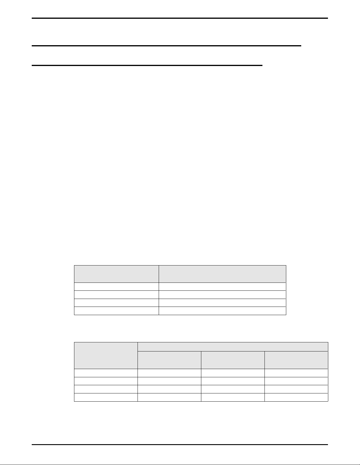
T1/E1 Fractional
Capacity
8-Port T1/E1 Board Station Board or Non-T1/E1 Line Board
16-Port T1/E1 Board Station Board or Non-T1/E1 Line Board
24-Port T1/E1 Board Non-T1/E1 Line Board
30-Port E1 Board None
There are some limitations for non-T1/E1 line board placement in slots 6, 7, and 9 when a T1/E1
•
board occupies slot 8.
T1/E1
Non-T1/E1 Line Board Allowed In Adjacent Left Slot
Board Allowed In
Adjacent Left Slot
Fractional
Capacity
8-Port T1/E1 Board Line Board Allowed Line Board Allowed Line Board Allowed
16-Port T1/E1 Board Line Board Allowed Line Board Allowed Not Allowed
24-Port T1/E1 Board Line Board Allowed Not Allowed Not Allowed
30-Port E1 Board Not Allowed Not Allowed Not Allowed
Slot 6 Slot 7 Slot 9
4 – Understanding The Board Configuration Feature
Page 9
Explaining The Software Release 10A Features IMI89–259
No matter what type of board you install in the first universal slot in the main cabinet, that slot is always
physical slot 1. The physical slot numbers begin with the first universal slot in the main cabinet and
number from left to right. The first universal slot in the expansion cabinet is physical slot number 10.
Installers need to know the physical location of the boards in order to properly wire the lines and stations.
NOTE: The left to right order for the four exclusive line board slots (slots 6 through 9) in the
main cabinet are reversed from the order that they occupied with software revisions
prior to release 10A.
The logical location of a station or a line corresponds to its relationship to the other stations or lines in the
system and is not dependent upon the board’s location in the cabinet. Therefore, if you have installed your
first station board into slot five of the main cabinet, for example, the system still refers to the first station
on that board as logical station one (station one always defaults with intercom 101).
CAUTION
This logical location is a major departure from the way the system operated prior to software release 10A.
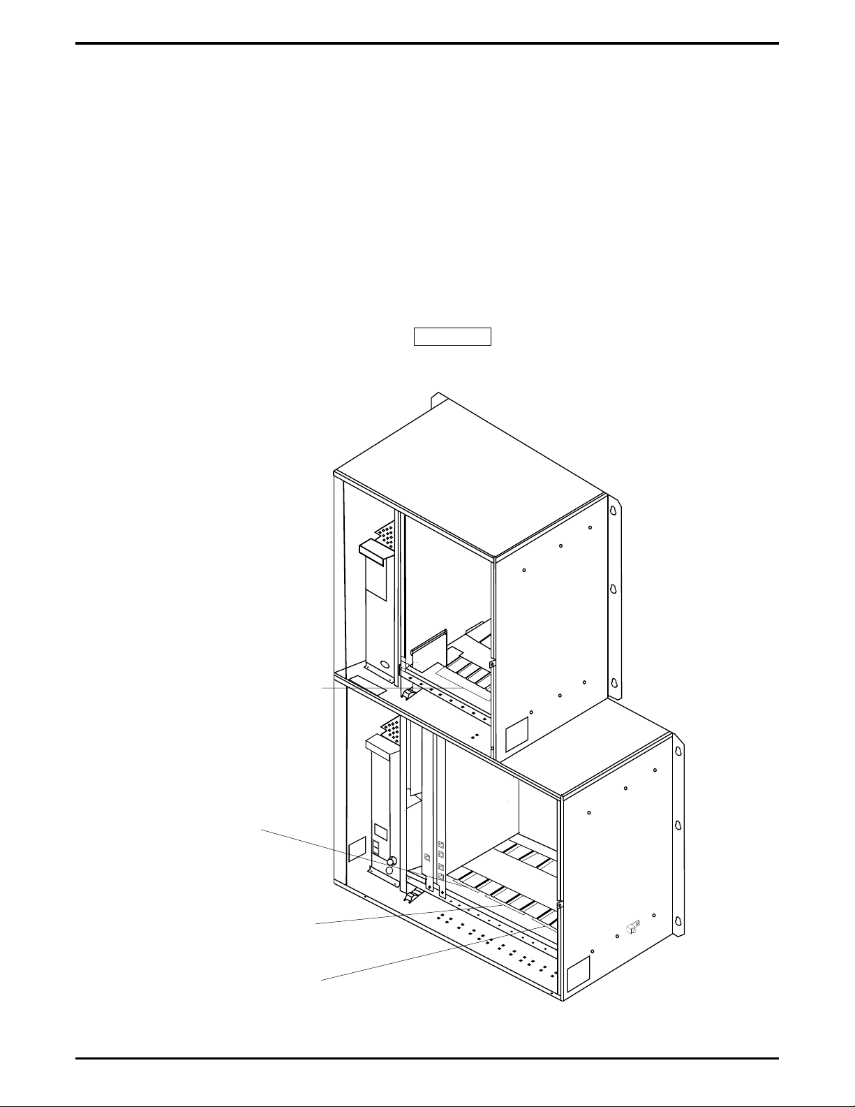
Physical Slots 10 through 16
As Viewed From Left To Right.
Universal Slots For Station or
Line Boards--Place T1/E1 Line
Boards in Slots 12, 14, and 16.
Physical Slots 1 and 2
As Viewed From Left To Right.
Universal Slots For Auxiliary
Board, Line Board, And
Station Board.
Physical Slots 3, 4, and 5
As Viewed From Left To Right.
Universal Slots For Station Or
Line Boards--Place T1/E1 Line
Boards in Slots 3 and 5.
Physical Slots 6 Through 9
As Viewed From Left To Right.
Reserved For Line Boards
--Place T1/E1 Board In Slot 8.
DXP031A.cdr
Locating The Physical Line Ports
Understanding The Board Configuration Feature – 5
Page 10

IMI89–259 Explaining The Software Release 10A Features
Describing How Automatic Configuration Works
Beginning with software release 10A, there are no dedicated station or line ports in the DXP, the system
uses an automatic configuration method to number the lines and stations. When you master clear the
system, it automatically searches for all installed line and station boards in the main and expansion
cabinet, identifies each board type and location, and automatically numbers the ports on every installed
board (see the next section, Understanding How The System Renumbers Logical Ports, for more
information on renumbering).
Understanding How The System Renumbers Logical Ports
The automatic renumbering configuration, which renumbers the logical ports, begins at the left-most
universal slot in the main cabinet and proceeds left to right. When the system has configured all of the
boards in the main cabinet, it moves to the expansion cabinet and continues searching from left to right
until it has numbered all of the lines and stations. When the configuration is finished, the line and station
ports are numbered logically from left to right in both cabinets. Remember, this automatically happens as
a result of a master clear operation.
6 – Understanding The Board Configuration Feature
Page 11

Explaining The Software Release 10A Features IMI89–259
Adding Boards Without Renumbering
When you install additional boards or relocate existing boards after the system is in service, the logical
numbers of the stations or lines on the added board continue from the last assigned logical number. For
example, if your last assigned station number was 116, the next station number will be 117, regardless of
the board’s physical slot. This is not true, however, when you remove and delete a board through
programming. After you remove and delete a board through programming, that board’s logical ports are
available for reassignment. So an added or relocated board would then take the logical port numbers from
the removed boardand not from the end of the logical sequence. For example, if your system had 64
stations served by four 16-station station boards and you were to remove a station board that had held
logical stations 1–16, the next station board that you installed would occupy logical station ports 1–16 and
not logical ports 65–80. If you were to remove an 8-port board and replace it with a 16-port board, the
first eight ports on the new board would replace the original eight logical port numbers, and the remaining
eight ports would begin with the last assigned logical port. So using this scenario, the new 16-port board
would have logical ports 1–8 and logical ports 65–72.
Understanding The Board Configuration Feature – 7
Page 12

IMI89–259 Explaining The Software Release 10A Features
Explaining Call Forward Outside System
The Call Forward Outside System (CFOS) feature allows the system to forward incoming or transferred
line calls to telephone numbers that are outside the system. The CFOS feature forwards calls over any
available outbound lines or line groups and does not use any conference circuits. Since CFOS involves
outbound calls, those calls are subject to all line access, toll restriction, and automatic route selection
restrictions normally imposed on the users. Any calls that CFOS can not service (no outbound line
available, toll restricted, and so forth), ring the system as normal calls. Note also that CFOS will not
forward calls associated with group intercoms and hunt groups. The CFOS feature is useful for
after-hours forwarding of business calls to an alternate site such as a home or cellular telephone. To help
system managers keep account of CFOS activity, the system marks CFOS calls with an F in the SMDA
records.
Users activate or deactivate CFOS by dialing a feature code, pressing a preprogrammed button or pressing
an interactive button on an LCD speakerphone. Once users activate CFOS, they select the outbound line
or line group in any of the normal line selection methods available to them. They also designate the
forward destination by dialing the number or pressing a speed dial button. (If users do not make a line and
destination choice, the system uses the most recently used selections.) DISA callers can activate and
deactivate CFOS remotely. When DISA callers activate CFOS, they receive several quick tone bursts and
the system awaits any program changes. When they deactivate CFOS, the system returns dial tone. After
they gain access to the system, they can dial the CFOS code, dial an outbound line or line group selection,
and dial the destination number. Once a user activates CFOS, it remains active and neither system resets
nor power outages will deactivate it. After activation, incoming or transferred calls to an idle
CFOS-enabled station forward outside the system to the CFOS destination over the selected outbound
line or line group. CFOS-forwarded calls are subject to the line-to-line disconnect timer action. If
time-out occurs, the system alerts the system operator. He or she can join the call as a conference member.
Before CFOS can occur for calls on incoming lines, programmers must enable those lines for CFOS
capability. Before a CFOS-enabled station can forward a call outside the system, the system must be able
to associate the call receiving line with the station.
Programmers can take action to associate a CFOS-enabled line with an individual CFOS-enabled
•
station. With this arrangement, this station is the only one that can forward to an outside destination
for a call received on that line.
At sites served by DID line blocks, programmers must enable those lines for CFOS capability but
•
they do not associate the individual lines with specific CFOS-enabled stations. The system uses the
DID translated station extension to check for the station’s CFOS forwarding ability.
When another station transfers a call to a CFOS-enabled station, the feature does not require a line
•
association with the CFOS-enabled station for it to forward the transferred call outside the system.
In this case, the system identifies the CFOS-enabled station before it makes the transfer.
In addition to the line programming action discussed previously, programmers enable CFOS
•
system-wide with a system programming choice. They then enable the feature in both station class
of service and individual station programming, and may map a CFOS button on the applicable
telephones. When mapping the button, programmers can also select a destination number; however,
any user selected destination number overrides this selection.
8 – Explaining Call Forward Outside System
Page 13

Explaining The Software Release 10A Features IMI89–259
In summary, to fully enable CFOS for use, programmers must take the following programming actions:
– enable CFOS with system programming,
– enable CFOS in station class of service,
– assign the CFOS class of service to the CFOS stations,
– enable CFOS in individual station programming,
– map a CFOS button on non-LCD telephones,
– select a destination number while mapping the CFOS button,
(this is an optional step—any user selection overrides this selection),
– enable lines for CFOS capability,
– associate a CFOS-enabled line with an individual CFOS-enabled station,
– enable DID line blocks (when used) for CFOS capability.
CAUTION
Comdial has taken reasonable steps in the design of all product features, including CFOS, which protect
against unauthorized or fraudulent access to, or use of, a system, or which protect against unauthorized,
fraudulent or unaccounted-for access to, or use of, long distance lines. However, no system is entirely
invulnerable or immune from unauthorized or fraudulent access or use, or unaccounted-for access or use,
and therefore Comdial disclaims any and all liability, and makes no warranty, express or implied, relating
to unauthorized or fraudulent access or use, or unaccounted-for access or use.
NOTES:(1) CFOS will not work on loop start lines without disconnect supervision.
(2) Calls forwarded through CFOS may experience lower audio levels due to
the normal line resistance of CO lines. Low audio level is usually only noticeable
on long line loops. If signal loss is a problem at a particular site, the installer may
need to add a line amplifier (repeater) in the lines.
Explaining Call Forward Outside System – 9
Page 14

IMI89–259 Explaining The Software Release 10A Features
Supporting the E1 Line Board
Beginning with software release 10A, the DXP supports the use of the DXPE1–nnn line board for
international applications. The E1 boardprovides 30 channels of voice transmissions over a single,
four-wire, 120 ohm cable or over two 75 ohm coaxial cables using multiplexing techniques. The DXP
accepts up to six DXPE1–nnn line boards in specified board slot locations—three in the main cabinet and
three in the expansion cabinet.
Different nations require different system parameters to enable E1 activation and operation; therefore,
Comdial supports each international application with a unique publication that provides complete
technical details for the E1 feature when used in a particular nation.
10 – Supporting the E1 Line Board
Page 15

Explaining The Software Release 10A Features IMI89–259
Understanding Station Hunting
Station hunting is available to systems with a software revision of 10A and later. Station hunting provides
a means of routing both intercom and outside calls through an installer-determined grouping of stations.
This call routing continues to a designated overflow location in case of no answer or if all stations in the
hunt group are busy. Station hunting works equally well with intercom, standard central office (CO)
lines, direct inward dialing (DID/DNIS) lines, direct inward system access (DISA) lines, and E&M tie
lines.
For station hunting purposes, stations are considered busy under the following conditions:
when they are currently connected with a call (internal or external),
•
when they have an incoming call currently ringing,
•
when they have a call on hold, in DND, call forwarded, out of service, or being intercepted by an
•
OAI application.
The installer can enable default call forwarding for a hunt group station. This feature allows the system to
forward the non-hunt group routed calls that a station receives. Calls routed to a station by the station
hunting feature ignore the default call forwarding settings. The installer can assign all types and any
number of lines to ring at a hunt group. He or she can assign the lines as direct, delayed, day 1, day 2, or
night ringing lines.
To configure station hunting, you program the following parameters:
Options: Programs the attributes, hunting type, and timers for the hunt group.
Member List: Programs the list of stations within a hunt group. This parameter shows the member
stations in their assigned hunting order and allows stations to be added, deleted or inserted at any point in
the list.
Delete: Deletes the selected hunt group from the system and frees its used resources.
CAUTION
Before you edit a member list for a hunt group, you must set the group’s hunt type to NONE; however,
before you view a hunt group’s member list, you must select a hunt type other than NONE.
Further, before you delete a hunt group, be sure that there are no un-answered calls ringing in the group
(that is, the hunt group must be idle). If the settings are not correct for either of these editing operations,
the system will not allow the operation to take place and will display messages as to the reason.
Understanding Station Hunting – 11
Page 16

IMI89–259 Explaining The Software Release 10A Features
Hunt Group Attributes
Pilot Extension: This is the extension number that callers dial to call or route calls to this hunt group.
The pilot extension number is similar to a personal intercom number, or extension number, and follows
the same numbering plan restrictions. When station hunting is used with DID/DNIS, the pilot extension is
the extension number assigned in the DID/DNIS translation table. When station hunting is used with
DISA, the pilot extension can be the extension number assigned to the single digit translation for the
digital voice announce (DVA) message associated with the DISA line.
Name: The hunt group’s name is the seven character alphanumeric name of this group that is used for
LCD display and reference.
Full Name: The hunt group’s full name is the 20 alphanumeric character name of the group that is used
by OAI applications. (Future development will support OAI access and control of station hunting.)
Direct Ring Lines: The list of lines that directly ring at this hunt group when the system is not in the
night mode of operation. This list can contain any lines in the system.
Delayed Ring Lines: The list of lines that delay ring on this hunt group. This list can contain any lines in
the system.
Day 1, Day 2, Night Ring Lines: The lists of lines that can ring this hunt group during these programmed
times. These lists can contain any lines in the system.
Member Stations: The list of stations that are members of this hunt group. This list can contain all
stations in the system but is limited to personal intercom numbers only.
Overflow Destination: The overflow destination is a station intercom number, a group intercom number,
a voice mail number, or another hunt group pilot extension where the system routes unserviced hunt
group calls.
Queue Ringing Calls: With the queue ringing calls feature disabled and if all stations in the hunt group
are busy,the system immediately routes hunt group calls to the overflow destination. With the queue
ringing calls enabled, in the case of no answer or if all stations in the hunt group are busy, hunt group
calls wait in a queue to be answered until an overflow timer times out then route to the overflow
destination.
DID/DNIS Display for Station Hunt Groups: Beginning with software release 10A, if station hunt
group members need to differentiate incoming DID/DNIS calls, programmers can take action to cause a
different display to occur. With this feature active, the display shows the incoming digits or translated
name instead of the station hunting name.
Multiple Call Handling For Station Hunt Groups: Beginning with software release 10A,
programmers can arrange the system to allow member stations within station hunt groups to handle
multiple calls. With this feature turned off, the system considers any hunt group member stations that
have calls on hold or in a park orbit to be busy to the station hunting call delivery process even though
these stations are otherwise idle. With this feature turned on, the system considers any hunt group
member stations that have calls on hold or in a park orbit to be available for additional call deliveries as
long as these stations have ring positions available (that is: an available personal intercom number, hunt
list and so forth).
12 – Understanding Station Hunting
Page 17

Explaining The Software Release 10A Features IMI89–259
Types Of Hunting
Terminal Hunting: Terminal station hunting always delivers a call to the first idle station programmed
in the hunt group. If the station does not answer within a programmed amount of time (programmed as
the Call Advance Timer), the system delivers the call to the next sequential idle station programmed in
the hunt group. The system makes no attempt to balance the distribution of incoming calls as this is a
linear search through the programmed list. The search starts at the beginning of the list for each incoming
call.
Distributed Hunting: Distributed station hunting delivers a call to the next idle station in the hunt group
after the station that received the previous call. If that station does not answer within the programmed
call advance time, the system delivers the call to the next sequential idle station programmed in the hunt
group. This hunting method is a linear search through the programmed list; however, the search starts
wherever it left off after the previous call.
Longest Idle Station Hunting: Longest idle station hunting delivers a call to the station that has been
idle for the longest period oftime since completing the last call that was routed to it by the station hunting
feature. In the case of stations with equal idle times (such as at system startup), the system picks the first
of the grouped stations with equal idle times. If that station does not answer within the call advance time,
the system delivers the call to the station with the next longest idle period.
Ring All Station Hunting: Ring all station hunting is not a true hunting method. This method delivers a
call to all idle stations simultaneously. This is a good method to use when the site requires that all calls
be answered as quickly as possible.
None (No Hunting): This selection disables hunting for the group. It allows a hunt group to be
completely programmed yet disabled. Any intercom calls to this group will receive busy and line ringing
ignores any programming within this group.
Understanding Station Hunting – 13
Page 18

IMI89–259 Explaining The Software Release 10A Features
Station Hunting Timers
Call Advance Timer: This is the time interval that a station within a hunt grouprings unanswered before
the system routes the call to the next station in the group. This timer is programmable from 10 seconds
though 5 minutes.
Overflow Timer: This is the maximum time interval that an unanswered call hunts within a group before
the system routes it to the designated overflow station for the group. This timer is programmable from 30
seconds through 15 minutes.
Recall Timer: This is the maximum time interval that an unanswered transferred call hunts within a
group before recalling to the source of the transfer. This timer is programmable from 30 seconds through
15 minutes.
Station Hunting Operation
When a system station user makes an intercom call to the hunt group pilot extension, the system rings the
first available station within the hunt group (based on the group’s selected hunting method). This ringing
appears on the station’s personal intercom. The system ignores all call announce settings as all intercom
calls into a hunt group are treated as voice announce block calls. If the station does not answer the call
within the programmed call advance time limit, the system rings the next station of the group. If no
station answers within the programmed overflow time, the call rings the designated overflow destination.
When a line rings at a hunt group, it rings at the first available station within the group (based on the
group’s selected hunting method). As the ringing line appears at the station, it follows the DXP
conventions for line appearances. If the station does not answer the call within the programmed call
advance time limit, the system rings the next member station. If no station answers within the
programmed overflow time, the system sends the call to the designated overflow destination.
The DXP supports a maximum of 32 hunt groups. Each hunt group can include the maximum number of
stations that the system can support; however, due to system memory limitations, all hunt groups can not
contain all stations simultaneously. Since the system makes a total of 16 Kbytes of memory available for
station hunt groups, you can use the following formula to determine possible station hunt group capacities.
[16384 bytes] – [(Stations per group) x (2) + (220 bytes of memory)] = memory remaining for next hunt
group
Detailing Toll/ARS 10A Software Considerations
Before you edit the toll/ARS restriction tables, you must disable the ARS system option; however, before
you view the toll/ARS restriction tables, you must enable the ARS system option.
If you do not observe these setting requirements for either of these editing operations, the system will not
allow the operation to take place and will display messages as to the reason.
14 – Detailing Toll/ARS 10A Software Considerations
Page 19

Explaining The Software Release 10A Features IMI89–259
Introducing the Visual Man-Machine Interface
The Visual Man-Machine Interface (VMMI) is menu-driven programming software for the DXP digital
communications system. The VMMI software allows the programmer to enter choices in dialog boxes
and accept the entries as valid. The VMMI program includes a detailed, context-sensitive, on-line help
file that the programmer can reference at any time during the programming sequence. The software is
accompanied by GCA40–182, Understanding The VMMI, which details start-up and operation. VMMI
runs on an IBM*-compatible personal computer (PC) with a Microsoft Windows** operating system and
at least 4 Mbytes of memory capacity. The PC communicates with the DXP through the serial data
interface. The serial data connection can be either direct or remote through a modem hookup.
* IBM is registered trademark of International Business Machines Corp.
** Microsoft and Windows are trademarks of Microsoft Corp.
Viewing A Typical VMMI Banner Screen
Introducing the Visual Man-Machine Interface – 15
Page 20

This page remains blank intentionally.
Page 21

Up-Grading Your System To Software Release 10A IMI89–259
Up-Grading Your System To
3
Up-grading to software release 10A requires that you perform the following detailed operations in the
sequence that they appear in the following pages of this publication. If you need detailed procedures for
doing these operations, refer to your DXP System Hardware Instructions and Programming Instructions
and Records service binders and to GCA40–182, Understanding The VMMI.
Software Release 10A
Converting The Database
Storing The Current DXP Database
Employ a personal computer with an XMODEM communications program and use the current embedded
MMI programming method to store the current DXP database to the computer’s hard drive. The saved
database can include any or all of the following data: system information, station parameters, line
parameters, toll restriction and automatic route selection parameters, and system speed dial numbers but it
does not include the SMDA/SMDR records. If you need these SMDA/SMDR records, you must make a
printout of them before you perform the database storage. This is necessary because this save/restore
feature does not record the stored records and they willbe lost.
Once you store the current database disconnect your computer from the DXP.
Converting The Current DXP Database
With your computer disconnected from the DXP, convert the current database to a 10A database.
1. Obtain a copy of revision 9A or later PCMMI programming software and load it on your computer.
(Remember, you can always down load the latest PCMMI software from the Comdial Technical
Services Bulletin Board by calling 1–804–978–2583 or from the Comdial home page on the World
Wide Web by connecting at: http://www.comdial.com/ ).
2. If the stored database is not at software release 9A, use the revision 9A or later PCMMI to convert the
current DXP database to a software release 9A database.
3. Use the revision 9A PCMMI to down-loadand store the software release 9A database to your
computer’s hard drive.
4. Load the new VMMI programming software on your computer, and use it to translate the stored data
base to a 10A database.
Converting The Database – 17
Page 22

IMI89–259 Up-Grading Your System To Software Release 10A
Installing The RAM Card And Software Card
Turn off the power to the DXP, and install both the RAM card (DXRAM–EXPC.) and the software
memory card (DXPSW–DLRC) on the central processor unit (DXCPU–68K) circuit board of the DXP
digital communications system.
Preparing A Static-Safe Work Area.
CAUTION
Electronic circuit boards are susceptible to damage caused by electrostatic discharge and must be
handled accordingly. Refer to the Comdial publication IMI01–005, Handling Of Electrostatically
Sensitive Components, for general information. Specific handling precautions are also included in this
installation instruction. The expanded memory card (DXRAM–EXPC) and the system software memory
card (DXPSW–DLRC) are supplied in static protection bags. Do not open a static protection bag prior to
installation time.
When servicing electronic circuit boards, it is a good practice to do so at a static-safe work area prepared
ahead of time for this purpose. The illustration details a typical static-safe work area.
18 – Installing The RAM Card And Software Card
Page 23

Up-Grading Your System To Software Release 10A IMI89–259
Common
Equipment
Cabinet
Conductive
Mat
Backboard
1 Meg Ohm
Resister
dxp040
Earth
Ground
Static Discharge
Wrist Strap
Providing Static Protection At The Cabinet Location
Static
Wrist
Common Point Ground
Strap
ESD Protective
ESD Protective
Worksurface
Mat
Typical Earth
Ground
Static 2
ESD Protective
Mat
Creating A Static Safe Work Area
Installing The RAM Card And Software Card – 19
Page 24

IMI89–259 Up-Grading Your System To Software Release 10A
Installing The Cards
1. Loosen the retaining hardware and remove the front panel from the DXP main cabinet.
2. Turn off the AC power switch, and disconnectthe AC power cord from the AC outlet. Disconnect the
cable of the optional battery back-up from the main cabinet power supply.
3. Place a conductive mat in front of the cabinet area and ground the mat to a good earth ground (the
third wire ground of the AC power line is an acceptable grounding point). The grounded conductive
mat will provide a safe static electric discharge path.
4. Install the static discharge wrist strap (supplied with the main cabinet) on your bare wrist; adjust it for
a snug fit. Be sure that the strap is touching bare skin and is not isolated by clothing. Connect the
wrist strap cord between the wrist strap and an AC orearth ground.
NOTE: With the common equipment in the installed position, the ground lug on the side of the
cabinet is an appropriate grounding point since it should have a heavy ground wire
connected between it and a good earth ground.
5. Locate the DXCPU–68K circuit board, loosen the retaining screws, remove it from the DXP main
cabinet, place it in a static protection bag, and transport it to the static-safe work area.
6. At the static-safe work area, with your wrist strap in place, remove the DXCPU–68K circuit board,
the new DXRAM–EXPC. expansion memory card and the new DXPSW–DLRC software memory
card from their static protection bags.
7. Refer to illustration and remove the currently installed memory cards from the DXCPU–68K board.
8. Orient the DXCPU–68K board and the new memory cards as shown in the illustration, and attach
them with the supplied hardware. (The screws and standoffs between the cards are essential to ensure
proper grounding.)
9. Place the old memory cards in static protection bags and save them for later return for credit. Place
the DXCPU–68K board and newly installed memory cards into a static protection bag and transport
back to the DXP main cabinet.
10. With your wrist strap properly grounded, remove the DXCPU–68K circuit board from the static
protection bag. Orient it with the top and bottom guides in the main cabinet board cage, and press it in
firmly until the board edge connector properly mates with the backplane connector.
CAUTION
When pressing the DXCPU–68K board into place, press it only at the extractor lever locations. If you
apply pressure at other locations, you may damage the board assembly.
11. Make a final inspection to ensure that the DXCPU–68K circuit board is in the correct slot, oriented
correctly and mated properly; then install and tighten the supplied screws to secure it to the board
cage.
20 – Installing The RAM Card And Software Card
Page 25

Up-Grading Your System To Software Release 10A IMI89–259
DXP022
#4-40 Machine Screw
(Two Places
DXPSW-XXXXX
Circuit Card
Front Panel
DXRAM-XXXXX
Circuit Card
Front
Panel
1/4 Hex, #4-40
M-F Spacer,
.625 Long
#4 Lockwasher
Connectors
DXCPU
Circuit Board
#4-40 Machine Screw
#4 Lockwasher
DXPSW-XXXXX
Connectors
DXRAM-XXXXX
1/4 Hex, #4-40
M-F Spacer,
.625 Long
#4 Lockwasher
DXCPU
Board
#4-40 Hex Nut (3X)
Installing The Memory and Software Cards
Installing The RAM Card And Software Card – 21
Page 26

IMI89–259 Up-Grading Your System To Software Release 10A
Master Clearing The System
1. If you do not master clear the system, it is possible the DXP will not perform properly with the new
memory card. The DXCPU–68K board provides a method for the master clear to occur automatically
at the initial power up after you have changed or upgraded the software card. When you perform an
upgrade, you must execute the following sequence of events exactly as they are stated here:
2. On the DXPCPU–68K circuit board, set DIP switch 8 to its ON position. This step enables the DXP
to perform the master clear and is a required step; otherwise, the software upgrade will not occur and
the system will not operate.
3. Connect the AC power cord to the AC outlet and turn on the AC power switch. At power up, the DXP
automatically executes a master clear operation. Observe that the LED indicators on the
DXCPU–68K board, the DXSRV services board, and all installed station and line boards flash in a
random pattern during the master clear sequence. After the master clear sequence is complete, the
indicators on the DXCPU–68K and DXSRV boards turn on steady and the indicators on the station
and line boards wink ON for four seconds and OFF for four seconds.
3. After power up, set DIP switch 8 to its OFF position.
4. Press the RESET button on the CPU board to reset the system.
NOTE:The system performs the automatic master clear one time following the initial power up
after you have up-graded the software. It will not perform an automatic master clear
operation again after subsequent power ups. Because of this, you can leave DIP switch 8
ON if you wish. Leaving it ON will ensure that the DXP will always power up in a master
cleared and operational mode after you have performed a software upgrade. However,
by turning DIP switch 8 OFF, you prevent the DXP from becoming operational at power
up after you have performed a software upgrade. This is good because, should you forget
to save your database, it gives you an opportunity to reconsider your actions before the
DXP erases the current database.
5. Replace the front panel onthe DXP main cabinet.
22 – Master Clearing The System
Page 27

Up-Grading Your System To Software Release 10A IMI89–259
DXCPU-68K
DXRAM-xxx
Reset Button
1234
1234
OFF
ON
1
2
3
4
5
6
7
8
DXSW-xxx
Set DIP Switch 1 ON
For Fixed Data Port
Parameters.
Set DIP Switch 8 ON
For Master Clear Upon
Initial Power Up After
Software Upgrade.
DXP025
Locating DIP Switch 8 and the Reset Button
Up-Loading The Converted Database To The DXP
Connect your computer to the DXP and use VMMI to up-load the translated 10A database to the DXP.
(Note that with VMMI, you do not need the XMODEM communications program that you needed to
store the current database)
Up-Loading The Converted Database To The DXP – 23
Page 28

This page remains blank intentionally.
Page 29

LIMITED WARRANTY
Comdial Corporation (Comdial) warrants that under normal operating conditions, this Equipment (except for fuses, lamps, and other
consumables) will be free from defects in material and workmanship for a period of twenty-four (24) months from the manufacturing date
stamped on the Equipment. Comdial’s sole obligation under this warranty or under any other legal obligation with respect to the Equipment is to
repair or replace, at its option, the Equipment if it is deemed defective by Comdial during the warranty period free of charge with new or
refurbished equipment or parts, at Comdial’s option, when the Equipment is returned to Comdial, freight or postage prepaid, during the warranty
period. This warranty does not apply if, in the sole judgement of Comdial, the Equipment has been installed or used in combination or in
assembly with products not supplied by Comdial and which are not compatible or inferior quality, design or performance, or the Equipment has
been otherwise misused, abused, accidentally damaged, or damaged or malfunctions or fails to function as a result of acts of God such as fire,
flood, or lightning or other incidence of excessive or insufficent voltage or failure to follow instructions. Repair or alteration of this Equipment
other than as specifically authorized by Comdial or its authorized repair agent is prohibited and will void this warranty. This warranty does not
cover costs associated with installation, removal, or reinstallation of the Equipment. Comdial does not warrant that the Equipment is compatible
with all telephone or switching systems. THIS WARRANTY IS EXCLUSIVE, BEING IN LIEU OF ALL OTHERWARRANTIES, EXPRESS
OR IMPLIED, INCLUDING, BUT NOT LIMITED TO, ANY IMPLIED WARRANTY OF MERCHANTABILITY OR FITNESS FOR A
PARTICULAR PURPOSE. WITHOUT EXPANDING UPON THE FOREGOING WARRANTY, THE MAXIMUM LIABILITY OF
COMDIAL UNDER ANY WARRANTY, STATUTORY, EXPRESS OR IMPLIED, IS LIMITED TO THE PURCHASE PRICE OF THE
EQUIPMENT. COMDIAL SHALL HAVE NO RESPONSIBILITY FOR DAMAGE TO PROPERTY OR ANY OTHER LOSS OR INJURY,
INCLUDING CONSEQUENTIAL AND/OR INCIDENTAL DAMAGES, RESULTING FROM THE POSSESSION, OPERATION OR USE
OF THE EQUIPMENT, ALL SUCH CLAIMS BEING HEREBY EXPRESSLY WAIVED. THE PURCHASER’S EXCLUSIVE
WARRANTY AND REMEDY SHALL BE ONLY AS STATED HEREIN.
This warranty gives you specific legal rights and you may also have other rights which may vary from state to state. Some states do not allow
limitations on how long an implied warranty lasts or the exclusion or limitation of incidental or consequential damages, so the above limitations
may not apply to you.
If the Magnuson-Moss Act should be held to apply to the sale of the Equipment by a court of competent jurisdiction, the implied warranty of
fitness for a particular purpose shall extend for one year from the date of manufacture.
No Comdial dealer nor any other person or entity other than Comdialmay extend or modify this warranty, and no such modification or extension
shall be effective unless it is in writing.
This manual has been developed by Comdial Corporation (the “Company”) and is intended for the use of its customers and service personnel.
The information in this manual is subject to change without notice. While every effort has been made to eliminate errors, the Company
disclaims liabilityfor any difficulties arising from the interpretation of the information contained herein.
The information contained herein does not purport to cover all details or variations in equipment or to provide for every possible contingency to
be met in connection with installation, operation, or maintenance. Should further information be desired, or should particular problems arise
which are not covered sufficiently for the purchaser’s purposes contact, Comdial, Inside Sales Department, P.O. Box 7266, Charlottesville,
Virginia 22906.
Page 30

R
Charlottesville, Virginia 22901-2829
World Wide Web: http://www.comdial.com/
Printed in U.S.A. 9/96
IMI89–259.01
 Loading...