

Page 1

’
:
,
DXP
Training Manual
COMDIAL
Page 2

DXP Correspondence Manual
L
Contents
Contents
Section
Chapter One: Introducing The DXP
1.1
1.2
1.3
1.4
1.5
1.6
1.7
1.8
1.9
1.10
1.11
1.12
Introducing This Course
Using The Video Series
Introducing The DXP Hardware
Introducing The DXP Main Cabinet
Using The DXP Modem
Using The Battery Backup
Identifying The Mandatory DXP Boards
Identifying The Station Boards
Identifying The Line Boards
Using The Auxiliary Board and Add-On Cards
Using The Conference Board
Introducing The Expansion Cabinet
.................................................................................
.................................................................................
...............................................................................
.............................................................................
......................................................................
........................................................................
.......................................................................
Page Number
. . . . . . . . . . . . . . . . . . . . . . . . . . . . . . . . . . . . . .
....................................................................
..............................................................
.......................................................
..........................................
............................................................
..~.......................
l-l 1
1-14
1-16
1-16
l-l
l-l
l-2
l-3
l-4
l-5
l-5
l-6
l-9
1.13
Concluding Chapter Three
Chapter One Review Questions
...........................................................................
1-17
................................................................... 1-18
Con tents-i
Page 3

Section Number
Page Number
Chapter Two: Planning An Installation
2.1
2.2
2.3
2.4
2.5
2.6
2.7
2.8
2.9
Introducing Chapter Two
Ordering The Right Equipment
Evaluating The Installation Site
Planning The Dedicated Equipment Room
Using The Right Tools
Preparing An MDF Diagram
Checking The Hardware
Testing The Stations
Concluding Chapter Two
...............................................................................
...................................................................................
..........................................................................
................................................................................ 2-6
.......................................................................................
.............................................................................
Chapter Two Review Questions
Chapter Three: Installing The DXP
3.1
3.2
Introducing Chapter Three
Mounting The Main Cabinet
.............................................................................
..........................................................................
...........................................................
......................................................................
..................................................................... 2-3
.................................................................... 2-9
.................................................................. 3-l
2-I
2-l
2-2
....................................................
2-3
2-4
2-5
2-8
.2-8
3-l
3-2
.
3.3
3.4
3.5
3.6
3.7
3.8
3.9
3.10
3.11
3.12
3.13
3.14
3.15
3.16
3.17
Mounting The Expansion Cabinet
Grounding The System
..................................................................................
Installing The Power Supply
Connecting A Battery Backup
Installing The Boards
Connecting The Lines
Connecting The Stations
Testing The Stations
..................................................................................... 3-7
..................................................................................
..............................................................................
.....................................................................................
................................................................ 3-3
.......................................................................... 3-4
....................................................................... 3-6
Connecting An External Paging Device
Connecting A Modem
Connecting A Music Source
Installing The Ring Generator
Connecting The PC Attendant
Connecting A Printer
Concluding Chapter Three
..................................................................................
........................................................................
...................................................................... 3-15
.....................................................................
...................................................................................
...........................................................................
3-3
3-10
3-l 1
3-12
.....................................................
3-13
3-14
3-15
3-16
3-17
3-18
ii-Con tents
Chapter Three Review Questions..
........................................................
.:
.....
3-l 9
Page 4

DXP Correspondence
Manual
Contents
Section
Chapter
4.1
4.2
4.3
4.4
4.5
4.6
4.7
4.8
Chapter Five: System Programming
5.1
5.2
Four: Programming The DXP
Introducing
Using Other publications
Two waystoProgram
Connecting Data Devices..
Using A Modem
Using The DXP Menus
Accessing
Programming..
...........................................................................
..............................................................................
...................................................................................
............................................................................
............................................................................................. 4-5
..................................................................................
the Main Menu..
...........................................................................
Understanding The Main Menu
Chapter Four Review Questions
Introducing System Programming
Master Clearing The System
.......................................................................... 5-2
.................................................................... 4-8
.................................................................... 4-9
...............................................................
................................................................
Page Number
............................................................
4-1
.4-
1
.4-2
.4-3
.4-4
4-6
.4-7
5-I
.5-l
..
5.3
5.4
5.5
5.6
5.7
5.8
5.9
5.10
5.11
5.12
5.13
5.14
5.15
5.16
5.17
Setting The System Defaults
Terminal Setup..
LCD Messages
Save/Restore Database
Serial Ports
SOHVA
Speed
Table Programming..
Dial Programming
Time and Date
System Timing
System Parameters
Paging Zones..
Change Password
Feature Renumbering
Programming The
Major Alarm Reporting
............................................................................................
...............................................................................................
................................................................................. 5-10
................................................................................................... 5- 12
............................................................................. 5- 17
(System
Clock) .................................................................... 5-19
.............................................................................................
.......................................................................................
..............................................................................................
.........................................................................................
..................................................................................
Tl
Parameters
...............................................................................
.......................................................................... 5-4
-5-7
5-8
..................................................................... 5-l 5
5-20
5-26
5-32
5-34
5-36
................................................................ 5-38
5-38
Chapter Five Review Questions..
.................................................................
I
5-39
.
Con tents-iii
Page 5

Section
Page Number
Chapter Six: Station COS Programming
6.1
6.2
6.3
6.4
6.5
6.6
6.7
6.8
6.9
6.10
6.11
6.12
6.13
Introducing Station
Account Codes
Automatic Hold
Background Music
Call
Cost Display (Display Of Calls).
Call Forward
Call
Park.. ......................................................................................................
Call Pick-Up
................................................................................................... 6-6
Call Waiting (Tone)
Camp-On Programming..
Do Not Disturb Programming..
Exclusive Hold
Executive Override Programming
COS
Programming..
............................................................................................... 6-2
.............................................................................................
......................................................................................... 6-3
................................................................................................. 6-4
...................................................................................... .6-7
............................................................................... 6-8
..................................................................... .6-9
............................................................................................... 6-9
. . . . . . . . . . . . . . . . . . . . . . . . . . . . . . . . . . . . . . . . . . . . . . . . . . . . . . . .
...........................................................
.................................................................
.......................................................
6-1 .
6-l
6-2
.6-3
.6-6
.6-9
6.14
6.15
6.16
6.17
6.18
6.19
6.20
6.21
6.22
6.23
6.24
6.25
6.26
6.27
6.28
Idle Line Programming
IST Distinctive Ringing
LCD Messaging
Meet
Me
Answer Page..
........................................................................................... 6-10
Message Deposit (Response Messaging)
Message Wait Originate (Message Waiting)
Music
Paging Receive
Paging Transmit
Or
Tone
On
............................................................................................ 6-12
...........................................................................................
................................................................................ 6- 10
............................................................................... 6-10
...............................................................................
.....................................................
..............................................
..............................................................................
Hold
Ringing Preference (Ringing Line Preference)
Day Route Access/Night Route Access
....................................................... 6-14
Day Restriction Level/Night Restriction Level..
System Speed Dial Groups
Directed Station Hold
Remote Station Disable
.......................................................................... 6-l 6
...................................................................................
................................................................................ 6-l 6
6-l
6-l 1
.6-l
1
6-12
6-13
........................................... 6- 13
.........................................
6-15
6-16
1
6.29
6.30
iv-Con tents
Station Monitoring
Line Answer
......................................................................................
6-
17
................................................................................................. 6-18
Page 6

DXP Correspondence Manual
Contents
Section
6.31
6.32
6.33
6.34
6.35
6.36
6.37
6.38
6.39
6.40
6.41
6.42
6.43
Line Originate
Periodic
Line Tone.. .....................................................................................
Maximum Call Duration
Line Group Access
Line Group Queue
Line-To-Line Transfer
Voice Announce Block
Internal IST Flash
Forced Account Codes..
Allow Busy Display
Clear Major Alarm Ring
.............................................................................................
..............................................................................
.......................................................................................
........................................................................................
(Unsupervised Conference)
................................................................................
.........................................................................................
...............................................................................
(Display Of Busy Status)
..............................................................................
Handset Volume On Impact Telephones
Restrict ARS Ho&flash
..............................................................................
Page Number
6-18
6- 19
6- 19
6-19
6-20
.................................... 6-20
6-20
6-21
6-22
...........................................
.....................................................
6-22
6-22
6-23
6-23
.
6.44
6.45
Chapter Seven: Station Programming
7.1
7.2
7.3
7.4
7.5
7.6
7.7
7.8
7.9
7.10
Quick Transfer .............................................................................................
Enhanced LCD Display
Chapter Six Review Questions
Introducing Station Programming
Personal
Station Name
Class
Intercom Number
..................................................................................................
Of Service ............................................................................................
...............................................................................6-24
....................................................................
. . . . . . . . . . . . . . . . . . . . . . . . . . . . . . . . . . . . . . . . . . . . . . . . . . . . . . . . . . . .
..................................................................
............................................................................7-2
Speed Dial Sets ..............................................................................................
Idle Line Priority
Intercom Hunt List
............................................................................................
.........................................................................................
Group Intercom Access..................................................................................
Prime Line Programming.. ............................................................................
Tone Or Voice Signaling (Tone
First)
6-24
6-25
7-1
7-1
7-2
7-2
7-3
7-3
7-3
7-4
.7-4
..........................................................
.7-5
7.11
7.12
7.13
7.14
Call Announce Beeps (Call Announce Tone Bursts).
...................................
Default Forward Type ...................................................................................
Forward RNA Ring Busy (Enhanced Call Forwarding)
Flexible
Ringing Assignments .......................................................................
...............................
7-5
7-6
I
7-7
7-7
Con tents-v
Page 7

Contents
DXP Correspondence Manual
Section
7.15
7.16
7.17
7.18
7.19
7.20
7.21
7.22
7.23
7.24
7.25
7.26
7.27
Page Number
Personalized Ringing Tone
LCD Contrast
Service Observing
.................................................................................................
........................................................................................
Day Exception Number/Night Exception Number .....................................
SOHVA Beeps (SOHVA Tone Bursts)SOHVA Groups..
Busy On SOHVA
Pick-Up Groups
.........................................................................................
...........................................................................................
Through Dialing (Thru-Dialing)
Single Line Proprietary Telephone TAP Button..
Ringing On Busy (Enhanced Subdued Ringing)
Allow Ringer Off (Ringer Volume Off)
Station Disable
DWBLF
............................................................................................
Consoles
Installed .......................................................................
...........................................................................
7- 10
.7-
..........................
.7-l
7-11
7-11
..................................................................
........................................
.........................................
.....................................................
7-12
7- 12
7-12
7- 13
7- 14
7-14
.7-9
7-9
11
1
.
7.28
7.29
7.30
7.31
7.32
7.33
7.34
7.35
7.36
7.38
7.39
Chapter Eight: Programming The Lines
8.1
Programming Port (Database Programming Station).
Automatic Voice Mail Transfer On Busy ...................................................
Headset
........................................................................................................
Attendant Position (Alternate, Overflow)
Extended DTMF Dialing
.............................................................................
Interactive Button Support (Softkeys Setup) ..............................................
IST Hold Confirmation
Transfer Ring Cadence
Ring Back On Busy
Telephone Types (Phone
Copy Model Programming..
Chapter Seven Review Questions
Introducing Line Programming
................................................................................
................................................................................
.....................................................................................
Types)
.................................................................
........................................................................
................................................................
.........................................................
......................................................................
.................................
7-15
.7-l
7-15
....................................................
7-16
7-16
.7-17
7-18
7-18
7-19
.7-2 1
.7-22
7-23
8-l
8-l
5
8.2
8.3
8.4
8.5
vi-Con tents
Line Name
Line Type
Line Disable
......................................................................................................
.......................................................................................................
............................................................................................I......
Music Or Tone On Hold
...............................................................................
8-2
8-2
8-4
8-4
Page 8

Section
Page Number
8.6
8.7
8.8
8.9
8.10
8.11
8.12
8.13
8.14
8.15
8.16
8.17
8.18
8.19
8.20
Automatic Privacy (Privacy Release)
SMDR
Cost Incoming
Pad Level-Transmit, Receive
Dialing Mode
Abandon Hold Release
Positive Disconnect Time
Toll Groups
DTMF Level
Busy Lead Detection..
Disconnect Supervision
Caller ID Active
Voice Mail ID
DISA and DISA Voice Options
Line Group Programming
............................................................................................................
...............................................................................................
......................................................................
.................................................................................................
...................................................................................
..............................................................................
.................................................................................................... 8-9
..................................................................................................
..................................................................................
................................................................................
...........................................................................................
..............................................................................................
................................................................... 8-l 1
............................................................................
............................................................
8-5
8-5
8-5
8-6
8-7
8-8
8-8
8-9
8-10
8-10
8-10
8-l 1
8-12
8.21
8.22
8.23
8.24
8.25
8.26
Chapter Nine: Intercom Numbers
9.1
9.2
9.3
9.4
9.5
Copy Model Line
Direct Inward Dialing (DID) Support..
DID Options
DBXDNIS
Direct Inward System Access (DISA)
Enabling Or Disabling DISA
Chapter Eight Review Questions
Introducing Intercom Programming
Modifying Intercom Numbers
Adding Intercom Numbers
Removing Intercom Numbers
Renumbering Intercom Numbers
Chapter Nine Review Questions
Translation Tables
........................................................................................
.................................................................................................
..................................................................... 8-17
Lines
. . . . . . . . . . . . . . . . . . . . . . . . . . . . . . . . . . . . . . . . . . . . . . . . . . . . . . . . . . . . . . . . . . .
.......................................................................
............................................................................. 9-3
.......................................................................
8-12
........................................................ 8-l 3
8-14
.........................................................
............................................................. 8-l 9
.................................................................
...............................................................
..................................................................
.................................................................... 9-5
8-18
8-20
9-1
9-l
9-2
9-3
9-4
,
Page 9

Section
Page Number
Chapter Ten: SMDAISMDR
10.1
10.2
10.3
10.4
Introducing
SMDABMDR
SMDABMDR
Parameters
Account Code (System Parameters)
Emergency Numbers..
10.5 Authorization Code
Chapter
Chapter Eleven: Toll Restriction
1
1.1
Introducing Toll Restriction..
Ten Review Questions.. ..................................................................
11.2 Restriction Levels
11.3 Toll Groups
..................................................................................................
11.4 Restricted Numbers
11.5 Exception Numbers
Chapter Eleven
Review Questions.. .............................................................
. . . . . . . . . . . . . . . . . . . . . . . . . . . . . . . . . . . . . . . . . . . . . . . . . . . . . . . . . . . . . . . . . . . . . . . . . . .
Programming
...........................................................................
..................................................................................
......................................................................................
........................................................................................
......................................................................................
......................................................................................
10-l .
................................................... 10-l
10-2
.............................................................
10-5
1 O-7
10-7
10-8
. . . . . . . . . . . . . . . . . . . . . . . . . . . . . . . . . . . . . . . . . . ..‘......................
.......................................................................
11-1
1 1 -
1
11-2
11-3
11-3
11-4
1 l-5
Chapter Twelve: Automatic Route Selection
12.1
12.2
12.3
12.4
12.5
12.6
Introducing Automatic Route Selection
ARS Enable.. ................................................................................................
Line Groups for
Route Tables
(ARS) .....................................................................................
Costing Information (ARS)
...................................................................................
ARS
..........................................................................
Automatic Route Selection for Speed Dial Numbers..
Chapter Twelve Review Questions..
.
Chapter Thirteen: System Printouts
13.1
13.2
Introducing System Printouts..
Identifying System Printouts
..~...................................~......,......,.....,.
.....................................................................
........................................................................
. . . . . . . . . . . . . . .
.......................................................
............................................................
Chapter Thirteen Review Questions ............................................................
..m..........................m..
12-1
12-1
12-2
12-2
12-3
12-6
................................
12-7
12-8
13-1
13-l
13-2
13-3
viii-Con tents
Page 10

Section
Page Number
Chapter Fourteen: Diagnostics
14.1 Introducing Diagnostics
14.2
14.3
14.4
14.5
14.6
14.7
14.8
14.9
14.10
Initialize Diagnostic Data
ROM Checksum Verification
Scratch RAM Test
Non Volatile RAM test
Time Switch Memory Test
Main CPU DTMF Receiver Test
AUX Board DTMF Receiver Test..
Speaker Coefficients
CPU Board and DIP Switches
...............................................................................
.............................................................................
........................................................................................
................................................................................
...................................................................................
Chapter Fourteen Review Questions..
Chapter Fifteen: Peripherals
15.1
Introducing the DXP Peripheral Equipment
..........................................................................
.....................................................................
14-1
14-1
14-2
......................................................................
14-2
14-2
14-2
.......................................................................... 14-3
.................................................................
.............................................................
14-3
14-3
14-4
.....................................................................
14-4
.......................................................... 14-5
15-I
................................................ 15-
1
.
15.2
15.3
15.4
15.5
15.6
15.7
Caller ID Programming..
..............................................................................
Tracker Paging System Programming
Digital Voice Announce Programming..
PC Attendant Position Programming
Voice Mail Programming
Modem Setup
.............................................................................................
...........................................................................
Chapter Fifteen Review Questions..
.........................................................
...........................................................
.........................................................
...................................................... 15-6
15-12
15-14
15-19
15-20
15-2
15-4
Con tents-ix
Page 11

II
Introducing The DXP
Introducing The DXP
1.1
1.2
1.3
1.4
1.5
1.6
1.7
1.8
Introducing This Course .......................................................................
Using The Video Series ........................................................................
Introducing The DXP Hardware ..........................................................
The
DXP’s
Introducing The DXP Main
Using The DXP Modem ......................................................................
Using The Battery Backup ................................................................... l-5
Identifying The Mandatory DXP Boards .............................................
Interface Boards
Services Board .............................................................................
CPU Assembly
RAM
Software Card
Identifying The Station Boards
Analog Station Board..
modular design
Card.. .................................................................................. 1-8
. . . . . . . . ..L.............................................................~......
..........................................................
Cabinet .................................................... l-4
...........................................................................
.............................................................................
..............................................................................
............................................................
.................................................................
l-3
l-6
l-7
l-7
l-8
l-9
l-l
l-l
l-2
l-3
l-5
l-6
l-9
1.9
Digital Station Board
Industry Standard Telephone Board..
Wiring The Stations
Identifying The Line Boards ..............................................................
Loop start line board
Multipurpose line board..
TI board..
DID board
.................................................................................... 1-13
.................................................................................. l-13’
...................................................................
.........................................
...................................................................
..................................................................
........................................................... 1-12
l-9
l-10
l-10
1-12
l-11
Chapter Con tents
Page 12

1.10
Using The Auxiliary Board and Add-On Cards ................................
DTMF Tone Card ......................................................................
1-14
1-14
Communications Card................................................................
1-15
Synchronization Card................................................................. l-15
1.11
1.12
Using The Conference Board.............................................................
Introducing The Expansion Cabinet
...................................................
1.13 Concluding Chapter One ....................................................................
Chapter One Review Questions ..........................................................
1-16
1-16
1-17
l-18
Chapter Con tents
Page 13

DXP Correspondence Manual
Introducing The DXP
Introducing The DXP
1.1
Introducing
This book is part one of Comdial Corporation’s three-part DXP
Certification process. You must pass all three portions of the training
to become an authorized DXP installer.
I
This Course 1o
Basic DXP course-a three-day class that introduces you to the
fundamentals of DXP installation, programming, and operation. The
final stage of your certification is the two-day Advanced DXP course,
which covers some of the advanced features and peripherals, like the
Tl,
In addition to your correspondence manual, you should have received
a series of training videotapes and the DXP System Manual. If you
study all of these materials carefully, completing this correspondence
course is fairly simple. You will find study questions at the end of
each chapter in this manual; the answers to these questions are in the
back of the book.
Keep in mind that the purpose of this course is to provide you with a
basic overview of the DXP system and to prepare you for the
classroom portion of the training.
For more information about the DXP, or for additional training
materials, call Comdial’s Inside Sales Department at l-800-347-1432.
rice
you complete the correspondence course, you can enroll in the
Digital Voice Announce (DVA), and DID for example.
introducing The DXP I - 1
Page 14

Introducing The DXP
DXP Correspondence Manual
1.2
Usinc
_
----
3
The
Video Series
The following list details the purpose of each of the videos in this
series.
l
When you have finished Part One,
Introducing The DXP, you
should be acquainted with the DXP hardware and
printed-wire-boards, and you’ll be ready to move on to Part
Two, Planning an Installation.
l
Part Two,
Planning an Installation,
evaluates the preliminary
considerations for installation and programming. In Part Two,
we’ll survey the installation site and show you some of the
pre-installation steps.
l Part Three, Installing The
DXP,
takes you step-by-step through
the DXP installation, including hardware, software, wiring,
and optional peripherals.
l In Part Four, Programming The DXP, we’ll be programming
the system, and we’ll explain the features and applications that
we use on that system; Any additional DXP features will be
covered in the classroom portion of the training.
l
Part Five,
of the
Operating The Telephones,
DigiTech
II, Impact, and Industry-standard telephones
gives you an overview
and explains how they operate through the DXP. The video
also discusses individual station programming that the
end-user can perform.
l
Part Six,
Advanced DXP Features,
discusses a few of
DXP’s
more advanced features.
When you have finished with all of this manual and have watched all
of the correspondence training tapes, you should be familiar with the
following:
-
The versatility of the DXP system and how to best utilize the
features and applications to meet your customer’s needs;
-
The DXP components-including system hardware, software,
printed-wire boards, and telephones;
-
Installation, wiring, and system checkout;
-
Programming of a DXP system and stations,
-
and finally, using the various telephones with the DXP.
By watching the training tapes and completing this correspondence
course, you will be prepared to move on to the DXP classroom
training. At the beginning of the in-class training, you will be given a
pre-test based on the videos and correspondence course.
I-
2 Introducing The DXP
Page 15

1.3
Introducing
The DXP
Hardware
The DXP has a modular design with all of the system’s switching
circuitry housed on printed-wire-boards that simply slide in and out of
the cabinets. Installing the DXP is quick and easy, and the variety of
boards makes the system versatile enough to meet virtually any
business’s needs. The DXP is comprised of two cabinets, the main
cabinet and the expansion cabinet.
The DXP’s Modular Design
One of the benefits of the DXP is its flexibility, and that flexibility
comes from its modular design.
The term “Modular design” means that the system’s electronic
components are housed in a series of self-contained printed wire
boards that can be arranged quickly and easily into a variety of
configurations.
By changing the printed wire boards, you can find the right
combination of features and telephone capacities to suit the needs of
your particular client.
For example, if a client desires maximum line capacity, you can
configure a fully-equipped DXP main cabinet and expansion cabinet
for a total of 120 lines on 16 telephones. If a client wants maximum
telephone capacity, you can configure the system to provide 32 lines
on 192 telephones.
The number and type of boards that you install determines the DXP’s
line and telephone capacities. You can also update the DXP’s software
card to enhance the features and capabilities of the DXP.
The DXP allows you to make many of these modifications without
disrupting the client’s normal telephone service.
Introducing The DXP 7 - 3
Page 16
Introducing The
DXP
DXP Correspondence Manual
1.4
Introducing
The DXP Main
Cabinet
The main cabinet (DXCBM) contains the main power supply and up
to 12 printed-wire-boards. The cabinet is 26 inches wide, 19 inches
high, and twelve inches deep, and it’s comprised of the following
components:
l an external, ventilated sheet-metal housing with detachable
front cover,
l the card cage-the metal frame into which you insert the
printedwire-boards,
.
and the backplane-a large printed-wire-board that provides
the circuitry to connect the individual boards together.
When you first open the main cabinet, you will see an empty space
where the power supply is to be mounted. The power supply provides
DC operating power for the DXP printed-wire boards and also for the
individual digital stations as well. The power supply is shipped
separately, and we’ll cover it later in this manual.
The space directly above the power supply is reserved for the ring
generator. Industry-standard telephones require voltage to enable
ringing and to turn on the message-waiting lights; the ring generator
supplies the required voltage to all of the IST stations on the DXP.
You must have a ring generator if you are going to use IST stations,
and you must have a ring generator in each cabinet that supports IST
stations. It’s a good idea, therefore, to plan on configuring all of your
IST stations through one of the cabinets.
.
Moving from left to right in the main cabinet, the slots for
boards are as follows:
-
Interface board
-
Services board
-
CPU Board (RAM Card/Software Card)
-
Universal 1 / Auxiliary Board
-
Universal 2 / Auxiliary Board
-
Universal slots
-
Line slots 4, 3, 2, 1.
For more information on the DXP main cabinet, see
IMI66-085.
3,4,5
GCA40-069
the
12
and
1 - 4 Introducing The DXP
Page 17
I.5
Using The DXP
Modem
The space directly below the interface board (slot one) is reserved for
the DXP modem, DXMDM. The modem allows you to service and
program the DXP from a remote location. The modem runs at a
maximum of 2400 baud, and it receives its power from the
power supply. Please note that this is a proprietary modem. For more
information on the modem, see
IMI89-139.
DXP
1.6
1
Using The
Battery Backup
You can install a battery backup (BBLDX) that provides a minimum
of one hour of operation should the DXP lose power. The DXP
supports a maximum of two battery backups. If you are using an
expansion cabinet, you need two battery backups to guarantee at least
an hour of backup operation. You can, however, use two battery
backups without an expansion cabinet in order to provide even longer
backup time. For more information on using the battery backup, see
IMI89-074.
Introducing The
DXP
1 - 5
Page 18

Introducing The
DXP
DXP Correspondence Manual
Identifying
The
Mandatory
DXP Boards
1.7
The card cage of the main cabinet has grooves on the top and bottom
racks to ensure that each printed-wire-board only fits into the correct
slot. On the backplane are
board. These connections provide the contact points for the bus
connectors that are edge-mounted on the printed-wire-boards. A
horizontal metal bar runs along the backplane to provide structural
support for the backplane; it also provides mechanical keying of the
boards to the backplane to prevent you from accidentally inserting a
board into the wrong slot. The front of the cabinet also has a printed
label that designates which printed-wire-board fits into which slot.
Keep in mind that some of the
system operation and some of them are optional.
pinouts
DXP’s
that match the
boards are mandatory for
pinouts
on each
Interface Boards
The first slot in the cabinet, moving from left to right, is for the
Interface 1 board
sent from the main cabinet to the expansion cabinet; it makes sure
there is no integrity loss in the digital signal between the two cabinets.
So, you’ll only need an interface board if you’re going to use an
expansion cabinet (for information on the expansion cabinet’s
interface board, see section 1.9, Introducing The Expansion Cabinet).
The slot for the interface 1 board is smaller than any of the other
card-cage slots. The interface board is the only half-sized board that
inserts directly into the backplane. Both interface boards, the one for
the main cabinet and the one for the expansion cabinet, are shipped
with the expansion cabinet. For more information on the interface
boards, see
(DXINM).
IMI66-086.
The interface 1 board buffers the signals
I-
6 Introducing The DXP
Page 19

DXP Correspondence Manual
Introducing The DXP
Services Board
The second slot is reserved for the Services board (DXSRV). The
services board houses all of the following: the master timing and
synchronization circuits for voice and data paths, the conferencing
circuitry (the DXP has twenty-six time slots dedicated for
conferencing) the digital pad for controlling audio on a per-channel
basis, and the voice and data time switches. The services board also
provides a 6-pin modular jack that serves as an input for
music-on-hold and background music as well as an output for an
external paging amplifier. The status light on the front of the board
stays on-steady to indicate normal system operation. The light goes
off or flashes to indicate system malfunction. For more information on
the Services board, see
IMI66-085.
CPU Board Assembly
The central processing unit, or CPU, board belongs in the third slot
(DXCPU-68K). The CPU board is actually an assembly containing the
main board and two additional cards. The CPU board holds the
primary processing and control circuits for the DXP system; it also
contains the master processor, the interface connector for the system
memory, two
The CPU board has four 6-pin modular jacks that provide the interface
for two serial data devices and four relay contacts. Just as with the
services board, the status light is on-steady to indicate normal system
operation. The CPU light, however, flashes to indicate system
malfunction and is steady-off to indicate a loss of power.
Along with the printed-wire-boards that slide into the backplane, the
DXP has smaller circuit cards that mount directly onto certain
full-sized boards. We don’t use the terms “card” and “board”
interchangeably; boards mount directly into the DXP, while cards
mount onto boards. Two of these additional cards, the RAM and
Software cards, mount onto the CPU board and make up the assembly.
For more information on the CPU board, see
DTh4F
receivers, and the system calendar and clock.
IMI66-085.
introducing The DXP 1 - 7
Page 20
Introducing The
DXP
DXP Correspondence Manual
Ram Card
The random access memory, or RAM, card holds the memory.
required to support the system’s software package and database. The
RAM card attaches directly to the CPU board, and its circuitry is
connected to the CPU board through a
The RAM card is available in two forms: the standard
DXRAMSTD68K,
and the expanded RAM, DXRAM-EXP68K. Both
boards have a super capacitor that retains system programming for a
minimum of 60 hours if the DXP loses power. The main difference
between the two boards is that the standard RAM card provides
approximately 200 Station Message Detail Records (SMDRs); the
expanded RAM provides approximately 12,200 SMDRs. The
expanded
RAM
also allows on-board software upgrade; a feature that
increases the speed of upgrading the DXP software.
While the RAM card attaches directly to the CPU board the system
software card attaches onto the RAM card. For more information on
the Ram card, see
IMI66-085,
and
64-pin
IMI89-095.
dual in-line connector.
RAM
card,
Software Card
The software card
read-only memory, or EPROM, that stores the operating controls of
the DXP telephone system. The software card attaches to the RAM
card, and, like the RAM card, signals pass between these cards
through a
64-pin
connect these cards. There are several different versions of software
available for the DXP; the different software versions determine
which telephones and features the system supports. For more
information on the Software card, see
(DXPSW-xxx)
houses the erasable, programmable,
dual in-line connector. Chapter Three details how to
IMI66-085,
and
IMI89-095.
1 - 8 Introducing The DXP
Page 21
1.8
Identifying
The Station
Boards
Station boards provide the interface for connecting the cables from
telephone stations to the DXP. You can use a station board in
Universal slots 1 through 5 in the main cabinet and universal slots 6
through 11 in the expansion cabinet. The DXP accepts digital, analog,
and industry standard telephones. In order to use these different types
of stations, you must install the correct station board. The following
list explains each station board.
The stations are labeled on the front of the cabinet; note that the
station designations go from the left to the right.
For more information on the Station boards, see
lMI66-085.
Analog Station Board
The analog station board provides support for Comdial’s proprietary
analog telephones (such as the various
board supports either 8 or 16 stations and uses either one or two
25-pair
station punch-down block. A precharge port is provided for board
removal or insertion without system power-down. The light on the
front of the station board indicates the board’s status of operation. If
the light is steady-off with a five-second blink rate, all of the station
ports are idle; if the light is steady-on with a five-second blink rate, at
least one station port is busy. Both steady-on and steady-off indicate a
board malfunction, and a rapid flash indicates a malfunctioning
micro-processor.
amphenol
connectors to go from the station board to the
ExecuTech
models). Each
Digital Station Board
The digital station board provides support for Comdial’s proprietary
digital telephones (such as the Impact and
supports either 8 or 16 stations and uses either one or two 25-pair
amphenol
punch-down block. A precharge port is provided for board removal or
insertion without system power-down. The light on the front of the
station board indicates the board’s status of operation. If the light is
steady-off with a five-second blink rate, all of the station ports are
idle; if the light is steady-on with a five-second blink rate, at least one
station port is busy. Both steady-on and steady-off indicate a board
malfunction, and a rapid flash indicates a malfunctioning
micro-processor.
connectors to go from the station board to the station
DigiTech).
Each board
introducing The DXP I- 9
Page 22
Industry Standard Telephone Board
The industry-standard station board provides support for .
industry-standard telephones. Each board supports either 8 or 16
stations and uses either one or two
from the station board to the station punch-down block. A
port is provided for board removal or insertion without system
power-down. The light on the front of the station board indicates the
board’s status of operation. If the light is steady-off with a five-second
blink rate, all of the station ports are idle; if the light is steady-on with
a five-second blink rate, at least one station port is busy. Both
steady-on and steady-off indicate a board malfunction, and a rapid
flash indicates a malfunctioning micro-processor.
NOTE: Remember that you will need a ring generatorfor each
cabinet that has any IST stations. You also will need a
DTMF receiver card
simultaneous dialing paths.
25pair amphenol
ifyour
site requires more than two
connectors to go
precharge
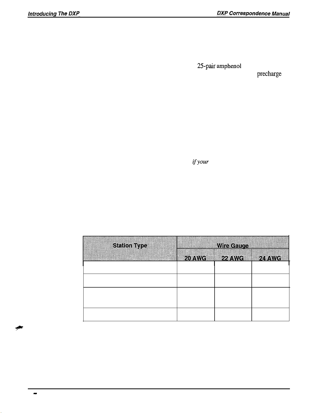
The following chart details the wiring requirements for all of the
different stations.
Digital Telephone
Analog Multiline Telephone
Analog Single-Line Proprietary
Telephone
Industry-Standard Telephone
Wiring The Stations
2500
Feet
2500
Feet
4000 Feet
4000 Feet
2000
2000
3500
3500
Feet
Feet
1500
1500
Feet
Feet
Feet 3000 Feet
Feet 3000 Feet
1 - 10 introducing The DXP
Page 23

DXP Correspondence Manual
Introducing The DXP
1.9
Identifying
The Line Boards
Line boards provide the interface for connecting the central office, or
CO, lines to the DXP. You can use a station board in Universal slots 1
through 5 in the main cabinet, universal slots 6 through 11 in the
expansion cabinet, and line slots 1 through 4 in the main cabinet (you
can only install a Tl board in the second line slot or the fifth universal
slot of the main cabinet, or in universal slot 8 or 12 in the expansion
cabinet). While line boards are optional, it’s rare that you will have an
application that won’t require CO lines. The DXP supports several
different types of line boards,
l Loop start,
l Multipurpose,
l Direct Inward Dialing, or DID,
l and
Tl.
Make sure that the lines coming from the CO match the line boards
that you install in the DXP. Having a Tl board does not mean you
have Tl lines, for example. Be sure to coordinate with your CO before
you plan your line configurations. Special software may be required to
support certain line boards. Your class instructor will give you further
details on software requirements when you take the classroom portion
of the training.
Like the station boards, each line board has a pre-power jack that
allows a technician to service the board while the DXP still has AC
power.
The status light on each line board indicates when a line is in use: off
with a five-second blink rate on indicates that all lines are idle; on
with a five-second blink rate off indicates at least one busy line. A
rapid flash indicates a malfunctioning microprocessor on the line
board. All line boards provide secondary surge protection; Chapter
Three discusses secondary and primary surge protection.
Introducing The DXP 1 - 11
Page 24

Introducing The
DXP
DXP Correspondence Manual
Line Boards-Loop-start Line Board
The loop-start line board (DXPCO-LP8, LP4) supports loop start
lines, and it is available in either a four- or eight-port capacity. Each
loop-start line board has modular jacks that provide connections for
either four or eight lines. You can connect an industry-standard
telephone to the bottom jack to serve as a power-failure telephone. If
the DXP should lose power, the power-fail telephone will continue to
operate. The LED on the front of the board indicates when a line is in
use: off with a five-second blink rate on indicates that all lines are
idle; on with a five-second blink rate off indicates at least one busy
line. A rapid flash indicates a malfunctioning microprocessor on the
line board. Each loop-start board also has a power fail and auxiliary
interface. For more information on the loop start board, see
IMI66-085.
Line Boards-Multipurpose Line Board
The multipurpose line board
lines, ground start lines, or E and M tie lines. Like the loop start board,
the multipurpose board also is available in either a four- or eight-port
capacity, and you can use any combination of the three line types.
However, ports three and four on each multipurpose board are the
only ports that support E and M tie lines. The LED on the front of the
multipurpose board functions exactly like that on the loop start board;
each multipurpose board also has a power fail and auxiliary interface.
For more information on the multipurpose board, see
(DXPCO-GDS,
GD4) supports loop start
IMI89-097.
I-
12 introducing The DXP
Page 25

DXP Correspondence Manual
introducing The DXP
Line Boards-T1 Board
The Tl board
(DXPTl)
provides 8, 16, or 24 channels of voice
transmissions over a single four-wire cable using multiplexing
techniques. You can install a maximum of four Tl boards, two in each
cabinet, but you can only install a Tl board in the second line slot or
the fifth universal slot of the main cabinet, or in universal slot 8 or 12
in the expansion cabinet. You can configure the Tl board with a
combination of loopstart, ground start, DID, and E & M Tie lines.
When you take the DXP classroom training, you’ll get a more
in-depth overview of the Tl board. For more information on the
board, see
IMI89-141.
Tl
Line Boards-DID Board
The DID board (DXPCO-DD8, DD4) lets, stations have their own
telephone number without having a separate line dedicated to that
station. The basic idea of DID is this: the central office sends digits to
the DXP, which interprets the digits and routes the call to the
appropriate station. For example, you can have fifty stations and only
ten DID lines, and each station can still have its own published
telephone number. However, only ten of the stations can be on calls at
one time. DID lines are incoming only, so if you need outward dialing,
you’ll need more than just DID lines. Like Tl , DID will be covered
more deeply in the classroom portion of this training. For more
information on the DID board, see
IMI89-103.
introducing The DXP 1 - 13
Page 26
1.10
Using The
Auxiliary Board
and Add-On
Cards
The auxiliary board is an all-purpose “mother board” that
accommodates up to four smaller option cards. You can install two
auxiliary boards in the DXP, but you can only install them in the
Universal / Auxiliary slots of the main cabinet. The option
include the DTMF Tone card, DXOPT-TON, the communications
card, DXOPT-COM, and the Tl sync. card, DXOPT-SYN. These
cards mount onto the auxiliary board, much like the RAM and
software cards mount onto the CPU board.
While you can install a station, line, conference, or auxiliary board
into either universal / auxiliary slot (first two slots next to the CPU
board), we recommend that you try to leave at least one of these slots
for an auxiliary board, even if you don’t need an auxiliary board now,
you may want to expand the system later. Remember, these are the
only two slots in the entire system that will accept an auxiliary board.
Use the line slots and universal slots for line and station boards before
you use a universal / auxiliary slot.
car&
DTMF Tone Card
The DTMF tone card expands the
capability: without a tone card, only two industry-standard telephones
can dial out of the DXP simultaneously. Each DXOPT-TON card
provides four more IST dialing paths. So if you are going to have
several IST telephones, it’s a good idea to install a tone card to make
sure that more than two of them can dial-out simultaneously. You can
install four tone cards on each auxiliary board (see
Installation Instructions, for more information).
DXP’s
industry-standard dialing
lMI89-078,
IST
1 - 14 Introducing The DXP
Page 27
DXP Correspondence Manual
introducing The DXP
Communications Card
The auxiliary board also supports the communications card
(DXOPT-COM);
the DXP has two serial data ports on the CPU
.
board. Each communications card provides four additional serial data
ports; you may need these ports for additional PC Attendants or
printers, for example. Keep in mind that the two serial ports on the
CPU board are the only two true-high-speed ports. Depending upon
system traffic, the serial ports on the
comm.
card may not operate at a
true 9600 baud rate. You can install up to two corn-cards on each
auxiliary board, but you must install them on the bottom two slots of
the auxiliary board. For more information on the Corn. card, see
IMI89-124.
Synchronization Card
Finally, the DXOPT-SYN, or sync. card, adjusts the DXP Tl transmit
frequency to match the frequency received from the central office or
master DXP. You only need a sync. card if you are using the Tl
board, and you can only install one sync. card into the DXP. If your
Tl
board is connected to the C.O., you must have a sync. card. If you
have two
DXPs
connected together with the Tl configured as E & M
tie lines, only one DXP must have a sync. card. For more information
on the sync. card, see
IMI89-141.
Introducing The DXP I- 15
Page 28

Introducing The
DXP
DXP Correspondence Manual
1.11
Using
The Conference
Board
The DXP services board provides for a limited amount of
conferencing. If additional conferencing is required, you may need to
install a conference board (DXCNF). Each conference board provides
five additional three-way conferencing circuits. You can install a
conference board in any universal or universal / auxiliary slot, and you
can install multiple conference boards. For more information on the
Conference board, see
lMI66-085.
1.12
1
In trocfucing
The Expansion
Cabinet
1
The expansion cabinet is very similar in design and function to the
main cabinet. The main cabinet holds 12 boards, and the expansion
cabinet holds up to eight additional boards. As its name indicates, the
expansion cabinet simply increases the number of stations and lines
that you can have on the DXP system.
The far left of the cabinet houses the expansion-cabinet power supply;
this power supply is designed specifically for the expansion cabinet.
Chapter three discusses the power supply in more detail. The
backplane and card cage are very similar to those in the main cabinet.
This first slot holds the interface 2 board. The interface 2 board
connects to the interface 1 board to secure the integrity of the digital
signals between the two cabinets. You must have an interface 2 board
if you are going to use an expansion cabinet. The remaining slots in
the expansion cabinet, universal slots 6 - 12, each can hold either a
line, conference, or station board. You cannot use an auxiliary board
in the expansion cabinet. For more information on the expansion
cabinet, see
IMI66-086.
1 - 16 Introducing The DXP
Page 29

DXP Correspondence Manual
Introducing The DXP
1.13
Concluding
Chapter One
The DXP is comprised of a series of mandatory and optional
printed-wire boards: the power supply, CPU and Services boards are
mandatory for system operation, as are the Software and RAM cards.
The line boards, station boards, auxiliary boards, and conference
boards are optional depending upon your application.
Before you go any further in this series complete the study at the end
of this chapter. By now, you should have a general understanding of
the function and capabilities of the DXP hardware, printed-wire
boards, and expansion cabinet; if you aren’t secure in your knowledge
of any of these, rewind Tape One and watch it again; then reread
Chapter One.
Introducing The DXP 1 - 17
Page 30

Introducing The
DXP
DXP Correspondence Manual
Chapter One
Review
Questions
I
1.
What does the term “modular design” mean?
2.
If a client wants the maximum number of lines on his or her
system, the maximum number of lines is
maximum number of stations is
3.
If a client wants the maximum number of stations on his or her
system, the maximum number of lines is
maximum number of stations is
4.
The number of lines and stations on a DXP is dependent upon
what?
and the
and the
5.
The DXP main cabinet holds a maximum of 20 boards; True
or False?
6.
The DXP can use any modem that supports the correct baud
rates; True or False?
7.
How long will a DXP battery backup provide operation to the
DXP in the event of a power failure?
8.
Is the interface board ever mandatory? If so, when? If not, why
not?
9.
What is the maximum number of Interface boards that you can
install in a system?
1 - 18 introducing The DXP
Page 31

10. The interface board for the main cabinet is interchangeable
with the expansion cabinet interface board; True or False?
.
11. What are the three uses for the six-pin jack on the Services
board?
12. What does it mean if the light on the Services board goes off?
13. How many serial data ports are there on the CPU board?
14. Which of the following is not housed on the CPU board:
Primary processing and control circuits
Master Timing
Interface connector for system memory
Primary system memory
Conferencing circuitry
System calendar and clock.
15. Where does the software card mount in the DXP?
16. What is the difference between the standard RAM and the
expanded
IV&I?
17. What are the three types of station board?
18. If a station board’s LED is steady-off with a five-second blink
rate, the board has a microprocessor problem; true or false?
introducing The DXP I- 79
Page 32

19. Station boards have a
cable for connection to the
station wiring.
.
20. What are the four types of line boards that the DXP supports?
2 1. Each DXP line board provides surge protection.
22. Where is the connection for a power fail telephone located?
23. DID lines are outgoing only; true or false?
24. The Tl board provides support for E & M Tie lines and ground
start lines; true or false?
25. You can install two Auxiliary boards in the DXP, and you can
install them in any universal slot; true or false?
26. What purpose does the
27. Each communications card provides
28. You only need a sync. card if you are using
DTMF
tone card serve?
?
?
I - 20 Introducing The DXP
Page 33

DXP Correspondence Manual
Introducing The DXP
29. The expansion cabinet needs its own power supply; true or
false?
30. The expansion cabinet holds a maximum of
boards
(excluding the interface 2 board)?
3 1. In Part One of the DXP video series, what is the narrator’s
name?
Introducing The DXP 1 - 21
Page 34

DXP Correspondence Manual
Chapter Con tents
Planning An Installation
Chapter Two: Planning An Installation
2.1
2.2
2.3
2.4
2.5
2.6
2.7
2.8
2.9
Introducing Chapter Two
Ordering
Evaluating The Installation Site
Planning The Dedicated Equipment Room ......................................... .2-3
Using The Right Tools
Preparing An MDF Diagram ................................................................
Checking The Hardware
Testing The Stations
Concluding Chapter Two
Chapter Two Review Questions
The Right Equipment ........................................................... .2-2
..................................................................... 2-l
...........................................................
.........................................................................
.......................................................................
.............................................................................
....................................................................
...........................................................
. . . . . . . . . . . . . . . . . . . . . . . . . . . . . . . . . . . . . . . . . . . . . . . . .
2-1
2-3
2-4
2-5
2-6
2-8
2-8
2-9
Chapter Con tents
Page 35

I I
2
L.
Planning An Installation
2.1
Introducing
Chapter Two
I
One of your primary responsibilities as the DXP installer is to
determine the type and quantity of equipment needed for each
installation site. Remember that the needs and specifications of each
installation site will be different based on the number of lines, stations
and peripheral equipment that fits that customer’s business. When you
begin a new installation, ask yourself some of the following questions:
l What are the client’s present and future telecommunications
needs? Are you replacing an existing business telephone system,
or is this a completely new installation?
l What are the problems the client is experiencing with his or her
old telephone system? Why is a DXP the right telephone system?
l How many lines and stations are you going to use? Remember to
leave plenty of room for future expansion.
l Will you use ground start, loop start,
l Will you have digital, analog, or IST stations?
l What peripheral equipment will you use: paging device, music
source, or battery backup, for example.
Tl,
or DID lines?
You’ll have to answer all of these questions well in advance of
actually ordering any of the equipment for you installation. Keep in
mind that your customers aren’t going to know whether they need
DID or ground start lines, for example, so you will have to make those
decisions based on your understanding of the client’s needs.
Planning An Installation 2 -
1
Page 36

2.2
ordering
The Right
1
Equipment
In determining what equipment to order, keep the client’s long-range
plans in mind. Make sure that you can add lines or stations when the
time comes to do so.
I
Remember that the two auxiliary/universal slots are the only slots that
accommodate Auxiliary boards. If you install a line or station board in
these slots, there will be no room for Auxiliary boards when the client
needs them. If at all possible, reserve at least one of the
auxiliary/universal slots for an Auxiliary board, and put the station and
line boards in the universal and line slots respectively.
For assistance in choosing the right boards, consult Comdial
publication
DXP Software Request Form. Both of these publications are in the
DXP System Manual. You can find the product codes for DXP parts
on the last page of
You may also want to purchase another Comdial videotape series
entitled “How to Sell Business Telephone Systems (V-l OC), ” which
provides not only marketing and programming tips but also gives
practical examples of the types of questions to ask a client.
GCA40-070
GCA40-112
“Configuration and Planning.” Also see the
“DXP General Description.”
.
2 - 2 Planning An Installation
Page 37

2.3
Evaluating
The
Installation Site
An important part of your pre-installation work is to map-out the
geography of the site. If you can, get up-to-date blueprints of the
building. If blueprints are unavailable, draw up your own rough floor
plans and cross sections of the building.
Make sure that at a minimum you have all of the following
information:
l The location of the equipment room.
l The anticipated location of all of the various telephones.
l The current location of the cable runs for pre-existing CO lines
and phone sets.
- I
2.4
Planning The
Dedicated
Equipment
Room
Comdial recommends that you use a dedicated equipment room for
the DXP installation. If you do have other equipment in the room,
make sure you check for radio frequency interference. If you aren’t
going to use an equipment room, make sure to install the DXP in a
low-traffic area where the equipment and wiring won’t be bumped or
knocked loose.
Keep in mind that the distance between the main cabinet and the
Telco/PBX
distance of 7 feet).
You must also install the equipment in an area whose temperature
stays between 32 and 122 degrees fahrenheit with less than 90 percent
non-condensing humidity.
An important element to the equipment room is the AC power;
hopefully, your equipment room has accessible outlets, if not, make
sure to have a professional electrician install one. The DXP requires a
dedicated
sure that the outlet is within four feet of where we mount the DXP so
that the power cord reaches.
(For more on this, read
must be 25 feet or less (Comdial recommends a nominal
117V
AC 15 AMP circuit for installation. We need to make
GCA40-112,
DXP General Description)
Planning An Ins talla tion 2 - 3
Page 38

2.5
Using The Right
Tools
Before you begin your system layout, you need to make sure that you
have all the right tools for a proper installation. Most of you have
installed telephone systems before, so none of this information is new
to you. In truth, you’ll probably have a standard list much longer than
the one we provide. Use these items as an essentials list, a bare
minimum of what you should have to install a system. You’ll need the
following:
l fasteners, either wood screws or toggle bolts, to attach the
common equipment to the backboard,
.
a screwdriver to match the wood screws,
.
an electric drill,
l punch-down tool for fastening wires to a type-66 block,
l crimping tool for 623-type modular plugs,
l 3-prong AC circuit tester,
l
#
10 or 12 gauge insulated, solid-copper wire for grounding the
system,
.
all associated surge protection-AC, line, and serial,
l a connectorized female 25-pair cable (at least ten feet long) for
each station and line board (note that loop-start line boards use
modular jacks for line connections)
This list is a minimum of what you’ll need. Your own experience will
guide you in selecting what is necessary.
2 - 4 Planning An Installation
Page 39

DXP Correspondence Manual
Planning An lnstalla tion
2.6
Preparing
An
MDF Diagram
~ Begin the layout plan by determining where each piece of equipment
will mount on the Main Distribution Frame (MDF). Standard
plywood usually works well as the main distribution frame. Using an
~ MDF helps us in several ways: it provides stability for the
~ system-many office walls are drywall, and the MDF helps ensure
that your moorings won’t slip or shift in the drywall; the MDF also
, isolates the system from the wall, keeping condensation off the
equipment; lastly, the MDF makes moving the equipment relatively
pain-free.
In planning
various cable runs in detail and consider where you should position
the following devices:
-
-
-
-
-
the
layout of the MDF, you should diagram all of your
the main cabinet
the expansion cabinet,
the surge protector(s),
the ground cables,
station blocks,
-
a modem,
-
the battery backup
-
an OPX-X,
-
a VMI-X,
-
an
ATI-D-
1 PT,
3/4-inch
-
line blocks,
-
the music source,
-
a paging amplifier,
Even if you are not installing these devices, allocate space for them on
the MDF because they may be installed later.
As far as the location of the DXP on the board, you will want to put it
in the left-hand comer since all of the wiring comes out on the right
side of the cabinet. If you are going to mount the battery backup on
the left, be sure to leave adequate room. Whether you are using an
expansion cabinet or not, you should leave enough room on the MDF
for both cabinets. The expansion cabinet always mounts above the
main cabinet. The cabinets have to be no more than two inches apart
to allow the cables from the interface boards to connect.
Make sure all of your cable runs are as short as possible. When you
wire your stations, remember that the length from the DXP to the
stations depends upon the type of station and the gauge of wire (see
section 1.8 in this manual for more information). You also want to
keep the wires as far away from fluorescent lighting as possible. If you
do have to cross these lights, run the wires perpendicular to the lights
in order to keep interference negligible.
-
and finally, the cabling
and wiring
requirements.
I
For more on DXP specifications, see
Description.
”
GCA40-112, “DXP
Planning An lnstalla tion 2 - 5
General
Page 40

2.7
Checking The
Hardware
It’s a good idea to check all of your hardware thoroughly before you
get to your installation site. Unpack all of the equipment and make
sure that there has been no damage during shipping; then test each
piece individually to make sure it operates correctly. Use the .
following list as a general guideline for pre-installation testing.
-
Check the power supply voltages of both the main cabinet and
expansion cabinet’s power supply. Refer to
correct power supply voltages.
-
Once you know that the power supply voltages are correct,
slide the power supply into its location and plug it in. You can
now begin installing and testing your boards. All of the boards
are shipped in static-safe bags. Make sure you are in a
static-safe area and wearing a static-discharge wrist strap
before you handle any of the boards or cards.
-
Visually inspect each board when you take it out of the box to
make sure there are no visible defects and to make sure you
have the correct board.
IMI66-085
for the
-
Begin testing with the CPU and Services board (the RAM and
software cards must be installed). When testing the CPU
board, make sure that DIP switch 8 is in the “on” position.
With both boards inserted and seated properly, turn on the
power supply and watch the LED on each board: Remember
that many of the boards have a different LED flash rate to
indicate proper operation.
Read Section One of this manual for LED light indications. It’s
a good idea to test all of the boards in the actual slots where
they will be installed, if for no other reason than to make sure
you have planned the configuration accurately. By testing all
of the boards, you also make sure that each of the
is fully functional.
DXP’s
slots
2 - 6 Planning An Installation
Page 41

-
If you do have a board malfunction, turn the power back off
and re-seat the board; if you didn’t insert the mounting screws,
do so. Power the system back up and check the boards again. If
you still have a malfunction, try inserting a different CPU or
services board; if the other board works, you know there is a
problem with your original board. Should you experience any
of these malfunctions, contact your Comdial technical-services
representative for more troubleshooting tips and technical
support.
Always remember to turn the power off before you insert the
-
next board to prevent damaging the boards. Some of the
boards, the station and line boards specifically, have pre-power
jacks that allow you to work with the power on. Other boards,
like the AUX. board, require that you have the power off
before doing any work. It’s a good idea to turn the power off
just in case.
Planning An installation 2 - 7
Page 42

Planning An Ins talla tion
DXP Correspondence Manual
2.8
Testing The
Stations
2.9
Concluding
Chapter Two
With your station boards installed, do a quick check on the digital
stations themselves. Plug each station into a station port and then use a
digital armiger (you can purchase these from any supply house). Plug
the
armiger
telephone that you know is operable. Then unpack each of the
telephones and test them on one of the station ports. Testing the
boards one-by-one this way not only guarantees that all of our
equipment works as it should, but it also makes it immediately
obvious which board is the problem should a malfunction arise.
Plus, you’ll know all of this information well in advance of your
installation date.
This section of the training series has given you a foundation for
planning and evaluating your installation site. If you are unsure about
any of this information, rewind tape two, Planning an Installation, and
reread this section of the manual.
into the board and test each port on the board
with-a
2 - 8 Planning An Installation
Page 43

DXP Correspondence Manual
Planning An installation
Chapter Two
Review
Questions
1.
In evaluating the DXP installation site, what are three things
that you should always consider before you begin a new
installation?
2.
In planning for an installation, you must also consider
peripherals such as (name four).
3.
In considering what components you need to order for the
system:
The number of telephones will determine how many
The type of telephones will determine whether you use
,
or
The number of lines will determine how many
The total number and type of boards will determine whether
you will need
boards.
.
.
.
,
4.
When you are installing the boards, always place the first two
station boards in the auxiliary/universal slots to allow for
future expansion, true or false?
5.
What is the required temperature range of a dedicated
equipment room?
6.
The DXP requires a
7.
You need to make sure that the DXP is within 25 feet of the
outlet; true or false?
8.
Name five tools that Comdial recommends you to have for an
installation.
circuit for installation.
I
Planning An Ins talla tion 2 - 9
Page 44

9. MDF stands for
.
10. Give three reasons for putting your equipment on an MDF?
11. The cabinet should be located to the right of the AC power
source to minimize the cabling distances; true or false?
12. Before you connect the power for testing, you should always
perform a
?
13. What should you do if you have a board malfunction during
your testing?
14. What are the first two boards that you should install when
testing your system?
15. You should use a
to check your digital stations.
16. In the second video of the DXP training series, the narrator and
installer are putting a DXP in what type of business? What is
the business’s name?
17. Video Two introduces an installer and programmer; what is his
name?
2 - 10 Planning An Installation
Page 45

Installing The DXP
Chapter Three: Installing The DXP
3.1
3.2
3.3
3.4
3.5
3.6
3.7
Introducing Chapter Three
Mounting The Main Cabinet
Mounting The Expansion Cabinet
Grounding
Installing The Power Supply
Expansion Cabinet Power Supply.. .............................................
Connecting A Battery Backup
Installing The Boards
Board
Using The Pre-power jack
Services Board ............................................................................
CPU Board..
Interface Boards ...........................................................................
Station
Line Boards
Auxiliary
Conference
The System..
locations ............................................................................
.................................................................................
Boards.. ............................................................................
..................................................................................
Board.. ..........................................................................
Board
........................................................................
...................................................................
................................................................
.......................................................................
................................................................
...........................................................................
............................................................
. . . . . . . . . . . . . . . . . . . . . . . . . . . . . . . . . . . . . . . . . . . . . . . . . . . . . . . .
.......................................................
.3-5
..............................................................
3-7
3-7
.3-S
3-8
3-8
3-8
3-9
3-9
3-9
3-I
3-l
3-2
3-3
3-3
3-4
3-6
3-7
3.8
Connecting The Lines..
Surge Protection
........................................................................
.......................................................................
.3-10
3-10
Page 46

Chapter
Contents
DXP Correspondence Manual
3.9
3.10
3.11
3.12
3.13
3.14
3.15
3.16
3.17
Connecting The Stations .....................................................................
Station Wiring
Testing The Stations
............................................................................
...........................................................................
3-l 1
Connecting An External Paging Device ............................................
Connecting A Modem ........................................................................
Connecting A Music Source ...............................................................
Installing The Ring Generator ............................................................
Connecting The PC Attendant ............................................................
PC
Attendant Wire Rotation ......................................................
PC
Attendant line Connection.. ..................................................3-l 6
Connecting A Printer
..........................................................................
3-l 6
Concluding Chapter Three .................................................................
Chapter Three Review
Questions
.......................................................
3-11
3-12
3-13
3-14
3-15
3-15
3-16
3-17
3-18
3-19
.
Chapter Contents
Page 47

DXP Correspondence Manual
Installing The DXP
Installing The DXP
3.1
Introducing
Chapter Three
Installing a DXP is relatively quick and easy because by the time you
begin the installation you will have already done much of the
preliminary work. When you get to your installation site, you will
have gone through many of the most crucial steps:
-
selected the correct hardware,
-
chose the telephones and lines,
-
configured the equipment room,
-
and positioned the equipment on the MDF.
When you have completed this preliminary work and checked all of
the hardware to make sure that it operated properly, you are ready to
install the system. When you have finished with this section of the
training, you should be acquainted with all of the following:
-
hardware installation, including the cabinets, boards, modem,
and ring generator,
-
DXP power requirements,
-
station installation,
-
line and station wiring,
-
and finally, the peripheral equipment, including the paging
amplifier, external music source, SMDA printer, and PC
Attendant.
Installing The DXP 3 - 1
Page 48

Installing The
DXP
DXP Correspondence Manual
3.2
Mounting The
Main Cabinet
Comdial recommends that you mount both cabinets on a
main-distribution frame
begin mounting the equipment, decide upon the overall layout and
draw outlines of each piece of equipment on the backboard.
When you secure the backboard to the wall, make sure the screws go
through the studs in the wall and not just through the sheet rock or
wall covering. A fully-loaded DXP can weigh from 80 to 100 pounds,
so the stability of the mounting is crucial. Mounting the backboard to
the wall studs provides all the stability the DXP needs.
Remember to mount the cabinet on the left side of the MDF; all of the
wiring connections are on the right side of the main cabinet, so putting
the cabinet on the left keeps the wiring as short as possible.
-
The DXP main cabinet has six screw-mount openings. These
mounting holes are approximately 24.5 inches apart.
-
Insert the top two mounting screws into the backboard and
tighten them within approximately
surface. You may have to drill these holes ahead of time,
depending upon your mounting surface.
(3/4-inch
plywood works well). Before you
.
l/4-inch
of the mounting
-
Hang the cabinet on the top screws, sliding it down until it
hangs securely.
-
Then, insert and tighten the remaining four screws through the
mounting tabs located on the lower edge of the cabinet.
-
Finally, tighten all six screws until they are flush with the
DXP. The screws for the DXP itself only need to go through
the backboard to ensure stability.
-
If you are going to mount an expansion cabinet, remove the
access plates from the top of the main cabinet; this is where
you will run the connecting cables between the two cabinets.
3 - 2 Installing The DXP
Page 49

DXP Correspondence Manual Installing The DXP
3.3
Mounting The
Expansion
Cabinet
The installation of the expansion cabinet is basically identical to that
of the main cabinet. The mounting screws for the expansion cabinet
are 18
above the main cabinet-no exceptions. Remember that you need to
keep the two cabinets within two inches of one another to connect the
cable for the two interface boards. Once you have secured both
cabinets to the MDF, you need to ground them to an earth-ground (see
section
s/r6
inches apart. You must always install the expansion cabinet
3.4, Grounding The System).
Grounding
System
3.4
The
The DXP system has internal secondary surge protection on all line
ports, and in order for this protection to be effective, you must connect
the cabinets to a reliable earth ground such as a metal cold water pipe
or a building frame ground. The ground stud is located on the side of
the main cabinet. You can use # 10, or
for grounding.
Run the ground wire from the expansion cabinet down to the main
cabinet and finally to the earth ground. Ideally, the grounding wire
should be shorter than 20 feet. Grounding the system provides
secondary line surge protection, and AC surge protection; it also
serves as the ground for ground start, DID, and E and M tie lines. (For
information on primary surge protection devices, see Section 3.8,
Installing The Lines).
#12
gauge solid copper wire
Installing The DXP 3 - 3
Page 50

Installing The DXP
DXP Correspondence Manual
3.5
Installing The
Power Supply
The power supply for the
expansion cabinet (DXPSX) are shipped separately and require some
installation. During your initial preparation, you made sure that the
DXP cabinet would be mounted no further than four feet away-from a
dedicated
standard electrical outlet. To avoid power fluctuations caused by other
electrical appliances, it’s best not to install anything but the DXP
system on the outlet. Always use an AC surge protector to protect the
DXP from fluctuations in the AC power. Since the AC power cord is
only four feet long, make sure to mount the surge protector on the left
side of the main cabinet.
Also, to avoid an accidental power loss, make sure the outlet doesn’t
have a switch to turn off power. After you have chosen your dedicated
outlet, always do a voltage check on the outlet before you plug in the
system. To check the voltage using an AC Volt meter, first check the
voltage between the neutral and the “hot” side of the outlet; the
reading should be between 90 and 129 VAC. If the voltage range is
beyond this specification, contact a qualified electrician immediately.
117V
AC 15 AMP circuit, with a third-wire ground on a
DXP’s
main cabinet
(DXPSM)
and
-
The power supply slides into the slot on the left side of the
cabinet; it has two openings which slide over the two metal
posts on the front of the DXP cabinet.
-
Attach the two hex-nuts through the slots on the front of the
power supply and into the DXP cabinet.
-
Install the remaining screw in the back of the power supply
and into the cabinet. Route the power cord through the slot on
the side of the cabinet. (for more information on the main
cabinet power supply, see
-
Remember to connect the power to a surge protector and not
directly to an outlet.
IMI66-085.)
3 - 4 Installing The DXP
Page 51

DXP Correspondence Manual Installing The DXP
Expansion Cabinet Power Supply
The installation of the expansion cabinet power supply is virtually’
identical to that of the main cabinet power supply. One critical
difference between the two, however, is that there is an AC and DC
connection from the expansion cabinet’s power supply to the main
cabinet’s power supply (for more information on the expansion
cabinet power supply, see
DC connection from the expansion cabinet run through the access hole
on the bottom of the expansion cabinet and through the hole on the top
on the main cabinet. The AC cord then plugs into the three-pronged
outlet on the front of the main power supply; the DC power cable
connects to the S-pin male connectors on the main and expansion
cabinet’s power supplies.
You should have checked both of your power supply voltages earlier,
so now power-down and continue with your installation (see
IMI66-085
for information on testing the power supplies).
lMI66-086).
Both the power cord and the
Installing The DXP 3 - 5
Page 52

3.6
Connecting A
Battery Backup
The DXP works with the Comdial BBLDX. Should the AC power
fail, this main battery backup provides a minimum of one hour of
system operation on a 70% loaded system. To guarantee an hour with
an expansion cabinet, you need two battery backups. Comdial ‘has
created a formula whereby you can determine the battery backup time
for your system based on your number of lines and stations (see
IMI89-074).
manufacturer’s battery backup unit, if you determine that one UPS
won’t provide the backup time needed.
Note that a battery backup may take up to 12 hours to recharge after it
has been completely discharged. You may also need to wait 12 hours
after your initial installation before you have full battery backup
capabilities.
-
-
You can install an additional battery backup, or another
Remove the lid from the empty metal enclosure and save the
retaining hardware; you should mount the battery backup on
the left or below the main cabinet. Also leave room below the
battery backup to add another assembly in the future.
Once you have attached the assembly to the wall, slide the
batteries into their cabinet. You have to wire the five batteries
together in series with the supplied cable.
-
Now plug in the power cord. Always be sure that the AC
power cord is connected to the electrical outlet and the power
switch is in the “on” position before you connect the external
battery backup to the main cabinet. Having the power
connected ensures that the internal protection circuitry is
operating to prevent damage that could result from improper
connection.
-
Check the output voltage of the power supply before you
connect the batteries to the DXP power supply. The output
voltage should be between 34.3 and 34.6 volts; if it’s any
higher, the batteries could overcharge and be damaged. The
measured voltage should be between 27 and 35 volts (see
IMI89-074
-
Disconnect the power cable from the battery backup and
power-down before you move on with the installation. If you
leave the battery backup connected, you will be drawing power
from the battery during the rest of your installation.
for voltage test).
3 - 6 Installing The DXP
Page 53

DXP Correspondence Manual
Installing The DXP
3.7
Ins falling
The
Boards
As part of your pre-installation work, you will have made sure that all
of your boards were fully functional. So you can now go ahead and
start installing them.
When you work with any of the boards, always wear a static discharge
wrist strap and work in a static-safe work area. Do not remove the
board from its static-protected bag until you are in a static-safe area
(for information on electro-static discharge, see
of Electrostatically Sensitive Components). When installing any board
into the DXP, push only on the tabs on the outer edges of the board.
IMIO1-005,
.
Handling
Board Locations
Labels appear under each slot on the front edge of the cabinets,
indicating which board should go in the slot, and the boards are
mechanically keyed to fit only in the correct slots.
When inserting circuit boards, orient them so that they line up with the
top and bottom guides on the card cage. Keep in mind that the boards
fit snugly into the slots. Slide the boards into the card cage until the
connector on the back edge of the board properly mates with the
connector on the backplane.
If you suddenly encounter resistance while inserting a board into the
card cage, do not try to force the board into place.
Keep in mind that Universal/Auxiliary 1 and Universal/Auxiliary 2 are
the only two slots in the entire system, including the expansion
cabinet, that hold an auxiliary board.
Using The Pre-power jack
The services, CPU, and auxiliary boards all have to be installed with
the power off; line and station boards have pre-power jacks that allow
you to install them while the system still has power. The pre-power
jack is typically for when you are adding board into an existing system
and you don’t want to disturb the customer’s service. If you’re
installing a new system, there’s no need to keep the power on.
If you ever insert a station, line, or interface board while the DXP
system is on, make sure to prepower the board first to prevent a power
surge to the board or to the system. You must prepower the system
before the board makes contact with the backplane.
-
Use the standard telephone handset coil cord supplied with the
main cabinet and connect one end of the cord to the prepower
jack on the main cabinet’s power supply unit and the other end
to the prepower jack on the board. Simply making the
connection prepowers the board. The LED on the board will
flash to indicate that the board has been pre-powered.
Installing The DXP 3 - 7
Page 54

installing The
DXP
DXP Correspondence Manual
Services Board
The second slot in the main cabinet if reserved for the
You must have the power off to install the services board.
services‘board.
CPU Board
Remember that the CPU board consists of the RAM and Software
cards. Use the supplied # 4 machine screws to connect the
to the CPU board. The RAM card is connected to the CPU board by
using the supplied screws and washers. A 64-pin DIN connector
connects the CPU board to the RAM card.
The Software card is connected to the RAM card with the supplied
lockwashers and machine screws. Signals pass between the RAM card
and the Software card through a 64-pin, dual, in-line connector.
Once you have attached the RAM and Software cards to the CPU
board, insert the entire assembly into the correct slot in
Make sure DIP switch 8 is in the “on” position. Then power up the
system and check the status light on the CPU board. If it lights without
flashing, power off and move on.
ILAM
the
card cage.
card
Interface Boards
The first slot in the cabinet, moving from left to right, is for the
Interface 1 board (DXINM). The interface 1 board buffers the signals
sent from the main cabinet to the expansion cabinet. The expansion
cabinet interface board
expansion cabinet. The slot for the interface 1 board is smaller than
any of the other card-cage slots. The interface board is the only
half-sized board that inserts directly into the backplane. The interface
boards are connected with a 64-pin ribbon cable.
(DXINX)
mounts in the first slot in the
Station Boards
You can install a station board in any universal slot in either cabinet.
The DXP automatically numbers stations according to the station
board location; the number designations move from left to right, and
from the main cabinet to the expansion cabinet.
Each station board uses either one or two
connectors to go from the station board to the station punch-down
block. Each station board has a pre-power jack that allows a technician
to service the board while the systemstill has AC power on. (for more
information on the Station boards, see
25pair amphenol
IMI66-085.)
3 - 8 Installing The DXP
Page 55

DXP Correspondence Manual Installing The DXP
Line Boards
You can install a line board in any universal slot or in the four.
dedicated line slots; note that Unlike the station board designations,
the line slots are numbered from right to left. Each line board also has
a pre-power jack that allows a technician to service the board while
the system still has AC power on. The connection of the line board
depends upon the type of line board (for information on the wiring of
line boards, see
IMI66-085).
Auxiliary Board
You can install two auxiliary boards in the DXP, but you can
install them in the two Universal / Auxiliary slots of the main cabinet.
The option cards include the
communications card, DXOPT-COM, and the Tl sync. card,
DXOPT-SYN. You can only install the DXOPT-COM card on the
lower two slots of the auxiliary board. These cards mount onto the
auxiliary board, much like the RAM and software cards mount onto
the CPU board.
DTMP
Tone card, DXOPT-TON, the
only
Conference Board
You can install a conference board (DXCNF) in any universal or
universal / auxiliary slot, and you can install multiple conference
boards. The conference board also has a pre-power jack that allows a
technician to service the board while the system still has AC power on
(for more information on the Conference board, see
IMI66-085).
Installing The DXP 3 - 9
Page 56

3.8
Connecting The
Lines
.I
1
When you do any work with telephone lines, always adhere to the
following safety guidelines:
-
Never install telephone wiring during a lightning storm.
-
Never install telephone jacks in a wet location unless the jack
is specifically designed for wet locations.
-
Never touch uninsulated telephone wires or terminals unless
the telephone line has been disconnected at the network
interface.
-
Use caution when installing or modifying telephone lines.
The telephone company’s “demarcation block,” commonly referred to
as the
individual 4-position modular jacks. You must place your own
specialized 66-block next to the demarcation block and connect them
with # 24 gauge wire. Before you run line cables to the cabinet, use a
telephone test-set to check each CO line for a dial tone.
Always take thorough notes about line locations and types; you will
need all of this information later when you connect your peripheral
equipment and program your lines and line groups. Good records are
essential too if we need to come back later and make line changes or
move lines.
RJ21X,
is usually a 66-type connector block or a series of
Surge Protection
The telephone company usually offers a basic protection against the
possibility of transient voltage spikes traveling through the lines, but
that protection usually only guards the CO circuits and not the DXP.
In order to fully protect your lines, install and properly ground
primary surge protection on all lines. Comdial recommends that you
use gas-discharge tubes, but any similar line-protection device will
suffice. Once all of the lines are connected from the demarcation
blocks to the 66 blocks, it’s a good idea to mount another series of
66-blocks; these blocks will connect directly to the
multipurpose line boards. Having the connections to the DXP and to
the demarcation blocks separated by another 66-block allows you to
move the lines easily without having to alter the wiring scheme from
the CO or to the DXP.
IMI66-085
shows the connections in relation to the 25-pair
When you are wiring your lines, keep in mind that ground start lines
are polarity sensitive.
provides a diagram illustrating the line connections; it
DXP’s
amphenol
connector.
3 - 10 Installing
The
DXP
Page 57

3.9
Connecting The
Stations
1 Station connections, like line connections, are typically through
~ boards, are also connected through
While the station boards have protection against shorts, it’s better to
~ punch down the wiring with the power off.
66M-xx
Both IST devices and digital stations are two-wire connections, but
you should skip space on the IST block to avoid crosstalk. With digital
signals, crosstalk isn’t a problem. The polarity on the wires isn’t
important for either the digital or IST stations.
If your station cables must cross over fluorescent lights, the cables
should cross the lights at a
the magnetic field that builds up around the lights. You should also
make sure that the wires are elevated at least two feet above the light.
If the telephone wire runs near a light that is fluttering, you may
encounter some interference, so make sure any such light is replaced
before you continue.
connector blocks. The station boards, like many of the line
25pair
go-degree
male
amphenol
angle to diminish the effect of
connectors.
Station Wiring
Use the same approach to station connections as you did with your
lines; connect each station board to a 66-block, again using both sides
of the block. Then cross connect that 66-block to another 66-block
that will be connected to the house wiring. This dual connection
makes moving any of your stations much easier since you don’t have
to change any of the wiring to the station boards or to the house
wiring. If you are running any station wire outside the building, be
sure to provide extra surge protection on the station cables.
The maximum total distance allowed from the common equipment to
the stations is 1500 feet for multiline telephones, using # 24 gauge
twisted pair cable, and 3000 feet for industry standard telephones
using # 24 gauge, twisted pair cable (see section 1.8 of this manual for
more cabling information). If you have any spare conductors on the
cables between the 66-blocks and the station jacks, it is a good
practice to connect them to earth ground to help prevent them from
inducing radio frequency and / or AC interference into the system.
lnstaiiing The DXP 3 - 7
1
Page 58

Installing The
DXP
DXP Correspondence Manual
3.10
Testing The
Stations
Power up the DXP and take a voltage measurement across each signal
pair on the type-66 station block. The appropriate voltage
measurements are also shown on charts in
To test the stations, plug in the digital station and check to see that the
LCD appears (if applicable). Once the LCD comes up, perform a
station self-test:
-
unplug the telephone,
-
press and hold the 1 key as you plug the telephone back in
(mute key on analog, such as
-
If all of the
station is working.
-
Finally, seize an intercom line and make a call. Complete the
call to make sure that you have two-way communication.
Make sure that any Scout
fully charged before you place them in service. Also check your
industry-standard telephones. Plug the station in, and make sure
you hear a dialtone. Make sure that the IST stations ring when called,
to ensure that the ring generator is working properly.
LEDs
light in sequence and the telephone rings, the
9OOMX
digital wireless telephones are all
IMI66-085.
ExecuTech,
telephones).
that
3 - 12 Installing The DXP
Page 59

3.11
Connecting An
External Paging
Device
You can connect a paging device either to the paging port on the
Services board or to a line port. The line port can be used to couple a
station’s voice path to an external paging device. Any station with the
line appearance can use the PA system by selecting the line; IST
stations can use the amplifier by dialing a line-group access code.
When the paging device is connected to a line port, users can speak
through or dial DTMF tones or pulses to the external device through
the PA device, depending upon the type of paging device.
Connect the voice pair (tip and ring) leads of the line dedicated as an
auxiliary port to the audio input of an external paging amplifier. You
will have to program the line as an auxiliary line in programming.
Make sure to consult the installation manual of the paging device for
any requirements or specifications beyond those of the DXP.
installing The DXP 3 - 13
Page 60

installing The DXP DXP Correspondence Manual
3.12
Connecting A
Modem
The DXP has its own proprietary modem, product number DXMDM,
so installation is simple. You can use a non-proprietary modem, but
using the modem designed for the DXP is a good idea. The modem
installs next to the power supply in the main cabinet. All that’s
involved in the hardware connection is attaching the mounting screw
to the card cage. The top jack on the modem is for the line cord, and
the bottom jack is for the serial data connection. You can connect the
modem to any available serial data port on DXP. The power cord from
the modem attaches to the
set the Dip switch 7 to the ON position because the modem depends
upon the DXP for its power and configuration, and with switch 7 on,
the system automatically sends the initialization string to the modem
in case of a power failure or system reboot.
precharge
port on the power supply. We’ll
3 - 14 Installing The DXP
Page 61

DXP Correspondence Manual Installing The DXP
3.13
Connecting A
Music Source
You can connect a maximum of two customer-supplied music sources
to the DXP to provide background music and music on hold. The
music sources connect to the jack on the services board. The input
impedance of the music interface is approximately 500 ohms. You can
create a special announcement on hold for outside callers. Remember
that it’s illegal to use a radio station as your music-on-hold.
3.14
Installing The
Ring Generator
The ring generator
waiting voltage to the industry standard devices. Remember that you
need a ring generator in each cabinet that has an IST board. The ring
generator mounts directly above the power supply in either cabinet,
and it plugs into the backplane. You must have a ring generator in
each cabinet that you use industry standard telephone boards.
(DXRNG)
provides ringing voltage and message
Page 62

3.15
Connecting The
PC Attendant
The PC Attendant requires two loop-start line ports, one serial data
port, and one logical station port. Connect the two line ports for audio
connection to the DXP, one for transmit and one for receive, and the
serial data port for the data communication. You don’t need
the station port, but we do have to assign it to the PC Attendant in
programming. Having a station port assigned provides a logical port to
use for programming station features on the PC Attendant.
We’ll start with the serial connection from the serial data port on the
DXP to a standard 6-conductor modular jack. When connecting the
serial data port, keep in mind that you must to have an odd number of
wire rotations to ensure that the roll-over in a standard line cord
remains intact.
to-wire
PC Attendant Wire Rotation
Connect the data port on the DXP to a 6-conductor modular jack using
a standard 6-conductor line cord; Comdial recommends 3-pair,
twisted, shielded, 24-gauge wire from this modular jack to the PC
Attendant’s location. The wires are color coded, and at the DXP end
you should keep the colors consistent, wiring red to red, green to
green, and so on. At the PC Attendant location, install another
6-conductor modular jack. Bring the wires from the first modular jack
and connect them the the modular jack at the PC Attendant location,
but rotate the color coded connections: red to green, green to red, and
so on. Now connect the
Attendant to this modular jack with a 6-conductor line cord and your
connection is complete. Because you have rolled our house wiring, the
transmit data now connects with your receive data. Keep in mind that
the connection between the PC Attendant and the DXP must be 500
feet or less.
g-pin
connector supplied with the PC
PC Attendant Line Connection
The PC Attendant line connection is just like any other line
connection. For the PC Attendant you need to use Loop-start lines.
You also need to make sure that the lines are paired; 1 and 2, or 3 and
4, for example. With all of your wiring done, check the PC Attendant
to see if you have communication.
The
DXP’s
the peripheral equipment, like the PC Attendant, so you might want to
purchase a secondary uninterrupted power supply, which would also
provide AC surge protection. Should there be a power-outage, the PC
Attendant will still be able to process all of the calls for the facility.
battery backup does not provide backup power to any of
Page 63

DXP Correspondence Manual Installing The DXP
3.16
Connecting A
Printer
You can connect a serial-data printer for SMDA records. You can
connect the printer to any serial data port on the DXP, but serial data
port two is defaulted for a printer. If your printer is not near the DXP,
~ you must put one modular jack on the wall next to the DXP and
another next to the printer. Wire these two together with 24-gauge,
shielded wire, making sure to rotate the wires. The printer only
requires the transmit data and signal ground wires. The handshaking
connection usually isn’t necessary unless you are running at more than
2400 baud. Check your printer manual for printer baud rate
information. You’ll have to provide your own
printer.
25pin
connector for the
Installing The DXP 3 - 17
Page 64

3.17
Concluding
Chapter Three
That concludes the installation section of the training. Before you
move on to programming chapter, complete the questions on
installation. If you are unsure about any of the installation procedures,
review part three of the training series, Installing the DXP, and rei-ead
this chapter. When you’ve finished, you’ll be ready to move on to
Chapter Four,
Programming the System.
Page 65

DXP Correspondence Manual Installing The DXP
Chapter Three
Review
Questions
1. A fully loaded DXP can weigh as much as
2. The DXP main cabinet has
which are approximately
3. How much space can you leave between the expansion cabinet
and the main cabinet? Why?
4. You can install the expansion cabinet above or to the left of the
main cabinet; true or false?
5. The grounding wire should be
length of less than
screw-mount openings,
inches apart.
wire with a maximum
.
6. The power supply requires a dedicated
7. You don’t need to use an AC surge protector unless you have
an expansion cabinet; true or false?
8. You only need to check the voltage on the main cabinet power
supply unit, true or false?
9. How is the expansion cabinet power supply different from that
of the main cabinet?
10. Always mount the optional battery pack above the expansion
cabinet, true or false?
?
I
Installing The DXP 3 - 19
Page 66

11. What is the correct output voltage of the DXP power supply?
12. The BBLDX provides up to 12 hours of battery backup; true or
false?
13. Describe two measures you can take to prevent electrostatic
discharge damage to the boards.
14. The boards should be inserted with the power on, true or false?
15. What prevents you from inserting a board in the wrong slot?
16. What two things must you attach to the CPU board before you
install it?
17. The station ports and line ports are both numbered the same
way from left to right on the designation strip of the card cage;
true or false?
18. The interface boards are connected with
?
19. If you ever have to insert a station or line board when the
system is under power, you must
20. List two of the four Comdial safety guidelines for working
with telephone lines.
3 - 20 Installing The DXP
Page 67

DXP Correspondence Manual Installing The DXP
21. To prevent damage from transient-voltage spikes on line
jumper cables, you should install
22. When installing lines, it’s important to remember that ground
start lines are
23. Station connections are through
.
24. The polarity of digital station connections is essential; true or
false?
25. At the station block, you should tie unused station pairs to
ground, true or false?
26. You can install an external paging device on either the
Services or CPU board; true or false?
27. Which serial data port must you use to connect the modem?
28. Setting DIP switch 7 on the modem to “on” accomplishes
what?
29. The input impedance of the music interface is
approximately .
30. You only need one ring generator, no matter how many IST
stations you have; true or false?
I
Page 68

Installing The
DXP
DXP Correspondence Manual
3 1. Having a station port for the PC Attendant does what?
32. Explain what it means to “roll” the house wiring for the PC
Attendant.
33. The maximum distance between the DXP cabinet and the PC
Attendant is .
34. Which serial data port is defaulted for an
SMDALSMDR
printer?
35. In the DXP video series, does the installation use the Scout
9OOMX
digital wireless telephones?
36. How many men are shown installing the DXP in the video?
37. Why did the installation site in the video use an external
paging device?
3 - 22
Installing The DXP
Page 69

DXP Correspondence Manual
4
L
Chapter Con tents
Programming The DXP
Chapter Four: Programming The DXP
4.1
4.2
4.3
4.4
4.5
4.6
4.7
4.8
Introducing Programming
Using Other publications
Two ways to Program...........................................................................
Connecting Data Devices
Using A Modem ...................................................................................
Using The DXP Menus
Accessing the Main Menu
Understanding The Main Menu
Chapter Four Review Questions
....................................................................
......................................................................
.....................................................................
........................................................................
....................................................................
...........................................................
...........................................................
. . . . . . . . . . . . . . . . . . . . . . . . . . . . . ..*..................
4-1
4-l
4-2
4-3
4-4
4-5
4-6
4-7
4-8
4-9
Chapter Con tents
Page 70

DXP Correspondence Manual
Programming The DXP
Programming The DXP
4.1
Introducing
Programming
The DXP comes from the factory already programmed with certain
features. However, you will frequently have to alter or add on to these
“default” settings to maximize the
Master Clearing The System, and section 5.3, Setting The System
Defaults, for more information.) As the DXP installer and
programmer, you will be responsible for knowing all of the system’s
features and capabilities (for more information on the system features,
see
GCALCO-112,
This chapter discusses the basics of DXP programming, including the
data device connections and on-screen programming options. Use
IMI66-111,
continue through this correspondence manual.
DXP General Description).
the DXP programming manual, as a reference as you
DXP’s
capabilities (see section 5.2,
DXP Correspondence Manual 4 - 1
Page 71

4.2
Using Other
publications
Two Comdial publications can help you with DXP programming:
“Programming Records For The DXP Digital Communications
System, ”
closely follows the sequence and layout of the DXP’s programming
menus. Prior to programming, go through this document with the
client, explaining the
programming selections in the spaces provided.
“Video Display Terminal Programming Instructions, ” DXP Digital
Communications System,”
authorized DXP installers. This document allows you to avoid going
through the entire programming sequence from start to finish when
you want to modify certain features after initial programming. Using
this document, you can go directly to the feature you want to program.
The document includes a handy cross-reference chart that lists DXP
features alphabetically. Each entry includes a brief feature description
and the keyboard commands needed to program the feature.
NOTE: Be sure to carefully read each section of your
IMI66-088,
correspondence manual for references to other relevant
Comdial publications.
is shipped with each DXP. This document
DXP’s
various features, and record
IMI66-087,
is made available to
4 - 2 DXP Correspondence Manual
Page 72

DXP Correspondence Manual
Programming The DXP
4.3
Two ways to
Program
There are two distinctly different ways in which you can program the
DXP: directly through the DXP or through the database program
PCMMI.
The most common form of DXP programming is to directly connect a
PC, video display terminal (VDT), or dumb terminal to one of the
serial ports on the CPU board. Then, using PROCOMM Plus for
WindowsTM,
the default database in the DXP. With this direct connection, any
changes that you make in the DXP are immediately altered in the
database. You cannot save your programming choices to disk if you
are using a VDT or dumb terminal.
The second way to program the DXP is through the database creation
program called PCMMI (Personal Computer Man Machine Interface),
which allows you to make DXP database changes without being
connected to the DXP. When you have created the database, however,
you must then upload that information into the DXP through a serial
port using your communication software. PCMMI allows you the
flexibility to work with the database without having the DXP
hardware in front of you.
or some other communications software, you can change
.
While you cannot use a telephone set to fully program the DXP, you
can use a telephone to do some basic programming such as setting the
system clock and system speed dials (for more information see
GCA40-113).
For more information about VDT and PC programming and related
software, consult
Instructions, DXP Digital Communications System.
IMI66-087
Video Display Terminal Programming
DXP Correspondence Manual 4 - 3
Page 73

4.4
Connecting Data
Devices
The DXP has two serial data ports on its CPU board that
accommodate data devices such as
You can also add serial data ports with the communications card
(DXPCOM).
If the cable from the data device you want to use is not already
equipped with an
manufacturer’s manual. Also see,
connections. When connecting a data device, be sure to consider the
following information:
-
The DXP and the data device each have a transmit data lead, a
receive data lead and a signal ground. For a VDT, connect the
DXP’s receive data lead to the
connect the DXP’s transmit data lead to the
data lead and connect the DXP’s signal ground or SG lead to
the device’s SG lead.
-
If “handshaking” is necessary between the DXP and the data
device, connect the DXP CTS (clear to send) lead to the
appropriate lead of the data device. For more information
about these connections, consult IMI 66-085.
RS232-type
VDTs,
jack, refer to the data device
IMI66-085,
PCs, printers and modems.
for the proper wiring
VDT’s
transmit data lead and
VDT’s
.
receive
-
Data devices connected to the DXP should be configured to
operate compatibly with the DXP’s default setting of eight-bit
data with one stop bit and no parity at a baud rate of 9600
baud, for port one. Port two defaults to seven-bit data, two stop
bit, no parity and 300 baud.
Remember that the maximum distance between the DXP cabinet and
the data device should not exceed 500 feet unless short-haul modems
are used.
4 - 4 Programming The DXP
Page 74

4.5
Using A Modem
To program the DXP remotely through a VDT or PC, you must use a
pair of data modems. These modems can be any commercially
available, Hayes-compatible modems with auto-answer capability.
You should verify that the modems have auto-answer capability
before purchasing them. If the modems do not have auto-answer
capability, someone at the site must manually activate the on-site
modem.
When you install a modem, always consult the modem manufacturer’s
manual and check the configuration of the signal leads. If the
modem’s cable is not equipped with an RS232 jack compatible with
the
DXP’s
the proper connector.
To connect the modem to the DXP, run the modem’s cable between
the modem’s data jack and one of the DXP serial port; then connect
the modem to the outside telephone network in one of two ways:
-
serial data ports, you might have to rewire the cable with
Reserve a line exclusively for remote programming by
punching down the appropriate leads on the type-66 line block
and running a line cable directly to the network jack on the
modem.
.
-
Install a line switch for the modem between the type-66 line
block and the common equipment; the line will be available
for system users unless the switch is thrown, at which time the
remote programmer will have exclusive use of the line. Keep
in mind that using this method requires someone at
installation to turn the switch before remote programming can
begin.
To begin remote programming after you have installed the modems,
establish the data link between the modems by dialing the appropriate
phone number. Then program the DXP exactly as if your VDT or PC
were connected directly to the system.
the
Programming The DXP 4 - 5
Page 75

Programming The DXP
DXP Correspondence Manual
4.6
Using The DXP
Menus
The DXP is a menu-driven system, and many of the features are
located in sub-menus. Each menu may contain several sub-menus, and
it will take you some time to become familiar enough with the DXP
that you know where all of the features are located (see
DXP
General Description, for a full description of the DXP features).
-
To maneuver through the DXP menus, enter the number that
GCA4k1.12,
corresponds with that feature.
-
Since several of the sub-menus have multiple pages, you may
often have to use the
“CTF&3”
to move to the previous page. Also, some menus
“Cm-N”
to move to the next page and
give you questions as options; these questions are usually
self-explanatory and the commands are easy to understand.
To return to the previous menu, select the item on the menu
-
that allows you to do this or press ESCAPE. To return to the
main menu, press CTRL-T.
-
You must separate successive entries for a single item with a
space or a comma. However, entries should never end in a
comma. You can enter many entries by specifying a range; for
example, entering
lOl-
1.50 includes all entries between 101
and 150.
While you may not know exactly where in programming a feature is
located, you can probably find the feature simply by looking at the
DXP main menu. The DXP programming is divided into several broad
classifications; these main menu classifications allow you to do all of
your associated programming together -system, station, and line, for
example.
Since the system operates on a lo-minute time-out cycle, you must
enter a selection or response within this time. If you don’t enter a
response within 10 minutes, the programming sequence is aborted and
the message
“Logout
Programming” appears on the screen. This
automatic log-off function acts as a safeguard to prevent tampering by
unauthorized persons.
4 - 6 Programming The DXP
Page 76

DXP
Correspondence Manual Programming The DXP
4.7
Accessing the
Main Menu
I
f
1.
system
2.
Stations
3.
Lines
Intercom Numbers
4.
5.
SMDA/SMDR
The first menu that appears on the screen when programming the DXP
with a VDT or PC is called the “main menu.” To access the main
menu:
-
-
-
Power up the DXP and the VDT or PC.
Press ENTER to bring up the banner display.
Type in the programmer’s password code, I
%746+k,
.
and press
ENTER. The main menu appears with the following items (the
password isn’t required in PCMMI programming).
Main Menu
6.
To1
1
Printouts
7.
Diagnostics
8.
9.
Peripherals
10.
Logout
P63H
/AR3
CONT BRIGHT
LG
ON
FFF
HO
,
Programming The
DXP 4 - 7
Page 77

Programming The
DXP
DXP Correspondence Manual
4.8
Understanding
The Main Menu
The items on the main menu correspond to the major categories of the
DXP’s database. The first three items on the main menu represent the
following:
l System, involves features that affect the operation of every
telephone in the system. Some examples of features in this
category are system timing features like Unanswered Call Ring
Back, Recall/Flash, and Pause Time. System programming is
examined in detail in Chapter Five.
l Stations, involves features programmed for individual telephones.
These include button assignments and ringing assignments as well
as features like Do Not Disturb, Call Forwarding and Personalized
Ringing. Station programming is examined in greater detail in
Chapter Six.
l Line, involves features associated with the line ports that connect
the system to the lines from the outside world. This category
includes features such as Automatic Line Selection, Line
Grouping, and Line Restrictions. Line programming is examined
in detail in Chapter Seven.
In addition to these three main categories, the rest of the DXP
programming is divided into several other broad classifications, which
are as follows:
l Intercom Numbers.
.
SMDA/SMDR.
l Toll Restriction/Automatic Route Selection.
l Printouts.
l Diagnostics.
l Peripherals
l
Logout,
allows you to escape from the
DXP’s
database, and it
terminates the programming sequence. If you choose this option,
you will drop out of the programming mode, and the message
“Logout
Programming” will appear on the screen. Note that any
changes you have made in the PCMMI will be lost unless you save
them.
4 - 8 Programming The DXP
Page 78

DXP Correspondence Manual
Programming The DXP
Chapter Four
Review
Questions
I
1. What two Comdial documents can assist you when you are
doing your DXP programming?
.
2. How does programming the DXP directly from a VDT or PC
differ from programming through the PCMMI?
3. You can program the DXP entirely with a telephone, as long as
it is an LCD speakerphone; true or false?
4. The DXP supports a maximum of two serial data ports; true or
false?
5. List the default values of the two serial data ports on the CPU.
6. The maximum distance between any data device and the DXP
is
7. Describe the two fundamental ways to connect a modem.
8. What do the following keyboard functions do when
programming a DXP: CTRL-N, CTRL-P,
9. The DXP is on ten-minute time out cycle; what does that
mean?
10. What are the first three options on the DXP main menu?
unless you use
,
.
CTRL-T?
Programming The DXP 4 - 9
Page 79

5
il
System Programming
Chapter Five: System Programming
5.1
5.2
5.3
5.4
5.5
Introducing
Master Clearing The System
Setting The System Defaults
System Default.. ...........................................................................
Class Of Service Default
Station Default
Button
Line Default
Tables Default
DID
Clear System Status Log..
Onboard
Terminal Setup .....................................................................................
LCD Messages
System Programming..
................................................................
................................................................
..............................................................
.............................................................................
Map
Default
.................................................................................
Translation Table Default
Software Upgrade
......................................................................................
....................................................................
..............................................................................
...........................................................
........................................................
. . . . . . . . . . . . . . . . . . . . . . . . . . . . .
.....................................................
...................................................
..~..................... 5-1
5-4
5-4
5-4
.5-5
5-5
5-5
.5-5
.5-5
.5-6
.5-
5-2
5-4
5-7
5-8
1
5.6
5.7
5.8
5.9
Save/Restore Database
Serial
SOHVA Table Programming
Speed Dial Programming
Ports..
Auxiliary
Modem Setup
SOHVA
System Speed Dial Groups
System Speed Dial
Speed Dial Sets
........................................................................................
Serial Data Ports
.............................................................................
Groups
.......................................................................
.........................................................................
...................................................................
.....................................................................
..........................................................................
....................................................... 5-l 3
5-14
.............................................................
5-15
........................................................ 5-17
5-17
5-17
5-10
5-12
5-15
5-17
Page 80

5.10
Time and Date (System Clock)
..........................................................
5-19
5.11 System Timing
Call Park Recall
Page Recall
Camp-On Tone
DTMF Extended Dialing
Hold Recall
Attendant Hold Recall
Paging Access
Pause Time
Recall/Flash
Station Transfer Recall
Periodic Tone Time
Maximum
Internal Interdigit Dialing
Maximum Line-To-Line Connect Duration..
Camp-On/Automatic Call Back Ring
Out Dial
Call Duration Time..
Delay Time..
.................................................................................... 5-20
........................................................................
.................................................................................
...........................................................................
(Tone Length)
................................................................................
................................................................
............................................................................
................................................................................
................................................................................
..............................................................
...................................................................
................................................
..........................................................
...............................................................
.................................. .5-21
............................
........................................
.5-20
5-20
5-21
5-21
5-21
5-21
.5-22
5-22
.5-22
.5-22
.5-22
5-23
.5-23
5-24
.5-24
Authorization Code Time-out
IST Ring Time-out..
IST DTMF Receiver Time-out..
IST Flash Time..
Voice Mail DTMF Tone
Pulse Dial Interdigit Time..
Pulse Dial Make/Pulse Dial Break (Pulse Dial Ratio)
5.12 System Parameters
Synchronized Ringing
Automatic
Automatic Route Selection (ARS Enable)
Automatic Route Selection Dial Tone
Toll ARS Dialing Pause
System Status Reporting
Tl
Status Reporting
Major Alarm Alerting
Central Message Desk
Attendant Immediate Transfer..
....................................................
..................................................................
................................................. 5-24
......................................................................... 5-25
...........................................................
.......................................................
..............
5-24
.5-24
.5-25
.5-25
.5-25
.............................................................................. 5-26
................................................................ 5-26
...............................
................................. 5-27
....................................... 5-27
.............................................................
............................................................
.................................................................
................................................................
................................................................
.5-26
5-27
5-27
.5-27
5-28
5-28
IST Ringing Per Phase
IST Ringing Patterns
IST Ring
Chapter Contents
Frequency~
...............................................................
(Ring Mode).
..................................................................
........................................... 5-28
5-28
5-28
Page 81

DXP
Correspondence Manual Chapter Con tents
Operator Station
........................................................................
Line Disconnect Automatic Camp-On.. ....................................
Automatic Station Relocation ...................................................5-30
Default Relocation Response .....................................................
Ring Back Tone
.........................................................................
Day 1, Day 2, and Night Ringing Begin and End Times..
5.13 Paging Zones
......................................................................................
Zone Programming
(Zone Names, Transmit Stations, Receive Stations) .................5-32
Relays External Paging Equipment Control
Relays Line Answer From Any Station .....................................5-33
Common Audible Ringer ...........................................................
5.14 Change Password
................................................................................
Installer and Administrator Password ......................................
System Manager Password ........................................................
Attendant Password
5.15 Feature Renumbering
5-29
5-30
5-31
5-31
........
.5-3 1
.............................
5-33
5-33
5-34
5-35
....................................................................
5-35
........................................................................
5-32
5-34
5-36
5.16
5.17
Programming The T 1 Parameters.......................................................
Major Alarm Reporting
Chapter Five Review Questions
.....................................................................
.........................................................
5-38
5-38
5-39
Chapter Con tents
Page 82

DXP Correspondence
5
iJ
Manual
System Programming
System Programming
5.
I
Introducing
System
Programming
System programming involves features that affect the operation of
every telephone in the system. Chapter Five focuses on all of the
features that are currently part of system programming. While you are
reading through this correspondence manual, use
Programming The DXP, as a reference. The screen shown below
details the features that are part of system programming.
1.
Defaults
2.
Terminal Setup
3.
LCD Messages
4.
Save/Restore Database
5.
Serial Ports
6.
SORVA
Table
7.
Speed Dials
8. Time and Date
9.
Timing
10.
System Parameters
11.
Paging Zones
12.
Change Password
13.
Feature Renumbering
14. Tl Status Log Parameters
15. Major Alarm Reporting
MO1
11,
The DXP Main Menu
DXP Correspondence Manual 5 -
1
Page 83

System Programming DXP Correspondence Manual
5.2
Master Clearing
The System
The first item on the system menu is defaults; the defaults menu lets
you return any of the DXP settings to their original factory-set
parameters. The following section details the master clearing of the
entire system, while section 5.3 covers the rest of the defaults menu.
The master clear feature is an on-line procedure that returns the entire
system to the default operating parameters, clears all stored speed dial
numbers, and clears any other custom programming as well. Master
clear is not part of the off-line PCMMI programming procedure. The
system takes 15 to 20 seconds to exercise a master clear command
depending upon the system size.
You can take one of three different master clear options.
NOTE: None of these master clear modes changes the serial port
settings. Only
serial ports to the default settings.
With master clear mode 1 option, the system assumes a set of
parameters that reflect a key system arrangement. This configuration
means that multiline telephones, except stations 101 and 102, receive
direct line appearances in their button maps but have no group
intercoms assigned to their hunt lists. Stations 101 and 102 have four
group intercom numbers assigned to their hunt lists and are button
mapped accordingly.
pevorrning
a
sofhvare
upgrade changes the
With master clear mode 2 option, the system assumes a set of
parameters that reflect a hybrid, or PBX-like, system arrangement,
which means that multiline telephones have no direct line appearances
in their button maps; however, they do have two unique group
intercoms assigned to their button maps and to their hunt lists.
With master clear mode 3 option, the system assumes a set of
parameters that does not map any station buttons, assigns no group
intercom access or personal intercom numbers to the stations, and
disables both zone and all-call paging features.
1
CAUTIONI
You can only exercise the master clear when you enter the
programming session with the installer password; however, in a
defaulted system, the administrator password is the same as the
installer password, giving master clear privileges to the administrator
as well. For information on changing the password, see section
51.5.
5 - 2 DXP Correspondence Manual
Page 84

DXP Correspondence Manual
1.
Master Clear
2. system
3.
Station COS
4.
Stations
5.
Button
6.
Lines
7.
Tables
8. DID/DNIS Translation Tables
9. Clear Status Logs
10.
Voice Prompts/Programming
11.
Software Reset
Boards Status
12.
13.
Onboard
Maps
Software Upgrade
Defaults
System
Programming
\
I
I
The Defaults Menu
A
P%H
J
I
OPOWER
B
DXP Correspondence Manual 5 - 3
ON ,
,
.
\
OI
10
Page 85

5.3
Setting The
System Defaults
Apart from master clearing the entire system, you can also return
certain categories of programming back to their original settings. The
following list details the default setting options.
.
System Default
The system default sets the system configuration features to the
default operating parameters. When the system default is performed,
certain programmed data, such as custom LCD messages and system
speed dial numbers, are lost.
Class Of Service Default
There are 32 station class of service (COS) feature sets or groups of
features. Each set can have differently configured features. This
default programming returns one or all station COS sets to the default
configured parameters.
Station Default
Each station can have individually configured operating features. The
station default sets the configuration of these features to the default
parameters.
Master Clear
1.
System
2.
Station COS
3.
Stations
4.
Button Maps
5.
Lines
6.
7.
Tables
8. DID/DNIS Translation Tables
9.
Clear Status Logs
Voice Prompts/Programming
10.
Software Reset
11.
Boards Status
12.
13.
Onboard
Software Upgrade
The Defaults Menu
5 - 4 DXP Correspondence Manual
Page 86

DXP Correspondence Manual
System
Programming
Button Map Default
Every programmable button at each telephone connected to the system
provides line selection, direct station selection, or other functions.
Programming action for a particular station assigns a function to each
button. You can create unique button function assignments, known as
button mapping, at each station. This default erases all unique button
function assignments. Personal speed dial numbers and
autodial
numbers are cleared with the button map default action.
Line Default
Each line can have individually configured operating conditions. The
line default sets these conditions to the default parameters.
Tables Default
Various system-wide operating features depend upon tables of
information to control their parameters. These tables are
programmable to let the features match a broad range of site
requirements. This table default procedure resets the following
programmable tables to the default conditions: SOHVA tables, toll
restriction tables, ARS route tables, modify digits tables, and account
code verify tables.
Remember, the system erases all programmed entries when you take
this defaulting action.
DID Translation Table Default
If you have programmed translation tables for DID use (see sections
8.22 and
If you have enabled system status reporting (see section 5.12) at a
station, you can turn off its status light by using this procedure. Use
the system printout information in section 13 to view the status report
before turning off the light at the status reporting station.
8.23),
you can clear them with this procedure.
Clear System Status Log
DXP Correspondence Manual 5 -
5
Page 87

Onboard Software Upgrade
This feature will save a database internally within the memory- of the
DXP and restore that database after you have turned the DXP off and
upgraded the operating system software. Saving the database in this
manner eliminates the need for a personal computer with an
XMODEM communications program to transfer the database. You
must have the expanded RAM,
onboard
software upgrade.
DXRAM-EXP68K,
in order to use the
The saved and reloaded database includes all of the following data:
-
system information,
-
station parameters,
-
line parameters,
-
toll restriction and automatic route selection parameters,
-
and system speed dial numbers.
The
onboard
records. If you need these
software upgrade does not include the
SMDABMDR
records, you must make a
SMDABMDR
printout of them before you can perform the database storage because
this save/restore feature overwrites the current stored records and they
will be lost (see section 10 for
SMDABMDR
information).
5 - 6
DXP
Correspondence Manual
Page 88

DXP Correspondence Manual
Sys
tern Programming
5.4
Terminal Setup
You must match the system to the type of VDT that you use to
program it.
-
If your terminal is ANSI, select item one, ANSI Terminal, ‘and
press ENTER. Then press the space bar to choose the “yes”
option.
-
If your terminal is ANSI color, select “yes” for item two, ANSI
Color Terminal.
-
If your terminal is a WYSE terminal, select “yes” for item
three, WYSE 50 Terminal.
-
If your are using a teleprinter such as a TI silent 700, select
“yes” for item four, Brief Display Mode.
f-
1
.
ANSI Terminal: No
2
.
ANSI Color Terminal: No
3
.
WYSE 50 Terminal: No
4
.
Brief Display Mode: No
L
The Terminal Setup Menu
DXP Correspondence Manual 5 - 7
Page 89

System Programming
DXP Correspondence
Manual
5.5
LCD Messages
LCD Messaging allows station users to set a message at their stations
that displays on calling LCD speakerphones; this is a convenient way
for DXP users to communicate their current location or expected time
of return, for example. The DXP can store up to 30 different L-CD
messages, and each message can have a maximum of 16 characters.
Either the installer or the system attendant can program the LCD
messages. The DXP defaults with five LCD messages already
programmed (see the menu screen below).
Once you have created all of the desired LCD messages, you will have
to assign each station with the appropriate message (see section 6.16
for more information).
5 - 8 DXP Correspondence Manual
Page 90

/
--l
LCD Messages
1.
CO11
Back at
2. 1021
3. CO31
4. [04]
5. co51
6.
7. 1071
8.
9.
10.
Call
Ask Them to Hold
I Will Call Back
CO61
CO81
to91
1101
The LCD Messaging Menu
DXP Correspondence Manual 5 - 9
Page 91

5.6
Save/Restore
Database
’ This feature saves a database externally from the DXP to a file in
DOS; Restore allows you to transfer a database DOS file into a DXP
or into a PCMMI program. Also, you can use this feature anytime to
back up the stored programming as a security measure. Employ a’
personal computer with an XMODEM communications program to
store the database on a magnetic diskette and reload it from the
diskette after software upgrades.
NOTE: The amount of PC RAM required to operate PCMMI
depends upon the version of PCMMI
You may have to alter your
file
in order to free up enough conventional
PCMMI.
The saved and reloaded database includes the following data:
-
system information,
-
station parameters,
-
line parameters,
-
toll restriction and automatic route selection parameters,
Configsys
that
you are running.
and Autoexec.bat
RAM
for
-
and system speed dial numbers
The saved and reloaded database does not include the
records. If you need these
printout of them before you perform the database storage because this
save/restore feature does not record the stored records, and they will
be lost.
During programming, the system stores feature data at several places
in its database. To ensure that a database save procedure includes all
of a feature’s stored data, the system saves the entire database
whenever you perform the save/restore database programming
procedure.
SMDABMDR
records, you must make a
SMDABMDR
5 - 10 DXP Correspondence Manual
Page 92

DXP Correspondence Manual
System Programming
NOTE: The system will take
power up after it receives
an
additional two to three minutes to
ACpower
required for the database restore processing. Also note
that in
PCMMIprogramming,
save a copy of the database to a
frequently when you are working on a program, since loss
of
power or exiting the PCMMI program deletes any
changes showing on the screen.
because of the time
this selection allows you to
DOSfile.
You should save
1. Save Database
2. Restore Database
The Save/Restore Database Menu
DXP Correspondence Manual 5 - 11
Page 93

System Programming
DXP Correspondence Manual
5.7
Serial Ports
The DXP provides two main serial data ports on the CPU board and
four auxiliary serial ports on each DXOPT-COM communications
card. The DXOPT-COM cards are installed onto the DXAUX
!
auxiliary circuit board. Since a DXAUX board accepts two
.
DXOPT-COM cards and the system accepts two DXAUX boards, the
DXP can provide a maximum of 16 auxiliary serial data ports.
Every serial data port provides an RS232 interface that you can use for
such things as VDT, modem, and data printer connection (for modem
information, see the paragraph entitled
‘Modern
Setup” within this
section). The system recognizes the serial data ports by unique number
identifiers (see the paragraph on auxiliary data ports on the following
pa&.
On the serial data ports menu you set the data communications
parameters of the serial data ports. The serial data parameters that you
set using this procedure remain in effect until you reprogram them.
The settings will not change even if you perform a master clear of the
system (unless you use the switched master clear method detailed in
Section 5.2; With that procedure, the system also defaults its serial
data ports).
NOTE: The main serial data ports are high-speed data ports that
are programmable to 9600 baud.
f
BAUD BAUD DATA STOP
PORT OUT IN BITS
1.
2.
9600 9600 8
300 300 7
FLOW
BITS PARITY CONTROL
1
None None
2
None None
\
The Main Serial Ports Menu
5 - 12 DXP Correspondence Manual
Page 94

Auxiliary Serial Data Ports
The main serial data ports are 1 and 2, and the serial data ports on the
first DXAUX board are 3-6 (upper slot) and 7-10 (lower slot). The
serial data ports on the second DXAUX board are 11-14 (upper slot)
and 15-18 (lower slot). The port numbering of the auxiliary serial data
ports is fixed. Notice on the screen below that the baud rates for the
auxiliary data ports are defaulted to 2400; however, you can program
them to 9600 baud. Also, there is an additional column telling you
whether the DXOPT-COM card is installed.
NOTE: The auxiliary board can support one device for 9600 baud
transmit and receive at any given time. If you program
multiple serial ports for any rate above 1200 baud and
more than one of those ports is active in the same direction
at the same time, the effective thoughput may be less than
the set value.
.
PORT
3.
4.
5.
6.
7.
8.
9.
10.
11.
12.
13.
14.
15.
16.
BAUD BAUD
OUT
2400 2400 8
2400
2400 2400
2400
2400
2400
2400
2400 2400
2400 2400
2400 2400 8
2400 2400 8
2400 2400
2400 2400 8
2400 2400
IN
2400
2400 8
2400 8
2400 8
2400
DATA
BITS
a
a
8
8
8
a
a
STOP FLOW
BITS PARITY CONTROL
1
None None
1
None None
1
None None
1
None None
1
1
1
1
1
1
1
1
1
1
None
None
None None
None None
None None
None
None
None
None
None
None
None
None
None
None
None
None
INSTALLED
No
No
No
No
No
No
No
No
No
No
No
No
No
No
L
The Auxiliary Serial Ports Menu
CONT BRIGHT
LL
DXP Correspondence Manual 5 - 13
Page 95

Modem Setup
The system supports the operation of the DXMDM serial data.mo.dem.
The DXMDM is a general-purpose, Hayes*-compatible, 300, 1200,
and 2400 automatic baud detect, serial data modem that receives its
operating power and configuration programming from the DXP
system. After you install and connect the DXMDM, you must
program the modem port number into the system memory. Since the
serial data port default for both the modem and the SMDR serial data
printer is main port 2, it is a good practice to choose a different
modem port if the site employs both devices.
Regardless of which port you choose for modem connection, the
system arranges for that port to automatically match the baud rate and
serial data parameters of the modem.
*
Hayes is a registered trademark of Hayes Microcomputer Products.
5 - 14 DXP Correspondence Manual
Page 96

DXP Correspondence Manual System Programming
5.8
SOHVA Tab/e
Programming
SOHVA Groups
Subdued Off-Hook Voice Announce (SOHVA) allows a telephone
user to break in on any call that is in progress on another extension
without his or her voice being heard by the outside party. SOHVA
calling groups control the pattern in which station ports receive and/or
originate SOHVA calls to one another. You must first form the
SOHVA groups and then assign the groups to individual stations. (See
section 7.17 for information on assigning various SOHVA groups to
individual stations.)
You can organize individual stations into as many as 16 different
SOHVA groups.
When a station is assigned to a SOHVA group, it can transmit and
receive SOHVA messages to and from other telephones in that group.
Also, you can give or deny each SOHVA group the ability to transmit
or receive SOHVA messages from other SOHVA groups.
Make sure you keep track of the SOHVA groups you program and
their various capabilities; use the chart provided in
Programming Records for the DXP Digital Communications System;
this publication lists the
DXP’s
SOHVA group default settings.
IMI66-088,
At default, group 16 has the ability to send and receive
any group; all other groups have the ability to send and receive
SOHVAs within their group and to group 16 only.
SOHVAs
to
DXP
Correspondence
Manual 5 - 15
Page 97

System Programming
1 2 3 4 5 6 7 8 9 10 11 12 13 I4 15 16
Sl'.........
02.‘........
H3 ..*.
V4...'......
A5..
T6..
..........
..
*.
........
..
-9..
.....
....
.....
......
r7*...... ........
a.9..
n9..
e10..
ml1
il2
t13
14
15
16
. .
............
......
.............
..........
...........
............
.............
..............
t
. t t t t t t t * t . t
l
......
*
....
-
...
*
..
l
.*
.*
.*
.*
.*
.
*
l
t
DXP Correspondence Manual
*
*
l
*
l
*
*
*
*
/
The SOHVA Table Menu
5 - 16 DXP Correspondence Manual
Page 98

5.9
Speed Dial
Programming
The system provides 500 system speed dial numbers (200 speed dials
on DXP rev. 4 and earlier), which are outside telephone numbers that
any DXP user can access by pressing a three-digit dialing code.
System Speed Dial Groups
The system divides 500 system speed dial numbers into 50 groups
with 10 numbers available in each group. Each screen represents a
speed dial group. Assign none, one, or a range of groups (n-nn) to
each station class of service (see section 6.26 for more information).
System Speed Dial
Use this programming feature to provide a list of 500 speed dial
numbers to all stations in the system. Under the preselect column,
choose the prime line/last line used or designate the line or line group
that the system will automatically select for speed dialing. If you
choose a line or line group, you must enter that number under the line
or line group number column. Store up to 32 digits including 1-9,
#,
Hookflash signaling “f,” and pauses “p.”
Also refer to section 6.26 for more speed dial information.
.
+I+,
Beginning with software release
be automatically selected for speed dialing. This enhancement allows
you to store intercom selections along with feature codes as speed dial
numbers.
8.B,
you can choose the intercom to
DXP Correspondence Manual 5 - 17
Page 99

Speed Dial Sets
A speed dial set is a group of 10 speed dial locations. The system
allocates three speed dial sets to each telephone as a default, but you
can allocate up to 10 sets to a telephone if you wish. When a
DSWBLF
console is operated as a companion to a telephone, you can
allocate speed dial sets at the companion telephone that the system
will then share with the console. The system reserves one speed dial
set for the telephone’s dial pad buttons O-9 (see section 7.5 for
information on setting speed dial sets on individual stations).
I
I I
SPEED
DIAL
1.
100
2.
101
3. 102
4. 103 PRIME/LAST
5.
104
6. 105 PRIME/LAST
7. 106 PRIME/LAST
8. 107 PRIME/LAST
9. 108 PRIME/LAST
10. 109 PRIME/LAST
P&H
Pm-SELECT
PRIME/LAST
PRIME/LAST
PRIME/LAST
PRIME/LAST
LINE/
LINE GRP
1
1
1
1
1
1
1
1
1
1
CONT BRIGHT
--
NUMBER
The System Speed Dial Menu
5 - 18 DXP Correspondence Manual
Page 100

DXP Correspondence Manual
Sys
tern
Programming
5 10
Time and
D&e
(System Clock)
The system clock provides time and date information for display on
LCD speakerphones and for
clock also tells the system when to shift between day and night mode.
I
You must set the correct time and date to allow the system to operate
properly. You can use either
the date in order of month, day, and year.
NOTE:
If you are running PCMMI, this feature reads the PC clock
only.
SMDRISMDA
timing and reporting. The
.
12-
or 24-hour format for the time. Enter
DXP Correspondence Manual 5 - 19
 Loading...