

Page 1
Programming Manual
Technical Manual - Volume II
Page 2

DX-120 Programming Manual
Technical Manual - Volume II
Copyright © October, 2006 Vertical Communications, Inc.
All rights reserved. Unauthorized use of this document is prohibited.
Vertical Communications, Inc.
106 Cattlemen Road, Sarasota, FL 34243
(941)554-5000 or (800) 266-34 25
-Notice-
Vertical Communications, the Vertical Communications logo and combinations thereof,
and Corporate Office are trademarks ofVertical Communications, Inc. Artisoft, TeleVantage, InstantOffice,
Comdial and Vertical Networks are registered trademarks of Artisoft, Inc.
All other brand and product names are used for identification only
and are the property of their respective holders.
.
DISCLAIMER
This manual has been developed by Vertical Communications, Inc. (the “Company”) and
is intended for the use of its customers, potential customer s, and service personnel. The
information in this manual is subject to change without notice. While every effort has been
made to eliminate errors, the Company disclaims liability for any difficulties arising from
the interpretation of the information contained herein.
The information contained herein does not purport to cover all details or variations in
equipment or to provide for every possible contingency to be met in connection with installation, operation, or maintenance. Should further information be desired, or should p articular problems arise which are not covered sufficiently for the purchaser’s purposes,
contact V ertical Communications, Inc.
Page 3

DX-120 Programming Manual
TABLE OF CONTENTS
SECTION 1 - INTRODUCTION
OVERVIEW . . . . . . . . . . . . . . . . . . . . . . . . . . . . . . . . . . . . . . . . . . . . . . . . . . . . . . . . . . . . . . . . . .1
PROGRAMMING OPTIONS. . . . . . . . . . . . . . . . . . . . . . . . . . . . . . . . . . . . . . . . . . . . . . . . . . . . . . . .1
UPGRADING AN EXISTING SYSTEM. . . . . . . . . . . . . . . . . . . . . . . . . . . . . . . . . . . . . . . . . . . . . . . . .3
Converting a DX-80 Database to a DX-120 Database. . . . . . . . . . . . . . . . . . . . . . . . . . . . . . . . . . . 4
Programming a New System . . . . . . . . . . . . . . . . . . . . . . . . . . . . . . . . . . . . . . . . . . . . . . . . . . . . . . 7
SECTION 2 - PROGRAMMING OPTIONS
OVERVIEW . . . . . . . . . . . . . . . . . . . . . . . . . . . . . . . . . . . . . . . . . . . . . . . . . . . . . . . . . . . . . . . . . .9
PROGRAMMING VIA PC-DATABASE ADMINISTRATION (PC-DBA) . . . . . . . . . . . . . . . . . . . . . . . . . .9
PC-DBA Requirements . . . . . . . . . . . . . . . . . . . . . . . . . . . . . . . . . . . . . . . . . . . . . . . . . . . . . . . . . . 9
Loading PC-DBA Software. . . . . . . . . . . . . . . . . . . . . . . . . . . . . . . . . . . . . . . . . . . . . . . . . . . . . . . . 9
Programming Using PC-DBA. . . . . . . . . . . . . . . . . . . . . . . . . . . . . . . . . . . . . . . . . . . . . . . . . . . . . 10
Database Save and Restore . . . . . . . . . . . . . . . . . . . . . . . . . . . . . . . . . . . . . . . . . . . . . . . . . . . . . 12
Connecting PC-DBA to the Switch. . . . . . . . . . . . . . . . . . . . . . . . . . . . . . . . . . . . . . . . . . . . . . . . . 13
Changing Database Administrator Password . . . . . . . . . . . . . . . . . . . . . . . . . . . . . . . . . . . . . . . . 16
Receiving Data from the Switch. . . . . . . . . . . . . . . . . . . . . . . . . . . . . . . . . . . . . . . . . . . . . . . . . . . 18
Sending Data to the Switch . . . . . . . . . . . . . . . . . . . . . . . . . . . . . . . . . . . . . . . . . . . . . . . . . . . . . . 19
Disconnecting PC-DBA from the Switch . . . . . . . . . . . . . . . . . . . . . . . . . . . . . . . . . . . . . . . . . . . . 21
Initializing (F8) The System . . . . . . . . . . . . . . . . . . . . . . . . . . . . . . . . . . . . . . . . . . . . . . . . . . . . . . 21
Getting Help (F1) . . . . . . . . . . . . . . . . . . . . . . . . . . . . . . . . . . . . . . . . . . . . . . . . . . . . . . . . . . . . . . 24
USING ANY DIGITAL EXTENSION TELEPHONE (DET) . . . . . . . . . . . . . . . . . . . . . . . . . . . . . . . . . .26
Entering the Database Administration Mode . . . . . . . . . . . . . . . . . . . . . . . . . . . . . . . . . . . . . . . . . 26
LCD Interactive Buttons. . . . . . . . . . . . . . . . . . . . . . . . . . . . . . . . . . . . . . . . . . . . . . . . . . . . . . . . . 26
Database Item Select Screen . . . . . . . . . . . . . . . . . . . . . . . . . . . . . . . . . . . . . . . . . . . . . . . . . . . . 27
Exiting Database Administration . . . . . . . . . . . . . . . . . . . . . . . . . . . . . . . . . . . . . . . . . . . . . . . . . . 27
Changing Database Administration Password. . . . . . . . . . . . . . . . . . . . . . . . . . . . . . . . . . . . . . . . 27
SECTION 3 - GETTING STARTED
OVERVIEW . . . . . . . . . . . . . . . . . . . . . . . . . . . . . . . . . . . . . . . . . . . . . . . . . . . . . . . . . . . . . . . . .29
HORTCUTS THAT HELP YOU WORK FASTER. . . . . . . . . . . . . . . . . . . . . . . . . . . . . . . . . . . . . . . .29
S
Using a Database Programming Template . . . . . . . . . . . . . . . . . . . . . . . . . . . . . . . . . . . . . . . . . . 29
Copying Baseline CO Line Setups. . . . . . . . . . . . . . . . . . . . . . . . . . . . . . . . . . . . . . . . . . . . . . . . . 30
Feature / Directory Number Lookup. . . . . . . . . . . . . . . . . . . . . . . . . . . . . . . . . . . . . . . . . . . . . . . . 36
Resetting an Extension to the Default Set . . . . . . . . . . . . . . . . . . . . . . . . . . . . . . . . . . . . . . . . . . . 37
Table of Contents (continued on next page)
- 1 -
Page 4

TABLE OF CONTENTS DX-120 Programming Manual
Table of Contents (contin ue d)
SECTION 4 - PROGRAMMING SYSTEM RESOURCES
OVERVIEW . . . . . . . . . . . . . . . . . . . . . . . . . . . . . . . . . . . . . . . . . . . . . . . . . . . . . . . . . . . . . . . . .39
BASIC SYSTEM PROGRAMMING TASKS . . . . . . . . . . . . . . . . . . . . . . . . . . . . . . . . . . . . . . . . . . . .39
Assigning Attendants . . . . . . . . . . . . . . . . . . . . . . . . . . . . . . . . . . . . . . . . . . . . . . . . . . . . . . . . . . . 40
Assigning System Reminders . . . . . . . . . . . . . . . . . . . . . . . . . . . . . . . . . . . . . . . . . . . . . . . . . . . . 45
Setting System Time, Date, and/or Hour Mode . . . . . . . . . . . . . . . . . . . . . . . . . . . . . . . . . . . . . . . 49
Setting Up Ring Scheme . . . . . . . . . . . . . . . . . . . . . . . . . . . . . . . . . . . . . . . . . . . . . . . . . . . . . . . . 55
Naming CO Lines. . . . . . . . . . . . . . . . . . . . . . . . . . . . . . . . . . . . . . . . . . . . . . . . . . . . . . . . . . . . . . 58
Setting Up Pre-Programmed Messages . . . . . . . . . . . . . . . . . . . . . . . . . . . . . . . . . . . . . . . . . . . . 60
Programming Speed Dial Numbers . . . . . . . . . . . . . . . . . . . . . . . . . . . . . . . . . . . . . . . . . . . . . . . . 64
Programming CID Names and Assignments Table . . . . . . . . . . . . . . . . . . . . . . . . . . . . . . . . . . . . 72
Assigning External Page . . . . . . . . . . . . . . . . . . . . . . . . . . . . . . . . . . . . . . . . . . . . . . . . . . . . . . . . 77
BASIC SYSTEM PROGRAMMING TASKS . . . . . . . . . . . . . . . . . . . . . . . . . . . . . . . . . . . . . . . . . . . .77
Establishing Loud Bell Settings . . . . . . . . . . . . . . . . . . . . . . . . . . . . . . . . . . . . . . . . . . . . . . . . . . . 80
Establishing Music Sources. . . . . . . . . . . . . . . . . . . . . . . . . . . . . . . . . . . . . . . . . . . . . . . . . . . . . . 83
Assigning Ancillary Devices - Loud Bell, External Page, or Music on Hold . . . . . . . . . . . . . . . . . . 87
Assigning the DSS Port/Owner . . . . . . . . . . . . . . . . . . . . . . . . . . . . . . . . . . . . . . . . . . . . . . . . . . . 89
Setting Up Optional Internal Modem . . . . . . . . . . . . . . . . . . . . . . . . . . . . . . . . . . . . . . . . . . . . . . . 93
Specifying PC-DBA Transmit Rate . . . . . . . . . . . . . . . . . . . . . . . . . . . . . . . . . . . . . . . . . . . . . . . . 95
Selecting SMDR Transmit Rate. . . . . . . . . . . . . . . . . . . . . . . . . . . . . . . . . . . . . . . . . . . . . . . . . . . 97
Setting Up the CID Transfer Table . . . . . . . . . . . . . . . . . . . . . . . . . . . . . . . . . . . . . . . . . . . . . . . . 101
Customizing the Numbering Plan. . . . . . . . . . . . . . . . . . . . . . . . . . . . . . . . . . . . . . . . . . . . . . . . . 103
Phantom Lines / Virtual Numbers . . . . . . . . . . . . . . . . . . . . . . . . . . . . . . . . . . . . . . . . . . . . . . . . 113
SECTION 5 - PROGRAMMING C.O. LINES
OVERVIEW . . . . . . . . . . . . . . . . . . . . . . . . . . . . . . . . . . . . . . . . . . . . . . . . . . . . . . . . . . . . . . . .115
BASIC CO LINE PROGRAMMING TASKS . . . . . . . . . . . . . . . . . . . . . . . . . . . . . . . . . . . . . . . . . .115
Assigning the Tenant Group . . . . . . . . . . . . . . . . . . . . . . . . . . . . . . . . . . . . . . . . . . . . . . . . . . . . 116
Assigning the CO Line Group . . . . . . . . . . . . . . . . . . . . . . . . . . . . . . . . . . . . . . . . . . . . . . . . . . . 119
Setting the Day and Evening Class of Services (COS)
and Music On Hold (MOH) Source . . . . . . . . . . . . . . . . . . . . . . . . . . . . . . . . . . . . . . . . . . . . . . 121
Setting the Dial Type . . . . . . . . . . . . . . . . . . . . . . . . . . . . . . . . . . . . . . . . . . . . . . . . . . . . . . . . . . 124
Setting the CO Line Type. . . . . . . . . . . . . . . . . . . . . . . . . . . . . . . . . . . . . . . . . . . . . . . . . . . . . . . 126
Setting Call Abandon . . . . . . . . . . . . . . . . . . . . . . . . . . . . . . . . . . . . . . . . . . . . . . . . . . . . . . . . . . 129
Privacy and Enabling Privacy Release . . . . . . . . . . . . . . . . . . . . . . . . . . . . . . . . . . . . . . . . . . . . 131
Assigning Ring Type for the CO Line. . . . . . . . . . . . . . . . . . . . . . . . . . . . . . . . . . . . . . . . . . . . . . 134
Setting the Answer Position for Day and Evening . . . . . . . . . . . . . . . . . . . . . . . . . . . . . . . . . . . . 136
Setting CO Line Time Switching . . . . . . . . . . . . . . . . . . . . . . . . . . . . . . . . . . . . . . . . . . . . . . . . . 140
Setting the Pre-Defined Call Forward No Answer . . . . . . . . . . . . . . . . . . . . . . . . . . . . . . . . . . . . 144
Setting Up the PBX Code and Hunt Method . . . . . . . . . . . . . . . . . . . . . . . . . . . . . . . . . . . . . . . . 147
Setting Up the Alternate CO Line Group . . . . . . . . . . . . . . . . . . . . . . . . . . . . . . . . . . . . . . . . . . . 150
Setting Up FAX Detection . . . . . . . . . . . . . . . . . . . . . . . . . . . . . . . . . . . . . . . . . . . . . . . . . . . . . . 153
Table of Contents - Section 5 (continued on next page)
- 2 -
Page 5

DX-120 Programming Manual TABLE OF CONTENTS
Table of Contents - Section 5 (continued)
PROGRAMMING FOR THE OPTIONAL T1 AND ISDN (T1/PRI) CARDS. . . . . . . . . . . . . . . . . . . . . .155
Programming for an Optional T1 Card. . . . . . . . . . . . . . . . . . . . . . . . . . . . . . . . . . . . . . . . . . . . . 155
Programming for Optional ISDN (T1/PRI) . . . . . . . . . . . . . . . . . . . . . . . . . . . . . . . . . . . . . . . . . . 164
Setting Up the Translation Table . . . . . . . . . . . . . . . . . . . . . . . . . . . . . . . . . . . . . . . . . . . . . . . . . 171
Setting Up Alternate Line IDs (ALI) -
for Systems with ISDN (T1/PRI) Installation Only 177
Programming Extensions for Alternate Line IDs 181
SECTION 6 - PROGRAMMING CALL HANDLING
OVERVIEW . . . . . . . . . . . . . . . . . . . . . . . . . . . . . . . . . . . . . . . . . . . . . . . . . . . . . . . . . . . . . . . .187
BASIC CALL HANDLING PROGRAMMING TASKS . . . . . . . . . . . . . . . . . . . . . . . . . . . . . . . . . . . . .187
Ringing Line Priority. . . . . . . . . . . . . . . . . . . . . . . . . . . . . . . . . . . . . . . . . . . . . . . . . . . . . . . . . . . 188
Programming Conference Calls. . . . . . . . . . . . . . . . . . . . . . . . . . . . . . . . . . . . . . . . . . . . . . . . . . 189
Specifying CO Flash Time . . . . . . . . . . . . . . . . . . . . . . . . . . . . . . . . . . . . . . . . . . . . . . . . . . . . . . 193
Specifying PBX Flash Time . . . . . . . . . . . . . . . . . . . . . . . . . . . . . . . . . . . . . . . . . . . . . . . . . . . . . 196
Specifying Pause Time . . . . . . . . . . . . . . . . . . . . . . . . . . . . . . . . . . . . . . . . . . . . . . . . . . . . . . . . 199
Specifying Ring Abandon. . . . . . . . . . . . . . . . . . . . . . . . . . . . . . . . . . . . . . . . . . . . . . . . . . . . . . . 202
Setting Up Hold Remind. . . . . . . . . . . . . . . . . . . . . . . . . . . . . . . . . . . . . . . . . . . . . . . . . . . . . . . . 205
Selecting Exclusive Hold Time. . . . . . . . . . . . . . . . . . . . . . . . . . . . . . . . . . . . . . . . . . . . . . . . . . . 207
Establishing Warning Time for Limited Call Lengths . . . . . . . . . . . . . . . . . . . . . . . . . . . . . . . . . . 210
Setting Up Transfer Recalls for Idle and Busy Extensions. . . . . . . . . . . . . . . . . . . . . . . . . . . . . . 213
Setting Up Hold Recall. . . . . . . . . . . . . . . . . . . . . . . . . . . . . . . . . . . . . . . . . . . . . . . . . . . . . . . . . 217
Setting Up Dial Wait Time and Dial Delay . . . . . . . . . . . . . . . . . . . . . . . . . . . . . . . . . . . . . . . . . . 220
Establishing the Dialing Ratio . . . . . . . . . . . . . . . . . . . . . . . . . . . . . . . . . . . . . . . . . . . . . . . . . . . 223
Establishing Start and End of SLT Hook Flash . . . . . . . . . . . . . . . . . . . . . . . . . . . . . . . . . . . . . . 228
Programming Auto Redial . . . . . . . . . . . . . . . . . . . . . . . . . . . . . . . . . . . . . . . . . . . . . . . . . . . . . . 232
Programming External Call Forward . . . . . . . . . . . . . . . . . . . . . . . . . . . . . . . . . . . . . . . . . . . . . . 237
Setting Conference Talk Time Intervals and Conference Tones . . . . . . . . . . . . . . . . . . . . . . . . . 241
Setting Up Camp On Interval. . . . . . . . . . . . . . . . . . . . . . . . . . . . . . . . . . . . . . . . . . . . . . . . . . . . 245
Setting Up Alarm Play Intervals . . . . . . . . . . . . . . . . . . . . . . . . . . . . . . . . . . . . . . . . . . . . . . . . . . 247
Enabling/Disabling Hotel Feature. . . . . . . . . . . . . . . . . . . . . . . . . . . . . . . . . . . . . . . . . . . . . . . . . 249
Enabling/Disabling System Speed Toll Check. . . . . . . . . . . . . . . . . . . . . . . . . . . . . . . . . . . . . . . 252
Enabling/Disabling TSI Connection . . . . . . . . . . . . . . . . . . . . . . . . . . . . . . . . . . . . . . . . . . . . . . . 254
Enabling/Disabling Conference Tone. . . . . . . . . . . . . . . . . . . . . . . . . . . . . . . . . . . . . . . . . . . . . . 256
Specifying Call Duration Time . . . . . . . . . . . . . . . . . . . . . . . . . . . . . . . . . . . . . . . . . . . . . . . . . . . 258
Establishing Warning Time for Limited Call Lengths . . . . . . . . . . . . . . . . . . . . . . . . . . . . . . . . . . 261
Programming Caller ID Codes and Local Calling Areas . . . . . . . . . . . . . . . . . . . . . . . . . . . . . . . 264
Programming Tenant Groups. . . . . . . . . . . . . . . . . . . . . . . . . . . . . . . . . . . . . . . . . . . . . . . . . . . . 271
Setting Up SMDR Call Output . . . . . . . . . . . . . . . . . . . . . . . . . . . . . . . . . . . . . . . . . . . . . . . . . . . 274
Setting Fax Ring Time . . . . . . . . . . . . . . . . . . . . . . . . . . . . . . . . . . . . . . . . . . . . . . . . . . . . . . . . . 280
Setting Predefined Call Forward Time. . . . . . . . . . . . . . . . . . . . . . . . . . . . . . . . . . . . . . . . . . . . . 282
Setting Ring On Recognition Time Interval . . . . . . . . . . . . . . . . . . . . . . . . . . . . . . . . . . . . . . . . . 285
Setting the Daylight Savings Time Feature . . . . . . . . . . . . . . . . . . . . . . . . . . . . . . . . . . . . . . . . . 287
Setting Talk Abandon Time Interval. . . . . . . . . . . . . . . . . . . . . . . . . . . . . . . . . . . . . . . . . . . . . . . 289
Table of Contents - Section 6 (continued on next page)
- 3 -
Page 6

TABLE OF CONTENTS DX-120 Programming Manual
Table of Contents - Section 6 (continued)
Setting Hold Abandon Time Interval . . . . . . . . . . . . . . . . . . . . . . . . . . . . . . . . . . . . . . . . . . . . . . 291
Setting Unsupervised Talk Time . . . . . . . . . . . . . . . . . . . . . . . . . . . . . . . . . . . . . . . . . . . . . . . . . 294
Specifying CO Line Guard Time 296
Programming Auto Attendant Module (AAM). . . . . . . . . . . . . . . . . . . . . . . . . . . . . . . . . . . . . . . . 298
Setting Direct Inward System Access (DISA) . . . . . . . . . . . . . . . . . . . . . . . . . . . . . . . . . . . . . . . 312
T1 AND ISDN (T1/PRI) CALL OPERATION. . . . . . . . . . . . . . . . . . . . . . . . . . . . . . . . . . . . . . . . .320
T1 Call Operation. . . . . . . . . . . . . . . . . . . . . . . . . . . . . . . . . . . . . . . . . . . . . . . . . . . . . . . . . . . . . 320
ISDN (T1/PRI) Call Operation . . . . . . . . . . . . . . . . . . . . . . . . . . . . . . . . . . . . . . . . . . . . . . . . . . . 321
MULTIPLE CALL HANDLING (USING CALL KEYS FOR MANAGING MULTIPLE CALLS). . . . . . . . . . . . . .322
Multiple Call Handling - Incoming Calls . . . . . . . . . . . . . . . . . . . . . . . . . . . . . . . . . . . . . . . . . . . . 323
Multiple Call Handling - Outgoing Calls . . . . . . . . . . . . . . . . . . . . . . . . . . . . . . . . . . . . . . . . . . . . 323
Placing Call Key Calls on Hold. . . . . . . . . . . . . . . . . . . . . . . . . . . . . . . . . . . . . . . . . . . . . . . . . . . 324
Multiple Call Handling - Transferring Calls. . . . . . . . . . . . . . . . . . . . . . . . . . . . . . . . . . . . . . . . . . 325
Multiple Call Handling - Conference Calls . . . . . . . . . . . . . . . . . . . . . . . . . . . . . . . . . . . . . . . . . . 325
Multiple Call Handling - General Lamp Indicators . . . . . . . . . . . . . . . . . . . . . . . . . . . . . . . . . . . . 326
Hold Key Lamp Indicator . . . . . . . . . . . . . . . . . . . . . . . . . . . . . . . . . . . . . . . . . . . . . . . . . . . . . . . 326
SECTION 7 - PROGRAMMING TOLL RESTRICTIONS
OVERVIEW . . . . . . . . . . . . . . . . . . . . . . . . . . . . . . . . . . . . . . . . . . . . . . . . . . . . . . . . . . . . . . . .329
BASIC TOLL RESTRICTION PROGRAMMING TASKS . . . . . . . . . . . . . . . . . . . . . . . . . . . . . . . . . . .329
Class of Service and Digit Intervals . . . . . . . . . . . . . . . . . . . . . . . . . . . . . . . . . . . . . . . . . . . . . . . 329
Setting the Account Code Length and Password. . . . . . . . . . . . . . . . . . . . . . . . . . . . . . . . . . . . . 336
SECTION 8 - PROGRAMMING UCD GROUPS
OVERVIEW . . . . . . . . . . . . . . . . . . . . . . . . . . . . . . . . . . . . . . . . . . . . . . . . . . . . . . . . . . . . . . . .341
CONTROLLING OVERFLOW AND REROUTE SITUATIONS. . . . . . . . . . . . . . . . . . . . . . . . . . . . . . . .343
UCD AGENT LOG OFF/LOG ON . . . . . . . . . . . . . . . . . . . . . . . . . . . . . . . . . . . . . . . . . . . . . . . .344
PROGRAMMING UCDS. . . . . . . . . . . . . . . . . . . . . . . . . . . . . . . . . . . . . . . . . . . . . . . . . . . . . . . .345
SETTING UP UCD VOICE ANNOUNCE (VA) GROUPS . . . . . . . . . . . . . . . . . . . . . . . . . . . . . . . . .358
SECTION 9 - PROGRAMMING VOICE MAIL 361
OVERVIEW . . . . . . . . . . . . . . . . . . . . . . . . . . . . . . . . . . . . . . . . . . . . . . . . . . . . . . . . . . . . . . . .361
P
ROGRAMMING THIRD PARTY VOICE MAIL . . . . . . . . . . . . . . . . . . . . . . . . . . . . . . . . . . . . . . . . .362
Basic Programming for Third Party Voice Mail . . . . . . . . . . . . . . . . . . . . . . . . . . . . . . . . . . . . . . 363
A - Assigning the Voice Mail Port Type to the Appropriate Extensions . . . . . . . . . . . . . . . . . . . . 363
B - Program the UCD Group Members . . . . . . . . . . . . . . . . . . . . . . . . . . . . . . . . . . . . . . . . . . . . 365
C - Set Up the Voice Mail Table (Call Handling Digits) . . . . . . . . . . . . . . . . . . . . . . . . . . . . . . . . 367
D - Set the Voice Mail Dialing Ratio. . . . . . . . . . . . . . . . . . . . . . . . . . . . . . . . . . . . . . . . . . . . . . . 377
E- Activate Automated Attendant. . . . . . . . . . . . . . . . . . . . . . . . . . . . . . . . . . . . . . . . . . . . . . . . . 379
PROGRAMMING OPTIONAL INTERNAL DIGITAL VOICE MAIL 380
Basic Internal Voice Mail Programming Tasks. . . . . . . . . . . . . . . . . . . . . . . . . . . . . . . . . . . . . . . 381
A- Specifying the UCD Group . . . . . . . . . . . . . . . . . . . . . . . . . . . . . . . . . . . . . . . . . . . . . . . . . . . 381
B - Setting up the UCD Group in the Voice Mail Table . . . . . . . . . . . . . . . . . . . . . . . . . . . . . . . . 383
C- Activate Automated Attendant. . . . . . . . . . . . . . . . . . . . . . . . . . . . . . . . . . . . . . . . . . . . . . . . . 384
- 4 -
Table of Contents (continued on next page)
Page 7

DX-120 Programming Manual TABLE OF CONTENTS
Table of Contents (contin ue d)
SECTION 10 - PROGRAMMING EXTENSIONS
OVERVIEW . . . . . . . . . . . . . . . . . . . . . . . . . . . . . . . . . . . . . . . . . . . . . . . . . . . . . . . . . . . . . . . .385
REMINDER TONES. . . . . . . . . . . . . . . . . . . . . . . . . . . . . . . . . . . . . . . . . . . . . . . . . . . . . . . . . . .385
BASIC EXTENSION PROGRAMMING TASKS . . . . . . . . . . . . . . . . . . . . . . . . . . . . . . . . . . . . . . . . .386
Assigning a User Password, Password Length, and/or Name to Extensions . . . . . . . . . . . . . . . 387
Assigning Extensions to Tenant Groups . . . . . . . . . . . . . . . . . . . . . . . . . . . . . . . . . . . . . . . . . . . 391
Assigning Extensions to Pickup Groups . . . . . . . . . . . . . . . . . . . . . . . . . . . . . . . . . . . . . . . . . . . 394
Assigning Extensions to Paging Groups . . . . . . . . . . . . . . . . . . . . . . . . . . . . . . . . . . . . . . . . . . . 397
Assigning Extensions to a Class of Service. . . . . . . . . . . . . . . . . . . . . . . . . . . . . . . . . . . . . . . . . 400
Setting Up Monitoring Privileges . . . . . . . . . . . . . . . . . . . . . . . . . . . . . . . . . . . . . . . . . . . . . . . . . 404
Setting Up Intrusion Capabilities . . . . . . . . . . . . . . . . . . . . . . . . . . . . . . . . . . . . . . . . . . . . . . . . . 407
Setting up Warning Tones, Incoming Call Drops, Outgoing Call Drops. . . . . . . . . . . . . . . . . . . . 411
Setting Up Off Hook Voice Announce . . . . . . . . . . . . . . . . . . . . . . . . . . . . . . . . . . . . . . . . . . . . . 415
Setting Up Paging Privileges . . . . . . . . . . . . . . . . . . . . . . . . . . . . . . . . . . . . . . . . . . . . . . . . . . . . 419
Setting Up Call Forward – Extension Predefined . . . . . . . . . . . . . . . . . . . . . . . . . . . . . . . . . . . . . 423
Programming Extensions for SMDR Output . . . . . . . . . . . . . . . . . . . . . . . . . . . . . . . . . . . . . . . . 427
Assigning Recording Announcement Devices. . . . . . . . . . . . . . . . . . . . . . . . . . . . . . . . . . . . . . . 429
Assigning a Port Type . . . . . . . . . . . . . . . . . . . . . . . . . . . . . . . . . . . . . . . . . . . . . . . . . . . . . . . . . 430
Assigning Extensions to CO Lines. . . . . . . . . . . . . . . . . . . . . . . . . . . . . . . . . . . . . . . . . . . . . . . . 433
Setting Up Receive Assignments. . . . . . . . . . . . . . . . . . . . . . . . . . . . . . . . . . . . . . . . . . . . . . . . . 435
Setting Up Extension Ring Level . . . . . . . . . . . . . . . . . . . . . . . . . . . . . . . . . . . . . . . . . . . . . . . . . 437
Configuring Single Line Telephones (Analog Device Support) . . . . . . . . . . . . . . . . . . . . . . . . . . 438
Set Up Directory/Extension Swapping. . . . . . . . . . . . . . . . . . . . . . . . . . . . . . . . . . . . . . . . . . . . . 439
Assigning Feature Keys. . . . . . . . . . . . . . . . . . . . . . . . . . . . . . . . . . . . . . . . . . . . . . . . . . . . . . . . 442
Programming a Release Key. . . . . . . . . . . . . . . . . . . . . . . . . . . . . . . . . . . . . . . . . . . . . . . . . . . . 450
Flexible Feature Button Inquiry . . . . . . . . . . . . . . . . . . . . . . . . . . . . . . . . . . . . . . . . . . . . . . . . . . 450
Feature Key Reset. . . . . . . . . . . . . . . . . . . . . . . . . . . . . . . . . . . . . . . . . . . . . . . . . . . . . . . . . . . . 451
APPENDICES
APPENDIX A - WORKSHEETS. . . . . . . . . . . . . . . . . . . . . . . . . . . . . . . . . . . . . . . . . . . . . . . . . . .453
Extension Data Programming . . . . . . . . . . . . . . . . . . . . . . . . . . . . . . . . . . . . . . . . . . . . . . . . . . . 453
CO Line Data Programming. . . . . . . . . . . . . . . . . . . . . . . . . . . . . . . . . . . . . . . . . . . . . . . . . . . . . 455
Call Handling . . . . . . . . . . . . . . . . . . . . . . . . . . . . . . . . . . . . . . . . . . . . . . . . . . . . . . . . . . . . . . . . 457
System Resources. . . . . . . . . . . . . . . . . . . . . . . . . . . . . . . . . . . . . . . . . . . . . . . . . . . . . . . . . . . . 460
Toll Restrictions . . . . . . . . . . . . . . . . . . . . . . . . . . . . . . . . . . . . . . . . . . . . . . . . . . . . . . . . . . . . . . 462
Extension Applications. . . . . . . . . . . . . . . . . . . . . . . . . . . . . . . . . . . . . . . . . . . . . . . . . . . . . . . . . 463
CO Applications . . . . . . . . . . . . . . . . . . . . . . . . . . . . . . . . . . . . . . . . . . . . . . . . . . . . . . . . . . . . . . 464
System Applications. . . . . . . . . . . . . . . . . . . . . . . . . . . . . . . . . . . . . . . . . . . . . . . . . . . . . . . . . . . 465
APPENDIX B - BUTTON LABELING . . . . . . . . . . . . . . . . . . . . . . . . . . . . . . . . . . . . . . . . . . . . . . .468
APPENDIX C - FEATURE DIRECTORY AND CODE LISTS . . . . . . . . . . . . . . . . . . . . . . . . . . . . . . . .471
Feature Directory Numbers List. . . . . . . . . . . . . . . . . . . . . . . . . . . . . . . . . . . . . . . . . . . . . . . . . . 471
Feature Access Codes List . . . . . . . . . . . . . . . . . . . . . . . . . . . . . . . . . . . . . . . . . . . . . . . . . . . . . 472
Suffix Codes List . . . . . . . . . . . . . . . . . . . . . . . . . . . . . . . . . . . . . . . . . . . . . . . . . . . . . . . . . . . . . 474
APPENDIX D - TRUNK DIRECTORY NUMBERS . . . . . . . . . . . . . . . . . . . . . . . . . . . . . . . . . . . . . . .475
APPENDIX E - SETTING UP LETTER TYPE FOR USING SPECIAL CHARACTERS . . . . . . . . . . . . . . .476
APPENDIX F - T1 MAINTENANCE . . . . . . . . . . . . . . . . . . . . . . . . . . . . . . . . . . . . . . . . . . . . . . . .480
- 5 -
Page 8

TABLE OF CONTENTS DX-120 Programming Manual
- 6 -
Page 9

DX-120 Programming Manual
SECTION 1 - INTRODUCTION
OVERVIEW
Once you have installed the system hardware, it is time to specify how you want the system to operate, using the
programmable DX-120 features. You need to set up the following:
• system settings such as system date and time, day/evening modes, an d the numbering p lan needed to meet your
customers' needs (
• the interface to the CO lines coming into the system (“Section 5 - Programming C.O. Lines” on page 115)
• how you want the system to handle and process calls (“Section 6 - Programming Call Handling” on page 187)
• any restrictions you want in place for toll calls (see “Section 7 - Programming Toll Restrictions” on page 329)
• Uniform Call Distribution - if applicable (see “Section 8 - Programming ucd groups” on page 341)
• internal or external voice mail - if applicable (see “Section 9 - Programming Voice Mail” on page 361)
• privileges for all extensions (see “Section 10 - Programming Extensions” on page 385)
• feature buttons on individual DET phones and DSS consoles (see “Section 10 - Programming Extensions” on
page 385)
“Section 4 - Programming System Resources” on page 39)
PROGRAMMING OPTIONS
There are three approaches you can take when programming a DX-120 system. Each approach has its advantages
and disadvantages.
alternative approach.
• Program the system on site using any Digital Extension Terminal (DET) phone.
• Program the system on site using PC-DBA, this Windows-based software program.
• Program the database using PC-DBA on a laptop prior to arriving at your customer’s site. Then when you arrive
on site, you can download the pre-programmed database into the DX-120 system in a minimal amount of time.
Advantages and Disadvantages of the Various Programming Methods
Programming Interface Advantages Disadvantages
DET phone
You may prefer one approach and use it often, but you may occasiona lly need to use an
You can:
PROGRAMMING METHODS
• You do not need a laptop PC to
program the database.
• The phone is a direct interface to the
CPU, so there is no chance of
database corruption during
transmission. If you are having a
unidentifiable or persistent problem,
use DET phone programming to
eliminate the possibility of a corrupt
database.
• You have a limited visual interface
(the phone display) vs. a menu
screen.
• You have to do all programming on
site.
• DET phone programming can take
longer to perform than PC-DBA
programming.
• You cannot save the current switch
database. If you lose this database
because of battery failure or
because you have to perform a
Master Clear, you will have to
completely reprogram the database.
Advantages and Disadvantages of the Various Programming Methods (continued on next page)
- 1 -
Page 10

PROGRAMMING OPTIONS DX-120 Programming Manual
PROGRAMMING METHODS (continued)
Programming Interface Advantages Disadvantages
PC-DBA laptop on site
PC-DBA laptop remotely
• You can save the existing database
residing on the switch via a
RECEIVE ALL command. When
you need to modify the database,
you can use the switch version as a
basis so you will not have to
reprogram all its custom settings.
• If you lose the switch database
because of battery failure or
because you must perform a Master
Clear, you will NOT have to
completely reprogram the database
(provided you have previously saved
a copy of the custom switch
database onto your laptop).
• You can program the customer’s
database while off site, and simply
download it to the switch when you
arrive on site. This reduces the
amount of time you have to spend
on site.
• You can save the existing database
residing on the switch via a
RECEIVE ALL command. When
you need to modify the database,
you can use the switch version as a
basis so you will not have to
reprogram all its custom settings.
• If you lose the switch database
because of battery failure or
because you must perform a Master
Clear, you will NOT have to
completely reprogram the database
(provided you have previously saved
a copy of the switch database on
your laptop).
• You need a laptop with a serial port.
• You do all programming on site.
• PC-DBA is not a direct interface to
the CPU. Therefore, the possibility
exists that a corruption can occur
when transmitting the laptop
database to the switch.
• You must be diligent in performing a
RECEIVE ALL when first arriving on
the customer site, and prior to
modifying their database. If you
neglect to do so, you may
inadvertently perform a SEND ALL
first, thus writing over their custom
programmed database with
whatever database you last used on
the laptop.
• You need a laptop with a serial port.
• PC-DBA is not a direct interface to
the CPU. Therefore, the possibility
exists that a corruption can occur
when transmitting the database to
the switch.
• You must be diligent in performing a
RECEIVE ALL prior to modifying
their database. If you neglect to do
so, you may inadvertently perform a
SEND ALL first, thus writing over
their custom programmed database
with whatever database you last
used on the laptop.
- 2 -
Page 11

DX-120 Programming Manual UPGRADING AN EXISTING SYSTEM
UPGRADING AN EXISTING SYSTEM
Occasionally you may need to perform maintenance programming or install an upgrade to an existing system. The
information provides you with some of the issues you need to consider when maintenance or upgrading needs to be
performed on the current system:
• When you are upgrading an existing system, the database is already in place and functional.
• Y ou may want to program your changes of f-line using PC-DBA on a laptop, and then do wnload the newly modified
database to the system.
• When you use this method, be sure to perform a RECEIVE ALL comm and first to overwrite the dat abase currently
on your laptop with the database the switch is using.
• After receiving the database from the switch (see above item) make your programming changes to the laptop
database, and when you are finished perform a SEND ALL to upload the new modified version onto the DX-120
switch.
CAUTION
• If you fail to perform a RECEIVE ALL before you make your progr amming changes
and you then perform a SEND ALL, the system writes over the switch database
with whatever DX-120 database resides on your laptop.
• Use care that you do not overwrite the current site’s database with a database
residing on your laptop from your previous customer site.
• It is a good practice to always perform a RECEIVE ALL when fir st arriving at a new
customer site or prior to modifying your customer’s database.
• During a hardware upgrade, you need to add the new hard ware and then program the corresponding feature set
in the existing database.
• There are specific procedures to follow when adding new hardware to an existing system. See the Vertical DX-
120 Installation and Maintenance Manual available on the Vertical CCC web site (www.vertical.com/ccc).
- 3 -
Page 12

UPGRADING AN EXISTING SYSTEM DX-120 Programming Manual
Converting a DX-80 Database to a DX-120 Database
A tool has been created that allows you to convert an existing DX-80 database for use in the DX-120DX-80 DB
Converter is a tool that allows you to convert DX-80 database files to DX-120 database files. This process MUST be
performed using PC-DBA only (i.e., you cannot convert the database using the DET).
There are two modules in this tool:
• Receive Data from the DX-80
• Convert F39 DB File to F03 DB File
RECEIVING DATA FROM THE DX-80
This module supports the following DX-80 versions F24 to F39 (including intermediate versions). It allows you to
transfer data from the DX-80 to a F39 DB file.
From the PC-DBA main screen:
1) Go to FileXNew Database to create a new database in the F39 format.
2) Go to ControlXConnect to open the connect screen.
3) Connect to the DX-80.
4) Go to ControlXReceive to start receiving data from DX-80.
After transfer of the data is complete:
5) Go to FileXSave as to save the database file in the appropriate location.
NOTE
In step 3, since some items do not exist in the database of old version KSU, some
messages, such as “CO Line Guard Time has not been received”, will be prompted
after data received from KSU. This may be due to missing items of some sort.
MISSING ITEMS IN DX-80 EARLIER THAN F39
• F24, F25 missing following items compared to F39:
- SMDR call Output is not completely received.
- CO Line Guard Time has not been received.
- Daylight Savings Time has not been received.
- CID Ring Time has not been received.
- OHVA Accept has not been received.
- OHVA Reject has not been received.
• F26 to F32 missing following items compared to F39:
- SMDR call Output is not completely received.
- CO Line Guard Time has not been received.
- Daylight Savings Time has not been received.
- CID Ring Time has not been received.
• F33 to F39 missing following items compared to F39:
- SMDR call Output is not completely received.
- CO Line Guard Time has not been received.
Converting A DX-80 Database to a DX-120 Database (continued on next page)
- 4 -
Page 13

DX-120 Programming Manual UPGRADING AN EXISTING SYSTEM
Converting A DX-80 Database to a DX-120 Database (continue)
CONVERTING AN F39 DB FILE TO AN F03 DB FILE
With the help of this module, users can convert a DB file in F39 format (e.g., a file created by using the module
“Receive Data from KSU”) to a DB file in F03 format.
From the PC-DBA main screen:
1) Go to ControlXConvert to open the DX-80 Converter screen.
2) Click "Select a DB file in F39 format".
3) Specify a path for the newly converted DB file.
4) Click "Convert” to begin the conversion.
NOTE
Please pay careful attention to any information that is displayed during the
conversion. Such information may be useful later on.
DIFFERENCES BETWEEN F39 AND F03
Version F03 contains the following items which should be set manually.
• SW/HW Revision
• Extension - ECF CO Group
• Extension -Force LCR
• Extension –Alternate Line ID Index
• Call Handing – LCR Timeout
• System Resource - Remote Ext Table
• System Resource - SPD NO.-C.O. Group
• System Resource - CID Transfer Table
• Restriction-Account Code Table - C.O Group
• Restriction-Account Code Table – LCR Enable
• Restriction - LCR-DGT Modification Table
• Restriction - LCR-DGT Comparison Table
• C.O.Line Application - T1 Card
• C.O.Line Application - Translation Table
• C.O.Line Application - ISDN
• C.O.Line Application – Alternate Line ID Table
• System Application –Numbering Plan- LCR Directory Number
• System Application–Numbering Plan - Remote Extension
Converting an F39 DB file to an F03 DB file (continued on next page)
- 5 -
Page 14

UPGRADING AN EXISTING SYSTEM DX-120 Programming Manual
Converting an F39 DB file to an F03 DB file (continued)
OTHER DIFFERENCES WHICH MAY AFFECT CONVERTING
• F39 has 60 Extensions while F03 has 120
• Only 60 Extensions settings will be copied to F03 database file. You should set others manually.
• F39 has 16 C.O.Line while F03 has 40 C.O. lines
• Only 16 C.O.Line settings will be copied to F03 database file. In the category Extension, only first 16 records
about “Receive Assign” and “Line Access Assign” will be copied. You should set others manually.
NOTE
C.O. lines for DX-120 are 800-839 (C.O. lines 840 throug h 843 are reser ved for future
use).
• System Resource - SPD NO.
• Since the assignment of SPD NO. in F39 may causes conflict, some setting may be ignored. You'd better double
check it after converting
SOME ITEMS ARE NOT COPIED IN ORDER TO AVOID CONFLICT
These items should be set manually.
• C.O.Line - C.O.Group
• System Application – Numbering Plan
• C.O.Line - C.O.Group
• System Application – Numbering Plan
POSSIBLE ERRORS DURING CONVERSION
The following is a list of possible errors that may occur during the convers i on of the D X-8 0 da tabase . If any of th ese
occur, you will need to set the specified information manually.
INDEX DESCRIPTION
C001 This item exists in F03, but not in F39.
C002
C003 This item was not be converted because of the data conflict.
C004 Exception occurred during conversion.
This item has probably been converted, but some conflict may generate because of the differences between F39 and F03. Double check it after converting, and set manually as needed.
- 6 -
Page 15

DX-120 Programming Manual UPGRADING AN EXISTING SYSTEM
Programming a New System
This manual provides information for completely programming a new DX-120 system from scratch. Vertical also
provides you with some tools you can use to reduce your programming time. These tools include:
• a series of worksheets for you to plan your system structure, and record the programming for future reference if
necessary. For more details, see
• copying a base CO line or extension’s setu ps to several other CO line or extensions thereby eliminating the need
to program them individually, and
• using one of four standard database programming templates provided with the DX-120 on CD part number DX-
120UTILCD. You can choose the template that most closely matches your new customer’s site needs, and then
add whatever custom changes you need to make. This approach saves you the time of programming the entire
system from scratch.
HINT
For more information on these and other aids the DX-120 provides to allow you to
program a system efficiently, see
BASIC PROGRAMMING TASKS
When you are programming a new system from scratch, perform the following basic tasks:
A) Set up the system features (see “Section 4 - Programming System Resources” on page 39)
Appendix A, Worksheets.
see “Shortcuts that Help You Work Faster” .
B) Set up the CO lines (see “Section 5 - Programming C.O. Lines” on page 115)
C) Set up call handling (see “Section 6 - Programming Call Handling” on page 187)
D) Set up the toll restrictions (see “Section 7 - Programming Toll Restrictions” on page 329)
E) Set up the UCD groups (see “Section 8 - Programming ucd groups” on page 341)
F) Set up Voice Mail - if applicable (see “Section 9 - Programming Voice Mail” on page 361)
G) Set up the extensions and program the feature buttons on the individual DET phones and DSS consoles (see
“Section 10 - Programming Extensions” on page 385)
USING SHORTCUTS
The DX-120 provides some shortcuts to help you perform th ese tasks efficiently.
EXAMPLE
When you are setting up the individual extensions, you can first set up a “base”
extension that is typical of how you will set up the majority of extensions. After you
have set up this base extension, you can copy its programming to all of the other
extensions in the system. Then, you can modify the few specific extensions that
require different programming.
The DX-120 provides a similar shortcut for setting up CO lines with a CO Line Copy command. For more details on
helpful shortcuts provided with your system, see
see “Shortcuts that Help You Work Faster” .
- 7 -
Programming a New System (continued on next page)
Page 16

UPGRADING AN EXISTING SYSTEM DX-120 Programming Manual
Programming a New System (continued)
SETTING UP THE SYSTEM FEATURES FOR SYSTEM ADMINISTRATION AND RESOURCES
The system features allow you to control system administration and to assign system resources. Perform the following
tasks.
HINT
Details on how to perform these tasks are included in see “Overview” . The DX-120
provides programmable features that allow you to establish these various settings.
• Establish the database administrator password - see page 16
• Assign the attendant extension for each tenant group - see page40
• Assign the system reminder for each tenant group - see page45
• Set up the system time, date, and hour mode - see page49
• Set up the ring scheme - see page55
• Name each CO line - see page58
• Set up the pre-programmed incoming and outbound messages - see page60
• Program speed dial numbers - see page64
• Set the number of items in the Caller ID table - see page72
• Establish the music source for the each tenant group - see page83
• Assign the external pager ID to a tenant group - see page77
• Program ancillary devices - loud bell, external page, music on hold source - see page87
• Allocate the DSS - see page89
• Set up the optional internal modem - see page93
• Select the PC-DBA transmit rate - see page95
• Select the SMDR transmit rate - see page97
• Set up the numbering plan you want to use Set the user passwords and names for extensions - see page103
• Specify the letter type - see page476
• Set the user passwords and names for extensions - see page387
- 8 -
Page 17

DX-120 Programming Manual
SECTION 2 - PROGRAMMING OPTIONS
OVERVIEW
There are two programming interfaces you can use to program the DX-120:
• PC-DBA
• Digital Extension Telephone (DET) - see page 26.
PROGRAMMING VIA PC-DATABASE ADMINISTRATION (PC-DBA)
The DX-120 system allows you to administer system database parameters using any IBM® compatible Personal
Computer (PC).
The use of a PC has distinct advantages over programming the system using the digital telephone, including:
• specific database archiving (via save function),
• remote programming, and
• outboard programming (programming the system template in the PC memory, then downloading it to the DX-120
switch memory when ready).
The PC program that interfaces with the DX-120 system is called PC-Database Administration (PC-DBA).
PC-DBA Requirements
PC-DBA requires the following resources in the PC environment:
• PC running Microsoft® Windows 98, 2000, ME, or XP
• RAM: 64MB or greater.
• Processor Speed: 350 MHz or greate r.
• Hard Disk Space: 4GB or greater.
IMPORTANT
You must have a well-rounded understanding of the Windows PC environment and
file structure to use this DX-120 utility.
users who are unfamiliar with these basic requirements.
concern you, program the DX-120 instead by using any DET phone.
Vertical Communications, Inc. cannot support
If any of these issues
Loading PC-DBA Software
When you download PC-DBA from the Vertical web site it is contained in a n archived format to expe dite the download.
Vertical recommends that you perform the following steps when downloading PC-DBA.
1) C re ate a separate dir ec to ry on the PC wher e you can loa d PC-D BA (typ ically “DX- 12 0 ”).
• This becomes the working directory.
2) Copy the archive file into that directory.
• An icon for the software will automatically be placed on your desktop. When you are ready to use PCDBA, you just need to double click on that icon to start the program.
- 9 -
Page 18

PROGRAMMING VIA PC-DATABASE ADMINISTRATION (PC-DBA) DX-120 Programming Manual
Programming Using PC-DBA
CAUTION!
The changes you make using PC-DBA are stored in a temporary working
directory. They are not uploaded to the DX-120 system memory until you
perform a SEND function. Do not forget this crucial step, or you may lose the
programming changes you just made.
1) Double click on the icon (see previous page) to display the main screen of PC-DBA.
2) Use the items in each of the menus to program the database (and switch) as needed.
Programming Using PC-DBA (continued on next page)
- 10 -
Page 19
DX-120 Programming Manual PROGRAMMING VIA PC-DATABASE ADMINISTRATION (PC-DBA)
Programming Using PC-DBA (continued)
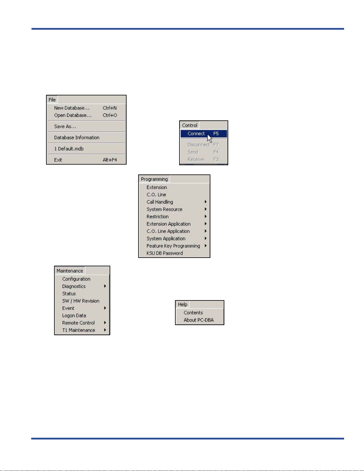
PC-DBA MAIN MENUS
Review the following menus to become more familiar with where the various options are for using, programming, and
maintaining PC-DBA.
The File menu provides you with all the
basic functions of handling the DB file.
The Control menu provides you with the
capability to connect PD-DBA to the switch
for sending a receiving information.
The Send and Receive options will not be
available until successful connection has
been made between the PC-DBA and the
switch.
The Programming menu provides you
with a variety of programming options for
customizing the DB/system to work
efficiently and cohesively in the current
environment.
The Maintenance menu monitor and test
several aspects of the operation and use of
the database and system usage.
The Help menu gives you access to the online
help system that contains detailed
programming information (much like this
document). There is also an option that allows
you to view specific information about the PCDBA software (e.g., version, etc.).
- 11 -
Page 20
PROGRAMMING VIA PC-DATABASE ADMINISTRATION (PC-DBA) DX-120 Programming Manual
Database Save and Restore
The working directory is the location allocated in the PC for all changes while the PC-DBA programming session is in
progress.
databases.
SAVING THE DATABASE
You may want to save the data in this directory for later retrieval since you may be working on many various
CAUTION!
Always perform a database SAVE prior to database RESTORE if you intend to
preserve the current contents of the working directory.
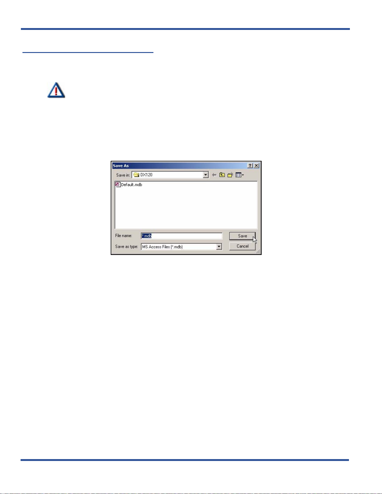
From the PC-DBA main screen:
1) Go to FileXSave As... to display the Save As dialog box.
• This dialog box allows you to enter a name for the database.
2) Enter the desired database name.
• You can also change the directory if necessary.
3) Click Save to store the database with that name.
• This dialog box allows you to select the desired database file.
4) Select (or enter the name of) the database you wish to restore.
5) Click Open to open the specified database.
• The system will use this database file until you specify a different name or close the application.
Database Save and Restore (continued on next page)
- 12 -
Page 21
DX-120 Programming Manual PROGRAMMING VIA PC-DATABASE ADMINISTRATION (PC-DBA)
Database Save and Restore (continued)
RESTORING (OPENING) A STORED DATABASE
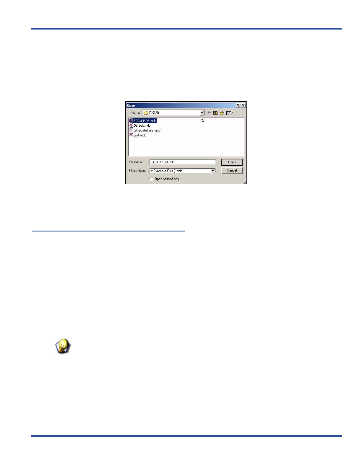
From the PC-DBA main screen:
1) Go to FileXOpen Database... to display the Open dialog box.
• This dialog box allows you to select the desired database file.
2) Select (or enter the name of) the database you wish to restore.
3) Click Open to open the specified database.
• The system will use this database file until you specify a different name or close the application.
Connecting PC-DBA to the Switch
When using the programming options of PC-DBA, the r e ar e tim es wh en you nee d to send an d re ce ive infor m at ion
between PC-DBA and the switch. However, before data can be exchanged between the PC and the DX-120 system,
you must make a connection between the two devices.
link.
There are specific tasks that can only be performed af ter a successful conne ction between PC-DBA and the switch has
been made:
• Receiving (data from the switch) - see page18
• Sending (data to the switch) - see page19
• Initializing the System (cold and warm starts) - see page21
• Diagnostics and T1 Maintenance - see page480
•
HINT
Also see...For specific information about making a physical connection between
PC-DBA and the switch, be sure to review the Vertical DX-120 Installation and
Maintenance Manual available on the Vertical CCC web site (www.vertical.com/ccc).
This connection is a serial (RS-232 – COM port or modem)
Connecting PC-DBA to the Switch (continued on next page)
- 13 -
Page 22

PROGRAMMING VIA PC-DATABASE ADMINISTRATION (PC-DBA) DX-120 Programming Manual
Connecting PC-DBA to the Switch (continued)
Once you make this connection, you can connect to the DX -120 system processor and download (receive) the DX-120
database memory to the PC-DBA laptop working directory.
A connection can be made either on-site or remotely:
ON-SITE (CABLE) CONNECTION
While on-site, you can connect the PC to the DX-120 via a standard RS-232C “straight-through” cable. You can
connect the DX-120 system on site via the PC serial port (COM port).
the PC serial port to the DX-120 CPM – PC-DBA port.
Use a straight-through 9-pin to 9-pin cable from
REMOTE (MODEM) CONNECTION
When you are accessing the system remotely you can make this connection via a modem.
1) Make the physical connection (cable or modem) between the PC and the DX-120 system.
From the PC-DBA main screen:
2) Go to ControlXConnect on the to display the password screen.
OR
Press F5 to display the password screen.
HINT
If the password screen does not appear, make sure that the physical connection is in
tact.
3) Enter the Database Administration password.
• At default, this password is eight spaces (i.e., press the space bar eig ht times).
• For information about changing the password, see “Changing Database Administrator Password” on
page 16.
- 14 -
Page 23

DX-120 Programming Manual PROGRAMMING VIA PC-DATABASE ADMINISTRATION (PC-DBA)
4) Click the OK button to display the next Connect screen that provides the curre n t (l oc al an d re m ote )
settings for the connections.
5) Make any necessary changes to the connection settings (as described on next page):
IMPORTANT!
• For local settings, make sure that you have the appropriate Baud rate and COM
Port settings.
• For remote settings, make sure you have all the necessary modem settings
entered (including the init string, modem name, baud rate, and phone number).
HINT
Refer to the following pages:
• Setting Up Optional Internal Modem - page 93
• Specifying PC-DBA Transmit Rate - page 95
• Selecting SMDR Transmit Rate - page 97
AND/OR
- 15 -
Remote (modem) Connection (continued on next page)
Page 24

PROGRAMMING VIA PC-DATABASE ADMINISTRATION (PC-DBA) DX-120 Programming Manual
Remote (modem) Connection (continued)
Click Connect to being the connection process.
• Several brief messages will be displayed to let you know what's happening during this process (e.g.,
sending the password, connection request, successful connection).
• Once connection is successfully established, a red dot will appear in the lower left corner of the
screen...
A red dot appears here when
there is an active connection
between the PC-DBA and the
switch.
6) You can now perform any of the tasks listed above (e.g, Receive, Send, Diagnostics, Initialize, T1
Maintenance).
Changing Database Administrator Password
The DX-120 system allows you to set up and maintain the system database using any DX-120 DET telephone, once
you have entered the database administrator password.
PC-DBA. It’s a good idea to change this password after the installation of the system.
Before changing the database administrator password, you must first connect to the DX-120 switch.
From the PC-DBA main screen:
1) Connect to PC-DBA to the switch (see 13).
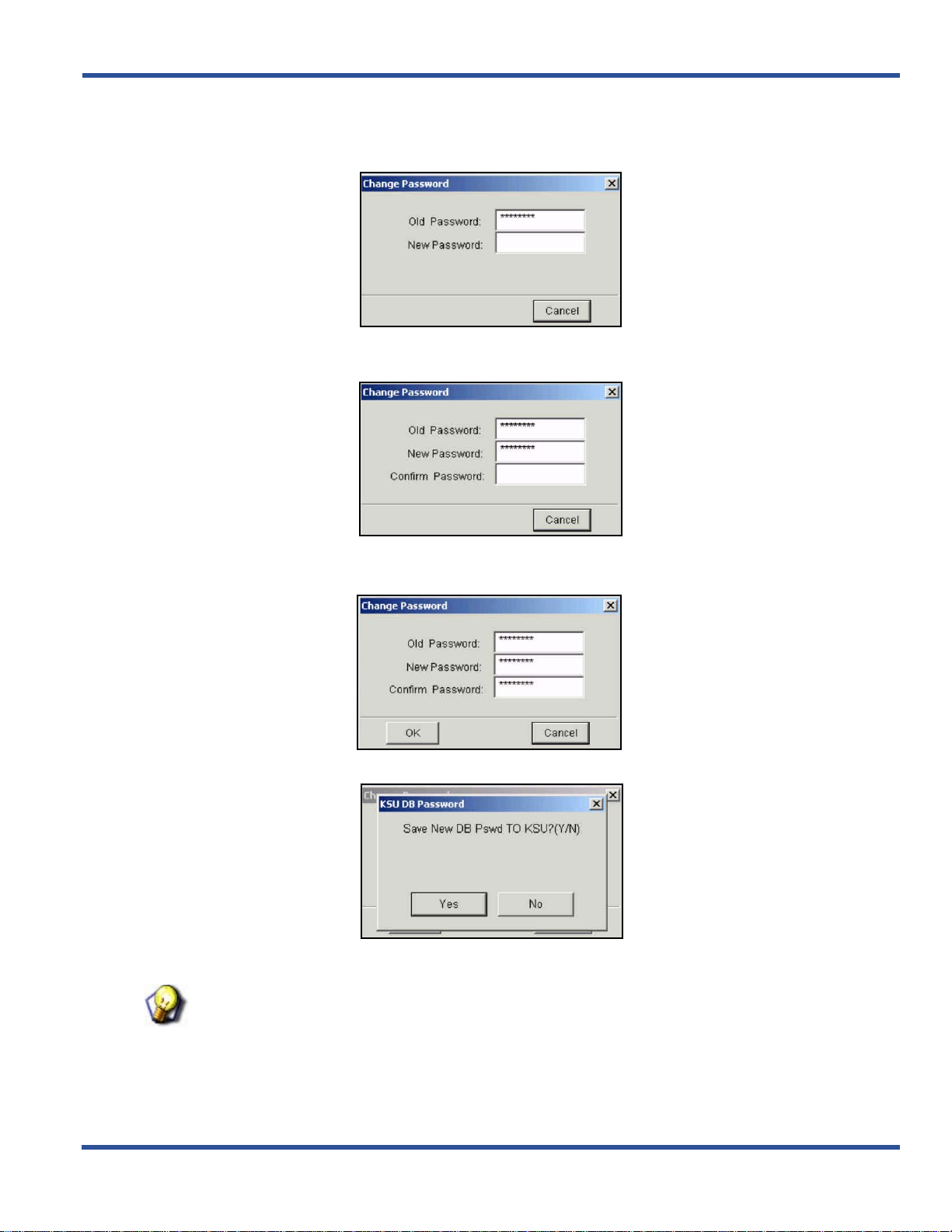
2) Go to ProgrammingXKSU DB Password to display the password change screen.
3) Enter the existing (old) password.
• When you enter text in this field, a new field will appear (i.e., New Password).
This password also allows you to program the system using
Changing Database Administrator Password (continued on next page)
- 16 -
Page 25
DX-120 Programming Manual PROGRAMMING VIA PC-DATABASE ADMINISTRATION (PC-DBA)
Changing Database Administrator Password (continued)
4) Enter the new password.
• When you enter text in this field, a new field will appear (i.e., Confirm Password).
5) Enter the new password again to confirm it.
• When you enter text in this field, an OK button will appear.
6) Click OK to change the password as designated in the previous steps.
• A message will appear to ask you to confirm that you want to make the change.
7) Click Yes to change the password and display a confirmation as the password is successfully change d.
HINT
Also see “Changing Database Administrator Password” on page 16.
- 17 -
Page 26
PROGRAMMING VIA PC-DATABASE ADMINISTRATION (PC-DBA) DX-120 Programming Manual
Receiving Data from the Switch
Before data can be exchanged between PC-DBA and the DX-120 system, you must Connect (F5) to the switch. After
you establish a successful connection between the DX-120 processor and the PC-DBA software, the system displays
the word Connect at the bottom of the screen, next to the time and date.
CAUTION!
• When you receive programming from the switch, the system overwrites the
corresponding programming on your PC with the settings from the switch.
Make sure you want to do this before proceeding.
• Always perform a Database Save (All) before a Database Receive (All)
operation if you want to preserve the current contents of the working
directory on the laptop.
• It is recommended that if you are making databa se chan ges to a syste m that
has been in operation for an extended period of time, that you perform a
Receive All operation prior to making any database changes on the laptop.
• Since some database fields (including Speed Dial and Service Mode) are
user adjustable, these fields will be overwritten if you perform a Send All
operation using an outdated PC-DBA laptop database.
From the PC-DBA main screen:
1) Connect PC-DBA to the switch.
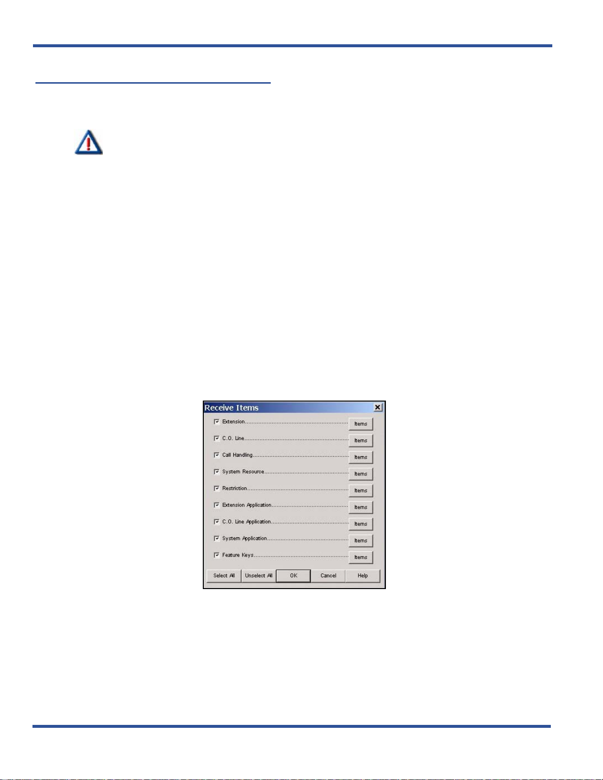
2) Go to ControlXReceive to display a list of categories that represent the information that can be received.
OR
Press F3 to display a list of categories that represent the information that can be received.
3) Locate the category that represents the information you want to receive.
4) Click the Items button to display the list of various options for that category.
Receiving Data from the Switch (continued on next page)
- 18 -
Page 27

DX-120 Programming Manual PROGRAMMING VIA PC-DATABASE ADMINISTRATION (PC-DBA)
Receiving Data from the Switch (continued)
5) Click on the specific items you want to receive to select them.
OR
Click Select All to select all the items on that screen.
• Use the Unselect All button to deselect all items on the page. You can then reselect any specific items
as needed.
6. Click OK when all your selections have been made to begin the receiving process and download the
data from the switch to your PC/laptop.
HINT
Refer to the following pages:
• Connecting PC-DBA and the Switch - page 13
• Sending Data to the Switch - page 19
• Disconnecting PC-DBA from the Switch - page 21
Sending Data to the Switch
Before data can be exchanged between PC-DBA and the DX-120 system, you must Connect (F5) to the switch. After
you establish a successful connection between the DX-120 processor and the PC-DBA software, the system displays
the word Connect at the bottom of the screen, next to the time and date.
CAUTION!
• When you receive programming from the switch, the system overwrites the
corresponding programming on your PC with the settings from the switch.
Make sure this is what you want to do before proceeding.
• Always perform a Database Save (All) before a Database Receive (All)
operation if you want to preserve the current contents of the working
directory on the laptop.
• It is recommended that if you are making dat abase chan ges to a sy stem tha t
has been in operation for an extended period of time, that you perform a
Receive All operation prior to making any database changes on the laptop.
• Since some database fields (including Speed Dial and Service Mode) are
user adjustable, these fields will be overwritten if you perform a Send All
operation using an outdated PC-DBA laptop database.
From the PC-DBA main screen:
1) Connect PC-DBA to the switch.
2) Go to ControlXSend to display a list of categories that represent the information that can be sent.
OR
- 19 -
Sending Data to the Switch (continued on next page)
Page 28

PROGRAMMING VIA PC-DATABASE ADMINISTRATION (PC-DBA) DX-120 Programming Manual
Sending Data to the Switch (continued)
3) Press F4 to display a list of categories that represent the information that can be sent.
Click on these buttons to
display the list of options for
the corresponding category.
4) Locate the category that represents the information you want to receive.
5) Click the Items button to display the list of various options for that category.
6) Click on the specific items you want to receive to select them.
OR
7) Click Select All to select all the items on that screen.
• Use the Unselect All button to deselect all items on the page. You can then reselect any specific items
as needed.
8) Click OK when all your selections have been made to begin the receiving p rocess and downloa d the dat a
from the switch to your PC/laptop.
HINT
Refer to the following pages:
• Connecting PC-DBA and the Switch - page 13
• Receiving Data from the Switch - page 18
• Disconnecting PC-DBA from the Switch - page 21
- 20 -
Page 29

DX-120 Programming Manual PROGRAMMING VIA PC-DATABASE ADMINISTRATION (PC-DBA)
Disconnecting PC-DBA from the Switch
After you have finished using the link between the DX-120 and PC-DBA, you should disconnect this link. The system
can be disconnected either automatically or manually:
AUTOMATIC DISCONNECTION
The system disconnects automatically if:
• the physical connection path (cable or modem connection) is interrupted (not recommended)
• you exit PC-DBA while the link is active (not recommended)
• after several minutes it senses that someon e has not been using the associated tools that require co nnection (i.e.,
it automatically times itself out).
MANUAL DISCONNECTION
From the PC-DBA main screen:
1) Go to ControlX Disconnect to disconnect the system from the switch.
OR
2) Press F7 to disconnect the system from the switch.
Once this disconnection is complete:
3) Disconnect any physical connection (cable or modem) between the PC and the switch system as
appropriate.
Initializing (F8) The System
In the programming process it is often desirable to revert to factory defaults (cold start). The Initialize function allows
you to revert the database settings to the factor y default s.
can click the Initialize button or press F8 to initialize the current category.
Keep in mind that when you use Initialize, the system saves the restored data only when you exit the screen you are
on.
The system then only sends it to the DX-120 switch database when you perform the F4-Send operatio n.
You can also initialize (i.e., reset) the system without reverting back to factory defaults and reloading the database
(warm start).
NOTE
You can initialize all of the PC-DBA parameters when you install a new system. After
you perform a cold start, connect to the DX-12 0 processor by clicking Connect or
pressing F5. Then click Receive or press F3 to perform a Receive All and download
all factory settings to a new database file on the PC.
HINT
Also refer to the Vertical DX-120 Installation and Main tenance Manual which can be
found on the Vertical CCC website (
While using the various database progr amming menus, you
www.vertical.com/service-login.html).
- 21 -
Initializing the System (continued on next page)
Page 30
PROGRAMMING VIA PC-DATABASE ADMINISTRATION (PC-DBA) DX-120 Programming Manual
Initializing the System (continued)
PERFORMING A COLD START
Use Software COLD Start to cause the system to restart operations and reload default customer database data.
CAUTION
USE THIS FEATURE WITH CARE!
This operation requires confirmation since all calls in progress will be
disconnected and the current database will be erased!
NOTE
Once you run this operation, connection between the switch and PC-DBA will be lost.
Therefore, you will have to re-connect to the switch.
After you connect the PC-DBA to the switch:
From the main PC-DBA Screen:
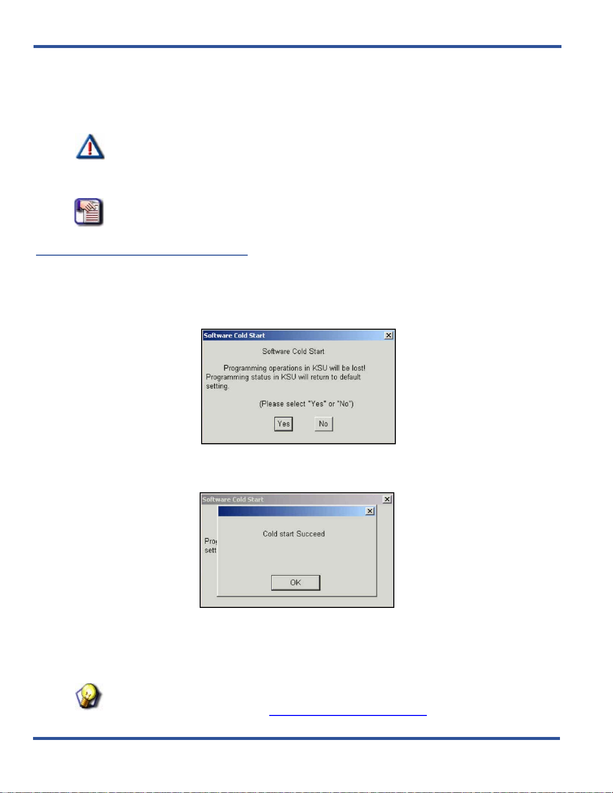
1) Go to MaintenanceXRemote ControlXSoftware Cold Start to display a prompt warning you about what
will happen if you continue with this process (i.e. programming operations will be lost, then returned to
default settings).
2) Click Yes to execute the Cold Start.
• A message will appear to confirm that a cold start was successfully completed.
OR
Click No to cancel the Cold Start and close the warning prompt.
3) Click OK to close the window.
HINT
Also refer to the Vertical DX-120 Installa tion and Maintenance Manual which can be
found on the Vertical CCC website (www.vertical.com/service-login.html).
- 22 -
Page 31

DX-120 Programming Manual PROGRAMMING VIA PC-DATABASE ADMINISTRATION (PC-DBA)
PERFORMING A WARM START
Use the Warm Start process to cause the system to restart its operations without reloading or affecting the stored
database (e.g., if some how one or more ports lock up, etc.).
CAUTION
USE THIS FEATURE WITH CARE!
This operation requires confirmation since all calls in progress will be
disconnected.
NOTE
Once you run this operation, connection between the switch and PC-DBA will be lost.
Therefore, you will have to re-connect to the switch.
After you connect the PC-DBA to the switch:
From the main PC-DBA Screen:
1) Go to MaintenanceXRemote ControlXSoftware Warm Start to display a prompt warning you about what
will happen if you continue with this process. (i.e., all system process will be discontinued and any calls in
progress will be disconnected).
2) Click Yes to execute the Warm Start.
• At the end of the process a message will appear to confirm that a warm start was successfully
completed.
OR
Click No to cancel the Warm Start and close the warning prompt.
3) Click OK to close the window.
HINT
Also refer to the Vertical DX-120 Installation and Main tenance Manual which can be
found on the Vertical CCC website (www.vertical.com/service-login.html).
- 23 -
Page 32
PROGRAMMING VIA PC-DATABASE ADMINISTRATION (PC-DBA) DX-120 Programming Manual
Getting Help (F1)
You can access Help via the main menu bar or from any scr ee n withi n th e pr og ra m .
From the PC-DBA main screen:
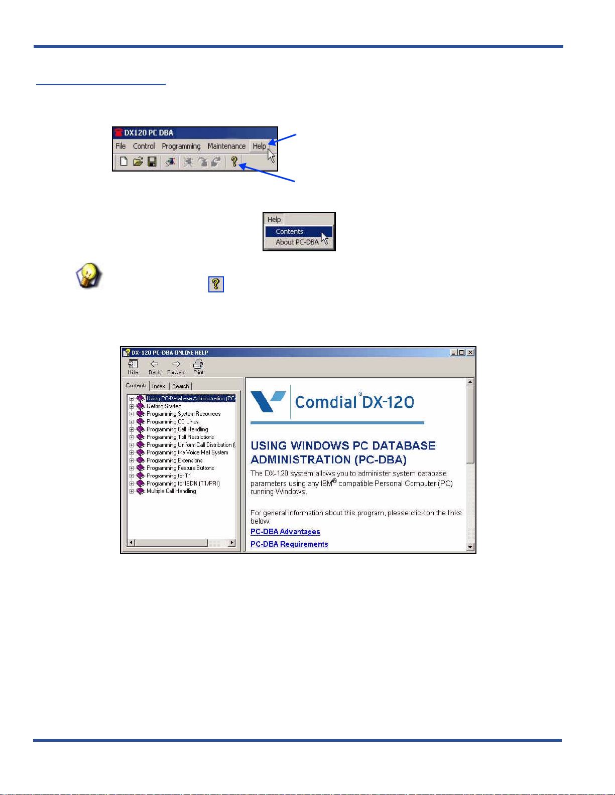
Click here to display a list of options.
OR
Click here to display the first page of the online help.
1) Click on the Help option on the main menu bar.
HINT
You can also click on to display the first page of the online help (then, skip to step 3).
2) Selecting Contents to display the main Help screen.
• If you select About PC-DBA you will get information about the version of PC-DBA currently running on
your system.
3) Use the tabs (Contents, Search, Index) to find a specific topic for which you need help.
OR
Getting Help (continued on next page)
- 24 -
Page 33

DX-120 Programming Manual PROGRAMMING VIA PC-DATABASE ADMINISTRATION (PC-DBA)
Getting Help (continued)
From a specific screen within the program:
1) Press F1 for any individual screen within the progr am to display the corresponding page from Help for that
screen.
OR
2) Click on any individual screen within the program to display Help for that screen.
EXAMPLE
1
Click on the Help button
from any screen...
2
...to display the corresponding page in online help.
HINT
If you are unable to find the information yo u nee d in the Help system, cont act Vertical
Technical Support for assistance.
- 25 -
Page 34

USING ANY DIGITAL EXTENSION TELEPHONE (DET) DX-120 Programming Manual
USING ANY DIGITAL EXTENSION TELEPHONE (DET)
The DX-120 system allows you to program system database parameters using any DX-120 DET. It is possible to
program the DX-120 system while the telephone is in use; however, certain button operations are used during
programming and cannot be used for telephone call processing. Therefore, Vertical suggest s not using these fe atures
simultaneously unless you have been directed to do so by the servicing technician.
The Database Administration password is set by default to ######## (eight #s). You can use any combinatio n of
alphanumeric characters using the conventions of extension/CO line name.
Entering the Database Administration Mode
1) Press Feature, then # * to enter Database Administration.
• The system then prompts for the system Database Administration password.
• The default set at the factory is ########.
2) Enter the password and press show (show is an LCD interactive button).
• After you have correctly entered the password, the system gives you acces s to Database
Administration.
• You can also chan ge the passwo rd at any time - see “Changing Da tabase Ad ministration Password” on
page 27.
LCD Interactive Buttons
The LCD interactive buttons are essential to completing database programming tasks. These buttons take on many
functions while in the database administration mode. LCD interactive buttons include the following.
• next —moves the cursor to the next item or parameter
• back—moves the cursor back one item or parameter
• show—shows the contents of the current item or parameter
• chg—changes the contents of the current item or parameter
• bksp—when you are entering data, backspaces over what you entered so you can correct it
• save—saves entered data
- 26 -
Page 35

DX-120 Programming Manual USING ANY DIGITAL EXTENSION TELEPHONE (DET)
Database Item Select Screen
After you enter the correct password and press show, the system opens DX-80 Database Administration an d displays
the Database Item Select screen. This screen allows you to skip to the necessary database item for immediate
programming of that item. The coding instructions you enter for each database item correspond to the following list:
To Program Enter
EXTENSION 01-
CO LINE 02-
CALL HANDLING 03-
SYSTEM RESOURCE 04-
RESTRICTION 05-
EXTENSION APPLICATION 06-
CO LINE APPLICATION 07-
SYSTEM APPLICA TION 08-
EXAMPLE
To skip to the extension application section of database administration, enter 06 at
the DB Item Select screen and press save. If you want instead to go to system
resources, enter 04 at the DB Item Select screen and press save.
Exiting Database Administration
To exit the Database Administration when you are finished program ming or need to perform another t ask (e.g., make a
phone call):
Press the SPK button twice.
OR
Lift and replace the handset in the hook-switch cradle.
Changing Database Administration Password
1) Press Feature, then # * to enter Database Administration.
• The system then prompts for the system Database Administration password.
• The default set at the factory is ########.
2) Press show to display the DB Item Select screen.
3) Enter 04-01.
4) Press save to display to the System Resources – DB PSWD screen with the current password.
5) Press chg to change the password.
6) Enter a new eight-character, alphanumeric password.
IMPORTANT!
Press # after entering each character that makes up the password.
7) Press save.
8) Exit the programming mode.
- 27 -
Page 36

THIS PAGE INTENTIONALLY LEFT BLANK
Page 37

DX-120 Programming Manual
SECTION 3 - GETTING STARTED
OVERVIEW
Before beginning to program a new system, it is important that you determine what configuration will best meet your
customer’s needs.
The DX-120 Numbering Plan contains all of the configuration defaults provided with the system. If you need settings
other than those provided, you will need to customize the Numbering Plan. Since you will be programming aspects
that can be affected by the Numbering Plan, it is best to customize the plan before programming the remainder of the
system. For details on modifying the default Numbering Plan see
SHORTCUTS THAT HELP YOU WORK FASTER
Vertical also provide s you with some tools you can use to reduce your programming time. These tools include:
• a series of worksheets for you to plan your system structure, and to record the programming for future re ference if
necessary. These worksheets are provided in
• using one of four standard database programming templates provided with the DX-120 product CD. You can
choose the template that most closely matches your new customer’s site needs, and then add whatever custom
changes you need to make. This approach saves you the time of programming the entire system from scratch.
• copying a baseline CO line or extension’s setups to several other CO line or extensions, thereby eliminating the
need to program them individually.
• using the directory number/feature number lookup when you need to know a specific directory number or feature
code you need to enter at the DET speakerphone, and
• resetting an extension to its default settings during troubleshooting and fault isolation procedures.
• In addition, button label templates for customizing individual DET button definitions are provided in Appendix B,
Button Labeling.
Appendix A, Worksheets.
“Customizing the Numbering Plan” on page 103.
Using a Database Programming Template
Six programming templates have been provided that you may use as a shortcut when setting up your customer’s
database; one template with no voice mail and five templates with voice mail options.
• You can copy the template that is closest to your cu stomer’s requirements, and then customize it further if
necessary to further meet their needs.
• These six database templates are provided on the DX-120 pro duct CD.
• While you are not allowed to modify the templates on the CD, you can download them to your laptop and then
customize them further as needed.
CAUTION
• These templates are provided to reduce your programming time when
setting up a new system. You can use them for existing sys tems, but you will
lose whatever custom settings are currently in place on that system.
• Be aware of this when downloading a template from PC-DBA to an existing
system with a lot of customized features, as you will have to reprogram
those features.
HINT
For further details on using the database templates, refer to the Read Me file on the
DX-120 product CD.
- 29 -
Page 38

SHORTCUTS THAT HELP YOU WORK FASTER DX-120 Programming Manual
Copying Baseline CO Line Setups
This is a programming aid feature. Once you have programmed one CO line for the baseline configuration settings,
you can copy those setting to other CO lines using this utility. Copying these setups requires two separate procedures
whether you program via PC-DBA or by DET:
You must:
A) Program the CO Line Setup to be copied
B) Copy the programmed CO Line Setup - Setups can be copied one line at a time or several lines at a time
COPYING BASELINE CO LINE SETUPS VIA PC-DBA
PROGRAM THE CO LINE SETUP TO BE COPIED
See “Section 5 - Programming C.O. Lines” for additional information about programming C.O. lines
COPY THE PROGRAMMED CO LINE SETUP
From the PC-DBA main screen:
1) Go to ProgrammingXSystem ApplicationXConfiguration Copy to display the Configuration Copy screen.
Copy the line(s) as needed:
Copy CO Lines One at a Time
2) Locate the Individual area under CO Line Copy.
3) Select the CO line directory number you want to use as a baseline from the dropdown list in the Source
DIR No. field.
• Valid directory number s are 800 through 839.
• There is no default.
4) Select the CO line directory number into which you wa nt to copy the baseline’ s progra mming (800-839 ) in
the Destination DIR No. field.
5) Click Copy to make the specified copy.
• Enter any other CO line numbers as needed using the steps above.
• If needed, you can enter another source CO line directory number to copy from, and continue the
process for other CO lines.
Now... continue on to step 6 on the following page.
OR
Copy the Programmed CO Line Setup via PC-DBA (continued on next page)
- 30 -
Page 39

DX-120 Programming Manual SHORTCUTS THAT HELP YOU WORK FASTER
Copy the Programmed CO Line Setup via PC-DBA (continued)
Copy a CO Line Setup to All the Lines in a Line Group
2) Locate the Group area under CO Line Copy.
3) Select the CO line directory number you want to use as a baseline from the dropdown list in the Source
DIR No. field.
• Valid directory numbers are 800 through 839.
• There is no default.
4) Select the CO group number into which you want to copy the baseline’s programmin g (9 and 740 throu gh
746) in the CO Group field.
5) Click Copy to make the specified copy.
• Enter any other CO group numbers as needed using the steps above.
Now... continue on to step 6 below.
When all copies have been made:
6) Click the Update button to enter and save your settings into the database on your local disk.
7) Click the Close button to exit the current screen and return to the PC-DBA main screen.
Once all database changes have been completed:
8) Perform a SEND to copy the database changes to the DX-120 switch system memory.
COPYING BASELINE CO LINE SETUPS VIA THE DET
PROGRAM THE CO LINE SETUP TO BE COPIED
See “Section 5 - Programming C.O. Lines” for additional information about programming C.O. lines
COPY THE PROGRAMMED CO LINE SETUP
NOTE
• chg, bksp, save, one, always, del, and ack are interactive LCD button operations.
Use the three buttons below the LCD display to activate the associated operation.
• You can press Hold at any time to return to the previous level or press the volume
buttons to return to the main DB selection screen.
1) Enter Database Administration (see page 26) using the feature code Feature # * to display a prompt for
the password.
2) Enter the DB Admin password.
Copy the Programmed CO Line Setup via the DET (continued on next page)
- 31 -
Page 40

SHORTCUTS THAT HELP YOU WORK FASTER DX-120 Programming Manual
Copy the Programmed CO Line Setup via the DET (continued)
Copy CO Lines One at a Time
3) Enter 08-11-01.
4) Press save to display the Individual CO Line Copy screen.
5) Press show to display the prompt: “COPY FROM”.
6) Enter the CO line directory number you want to use as a baseline.
7) Press save to display the prompt “COPY TO”.
8) Enter the CO line directory number you want to copy the baseline’s programming into (800-839).
9) Press save to store the copy and again display the prompt “COPY TO”.
• Continue entering CO line directory numbers CO lines to which you want to copy the baseline setups.
• Press save each time you enter a directory number.
10) Press the Hold button to return to the previous menu level.
OR
Press the Volume button (up or down) to return to the DB Item Selection screen.
OR
Exit programming (see “Exiting Database Administration” on page 27).
Copy a CO Line Setup to All the Lines in a Line Group
3) Enter 08-11-02.
4) Press save to displays the Group CO Line Copy screen.
5) Press show to display the prompt: “COPY FROM”.
6) Enter the CO line directory number you want to use as a baseline.
7) Press save to display the prompts “COPY TO”.
8) Enter the CO line group directory number into which you want to copy the baseline’s programming (9,
740-746).
9) Press save to store the setups to all of the CO lines that are part of that CO line group.
• The system prompts “COPY TO” again so that you can save the setup s to another line group if desir ed.
• Continue entering CO line group directory numbers where you want to save the baseline setup.
• Press save each time you enter a CO line group directory number.
10) Press the Hold button to return to the previous menu level.
OR
Press the Volume button (up or down) to return to the DB Item Selection screen.
OR
Exit programming (see “Exiting Database Administration” on page 27).
- 32 -
Copy the Baseline Setups (continued on next page)
Page 41

DX-120 Programming Manual SHORTCUTS THAT HELP YOU WORK FASTER
Copy Baseline Setups (continued)
COPYING BASELINE EXTENSION SETUPS
You can use this database feature to quickly copy the various programming and settings for one extension to other
extensions. Copying these setups requires two separate procedures whether you program via PC-DBA or by DET:
You must:
A) Program the Baseline Extension Setup to be copied
B) Copy the programmed Baseline Extension Setup - Setups can be copied one line at a time or several lines at a
time
COPYING BASELINE EXTENSION SETUPS VIA PC-DBA
PROGRAM THE BASELINE EXTENSION SETUP TO BE COPIED
See page “Section 10 - Programming Extensions” on page 385 for information about programming baseline
extensions.
NOTE
When using group copy, all extensions you want to receive th e progr amming must be
programmed for the same pickup group.
From the PC-DBA main screen:
1) Go to ProgrammingXSystem ApplicationXConfiguration Copy to display the Configuration Copy screen.
Copy the line(s) as needed.
Copy Individual Extension Settings
2) Locate the Individual area under Extension Copy.
3) Select the extension directory number you want to use as a baseline from the dropdo wn list in the Ext DIR
No. field.
• You can enter any valid extension number in the system.
• There is no default.
4) Select the extension directory number (from the Ext DIR No. field to the right of the arrow) into which you
want to copy the baseline’s programming (i.e., any valid exte n sio n) .
5) Click on Copy to copy the specified settings.
• Enter any other extension numbers as needed using the steps above.
• If needed, you can enter another source extension number to copy from, and continue the process for
other extensions.
Now... continue on to step 6 on the next page.
OR
Copy the Programmed CO Line Setup via PC-DBA (continued on next page)
- 33 -
Page 42

SHORTCUTS THAT HELP YOU WORK FASTER DX-120 Programming Manual
Copy the Programmed CO Line Setup via PC-DBA (continued)
Copy All Lines in a Pickup Group
2) Locate the Group area under Extension Copy.
3) Select the extension number you want to use as a baseline from the dropdown list in the Ext DIR No. field.
• You can enter any valid extension number in the system.
• There is no default.
4) Select the pickup group number (from the Pickup Group field) into which you want to copy the baseline
programming (i.e., any valid pickup directory number).
5) Click on Copy to make the specified copy.
• Enter any other pickup group numbers as needed using the steps above.
• If needed, you can enter another source extension directory number to copy from, and continue the
process for other pickup groups.
Now... continue on to step 6 on the next page.
When all extensions or pickup group settings are copied:
6) Click the Update button to enter your settings into the database on your local disk.
7) Click the Close button to exit the current screen and return to the PC-DBA main screen.
When you have finished all programming changes:
8) Perform a SEND to copy the database changes to the DX-120 switch system memory.
COPYING BASELINE EXTENSION SETUPS VIA THE DET
PROGRAM THE CO LINE SETUP TO BE COPIED
“Section 5 - Programming C.O. Lines” for detailed information about programming C.O. lines
COPY THE PROGRAMMED CO LINE SETUP
NOTE
• chg, bksp, save, one, always, del, and ack are interactive LCD button operations.
Use the three buttons below the LCD display to activate the associated operation.
• You can press Hold at any time to return to the previous level or press the volume
buttons to return to the main DB selection screen.
1) Enter Database Administration (see page 26) using the feature code Feature # * to display a prompt for
the password.
2) Enter the DB Admin password.
Copy the Programmed Baseline Extension Setups via the DET (continued on next page)
- 34 -
Page 43

DX-120 Programming Manual SHORTCUTS THAT HELP YOU WORK FASTER
Copy the Programmed Baseline Extension Setups via the DET (continued)
Copy Individual Extension Settings
3) Enter 08-12-01.
4) Press save to display the “INDIVIDUAL COPY” programming screen.
5) Press show to display the prompt: “COPY FROM”.
6) Enter the extension directory number you want to use as a baseline.
7) Press save to display the prompt: “COPY TO”.
8) Enter the extension number into which you want to copy the baseline setups into.
9) Press save to store the copy and again display the prompt “COPY TO”.
• Use the steps above to copy other extensions as needed.
• Press save each time you copy an extension.
10) Press the Hold button to return to the previous menu level.
OR
Press the Volume button (up or down) to return to the DB Item Selection screen.
OR
Exit programming (see “Exiting Database Administration” on page 27).
Copy All Lines in a Pickup Group
1) Enter 08-12-02.
2) Press save to display the “GROUP COPY” programming screen.
3) Press show to display the prompt: “COPY FROM”.
4) Enter the extension directory number you want to use as a baseline.
5) Press save to display the prompt: “COPY TO”.
6) Enter the pickup group number into which you want to copy the base lin e set ups into.
7) Press save to copy the programming of the baseline extension into all the extensions in the specified
pickup group and again display the prompt: “COPY TO”.
• Use the steps above to copy programming to other pickup groups.
8) Press the Hold button to return to the previous menu level.
OR
Press the Volume button (up or down) to return to the DB Item Selection screen.
OR
Exit programming (see “Exiting Database Administration” on page 27).
- 35 -
Page 44

SHORTCUTS THAT HELP YOU WORK FASTER DX-120 Programming Manual
Feature / Directory Number Lookup
The DX-120 system has many features and codes, and at times it may be difficult to remember the code for the
necessary feature. The DX-120 has a built-in feature code directory to allow you to look up the codes from a DET
phone.
While the telephone is idle (no call activity):
1) Press Feature # 5 to display the following screen:
2) Use the corresponding method shown below and on the following pages to find the needed number or
code.
When you want to exit Feature/Directory Number Lookup:
3) Go off-hook, then on-hook (or press the ON/OFF button twice) to exit.
FIND A SYSTEM DIRECTORY NUMBER
1) Press dir to display the first screen of directory number listings (see 471 for a listing of the default
directory numbers).
2) Press next (and/or back) to move through the list until you see the item you want to select.
AND/OR
Press Hold to go back to a previous screen level.
When you find the item you want to use:
3) Press the button that corresponds to the item you want to display the appropriate number for tha t item .
EXAMPLE
To show the directory number assigned to CO line groups, press the button that
corresponds to co gp.
4) Make a note of that number for future reference.
FIND A FEATURE ACCESS CODE
1) Press ftr to display the available features listed alphabetically and abbrev iated (see 472 for a listing of the
default feature access codes).
2) Press next (and/or back) to move through the list until you see the feature you want to select.
AND/OR
Press Hold to go back to a previous screen level.
Once you find the code you want:
3) Make a note of the code for future reference.
Feature / Directory Number Lookup (continued on next page)
- 36 -
Page 45

DX-120 Programming Manual SHORTCUTS THAT HELP YOU WORK FASTER
Feature / Directory Number Lookup (continued)
FIND A SUFFIX CODE
1) Press suffix to display a list of digits dialed after system resource directory numbers displays (see page
474 for a listing of the default suffix codes).
2) Press next (and/or back) to move through the list until you see the suffix you want to select.
AND/OR
Press Hold to go back to a previous screen level.
When you find the number you want to use:
3) Press the button that corresponds to the suffix you want to select.
Resetting an Extension to the Default Set
When extension users have invoked several features on their extensions, it may be necessary to clear all settings and
return the telephone set to the factory condition. The Default Set code is used to perform this operation.
The following extension parameters are reset to the value shown:
• LNR = empty
• SNR = No Saved Number
• Memo = No Saved Number
• Telephone Lock = No
• Auto Hold = No
• Page Receive = Yes
• Busy Ring = Yes
• Hotline to = NULL (none)
To return an extension’s settings to the default settings:.
1) Press Feature 6 9 to display the prompt:
2) Press go to load the default set into the phone.
• You will hear the confirmation tone when the operation is complete.
- 37 -
Page 46

THIS PAGE INTENTIONALLY LEFT BLANK
Page 47

DX-120 Programming Manual
SECTION 4 - PROGRAMMING SYSTEM RESOURCES
OVERVIEW
The system features allow you to control system administration and to assign system resources. The DX-120 provides
programmable features that allow you to establish these various settings.
BASIC SYSTEM PROGRAMMING TASKS
CAUTION
Database changes reside only on your computer. When you have finished making all
changes to the database, perform a SEND operation to download the new database to
the DX-120 switch.
• Assign the attendant extension for each tenant group - see page 40
• Assign the system reminder for each tenant group - see page 45
• Set up the system time, date, and hour mode - see page 49
• Set up the ring scheme - see page 55
• Name each CO line - see page 58
• Set up the pre-programmed incoming and outbound messages - see page 60
• Program speed dial numbers - see page 64
• Set Caller ID in the CID Names and Assignments table - see page 72
• Establish the music source for the each tenant group - see page 83
• Assign the external pager a tenant group - see page 77
• Establish Loud Bell Setting - see page 80
• Assign the DSS port owner - see page 89
• Set up the optional internal modem - see page 93
• Select the PC-DBA transmit rate - see page 95
• Select the SMDR transmit rate - see page 97
• Set up/modify the numbering plan you want to use - see page 103
• Set the daylight savings time feature - see page 287
• Set the user passwords and names for extensions - see page 387
• Specify the letter type - see 476
- 39 -
Page 48

BASIC SYSTEM PROGRAMMING TASKS DX-120 Programming Manual
Assigning Attendants
You assign a primary attendant to each of the DX-120 system’s three tenant groups. The standard Digital
Speakerphone serves as the attendant telephone.
system functions like line recall, forced incoming ICM call forward, and manual evening or alternate service mode
operation.
attendant extension has an internal call queue that allows multiple intercom calls to be directed to the attendant at the
same time.
You can designate an alternate attendant position in each tenant group for common sharing of incoming CO line calls
or load sharing during peak traffic periods.
• The attendant’s extension has (with a password) control of:
• Y ou can connect the attendant e xtension to any system st ation port, and yo u can assign it an y intercom extension
• The following conditions apply to the attendan t ext en sio n:
The attendant receives all intercom calls directed to the attendant directory number (“0” at default). The
- System Service Mode (day/evening/alternate/time)
- Time of Day Settings
- System Speed Dial Number Programming
- Recording of the Optional Auto Attendant Greetings
number in your numbering plan (see
- Any extension in the tenant group can dial 0 to reach the attendant extension.
- The system routes all unanswered transferred calls and all calls from any extension that invokes forced
intercom call forward to the attendant exte nsio n . When multiple internal calls are waiting in queue for the
attendant extension, the display indicates on the second line the number of calls waiting in the queue.
“Customizing the Numbering Plan” on page 103).
When assigned as attendant, this extension supports general
- The extension password for the attendant extension is required for entry into attendant administration, caller
ID table and ring mode. The default extension password is 9999.
- Only the designated attendant extension can manually change the system ring mode or the extension room
status (hotel mode).
Attendant Extension (continued on next page)
- 40 -
Page 49

DX-120 Programming Manual BASIC SYSTEM PROGRAMMING TASKS
Attendant Extension (continued)
• Features settings that can affect the attendant extension include the following.
- Do Not Disturb (i.e., forced DND)
- Hotel Mode
- Room Status (F7#)
- Attendant Administration (F#0)
- Service Mode Change
- Auto Attendant Message Record/Review
- Temporary Service Mode
- System Speed Dial
- Call Forward Auxiliary Lamp
- Extension User Password (F97)
- Caller ID Table (review) (F6#)
- Ring Mode (F63)
• Once you have programmed the attendant extension (see page 40), program the user password for that
extension.
ASSIGNING ATTENDANTS VIA PC-DBA
From the PC-DBA main screen:
Assigning Attendants via PC-DBA (continued on next page)
- 41 -
Page 50

BASIC SYSTEM PROGRAMMING TASKS DX-120 Programming Manual
Assigning Attendants via PC-DBA (continued)
1) Go to ProgrammingXSystem ResourceXAttendant to display the Attendant screen.
• This screen has two parts: a table at the top that summarizes the current settings, and some entry
fields at the bottom that are used to change the information in the table.
2) Click on the line that corresponds to the tenant group you want to program
• "1" is highlighted initially.
IMPORTANT!
If you are not using a tenant group, leave the Attendant and Alternate fields blank.
3)Click the down arrow to the right of the Attendant field.
4) Scroll to the extension/directory number you want to use for the primary attendant
5) Click on that extension.
• Valid numbers are any extension within the tenant group you have not already assigned as an alternate
attendant.
• The default is 101.
6) Click in the middle of the screen to move the number you have selected into the table.
• Your selections are now entered for the tenant group you selected in Step 2.
Assigning Attendants via PC-DBA (continued on next page)
- 42 -
Page 51

DX-120 Programming Manual BASIC SYSTEM PROGRAMMING TASKS
Assigning Attendants via PC-DBA (continued)
Assign the Alternate Attendant Extension
If you do not wish to assign an alternate attendant extension, leave the field blank and skip to step 8.
7) Click the down arrow next to the Alternate field to display the list of available extensions.
• Follow steps 4 through 6 as shown above to set the Alternate Attendant extension.
• Follow steps 2 through 6 to assign primary and alternate attendant extension numbers to other tenant
groups
When you have completed all entries:
8) Click the Update button to enter and save your settings into the database on your local disk.
9) Click the Close button to exit the current screen and return to the PC-DBA main screen.
Once all database changes have been completed:
10) Perform a SEND to copy your new database to the DX-120 switch system memory.
- 43 -
Attendant Extension (continued on next page)
Page 52

BASIC SYSTEM PROGRAMMING TASKS DX-120 Programming Manual
Attendant Extension (continued)
ASSIGNING ATTENDANTS VIA THE DET
NOTE
• chg, bksp, save, one, always, del, and ack are interactive LCD button operations.
Use the three buttons below the LCD display to activate the associated operation.
• You can press Hold at any time to return to the previous level or press the volume
buttons to return to the main DB selection screen.
1) Enter Database Administration (see page 26) using the feature code Feature # * to display a prompt for
the password.
2) Enter the DB Admin password.
3) Press show to display the DB Item Select screen displays.
Program the attendant extension
4) Enter 04-02-x-01, where x is the tenant group number., then press save.
5) T o ch ange the designated a ttendant extension press chg. Enter the extension number you want to a ssign
as the attendant extension.
NOTE
You can only assign valid extension directory numbers as tenant group attendants.
You cannot use extensions that are programmed as attendants for other tenant
groups or as alternate attendants.
6) Press save.
Program the alternate attendant extension
7) Return to the Database Item Select screen by pressing the Volume button (up or down).
8) Enter 04-02-x-06, where x is the tenant group number.
9) Press save to save the setting.
To change the designated attendant extension
10) Press chg (change) to display the extension number prompt.
1 1 ) Enter the extension number you want to assign as the alternate attendant extension.
NOTE
You can only assign valid extension directory numbers as tenant group attendants.
You cannot use extensions that are programmed as attendants for other tenant
groups or as alternate attendants.
12) Press save to save the setting.
13) Program the user passwords (see “Assigning a User Password, Password Length, and/or Name to
Extensions” on page 387) for each attendant extension and alternate attend an t ex ten s io n you ha ve
programmed.
- 44 -
Page 53

DX-120 Programming Manual BASIC SYSTEM PROGRAMMING TASKS
Assigning System Reminders
You can set the DX-120 system to alert all phones at predetermined intervals during the day; you can choose up to
eight reminders.
The system uses the music source connected to the MC1 connector for the system reminder (u nless the internal music
source is selected by an option strap on the CPM-- refer to the Ver tical DX-120 Installation and Maintenance Manual
which can be found on the Vertical CCC website (www.vertical.com/service-login.html).
When the system reaches the time a reminder is to start, it plays the output from the internal or MC1 music source over
all digital extensions. The system plays this music for the length of time you sp ec ify: fr om one to te n min ut es .
• The following conditions apply to system reminders.
- The music alarm will not play at an extension that is busy on a call (handset or speakerphone), or in the Do
Not Disturb (DND) mode.
- The system cancels any system reminder in progress when another function is invoked.
- The system uses the music source connected to the MC1 music input for the system reminder.
- Extensions monitoring background music channel MC1 will not recognize the system reminder.
You specify the play time, which tells the system how long (from 1 to 10 minutes) to play the music.
IMPORTANT!
Before programming a system reminder, make sure the system time is accurate to
the current local time by downloading the switch time (especially if you are not
currently on site to check the accuracy).
HINT
A related feature that can affect system reminders is the Music Source field under Numbering Plan 2.
See
“Establishing Music Sources” on page 83.
- 45 -
Assigning System Resources (continued on next page)
Page 54

BASIC SYSTEM PROGRAMMING TASKS DX-120 Programming Manual
Assigning System Resources (continued)
ASSIGNING SYSTEM REMINDERS VIA PC-DBA
From the PC-DBA main screen:
1) Go to ProgrammingXSystem ResourcesXSystem Reminders to display the System Reminder screen.
2) Enter the time at which you want the system to play into the Tenant 1 -Reminder 1 field.
• This must be entered, in 24 hour (military) format.
• Valid times are from 00:00 to 23:59.
• The default is blank (no reminder).
Assigning System Reminders via PC-DBA (continued on next page)
- 46 -
Page 55

DX-120 Programming Manual BASIC SYSTEM PROGRAMMING TASKS
Assigning System Reminders via PC-DBA (continued)
3) Select a maximum duration in minutes from the Play Time field for the system to play the reminder.
• Valid entries are even numbers o f minutes, from 1 to 10.
• The default is 1 minute.
• Program other reminders (1-8) as needed using the steps above.
Repeat steps 2 and 3 for each reminder you want to set.
When all reminders have been set:
4) Click the Update button to enter and save your settings into the database on your local disk.
5) Click the Close button to exit the current screen and return to the PC-DBA main screen.
Once all database changes have been completed:
6) Perform a SEND to copy your new database to the DX-120 switch system memory.
- 47 -
Assigning System Reminders (continued on next page)
Page 56

BASIC SYSTEM PROGRAMMING TASKS DX-120 Programming Manual
Assigning System Reminders (continued)
ASSIGNING SYSTEM REMINDERS VIA THE DET
NOTE
• chg, bksp, save, one, always, del, and ack are interactive LCD button operations.
Use the three buttons below the LCD display to activate the associated operation.
• You can press Hold at any time to return to the previous level or press the volume
buttons to return to the main DB selection screen.
1) Enter Database Administration (see page 26) using the feature code Feature # * to display the password
prompt.
2) Enter the DB Admin password (see page 27).
3) Press show to display the DB Item Select screen.
4) Enter 03-19.
5) Press save to display “ALARM PLAY”.
6) Press chg until the alarm play time (in seconds) you want to use displays.
7) Press back or next to continue programming.
OR
Exit programming (see “Exiting Database Administration” on page 27).
- 48 -
Page 57

DX-120 Programming Manual BASIC SYSTEM PROGRAMMING TASKS
Setting System Time, Date, and/or Hour Mode
The DX-120 system provides a built-in time clock to track system time for certain features.
NOTE
If you check this in PC-DBA, what you are seeing is the current time on your PC, not
the current time on the switch.
SYSTEM TIME CLOCK DETAILS
Features that can use the built-in system clock include system night service mode change, SMDR, alarm clock –
system, automatic CO line ringing, extension, and time and date display at executive speakerphones.
• This clock is battery-protected from power failure.
• You can change the system time at any DET, using the attendant password.
• Y ou can also choose what time format (st andard 12-hour time or 24-hour time) the system uses to display the time
at DETs.
• The following conditions apply to the hour mode.
- The system does not display “AM” and “PM” indications.
- When programming time-related features, use 24-hour format.
- SMDR output is in 24-hour format regardless of the settings of hour mode.
SETTING SYSTEM TIME, DATE, AND/OR HOUR MODE VIA PC-DBA
SETTING THE HOUR MODE
From the PC-DBA main screen:
Setting theHour Mode via PC-DBA (continued on next page)
- 49 -
Page 58

BASIC SYSTEM PROGRAMMING TASKS DX-120 Programming Manual
Setting the Hour Mode via PC-DBA (continued)
1) Go to ProgrammingXSystem ApplicationXGeneral Settings to display the System Application—General
Settings screen.
2) Click to select the hour mode you want to use (i.e., 12 or 24).
• The default is 12.
3) Click the Update button to enter your setting into the database on the local disk.
4) Click the Close button to exit the current screen and return to the PC-DBA main screen.
SETTING THE TIME AND DATE
From the PC-DBA main screen:
Setting the Time and Date via PC-DBA (continued on next page)
- 50 -
Page 59

DX-120 Programming Manual BASIC SYSTEM PROGRAMMING TASKS
Setting the Hour Mode via PC-DBA (continued)
5) Go to ProgrammingXSystem ApplicationXSystem Time to display the System Application—System
Time screen.
6) Enter the current year.
7) Select the current month.
• The default is JAN.
8) Select the day of the month.
• The default is 1.
NOTE
As you select the day, the system automatically changes the Weekday field to reflect
the day of the week for the year, month, and day you entered.
9) Select the current hour.
• Remember that time on the DX-120 is entered and shown in military format (i.e., 00:00 to 24:00).
Therefore, valid choices are 1 to 23.
• The default is 0.
10) Enter the current minute.
• The default is 0.
11) Click the OK button to exit the System Time screen and return to the PC-DBA main screen.
When You have Finished All Programming Changes
12) Perform a SEND to copy the database changes to the DX-120 switch system memory.
• Be sure to check the System Time option.
Setting System Time, Date, and/or Hour Mode (continued on next page)
- 51 -
Page 60

BASIC SYSTEM PROGRAMMING TASKS DX-120 Programming Manual
Setting System Time, Date, and/or Hour Mode (continued)
SET SYSTEM TIME, DATE, AND/OR HOUR MODE VIA THE DET
NOTE
• chg, bksp, save, one, always, del, and ack are interactive LCD button operations.
Use the three buttons below the LCD display to activate the associated operation.
• You can press Hold at any time to return to the previous level or press the volume
buttons to return to the main DB selection screen.
1) Enter Database Administration (see page 26) using the feature code Feature # * to display the password
prompt.
2) Enter the DB Admin password (see page 27).
3) Press show to display the DB Item Select screen.
Change the Year
From the DB Item Select screen:
4) Enter 08-14-01 to display the current year (e.g., "YEAR :06").
5) Press chg.
6) Enter 2 digits for the new year setting.
7) Press save.
8) Pressing next to go to the month setting (now go to step 5 under “Change the Month:” below).
OR
Press the Volume button (up or down) to return to the DB Item Selection screen.
OR
Exit programming (see “Exiting Database Administration” on page 27).
Change the Month:
From the DB Item Select screen (see steps 1 through 3 above):
4) Enter 08-14-02 to display the current month.
5) Press the chg until the month you want is displayed.
6) Press next to go to the month setting (now go to step 5 “Change the Date:” below).
OR
Press the Volume button (up or down) to return to the DB Item Selection screen.
OR
Exit programming (see “Exiting Database Administration” on page 27).
Setting System Time, Date, and/or Hour Mode (continued on next page)
- 52 -
Page 61

DX-120 Programming Manual BASIC SYSTEM PROGRAMMING TASKS
Setting System Time, Date, and/or Hour Mode (continued)
Change the Date:
From the Select screen (see steps 1 through 3 above):
4) Enter 08-14-03 to display the current date.
5) Press chg.
6) Enter 2 digits for the new date setting.
HINT
You must always use a two-digit format: if you want to set the date for the 9th, you
would need to enter it as 09.
7) Press save.
8) Press next to go to the month setting (now go to step 5 “Change the Day of the Week:” below).
OR
Press the Volume button (up or down) to return to the DB Item Selection screen.
OR
Exit programming (see “Exiting Database Administration” on page 27).
Change the Day of the Week:
You can continue from step 8 above or:
From the Select screen (see steps 1 through 3 on page 52):
4) Enter 08-14-04 to display the day of the week.
5) Press chg until the day of the week you want is displayed.
6) Press next to go to the month setting (now go to step 5 “Change the Hour:” below).
OR
Press the Volume button (up or down) to return to the DB Item Selection screen.
OR
Exit programming (see “Exiting Database Administration” on page 27).
Setting System Time, Date, and/or Hour Mode (continued on next page)
- 53 -
Page 62

BASIC SYSTEM PROGRAMMING TASKS DX-120 Programming Manual
Setting System Time, Date, and/or Hour Mode (continued)
Change the Hour:
You can continue from step 6 above or:
From the Select screen (see steps 1 through 3 on page 52):
4) Enter 08-14-05 to display the hour.
5) Press chg.
6) Enter 2 digits for the hour.
HINT
Hours must be entered using the military format and must always be entered as 2
digits: 1pm must be entered as 13, 2pm would be entered as 14, etc.
7) Press save to store the setting.
8) Press next to go to the month setting (now go to step 5 “Change the Minutes” below).
OR
Press the Volume button (up or down) to return to the DB Item Selection screen.
OR
Exit programming (see “Exiting Database Administration” on page 27).
Change the Minutes
You can continue from step 8 above or:
From the Select screen (see steps 1 through 3 on page 52):
9) Enter 08-14-06 to display the minutes.
10) Press chg.
1 1 ) Enter 2 digits for the minutes.
HINT
You must always use a two-digi t format: if you wan t to set the minutes at 5 after the
hour, you woul d need to enter it as 05.
12) Press to store the setting.
When you are finished:
13) Press the Volume button (up or down) to return to the DB Item Selection screen.
OR
Exit programming (see “Exiting Database Administration” on page 27).
- 54 -
Page 63

DX-120 Programming Manual BASIC SYSTEM PROGRAMMING TASKS
Setting Up Ring Scheme
Discriminating Ringing is provided to denote ringing patterns specific to system resources. Ringing at an extension for
intercom calls is different than ringing for CO line calls; this di f feren ce is referr ed to as discrimina ting ring ing. There are
10 ringing options from which to choose.
Ring
Scheme
0
1
2
3
4
External
Ring
300ms on
400msoff
300ms on
4sec.off
repeat
350ms on
300ms off
350ms on
5sec.off
repeat
1sec.on
4sec. off
repeat
1sec. on
2sec. off
repeat
2sec. on
4sec off
repeat
Internal
Ring
1sec. on
4sec. off
repeat
1sec. on
5sec. off
repeat
300ms on
400ms off
300ms on
4sec. off
repeat
300ms on
400ms off
300ms on
2sec. off
repeat
1sec. on
2sec. off
repeat
Callback
Ring
300ms on
400ms off
repeat
300ms on
400ms off
repeat
300ms on
400ms off
repeat
300ms on
400ms off
repeat
300ms on
400ms off
repeat
Beep
250ms on
then off
250ms on
then off
250ms on
then off
250ms on
then off
250ms on
then off
Double
Beep
250ms on
250ms on
then off
250ms on
250ms off
250ms on
then off
250ms on
250ms off
250ms on
then off
250ms on
250ms off
250ms on
then off
250ms on
250ms off
250ms on
then off
Alert
500ms on
500ms off
500ms on
then off
500ms on
500ms off
500ms on
then off
500ms on
500ms off
500ms on
then off
500ms on
500ms off
500ms on
then off
500ms on
500ms off
500ms on
then off
Door-phone
Ring
2sec. on
1sec. off
repeat
2sec. on
1sec. off
repeat
2sec. on
1sec. off
repeat
.off repeat
2sec. on
1sec. off
repeat
2sec. on
1sec. off
repeat
1sec. on
5
6
7
8
9
3sec. off
repeat
1sec. on
4sec. off
repeat
300ms on
400ms off
300ms on
1 sec. on
3 sec. off
repeat
1 sec. on
3 sec. off
repeat
1sec. on
1sec. off
repeat
600ms on
200ms off
200ms on
4sec.off
repeat
1sec. on
3sec of
1 sec. on
3 sec. off
repeat
300 ms on
400 ms off
300 ms on
4 sec. off
repeat
300ms on
400ms off
repeat
200ms on
200ms off
200mson
200ms off
200ms
on4sec.off
repeat
300mson40
0msoff
300 ms on
400 ms off
repeat
300 ms on
400 ms off
repeat
250ms on
then off
250ms on
then off
250ms on
then off
250 ms on
then off
250 ms on
then off
250ms on
250ms off
250ms on
then off
250ms on
250ms off
250ms on
then off
250ms on
250ms off
250 ms on
250 ms off
250 ms on
then off
250 ms on
250 ms off
250 ms on
then off
500ms on
500ms off
500ms on
then off
500ms on
500ms off
500ms on
then off
500mson50
0msoff
500 ms on
500 ms off
500 ms on
then off
500 ms on
500 ms off
500 ms on
then off
2sec. on
1sec. off
repeat
2sec. on
1sec. off
repeat
2sec.on1sec
off
2 sec. on
1 sec. off
repeated
2 sec. on
1 sec. off
repeat
Setting Up Ring Scheme (continued on next page)
- 55 -
Page 64

BASIC SYSTEM PROGRAMMING TASKS DX-120 Programming Manual
Setting Up Ring Scheme (continued)
SETTING UP RING SCHEME VIA PC-DBA
From the PC-DBA main screen:
1) Go to ProgrammingXSystem ApplicationXGeneral Settings to display the Application—General Settings
screen.
In the Ring Scheme field:
2) Select the desired ring number that corresponds to the ring schemes you want to use.
• Valid entries are 0 through 9 (see table on page 54).
• The default is 3.
Setting Up Ring Scheme (continued on next page)
- 56 -
Page 65

DX-120 Programming Manual BASIC SYSTEM PROGRAMMING TASKS
Setting Up Ring Scheme (continued)
When you are finished:
3) Click the Update button to store the settings into the database on the local disk.
4) Click the Close button to exit the current screen and return to the PC-DBA main screen.
When you have finished all programming changes:
5) Perform a SEND to copy the database changes to the DX-120 switch system memory.
PROGRAMMING RING SCHEME VIA THE DET
NOTE
• chg, bksp, save, one, always, del, and ack are interactive LCD button operations.
Use the three buttons below the LCD display to activate the associated operation.
• You can press Hold at any time to return to the previous level or press the volume
buttons to return to the main DB selection screen.
1) Enter Database Administration (see page 26) using the feature code Feature # * to display the password
prompt.
2) Enter the DB Admin password (see page 27).
3) Press show to display the DB Item Select screen.
4) Enter 08-01.
5) Press save to display the Ring Scheme programming screen.
6) Press chg until you see the ring scheme setting you want to use.
• Valid options are 0 - 9 (see table on page 54).
• The default is 3.
7) Press chg until the alarm play time (in seconds) you want to use displays.
8) Press back or next to continue programming.
OR
Exit programming (see “Exiting Database Administration” on page 27).
- 57 -
Page 66
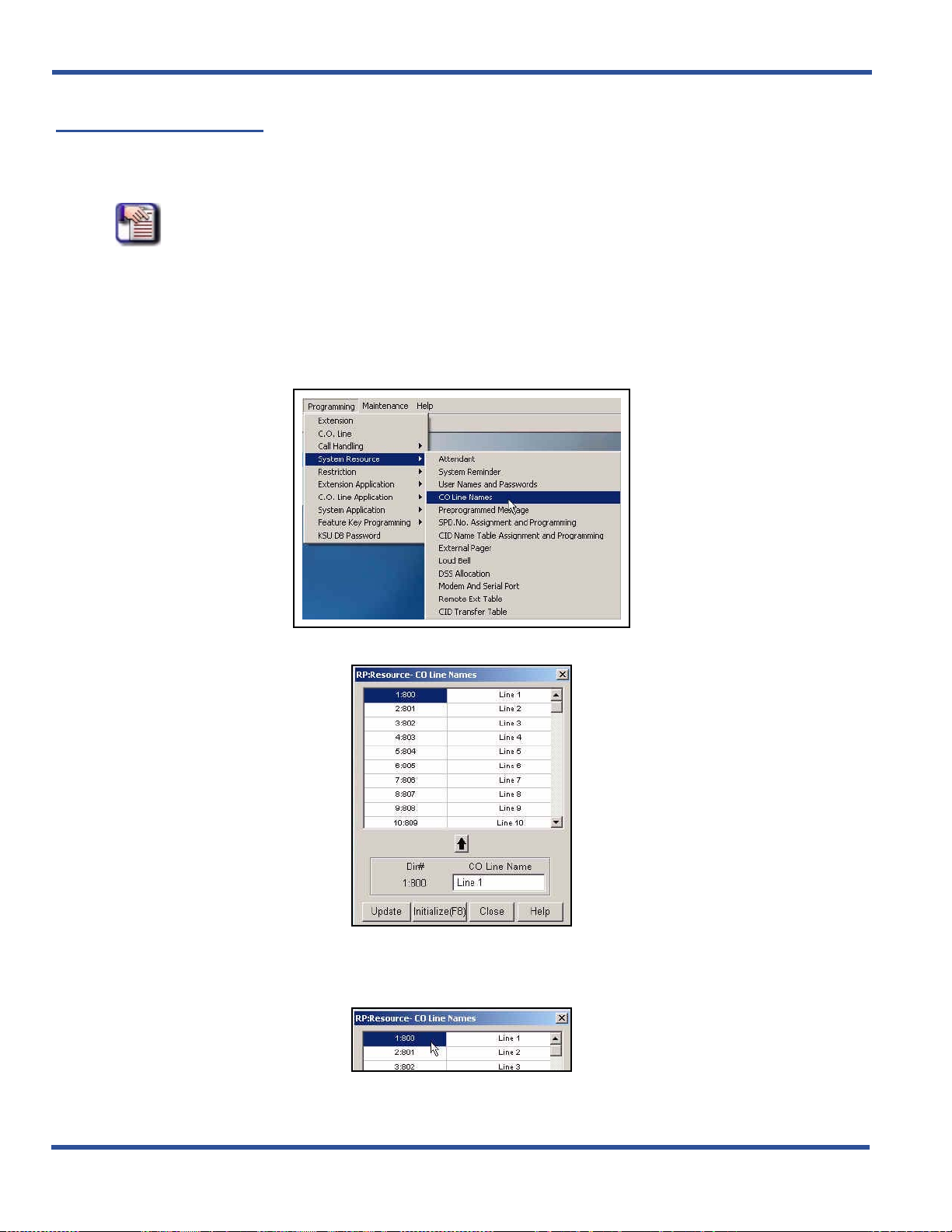
BASIC SYSTEM PROGRAMMING TASKS DX-120 Programming Manual
Naming CO Lines
The DX-120 allows you to name (or label) CO lines so you can customize the appearance of the line identifier in the
telephone display when the CO line is in use.
the intended purpose of that CO line.
NOTE
• Valid names can have up to 7 alphanumeric characters.
• The default names are "Line 1" through "Line 40," corresponding to directory
numbers 800 through 839.
• Directory Numbers 840 through 843 are reserved for future use.
NAMING CO LINES VIA PC-DBA
From the PC-DBA main screen:
This labeling can assist users when handling CO line calls by displaying
1) Go to ProgrammingXSystem ResourceXCO Line Names to display the CO Line Names screen.
In the table at the top of the screen
1) Click on (to select) the line to which you wish to assign a name.
- 58 -
Naming CO Lines via PC-DBA (continued on next page)
Page 67

DX-120 Programming Manual BASIC SYSTEM PROGRAMMING TASKS
Naming CO Lines via PC-DBA (continued)
2) Highlight the current entry in the CO Line Name field at the bottom or the CO Line names screen.
3) Enter the name you want to assign to the specified line.
4) Click above the entry line to move the newly entered name next to the specified line number.
• Use the steps shown above to assign names to other CO lines as needed.
When you are finished:
5) Click the Update button to store the settings into the database on the local disk.
6) Click the Close button to exit the current screen and return to the PC-DBA main screen.
When you have finished all programming changes:
7) Perform a SEND to copy your new database to the DX-120 switch system memory.
NAMING CO LINES THE DET
NOTE
• chg, bksp, save, one, always, del, and ack are interactive LCD button operations.
Use the three buttons below the LCD display to activate the associated operation.
• You can press Hold at any time to return to the previous level or press the volume
buttons to return to the main DB selection screen.
1) Enter Database Administration (see page 26) using the feature code Feature # * to display the password
prompt.
2) Enter the DB Admin password (see page 27).
3) Press show to display the DB Item Select screen.
4) Enter 04-06-XXX (where XXX is the number of the CO line directory you want to name).
• Valid CO line numbers range from 800 to 839.
5) Press save to display the selected CO Line Name/Label field and curr ent name for the line you specified.
6) Press chg to enter a new name/label.
7) Enter the name/label for the CO line (Use the dial pad keys and reference the lettering scheme tables).
• For additional information, see “Appendix E - Setting Up Letter Type for Using Special Characters” .
• Valid names can have up to 7 alphanumeric characters.
• The default is LINE 1 through LINE 40, corresponding to directory numb ers 800 through 839.
8) Press save when you have finished the label to save the new name/label name.
9) Press next to enter another CO line directory name.
When finished programming CO line name/labels:
10) Press the Volume button (up or down) to return to the DB Item Select screen.
OR
Exit programming (see “Exiting Database Administration” on page 27).
- 59 -
Page 68
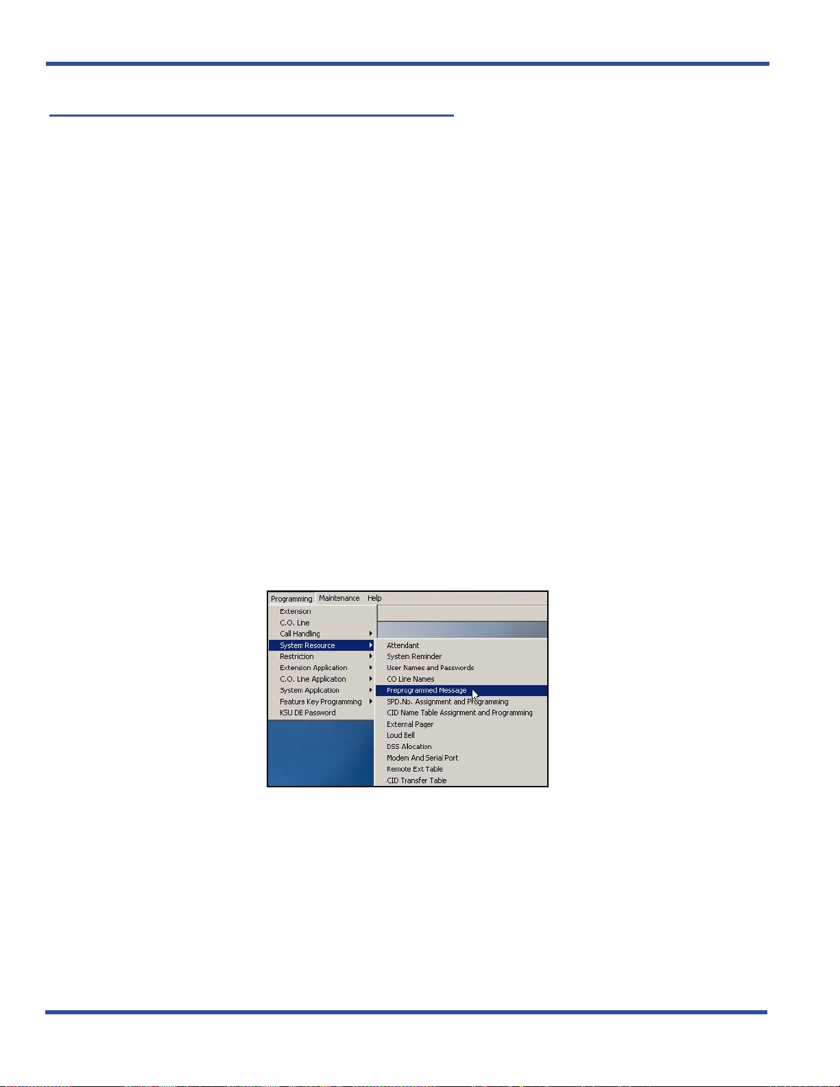
BASIC SYSTEM PROGRAMMING TASKS DX-120 Programming Manual
Setting Up Pre-Programmed Messages
The DX-120 can notify a busy or unattended DET of a call attempt via one of the DX-120 system messaging features.
At the DET display, the system shows messages waiting and provides prompts to assist the extension user in
responding to the messages.
• A message may be sent and received in several forms:
- A call me message
- A customized text message
- A pre-programmed text message (six total available)
- A voice mail message.
• The following conditions apply to messaging.
- Custom text messages can contain 16 letters/symbols maximum.
- When you enter a custom message, the system saves it for future use.
- The system allows a total of forty-eight message wait indications in the system at any one tim e.
- At DETs, the system does not remove the message waiting indication until extensio n user presses reply or
delete.
- When the system leaves a message wait indication at an extension, it flashes a slow green lamp.
- Each extension may receive more than one message waiting from various extensions.
- Multiple messages are retrieved in the order that they were left.
- Each extension can leave only one message waiting at any one extension.
SETTING UP PRE-PROGRAMMED MESSAGES VIA PC-DBA
From the PC-DBA main screen:
Setting Up Pre-Programmed Messages via PC-DBA (continued on next page)
- 60 -
Page 69
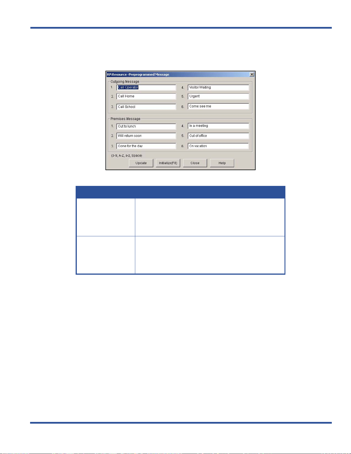
DX-120 Programming Manual BASIC SYSTEM PROGRAMMING TASKS
Setting Up Pre-Programmed Messages via PC-DBA (continued)
1) Go to ProgrammingXSystem ResourceXPreprogrammed Message to display the Preprogrammed
Message screen.
2) Enter information in the fields as described below:
In this field... enter...
• The first standard message you want to have available for
extension users when sending a message to another
Outgoing Message 1
Premises Message 1
extension.
• Specify the contents of outgoing messages 2 through 6 as
needed
• The first standard message you want to have available for
extension users to leave on their extensions when they must
leave the company premise.
• Specify the contents of premises messages 2 through 6 as
needed.
When you are finished:
3) Click the Update button to store the settings into the database on the local disk.
4) Click the Close button to exit the current screen and return to the PC-DBA main screen.
When you have finished all programming changes:
5) Perform a SEND to copy your new database to the DX-120 switch system memory.
Setting Up Pre-Programmed Messages (continued on next page)
- 61 -
Page 70

BASIC SYSTEM PROGRAMMING TASKS DX-120 Programming Manual
Setting Up Pre-Programmed Messages (continued)
SETTING UP PRE-PROGRAMMED MESSAGES VIA THE DET
Y ou can set up both Outgoing and Premise Preprogrammed me ssages (see field descriptions under step 2 on previous
page):
NOTE
• chg, bksp, save, one, always, del, and ack are interactive LCD button operations.
Use the three buttons below the LCD display to activate the associated operation.
• You can press Hold at any time to return to the previous level or press the volume
buttons to return to the main DB selection screen..
1) Enter Database Administration (see page 26) using the feature code Feature # * to display the password
prompt.
2) Enter the DB Admin password (see 27).
3) Press show to display the DB Item Select screen.
Setting Up Outgoing Messages
From the DB Item Select screen (using steps 1 to 3 above):
4) Enter 04-07-01-01.
5) Press save to display Preprogrammed Messages – Ou tg oin g (Text)
Message – 1.
6) Press next (if necessary) to advance to the next preprogrammed message.
7) Press chg to enter a new message for the selected preprogrammed message.
8) Use the chart and the dial pad keys to enter the new message. When finished:
9) Press save to store the settings.
Repeat steps above for additional messages.
10) Press the Hold button to return to the previous menu level.
OR
Press the Volume button (up or down) to return to the DB Item Selection screen.
OR
Exit programming (see “Exiting Database Administration” on page 27).
Setting Up Pre-Programmed Messages via the DET (continued on next page)
- 62 -
Page 71

DX-120 Programming Manual BASIC SYSTEM PROGRAMMING TASKS
Setting Up Pre-Programmed Messages via the DET (continued)
Setting Up Premise Messages
From the DB Item Select screen (using steps 1 to 3 on page 62):
4) Enter 04-07-02-01.
5) Press save to display Preprogrammed Messages – Premise (Text)
Message – 1.
6) Press next (if necessary) to advance to the next preprogrammed message.
7) Press chg to enter a new message for the selected preprogrammed message.
8) Use the chart and the dial pad keys to enter the new message. When finished:
9) Press save to store the settings.
Repeat steps above for additional messages.
10)Press the Hold button to return to the previous menu level.
OR
Press the Volume button (up or down) to return to the DB Item Selection screen.
OR
Exit programming (see “Exiting Database Administration” on page 27).
- 63 -
Page 72

BASIC SYSTEM PROGRAMMING TASKS DX-120 Programming Manual
Programming Speed Dial Numbers
Speed dialing allows you to store frequently dialed numbers. The system accesses these numbers for dialing by the
associated speed dial directory number (speed number location).
button for instant, one-button operation.
• There are 3 basic tasks involved in this process:
- Assign the maximum number of speed dial numbers for each tenant
- Enter all of the speed dial numbers available for each tenant group
- Allocate the number of speed dials allowed for each extension
- Enter all of the speed dial numbers for each extension
• There are 200 speed dial bins allocat ed for syste m- wid e use (locations 500-699).
• Extensions may also store up to 50 personal speed numbers in memory.
• You can program the DX-120 system to allow system speed dial numbers to override toll restriction settings (both
CO line and extension COS).
EXAMPLE
Suppose your customer has a branch office out o f state where they want to allow the
corporate extension users to call, while still prohibiting all other toll calls. In this case,
you can set up a system speed dial to allow calls to the branch office.
You can store the directory number on any feature
NOTE
It must be a system speed dial, as the system checks the toll restrictions for individual
speed dial numbers and abides by them. System speed dial numbers override toll
restrictions as long as you have System Speed Toll Check enabled - see
Disabling System Speed Toll Check” on page 252.
The default.... is...
Length of both individual and system
speed dial numbers
Range for System speed dials directory numbers 500 to 699
Range for individual speed dials dire ctory numbers 470 to 489
NOTE
You can change any of these default settings by customizing the numbering plan see
“Customizing the Numbering Plan” on page 103.
3 digits
“Enabling/
Programming Speed Dial Numbers (continued on next page)
- 64 -
Page 73

DX-120 Programming Manual BASIC SYSTEM PROGRAMMING TASKS
Programming Speed Dial Numbers (continued)
• The following conditions apply to assigning sys tem spe ed dia l num b er s:
- The DX-120 system has 1000 speed dial number memory locations that are dynamically allocated to the
system use (extensions individually via extension speed dial locations, or all extensions via system speed dial
locations).
- You can program system speed dial bins, using Attendant Administration on a DET.
- You can chain speed bins.
- You can store pauses and flashes within the speed dial number . Chaining , p auses, and flashes e ach occupy
one character position.
- If you access an empty bin the system displays a message that reads: "SPEED NO. EMPTY."
NOTE
You can pro gram individual sp eed dial numb er s at the ind ivid ual extensio n, or a cross
several extensions using PC-DBA. If you use the DET to set up your speed dials, you
will have to program the speed dials at each extension; you cannot program individual
speed dial numbers globally using the DET.
PROGRAMMING SPEED DIAL NUMBERS VIA PC-DBA
From the PC-DBA main screen:
Programming Speed Dial Numbers via PC-DBA (continued on next page)
- 65 -
Page 74
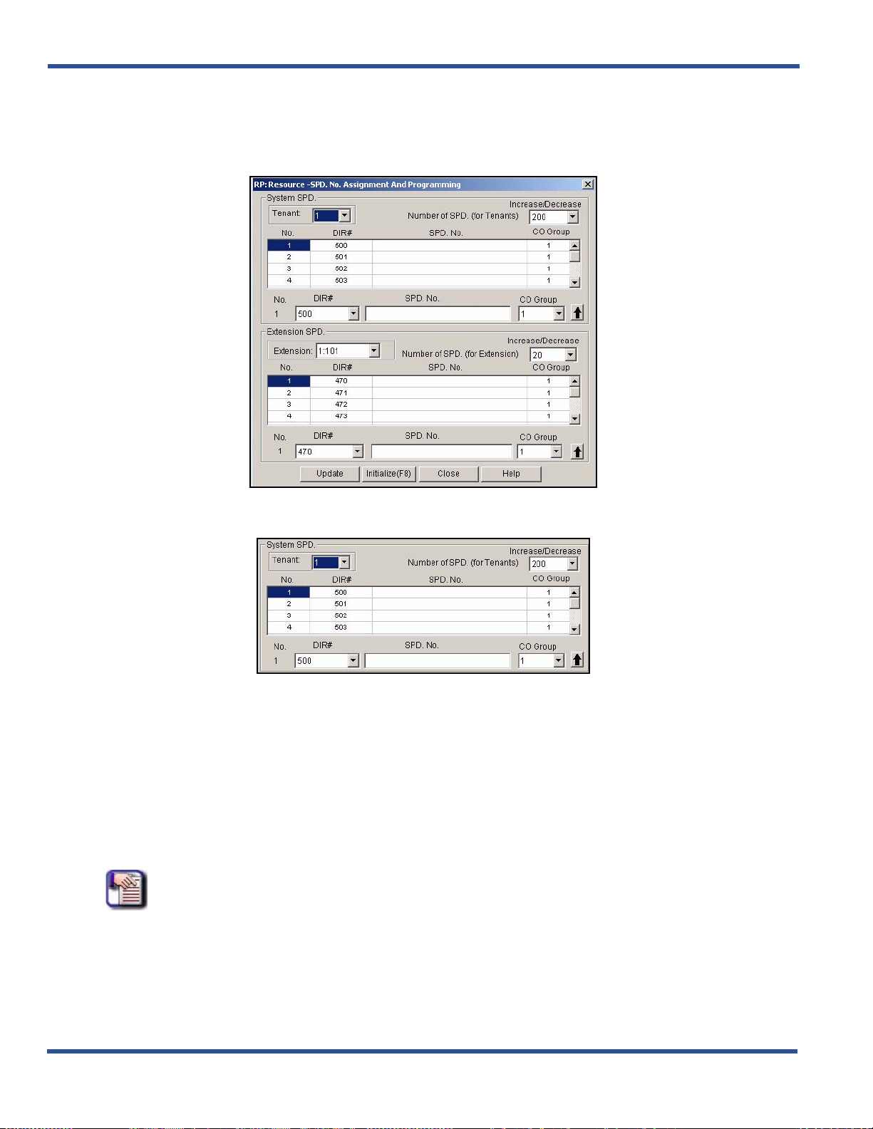
BASIC SYSTEM PROGRAMMING TASKS DX-120 Programming Manual
Programming Speed Dial Numbers via PC-DBA (continued)
1) Go to ProgrammingXSystem ResourceXSPD.No.Assignment and Programming to display the
SPD.No.Assignment and Programming screen.
In the System SPD area:
2) Select the Tenant group you wish to program.
3) Select the number of speed dial numbers you want to assign to the currently selected tenant group from
the Number of SPD (for Tenants) field.
• When you first select a tenant group (see step 2 above), the field displays the number of speed dial
numbers currently assigned to each tenant group.
room) the number of speed dials available to the tenant group.
• The valid range is 0 through 1000, in multiples of 50.
• The defaults are 200 for tenant group 1, and 0 for tenant gr oups 2 and 3.
• Assign the number of speed dials for each tenant group as necessary by following the steps above.
NOTE
There is a maximum number of speed dials available for the system as a whole. If
you cannot assign any to tenant groups 2 and 3, decrease the number available to
tenant group 1, then try again.
You can decrease or increase (if there is sufficient
Programming Speed Dial Numbers via PC-DBA (continued on next page)
- 66 -
Page 75

DX-120 Programming Manual BASIC SYSTEM PROGRAMMING TASKS
Programming Speed Dial Numbers via PC-DBA (continued)
Once you have assigned a maximum number of system speed dials to each tenant group:
4) Click on the desired speed dial the in the System SPD scroll list.
• The appropriate line will also be highlighted in the scroll list above) from the DIR # field.
5) Click in the SPD. No. field and type the number you wish to associate with this speed dial.
• Use special characters as required.
- Pause = P
- Flash = / (forward slash)
- Speed Numbering Chaining = @ + next speed number (500-699).
6) Enter the group number you want associated with this speed dial number.
• Valid choices are from 1 to 8.
• The default is 1.
7) Click to move the number into the scroll list.
• The default for all system speed dials is blank.
• Use this same procedure to program as many system speed dial numbers as needed (up to the limit
you assigned to each tenant group).
Once you have programmed all of the speed dial numbers, go to the Extension SPD area:
8) Select the Extension you wish to program.
9) Select the number of speed dial numbers you wa nt to allow for the currently selected extension from the
Number of SPD. (for Extension) field.
• The range of allowable speed dials per extension is 0 to 50, in increments of 10. The default for
extensions 101-140 is 20.
• The default for all others is 0.
• Use this same procedure to program to allocate the appropriate number of speed dials for each
Extension.
NOTE
If the system will not allow you to assign speed dials to an extension, decrease the
number assigned to one or more of the other extensions, then try again.
Programming Speed Dial Numbers via PC-DBA (continued on next page)
- 67 -
Page 76

BASIC SYSTEM PROGRAMMING TASKS DX-120 Programming Manual
Programming Speed Dial Numbers via PC-DBA (continued)
Once you have assigned a maximum number of system speed dials to each extension:
10) Click on the desired speed dial the in the System SPD scroll list.
• The appropriate line will also be highlighted in the scroll list above) from the DIR # field.
11) Click in the SPD. No. field and type the number you wish to associate with this speed dial.
• Use special characters as required.
- Pause = P
- Flash = / (forward slash)
- Speed Numbering Chaining = @ + next speed number (500-699).
12) Enter the group number you want associated with this speed dial number.
• Valid choices are from 1 to 8.
• The default is 1.
13) Click to move the number into the scroll list.
• The default for all system speed dials is blank.
• Use this same procedure to program as many system speed dial numbers as needed (up to the limit
you assigned for each extension).
When you are finished:
14) Click the Update button to store the settings into the database on the local disk.
15) Click the Close button to exit the current screen and return to the PC-DBA main screen.
When you have finished all programming changes:
16) Perform a SEND to copy your new database to the DX-120 switch system memory.
Programming Speed Dial Numbers (continued on next page)
- 68 -
Page 77

DX-120 Programming Manual BASIC SYSTEM PROGRAMMING TASKS
Programming Speed Dial Numbers (continued)
PROGRAMMING SPEED DIAL NUMBERS VIA THE DET
NOTE
• chg, bksp, save, one, always, del, and ack are interactive LCD button operations.
Use the three buttons below the LCD display to activate the associated operation.
• You cannot program individual speed dial numbers globally using the DET. If you
wish to do this, you must use PC-DBA.
1) Enter Database Administration (see page 26) using the feature code Feature # * to display the password
prompt.
2) Enter the DB Admin password (see page 27).
3) Press show to display the DB Item Select screen.
Programming the Number of Speed Dial Numbers Allowed on an Extension:
This process allows you to program the number of speed dial numbers allowed on an individual extension.
4) Enter 04-08.
5) Press save to display the SPD No. Assignment screen.
6) Press show to advance to the Assignment for Individual Speed Dial numbers screen.
7) Press show to change an extension’s speed numbers assignment.
8) Enter the extension number you want to set.
9) Press show to advance to the Increase screen for this extension.
10) Press chg to increase the assigned speed dial numbers for this extension.
• The range of allowable speed dials is 0 to 50.
• The default for extensions 101-140 is 20.
• The default for all others is 0.
OR
Press next to advance to the Decrease screen for this extension.
11) Press chg to decrease the assigned speed dial numbers for this extension.
12) Press next if you want to change another extension number in the same tenant group.
• Repeat above steps if you want to change another extension number in the same manner.
OR
Press the Hold button twice to display the Individual Speed Dial Number screen (see step 6 above).
• You can then press next to display the system speed dial list, then go to step 6 in “Programming the
Number of System Speed Dial Numbers Allowed per Tenant:” on page 70.
OR
Press the volume UP button to return to the DB Item Selection screen.
OR
Exit programming (see “Exiting Database Administration” on page 27).
Programming Speed Dial Numbers via the DET (continued on next page)
- 69 -
Page 78

BASIC SYSTEM PROGRAMMING TASKS DX-120 Programming Manual
Programming Speed Dial Numbers via the DET (continued)
Programming the Number of System Speed Dial Numbers Allowed per Tenant:
Use this process to program speed dial numbers for use by any extension user on the DX-120 system.
From the DB Item Select screen (see steps 1 through 3 on page 69):
4) Enter 04-08-02.
5) Press save to display the Assignment for System Speed Dial numbers screen.
6) Press show.
7) Enter the tenant group number you want to change (usually tenant group 1).
8) Press show to advance to the Increase screen for this Tenant Group System Speed List.
9) Press chg to increase the number of allocated speed dial numbers (in increments of 50).
• The range of allowable speed dials is 0 to 1000.
• The default is 200.
OR
Press next to advance to the Decrease screen for this Tenant Group System Speed List.
10) Press chg to decrease the number of allocated speed dial numbers (in increments of 50).
11) Press next to enter a new tenant group and continue programming.
12) Press the Hold button to return to the previous menu level.
OR
Press the Volume button (up or down) to return to the DB Item Selection screen.
OR
Exit programming (see “Exiting Database Administration” on page 27).
Program the System Speed Numbers:
From the DB Item Select screen (see steps 1 through 3 on page 69):
4) Enter 04-09-X (where X represents the tenant group: 1~3).
5) Press save to display the the system speed dial entry point for the tenant group you specified.
6) Enter the speed dial number to program (500-699).
7) Press show to display the current stored number.
8) Press chg to change this stored number.
9) Enter the new telephone number (using special characters as required).
- Pause = Feature 7 0
- Flash = Feature 3
- Pulse-To-Tone Conversion = *
- Speed Numbering Chaining = Feature # + next speed number (500~699).
Programming Speed Dial Numbers via the DET (continued on next page)
- 70 -
Page 79

DX-120 Programming Manual BASIC SYSTEM PROGRAMMING TASKS
Programming Speed Dial Numbers via the DET (continued)
10) Press save to display the speed dial number and the new contents.
11) Press next.
12) Press chg to select the C.O. Group you want to associate with this speed dial.
• The default is 1.
• Use the steps above to program other system speed dials as needed.
13) Press next to complete the setting.
• Repeat the steps above for each tenant group for which you want to program speed dial numbers.
When you are finished programming the system speed dials number s:
14) Press the Hold button to return to the previous menu level.
OR
Press the Volume button (up or down) to return to the DB Item Selection screen.
OR
Exit programming (see “Exiting Database Administration” on page 27).
- 71 -
Page 80

BASIC SYSTEM PROGRAMMING TASKS DX-120 Programming Manual
Programming CID Names and Assignments Table
This table stores information used by the DX-120 when dialing outgoing calls. Such information includes any special
entries used when dialing (e.g., local area codes, country and international countr y codes), as well as any names
displayed during those calls. The system stores caller identification information for 100 calls in this call table. While
reviewing the calls, you will have the option to dial the number, obtain more information for the particular call, or delete
the call.
• The following conditions apply when programming the caller ID table:
- You must properly program the local area code and long distance prefix so the system can accurately re-dial
the CID number from the caller ID table.
- If no name is delivered from the telephone company, the system displays the number only.
- Any digital speaker ph one user can review the caller ID t able if the attendant p assword is known, but the tab le
can be reviewed by only one telephone at a time.
- You can exit the caller ID call table mode at any time.
• When programming the caller ID table, enter the following:
- International prefix (typically not required in the USA or Canada).
- Country code (typically not required in the USA or Canada).
- Long distance prefix (usually 1).
- Local area codes (enter them as the prefix if the local phone company uses 10 digit dialing).
HINT
See “Programming Caller ID Codes and Local Calling Areas” on page 264.
PROGRAMMING CID NAMES AND ASSIGNMENTS TABLE VIA PC-DBA
From the PC-DBA main screen:
Programming CID Names and Assignments Table via PC-DBA (continued on next page)
- 72 -
Page 81
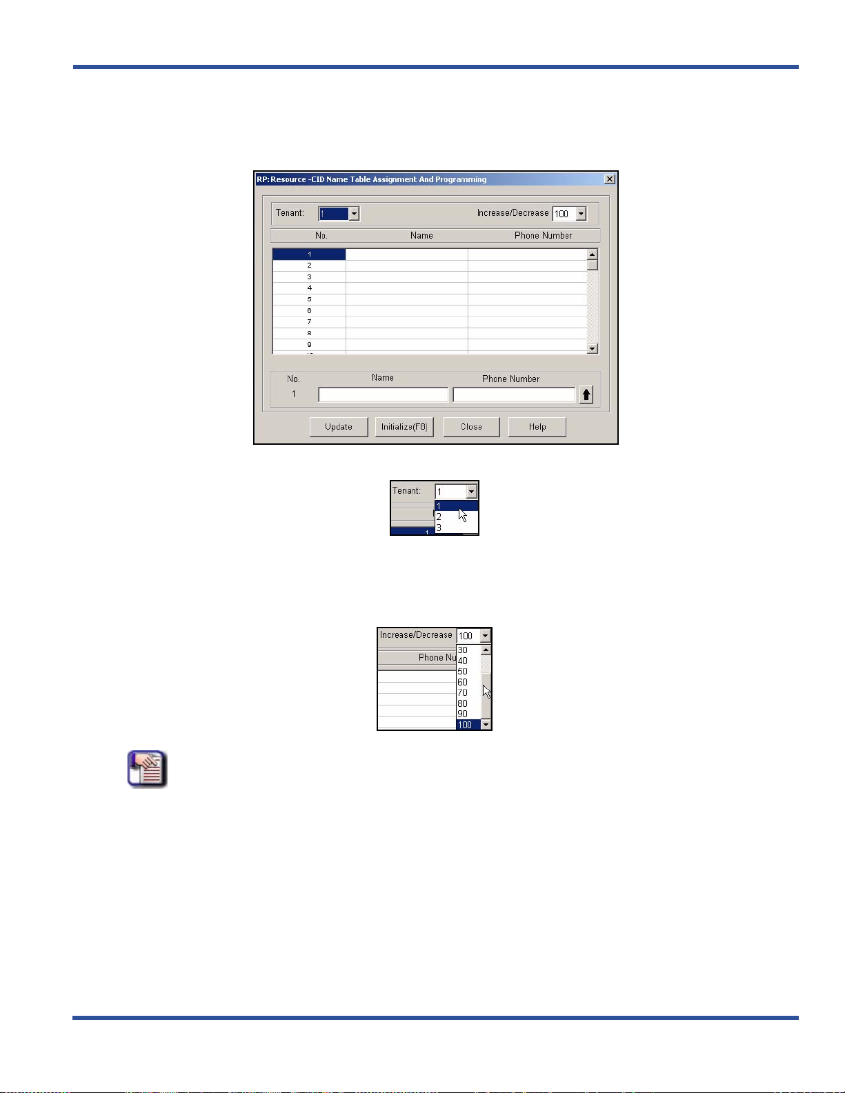
DX-120 Programming Manual BASIC SYSTEM PROGRAMMING TASKS
Programming CID Names and Assignments Table via PC-DBA (continued)
1) Go to ProgrammingXSystem ResourceXCID Name Table Assignment and Programming to display the
CID Name Table Assignment and Programming screen.
2) Select the tenant for which you want to program CID information.
3) Decrease or increase (if there is sufficient room) the number of caller ID names in the table as needed
(and if there is sufficient room).
• The range is 0 to 100, selectable in increments of 10.
• The default is 100 for tenant group 1, and 0 for tenant groups 2 and 3.
NOTE
• 100 is the maximum number of caller ID entries available for the system as a
whole.
• To assign some of them to tenant groups 2 and 3, you must decrease the number
available to tenant group 1.
Programming CID Names and Assignments Table via PC-DBA (continued on next page)
- 73 -
Page 82

BASIC SYSTEM PROGRAMMING TASKS DX-120 Programming Manual
Programming CID Names and Assignments Table via PC-DBA (continued)
4) Select a line in the scroll list just below the Tenant and Increase/Decrease fields.
5) Enter the name you wish to associate with a CID entry.
6) Enter the corresponding telephone number in Phone Number field for the name you entered in the
previous step.
7) Click to move the number into the scroll list.
• Program other caller IDs as needed using the steps above.
When all assignments have been made:
8) Click the Update button to enter and save your settings into the database on your local disk.
9) Click the Close button to exit the current screen and return to the PC-DBA main screen.
Once all database changes have been completed:
10)Perform a SEND to copy your new database to the DX-120 switch system memory.
HINT
Also see“Programming CID Names and Assignments Table” on page 72.
Programming CID Names and Assignments Table (continued on next page)
- 74 -
Page 83

DX-120 Programming Manual BASIC SYSTEM PROGRAMMING TASKS
Programming CID Names and Assignments Table (continued)
PROGRAMMING CID NAMES AND ASSIGNMENTS TABLE VIA THE DET
NOTE
• chg, bksp, save, one, always, del, and ack are interactive LCD button operations.
Use the three buttons below the LCD display to activate the associated operation.
• You can press Hold at any time to return to the previous level or press the volume
buttons to return to the main DB selection screen.
1) Enter Database Administration (see page 26) using the feature code Feature # * to display the password
prompt.
2) Enter the DB Admin password (see page 27).
3) Press show to display the DB Item Select screen.
4) Enter 04-10 to enter CID Names and Assignments Table programming.
5) Press save.
6) Press show to advance to the Assignment for CID Name Table screen.
7) Select the tenant number.
• Valid entries are 1 to 3.
• The default is 1.
8) Press show.
9) Decrease or increase (if there is sufficient room) the number of caller ID names in the table.
10) Enter 04-10-1-01.
11) Press chg if you want to increase the number of Caller ID numbers allowed for tenant group 1.
• The system then automatically increases the amount of caller ID names allowed, counting by 10.
• The range of allowable speed dials is 0 to 100.
• The default is 100.
OR
Press next to display the Decrease screen (now go to step 12).
OR
Enter 04-10-1-02 (now go to step 12).
12) Press chg to decrease the number of Caller ID numbers allowed for tenant group 1.
• The system then automatically decreases the amount of caller ID n ames allowe d, in increment s of 10.
13) Press next to display the Tenant screen.
14) Press chg until the next tenant number you want to program appears: 1~3.
15) Press show to display the current Caller ID number setting for that tenant.
OR
Enter 04-10-2-01.
16) Press save if you want to increase the number of Caller ID numbers allowed for tenant group 2.
OR
Enter 04-10-2-02.
17) Press save if you want to decrease the number of Caller ID numbers allowed for tenant group 2.
Programming CID Names and Assignments Table via the DET (continued on next page)
- 75 -
Page 84

BASIC SYSTEM PROGRAMMING TASKS DX-120 Programming Manual
Programming CID Names and Assignments Table via the DET (continued)
18) Enter 04-10-3-01.
19) Press save if you want to increase the number of Caller ID numbers allowed for tenant group 3.
OR
Enter 04-10-3-02.
20) Press save if you want to decrease the number of Caller ID numbers allowed for tenant group 3.
21) Press the Hold button to return to the previous menu level.
OR
22) Press the Volume button (up or down) to return to the DB Item Selection screen.
OR
Exit programming (see “Exiting Database Administration” on page 27).
- 76 -
Page 85

BASIC SYSTEM PROGRAMMING TASKS
DX-120 Programming Manual
DX-120 Programming Manual BASIC SYSTEM PROGRAMMING TASKS
Assigning External Page
The system provides external one-way, dedicated paging access to a paging amplifier or multi-zone oneway page controller. The external paging zone may be accessed individually, or with all eight internal paging
zones as an all-call page.
HINT
To set up individual extensions for pager use, see “Assigning Extensions to Paging
Groups” on page 397.
ASSIGNING EXTERNAL PAGING VIA PC-DBA
From the PC-DBA main screen:
1) Go to ProgrammingXSystem ResourceXExternal Page to display the External Page screen.
2) Select the Page Port to which you want to assign groups.
Assigning External Page ID via PC-DBA (continued on next page)
- 77 -
Page 86

BASIC SYSTEM PROGRAMMING TASKS DX-120 Programming Manual
Assigning External Page ID via PC-DBA (continued)
3) Select the groups you want to assign to the selected port.
• A checked box indicates that the group is assigned to the cu rrently selected port. If a box is unchecked,
that group is unassigned.
When all assignments have been made to the current port:
4) Click the Update button to enter and save your settings into the database on your local disk.
• Repeat the above steps for other page ports.
When all assignments have been made to all ports (as needed):
5) Click the Close button to exit the current screen and return to the PC-DBA main screen.
Once all database changes have been completed:
6) Perform a SEND to copy your new database to the DX-120 switch system memory.
ASSIGNING EXTERNAL PAGING VIA THE DET
NOTE
• chg, bksp, save, one, always, del, and ack are interactive LCD button operations.
Use the three buttons below the LCD display to activate the associated operation.
• You can press Hold at any time to return to the previous level or press the volume
buttons to return to the main DB selection screen.
1) Enter Database Administration (see page 26) using the feature code Feature # * to display the password
prompt.
2) Enter the DB Admin password (see page 27).
3) Press show to display the DB Item Select screen.
Specify the Paging Group
You need to select the paging group to be Used by the tenant group for the external paging port
From the DB Item Select screen (follow steps 1 through 3 above)
4) Enter 04-12.
5) Press save to display the External Pager.
6) Press show to display the Pager ID.
• The only valid choice is 1.
7) Press 1 to confirm.
Assigning External Page ID via the DET (continued on next page)
- 78 -
Page 87

DX-120 Programming Manual BASIC SYSTEM PROGRAMMING TASKS
Assigning External Page ID via the DET (continued)
8) Press show to display the tenant group.
9) Press next to display the first paging group.
10) Press chg to select (and apply) the currently displayed paging group.
11) Press next to display the next paging group.
• Repeat steps 9 and 10 until all paging groups are selected as necessary.
12) Press the Hold button to return to the previous menu level.
OR
Press the Volume button (up or down) to return to the DB Item Selection screen.
OR
Exit programming (see “Exiting Database Administration” on page 27).
Specify the Number of Digits for the Extension
You need to specify the number of digits for the extension you will use to access the external pager:
From the DB Item Select screen (follow steps 1 through 3 on page 78)
4) Enter 08-09-11-01.
5) Press save.
6) Press chg to select 1 - 4.
7) Press save.
• The default is 3.
8) Press the Hold button to return to the previous menu level.
OR
Press the Volume button (up or down) to return to the DB Item Selection screen.
OR
Exit programming (see “Exiting Database Administration” on page 27).
Program the External Page Directory Number Leading 1, 2 or 3
9) Enter 08-09-11-02.
10) Press save.
11) Press chg.
12) Enter the dir ec to ry nu m ber yo u wan t to use to acce ss th e ex ter n al pager, and then press save.
• Valid directory numbers include any available, non-conflicting directory number.
• The default is 777.
13) Press the Hold button to return to the previous menu level.
OR
Press the Volume button (up or down) to return to the DB Item Selection screen.
OR
Exit programming (see “Exiting Database Administration” on page 27).
- 79 -
Page 88

BASIC SYSTEM PROGRAMMING TASKS DX-120 Programming Manual
Establishing Loud Bell Settings
If the system is installed in high noise environments (e.g., where machinery is being used, shipping/receiving areas,
etc.), there is often a requirement to equip a loud (high-gain) ringing device.
ESTABLISHING LOUD BELL SETTINGS VIA PC-DBA
From the PC-DBA main screen:
1) Go to ProgrammingXSystem ResourceXLoud Bell to display the Loud Bell screen.
Establishing Loud Bell Settings via PC-DBA (continued on next page)
- 80 -
Page 89

DX-120 Programming Manual BASIC SYSTEM PROGRAMMING TASKS
Establishing Loud Bell Settings via PC-DBA (continued)
2) Click the down arrow to the right of the Application field and select one of the following:
- L.B. (loud bell) - this is the default setting
- M.S.1 (music source 1)
- M.S.2 (music source 2)
- E.P. (external page)
- DIR (loud bell control -- users can dial loud bell number to close relay until they hang up)
3) Click the boxes below the Application field to put a check mark next to each CO line group for which you
wish to enable the loud bell.
• A checked box indicates that the CO line group is assigned to the currently selected application. If a
box is unchecked, that group is unassigned.
When all assignments have been made:
4) Click the Update button to enter and save your settings into the database on your local disk.
5) Click the Close button to exit the current screen and return to the PC-DBA main screen.
Once all database changes have been completed:
6) Perform a SEND to copy your new database to the DX-120 switch system memory.
Establishing Loud Bell Settings via PC-DBA (continued on next page)
- 81 -
Page 90

BASIC SYSTEM PROGRAMMING TASKS DX-120 Programming Manual
Establishing Loud Bell Settings (continued)
ESTABLISHING LOUD BELL SETTINGS VIA THE DET
NOTE
• chg, bksp, save, one, always, del, and ack are interactive LCD button operations.
Use the three buttons below the LCD display to activate the associated operation.
• You can press Hold at any time to return to the previous level or press the volume
buttons to return to the main DB selection screen.
1) Enter Database Administration (see page 26) using the feature code Feature # * to display the password
prompt.
2) Enter the DB Admin password (see page 27).
3) Press show to display the DB Item Select screen.
4) Enter 04-13-1.
5) Press save to advance to you to the Loud Bell – Application programming field.
6) Press chg to select L.B., M.S.1, M.S.2, or E.P.
- L.B. (loud bell) - this is the default setting
- M.S.1 (music source 1)
- M.S.2 (music source 2)
- E.P. (external page)
- DIR (loud bell control -- users can dial loud bell number to close relay until they hang up)
7) Press next to specify which CO line groups you want to use the ancillary device.
8) Press chg to activate/deactivate the device for each CO line group.
9) Press the Hold button to return to the previous menu level.
OR
Press the Volume button (up or down) to return to the DB Item Selection screen.
OR
Exit programming (see “Exiting Database Administration” on page 27).
- 82 -
Page 91

DX-120 Programming Manual BASIC SYSTEM PROGRAMMING TASKS
Establishing Music Sources
CAUTION!
It is the your responsibility to adhere to all applicable copy¦right laws and any
other music source restrictions.
• The system provides two dedicated 3.5 millimeter phono-jack type inputs so you can connect two external music
sources. The external music source may be a radio tuner, tape deck, CD player, message on hold, or other
source.
• You must connect an external music source to the KSU1-CPM Music1 or KSU1-CPM Music2 ports for the music
on hold and background music features to operate.
• Users can listen to these music sources at digital speakerph one extensions by using the backgrou nd music codes
(771/772). Also, any caller placed on hold will hear the music source you program for that CO line (sources are
programmable on a per-CO line basis). You will assign music sources when you program the CO lines (see
“Section 5 - Programming C.O. Lines” on page 115). At that time, you will specify either MC1 or MC2 as the music
source for each CO line.
HINT
Also see “Setting the Day and Evening Class of Services (COS) and Music On Hold
(MOH) Source” on page 121
ESTABLISHING MUSIC SOURCES VIA PC-DBA
From the PC-DBA main screen:
Establishing Music Sources via PC-DBA (continued on next page)
- 83 -
Page 92

BASIC SYSTEM PROGRAMMING TASKS DX-120 Programming Manual
Establishing Music Sources via PC-DBA (continued)
1) Go to ProgrammingXSystem ApplicationXNumbering Plan to display the Numbering Plan (Part 1)
screen.
2) Click More... to display the Numbering Plan (Part 2) screen.
Establishing Music Sources via PC-DBA (continued on next page)
- 84 -
Page 93

DX-120 Programming Manual BASIC SYSTEM PROGRAMMING TASKS
Establishing Music Sources via PC-DBA (continued)
In the Music Source fields in the center left area of the screen:
3) Specify the appropriate information in the fields as described below:
For this field... Specify...
the number of digits in the extension you will use to access the
music sources.
Length
Leading 1
• To do this, you can click the down arrow to the right of the
Length field and select 1 - 4.
• The default is 3.
the directory number of the extension you want to use for the first
music source in the Leading 1 field.
• Valid directory numbers include any available, non-conflicting
directory number.
• The default is 771.
the directory number you want to use for the second music
source in the Leading 2 field.
Leading 2
Leading 3
• Valid directory numbers include any available, non-conflicting
directory number.
• The default is 772.
• This field is not used and is always blank.
When you are finished:
4) Click the Update button to store the settings into the database on the local disk.
5) Click the Close button to exit the current screen and return to the PC-DBA main screen.
When you have finished all programming changes:
6) Perform a SEND to copy your new database to the DX-120 switch system memory.
- 85 -
Establishing Music Sources (continued on next page)
Page 94

BASIC SYSTEM PROGRAMMING TASKS DX-120 Programming Manual
Establishing Music Sources (continued)
ESTABLISHING MUSIC SOURCES VIA THE DET
NOTE
• chg, bksp, save, one, always, del, and ack are interactive LCD button operations.
Use the three buttons below the LCD display to activate the associated operation.
• You can press Hold at any time to return to the previous level or press the volume
buttons to return to the main DB selection screen.
1) Enter Database Administration (see page 26) using the feature code Feature # * to display the password
prompt.
2) Enter the DB Admin password (see page 27).
3) Press show to display the DB Item Select screen.
Program the Music Directory Number Length
(the number of digits in the extension you will use to access the music sources)
4) Enter 08-09-09-01.
5) Press save.
6) Press chg to select the number of digits in the extension you will use to access the music sources.
• Valid selections are 1, 2, 3, or 4.
• The default is 3.
7) Press save to store the setting.
8) Press the Volume button (up or down) to return to the DB Item Selection screen.
Program the directory number of the extension you want to use for the first music source
9) Enter 08-09-09-02.
10) Press save.
11) Press chg.
12) Enter the appropriate directory number.
• Valid directory numbers include any available, non-conflicting directory number.
• The default is 771.
13) Press next.
• Repeat steps 10 through 13 for each of the remaining music sources (i.e., Leading 2 and 3) you want to
program.
- 86 -
Page 95

DX-120 Programming Manual BASIC SYSTEM PROGRAMMING TASKS
Assigning Ancillary Devices Loud Bell, External Page, or Music on Hold
There is often a requirement to control ancillary devices via the telephone system. The DX-120 system provides one
dry contact closure (standard) for interface of the various dev ic es .
CAUTION
It is important to adhere to the electrical requirements of this contact. The
contact closure is rated at 24vdc, 1Amp.
You can assign the contact closure to one of the following four uses.
• Loud Bell Control
Loud bell is used to activate the Loud Bell Feature, then specify which CO Groups to which the loud bell should
be applied.
EXAMPLE
When the phone rings in the warehouse, we wa nt the loud b ell set up to ring so that if
someone is standing just outside or in the back of the warehouse, they will hear the
phone ringing.
- If the system is installed in high noise environments, there is often a requirement to equip a loud (high-gain)
ringing device.
- Using the contact in this way provides for control of an optional, ancillary loud ringing device. The device is
connected to the contact as a trigger.
- When ringing occurs on CO lines in CO line groups d esignated for loud bell, the cont act closure operates a nd
controls the connected device.
• External Page Control
This feature is used in conjunction with loud speaker so that announcements can be made over a P.A. system.
- The contact may also be programmed to control external paging apparatus.
- When programmed in this manner, the contact closure operates whenever the external paging port is
activated.
• Music Source Control
MS1 or MS2 is used if you want to use the BELL CONTACT (hardware set up) as an off/on switch (i.e., this
setting will also need the Loud Bell contact to be used).
EXAMPLE:
We have a Classical Music CD loaded in the CD player which is being used as Music
Source 1. But... we don't want the CD to be played constantly (as that would wear
out the CD quickly). Instead, we only want the CD to play when th e system detect s a
call on hold.
- The contact may also be programmed to co ntrol Message On Hold devices.
- In this mode of operation the contact closure operates whenever CO lines are placed on hold.
- This function can reduce wear on electromechan ical devices that provide the message on hold function.
Assigning Ancillary Devices (continued on next page)
- 87 -
Page 96

BASIC SYSTEM PROGRAMMING TASKS DX-120 Programming Manual
Assigning Ancillary Devices (continued)
• DIR
This feature is used in conjunction with a bell or buzzer and acts as a gate/door control.
EXAMPLE
You might wan t to set this feature up in a warehouse so that when a truck pulls up to
the gate to make a delivery, he calls the warehouse manager who can then dial 779
to open the gate for the truck to drive through to get back to the loading dock of the
warehouse.
OR
When there is no receptionist, a phone is left in the lobby. When a visitor arrives, they
use the lobby phone to dial the extension of the employee they are visiting. That
employee can then dial 779 (or other specified number) to open the locked door,
allowing the visitor to enter beyond the lobby.
HARDWARE SETUP (I.E., USING THE CONTACTS ON THE CPM AS MENTIONED ABOVE)
• Music Sources 1 and 2 Contacts allow for music (or something else) to be played while calls are on hold - but
must also be set up in PC-DBA or by DET.
• External Pager Contact provides the ability to dial a number from an extension so that a page can be sent to
selected paging zones (aka an announcement over a speaker).
• Loud Bell Contact provides the ability to set the system up so that in certain (perhaps noisy) areas in a building,
when the phone rings, it will activate a loud bell and can also be used as an on/off switch for Music On Hold and
External Page.
IMPORTANT!
In addition to making the correct contact setting, you must also program the
features above in the system software - see below.
SOFTWARE SETUP
Once you make the hardware (contact) setup, you must program the features in the program software. The settings
are made in the Loud Bell feature - see
“Establishing Loud Bell Settings” on page 80.
- 88 -
Page 97

DX-120 Programming Manual BASIC SYSTEM PROGRAMMING TASKS
Assigning the DSS Port/Owner
The Attendant/Extension DSS console is a self-contained digit al terminal that inter acts with a pr edetermined DET. The
console has 64 programmable buttons that can be used for ea sy access to the DX-120 system’s many CO lines,
extensions, and features.
All sixty-four (64) buttons on the DSS console have dual colored LEDs that allow status mo nitoring of system resources
such as CO lines and extensions.
Although usually considered to be an attendant feature benefit, the DSS console can be assigned to any DX-12 0 DET.
You can add a maximum of 12 sixty-four-button Attendant/Extension consoles to the system. Each requires its own
dedicated digital port, and therefore reduces the number of DETs that you can connect to the system on a one-to-one
basis.
• The following conditions apply when assigning DSS port owners.
- Each DSS console has 64 dual-color LED buttons
- Each DSS console requires its own dedicated cable pair from the KSU.
- You can assign up to 12 DSS consoles in the DX-120 system.
- You can assign to any DET a maximum of four Attendant/extension DSS consoles.
NOTE
Each DSS is “mapped” with a default button arrangement.
ASSIGNING THE DSS PORT/OWNER VIA PC-DBA
From the PC-DBA main screen:
Assigning the DSS Port/Owner via PC-DBA (continued on next page)
- 89 -
Page 98

BASIC SYSTEM PROGRAMMING TASKS DX-120 Programming Manual
Assigning the DSS Port/Owner via PC-DBA (continued)
1) Go to ProgrammingXSystem ResourceXDSS Allocation display the DSS Allocation screen.
2) Select a line in the scroll list at the top of the screen.
3) Select the directory number of the digital port to which the DSS Console is connected from the DIR NO
field.
• Valid port directory numbers include any available, non-conflicting port directory number.
• The default is blank.
Assigning the DSS Port/Owner via PC-DBA (continued on next page)
- 90 -
Page 99

DX-120 Programming Manual BASIC SYSTEM PROGRAMMING TASKS
Assigning the DSS Port/Owner via PC-DBA (continued)
4) Select the number of the extension with which this DSS will operate from DSS Owner field.
• Valid extension numbers include any available, non-conflicting extension number.
• The default is blank.
5) Click to the right of the entry line to place your entries in the scroll list.
• Program other ports as needed using the steps above.
6) Click the Update button to enter and save your settings into the database on your local disk.
When all assignments have been made:
7) Click the Close button to exit the current screen and return to the PC-DBA main screen.
Once all database changes have been completed:
8) Perform a SEND to copy your new database to the DX-120 switch system memory.
- 91 -
Page 100

BASIC SYSTEM PROGRAMMING TASKS DX-120 Programming Manual
PROGRAMMING USING THE DET
NOTE
• chg, bksp, save, one, always, del, and ack are interactive LCD button operations.
Use the three buttons below the LCD display to activate the associated operation.
• You can press Hold at any time to return to the previous level or press the volume
buttons to return to the main DB selection screen.
1) Enter Database Administration (see page 26) using the feature code Feature # * to display the password
prompt.
2) Enter the DB Admin password (see page 27).
3) Press show to display the DB Item Select screen.
4) Enter 04-14-01-01 to program the owner of DSS Console #1.
5) Press save to display the current programming of the DSS Console #1 owner.
To change the designated DSS console owner press chg
6) Enter the extension number to be assigned as the DSS Console owner.
NOTE
Only valid (equipment installed) extension directory numbers can be assigned as
DSS Console Owners.
7) Press save to store the settings.
8) Press next to display the current directory of the DSS Console (e.g., “NULL” if empty).
9) Press chg to enter the new DSS Console directory number (the extension number of the digital port to
which the DSS Console is connected).
10) Press save to store the settings.
11) Press next to display a prompt for the next DSS Console # to be programmed.
• Valid entries are 1-12.
12) Enter the number of the next DSS Console to program.
OR
Press the Hold button to return to the previous programming menu fo r o ther pr ogram ming re quir ements.
OR
13) Press the SPK button twice to exit programming mode.
- 92 -
 Loading...