

Page 1

HoElephontZ
User’s Guide
(Models 3910s and 3810X)
Page 2
This user’s guide is applicable to the following model
telephones:
39 1 OS-xx Rev A and later
38 lox-xx Rev A and later
Page 3
Table of Contents
.,.: ;
.:
::
..,
Installation
Connecting the HoTelephone (Models 3910s and 3810X)
Preparing the HoTelephone for Wall Mounting
Wall Mounting the HoTelephone
..............................................
......
...............
.......................... -2
Telephone Operation ......................................
AnsweringaCall ......................................
MakingaCall
Using Call Waiting
.......................................
..................................... .5
Speakerphone Operation ..................................
Answering a Call Using the Speakerphone
Making a Call Using the Speakerphone
.................. .9
..................... .9
Switching Between Speakerphone and Handset During a Call
Programming
Storing Numbers at Programmable Button Locations
Enabling the SPEED Button
Disabling the SPEED Button
......................................... ..ll
.......... 11
........................
:
............................ .12
Storing Numbers at Keypad Locations (to be accessed by
SPEED Button) .......................................
Clearing One Programmable Button or Speed Dial Location
Clearing
All
Programmable Buttons or Speed Dial Locations
Protecting Programmable Buttons from Being Reprogrammed
orcleared ..........................................
Using Chain Dial Storage
...............................
Miscellaneous Features ..................................
RingerVolume ......................................
Message Waiting Light .................................
Data/Auxiliary Port ....................................
FCC Rules and Regulations
Radio Frequency Interference (RFI)
...............................
........................
1
1
.1
.5
.5
...5
.9
... .9
.... .12
.12
... ,13
.. .13
..13
.14
.15
..15
.16
.16
.17
.18
..:.
‘,
:
Figures
1. Jack Cover Plate, Position of Screws for Mounting Telephone
on Wall and Position of Wall-Mounting Hook in Handset Cradle . .3
2. Model 3910s HoTelephone Controls and Indicators . . . . . . . . . . . .6
3. Model 3810X HoTelephone Controls and Indicators
4. Ringer Volume Switch . . . . . . . . . . . . . . . . . . . . . . . . . . . . . . . . . .15
111
. . . . . . . . . . .7
Page 4
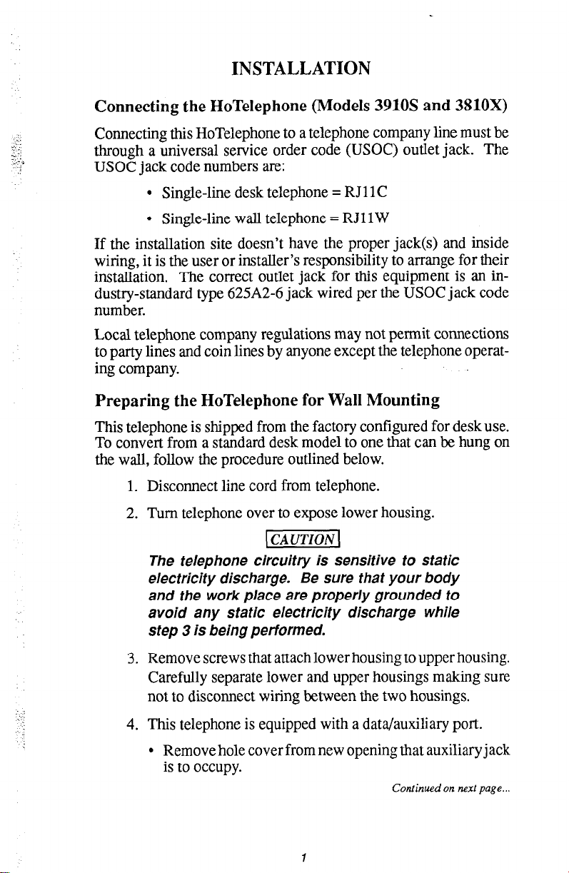
INSTALLATION
Connecting the HoTelephone (Models 3910s and 3810X)
Connecting this HoTelephone to a telephone company line must be
through a universal service order code (USOC) outlet jack. The
USOC jack code numbers are:
l
Single-line desk telephone = RJl 1 C
l
Single-line wall telephone = RJl 1 W
If the installation site doesn’t have the proper jack(s) and inside
wiring, it is the user or installer’s responsibility to arrange for their
installation. The correct outlet jack for this equipment is an industry-standard type 625A2-6 jack wired per the USOC jack code
number.
Local telephone company regulations may not permit connections
to party lines and coin lines by anyone except the telephone operating company.
Preparing the HoTelephone for Wall Mounting
This telephone is shipped from the factory configured for desk use.
To convert from a standard desk model to one that can be hung on
the wall, follow the procedure outlined below.
1. Disconnect line cord from telephone.
2. Turn telephone over to expose lower housing.
(1
The telephone circuitry is sensitive to static
electricity discharge. Be sure that your body
and the work place are properly grounded to
avoid any static electricity discharge while
step 3 is being performed.
3. Remove screws that attach lower housing to upper housing.
Carefully separate lower and upper housings making sure
not to disconnect wiring between the two housings.
4. This telephone is equipped with a data/auxiliary port.
l
Remove hole cover from new opening that auxiliary jack
is to occupy.
Continued on next page...
Page 5
‘.
.l
.,
.i
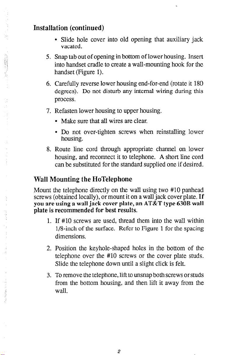
Installation (continued)
l
Slide hole cover into old opening that auxiliary jack
vacated.
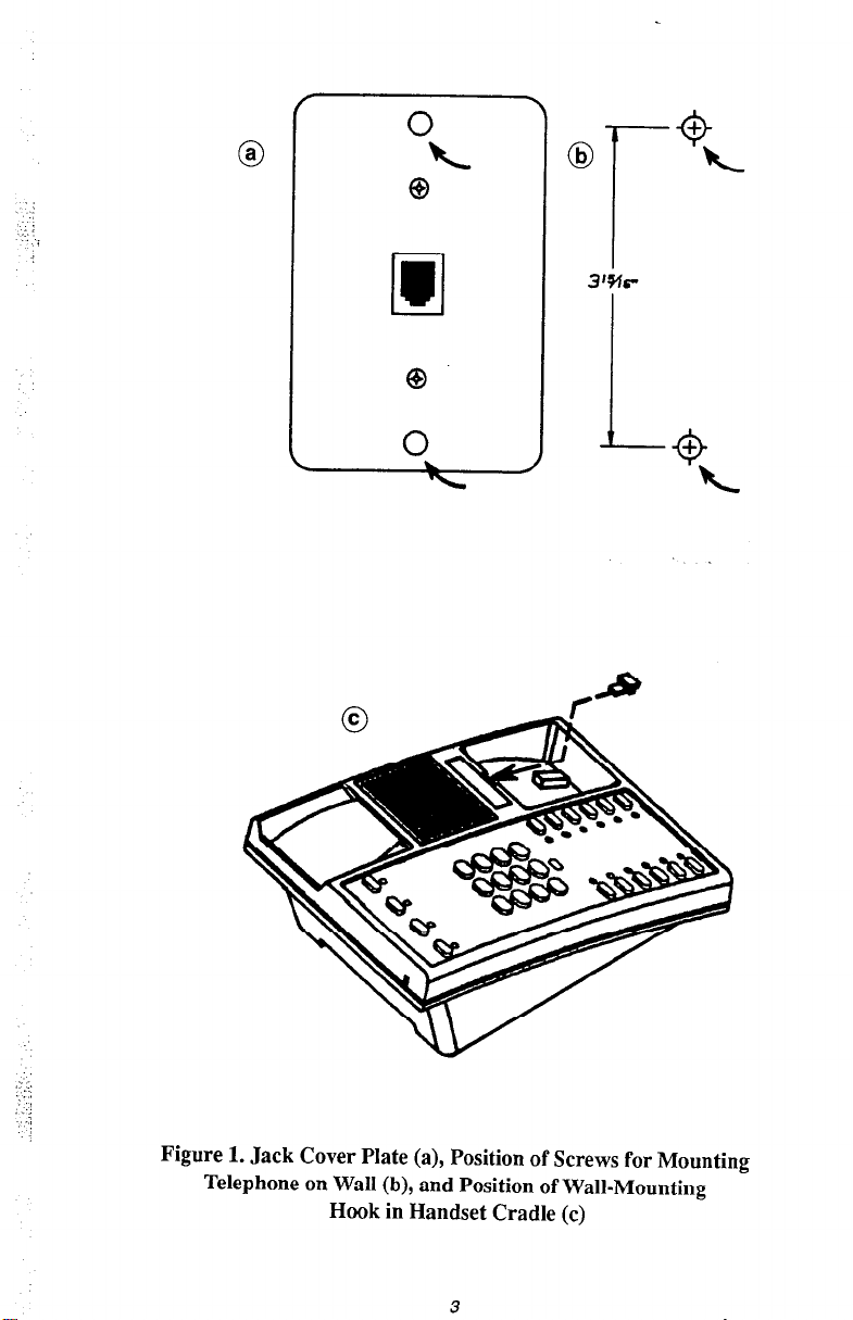
5. Snap tab out of opening in bottom of lower housing. Insert
into handset cradle to create a wall-mounting hook for the
handset (Figure 1).
6. Carefully reverse lower housing end-for-end (rotate it 180
degrees). Do not disturb any internal wiring during this
process.
7. Refasten lower housing to upper housing.
l
Make sure that all wires are clear.
l
Do not over-tighten screws when reinstalling lower
housing.
8. Route line cord through appropriate channel on lower
housing, and reconnect it to telephone. A short line cord
can be substituted for the standard supplied one if desired.
Wall Mounting the HoTelephone
Mount the telephone directly on the wall using two #lO panhead
screws (obtained locally), or mount it on a wall jack cover plate.
you are using a wall jack cover plate, an AT&T type 630B wall
plate is recommended for best results.
If
1. If #lO screws are used, thread them into the wall within
Winch of the surface. Refer to Figure 1 for the spacing
dimensions.
2. Position the keyhole-shaped holes in the bottom of the
telephone over the #lO screws or the cover plate studs.
Slide the telephone down until a slight click is felt.
3. To remove the telephone, lift to unsnap both screws or studs
from the bottom housing, and then lift it away from the
wall.
2
Page 6
._ : .,
,-.:j
-:
Figure 1. Jack Cover Plate (a), Position of Screws for Mounting
Telephone on Wall (b), and Position of Wall-Mounting
Hook in Handset Cradle (c)
3
Page 7
TELEPHONE OPERATION
Operating these single-line telephones (Figures 2 and 3) is
: :
I:.:;
.i,
,:.
straightforward and easy.
Answering a Call
. When telephone rings, lift handset and talk.
Making a Call
Dialing a number,
l
Lift handset and dial number.
Dialing a programmable button function,
l
Lift handset.
l
Press desired programmable button.
Dialing a speed dial number,
l
Lift handset.
l
Press preprogrammed SPEED button.
l
Dial speed dial location number (0 - 9).
NOTE: The SPEED button and speed dial numbers are not available un-
less previously enabled by programming action.
Using Call Waiting
The 3910s and 38 10X model HoTelephones let you switch between
two simultaneous telephone calls. While you are on a call, a tone
will sound in the handset receiver letting you know that another call
is coming in.
To place the first call on hold and answer the second call,
l
Press HOLD button. You will be connected to the Line 2 call.
The Line 1 light will flash and the Line 2 light will turn on
steady.
To return to first call and leave second call on hold,
l
Press HOLD button. You will now be connected to the Line
1 call. The Line 2 light will flash and the Line 1 light will
turn on steady.
To return to first call and drop second call,
l
Press Line 1 button. Line 2 light will turn off and Line 1
light will mm on steady.
5
Page 8

Message Waiting
Indicator
I
I i
Programmable
Button Field
/
I
f
7’k
/ (
’ c
I (
C
3 I 0
J
C
I
Data/Auxiliary
Port (lower side
/
of housing)
--Speed Button
Location
- Pause Control
(Conrral Under Fmplale,
0 0
Line I Button1 -Vol”me Control
0
Speaker On/Off
Button
Port
Figure 2. Model 3910s HoTelephone Controls and Indicators
6
Page 9
Message Waiting
Indicator
I
‘L
1
I
ii.
Programmable
/
Button Field
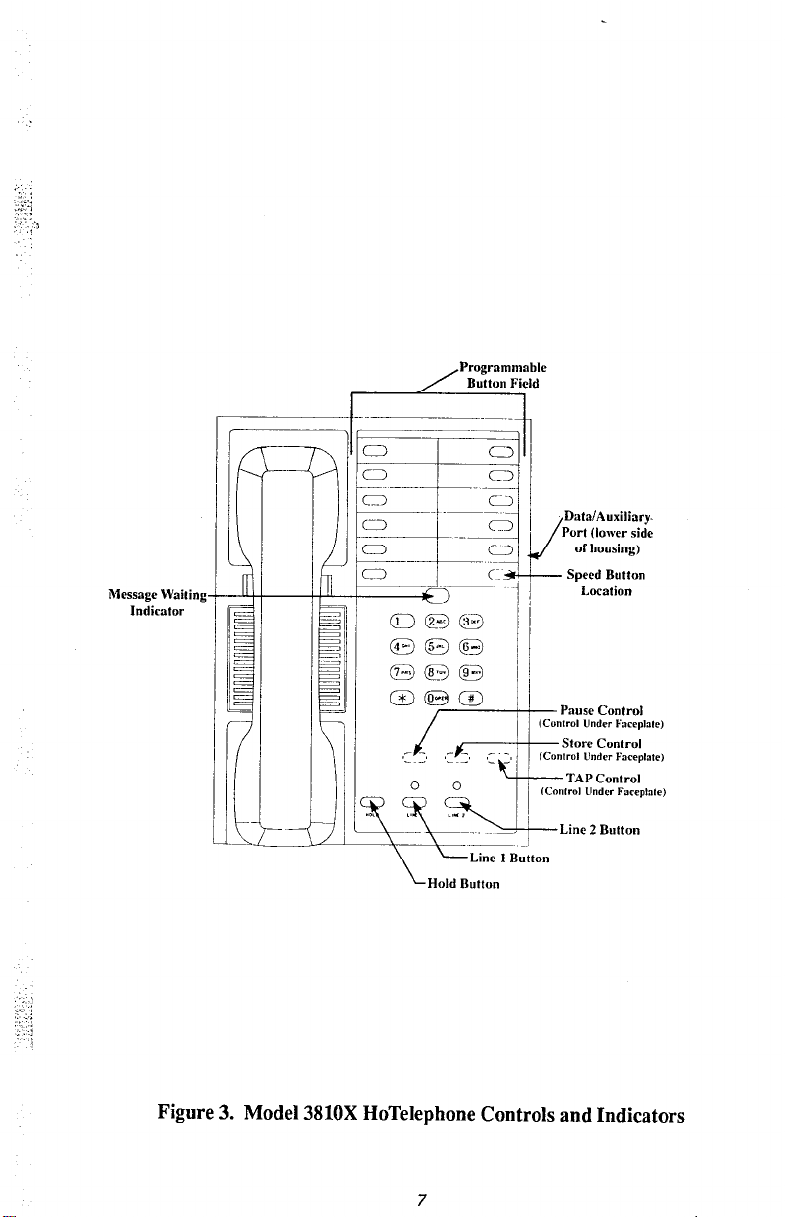
Figure 3. Model 3810X HoTelephone Controls and Indicators
7
Page 10

SPEAKERPHONE OPERATION
(Model 3910s Only)
When you make or answer a call, you can have a conversation
without using the telephone handset, or handsfree, because a
microphone and speaker are built into the telephone set. The
microphone port is located in the front right-hand edge of the
telephone housing. To make sure the speakerphone operates
properly, check to see that this port is not blocked by any obstruc-
tions.
Answering a Call Using the Speakerphone
1. When the telephone rings, press the SPKR button. The
light above the speakerphone on/off button will turn on to
indicate that speakerphone is active.
2. Speak in normal tone of voice toward telephone.
3. If needed, adjust loudness of caller’s voice With volume
control located in front edge of telephone (Figure 2).
4. End speakerphone call by pressing SPKR button again.
Light will turn off and telephone will hang up.
Making a Call Using the Speakerphone
1. Press SPKR button. Note that light turns on to indicate
speakerphone is active.
2. When dial tone is heard over speaker, dial desired number.
3. End speakerphone call by pressing SPKR button again.
Light will turn off and telephone will return to idle state.
Switching Between Speakerphone and Handset During
a Call
Speakerphone to handset,
1. Lift handset from cradle.
2. Continue in-progress call with handset.
3. Hang up handset to end call.
Continued on next page
Page 11

Speakerphone Operation (continued)
Handset to speakerphone,
1. Press
SPKR
button. Light will turn on.
2. Return handset to cradle.
3. Continue conversation.
4. Press SPKR
button to end call. Light will turn off.
10
Page 12

PROGRAMMING
You may store up to 16 keypad digits including the PAUSE or TAP
fixed feature, if needed, at programmable button locations for
autodialing.
All 12 programmable buttons may be used for number storage, or
you may use 11 programmable buttons for number storage and store
a SPEED button function in the lower right-hand programmable
button location (Figures 2 and 3). The SPEED button lets you store
additional numbers using keypad locations. Memory contents are
protected by a long-life lithium battery, which provides memoryretaining power for approximately seven years.
Programming controls are located beneath the telephone faceplate.
Before you remove the faceplate, remove the clear plastic cover
of the message waiting indicator
by pulling it straight up. Then:
1. Remove the two-piece faceplate to gain access to the
programming controls.
2. Refer to Figures 2 and 3 for the
controls for
PAUSE, STORE,
and
actual
TAP.
location‘of the
3. Look in the openings - you will see a small, silver, circular
actuator in each opening. This is the programming control.
4. To actuate each control, carefully press down on it with a
blunt wooden or plastic probe approximately l/g-in,
diameter.
Storing Numbers at Programmable Button Locations
NOTE: The telephone must be connected to the line before you canpro-
gram it.
1. Lift handset.
2.
Press
STORE.
3. Press desired programmable button.
4. Dial number to be stored (16 digits maximum). If needed,
press
TAP
for a hookswitch flash signal and
PAUSE
for a
pause between numbers. A valid entry causes an acknowledge tone or a click to sound from the speaker if you have
a speakerphone and from the handset receiver if you don’t.
An invalid entry causes an error tone or a buzz to sound.
Continued on next page...
Page 13

Programming (continued)
NOTE: A two-secondpause is stored each time the PAUSE control is
pressed. A fued 6.50 msec hookwitch flash signal is stored each
PAUSE and TAP each equal
5.
time the TAP control is pressed.
one digit in the 16-digit total.
Press
STORE
to end programming sequence. After the
16th digit is stored, the programming sequence will end
automatically. Success tone will sound to indicate successful programming sequence.
6. Repeat steps 2-5 for each programmable button.
Enabling the SPEED Button
1. Press
STORE, *,
and lower right-hand programmable
button (Figures 2 and 3).
2.
Press
STORE
again.
3. Label the programmable button “Speed.”
Disabling the SPEED Button
l
Press STORE,
#, SPEED, STORE.
Storing Numbers At Keypad Locations (to be accessed
by SPEED button)
1. Lift handset.
2. Press STORE.
3. Dial speed location from keypad (O-9).
4. Dial number to be stored (16 digits maximum). If needed,
press
TAP
for a hookswitch flash signal and
PAUSE
for a
pause between numbers. A valid entry causes an acknowledge tone or a click to sound from the speaker if you have
a speakerphone and from the handset receiver if you don’t.
An invalid entry causes an error tone or a buzz to sound.
5.
Press
STORE
to end programming sequence. After the
16th digit is stored, the programming sequence will end
automatically. Success tone will sound to indicate successful programming sequence.
6. Repeat steps 2-5 for each speed dial location.
Continued on next page...
12
Page 14

Programming (continued)
Clearing One Programmable Button or Speed Dial
Location
1. Lift handset.
2.
Press
STORE.
3. Press programmable button or speed dial location (O-9) to
be cleared.
4.
Press
STORE
again.
Clearing
All
Programmable Buttons or Speed Dial
Locations
1. Lift handset.
2.
Press
STORE.
3.
Dial% 0000.
4. Hang up handset.
5. Lift handset to continue.
Protecting Programmable Buttons from Being
Reprogrammed or Cleared
1. Lift handset. Press
2.
Dial +I+ 263 5.
3.
Press
STORE
STORE.
again. Success tone will sound to indicate
successful programming.
To remove this protection,
1. Lift handset.
2.
Press
STORE.
3.
Dial # 2635.
4.
Press
STORE
again. Success tone will sound to indicate
successful programming.
NOTE: Programmed buttom or speed dial locations can only be
cleared if they have not been protected or ifprotection has been
removed.
Cont hued on next page..
13
Page 15

Programming (continued)
Using Chain Dial Storage
. If you need to store a number that exceeds 16 digits, you can
store part of it under one programmable button and the rest
of it under another button. Access it by pressing the first
button and then the second. You can store the number under
up to four buttons.
For programming instructions, refer to “Storing Numbers at
Programmable Button Locations” at the beginning of the programming section of this guide.
14
Page 16
MISCELLANEOUS FEATURES
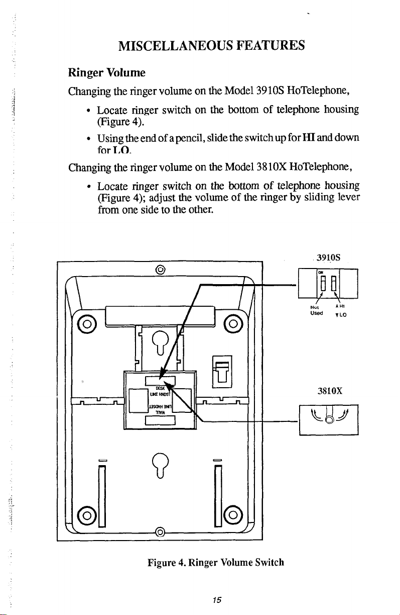
Ringer Volume
Changing the ringer volume on the Model 39 10s HoTelephone,
l
Locate ringer switch on the bottom of telephone housing
(Figure 4).
l
Using the end of a pencil, slide the switch up for HI and down
for LO.
Changing the ringer volume on the Model 3810X HoTelephone,
l
Locate ringer switch on the bottom of telephone housing
(Figure 4); adjust the volume of the ringer by sliding lever
from one side to the other.
Figure 4. Ringer Volume Switch
15
Page 17
Message Waiting Light
The telephone message waiting light may be turned on by a central
answering service to alert the user that a message awaits pickup.
,:-
To receive messages,
l
See lit message waiting light.
l
Lift handset.
l
Dial message service number. When the message is
delivered, the light will be turned off by the answering
service.
NOTE: When the message waiting pair is connected to the tip and ring
pair of the line jack, the FCC registration code of the telephone
will be My and the REN will be Z. The telephone will be so
marked on the registration label attached to the bottom housing.
This KX registered device is intended to be connected behind a
host PBX only. Direct connection to the CO line may not be
compatible and is not permitted without the prior approval of
the telephone company ofice supplying
the
CO line.
Data/Auxiliary Port
This telephone is equipped with a data/auxiliary port that is a
standard RJl 1 configured modular jack and is connected directly
across the tip and ring leads of the telephone line. This port is not
controlled by the telephone hookswitch. It can be used to connect
adjunct devices such as autodialers, modems, and data terminals to
the telephone line.
Some adjunct devices can be operated at the same time that the
telephone is off-hook while others cannot. Refer to the manual
associated with the device for complete details.
16
Page 18
FCC RULES AND REGULATIONS
This telephone complies with Federal Communications Commis-
sion (FCC) Rules, Part 68. The FCC registration label attached to
the bottom housing contains the FCC registration number, the
ringer equivalence number, the model number, and the serial num-
ber or production date. The telephone operating company can
request that they be provided with the telephone number of the
TELCO line involved, the FCC registration number, and the ringer
equivalence number of this telephone.
The ringer equivalence number (REN) is a measure of the load a
telephone device will place on the ringing generator of a central
office telephone company line. In general, aREN of 1 is equivalent
to the load provided by one standard telephone ringer. FCC rules
state that the total REN load on a line shall not exceed 5. When
contacted, the telephone company will provide information on the
maximum number of telephones or ringers that can be connected
to one line, as well as any other applicable technical information.
Any problem with this equipment that causes improper operation
of the telephone network may require the telephone company to
disconnect service to the trouble site. If possible, advance notice
of the disconnect will be given. If advance notice is not practical,
notice will be given as soon as possible. The telephone company
will inform the user of the right to file a complaint with the FCC.
The telephone company can temporarily discontinue service and
make changes that could affect the operation of this equipment;
however, it must provide advance notice of any change to give the
user the opportunity to maintain uninterrupted telephone service.
Connection of this telephone to a telephone company line must be
through a universal service order code (USOC) outlet jack. The
USOC jack code number for a single-line telephone is RJl 1C. If
the installation site does not have the proper jack(s) and inside
wiring, it is the user/installer’s responsibility to arrange for its
installation. The correct outlet jack for this equipment is an industry standard type 625A2-6 jack wired per the USOC jack code
number RJllC.
Local telephone company regulations may not permit connections
to party lines and coin lines by anyone except the telephone operating company. FCC regulations do not permit repair of this telephone
by anyone except the manufacturer or its authorized agent.
17
Page 19

RADIO FREQUENCY INTERFERENCE (RFI)
It is possible for an electronic telephone to generate radio frequency
(RF’) energy while it is in use and interfere with radio and TV
reception. This telephone has been tested and found to comply with
radiation limits for a Class B computing device, pursuant to FCC
Rules and Regulations, Part 15, Subpart J. These regulations are
designed to provide reasonable protection against RFI.
There is no guarantee that interference will not occur in a particular
installation. If a telephone does cause interference to radio or TV
reception (which can be determined by unplugging the telephone),
try to correct the interference as follows:
l
Reorient the receiving antenna of the affected electronic
device.
l
Relocate the affected device or the telephone.
l
Plug the affected device into a different AC outlet.
If necessary, consult an experienced radio/television technician or
the manufacturer of this telephone for additional suggestions. You
may find the following booklet prepared by the Federal Communications Commission helpful: “How to Identify and Resolve
Radio-TV Interference Problems.” This booklet is available from
the Government Printing Office, Washington D.C. 20402. Stock
No. 004-000-00345-4.
Page 20
This manual has been developed by Ccmdial Corporation (the “Company”) and is
intended for the use of its cuskme~ and service pkonnel. The inforkatk in this
manual is subject to change without notice. While every effort has been made to eliminate
errors, the Company disclaims liabiiity for any difficulties arising from the interpretation
of the information contained herein.
The information contained herein does not purport to cover all details or variations in
equipment nor to provide for every possi&e contingency to be met in connection with
installation, operation, or maintenance, Should further information be desired, or should
particular problems arise which are not covered sufftciently for the purchaser’s purposes,
contact Comdial, Customer Service Department, P.O. Box 7266, Charlottesville, Virginia
22906.
COMDlAL
Charlottesville, Virginia 22906-7266
Printed in U.S.A
GCA 70-162.01
4190
 Loading...