

Page 1
Page 2
Table Of Contents
Table Of Contents
Chapter 1 System Overview . . . . . . .
introducing The System
Publication Overview
....................
Understanding The Manyal Scope
Related Publications
Accessories
.................................................
Hardware Summary
Common Equipment Description
Station Description
General Specifications
............................................
..............................................
......................................
.............................................
............................................
Chapter 2 Description Of System Features
Chapter 3 Installation
Mounting Considerations
Mounting Procedure
AC Power Connection
..............................................
..........................................
............................................
...........................................
............
Line Connections
Line Grounding
Station Connections
Station Wall Mounting
..............................................
...............................................
...........................................
..........................................
. . . . . . . . . . . . . . . . . . . . . . . . . . . . . . . . . . l-l
..................................................................
.....................................
..................................
................................
......................................
Power Failure Station Connections
Auxiliary Equipment Interface
Common Audible And Auxiliary Ringing Interface
External Paging Interface
External Paging Interface
Data Device Connections
Music Interface
..............................................
Add-On Expansion Modules
Introduction
................................................
........................................
Line Port
........................................
.........................................
Add-On Expansion Module Installation
Software Cartridge
Introduction
Installation
..............................................
................................................
................................................
Data Communications With The Digital Telephone System
Equipment Required
Connections
..
Communication Procedures
...........................................
.............................................
.......................................
Caller Identification Service Support
System Checkout And Failure Isolation
Initial Condition
..............................................
...................................
......................................
............................
...................................
..................................
.........................
.....................................
...................................
Checkout ................................................
Failure Isolation
Installer/User Information Regarding FCC Rules And Regulations
.............................................
.....................
1-2
1-3
l-4
l-6
l-l
2-1
3-1
3-2
3-4
3-4
3-6
3-6
3-10
3-16
3-20
3-22
3-23
3-24
3-26
3-27
3-26
3-30
3-31
3-31
3-34
3-36
3-36
3-36
3-38
3-38
3-42
Continued on next page . . .
Page 3
Table Of Contents
.......................................
General Programming Information
Programming Overlays.
Supporting DigiTech Telephones
Converting Button Designations When Using Impact Telephones
Class Of Service Programming
Master Clear And Class Of Service Defaults
System Configuration
System Configuration
System Configuration
Station Configuration
Station Configuration
Station Configuration
Miscellaneous Programming Features
Video Display Terminal Programming Feature
Video Display Terminal Programming Procedure
Video Display Terminal Remote Programming Configuration
Class Of Service Configuration Records
System Configuration Records
System Configuration
System Configuration
System Configuration
Line Configuration Records
Station Configuration Records
Station Button Mapping Record
Miscellaneous Programming Features Records
Programming Overlays
Chapter 5 System Operating Characteristics
Operator’s Manuals
Typical DigiTech Telephone Features
Typical Impact Telephone Features
Typical Americom Telephone Features
Feature Dialing Code Numbering Plan
Controls And Indicators
System Ringing Patterns
Intercom Call Progress Tones
Line Select Lights
Message Waiting Light
Intercom Light
Speaker Light.
Chapter6 Maintenance
Technical Assistance And Repair Service
Fuse Location
Frequently Asked Questions Concerning The Digital Telephone System
Miscellaneous Features
Timing Features
.
Feature Inhibiting
..............................................
............................................
Miscellaneous Features
Button Mapping
Miscellaneous Features
Timing
Feature Inhibiting
...........................................
............................................
............................................
..........................................
..............................................
.............................
..............................................
................................................
.............................................
...............................................
.......................................
..........................................
.....................................
.....................
........................................
.................................
...............................
.................................
................................
.............................
..................................
...................................
...............................
............................
......................
..................................
.......................................
............................
.....................................
................................
.........................................
........................................
.......................................
...............................
.................................
...................................
....................................
..................................
...................................
..........................................
..........................................
.......................................
.................
.................................
...
.................
4-2
4-2
4-3
4-4
4-5
4-12
4-15
4-22
4-22
4-36
4-43
4-78
4-79
4-79
4-87
4-88
4-88
4-90
4-91
4-92
4-93
4-94
4-l 00
4-l 17
5-l
5-2
5-3
5-4
5-5
5-6
5-7
5-8
5-10
5-l 1
5-l
5-12
6-l
6.2
Publicationindex.. ..............................................
Continued on next page
. .
Page 4
Illustrations
Figure
Figure l -2a. Station Images
Figure 1-2b. Station Images
Figure
Figure
Figure 3-l. Mounting Dimensions
Figure 3-2. AC Power Connection And System Grounding
Figure 3-3a. Common Equipment Line Connections
Figure 3-3b. Typical Line Connections.
Figure 3-4a. Common Equipment Station Connections
Figure 3-5. Station Wall Mounting Details
Figure 3-6. Typical DSS/BLF Console Connections
Figure 3-7. Power Failure Connection
Figure 3-8. Auxiliary Interface Connections
Figure 3-9. Typical Common Audible Interface Wiring
Figure 3-10. Typical External Paging Connection
Figure 3-11. Typical External Paging Connection
Figure 3-12. Typical Data Device Connections
Figure 3-13. Music Interface
Figure 3-14. Add-On Expansion Module Configuration
Figure 3-l 5. Expansion Module Installation
Figure 3-16. Software Cartridge Installation and Removal
Figure 3-17. Data Communications Interconnection Diagram
Figure 3-18. Caller ID Interface, Common Equipment, and Data Printer Interconnection
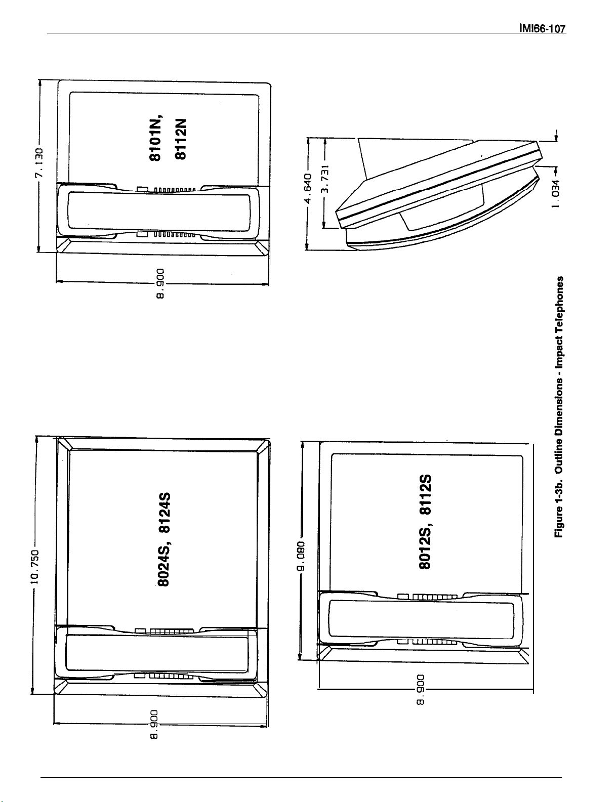
Outline Dimensions
Outline Dimensions
Outline Dimensions
Common Equipment
DigiTech Telephones
Impact Telephones
DigiTech Telephones
Impact Telephones
.......................................
....................................
..................................
..................................
...................................
.................................
...............................
.........................................
.................................
............................
..............................
...............................
...........................
............................
..........................
.............................
...........................
............................
...........................
..............................
Line Port
........................
...........................
.........................
........................
..........
3-3
3-5
3-8
3-9
3-12
3-13
3-19
3-21
3-22
2-23
2-25
3-26
3-27
3-29
3-30
3-32
3-35
3-37
3-39
3-40
Table 3-l. Line Connections
Table 3-2. J-l Station Connections (4-Line,
Table 3-3.
Table 3-4a.
Table
Table 3-5. Line Connections
Table 3-6. Station Connections
Station
Station Connections(l6-Line, 3SStation Base Unit)
Station
.........................................
408 Expansion Module
408 Expansion Module
Tables
Base Unit)
l&Station Base Unit ......................
Base Unit) ....................
...........................
..........................
......................
....................
3-14
3-l 5
3-l 6
3-17
3-31
3-33
V
Page 5

Chapter 1
System Overview
Introducing The System
System Overview
The digital telephone system is an expandable
communications system with many attractive
characteristics including the following:
Unitized base unit which includes all system
features.
self-contained.
Expansion modules which increase station and
line capacity.
available. It can be added singly or in pairs to
increase the station and line capacity of an existing
base unit installation.
Subdued off-hook voice announce (SOHVA)
feature.
talk to a busy station without being heard by the
outside party at the busy station. The called user can
easily send back a pre-programmed LCD message or
talk to the caller without being heard by the outside
Programmable buttons.
buttons can be programmed to provide functions such
as direct station selection (DSS), auto dial, system
feature access, line access, messaging and more.
The base unit is full featured and
A 4-line, 6-station expansion module is
The SOHVA feature allows a station user
Many of the telephone
Programmed buttons helps station users eliminate
manual dialing errors.
Service observing.
quality of service without interrupting calls by
monitoring a trainee’s activity without being heard by
the distant party at the trainee’s station.
Dual intercom.
provided so that station users can handle two intercom
calls at once. One intercom call can be placed on hold
while a second intercom call is serviced or both calls
can be conferenced together.
Station Message detail accounting (SMDA)
reports.
costing of all calls made over outside lines. It also
provides SMDA printout reports of all costed calls as
well as displaying call costs on LCD speakerphones.
Caller ID interface.
provides an interface for a caller ID decoder device.
The device can decode the ID data that the CO
delivers to it over the outside lines, and send the
decoded information out the RS-232 data port for
printing.
Supervisors can help insure
A second intercom button can be
The system provides built-in estimated
The digital telephone system
l-l
Page 6
System Overview IMl66-107
Publication Overview
Understanding The Manual Scope
This publication contains a technical discussion of the
digital telephone system. Included in this manual is
the following information:
Chapter 1, System Overview:
provides a generalized understanding of the
This chapter
l
l
letter of I or later
l
l
Support for digital single-line proprietary telephone
l
system, an explanation of the supporting
documentation, and a summary of the equipment
hardware.
Chapter 2, Feature Description:
This chapter
l
speakerphones
provides a detailed discussion of the features
provided by the digital telephone system.
l
Chapter 3, Installation:
This chapter provides
detailed installation instructions and connection
details.
Chapter 4, Programming:
This chapter provides
detailed programming instructions for setting the
operating parameters of the system.
Chapter 5, Operating Characteristics:
This
chapter summarizes operating characteristics and
provides special tone and indicator details.
Chapter 6, Maintenance:
Special maintenance
details are provided in this chapter.
This manual includes information about enhancements
to the digital telephone system that are provided by
periodic software releases. The information was
previously published in the following Technical
Support for /mpact digital proprietary telephones
TAB099
l
l
Expanded options for account code entry
l
Support for caller ID service
TAB113
Support for the lmpacf proprietary multiline
telephone (product code 8112N)
Support for the Americom telephones (product
code 70nnn and 71 nnn) with the 10408,10816, and
Telephone type query for button mapping through
VDT programming
Additional support for caller ID service
Advisory Bulletins.
TAB068
l
Support for the ATI-D analog terminal interface
device
l
Support for the DigiTech DD32X and Americom
Software revision 8 and later
The following related publications contain additional
information applicable to this system.
General Information
DSS/BLF consoles
l
Provision for programming a night mode button
Components
Simplified hybrid operation
Support for DigiTech telephones with a revision
Enhanced automatic call back
Support for ExecuMail voice processing system
Software revision 11 B
Enhanced operation with Americom LCD
Software revision 12A
Software Revision 13A
Enhanced SMDA reporting
Software Revision 138
632 software cartridges.
Related Publications
TAB080
l
Support for dual DD32X DSSIBLF consoles
TAB091 A
Software revision 9 and later
Software revisions 10 and 11A.
Additional dial time for the DISD option
Changed defaulted first choice signalling style for
intercom calls
Supports both on-hook and off-hook call
announcing from speakerphones
Enhanced subdued off-hook voice announce
operation
Expanded personal ring tone choice
User Information
Operation With DigiTech Telephones and Consoles
(product codes
7714X, and
all with
revision I and later, and DD32X)
System User’s Guide
DigiTech Multiline Telephone
System User’s Guide
DigiTech Station User’s Guide
DigiTech Single-Line Proprietary
Telephone User’s Guide
l-2
Page 7
System Overview
User’s Guide
Operation With /mpactTelephones and Consoles
(product codes 80248,8124S, 8012S, 8112S, 8112N,
Operation With Americom Telephones (product codes
701 OS, 7016S, and 711 OX)
and
System User’s Guide
System User’s Guide
Attendant’s Supplement
Telephone User’s
Impact DSWBLF Console
User’s Guide
Guide
Guide
Accessory Information
Accessories
By employing the Analog Terminal Interface (ATI-D)
device, the digital telephone system can support the
operation of the following accessories:
l
attendant equipment
l
Industry-standard telephones and telephone
devices
The Comdial DigiTech and
LCD
speakerphones with product codes of 7700s and
80248, revision H and earlier, include a built-in
headset port. Speakerphones with a revision of I and
The Supra Polaris headset by PLANTRONICS INC,
345 Encinal Street, Santa Cruz CA, 95060 is
compatible with the digital telephone system and may
be connected to the headset port or auxiliary jack of
these LCD speakerphones.
Two Supra Polaris models are available for use:
l
l
NOTE: The system delivers subdued off-hook voice
Using the Caller Identification Interface (product code
information as part of the SMDR printout and as ASCII
data input for use with personal computer based
application programs.
Americom Station User’s Guide
Analog Terminal Interface (ATI-D)
Industry-Standard Telephone
OH2001 Monaural Single Receiver
OH2002 Binaural Dual Receiver
announce (SOHVA) messages to the headset
port. Because a telephone headset exhibits a
“coupling” effect between the ear piece and the
microphone,
may allow the outside
to
hear the SOHVA message. The Plantronics
headset
minimize the coupling effect but
may not complerely eliminate it.
Hardware Summary
The digital telephone system consists of an electronic
Digital Service Unit (DSU), usually referred to as
common equipment, optional expansion modules to
extend station and line capacities as required, a
software cartridge containing the operating system
programming, dedicated digital electronic key
telephones, and interconnecting wiring consisting of
small, 2-- or 4-conductor, twisted-pair cable.
The station and line capacity of the base unit and
optional expansion module are per the following chart.
MODEL CO/PBX STATION
NO. CAPACITY CAPACITY
GO408
GO81 6 8 16
G1632
GM408 4
The digital telephone system is full featured, and
supports all Comdial proprietary digital telephone
models.
The digital system is expandable in both line and
station capacity with the addition of add-on expansion
modules.
1-3
4 8
16
32
8
Page 8

System Overview
Common Equipment Description
The common equipment base unit is a fully electronic
device. It is essentially a special purpose computer
system acting as a communications controller between
central office (CO), private branch exchange (PBX), or
supplied lines and the proprietary digital
telephone stations. The software architecture of the
common equipment provides complete system support
and great flexibility of operation.
The system is fully digital and is ISDN up-gradable
with two usable time slots available for each station.
The digital information passes over time division
multiplexing (TDM) highways. The digital information
is an encoded version of the voice transmission and
control signals that are translated into computer
language. The TDM highway can transmit several
signals over a single pair of wires at the same time.
The signals are governed by a system clock. This
clock creates an overall point of reference against
which the TDM information is synchronized and
partitioned into time slots. A time slot is a portion of
time assigned to a particular position of the system
clock. Each time a particular clock position is reached,
the information associated with that position can be
read. As the system clock goes through the clock
cycle, all necessary digital information is passed
between the pieces of equipment sharing the highway.
The common equipment consists of a base unit, which
provides complete feature support, and optional
expansion modules which provide extended station
and line coverage.
The common equipment is contained in a functional,
modem-style metal housing of contemporary design in
keeping with the needs of the modem off ice
environment. It is engineered to be wall or rack
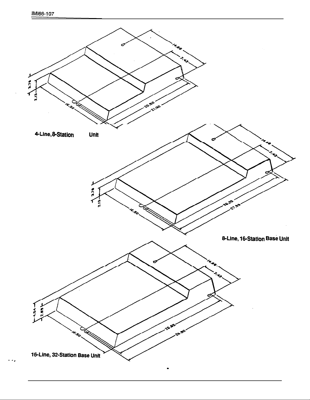
mounted. The outline dimensions of the common
equipment base units are illustrated in
Figure l-l.
l-4
Page 9
System Overview
Base
Figure l-l. Outline Dimensions
l-5
Common
Equipment
Page 10
System Overview
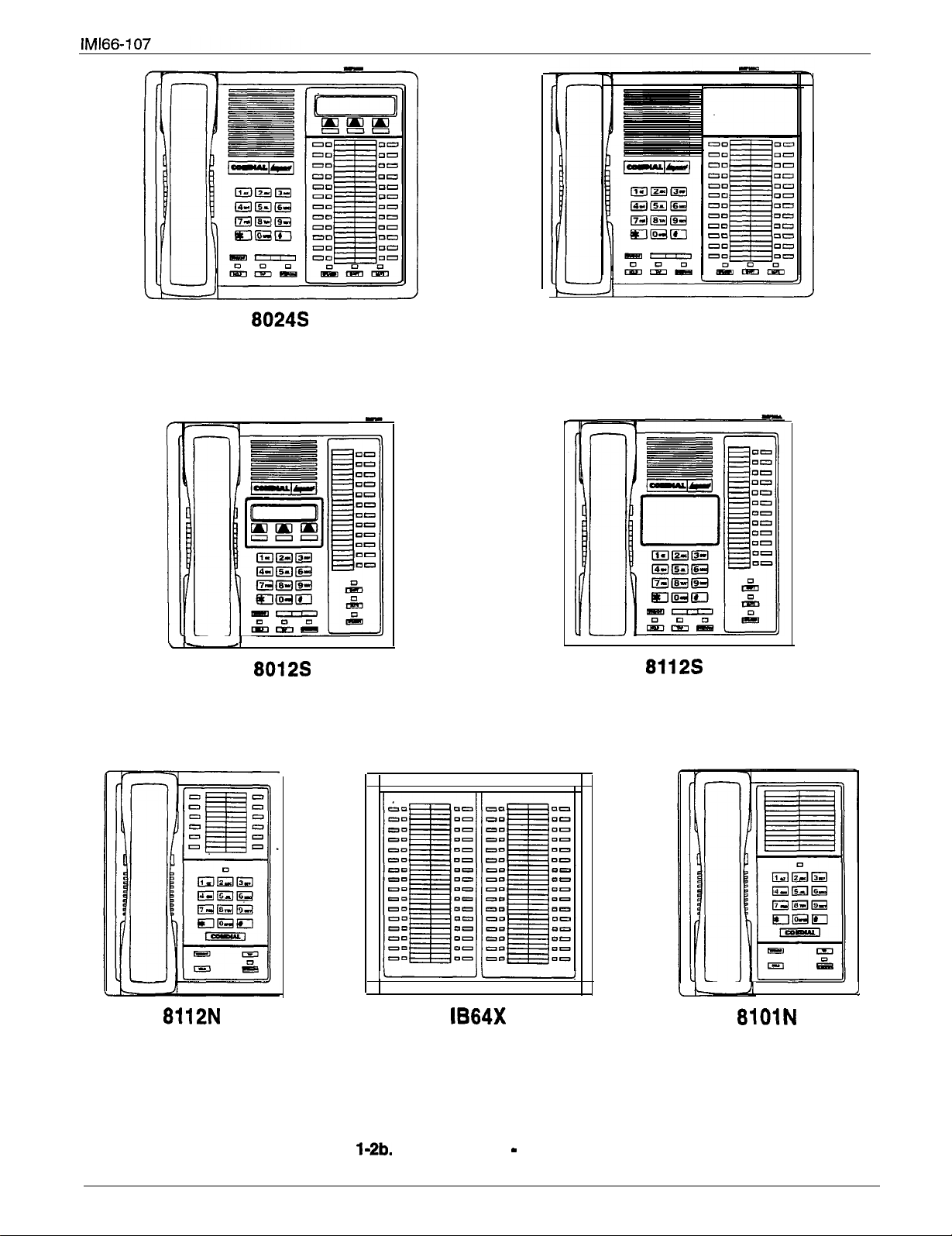
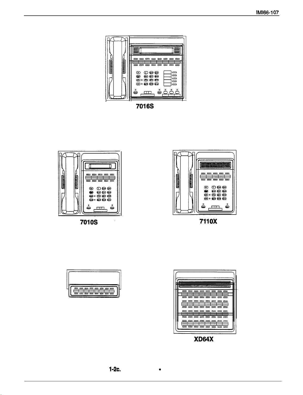
Station Description
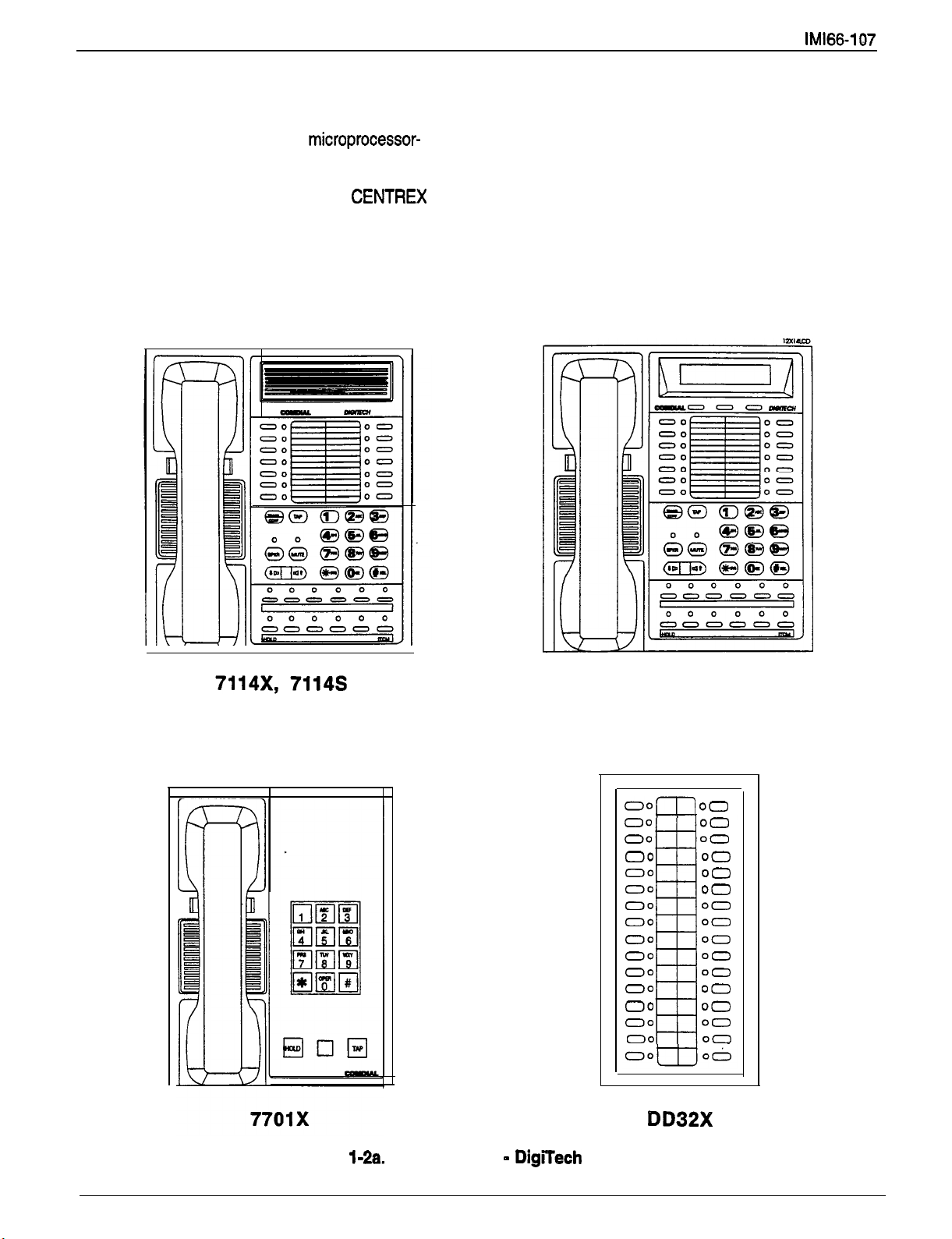
The digital telephones employed with the digital
telephone system are electronic, microprocessor-
controlled, devices. They allow not only multiline
pickup but also single button access to features
available from the serving CO, PBX, or CENTREX
switch as well as the common equipment. The digital
telephones are available in several different images
with several models available in each image. The
images and dimensions of the various digital
telephones are shown in
Figures 1-2 and 1-3.
7700s
Figure
Station Images
1-6
DigiTech Telephones
Page 11
81248
System Overview
J
Figure
Station Images
1-7
Impact Telephones
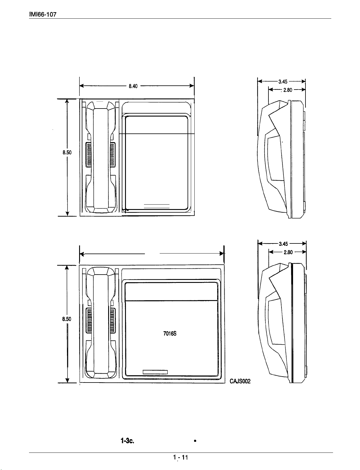
Page 12
System Overview IMl66-1 a7
XDA16
Figure 1-2~. Station Images
Americom Telephones
1-8
Page 13
System Overview
8.625"
4
X658"-
4.983"
4.069"
7114x
7114s
7700s
.
4,007"
2.887"
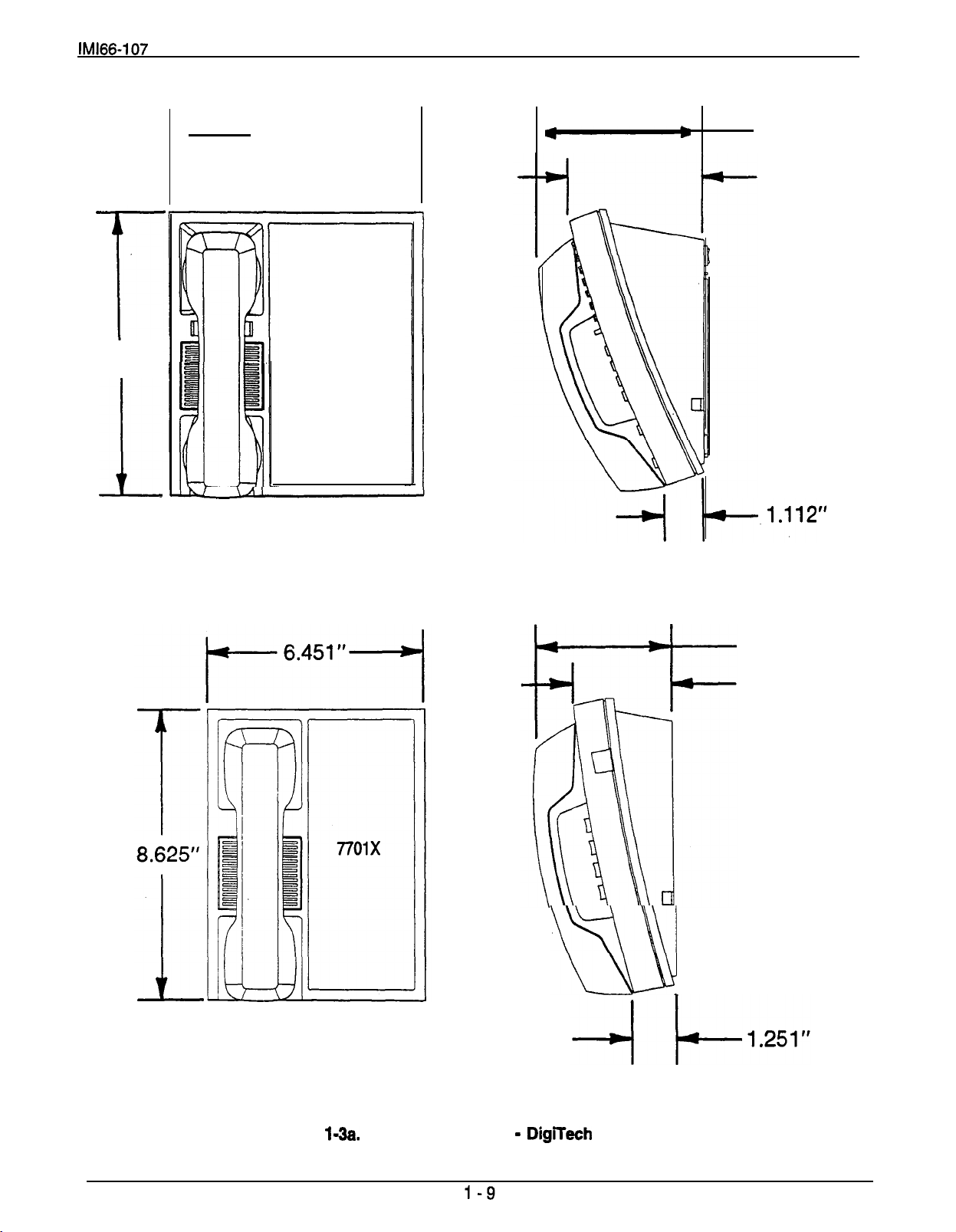
Figure
Outline Dimensions
DigiTech Telephones
Page 14
System Overview
l-10
Page 15
7010s
7110x
System Overview
I
10.55
I
Figure 1-3~. Outline Dimensions
Americom Telephones
Page 16
System Overview
General Specifications
SYSTEM CAPAClTY Go408 GO816
LINES
STATIONS
4
8 16
8 16 4
Two per sta. Two per sta. Two per sta. Two per sta.
INTERCOM PATHS
Non-blocking Non-blocking
MAXIMUM SIMULTANEOUS
INTERCOM CONVERSATIONS
PAGING PORTS
PARK ORBITS
Non-blocking
1 1
9
Non-blocking Non-blocking Non-blocking
9
SPEED DIALS
SYSTEM
STATION
AUTODIALS
POWER FAIL CIRCUITS
POWER REQUIREMENTS (Fully loaded system)
VOLTAGE
CURRENT
POWER:
99
10
Unused buttons
1
Go408
7ow
99 99
10 10 not app.
Unused buttons Unused buttons not app.
1 1
GO816
go
129
VAC Singlephase
2.0 A
135w
VOLT/AMPS
COMMON
DIMENSIONS (approx.)
WIDTH (inches)
HEIGHT(inches)
DEPTH (inches)
WEIGHT (pounds)
STATION DIMENSIONS (approx.)
Go408
16.5
21.3
3.8
17.5
Wide Image
GO816
16.5
27.1
3.8
26
Narrow Image
G1632 GM408
32 8
Non-blocking
1
9
Non-blocking
not app.
not app.
not app.
1
G1632 GM408
all models
not app.
not. app.
200VA
G1632
16.5
not app.
GM408
16.5
27.6 9.25
4.5 1.75
30.5 xxx
Single Line Proprietary
FOOTPRINT (inches)
WEIGHT (pounds)
Impact
FOOTPRINT (inches)
WEIGHT (pounds):
Americom
FOOTPRINT (inches)
WEIGHT (pounds)
(Maximum Combinations At Any One Trme)
SMDA STORAGE CAPACITY PER CARTRIDGE
STATION CABLE REQUIREMENTS
TYPE
MAXIMUM LENGTH
SWITCHING PRINCIPLE
8.625 X 7.658
2.5
not app.
not app.
10.75x8.9 9.08x8.9
2.25
10.65X8.5
2.9
2.25
8.4X8.5
2.1
GO408 and GO81 6
1 five-way plus 1 three-way
plus 2 SOHVA
2 four-way plus 2 SOHVA
1 four-way plus 3 three-way
5 three-way plus 1 SOHVA
800
1600
6.5x8.5
1.9
8.9x7.1 3
1.75
not app.
not app.
G1632
4 five-way plus
1 three-way
plus 1 SOHVA
6 four-way plus 2 three-way
3 four-way plus
16 three-way
9 three-way
1600
1800
1009 feet with 24 gauge wire, 2000 feet with 22 gauge wire
Digital, time division multiplexing (TDM). Provides non-blocking
switching with stored program control
Page 17
TERMINATIONS
STATION
Standard 50-pin male connectors for connection to external
distribution field.
LINE
Standard, 8-conductor mini-jack (USOC 14C)
STATION MESSAGE DETAIL RECORDING PORT
FORMAT
PARITY
DATA BlTS
STOP BITS
BAUD RATE
HANDSHAKING
Serial, pseudo RS-232C
None
7 or 8 (programmable)
1 or 2 (programmable)
Programmable in class of service
Xon
Hardware
CABLE LENGTH
500 Feet maximum
MUSIC IiJTERFACE
3
INPUT LEVEL
INPUT IMPEDANCE
CONNECTOR
Volts
Approximately 500 Ohms
RCA phono jack
PA PORT
OUTPUT LEVEL
OUTPUT IMPEDANCE
CONNECTOR
Approximately 500 Ohms
RCA phono jack
System Overview
CTS
peak-to-peak maximum
CENTRAL OFFlCE LlMlTS
LOOP LIMITS
CABLE INSULATION LEAKAGE
INDUSTRY/REGULATORY STANDARDS
MEMORY RETENTION
POWER LOSS
FCC REGISTRATION NUMBER
KEY SYSTEM
HYBRID SYSTEM
RINGER EQUIVALANCE NUMBER
PRODUCT CODES
4-Line , &Station
GO81 6
G1632
GM498
8-Line, 16Station
1 &Line, 32Station
4-Line, 8Station
Expansion Module
1900 Ohms maximum loop
15,000 Ohms minimum
FCC Certified, part 15 (Class A)
FCC registered (fully protected)
EIA RS478
Bell publication 48002 guidance
Hearing aid compatible handset
68 hours minimum
1.38
7714X DigfTech
Multiline Monitor Telephone
Speakerphone
10816, SO81 6
LCD Speakerphone 11632, s1632
7701 X DigiTech Single-Line Proprietary Telephone
80248 /mpact 24-Line LCD Speakerphone
81248 Impact
Speakerphone
LCD Speakerphone
SO408
8101 N Impact Single-Line Proprietary Telephone
8112N Impact Muttiline Proprietary Telephone
701 OS Americom 1 O-Line LCD Speakerphone
Americom 64-Button DSS/BLF Console
Page 18

Description Of System Features
Cha
ter 2
Description Of
Abandoned Hold Release
Refer to the discussion titled
Ho/d.
Access Denied
Refer to the discussion titled Line Features.
Account Codes
(With Forced Positive Verification)
System users can employ account codes to identify
calls by category or by any other desired grouping so
that the system can print reports. The account code
entry can be voluntary or, beginning with software
release 13A, the programmer can arrange the system
so that the users are forced to enter an account code
before they can make an outgoing call. The system
compares the account code entered by a station user
with a list of programmed account entries.
The programmer must program the system so that it
verifies an entered account code as valid. If he or she
enables verification and the system cannot match an
account code that a user has dialed with the
programmed account code entries, the system will
sound an error tone if account code entry is voluntary,
or it will prevent the user from further dialing until he or
she enters a matching account code if account code
entry is forced.
A user must enter an account code either.before
dialing an outgoing call or after the distant party on an
incoming call has hung up. Additionally, users may
enter an account code before they select a line for an
outgoing call if they wish. When they enter an account
code without a line selection, the code will apply to any
line they subsequently select at that station. On
incoming and outgoing calls, the user who enters the
account code is associated with the call record except
when the call is transferred. On transferred calls, the
transferee is associated with the call record.
date and time message. If the account codes are
forced and the call is outgoing, then the line is dropped
at the end of the display time if the user has not
entered a valid account code. The programmable
range for the display time is 1 to 20 seconds. When
the feature is not enabled, the system inhibits the
display prompt.
When a station user activates the last number redial or
automatic radial features for outgoing calls, the system
will automatically re-use the last account code the user
entered at that station unless he or she enters a new
one before activating the redial feature.
In addition to turning on the account code feature,
enabling its verification, and making it either voluntary
or forced, the programmer must set the account code
length, specify the number of digits that the system will
verify, and make up the entire list of account codes
that the users will use. Account code length defines
the number of digits that a user must enter before the
system will accept the code. The length can range
from three to 16 digits but cannot be lower than the
verified account code length. The verified account
code length defines the number of digits that the
system will verify before it accepts an account code as
valid. As well, verified account code length defines the
number of valid account codes that a programmer can
store (as shown in the following table). A programmer
should be aware that when he or she changes the
verified account code length, the system automatically
empties the list of valid account codes.
Digits Verified Number of Valid Account Codes
3
4
9,
10
1000
400
266
200
160
As a feature to LCD speakerphone users, the
programmer can arrange for a message to appear in
the telephone’s display to prompt the user to enter an
account code during incoming or before outgoing calls.
He or she can also assign the length of time that the
display appears. The user must enter account code
digits after the message appears. If the programmer
has set the system to verify code entry, it then makes
a verification attempt. If the system cannot verify the
account code it causes the display to show an error
message. The user may then re-enter the account
code at this point. If the verification attempt is
successful (or if the system does not require that the
code be verified), the display will return to its normal
Even though a programmer has arranged a system to
force users to enter account codes before making
calls, they can always dial certain programmer-defined
emergency numbers without an accompanying
account code entry. The system allows a maximum of
three programmable emergency numbers. The
minimum length of an emergency number is 1 digit
and the maximum length is 12 digits. Users may dial
emergency numbers manually, through system speed
dial, personal speed dial, last-number redial, or
automatic redial -- with or without account code entry.
2-1
Page 19
Description Of System Features
Account Codes
Account Code Button
A programmer can use station class of service
programming to assign an account code button to any
programmable button location at a station as part of
the button mapping procedure. With this account code
button available, the user can press it and then dial an
account code without interrupting the call. Only the
user of the Account Code button will hear the DTMF
tones when he or she dials the code. The distant
on-line party will not hear the DTMF tones, and the
system will not place the line on hold. The user can
hear the distant on-line party while he or she is dialing
an account code. If the telephone does not provide an
account code button, the user must dial an intercom
code before he or she dials the account code digits.
All-Call Paging
Refer to the discussion titled Paging.
Analog Terminal Interface Support
With software release revision 8, the digital telephone
system supports the operation of the Analog Terminal
Interface (ATI-D). The ATI-D is a multipurpose
on-premise accessory with dual circuits that provide
an industry-standard telephone interface. This feature
adapts most industry-standard (IST) devices and the
telephone system. The ATI-D accepts both tone and
pulse (rotary) dialing from these devices. Each ATI-D
circuit will drive a load with a maximum ringer
equivalence number (REN) of 2.0 thus allowing more
than one IST connection at each ATI-D circuit input.
The ATI-D supports a wide variety of IST equipment
such as model 500 and 2500 telephones, cordless
telephones, answering machines, and FAX machines.
The ATI-D is housed in a metal enclosure
powered by the telephone system through the station
port connections. It contains a ringing generator to
generate a ringing signal for the IST devices.
Area Paging Interface
Refer to the paragraph titled External Paging interface
found in the discussion titled Paging.
continued
is
Automatic Dialing Of Stored Numbers
Automatic Dialing
The system supports up to 22 automatic dial (autodial)
numbers per station. Autodial buttons can store up to
16 digits plus an intercom or line selection. Stored
digits include 9-0,
pause at any point where the HOLD button is pressed,
and stores a hookflash at any point where the TAP
button is pressed. Automatic dialing provides a way to
obtain one-button access to frequently used system
features. This feature does not require any class of
service to enable it.
Programmable DSWBLF
A station user can store one-button, direct station
selection (DSS) at any memory button location to
create a DSS memory button. When this button is
pressed, any active outside call, is automatically placed
on hold and an intercom call is automatically made to
that previously stored station number. The visual
indicators of the stations programmed at the button
locations form a busy lamp field (BLF). The BLF
conveys station status to the user. An autodial
number can also be programmed as a secondary
function at every DSS/BLF memory location. No class
of service is required.
Station Speed Dial
Each station provides 10 speed dial number locations
at the keypad buttons. Station speed dial numbers
can be up to 16 digits in length and can include line or
intercom selection, numbers, #,
hookflash signals. A user can store a pause by
pressing the HOLD button and store a hookflash
signal by pressing the TAP button.
System Speed Dial
The system provides 99 system-wide speed dial
numbers. The system speed dial numbers can be up
to thirty-two digits in length, and can include numbers,
#,
programs the system speed dial numbers at station 10
or 12 for use at every station in the system. No class
of service programming’ is required.
Automatic Hold For Intercom
Assist Button
Refer to the discussion titled Messaging.
Refer to the discussion titled Hold.
Automatic Hold
Automatic Callback
Refer to the discussion titled Intercom.
Refer to the discussion titled Hold.
Automatic Pause Insertion
Refer to the discussions titled Automatic Dialing and
and #. The system stores a
pauses, and
pauses, and hookflash signals. The attendant
Transfer To Line
2-2
Page 20

Account Codes
Quantity Of Emergency Numbers For Forced
Account Codes
With software release 14A, the quantity of emergency
numbers that the forced account code feature
provides increases from three to 10. There is no
change in programming required to achieve this from
the method currently discussed in the programming
chapter of your system manual.
continued
(TAB1 17~35)
Page 21

Description
System Features
Automatic Redial (Of Busy
Number Or Unanswered Call)
Refer to the discussion titled Redialing.
Automatic Station Relocation
With this feature, the system will automatically
recognize a particular station should that station be
relocated to a new station port. When someone
places a telephone at a new port location, it will
continue to provide the same class of service
parameters and respond to the same extension
numbers as it did at the original station port. A
programmer must enable this system feature using
system class of service programming. As an added
feature when someone plugs an LCD speakerphone in
a new station port, the system will prompt the user on
the display to verify the relocation of features.
Auxiliary Equipment Interface
An installer can use the auxiliary equipment interface
to connect a telephone device or a data device to an
outside line ahead of the common equipment. The
system can detect an off-hook condition in a device
that an installer has connected to the auxiliary
equipment interface, and turn on the status light for
that line at telephones that have that line appearance.
It does this to indicate that the line is busy and not
available for station use. Auxiliary equipment interface
connections provide connections to lines 2 and 4. A
user cannot interrupt an external device by pressing
the line button unless the line has been programmed
to be non-private.
Auxiliary Ringer Interface
Refer to the discussion titled Ringing.
Background Music
Refer to the discussion titled Music features.
The system provides all of the basic, lA2-type, key
service features. These features are: selective line
pickup, common line pickup, multiline pickup, and
hold. No special class of service programming is
required.
Battery Back-Up (Chassis, Cable, And Batteries)
The manufacturer offers battery back-up assemblies
including chassis, cable, fuses, and batteries as
optional kits available through normal distribution
channels. The assemblies are designed so that
installers can connect them directly to the
uninterruptable power source (UPS) interface located
not require any action from the telephone user to
make it operate on battery power nor does it require
any class of service programming action on the
programmer’s part.
Battery Back-Up Interface
The common equipment cabinet provides an interface
for an optional battery back-up kit to give full
uninterrupted system power in case of an AC power
loss. The switching and charge circuitry are in the
common equipment, while the batteries, chassis, and
cable are packaged as a separate option. When
plugged into an active AC power source the common
equipment will constantly charge the attached
batteries. Built-in circuitry automatically switches to
battery power when AC power is lost. With batteries
at full charge, a fully loaded system will operate for a
minimum of one hour without AC power.
Refer to the discussion titled Class Of Service.
Refer to the discussion titled Intercom.
Basic Key Service (1 A2) Emulation
Battery Back-Up
Block Programming
Call Announce With Handsfree
Answerback
Page 22

Description Of System Features
Call Costing And Station Message Detail
Accounting Reports
The system provides built-in, estimated costing of all
outside calls. It also provides station message detail
accounting (SMDA) printout reports of all costed calls
as well as displaying call costs on LCD
speakerphones.
Call costing, in general, provides a means of
establishing costs to be applied to outside calls made
from system telephones. Call costing computes
charges for a call after it is completed. It does not
restrict dialing as toll restriction does. Call costs are
based on a two-tier time rate and includes a line
surcharge cost. A programmer can program
allowances for call set-up and minimum call duration.
The system provides several ways of determining call
costing making it is possible to apply reasonable rates
for the entire country.
The system will automatically provide a report
whenever the costed call storage reaches 95 percent
previously generated reports. The programmer can
take programming action to always delete the records
after they have been printed. The attendant has the
ability to request particular reports to be printed at any
time they are required.
The programmer can establish account codes to allow
system users to identify calls by category or by any
other desired grouping so that the system can report
costing by that category or grouping. Further, the
programmer can define department numbers and
assign stations to different departments so that the
system can produce call cost reports on a
department-by-department basis.
Programmers must use call costing and SMDA
reporting class of service programming to set the
costing features, and assign stations to specific SMDA
departments using the station class of service
programming. He or she can also enable the LCD
speakerphone display of costed calls through station
class of service programming.
of capacity. Additionally, the programmer can arrange
for these reports to be printed automatically at a
specific time of day.
SMDA
Per-Station SMDA
Reporting
Through VDT Programming
and
There are five different SMDA reports which can be
produced:
l
Detailed report sorted by stations
programmer can use the VDT programming option to
request that the system send SMDA reports to either
data port A or data port B for printout. It is also
possible to use this feature remotely through a data
Line summary report
l
Department summary report
l
Department Call Distribution (DCD)
l
A general output of all records
communications arrangement to capture SMDA
reports. In addition to this VDT enhancement, this
software release allows the system to provide SMDA
station reports for individual stations when the
attendant requests them by dialing certain code
numbers at station 10 or 12. Note, however, that the
Upon completion of report printing, the telephone
system can provide only one station report at a time.
attendant can delete all records the system used for
the reports. The system will not delete any call
records created between the time the report printout
was started and completed. If the attendant does not
delete the reports after they are printed, a later
command to delete records’will delete all records at
that point and not just the ones that were printed in the
Station Message Detail Recording (SMDR)
The SMDR feature generates a call record for printing
as soon as the system collects the record. It presents
the call record at an FE-232 level as ASCII transmit
data in an
for that purpose.
format at the data port available
2-4
Page 23

Description Of System Features
Call Forwarding
Call Forwarding
This feature allows a station user to designate another
station or the attendant station as the recipient of all
calls normally directed to ring at his or her station. If
the user has call forwarding enabled when the
attendant activates night transfer of ringing, the
system
users station. Calls that the system forwards to a
recipient station can be forwarded again by that station
user to another station. Thus, two levels of call
forwarding on all calls can occur, first, from station A
to station B and then, from station B to station C. As a
reminder that call forwarding is enabled, a short tone
burst will occur at the user’s station for each intercom
call that it receives while its calls are forwarded.
When the programmer has assigned a call forward
button to a station, its associated LED will turn on to
indicate that the feature is enabled when the user
presses it; however, if the call forward button is
programmed as a second level to a DSS/BLF button,
the system reserves the LED indication for BLF
indication. On LCD speakerphones that are recipients
of call forwarding, the display will indicate the
extension number or station name for the station from
which an intercom call was forwarded.
Call Forwarding
Call forwarding of personal calls allows a station user
to designate another station number (or the attendant
station number) to be the recipient of intercom and
prime line calls normally directed to that user’s station.
For each intercom call received while call forward is
enabled, a ring reminder (short tone burst) will be
sounded at the forwarding station to remind the user
that his or her calls are being forwarded. On LCD
speakerphones that are recipients of call forwarding,
the display will indicate the extension number or
station name for the station from which an intercom
call was forwarded,.
All Calls
the night ringing assignment of the
Personal
.
Call Park
Refer to the discussiontitled Hold.
Call Pickup
Directed Call Pickup
A station user can dial a code, followed by the
extension number of a ringing station, to answer the
ringing call.
Group Call Pickup
If a call rings to any station in a pre-programmed
group and another user in the group wishes to answer
the call, that user may dial the group pickup code and
answer the call. Four different groups can exist with
any number of stations in a group. Overlap is provided
by allowing stations to be in more than one group thus
enabling those stations to pick up for stations in more
than one group. The programmer must place the
system stations in logical answering groups by group
them together using the station class of service
programming.
Screened Call Transfer
Screened call transfer allows station users to transfer
outside calls from one station to another, via the
intercom link, in one of two ways. If both stations have
access to the.line., a user effects a common line pickup
transfer. If the other station does not have access to
the incoming line, the user uses the
transfer/conference button to effect the transfer. For a
screened transfer, the transferring user precedes the
transfer with an announcement to the party that is to
receive the transferred call.
Unscreened Call Transfer
A user can transfer a call to anotherstation without
first announcing it. The transferred call will camp-on to
the other station where it will ring and await an
answer. The call will automatically ring back to the
transferring station after a programmable recall period.
There is no limit as to how many calls users can
camp-on to another station. A transferred call will only
ring if the station is idle. If the station is busy, the call
will wait until it is idle before it rings. The programmer
can use the system class of service programming to
set the recall time for an unanswered transferred call.
Unanswered Call Transfer Recall Timing
A transferred call that is unanswered after a
pre-programmed length of time will return to the
station that transferred it. The system will return the
call to both attendant stations when the tandem
attendant feature is enabled. When LCD
speakerphones are employed, the display will show
the station number or name as well as the line number
that is being recalled. The system class of service
programming determines the recall time for an
unanswered call transfer.
A telephone user can signal a busy station with the
call waiting tone to indicate that he or she wishes to
contact them. Users dial a special code to activate the
call waiting tone.
Call Transfer
Call Waiting Tone
2-5
Page 24
Description Cf System Features
Caller Identification (ID) Service Support
The central office sends caller ID data along lines that
it has assigned to the Caller ID service. Caller ID
information is displayed at a system LCD
speakerphone only if the programmer assigns it to the
Caller ID service, and then only for those Caller ID
lines that are assigned to that station and arranged to
perform as follows:
l ring audibly
l
can be answered by user pressing button for the
ringing line
are transferred to the station
fhe station receives Caller ID data for a call between
the first and second rings. A programmer can enable
the first ring for a line assigned to Caller ID to be either
audible or silent. Selecting the “silent” option insures
that the Caller ID data is displayed prior to ringing,
which nearly eliminates the loss of Caller ID data due
to premature answering.
Station users may automatically retrieve and dial the
last Caller ID number displayed at a station by using a
preprogrammed SAVE recovery button. Because the
programmer can store the local area code and up to
100 6-digit area code and local office codes, ten-digit
Caller ID numbers can automatically be transformed
into a format that can be dialed (seven-, eight-, and
eleven-digit Caller ID numbers are already in a format
that can be dialed and do not need to be transformed).
The system will dial those numbers that are present in
the 6-digit table as local calls even if they are in
different area codes.
All Caller ID features require that the Caller ID decoder
device (product code CID08) deliver Caller ID data to
the system’s RS-232 data port B. The programmer
must configure this port to match the output of the
Caller ID decoder device. The recommended
configuration is 9600 baud, with eight data bits and
one stop bit. He or she must use VDT programming
to do this.
Caller ID distribution is in the form of messages which
specify the Caller ID data for lines with incoming calls,
and identify the stations answering such lines. The
data is in the ASCII format and is suitable for use with
PC-based application programs.
If a user has stored the station number of a calling
station into the direct station select/busy lamp field
corresponding BLF light will identity the caller. The
BLF lights also indicate the status of the.DSS
telephone using the department pilot number.
Refer to the discussion titled Class
Calling Station Identification On BLF
Class Of Service Pro
(From Main Sta9
ramming
ion)
Service.
2-6
Page 25
Description Of System Features
Class Of Service
Block Programming
A programmer can assign a particular line or station’s
class of service to an entire block of lines or stations
with one programming action. This feature eliminates
the need for him or her to individually program stations
and lines with the same class of service. A
programmer can perform a block programming class
of service after he or she has programmed a station
class of service or line class of service for a particular
station or line.
Class Of Service Programming
Class of service (COS) programming is used by the
installer/programmer to configure and assign all
system, line, station, and special purpose operating
features. The installer/programmer enters COS
programming by dialing an access code over the
intercom line. System administrators can enter COS
programming with another code to reprogram any
system, station, or special purpose operating feature
that may require change at a later date. Line
reprogramming ability is not available through system
administration programming. The system attendant
can reprogram certain system-wide features that
require periodic change by entering COS
programming with another code provided for this
purpose. The station user can program individual
stations for speed dial, autodial and direct station
selection (DSS) by entering COS with a code provided
for that purpose. Thus, COS programming is arranged
with a hierarchical order from the highest(the
installer/programmer) to the lowest (the station user)
level with a higher level programmer having the ability
to do anything a lower level programmer can do
without exiting a current programming mode.
However, only the station user can program the speed
dial and autodial locations at a telephone.
All class of service (COS) programming is performed
from station 10 or 12. Any station and console
combination will function in this mode and provide
visual feedback with the LED associated with the
programming button. By employing an LCD
speakerphone, however, the programmer will have the
benefit of display prompts and verifications to simplify
and clarify the programming procedures. Class of
service programming access is as follows:
Flexible Station And Line Class Of Service Control
The extension number of a station and all other
programmable attributes that are initially assigned to a
particular station port and the line, along with all
programmable line attributes that are initially
connected to a particular line port can be re-assigned
to a different port through programming action. This
feature allows adds, moves, and changes without
(From Main Station)
re-locating the station and line wiring. A programmer
can use line and station class of service programming
are used to reassign stations and lines.
Class Of Service Programming
A programmer can use an asynchronous, serial data
terminal with an
service programming through menu-driven
procedures. VDT programming provides a
menu-driven approach to programming that is
discussed in Chapter 4.
Class Of Service Program Printout
The common equipment provides serial data ports that
the installer can use to interface an RS-232
compatible, asynchronous serial data printer to the
system. The connected.printer will provide a printout
of class of service and toll restriction records. The
programmer can use the data printer service class of
service programming procedure to specify the nature
and extent of each requested printout. He or she can
use the system class of service programming to
specify the bit-length and baud rate of the data.
Default Functional Program
At initial power-up, the system sets the operating
features to a specific group of operating conditions
(default conditions). The default conditions provide a
complete operating system for normal use. The
installer can leave the system defaulted or reprogram
as desired. After a programmer has reprogrammed a
system, he or she can re-default it by using the
system, line, and station class of service programming
or use a master clear to default the entire system and
erase all stored programmable button information.
Remote Programming And Administration
Both remote class of service programming and the
transmission of SMDR data for printing are available
through serial data ports. The system supports X-on
X-off terminal control codes as well as a DTR signal
for handshaking. The system data communications
operates per the popular XMODEM protocol. The
database can be uploaded or downloaded, error free,
from or to a remote computer that is running software
that supports the XMODEM protocol. The two serial
data ports allow VDT programming (either local or
remote) to be conducted through one port at the same
time that the other port is being used to send SMDR
data for printing. VDT programming of the system is
menu driven.
Refer to the discussion titled Ringing.
(Video Display Terminal)
interface to effect class of
,
Common Audible
Ringer Interface
2-7
Page 26
Description Of System Features lM166-107
Conferencing
Add-On Conferencing
With this feature, a user at a station that is operating in
a private mode can add up to four other stations to an
outside call.
Multiline Conferencing
This feature will allow one station to access up to four
outside lines at the same time resulting in a
conference arrangement. The user employs the
transfer/conference button to effect the conference.
that already has its logic-paired port occupied;
however, one must not this configuration for assigning
a console to station ports 10 and 12 because the
console buttons will not be usable for programming.
As discussed above, this feature is also useful for
adding a second console to a station that already has
a paired console installed with it.
The digital telephone system automatically recognizes
a console when its connected to a station port and
automatically assigns station intercom numbers to the
console buttons for direct station selection (DSS)
purposes with associated busy lamp field (BLF) status
Unsupervised Conferencing
After a user has established a conference between an
internal party and a maximum of two external parties,
this feature allows the internal party to drop out of the
conference by dialing a special code. The conference
lights. However, the console buttons are fully
programmable and the station user can customize
them as he or she see fit by programming them as
DSS buttons or as automatic dialing (autodial) buttons.
When the user programs the buttons for DSS use,
between the two outside parties continues in an
unsupervised condition.
level at each DSS button. All 32 buttons on the DD32X
console and the first 48 buttons on the
Console Support
Beginning with software release 8, the digital
telephone system supports the installation and use of
a DigiTech DD32X and an Americom XD64X
software release 12A, console support is extended to
include the lmpacr IB64X console as well. The
number of installed consoles is limited only by
availability; however, since a console complements a
companion telephone located in an adjacent station
port, the installer can use up to one-half of the
available station ports for consoles. In addition with the
dual console feature (discussed later), a full two-thirds
of the total station port capacity is available for console
use.
Beginning with software revision of 9, an installer can
assign two consoles to one telephone. This feature is
especially useful when used with DigiTech DD32X
consoles and a G1832 system that has one or two
GM408 expansion modules included with it. This dual
console feature allows a station user to monitor up to
48 stations from one station location using 32-button
consoles.
An installer can install the first console at the station
port that is logic-paired with the station that he or she
wishes to complement. An installer can install the
second console at any station port except 10 or 11
and, use class of service programming to assign it to
the same station port that is logic-paired with the first
console.
An installer can install a DD32X, XD64X, or IB64X
console at any station port and assign it to a station
without first installing a console at the station’s
logic-paired port. This configuration is convenient for
adding a console to an existing telephone installation
While the first
logic-paired port) extends the autodial buttons of the
paired telephone by 32 and provides DSS/SLF
coverage for station ports 10 through 41, the second
station port) provides DSSIBLF coverage as follows:
l
l
l
When an installer installs a console and programs it to
complement a telephone without first having a console
installed at a port that is logic-paired to that telephone,
its button assignment is automatically defaulted, as
described above, but the user can reprogram it as
required. It is important to remember that when a
programmer programs for a second console, the
system sets the console button mapping to that which
is described above. When a programmer clear the
assignment, the system resets the button mapping to
match a logic-paired console. This means that when
the second console feature is cleared, the console
installed at that port complements the telephone that is
installed at its logic-paired port instead of the
telephone that is located at the program designated
stations 10 through 41 (through station port 57 with
.
and
console (the one installed at the
console (the one installed at the programmed
On a 32-station system with two 8-station
expansion modules, the first 16 buttons are
automatically assigned (defaulted) to station ports
42 through 57 for DSS purposes.
On a 32-station system with one 8-station
expansion module, the first 8 buttons are
automatically assigned (defaulted) to station ports
42 through 49 for DSS purposes.
On any other smaller station capacity system, all
buttons are unassigned.
and its buttons are automatically reassigned to
consoles).
2-8
Page 27
Description Of System Features
Console Support
In addition to the DSS support that the consoles
provide to the telephone, the first DD32X console
provides COS programming buttons Cl0 through C41
and the second console provides COS programming
buttons C42 through C57 when they are needed. You
will not need the second IB64X or XD64X consoles for
programming purposes since the first one provides
complete program button coverage.
This data security feature will prevent any type of tone
(DTMF, camp-on, barge-in, etc.) from interrupting a
call that is active on a port programmed with the
feature. This prevents interference to non-voice
communications from occurring when the port is being
used as a data port (when operating a modem through
an ATI-D port for, example). The programmer can use
station class of service programming to enable a data
security port.
Default Functional Program
Refer to the discussion titled Class
Refer to the discussion titled Toll Restriction.
Refer to the discussion titled Ringing.
Departmental
Refer to the discussion titled Direct Department
Calling With Departmental Call Distribution (DCD).
Designated Programmable Buttons
Designated programmable buttons are those that the
programmer assigns to a station using the button
mapping procedures that are a part of station class of
service programming. These buttons provide
one-button access to a broad range of features. While
the programmer must assign most designated buttons,
the station users can assign the auto redial button and
the response message button themselves.
Dial 0 For System Attendant
The system attendant station (station 10) is signalled
whenever anyone dials the digit 0 on the intercom line.
Direct Department Calling With
Departmental Call Distribution (DCD)
The system enhances direct department calling with
departmental call distribution (DCD) and provides a
means by which outside lines can be assigned to one
of four different departments. Calls received on
continued
Data Security
Service.
Default Toll Restriction
Delayed Ringing
(DCD)
department lines and calls that are transferred to a
department from within the system search for an idle
station in that department. The system distributes
department calls evenly throughout the department
stations for answering with individual stations having
the ability to be taken out of service as necessary.
The system places calls received on department lines
and calls that are transferred to a department from
within the system in a queue for servicing.
new calls, transferred calls, and held calls a time
stamp so that they will be serviced in the order of their
arrival.
The system allows up to four departments and allows
up to 16 stations (plus one overflow station) in each
one. The programmer can assign a station to more
than one-department, if desired.. Since the
programmer can assign a station to more than one
department, she or he can add the attendant station to
serve as the overflow station for all departments if
desired. The programmer can assign separate pilot
numbers (extension numbers) to each department that
the users can use for making intercom calls or doing
call transfers to the department.
The direct department calling feature requires that the
programmer assign lines and stations to a department.
It does not require that he or she assign department
lines to appear at buttons on department stations. If a
site requires that a particular department line must
appear at a particular department station, the
programmer can assign it; however, the programmer
must ensure that neither direct nor delayed ringing is
enabled for that line at that station.
An incoming call searches for the first station availabte
to answer a call. If all stations in a department are
busy or ring with no answer (RNA call), the call will go
to the overflow station in that department (if one has
been programmed). If there is no overflow station
programmed, the call continues to try the department
stations until it is answered or dropped by the caller.
The caller continues to receive ringback tone until the
call is answered. The overflow station can service the
call or transfer it back to the department using the
department pilot number. When the call is transferred
back to the department by an overflow station, it will
not return to the overflow station until that station is
idle and has no ringing calls either new or transferred.
Instead, the call will camp-on at the department and
wait for a station to become idle. The caller will
receive music while on hold if the system is so
equipped.
ringing it is recommended that a music source be
connected to the system. The call will remain in a held
state until it is answered or until the department
transfer recall timeout period has ended.
It assigns
,
To
provide reassurance to the caller during
2-9
Page 28
Description
Of
System Features
Direct Department Calling With Departmental Call
Distribution (DCD)
continued
When the recall timeout period has ended, the call will
return to the transferring station.
Intercom calls that are made to the department will
test the department stations for busy or a RNA. If all
stations are busy, a busy tone is returned to the caller.
Intercom calls will not camp-on at the department but
will go to the overflow station. Further, the system
camp-on feature cannot be used to camp-on to a
department.
Subsequent calls to a department on a particular line
always try the next station in the department from
whichever station serviced the last call on that line.
To understand this, assume a department with
stations 15, 16, and 12 assigned as department
members
and 3. Further assume lines
and
3 are programmed to ring in this department. To
create a randomizing effect, the system tracks for
each line which department member (1,2, or 3)
serviced it last. When the next call arrives on line
for instance, the system makes a search for the next
idle department member after the last one that
serviced a call on line 1. Since there are several lines
assigned to the department and conversation times
and wrap-up times vary, a natural random distribution
of calls on lines
and 3 at stations 15, 16, and 12
will occur. Further, since the system is keeping track
The station user sets the wrap-up mode by pressing
SHIFT DND and presses these buttons again
the wrap-up mode.
It should be noted that the departments formed for use
with this direct department calling feature are different
from those departments used in SMDA reporting.
Assign department transfer recall time (unanswered
call transfer recall time feature) using the system class
of service programming. Assign lines for direct
department calling using the line class of service
programming. Assign department stations, access
codes to departments (flexible numbering feature),
and busy/RNA timeout (call forward
using the station class of service programming.
Departmental Calling Distribution (DCD) Report
The attendant station can request a Departmental
Calling Distribution (DCD) report that provides a
compilation of department call activity. The statistics
that are reported are based on the department
assignments that are active at the time of the report
and are extracted from the SMDR records collected by
the system. For a report to be generated, a
department must exist. All calls that are included in
the DCD report, must meet the following conditions
before they are reported as department calls:
l
l
on a per line basis of the servicing stations as
department members instead of station numbers, the
programmer could rearrange the department list
l
without having any effect on call distribution. As the
programmer adds more stations to a department, the
randomizing effect improves.
A DCD report consists of the following columns of
information:
Since the RNA time of a station is a programmable
feature, department stations can be set to have a
short RNA time to allow a call to search rapidly
through a department for an answer.
When an outside or transferred call is ringing at a
department station, the station user can press the
pre-programmed Do Not Disturb (DND) button to
place the station in an off-duty condition. While
off-duty, all outside and transferred calls skip to the
next department station. This off-duty condition
remains set until the DND button is pressed again to
place the station back in service. When the overflow
station is set to DND, all incoming and transferred
calls will return to the department queue.
A department station can also be taken out of service
and placed in a wrap-up mode to provide the user time
for doing such things as follow-up paperwork. While a
station is in a wrap-up mode, all outside and
transferred calls skip to the next department station.
to clear
busy feature)
They must be incoming calls. Outgoing calls are
not reported in the DCD report.
The port number of the line which received the call
must be one that is assigned to a department.
The port number of the station which answered
the call must be assigned to a department.
Station Number:
The station name or extension
number of the station being reported.
Idle Time:
The amount of time that the station is
on-hook and available to answer a call.
Dept. Calls:
The amount of time spent on incoming
calls that rang into the department and calls that
were transferred to the department.
Hold lime:
The amount of time that department
calls spent in an on-hold state at a particular station.
Avg. Dept. Calls:
(including on-hold
Wrap-Up Time:
The average time per call
a station spent on a call.
The time that a station spent in a
wrap-up mode doing such things as follow-up
paperwork. While a station is in a wrap-up mode, it
does not receive department calls. The station user
sets a wrap-up mode by pressing SHIFT DND and
repeats the procedure to clear the wrap-up mode.
2-10
Page 29
Direct Department Calling With Departmental Call
Distribution (DCD)
Missed Calls:
answered at a station and that are cycled by the
system to another station for answering.
Other Calls:
on outgoing call activity, incoming call activity on
non-department lines, plus all intercom call activity.
On-Duty Time:
summation of idle time, department call time,
wrap-up time, and other call time.
Off-Duty Time:
not disturb mode. While in a do-not-disturb
condition, a station is not available to receive calls.
The station user sets a do-not-disturb mode by
pressing DND and repeats the procedure to clear
the do not disturb mode.
Unanswered Calls:
unanswered at a department.
Calls Answered After
of calls that waited at least 36 seconds
(approximately six rings from the CO) before being
answered.
Calls Handled By Overflow Station:
of calls that were answered and transferred by the
overflow station and then answered and serviced by
another station.
Calls Terminated At Overflow Station:
number of calls that were received by the overflow
station and were either answered but not
transferred or were dropped by the caller before
being answered.
continued
The total number of calls that are not
This is a summation of the time spent
The on-duty time includes a
The time that a station spent in a do
Total number of calls that went
36
Seconds:
Total number
Total number
Total
Direct Inward Station Dialing (DISD)
The DISD feature allows an external party to call an
intercom station directly without assistance by the
attendant. The DISD call must be received on a line
which has been specially programmed to allow this
feature. Any line can be programmed to be a DISD
line for both the normal mode of operation and the
night transfer (of ringing) mode of operation.
The number of rings which occurs on a DISD line
before it is answered is programmable. By setting a
large number of rings, time is allowed for a call to be
serviced in a regular manner by stations that have a
line appearance for the DISD line. Setting the number
of rings to 0 disables the line for DISD use. If a line is
to be dedicated for DISD use, it is a good practice to
set it for one ring. The amount of time allowed for an
extension number to be dialed is programmable and a
calls that are not completed during this dial time limit.
When a DISD line is called, it rings for a programmed
number of rings. If the call is not answered in a
normal manner by a station with the line appearance
during this time, the system answers it and presents a
an extension number to be dialed from the calling
telephone. Only one DISD line is serviced at a time;
therefore, an incoming call could ring for more than the
programmed number of rings if a DISD call is being
serviced when a second DISD call is received.
When a valid extension number is dialed, a
confirmation tone is sounded, the system attempts a
transfer, and thecalled station rings if it is idle. If a
called station does not answer within the transfer
recall timeout period, the call is returned to DISD dial
tone. If the called station has the call forward feature
set, the forwarded station rings. If a called station is
busy, the call is placed on hold and camped-on at the
busy station. If the camp-on is not answered within
the transfer recall timeout period, a busy tone is given
followed by DISD dial tone. The system will return the
caller to DISD dial tone two additional times and then
drop the line (a total of three attempts are made).
NOTE:
hunt group. If no idle stations are found, the call is
camped-on at the dialed station.
followed in the case of a ring-no-answer (RNA).
If an invalid extension number is dialed, an error tone
is sounded before the DISD dial tone is returned. If a
mistake in dialing is made, the caller can dial a
new DISD dial tone. The system will return the caller
to DISD dial tone two additional times and then drop
the line. If extension number dialing is not completed
within the programmed dial time limit, the call is routed
to the DISD assist station if one is programmed;
otherwise, the line is dropped. If the assist station is
busy (call will camp-on at the assist station) or if the
assist station does not answer before the transfer
recall timeout period, the system will return the caller
to DISD dial tone. If extension number dialing is not
completed within the dial time limit this time, the line is
dropped.
The installer should connect a music source to the
system so the music can provide a reassurance to the
caller during a camp-on situation when the DISD
feature is being used.
the busy called station is part of a hunt
The hunt group is not
for ‘a
2-11
Page 30
Description Of System Features
Direct Station Call Hold (Station Park)
This feature allows a station user to park a call at a
specific station where it will be held without ringing. A
feature code plus a station extension number can be
dialed over the intercom line to park the call or a
programmable button can be programmed to provide a
“directed hold” to a specific station. The parked call is
picked up by directed station by dialing a feature code.
It can be picked up at any station through the use of
the call pickup feature. No class of service is required.
Also refer to the discussions titled Call Pick-Up
Directed and Call Park.
Direct Station Selection (DSS)
Programmable
Refer to the discussion titled Programmable DSSBLF.
Distinctive Ringing
Refer to the discussion titled Ringing.
Do Not Disturb
Any station can be set to a do-not-disturb mode
using the designated DND programmable button and
associated indicator (indicator will light when DND is
active). While in the DND mode, the station will not
ring on any incoming call nor will it accept an intercom
call. A party making an intercom call to a station set in
the do-not-disturb mode hears a fast busy tone. The
feature cannot be overridden by the calling party
unless the override feature is enabled. The DND
feature is used with the departmental calling feature to
provide a station wrap-up mode and a station off-duty
mode.
Do Not Disturb Inhibit
The system can be programmed to inhibit any station
from entering the DND mode. System class of service
programming is used to program this feature.
Do Not Disturb Override
Stations can be provided with DND override capability
which will allow them to call a station that is set in the
DND mode. The Executive/Attendant Override feature
must also be active for DND override feature to
function. Station class of service programming is used
to assign this feature.
(DND)
Dual Console Support
Refer to the discussion titled Console Support.
Dual Intercom
Refer to the discussion titled Intercom.
Dynamic Line Buttons
Through class of service programming, the
programmer can arrange certain idle line buttons to
serve as dynamic line buttons. This feature allows the
system to temporarily assign a line to a station that
normally does not have the line assigned to it, and
have that line appear on a dynamic line button. While
the call is appearing on the dynamic line button (LED
on), any normal call handling operations can be
performed. Station class of service programming
allows certain buttons to be programmed as dynamic
line buttons
End-To-End Signalling On Intercom
After an intercom call has been established with an
signals (DTMF tones) through the intercom path. This
feature can be performed from every station in the
system, and is used by peripherals such as voice mail
equipment.
End-To-End Signalling On Lines
After an outside call has been established, the system
can continue to send dialing signals (DTMF tones)
through the telco network and have them received at
the distant end for inward call completion (bank by
phone, etc.). This conventional, off-hook dialing
feature can be performed from every station in the
system.
Refer to the discussion titled Hold.
Refer to the discussion titled Hold.
This feature allows the user of a station, upon
encountering a busy signal at another station, to dial a
code that will override the busy signal of a call, sound
a warning tone, and allow access to the existing
conversation. This feature is enabled through station
class of service programming.
Refer to the discussion titled Paging.
A large array of individual features can be disabled
system-wide to provide a basic telephone system. A
basic telephone system is useful for installation
environments where a large proportion of the stations
are accessible to unauthorized users thus subject to
tampering or for environments where station users
must be limited as to the variety of features allowed to
them. Features are disabled by system class of
service. Once disabled, they can enabled by turning
on all features at once using the system default
programming.
End-To-End Signalling
Exclusive Hold
Exclusive Hold System-Wide
Enable/Disable
Executive/Attendant Override
External Paging Interface
Feature Inhibit
2-12
Page 31

Flexible Ringing Assignments
Refer to the discussion titled Ringing.
Flexible Ringing Assignments Of PA Port
Refer to the discussion titled Ringing.
Flexible Station And Line
Class Of Service Control
Refer to the discussion titled Class
Service.
Flexible Station Numbering Plan
Refer to the discussion titled SquareIVon-Square
feature does not require class of service programming
to enable it.
Automatic Hold
A programmer can use class of service programming
to make this system feature available to selected
stations. When enabled, a user can press any line
button and cause an active line to automatically go on
hold. This feature allows a user to move from line to
line without having to press the HOLD button to place
any current calls on hold. Use station class of service
programming to enable this feature at the desired
stations.
Transfer To Line
Full Button Programmability Of Features
Refer to the discussion titled Programmable
Handsfree Answer Inhibit
Refer to the discussion titled Mute.
Headset Capability
Certain proprietary LCD speakerphones include an
auxiliary jack that provides an interface for a headset.
To use a headset, the user merely plugs it into the
telephone auxiliary jack and presses the appropriate
button on his or her telephone to enable the headset
mode. The telephone transfers its speakerphone
function to the headset. To enhance the headset
usefulness, the system delivers subdued off-hook
voice announce (SOHVA) messages to the headset
when it is in use.
Hold
Abandoned Hold Release
If an on-hold party hangs up at the COIPBX end of a
connection, causing an interruption in the line current,
the system will drop the line from the hold condition
and return it to service. The time interval between
hang-up and line-drop is programmable in line class of
service programming with choices of either 50 msec or
350 msec. This feature is usually dependent upon
special arrangements that must be made at the CO
end of the connection. The line select indicator will
turn off to indicate an idle line after a call on that line
hasbeenabandoned.
Automatic Hold For Intercom
If a user selects the second intercom line while a call
is active on the first intercom line, this automatic hold
feature lets the system automatically place the first
intercom call on hold. Use station class of service
programming to enable this feature.
Automatic Hold
If a user selects the intercom line while an outside line
call is active, this system feature causes the system to
automatically place the outside call on hold. This
Transfer
To
(Answer Hold)
Call Park
The call park feature is similar to a manual hold
condition. A user can park a call a particular station
and retrieve it at any station in the system by dialing
the appropriate access code. (Note: the retrieving
station must have access to the line on which the call
appears.) Calls are parked and retrieved within the
system through the use of dialing codes. The system
provides nine parking circuits (orbits). Call park, when
used with the paging features, allows a system
attendant to direct calls to roving personnel. A call
that is left in a parking orbit for preprogrammed length
of time automatically returns to a timed hold recall
condition at the station where the user originally
parked the call.
Exclusive Hold
Exclusive hold prohibits a held call from being
retrieved by any other station. The exclusive hold
condition also links the held call to the timed hold
recall timeout feature. After timeout, the system
causes audible and visual signalling to occur reverts
the exclusive hold condition to a normal line hold
condition.
Exclusive Hold System-Wide Enable/Disable
This feature allows programmers to use system class
of service programming to enable or disable exclusive
hold capability on a system-wide basis.
Manual Hold
A button activated feature at each station will place an
outside line on hold. When a user presses the HOLD
button while on a call, the system places the call on
hold, provides a distinctive flash rate of the line button
indicator, and allows the user to access other station
features. A user at the holding station or at any other
station that has access to the line can retrieve the held
call.
Timed Hold Recall
After a call has been on hold for a programmed length
of time the system will re-call the station that placed
the call on hold. The programmer sets the timed hold
recall time period using system class of service
programming.
2
13
Page 32

Description Of System Features
Hold And I Use Indications
The light associated with a line button provides a
visual indication of the status of that line. When a
station user has a line in-use or on-hold at a station,
the light indication provided at that station is of a
different color than the indication provided at the other
stations in the system. No class of service
programming is required.
Idle Line Preference
Refer to the discussion titled Line Feature&
Industry-Standard Telephone Support
Refer to the discussion titled Analog Terminal
Interface Support.
Intercom Features
Automatic
If a telephone user encounters a busy tone or a ring
no-answer after calling an intercom station, She or he
can dial a special code number that will cause the
system to automatically ring both the user’s telephone
and the one that he or she was calling. This automatic
callback occurs after the busy station becomes idle or
after the user at the ring no-answer station takes some
action at it that indicates to the system that it is
available to be answered. No class of service
programming is required to enable this feature.
Call Announce With Handsfree Answerback
The internal loudspeaker at each station provides
call-announce capability over the intercom link. A user
can make a handsfree response to a call-announce
call without lifting the handset.
The user can use the MUTE button to block all
handsfree answerback response. This arrangement
will prevent a station user from monitoring another
station site using the monitoring ability of the voice
announce feature. When a user presses the MUTE
button, all handsfree answerback is disabled thus
inhibiting any off-site monitoring. The MUTE light
turns on steady to indicate that this feature is active.
Dual Intercom
This feature provides for two separate intercom lines
at the same station. One intercom line is fixed and is
accessed with the Intercom button. The other
intercom line is programmable and is accessed by a
programmable button selected for that purpose by
class of service programming. Calls are handled on
the intercom lines in much the same manner as
outside calls are handled using the line buttons.
Special considerations are as follows:
l
Distant party hang-up causes intercom link to drop.
Callback
The station class of service button mapping procedure
assigns a programmable button to serve as the
second intercom button.
Intercom Call Progress Tones
Intercom call progress is marked by special tones. A
steady tone is provided for dial tone. Ring-back tone
is one second on and three seconds off. For tone
signalled intercom calls, a two-tone burst is sounded
every four seconds at a called station and returned to
the caller as ring-back. For a voice signalled intercom
call, a single tone burst is sounded at a called station.
When a called station is busy, a busy signal of
one-haff second on and one-half second off is
received at the calling station. A fast busy tone will be
supplied when the called station is in the do not disturb
mode. ATI-D ports are only supplied with the regular
busy tone since fast busy tones could interfere with
the operation of some accessories that can be
connected to this port.
Intercom Hunt Group
Station ports can be assigned to intercom hunt groups.
When a station that is assigned to a hunt group is
busy or is a ring-no-answer (RNA), a call to it will ring
at the next idle station in the group. A hunt group can
be terminal or circular. A call will route down a terminal
group from the called station until it finds an idle
station or reaches the end of the group. A call will
search around a circular group until it encounters an
idle station or until all stations in the circular group are
searched. The ringing time at any one station is
programmable. Hunt groups are created through
station class of service programming.
Intercom Line Timeout
Should the intercom line be selected with no dialing or
other action taking place, the intercom will timeout
after
Intercom call to station already busy on intercom
rings in subdued fashion and flashes indicator
associated with other intercom button.
With both intercom lines busy, a third intercom call
results in a subdued off-hook voice announce (if
enabled) at busy station.
Pressing a DSS button while on an active
intercom call will drop the distant party unless the
automatic hold feature is enabled for the intercom
line through class of service programming. The
hold button can be used, however, to place an
intercom call on hold before selecting the other
intercom line for use.
Any action taken on the intercom by a station
being observed via the service observing feature
will cause the observing station to return to an idle
state.
seconds, and return to an idle state.
Intercom Features
continued on next page. . .
Page 33

Intercom Features
Tone Or Voice Signalling
The system allows intercom calls to be tone signalled
or voice signalled as the users desire; however, the
programmer uses system class of service
programming procedures to determine which
signalling method the system will employed as the
primary method. Regardless of the programmer’s
arrangement, telephone users can take action to use
the alternate method when they need it. See the
previous paragraph titled intercom Call Progress
Tones for a discussion of the intercom signalling tones.
Voice Announce Blocking
This feature allows station users to block voice
announced intercom signalling by dialing a code or
pressing a programmable button programmed for that
purpose. The programmable button used to block
voice signalling is enabled by station class of service
programming.
Key System/Hybrid Configuration
The system can operate as either a key system (KF
designation) or as a hybrid (MF designation) system.
In the past, this digital telephone system provided a
hardware strap that installers could move to
distinguish between hybrid system and key system
operation; however, recent rulings by the FCC have
eliminated the need for the hardware strap. Therefore,
with software release revision 11 A, whenever the
programmer assigns lines to line groups the system
automatically assumes the hybrid mode.
The KF and MF designations are equipment type
categories as stipulated in FCC rules and regulations,
Part 68, and appear as part of the FCC Registration
Number on the equipment label. The installer must
report the appropriate registration number to the
telephone company at the time of connection along
with other FCC mandated information. Operationally,
the hybrid configuration allows dial access to
(automatic selection of) outgoing lines. The specific
system feature that is enabled by the multifunction
(hybrid) configuration is Line Group (Including Dial
Access).
a higher monthly tariff to the telephone company.
Since this is a PBX type feature, it may incur
continued
Refer to the discussion titled @dialing.
Refer to the discussion titled Messaging.
The system supports the use of digital telephones
having a Liquid Crystal Display (LCD). The display is
capable of providing the station user with a visual
presentation of: call cost, call duration, number dialed,
name of called station, name of active feature, date
and time, and programming prompts.
Interactive Button Support
Beginning with software release 11 A, the digital
telephone system supports the DigiTech LCD
speakerphone with a revision letter of I and later.
This LCD speakerphone provides the user with three
interactive buttons and expanded LCD displays as a
standard feature. The interactive buttons provide the
user with quick easy access to system features and
straight-forward button programming without dialing
codes. The expanded displays prompt the telephone
user on the operation and progress of many of the
telephone features and provides designations for the
interactive buttons. Since the interactive buttons
provide many user features, their immediate functions
vary with the feature. The button functions change to
match the feature that the user is currently operating.
At any given time, the current button designations
show in the display window.
Beginning with software release 118, the digital
telephone system provides Americom LCD
speakerphones (product codes 701 OS and 7016s)
with the same interactive button support. This support
is disabled at default but can be enabled by the
system programmer whenever it is required.
Beginning with software release 128, the system
includes /mpact telephone support. The impact LCD
speakerphones (product code 8024s and 8012s) also
provide interactive button and expanded display
operation to the telephone users as a standard feature.
Last Number Redial
LCD Messaging
LCD Support .
2-15
Page 34

Of Svstem Features
LCD Support
Button Query
continued
Beginning with software release 14A, station users
who have LCD speakerphones can use their
interactive buttons to access the button query feature.
With this feature, the station user can cause his or her
LCD speakerphone to show the function of each of its
buttons on its display.
(TAB1 17~23)
Page 35

Description Of System Features
Line Features
Access Denied, Line Access Restriction
The system programmer can deny access to particular
lines at certain stations in the system. A station user
cannot select a denied line for use. This feature is
programmable on a per line/per station basis in station
class of service programming.
Line Answer From Any Station (Night Mode)
When the attendant programs the system for nighttime
operation using the night transfer of ringing feature,
the line answer from any station feature is made
active. With this feature, a user can dial an access
code over the intercom line to allow him to answer any
ringing outside line. The line need not be ringing at
the user’s station for this feature to be used.
Idle Line Preference
When a station is programmed for idle line preference,
it will automatically be connected to the first assigned
idle line. The system can be programmed on a per
station basis to enable idle line preference. When idle
line preference is enabled, taking the handset off-hook
will automatically connect the station to any assigned
line that is idle and has been arranged for this feature.
The line button will not have to be pressed. If this
feature is used in conjunction with prime line
automatic, the user will be given prime line first when
going off-hook. An idle line will be given if the prime
line is in use. The station class of service
programming enables this feature on a per station/per
line basis.
Line Groups
Outside lines can be grouped together in up to four
different groups. Each group is accessible through a
unique dialing code or automatically selected with the
programmable autodial feature. Grouping can reserve
certain lines for certain clusters of stations as in a
tenant-service arrangement. The assignment of line
selection thus making these buttons available for use
with a feature such as personal DSS/BLF with
station-to-station messaging. Lines are placed in line
groups with the line class of service programming.
Line Preselection
A line can be manually selected before lifting the
handset (for handsfree dialing) or after the handset is
lifted.
Line And Line Group Queuing
With the line queuing feature, the station user can take
action that will place a station in a queue where it
awaits the availability of a line or line group. The
station is automatically signalled with five tone bursts
when the line is available to it for use. Each station
can queue one line at a time.
Originating Denied
The ability to originate calls on certain lines can be
denied at individual stations through system
programming. The originating denied feature is
programmed on a per station/per line basis.
Originating denied does not prevent a user from
answering a ringing line, retrieving a held call or
receiving a transferred call. Call origination on a line is
denied at a particular station by the station class of
service programming.
Prime Line Automatic
If the programmer uses station class’of service
programming to enable prime line automatic at a
station, the system will automatically select the
designated outside line, intercom line or line group
when the user lifts the handset. A user can pre-empt
prime line pickup by preselecting another line before
lifting the handset. If the prime line is ringing, it is
automatically answered when the user lifts the
handset.
Ringing Line Preference
The system can be programmed on a per station basis
to provide ringing line preference on all lines
programmed for ringing at the station. When ringing
line preference is enabled at a station, taking the
handset off-hook automatically connects the station to
any outside line that is ringing at it. A line button will
not have to be pressed. With ringing line preference
enabled, the telephones denote a ringing line with an
orange colored status light. If a station also has prime
line assigned, the prime line will always be answered
first even though it may be the second line to ring.
The ability of a particular station to answer a ringing
line without line selection is enabled by the station
class of service programming.
.
2
16
Page 36

Manual Hold
Refer to the discussion titled Ho/d.
Meet-Me Answer Page
Refer to the discussion titled Paging.
other stations in the system. The ability of a station to
originate a message waiting signal is enabled by
programming action. Station class of service
programming provides a station with the ability to
originate a message waiting signal and is used to
create a central message desk.
Messaging
Assist Button
This feature allows a station user to program a button
to be used for sending a message to an LCD
speakerphone. Once programmed, the station user
can press the ASSIST button at anytime to sound a
tone burst at the called station and present a
preprogrammed message in the station display. The
user can send a message while on a call without
alerting the distant party. This feature is useful for
requesting assistance while engaging on a call. For
example, a customer service representative could
request assistance from a supervisor while talking to a
problem caller. The supervisor, upon receiving the
tone and noting the display message, could perform
an executive override or service observing action to
join the call
LCD Messaging
Standard and system-supplied custom display
messages can be set by dialing a specific code at any
station. Such messages are to be received and
displayed by any LCD speakerphone that calls the
station which set the message. When a message is
set, the intercom light at the setting station will flash to
indicate that the feature is active.
Message Waiting
Special feature access codes enable a station user to
control the message waiting (MW) light at other
stations in the system. When the message waiting
light is turned on at a station, a call can be
automatically placed to the station that turned it on.
Alternately, one station can-be designated by COS
programming as the central message desk and can be
arranged for exclusive message waiting control. The
central message desk can be used to control message
waiting lights and deliver messages to and from all
monitor it.
Response Messaging
This feature allows a user to reply in a non-verbal
manner to a voice announce or tone-signalled
intercom call or to a subdued off-hook voice announce
call if the intercom caller is using an LCD
speakerphone. A station user can press a
programmable button in response to an intercom call
and send a message to be shown on the display of the
calling station. Response messages are
pre-programmed by the attendant and later stored by
station users at programmable buttons on their
individual stations as need dictates.
Station-To-Station Messaging
If a station has a DSS/BLF appearance at another
station, a callback message indication can be left at
that station with the
can dial a special code to turn on, the BLF light at the
called station that is assigned to the calling station.
This light indicates that a callback is requested. The
light is automatically turned off if a successful callback
is made.
If a station number is not programmed for a DSS/BLF
appearance at another station, attempting to place a
call back message will cause the central message
desk station to ring. If there is no central message
desk assigned, no action will occur.
Modular Wiring And Jacks
The system can be completely interconnected by
employing industry standard 50-pin connectors and
modular plug/jack combinations. Station wiring is
number 22 or 24 gauge, 2-conductor, twisted-pair
cable throughout the system. If the installer uses
for a separate wiring purpose when needed.
appearance. The user
twisted-pair cable, it provides a spare pair
Page 37

Description Of System Features
Messaging
Message Waiting Originate Default
With software release 14A, the default condition for
the message wait originate feature changes from
disabled to enabled.
continued
(TAB1 17~33)
Page 38

Description Of System Features
Multiline Proprietary Telephone Support
With software release 13B on software cartridges with
a product code designation of Innnn, the digital
telephone system provides support for the impact
multiline proprietary telephone with a product code of
with economical multiline operation without the added
complexity of monitor or speakerphone requirements.
The system automatically recognizes the multiline
proprietary telephone when the installer connects it to
a station port. The programmer does not have to take
any programming action to allow it to operate.
Music Features
Background Music
If the installer connects a customer-provided external
music source to the system, the music from that
source will sound through the station loudspeakers
after the users turn it on at their stations. They can
adjust the loudness of this background music with the
loudspeaker volume control. The system
automatically turns the background music off during
calls. This feature requires no class of service
programming.
Music Interface
The common equipment cabinet includes an input jack
where the installer can connect a customer-provided
music source.
Music-On-Hold
When an installer connects a customer-provided
music source to the system through the music
interface jack, the system supplies that music to the
outside lines that users place on hold.
Music-On-Hold System-Wide Enable/Disable
After the installer has arranged for the system to
supply customer-provided music to calls that users
place on hold, the attendant can disable the feature on
a system-wide basis.
Music Interface
Refer to the discussion iitled Music Features.
Music-On-Hold
Refer to the discussion titled Music Features.
Music-On-Hold System-Wide
Enable/Disable
Refer to the discussion titled Music Features.
Mute
Every monitor telephone and speakerphone has a
MUTE button which, when pressed, will mute the
handset transmitter (or internal microphone on
speakerphones) to prevent the user’s voice from being
heard by the distant party. The MUTE light turns on
steady to indicate a muted condition. The button
provides push-on/push-off operation on
speakerphones or push and hold operation while on
hook. No class of service is required.
Handsfree Answer Inhibit
The user can use the MUTE button to block all
handsfree answerback response. This arrangement
will prevent a station user from monitoring another
station site using the monitoring ability of the voice
announce feature. When a user presses the MUTE
button, all handsfree answerback is disabled thus
inhibiting any off-site monitoring. The MUTE light
turns on steady to indicate that this feature is active.
Night Transfer (Of Ringing)
Refer to the discussion titled Ringing.
On-Hook Dialing
Every monitor and speakerphone provides manual
and/or automatic dialing while the station handset is
on-hook. The telephone loudspeaker monitors call
progress for completion. (The handset must be taken
off-hook to provide the voice link on non-
speakerphone stations.)
Originating Denied
Refer to the discussion titled Line Features.
Paging
All-Call Paging
All-call paging allows all stations to receive
announcements through the station speaker at once.
The system can also send all-call paging to the paging
port where it applies it to the input of an external
paging amplifier. Origination of announcements must
be via the station handset. A programmer can arrange
each station to receive and/or originate all-call page.
He or she enables the ability to receive and originate
all-call paging at a station through station class of
service programming.
External Paging Interface
A dedicated paging port or a spare line port can be
interfaced with an external paging amplifier. The
paging amplifier can then be dial-accessed by stations
in the system. DTMF tones can be dialed through the
line port to provide zone selection if provided by the
external paging amplifier. The dedicated paging port
does not support any “talk-back’ capability even if
such a feature is provided by the external equipment.
The line class of service programming arranges a line
2-16
Paging Features
continued on next page . . .
Page 39

Description Of System Features
Paging
Meet-Me Answer Page
Any station user can dial a special code number in
response to an all-call or zone page and be connected
to the paging party in a private conversation. Ail-call
or zone paging is provided to the stations through the
station class of service programming.
Zone Paging
Zone paging allows groups of stations to receive
announcements through the station speakers. The
programming can enable zone paging in up to four
different zones. Zone paging can also be received at
the paging port where it can be connected to the input
of an external paging amplifier. The ability of each
station to originate and/or receive a page and the
arrangement of the paging into different zones are
controlled by station class of service programming.
Zone paging through the paging port is enabled by
system class of service programming.
The system memory is electronically protected during
AC power failures by an electronic device sometimes
known as a “super cap.” The stored program data will
remain in memory for a minimum of 60 hours provided
that the system has been powered continuously for at
least 30 minutes prior to the power failure or
disconnection. Also, the system clock will continue to
power failure or disconnection.
continued
Memory Retention Without Batteries
disconnect the power-fail telephone from the outside
line as soon as AC power returns.
Refer to the discussion titled Line Features.
Automatic Privacy
A programmer can make a line private or non-private
through programming. In the private mode, a station
has exclusive use of the line during a call. No other
station can access that line unless the user of the
private line includes the another station through the
use of the add-on conference feature. In the
non-private mode, another station with that line
appearance can gain access at the same time
(sometimes known as common line pickup).
specified as private or non-private through the line
class of service programming. Through station class
of service programming, a programmer can make a
line non-private at a particular station. Also see the
discussion titled Conferencing.
Privacy
The programmer can arrange for stations to provide a
privacy button. If a line is private, a user can press the
privacy button to change it into a non-private one.
the line is non-private, pressing the button will have no
effect. Station class of service programming is used to
program the programmable button function at the
stations.
Prime Line Automatic
Privacy
line is
Designated Programmable Button
If
Privacy Release/Brokerage Service
System features and programmable buttons support
the requirements of most PBXs, Central Offices, and
systems. Numbers,
programmable pauses, and flash signals can be made
a part of every stored number for access to host
system feature codes.
Personalized Ringing Tone
Refer to the discussion titled Ringing.
Pooled Line Access (Line Group Access)
Refer to the discussion titled Line Features.
Power Failure Transfer
An installer can connect an industry-standard
telephone such as the model 2500 to a special
connection to
AC power failure occurs, the system automatically
connects the power-fail telephone directly to an
outside line. Users can make normal origination and
reception of calls on a power-fail telephone during an
AC power failure. The system will automatically
as a power-fail telephone. If an
See the previous paragraph titled Privacy
See the discussion titled Line Features.
Refer to the discussion titled Automatic Dialing.
A programmer, or in many cases the users
themselves, can make most system features available
at programmable buttons merely by storing the
specific access codes necessary for dialing the
features. Storable features include those that can
utilize lamp (on/off) supervision (e.g., call park orbits).
The system will store all feature access codes except
for those requiring Transfer/Conference button action.
lt
presses of the intercom button) up to the maximum
amount of storable digits (16) allowed in an autodial
entry.
Designatep’
Private Lines (Access Denied)
Programmable DSS/BLF
Programmable Buttons
store continuous strings of digits (including
2-19
Page 40

Pulse/Tone Switchable
The programmer can program the system on a per line
basis using the line class of service programming to
allow the stations to switch from pulse to DTMF type
dialing as needed. Alternately, she or he can program
the system to only allow tone dialing.
When the caller identification feature is active, this
saved number redial feature will save the identified
number for redial.
Refer to the discussion titled Messaging.
Response Messaging
Redialing
Automatic Redial (Of Busy
Number Or Unanswered Call)
A user can automatically redial a busy number or
unanswered call by activating this feature. Once the
user activates automatic redial, the station will select
the line, automatically dial the number, and wait for a
response. It will do this once a minute for
approximately 10 minutes unless the user deactivates
the feature by pressing that button or another button or
by lifting the handset. The feature cycle is timed and
does not have busy detection circuitry. Because of
this, if the user is operating handsfree when the called
party answers, she or he must lift the handset to
prevent the caller from being cut off by the timing
cycle. The automatic redial button is a designated
programmable button position and the user must
program its location to make it active.
Automatic Pause Insertion
When the system stores a dialed number for later
redial, it automatically stores a pause whenever the
user waits between digits for at least two seconds.
The system inserts the automatic pause in the stored
number sequence at the point where the manual
pause in dialing occurred. The length of the automatic
pause is programmable.
Last
Number Redial
Each station is provided with a last number redial
feature. This feature will save 32 digits of the last
outside number dialed. A newly dialed number will
always automatically replace a previously dialed
number. Upon command, the system will choose a
line and redial the saved number. The system will first
choose the prime line if assigned and idle. If it is busy
or unavailable, the system will choose any line
assigned to idle line preference. If they are
unavailable, the system will chose the last line used at
the station. If it is busy, no further choice is made. No
class of service is required.
Saved Number Redial
This feature enables a button action to save the first
16 digits of the last number manually dialed from the
keypad. The saved number can be redialed at a later
time, The saved number is permanently available for
later use until it is replaced with a new number.
Remote Programming And Administration
Refer to the discussion titled C/ass Of Service.
Auxiliary Ringer Interface
The auxiliary ringer interface provides “dry-contact”
relay closures which track the ringing pattern
whenever the system sends ringing to a
programmable destination. Programmers can
program relay control to be activated when the system
sends ringing to station port 17 or to the paging port.
When programmed for station port 17 ringing, an
installer often uses an external device to provide loud
ringing. When programmed for paging port ringing, an
installer often installs an external paging amplifier to
sound the rings. The system supplies ringing tones to
the paging port along with the relay closures. It can
send the ringing tones to the input of an external
paging amplifier and the installer can arrange the
wiring so that the relay closures energize the paging
amplifier while it is receiving the ringing tone. Use
system class of service programming to choose either
the paging port. or station port 17 for the ringing port
relay control. Also use system class of service to
determine the type of ringing sent to the paging port.
Use station class of service programming to
determines the type of ringing that the system sends
to station port 17.
Common Audible Ringer Interface
Connections are available at the common equipment
that provides “dry-contact” relay closures whenever an
incoming line rings. These contact closures track the
ringing pattern and can be used to control an external
signalling device.
Delayed Ringing
Ringing assignments are programmable. A station
can be programmed to provide delayed ringing on
some lines while providing immediate ringing on other
lines. Delayed ringing is assigned to certain lines at
each station through station class of service
programming.
Distinctive Ringing
The ringing cadence of an incoming call is the same
as the ringing cadence of the TELCO, PBX, or
intercom
four seconds.
Ringing
system. The ringing cadence of an
Call
presents two tone bursts sounded every
2
20
Ringing Features
continued on next page . . .
Page 41
Ringing
Ring, No-Answer (RNA)
Forwarding Of Transferred Calls
Software release 14A enhances the existing automatic
RNA call forwarding feature to include forwarding of
transferred lines to individual stations. When a
telephone user transfers a line to a station, the call will
ring at the station receiving the transfer for the
programmed number of rings. After that, the call will
station first receiving the transfer. If that station is also
hunt-linked to another station, the call will follow that
link. When the transfer recall time expires, the call will
recall back to the station that initiated the transfer. The
hunt link can be a circular one. The transferred line
will circle the hunt link until it recalls. Alternately, the
station can be hunt-linked to voice mail so that a
transferred call will forward to the station’s voice mail
box if it is unanswered. For this feature to work
properly, the following details must be considered:
you must hunt-link the station receiving a transfer to
another station;
you must program the number of rings to occur
before forwarding;
continued
you must insure that the transfer recall time is larger
than the total time of RNA to all hunt linked stations (if
it is not, the transferred call will recall before the call
gets to the end of the hunt link).
For an example of this last consideration, assume
station 12 is hunt-linked to station 13 which is also
hunt-linked to station 14. Further assume that station
12 and 13 have their RNA’s set to two rings. A call that
is transferred to station 12 will ring there twice, then it
will ring at station 13 twice, then it will ring station
until transfer recall time expires. Each transfer ring
cycle is approximately four seconds; therefore, the line
will ring the station for approximately eight seconds
before it moves to the next station. Since there are
three stations linked together, this event will require 24
seconds. This means that you should set the transfer
recall time for 25 seconds or higher.
You can use this formula to determine minimum
transfer recall time.
If:
Then:
4 = transfer ring cycle time in seconds
= how many RNA rings assigned per station
S = how many stations are in hunt list
4 x
x S = minimum transfer recall time
Ringing Features
continued on next page. . .
Page 42

Description Of System Features
Ringing
Flexible Ringing Assignments
Ringing assignments are programmable on a per
station/per line basis. Ringing can be controlled for
every line that has an appearance at each station.
Delayed ringing is assigned to certain lines at each
station through station class of service programming.
Flexible Ringing Assignments Of PA Port
The PA port can be programmed for flexible ringing
assignments and zone pages. Any desired lines can
be programmed for direct ring, delay ring, or night
transfer (of ringing) at this port. Paging can be to
programmed zone or to all-call. A speaker can be
connected to the PA port to sound the ringing that is
generated by the system and sent to this port and
paging announcements when they are sent to the
programmed zone. Using such an arrangement,
possible for a user to determine that certain lines are
ringing, such as in a night transfer (of ringing) mode,
and go to the nearest telephone and answer the call.
The most common use for this arrangement is as a
night bell eliminating the need for external equipment
as required with the common ringer and auxiliary.
ringer interface. The speaker cannot be used for voice
response as the path is one-way only. Use system
class of service programming to assign ringing and
paging to a PA port.
Night Transfer (Of Ringing)
Night transfer (of ringing) is an attendant-controlled
feature that transfers the day ringing program of all
incoming calls to a particular station or stations for
off-hour or special purpose answering. The night
transfer mode can only be activated from
station 10 or 12. The individual lines at each station
that are to be transferred with this feature are selected
by station class of service programming.
continued
telephone. Often, when several telephones are
located close to each other, each user chooses a
different personal ring tone. The system provides six
distinctive tones for users to choose from.
Subdued Ringing
When a station is busy on a call and another call
comes to the same station, the system will
automatically subdue the ringing of the second call to
a lower volume.
Refer to the discussion titled Line Features.
Refer to the discussion titled Redial.
is
Each station can execute a self test when so enabled
by anyone who wishes to do so. This test verifies
processor, indicator, and tone functions.
Service observing allows a third party to enter an
in-progress call in an unannounced muted mode to
monitor the conversation. The system does not send
any warning tones when the call entry is made. This
feature is useful in allowing a supervisor to monitor the
performance of an employee during a phone
conversation
service observing feature, it must also have the
executive override feature enabled. When the
programmer enables the service observing feature,
the system automatically enables the executive
override feature as well. A programmer can enable or
block service observing (and executive override) at
each desired station using station class of service
programming procedures.
Ringing Line Preference
Saved Number Redial
Self Diagnostics
Service Observing
client. For a station to provide the
Night Transfer (Of Ringing) Button
With software release revision 8, a night transfer of
ringing, or night mode, button is available at attendant
stations. The night mode button gives attendants at
stations 10 and 12 the ability to place the system into
the night transfer of ringing mode of operation by
simply pressing one button instead of entering the
multiple keystroke sequence previously required. The
night mode button toggles the feature on and off with
one keystroke and the light located above the
Intercom button on attendant telephones flutters to
indicate when the night transfer or ringing is active.
Personalized Ringing Tone
The system provides a group of distinctive tones for
station ringing. A station user can choose a tone from
this group to provide a distinctive ring at his or her
With software release revision 11 A, the digital
telephone system provides support for the proprietary
single-line digital telephone product code 7701 X and,
with software release revision 12A, support for product
code 8101 N as well. The system automatically
recognizes the proprietary single-line digital telephone
when the installer connects it to a station port, This
means that the system programmer does not have to
take any special programming steps to allow it to
operate. He or she can use any of the station
programming described in this system manual to
adjust the parameters of the station port as they are
needed.
2-21
Sin
Proprietary
elephone Support
Page 43

Description Of System Features
Speakerphone Support
The digital telephone system supports the operation of
proprietary speakerphones. Beginning with software
release revision 11 A, the system enables a
speakerphone’s ability to originate handsfree
operation for voice-signalled intercom calls in addition
to all of the other features that it normally provides.
Square/Non-Square Configuration
A programmer can arrange for a system to be square
or non-square as desired. In a square system, the line
1 buttons of all telephone stations select line 1, the line
2 buttons select line 2, etc. In a non-square system,
each line select button at every station may be
assigned individually to select any line: A programmer
can perform unique button mapping for line
appearance on each station using the station class of
service programming.
Flexible Station Numbering Plan
The system supports a flexible station numbering plan
for individual stations. Each station can be
programmed to respond to the dialing of any available
number between 10 and 7999. This feature may be
used to match the calling number of a station located
in a pre-numbered area to that area number. A
combination of two, three, or four digit extension
numbers can be assigned as long as they do not
conflict. For example: If 21 is assigned as an
extension number, there can not be any other
extension number assigned that begins with a 21. The
system class of service programming is used to assign
extension numbers to individual station ports.
for line appearance on each station in the system
using the station class of service programming.
See the discussion titled Privacy.
See the discussion titled Call Costing and SMDA
Repotting.
Station Message Detail Recording (SMDR)
See the discussion titled Call Costing and SMDA
Reporting.
Station Monitoring With DSS Call Pickup
The busy lamp field (BLF) of a station can provide
visual indication of the idle, busy, and ringing status of
monitored stations. This monitoring station can also
provide audible indication of any direct and delayed
ringing that occurs at the monitored station if the
programmer has enabled the visual ring indication
feature. A user at the monitoring station can make a
one-button pickup of a tinging call at a monitored
station by pressing the direct station selection (DSS)
button associated with the ringing station.
The programmer can enable or disable the flashing
BLF lights associated with visual ring indication on a
system-wide basis. When the programmer enables
the flashing lights, he or she can then enable the
audible indication of ringing on a station-by-station
basis.
Station-By-Station Privacy
Station
Accounting
Tenant Service
A system programmer can arrange for one telephone
system to be used for multiple tenants at a site
location by employing flexible line appearance at each
station. The programmer can perform button mapping
Refer to the discussion titled Automatic Dialing.
Refer to the discussion titled Messaging.
Station Speed Dial
Station-To-Station Messaging
2
22
Page 44
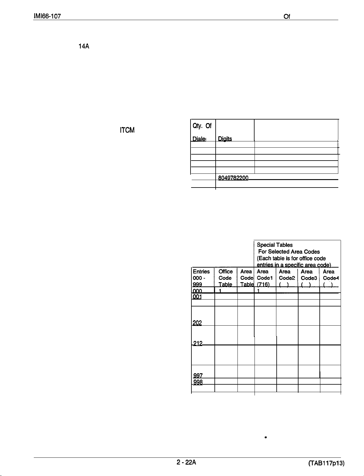
Description
System Features
Specialized Route Access
Software release 14A provides a specialized route
access feature that, when enabled, allows the system
to select a line group based on the digits the user has
dialed. By doing this, it matches calls with their best
suited routes. The feature provides a table-driven
After digit evaluation the system routes the call as
per the following discussion: If there is a special
table that matches the dialed area code, the system
searches that table for the dialed off ice code and
finds a line group. If there is not a special table for
that area code, the system just searches the area
code table for it and finds a line group.
routing scheme where the numbers that users dial
cause the system to chose a line group after
comparing the dialed number with entries that are
contained in an office code table, an area code table,
and four special area code look-up tables.
The following information illustrates the digit evaluation
scheme.
The specialized route access operates in the following
manner: When the caller presses ITCM and dials 9 or
Digits Dialed
presses a preprogrammed button, the system returns
a special dial tone. The caller then has 10 seconds in
which to dial some digits; otherwise, the telephone will
return to its idle state. Once a caller begins to dial
digits, he or she has a certain period of time in which
to dial each new digit. The system programmer
selects this time-out period through programming.
After the caller has stopped dialing digits and the end
7 67 067
3 116 118
4 5173
7
8
10
11
of the time-out period has occurred, the system
analyzes the dialed digits and routes the call by
following the table-driven routing scheme depending
upon how the programmer has arranged the system.
The system routes calls based on comparison
matches between the dialed number and the entries
The example below shows how calls to area code 202
are routed using line group 2, calls to office code 202
are routed using line group 1, calls to office code 973
in area code 716 are routed using line group 4, and all
other calls are routed using line group 1.
that it finds in either an office code table, an area code
table, or four special tables for selected area codes.
These tables contain 1000 entries from 000 to 999 and
the programmer can assign one line group to each
entry; therefore, a routing match is always possible.
The system matches dialed digits with table entries in
the following manner:
l
If the first digit that the caller dials is neither a 1 nor
a 0, and if he or she dials less than 10 digits (such
DO7
as : nnn-nnnn), the system evaluates the first three
digits as an off ice code, searches for the off ice
code in the office code table, and finds a line group,
Actual
. .
d
9787700 978
19787700 978
1804.978
18849782200 1804,978
1 1
1 1
1
7
Digits Evaluated By System
To Find Line Group
517
t
1
If the first digit is either a 1 or a 0 (such as:
n-nnn-nnnn), the system ignores the first digit and
evaluates the next three digits as an office code,
searches for the office code in the office code table,
and finds a line group,
l
If the first digit that the caller dials is neither a 1 nor
a 0, and if he or she dials 10 digits or more (such
as nnn-nnn-nnnn), the system evaluates the first
three digits as an area code and the following three
digits as an office code.
If the first digit that the caller dials is either a 1 or a
0 (such as n-nnn-nnn-nnnn), the system ignores
the first digit, evaluates the next three digits as an
area code, and evaluates the following three digits
as an office code.
1
973
1
1
1 1
1
999
1 1
Specialized Route Access
1
4
1
continued on next page . .
Page 45

Description
System Features
Specialized Route Access
The programmer can arrange for the system to insert
up to six digits ahead of a dialed number for a selected
line group. This feature is useful if the dialed number
must match a specific common carrier format.
To help understand this digit insertion, review this
typical arrangement for transparent CENTREX
operation (This example assumes that the CENTREX
extensions do not conflict with the office codes.): With
the digital telephone system installed behind a
system, callers can make outgoing calls
without having to dial 9. Assume that the CENTREX
extensions are 3300 -3399. Take programming action
to assign line group 2 to entries 330
code table. This means that calls on CENTREX
extensions will use line group 2 and all other calls will
default to use line group 1. Program the 9 digit as the
insertion digit for line group 1. With this set up, when
a caller dials a number other than a CENTREX
extension, the system automatically inserts a 9 ahead
of the dialed digits and routes the call over line group 1.
If no lines are free in a selected line group, the system
will route the call to an overflow line group if the
programmer has assigned one; otherwise, the system
will return busy tone to the caller.
continued
339 in the office
NOTE:
Using Specialized Route Access For Simplified
Toll Restriction
In anticipation of the implementation of the revised
North American dialing plan, the SRA feature
provides the system with the ability to deny calling to
designated area or off ice codes. The programmer
merely assigns a line group that contains no assigned
lines to the designated office or area code. This
prevents the system from routing calls for dialed
numbers containing those particular area or office
codes since there is no line available. This action will
work only for manually dialed numbers because
automatically dialed numbers, with no line preselect,
employ the last used line and therefore cannot be
restricted.
the programmer has arranged for the system
to insert digits on a particular line group, he or
she should consider arranging for the system
to insert digits in the overflow line group as
well. This consideration is necessary only if it
is important for the call to route through the
same common carrier as was the original line
group.
(TAB1 17~14)
Page 46

Description Of System Features
Subdued Off-Hook Voice Announce
With the secure off-hook voice announce (SOHVA)
feature, a user can make a secure announcement
from one station to another station that is off-hook and
busy on a call. A station being operated in a
handsfree mode cannot receive a SOHVA. With
SOHVA, the caller delivers the call and the user
receiving the call responds to it in a secure manner
that prevents the distant party from hearing either the
announcement or the response. The system
precedes the announcement with a tone alert that it
delivers to the handset receiver of the called
telephone. It also supplies a tone to the announcing
caller to alert them that they are making a SOHVA call.
A user can respond to the SOHVA announcement
either verbally or non-verbally. He or she either
effects a verbal response by pressing and holding the
MUTE button and speaking into the handset or effects
a non-verbal response by pressing a pre-programmed
button to send a message to be shown on the display
of the announcing station (if it is an LCD
speakerphone). The system automatically
disconnects the announcing station after it delivers the
response message to it (and displayed if an LCD
speakerphone). Stations that have the voice
announce blocking feature turned on cannot receive a
SOHVA. A programmer can use station class of
service programming to disable the SOHVA feature at
a station port if desired.
group to each station port to allow or to deny SOHVA
receive and/or originate capability to it. By properly
assigning SOHVA groups to station ports, the
programmer can open or block SOHVA paths between
stations.
SOHVA groups are
following configurations:
. .
SOHVA
OHVA
.
.
s
to
anv
by the system into the
.
.
.
Off-Hook Voice Announce Originate
This feature allows a telephone user to program a
button at his or her station that she or he must press
before delivering a SOHVA call. This SOHVA enabled
button allows a caller, after hearing a busy signal, to
decide whether to interrupt the called party in a
SOHVA manner. If the caller decides that the called
should be interrupted, the caller can press the button
and complete the SOHVA call. This button, along with
SOHVA groups, allows system users greater control of
the callers
of the situations in which they are allowed to make
them.
The programmer can program the ability of station
ports to originate and/or receive SOHVA calls by
assigning SOHVA calling groups to station ports. This
means that he or she can arrange certain station ports
together for SOHVA calling between one another while
excluding other station ports in the system from this
The system provides eight different SOHVA groups
that are fixed into a variety of SOHVA receive/originate
configurations. A programmer can assign one SOHVA
that
are allowed to make SOHVA calls and
Off-Hook Voice Announce (SOHVA)
The following examples may help you to understand
how to use SOHVA.
Example 1:
messages to all stations in the system and allow those
stations the ability to originate SOHVA messages to
each other but not to station port 10. Assign group 1
to station port 10 and assign group 2 to all other
station ports.
Example
and originate SOHVA calls between each other but
deny both receive and originate capability from any
other system stations. Assign group 8 to both station
port 14 and station port 15. Do not assign group 8 to
any other station port
The programmer assigns SOHVA groups using the
station class of service programming procedure.
Allow station port 10 to originate SOHVA
2: Allow station ports 14 and 15 to receive
be
sure
d to them
all
.
.
2
23
Page 47

Description Of System Features
Subdued Ringing
Refer to the discussion titled Ringing.
System Alarm Reports
The programmer can arrange the system to report
alarm and status conditions to a particular station or
stations that he or she has enabled to receive them.
The alarm receiving station must be an LCD
speakerphone. When a station is enabled to receive
alarms, its user can take appropriate action to cause
the alarm codes to be presented on the LCD display.
A programmer must use both system and station class
of service programming to enable this feature.
System Speed Dial
Refer to the discussion titled Automatic Dialing.
Tandem Attendant
When the programmer uses system class of service
programming to enable the tandem attendant feature,
a recall from an unanswered call transfer or a timed
hold recall will ring at the normal attendant station
(station 10) that set the transfer or hold condition, and
also ring at the tandem attendant station (station 12).
TAP (Flash/Recall)
If the host system provides custom calling features via
a hookflash signal, the programmer should program
the system so that the TAP button will generate a
“flash” signal when a user presses it. If custom calling
features are not available to digital telephone system
users, the programmer should program the TAP
button to function as a positive disconnect, dial tone
recall button. The flash and recall features are
mutually exclusive. The programmer uses the system
class of service programming procedures to set the
flash or recall TAP time.
Tenant Service
Refer to the discussion titled SquareIVon-Square
Configuration.
Timed Hold Recall
Refer to the discussion titled Ho/d,
Toll Restriction
Default Toll Restriction
The system defaults two toll restriction tables with
pre-programmed values and pre-assigned to all lines.
The programmer needs only to assign these tables to
the stations by programming action to put them into
effect. He or she can use the toll restriction table
configuration class of service programming to
reprogram the defaulted tables wlth different
information as needed.
Flexible Toll Restriction
A system programmer can configure system toll call
restriction to prohibit some or all stations from calling a
wide range of number combinations. The restricted
numbers are specified on up to 16 tables. The system
assigns several broad-range values to two of these
tables, and assigns the tables to all lines as a default
condition. The programmer needs only to enable the
default tables on a per station basis to activate the
default toll restriction.
In general, toll restriction works as follows:
The programmable tables of restricted numbers can
contain up to four entries and each entry can contain
up to 16 digits.
A programmer programs each table of restricted
numbers to be an “allow” table or a “deny” table with
entries in an “allow” table overriding entries in a “deny”
table. This arrangement allows the programmer to
enable exceptions to toll restriction. For example, he
or she can arrange the table entries so that the system
allows the dialing of
though it denies the dialing of all
numbers. A programmer can store a “match anything”
symbol (#) to represent any digit from 0 to 9 in the
individual entries thus providing him or her with a
broad range of number combinations to choose from.
The programmer can individually assign the
programmed toll restriction tables to each appropriate
station and line. Therefore, when an outside call is
dialed, the system examines the dialed number and
makes a comparison between it and the toll restriction
tables. Any tables that the programmer assigned to
BOTH the station being used and the selected line
determine the restrictions to be imposed; It should be
noted that the system will automatically disconnect a
line from a station if its user dials a restricted number
on a restricted line from a restricted station.
Night Mode Toll Restriction
A programmer can assign toll restriction tables to any
or all stations in the system that will only take effect
when the system is in the night transfer (of ringing)
mode. These toll tables replace any that he or she
may have assigned to the station for normal, or day
mode, operation. For example: a programmer can
arrange for a station that has no other toll restriction
table assignment to receive a toll restriction table
which will restrict everything but local calls and will
only take effect when the system is placed in the night
transfer (of ringing) mode. Therefore, even though
users can make toll calls from this station during
daytime operation, they can make no toll calls from it
when the attendant programs the system for nighttime
operation using the night transfer of ringing feature.
numbers even
2-24
NOTE: Do
ringing) feature.
not confuse this night mode to// restriction
Page 48

Description Of System Features
Toll Restriction
Toll Restriction Override
Software release 14A provides users of the digital
telephone system with a toll restriction override (TRO)
feature. The TRO feature allows users to override the
toll restriction that they encounter at other stations with
their own station’s toll restriction assignments. In
programming for this feature, you create a four-digit
TRO code that users can dial to override the toll
restrictions of any station that they happen to be using
and replace it with a toll restriction that matches their
home station. After entering a TRO code, a user gets
his or her own prime line or idle line preference and its
accompanying toll restriction assignment. They then
have 15 seconds to dial an outgoing call. Once they
continued
hang up from a call, they have 15 seconds to make
another call without having to re-enter their TRO code.
The system marks outgoing line calls that users make
after entering a TRO code with a
prints is that of the overriding station and not the
actual station that the call was made from. If a user
transfers a TRO call or places it on hold and picks it up
at another station, the call belongs to the new station.
You can assign the TRO code through station 10 or
VDT programming and verify assigned codes using
the station class of service data printouts.
in its
(TAB1 17~3)
Page 49

Description Of System Features
Tone Or Voice Signalling (Intercom)
Refer to the discussion titled Intercom.
Transferring Calls
Refer to the discussion titled
Transfer.
Transfer/Conference Button
A fixed button is provided that gives quick, easy
transferring and conferencing.
Unanswered Call Transfer Recall Timing
Refer to the discussion titled Call
Transfer.
Voice Announce Blocking
Refer to the discussion titled Intercom.
Voice Mail Support
With software release revision 11 A, the digital
telephone system supports the use of voice
processing equipment connected to the system’s
station ports through the ATI-D analog terminal
interface. The ATI-D is a multipurpose
accessory for the digital telephone system. It has dual
circuits that allow the voice mail equipment to
interface to two station ports. In addition to the
required programming task of identifying the station
ports as voice mail ports, there are several other
programming considerations associated with voice
mail operation that the programmer can make
whenever their options are wanted. These options
include the following features:
With the automatic attendant feature, the voice mail
system automatically answers any line that is ringing
at a voice mail port. As a default, the system
automatically enables ringing line preference for any
port the programmer identifies as voice mail ports.
The programmer must choose a ringing assignment
for the lines assigned to the voice mail port before the
voice mail system can provide the automatic attendant
feature.
Automatic Transfer Of Voice Mail
The programmer can choose the immediate transfer
mode for voice mail transfers. However, if he turns on
the screen and/or confim-r options provided by the
voice mail system, he must not choose the immediate
transfer mode because it allows the system to transfer
a call as soon as it answers it precluding any screen
and confirm action that the voice mail equipment can
provide.
Hunt Groups
When a station port that has been assigned to a hunt
group is busy, a call to it will ring at the next idle
station port in the group. A call will try to ring every
port in a hunt group and if all are busy, the telephone
system will return a busy tone to the caller. A
programmer can assign all voice mail ports to a
circular hunt group to take advantage of its
multiple-port interface capability. With this
arrangement, a call will first try to ring at the first port,
then try.the.next one and so forth until it tries all four
ports.
Voice Mail Line ID
The programmer can program the voice mail lines with
identification (ID) numbers that allow the voice mail
equipment to identify which line it is answering. The
ID numbers that the programmer assigns’ here must
match the ID numbers that are selected as part of
voice mail system programming.
Voice Mail Transfer On Busy
The programmer can arrange the telephone system to
alert a busy telephone that the voice mail equipment is
attempting to transfer a call to it. Without this
programming, the voice mail equipment will
automatically route the call to a voice mail box when it
encounters a busy signal. With this option, when the
voice mail equipment tries to transfer a call to a station
that is busy on a call (outside or intercom call) and the
station has an available intercom line (stations can be
programmed to have a second intercom), the intercom
will ring subdued. The user can answer the call by
pressing the button of the ringing intercom line. In
general, attendants will probably desire this feature so
they can handle multiple calls, while other station
users may prefer to have a message taken when they
are already busy on a call.
Refer to the discussion titled Paging.
Zone Paging (Via Station Speakers)
2
25
Page 50

Chapter 3
Installation
Installation
Mounting Considerations
The common equipment cabinet should be attached
vertically to any sturdy, flat surface. It may be
vertically rack-mounted if desired.
Because of the current listing requirements of UL
1459, the length of the AC line cord on the
equipment cabinet is a maximum length of 5 feet;
therefore, the cabinet must be located within four
feet of-a proper electrical outlet. The system
requires a dedicated 117VAC 15 AMP circuit, with a
third-wire ground, supplied to a standard electrical
outlet (NEMA 5-l 5R).
The distance between the common equipment and
the TELCO/PBX jacks must be 25 feet or less as
per FCC requirements. A nominal distance of 7 feet
is recommended.
The mounting location must be secure and dry and
have adequate ventilation. The temperature range
of the location must be within 32-122 degrees F
(O-50 degrees C), and the relative humidity must be
less than 90 percent non-condensing.
Screwdriver
Electric drill
Connecting tool
connector block.
Crimping tool
Volt/Ohm Meter
Installation Notice
Per The Underwriters Laboratories standard 1459,2nd
edition, be aware of the following precautions when
installing telephone equipment that is to be directly
connected to the telephone company network:
Never install telephone wiring during a lightning
storm.
Never install telephone jacks in wet locations unless
the jack is specifically designed for wet locations.
Never touch uninsulated telephone wires or
terminals unless the telephone line has been
disconnected at the network interface.
to match fasteners
if prepared holes are required
for fastening wires to a type-66
for 623-type modular plugs
If the mounting surface is damp or if it is concrete or
masonry material, you must attach a backboard to
the mounting surface to be used for common
equipment mounting. Suitable mounting
backboards are available commercially or can be
constructed out of
Special Mounting Consideration
When battery back-up is part of the installation, the
external batteries and cable assembly (the Comdial
BBU02 battery back-up assembly), the common
equipment, and all wiring connections must be located
in a dedicated equipment room (as defined in the
National Electric Code published by The National Fire
Protection Association, Quincy MA, 02269). However,
the Comdial model BBL02 anf BBL03 battery back-up
assemblies consist of a closed metal cabinet, a pair of
batteries, panel-mounted fuses, and a cable that
connects the battery back-up unit to the common
equipment. This cable is secured to the cabinet by a
strain-relief. These models are safe for installation in
general office environments and do not need to be
installed in a “dedicated equipment room.”
Tools And Hardware
Fasteners
toggle bolts, or -wall anchors
wood screws
plywood cut to size.
x l-inch round head),
l
lines.
Simplified Hybrid Operation
In the past, the Federal Communications Commission
(FCC) required that telephone system manufacturers
provide a hardware strap that installers could move to
distinguish between hybrid system and key system
operation. Prior to the release of software revision
1 IA, the digital telephone system provided this strap
at either the Jl station connector or at a special
terminal strip (depending upon the system model).
The installer strapped two terminals together at either
the 66M-xx station connector block or at the special
terminal strip to select the hybrid mode. Recent
rulings by the FCC have eliminated the need for the
hardware strap. Beginning with software revision
whenever a programmer assigns lines to line groups
the digital telephone system automatically assumes
the hybrid mode and the system no longer includes a
hardware strap that the installer must move. The
hybrid system mode may incur a higher monthly tariff
to the telephone company; therefore, the FCC requires
that the installer report the equipment-type category
designation number (KF for key system, MF for hybrid
system) to the telephone company at the time of
installation.
Use caution when installing or modifying telephone
3-l
Page 51

Mounting Procedure
1.
Unpack and carefully inspect all equipment for
shipping damage. Notify the shipper immediately
of any damages found. Verify that the packages
contain all parts and accessories needed for proper
installation and operation.
2.
If a backboard is required at the mounting location,
attach it securely to provide a stable mounting
surface for the equipment.
3.
Refer to Figure 3-1 or to the PPO32-000 mounting
template included in the literature that
accompanies the common equipment cabinet for
the locating dimensions required for the three
mounting screws, and mark their locations on the
mounting surface.
4.
Drill holes in the mounting surface of a proper size
to accommodate the hardware being used. If
necessary, prepare these holes with inserts,
anchors or other attachment devices as dictated by
the type of mounting surface.
5.
Insert the two top screws into the mounting surface
and tighten them to within approximately
of the surface.
6.
Hang the cabinet on the top screws using the
mounting holes located on the rear of the cabinet.
Note that these holes are elongated with an
enlargement at one end. This feature allows the
cabinet to snap down on the screws to secure the
mounting when the cabinet is hung on them.
7.
insert a third screw through the mounting tab
located on the lower edge of the cabinet and into
the mounting surface, and tighten it into place.
a.
Place the individual telephone stations as desired
and in keeping with accepted industry and off ice
standards. A telephone station can be wall
mounted if necessary as they are desk/wall
reversible. Refer to Chapter 6, Maintenance, for
instructions in preparing a desk/wall reversible
station for wail mounting.
3-2
Page 52

Page 53

Installation
AC Power Connection
Employ a dedicated 117VAC 15 AMP circuit, with a
third-wire ground, supplied to a standard electrical
outlet (NEMA 5-15R) for the AC power connection.
AC power connection is illustrated in
shown below.
For added equipment protection, connect a plug-in
power line surge protector between the power cord
and the AC outlet.
Figure 3-2
installation in general off ice environments
not need to be installed in a “dedicated equipment
room.”
The minimum battery backup time for a fully
configured system can be calculated. The formula for
doing this is:
T
Thoroughly check out the installation before
connecting the power cord to an electrical outlet to
apply AC power to the system.
Battery Back-Up
The common equipment provides an interface
connector for the connection an optional external
battery assembly. Several different assemblies are
available separately as kiis (product codes BBU02,
BBL02,
Be sure that the AC power cord is
connected to the electrical outlet before
connecting an external battery assembly to
the common equipment interface
connector. This ensures that internal
protection circuitry is operating to prevent
damage that could result from improper
connection.
The optional external battery assembly provides a
minimum of one hour of operation should the AC
power to the system be interrupted. The BBU02 and
BBL02 assemblies have a 15 ampere-hour current
rating and the BBLOB assembly has a 25 ampere-hour
current rating.
The BBU02
may include batteries from either of the following
suppliers:
Model PS-12150 from Power-Sonic Corporation,
Redwood City CA, 94032
Model
City Of Industry CA, 91748
The BBL03 external battery assembly may include
batteries from the following supplier:
Dynasty JC12-250 from Johnson Controls Inc.,
Milwaukee WS, 53212
As discussed previously in the page 3-1 paragraph
titled Special Mounting Consideration, you must mount
the BBU02 assembly, the common equipment cabinet,
and all the wiring in a “dedicated equipment room”.
The BBL02 and BBL03 assemblies consist of a closed
metal cabinet, a pair of batteries, panel-mounted
fuses, and a cable that connects the battery back-up
unit to the telephone system. This cable is secured to
the cabinet by a strain-relief. This model is safe for
and
BBL02 external battery assemblies
from GS
K
e = Ampere-hour capacity of battery (BBU02 = 15)
N = total number of stations
Example:
Assume that a Cl832 system plus two CM408
modules are installed along with a BBU02 battery
assembly to provide back-up power.
= 1 +
During AC operation, the common equipment
provides recharging current to maintain the voltage
potential of the external battery assembly at an
operational level. The charging circuit may not
provide an adequate charge if an installed battery
assembly has a current rating of greater than 40
ampere-hours.
NOTE: An optional external battery assembly requires
The common equipment cabinet has internal
secondary surge protection on all line ports. In order
for this protection to be effective, the cabinet
connected to a reliable earth ground such as a metal
cold water pipe or a building frame ground. The
grounding wire must be of
copper and separate from the three-wire AC line cord.
A ground stud is located on the common equipment
cabinet for this purpose. System grounding is,
illustrated in
If spare conductors exist in the cables that are run
between the station and the
it is good practice to connect them to earth ground.
Doing this may help prevent them from inducing radio
frequency and/or AC interference into the system. It is
also good practice to disconnect any unused station
jacks from the connector block and ground that wiring
to earth ground as well.
and
does
0.9 for GO408 with or without a GM408 module
0.8 for GO81 6 with or without GM408 modules
0.8 for G1632 with or without GM408 modules
(8.8)
approximately 10 hours to completely
completely discharged and, in some cases,
5)
when initially installed.
12
5.8
= 2.1
Hours
,
System Grounding
MUST
or #12 insulated, solid
Figure 3-2,
connector blocks,
be
3-4
Page 54
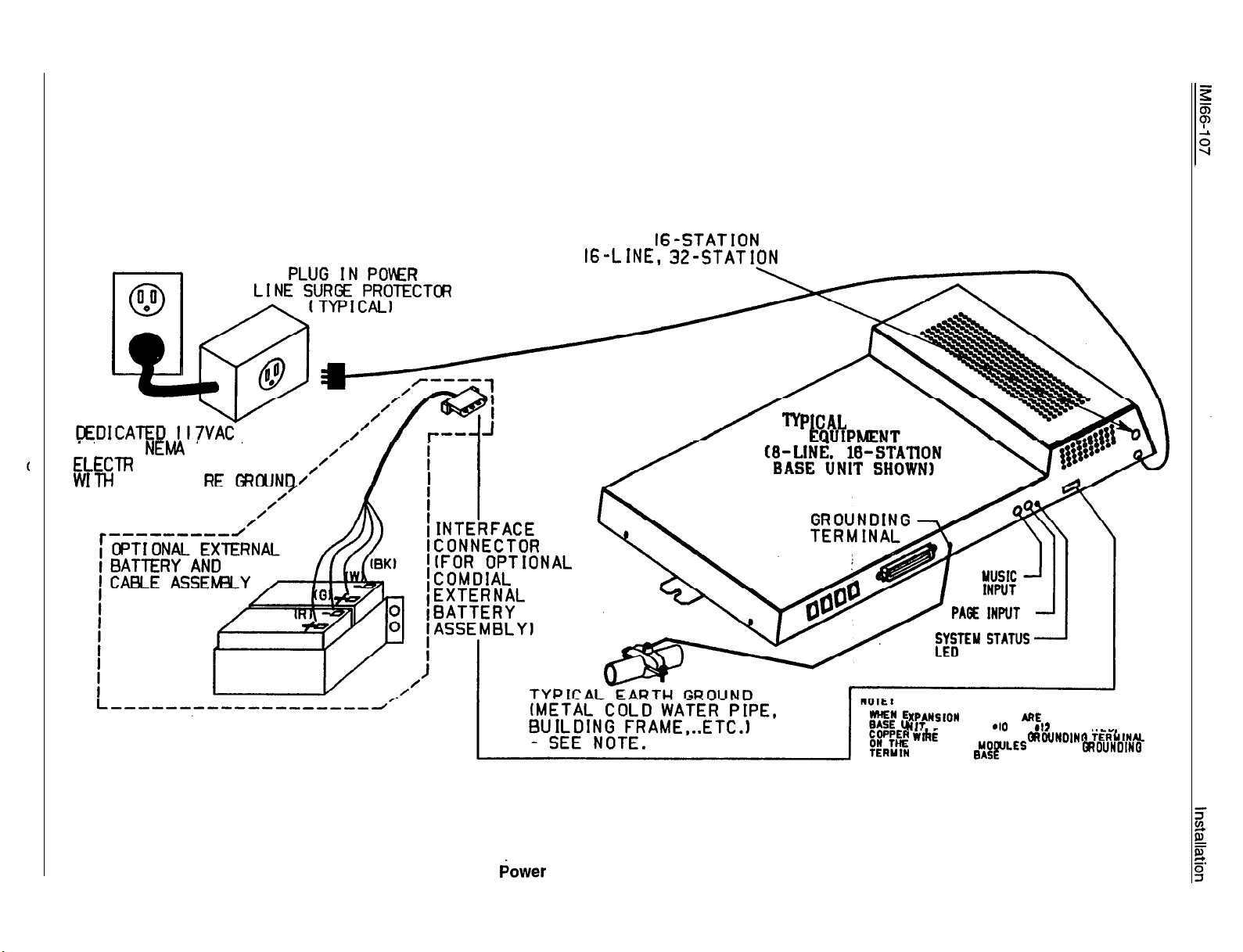
FUSE :
4-LINE, 8-STATION BASE UNIT: I AMP 250V SLOW BLOW FUSE
8-LINE,
BASE UNIT: 3A 250V SLOW BLOW FUSE
BASE UNIT: 3A 250V SLOW BLOW FUSE
COMMON
I 5 AM’
C
I CAL OUTLET
THIRD-WI
5-l 5R
Figure 3-2. AC Power Connection And System Grounding
ATTACH A
BETWEEN THE
EXPANSION
AL ON TM
MODULES
OR
UNIT
INSTALLED ON TM
INSULATED
AND THE
Page 55

Installation
Line Connections
The line terminations for the common equipment
cabinet are standard modular plug/jack connections.
Each modular jack provides termination for two lines.
Modular line jacks 1 and 2 also provide termination for
an auxiliary pair in addition to the two outside lines.
The outside line termination can be a type 66M-xx
connector block or individual 6-position modular jacks.
The line cord that is routed between the outside line
termination and the common equipment termination
should be twisted-pair wiring.
line connection details for all three of the common
equipment base units.
line connections. The G0406, GO61 6 and G1632
common equipment supports the installation of up to
4, 6, or 16 lines respectively. Add-on expansion
modules are available to expand the line capacity of
the systems.
After you have initially connected a line to a particular
line port and programmed its attributes (or left it with
the system defaulted values), you can reassign the
line and its attributes to a different port by
programming action if you wish. This feature allows
you to make adds, moves, and changes without
relocating the line wiring. Refer to Chapter 4 for the
line to line port reassignment programming details.
Figure
Table 3-I
shows the
Transient voltage spikes, if induced onto CO or
the common equipment. The telephone company
offers basic protection against this condition but it is
usually designed to protect the central office circuits.
While it will also provide some protection to the
common equipment, it should not be relied upon for
total protection. To help ensure that external
overvoltage surges do not damage the system, the
manufacturer recommends that gas discharge tubes,
or similar primary protection devices, be installed and
properly grounded on all lines (a selection of
solid-state protection devices for this purpose is
available from ITW Linx, Elk Grove Village, Illinois
60007).
Line Grounding
3-6
Page 56

Table 3-1. Line Connections
Installation
4 Line, 8 Sts. Base Unit
8
Line, 18 Sts. Base Unit
18
Line, 32 Sta. Base Unit
Line, 18
Une, 32 Sta. Unit
Unit
CONNECTION
Auxiliary 1 (Line 2) TIP
Line 2 TIP
Line1TIP
1
RING
Line
2 RING
Line
Auxiliary 1 (Line 2) RING
Auxiliary 2 (Line 4) TIP
4 TIP
Line
Line
3 TIP
3 RING
Line
4 RING
Line
TELEPHONE NUMBER
6 Line, 32 Sta. Base Unit
4
5
6
7
1
2
3
4
No Connection
Line 14 TIP
Line 13 TIP
Line 13 RING
Llne 14 RING
6
6
1
2
3
No Connection
No Connection
Line 16 TIP
Lint! 15
Line 16 RING
No Connection
Line Connections
Continued on next page. . .
Page 57

Base Unit
Line Jacks 1
Aux. Line 2
Line Jacks 3
Aux. Line 4
Line Jacks 1
2
4
::::::::::::
. . . . . . . . . . . .
\ \
Grounding
Terminal
Line Jacks 9
Line Jacks 11
Line Jacks 13
Line Jacks 15
,
. . . . . . . . . . . . o
4
10
12
Base Unit
Aux. Line 2
Line
Jacks 3
Aux. Line 4
Line Jacks 5
Line Jacks 7
‘Grounding
Terminal
4
6
8
. . . . . . . . . .
. . . . . . . . . .
. . . . . . . . . .
Terminal
Figure 3-3a. Common Equipment Line Connections
Page 58

66-083
Installation
--
3-9
Page 59

Installation IMl66-107
Station Connections
The digital telephone system supports the operation of
the following proprietary digital station types:
Multiline Telephones
LCD Speakerphones
DSS/BLF Consoles
Single-Line and Multiline Proprietary Telephones
Software Revision Considerations
A digital telephone system when equipped with Snnnn
software cartridges at any software revision level
provides support for the following DigiTech
telephones: product code 7714X, 7714s and 7700s
with a revision letter of A through H. At software
release 8, support was added for the DigiTech DD32X
Wiih the Snnnn software cartridge at software release
10, the digital telephone systemalso supports the
newer DigiTech telephones with a product code
7714X,
later. You need to consider the following items when
installing the revision I and later telephones.
While the system when equipped with an Snnnn
cartridge at software release 10 and later supports the
use of all DigiTech telephones regardless of their
revision letters, a system with an Snnnn cartridge at
software release of
revision I and later telephones. In other words,
whenever a system includes revision I or later
DigiTech telephones, be sure that the system software
release is at 10 or later.
Always program station ports to provide ringing line
preference to revision I and later telephones that are
connected there. This action is necessary before the
orange LED feature can become active.
and 7700s at a revision letter of I and
or earlier will not support the
provided for all DigiTech and Impact telephones.
Station Installation
The G0408, GO81 6 and G1632 common equipment
supports the installation of up to 8, 16, or 32
telephones respectively. Add-on expansion modules
are available to expand the station capacity of the
systems.
Connections between the common equipment and the
stations are typically via type
which are cable connected to the common equipment
turn, wired to modular jacks that accept the modular
line cord connected between it and the telephones.
The maximum distance allowed from the common
equipment to the stations is per the following list:
Multiline Telephones
twisted-pair cable or 2000 feet using #22 gauge
cable
Single-Line Telephones
gauge, twisted-pair cable
When installing the system telephones keep in mind
that each station port supports only one proprietary
telephone and the system does not allow you to bridge
two stations to a single modular jack.
Grounding Considerations
Remember, if spare conductors exist in the cables that
run between the stations and the
blocks, it is good practice to connect them to earth
ground. Doing this may help prevent them from
introducing radio frequency and/or AC interference
into the system. Also remember that it is good
practice to disconnect any unused station jacks from
the connector block and ground that wiring to earth
ground as well.
connector blocks
1000 feet using #24 gauge,
1500 feet using #24
connector
With the Snnnn cartridge at’software release 11 A, the
digital telephone system provides support for the
proprietary single-line digital telephone (product code
7701 X).
With software release 128 in lnnnn software
cartridges, the digital telephone system provides
support for all DigiTech telephones and DSS/BLF
console plus support for Comdial Impact telephones
and DSS/BLF console with product codes of 8024,
8012, 8112, 8101, and IB64X beginning with a revision
letter of A.
With software release 138 on lnnnn cartridges, the
8112N multiline
proprietary telephone and the Americom telephones
and consoles with product codes of 711 OX, 701 OS,
Station Relocation
The digital proprietary telephones identify their
telephone type to the system when you install them.
The system assigns an extension number and all other
programmable attributes to station ports as a default
that you can reprogram them as needed. Plus, you
can use programming action to reassign attributes of
one station port to a different station port if you wish.
This station relocation feature allows you to do adds,
moves and changes without relocating the station
wiring. Refer to the automatic station relocation
programming procedure and the station-to-station
programming procedure found in Chapter 4.
3-10
can not be relocated.
Page 60

Installation
Cable Clips
Each cabinet-mounted 50-pin male connector is
equipped with a retaining clip. This clip is designed to
secure the mated connection once it is made. The clip
does this by snapping into a slot on the cable-mounted
connector when it is pressed together with the
cabinet-mounted connector. This retaining clip must
be pulled back slightly to unsnap it before the
connectors can be separated.
particular enable button that he or she has
programmed, that device is the one that is active and
named in the display.
If an external device requires power for its operation,
you must install an external source to supply it. The
system does not supply any power through the
telephone’s auxiliaryjack. The auxiliary jack is an
audio output source for the external ringer, external
paging device, and tape recorder. The jack will accept
an audio input signal from the headset microphone
Auxiliary Jack
product code of 80248 and
rev I and later)
during headset operation but it is not designed to
receive signals from any other external device or from
a telephone line.
The auxiliary jack (available on impact 80248 and
DigiTech 7700s Rev. I and later LCD speakerphones)
will support the use of the following devices: a
headset, a tape recorder, an external ringer, or an
external paging device.
The auxiliary jack is a 4-position 616~type handset jack
that provides the following connections:
positions 2 and 3 = output from system
to external device
positions 1 and 4 = input to system from
headset’s microphone
If a user needs to connect a tape recorder to his or her
telephone’s auxiliary jack, you must obtain a special
At any given time, the auxiliary jack will serve
whichever external device that is listed in its display
recorder cable made for this purpose from your normal
distribution outlets:
but it will serve only one of those devices at a time.
The user must program a separate enable/disable
button for each external device that he or she plans to
Cl001
CD001
connect to the auxiliary jack. When a user presses a
With the exception of a headset
microphone, do not connect the audio
output of any external device to the
auxiliary jack. Also, do not connect the tip
and ring leads of a telephone line to the
auxiliary jack. Do not connect any devices
to the auxiliary jack other than those
mentioned in the telephone user’s guide.
You should caution the telephone users
about this fact as well.
3-11
Station Connections
Continued on next page . . .
Page 61

BASE
STATION
DATA PORT, STATION 17 AUDIBLE,
POWER FAIL STATION,
COMMON AUDIBLE,
STATIONS 1 O-25
(O-LINE,
STATION 17
AUDIBLE
COMMON
AUDIBLE
BASE
POWER FAIL STATION
MUSIC INTERFACE
PAGING PORT
SYSTEM STATUS LED
BASE UNIT
STATION10
DATA PORT, STATION 17 AUDIBLE,
POWER FAIL STATION,
25, COMMON AUDIBLE,
Figure 3-4a. Common Equipment Station Connections
Page 62

Page 63

Installation
Table 3-2. J-1 Station Connections
Base Unit)
SPARE
PORTS
Station Connections
Continued on next page . . .
Page 64

Installation
Table 3-3.
(&Line,
Station Connections
Base Unit)
Station Connections
Continued on next page . . .
Page 65

Installation
Table
Station Connections
Base Unit)
3-16
SPARE
PORTS
Station Connections
Continued on next page . . .
Page 66

Installation
CABLE CONNECTIONS
N
E
I-GREEN
N
Table
CLIP
4 29
4
11
7 32 13
7 14
8
33
15 SIGNAL
8
16
9 34 17
9 18
Station Connections
Base Unit)
P-WIRE CONNECTIONS
1
7
8
9
SIGNAL
PATH
GREEN
GREEN 32
RED
GREEN 33
PATH
RED
SIGNAL
PATH
.
STATION CONNECTIONS
I
K-BLUE
YELLOW-GREI
YELLOW-BROWN 19 1 44
BROWN-YELLOW
20 45 39
SLATE
I-YELLOW 20 40
VIOLET-BLUE
21
BLUE-
_
19
21
38
41
I
SPARE PORTS
VIOLET-SLATE
SLATE-VIOLET
ET
’
1 48
25 50 I 49
25 I 50
I
Page 67

Installation
Station Wall Mounting
The
(product code 8nnnn) telephones are shipped from the
factory configured for desk use. To convert them for
wall mounting, follow the procedures outlined below.
Americom telephones (product codes 70nnn and
71 nnn) are standard desk telephones. They require
an optional bracket for wall mounting purposes. Order
either the
or the
through your normal distribution channels.
To convert the model 77nn telephones for wall
mounting,
1.
Disconnect line cord and handset cord from
telephone.
2.
Turn telephone over to ex ose lower housing.
The telephone circuitry is sensitive to
static electricity discharge. Be sure that
your body and the workplace are properly
grounded to avoid any static electricity
discharge while step 3 is being performed.
3.
Remove screws that attach lower housing to upper
housing. Carefully separate lower and upper
housings making sure not to disconnect wiring
between them.
4.
Carefully reverse lower housing end-for-end (rotate
it 180 degrees). Do not disturb any internal wiring
during this process.
5.6.Refasten lower housing to upper housing.
Make sure that all wires are clear-Do not
over-tighten screws while refastening the housings.
Route line cord through appropriate channel on
lower housing, and reconnect it to telephone.
Substitute a short line cord for standard supplied
one if desired.
7.
Reconnect the handset cord.
(product code 77nnn) and lrnpacr
OX-BK bracket (for
bracket (for 164ine telephones)
O-line telephones)
To convert the Model 80nn And 81nn telephones
for wall mounting
1.
2.
3.
4.
5.
There are wall mounting enhancement kits available
through your normall distribution channels. These kits
include a handset cradle cup that you can
screw-mount to the telephone’s upper housing. The
product codes for these enhancement kits are:
for the lmpacr telephones (product codes 80nnn and
codes 77nnn) and HCCA for Americom telephones
(product code 70nnn and 71 nnn).
To wall mount the telephones,
After configuring a telephone for wall mounting either
mount it directly on the wall using two
screws (obtained locally), or mount it on a wall jack
cover plate. If using a wall jack cover plate, use an
AT&T type 6308 wall plate for best results.
1.
2. Position the keyhole-shaped holes in the bottom of
Turn telephone over and disconnect line cord and
handset cord from telephone. Do not damage line
cord on plastic dressing tabs.
Remove screws from pedestal and unlatch it from
telephone housing, rotate it end-for-end (180
degrees), relatch its tabs in the slots in the lower
housing of the telephone, and replace screws.
Route line cord as appropriate, and reconnect it to
telephone. Substitute a short line cord for standard
supplied one if desired.
This telephone provides a reversible handset
retaining hook. When wall mounting, pull up this
hook and rotate it -180,degrees from its desk-use
orientation
Reconnect the handset cord.
If #IlO screws are used, thread them into the wall
within 1/84nch of the surface. Refer to
for the spacing dimensions.
the telephone over the
plate studs. Slide the telephone down until a slight
click is felt.
(see Figure 3-5b).
panhead
Figure 3-5~
0 screws or the cover
3. To remove the telephone, lift to unsnap both
screws or studs from the bottom housing, and then
lift it away from the wall.
3-18
Page 68

Remove lower housing,
degrees
Figure 3-5a. Reversing The Lower Housing
On Model 77nn Telephones
Installation
NOTE:
Wall Plate
for secure mount.
OR Screws
wall
0
is
--
3
Pull
up sprinpbaded
handset wall tab,
180
and rekase.
Figure 3-5b. Reversing The Pedestal And Handset
.
Hook On Model 60nn And 81 nn
Telephones
Figure 3-5~. Station Wall Mounting Details
3-19
Page 69

installation IMl66-107
Console Installation
Beginning with software release 8, the digital
telephone system supports the installation and use of
a DigiTech DD32X and an Americom
console to a station that already has a paired console
installed with it.
The digital telephone system automatically recognizes
a console when you connect it to a station port and
automatically assigns the station intercom numbers to
software release 12A, console support is extended to
include the impact IB64X console as well. The
number of installed consoles is limited only by port
availability; however, since a console complements a
companion telephone located in an adjacent station
port, you can use up to one-half of the available
station ports for consoles. In addition with the dual
the console buttons for direct station selection (DSS)
purposes with associated busy lamp field (BLF) status
lights. However, the console buttons are fully
programmable and the station user can customize
them as he or she see fit by programming them as
DSS buttons or as automatic dialing (autodial) buttons.
When the user programs the buttons for DSS use,
console feature (discussed later), a full two-thirds of
the total station port capacity is available for console
use.
level at each DSS button. All 32 buttons on the DD32X
console and the first 48 buttons on the
Beginning with software revision of 9, you can assign
two consoles to one telephone. This feature is
especially useful when used with DigiTech DD32X
consoles and a G1632 system that has one or two
GM408 expansion modules included with it. This dual
console feature allows a station user to monitor up
to
48 stations from one station location using 32-button
While the first
logic-paired port) extends the autodial buttons of the
paired telephone by 32 and provides DSSIBLF
coverage for station ports 10 through 41, the second
station port) provides DSS/BLF coverage as follows:
consoles.
Install the first console at the station port that is
logic-paired with the station that you wish to
complement. Install the second console at any station
port except 10 or 11 and, using class of service
programming, assign it to the same station port that is
logic-paired with the first console.
The digital telephone station ports are logic-paired as
follows:
11
12-13
14
15
16
17
18-19
20
21 36
22-23
24-25
26-27 42-43
28-29
30
31
32
33
34
35
37 52
38
39 54
40
41 56
44-45
46
47
48-49
50
51
53
55
57
On a 32-station system with two 8-station expansion
modules, the first 16 buttons are automatically
assigned (defaulted) to station ports 42 through 57
for DSS purposes.
On a 32-station system with one 8-station
expansion module, the first 8 buttons are
automatically assigned (defaulted) to station ports
42 through 49 for DSS purposes.
On any other smaller station capacity system, all
buttons are unassigned.
When you install a console and program it to
complement a telephone without first having a console
installed at a port that is logic-paired to that telephone,
its button assignment is automatically defaulted, as
described above, but the user can reprogram it as
required. It is important to remember that when you
You can install a DD32X, XD64X, or IB64X console at
any station port and assign it to a station without first
installing a console at the station’s logic-paired port if
you wish. This configuration is convenient for adding
a console to an existing telephone installation that
already has its logic-paired port occupied; however, do
not use this configuration for assigning a console to
station ports 10 and 12 because the console buttons
will not be usable for programming. As discussed
above, this feature is also useful for adding a second
program for a second console, the system sets the
console button mapping to that which is described
above. When you clear the assignment, the system
resets the button mapping to match a logic-paired
console. This means that when the second console
feature is cleared, the console installed at that port
complements the telephone that is installed at its
logic-paired port instead of the telephone that is
located at the program designated port, and its buttons
are automatically reassigned to station ports 10
through 41 (through station port 57 with
and
console (the one installed at the
console (the one installed at the programmed
and
consoles).
3-20
Page 70

installation
In addition to the DSS support that the consoles
provide to the telephone, the first DD32X console
provides COS programming buttons Cl0 through C41
programming purposes
complete program button coverage.
Refer to
and the second console provides COS programming
buttons C42 through C57 when they are needed. You
will not need the second IB64X or XD64X consoles for
Figure
since the first one provides
3-6 for an illustration of a typical
Typical
Telephone
CUP
Console
Figure 3-6. Typical DSWBLF Console Connections
Page 71

Installation
Power Failure Station Connections
The system provides a tip and ring pair connected to
line 1 as an emergency power failure circuit. This
circuit is active during a commercial AC power failure if
an external battery assembly is not installed to provide
battery back-up power to the system. Connect an
provide communications capability until the
to the system is restored.
The power failure.pair is located as follows and as
detailed in
NOTE: The system also provides one power failure
industry standard, single-line telephone, such as a
model 2500, to a power failure pair.and use it to
POWER FAILURE TERMINALS ON
STATION CONNECTOR BLOCK
8-STATION AND 8-LINE,
34 --l--
35 --l--
--l-37--i-36
TYPICAL INDUSTRY STANDARD
NON-ELECTRIC TELEPHONE
(POWER FAILURE INTERFACE1
--l--
40 --l--
41----c42--t-43---I--
44 --I--
45 --l--
46--l--
47 --I-46--I--
49--l--
SO--l--
CLIP TERMINALS
AC
power
Figure 3-7
below.
connection with each add-on expansion
module.
BASE
POWER FAILURE JACK
BASE
Figure 3-7. Power Failure Connection
3-22
Page 72

Installation
Auxiliary Equipment Interface
You can connect an industry-standard telephone or
data device on a line ahead of the common equipment
if you wish. If you do so, the system can detect an
off-hook condition in the connected device and turn on
the line status light at the system telephones to
indicate that the line is busy.
and
Figure 3-8
connections.
below detail the auxiliary interface
Table 3-1
(on page 7)
NOTE:
Connection is across tip and ring of lines 2 and 4.
The system provides the auxiliary interface
connections at terminals
equipment line jacks 1 and 2.
When you are employing this auxiliary
interface feature, the line-to-line port
reassignment as discussed previously and in
Chapter 4 works as described except in regard
to line 2 and line 4. Line 2 can only be
reassigned to line port 4 and line 4 can only be
reassigned to line port 2
and 6 of common
Figure 3-8. Auxiliary Interface Connections
Page 73

installation
Common Audible And
Selected
Auxiliary Ringing Interface
You can use he relay closure dry-contact points for
controlling external audible equipment. These contact
closures track the pattern of the ringing for incoming
calls. The contacts are closed during the ringing
period and are open during the silent period.
A typical common audible connection is illustrated
on
Figure 3-9 .
Do not exceed a 1 amp at 24 volts (0.5 amp
at 48 volts) load on these control terminals.
If the load requirements exceed this limit,
connect the load through an external slave
relay. DO NOT CONNECT THESE
CONTROL TERMINALS DIRECTLY TO THE
LINE.
Outside Lines
Common audible terminals provide a dry-contact
closure whenever any of the outside lines that you
have connected to the common equipment ring with
an incoming call.
Station
relay closure whenever ringing is sent to station 17
or to a programmable destination. Use class of
service programming to choose either station
the paging port as the ringing destination. Refer to
Chapter 4 for details.
When you have programmed for station port 17
ringing, it is a common practice to use a
customer-supplied external device to provide loud
ringing and connected in a manner similar to the
common audible arrangement shown in
When you have programmed forpaging port
tinging, it is a common practice to use a
customer-supplied external paging amplifier
connected to the paring port to amplify and
broadcast the ringing tones sent to, the paging port
by the system . You can employ the relay closures
that appear at the ringing terminals to energize the
external paging amplifier during the periods when
the ringing tones are being sent if necessary.
Ports
7 audible terminals provide a dry-contact
17
or
Figure 3-9.
CAUTION
Do not connect a external paging amplifier
or any external ringing device to the
station port 17 connections.
NOTE: Refer to the following paragraph headed
for a discussion of
external paging amplifier connections and
function.
3-24
Page 74
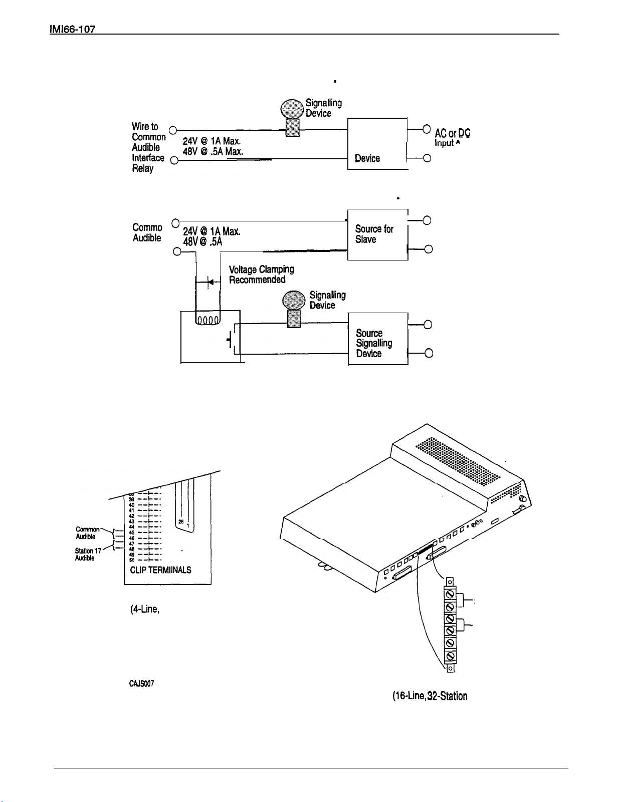
Installation
(Wiring shown for low current application
(Wiring shown with slave relay connection for high current application
Wire to
Interface
Relay
Slave
Relay
Max.
I
Diode
see caution text)
Power
Relay
Power
Source for
Signalling
Power
for
Required
see caution text)
ACorDC
Input as
Required
ACorDC
Input as
Required
,
Station Connector Block
E-Line, 1 E-Station Base Units)
Figure 3-9. Typical Common Audible Interface Wiring
3-25
Station 17 Audible
Common Audible
Barrier Strip
Base Unit)
Page 75

Installation
External Paging Interface
NOTE: This paging enable constant closure function
The system provides a special transformer-isolated
paging port that you can use to couple the system to a
customer-supplied external paging amplifier. This
external paging port does not provide a talk-back path
nor will it recognize DTMF dial tones.
You can use the relay closure dry-contact points that
the system makes available at the ringing port terminal
Connect the audio input of a customer-supplied
external paging amplifier to the paging port as
shown below in
for controlling the external paging amplifier during a
paging operation. These contacts close
closed during the time that a paging operation is active
to provide a constant enable signal path for the paging
and stay
If the paging amplifier requires an enable signal,
connect the enable leads to the station 17 audible
terminals as shown in
amplifier.
overrides the ring pattern closure provided
when ringing is sent to the paging port.
the previous paragraph titled
See
Figure 3-10.
Figure 3-10.
PA SYSTEM
mom,
TO RINGING PORT
TERMINALS IF ENABLE IS
REOU IRE
46-+-
STATION CONNECTOR BLOCK
8-STATION AND 8-LINE.
BASE
BARRIER STR IP
Figure 3-10. Typical External Paging Connection
STATION
BASE
AUDIBLE
3-26
Page 76
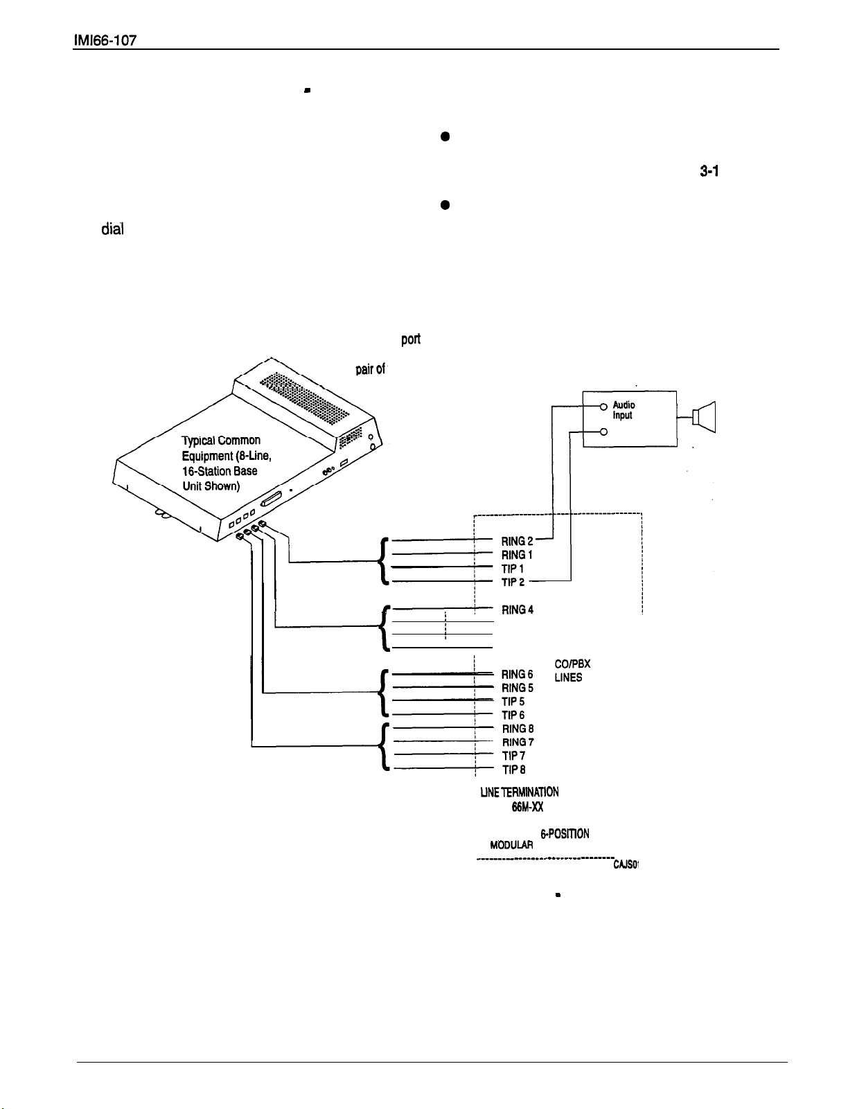
Installation
External Paging Interface
Line Port
You can use class of service programming to convert
a line port to be an AUXILIARY port. As an
AUXILIARY port, a user can use it to couple a
closure feature discussed previously is not available
for use with this installation.
Connect the audio input of a customer-supplied
telephone to an external paging device that you have
wired to the line port. He or she does this from any
station with that line presence by pressing the proper
line button to select the AUXILIARY port. The user
You can install a DTMF tone select, zone-paging
can dial DTMF tones or dial pulses through the
AUXILIARY port as needed. The paging enable relay
Program line port asProgram line port as
auxiliary
auxiliary
PA system to tip and ring
PA system to tip
that
and connect
and connect
and ring
port.
external paging amplifier to the tip and ring leads of
the AUXILIARY port as shown in
amplifier if you wish.
If do you install this type of
Figure 3-l 1
below.
amplifier, the user must dial the zone-select code
after he or she presses the AUXILIARY port line
select button.
PA System
TIP3
Figure 3-11. Typical External Paging Connection
RING 3
TIP 4
‘TYPE
OR
‘INDIVIDUAL
CONNECTOR BLOCK
Line Port
------
ii
3-27
Page 77
Installation
Data Device Connections
The system provides two RS232 Data Ports for use.
When you use a video display terminal (VDT) to
perform class of service programming, connect it to
RS232 Data Port A.
When you use a serial data printer for SMDR,
SMDA, and COS printout, connect it to the RS232
Data Port B.
When you use a Caller ID Interface (product code
CID08) to identify incoming calls, connect it to
RS232 Data Port B using the special cable provided
with the CID08. Refer to the paragraph titled
Identification Service Support (located on page
4-40) for installation details associated with this
feature.
The distance between a data device and the common
equipment can be up to 500 feet in a quiet electrical
environment. Some sites may require shielded cable
for long runs. For longer distances, you must install
limited distance modems to relay the data
communications between the common equipment and
a data device.
When preparing a cable for connection to a data
device, refer to the manufacturer’s manual for the
equipment being interfaced and make the following
wiring connections:
If required for proper operation, wire the common
equipment CTS (clear-to-send status from device to
common equipment) connection to the device RTS
(request-to-send) connection.
NOTE: The common equipment requires a positive
The default data communications format is as follows:
7-bit data with 2 stop bits and no parity
Baud rate of 300 baud
Configure a data device to match Jhis format for initial
operation or reprogram the system’s data format to
match those of a data device.
The system’s data ports are located as follows and are
connected as illustrated in
l
Clip terminals 37
(data port B) on station connector block.
TD = TERMINAL 37
RD = TERMINAL 38
CTS
SG = TERMINAL 40 TERMINAL 44
voltage, with respect to signal ground, in order
to send data.
Figure 3-12
40 (data
port A) and 41
on the next
Base Units
44
PORT
TERMINAL 41
TERMINAL 42
TERMINAL 39
TERMINAL 43
Wire the common equipment RD (data from device
to common equipment) connection to the device TD
(transmit data) connection.
Wire the common equipment TD (data to device
from common equipment) connection to the device
RD (receive data) connection.
Wire the common equipment SG (signal ground)
connection to the device SG (signal ground)
connection.
l&Line, 32-Station Base Unit
Special modular jacks are available as data ports
JACK
None
CTS
RD
TD 4
SG 5
None 6
1
2
3
Page 78

TO RS232
DATA
PORT
A
STANDARD
CORD
TYPICAL
INTERFACE
SHOWN FOR REFERENCE ONLY.
TO EIA ADAPTER
MODULAR JACK DATA PORTS
RS232
DATA PORT
NO CONNECTION
3
4
5
6
BASE
DATA PORT A
OF
NO CONNECTION
INDUSTRY STANDARD
MODULAR LINE CORD
Figure
NOTES :
TYPEN
SHOWN FOR REFERENCE ONLY.
TO
Typical Data Device Connections
MAXIMUM DISTANCE BETWEEN COMMON EQUIPMENT
CABINET AND PRINTER OR VDT TYPICALLY LIMITED
TO 500 FEET. LONGER DISTANCES
DISTANCE MODEMS AT EITHER END OF RUN.
2. SOME DATA
REQUIRE CTS SIGNAL FOR
LIMITED
OPERATION. ROUTE TO DEVICE AS
Page 79

Installation
Music Interface
If music is to be part of the system, connect a
customer-provided music source to the common
equipment music interface jack (phono jack) provided
for this purpose as shown below in Figure 3-13. The
impedance of this input is approximately 500 ohms.
Use the volume control on the music source to adjust
the audio level of the music as required.
MUSIC INTERFACE
Figure 3-13. Music Interface
MUSIC SOURCE
(FOR MUSIC ON
HOLD AND BACKGROUND
MUS
Page 80
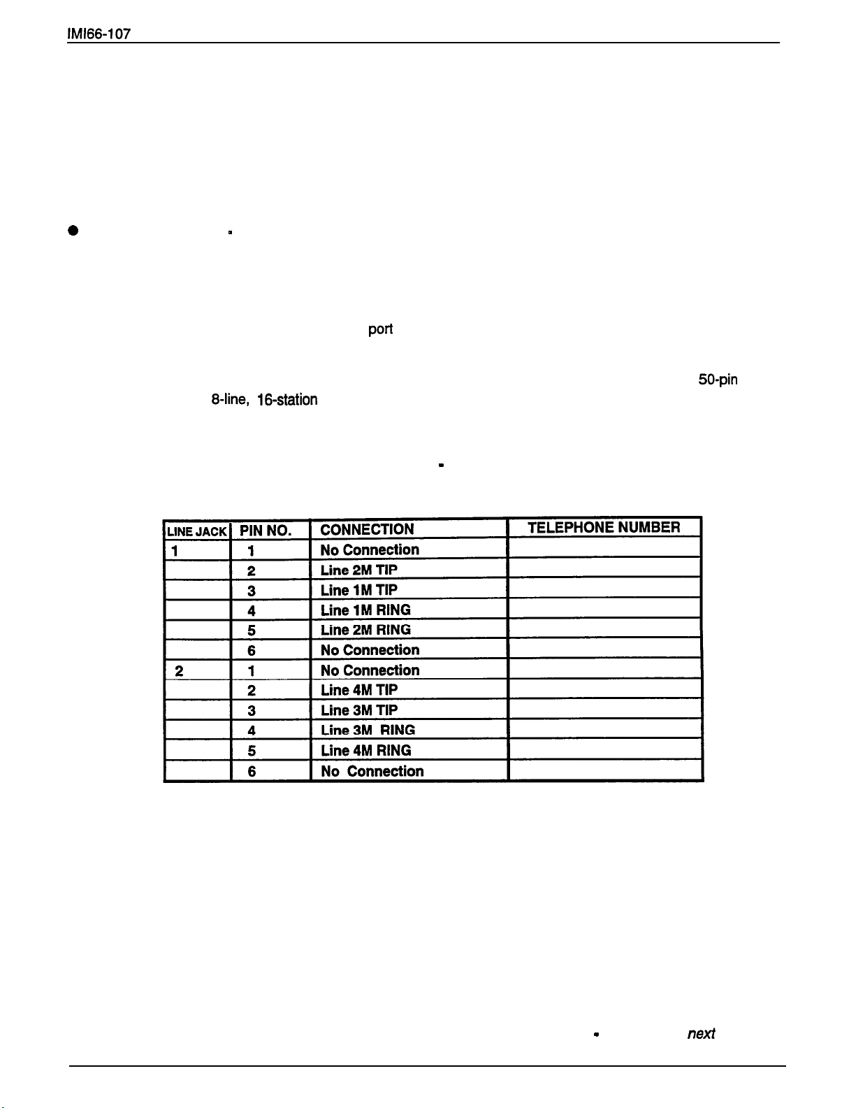
Add-On Expansion Module
Introduction
You can install one or two optional add-on expansion
modules on the common equipment base unit to
increase the line and station capacity of an installed
system. The add-on module is as follows:
408 Expansion Module
expansion unit
The expansion capabilities provided by the add-on
module are shown in
The default numbering of the expanded lines and
stations begin with the next higher line or station
number from that provided by the host base unit.
numbering continues sequentially from top module to
bottom module if two modules are installed. For
example: The defaulted 8-line, 16-station base unit
A four-line by eight-station
Figure 3-14
on the next page.
Table 3-5. Line Connections
The
provides station ports 10 through 25 and lines 1
through 8. When installed, a 408 Expansion module
will provide station ports 26 through 33 and lines 9
through 12 thus creating a twelve line by twenty-four
station system.
Each expansion module provides a tip and ring pair as
an emergency power failure circuit. This circuit is
connected to the first module-provided line.
The line connections of the expansion module are
available at two modular jacks. When facing the jack
openings, lines 1 and 2 are provided by the jack on the
right and lines 3 and 4 are provided by the jack on the
left. Line connections are detailed in
below.
The station connections are available at a 50-pin
connector.
408 Expansion Module
Table
Table 3-5,
3-6 detail these station connections.
Add-On Expansion Module
3-31
continued on
page . . .
Page 81

Installation
B-LINE, l&STATION BASE UNIT
BASE UNIT
(BASE
(BASE
SYSTEM
AND
PLUS ONE EXPANSION MODULE)
SYSTEM
AN0
PLUS TWO EXPANSION MODULES)
Figure
Add-On Expansion
Module Configuration
Add-On Expansion Module
3-32
AND
SYSTEM
SYSTEM
PC-LINES AND 40.STATIONS
(BASE UNIT PLUS ONE EXPANSION MODULE)
(BASE UNIT PLUS TWO EXPANSION MODULES)
continued on next page. . .
Page 82

Installation
Table
BROWN-RED 9 18
RED-SLATE 10 35 19
SLATE-RED 10 20
BLACK-BLUE
BLUE-BLACK
BLACK-ORANGE 12 37 23
ORANGE-BLACK 12 24
BLACK-GREEN 13 38 25
GREEN-BLACK 13 26
BLACK-BROWN 14 39 27
BROWN-BLACK 14 28
BLACK-SLATE 15 40 29
SLATE-BLACK
YELLOW-BLUE
Station Connections
36
21
11
22
408 Expansion Module
PORTS
VIOLET 23 46
24 49 47
BROWN
SLATE-VIOLET 25 50 RING STATION
VlOl FT 74 48
TF
25 50 49 TIP POWER FAIL
Add-On Expansion Module
3-33
continued on next page . . .
Page 83

Installation
Add-On Expansion Module Installation
Each add-on expansion module measures 15.5 wide x
9.4 high x 1.6 wide and weighs approximately 4
pounds. The modules are designed so that you can
attach them to the base unit and connect them to it via
cabling.
You must always connect the first module
to the top location on the base unit.
To
install an expansion module to a base unit, refer to
Figure 3-15
steps 1
NOTE:
.
and perform the procedure detailed in
11.
you p/an to a/so up-grade the system
software at the same time that you add
expansion modules, be sure to add the
expansion modules
through After you have installed the
expansion modules and programmed for the
new stations and line ports, you can then
up-grade the software as described in the
discussion beginning on page 3-36 titled,
sequence insures that the new sotWare
recognizes the new stations and lines that are
made available by the expansion modules.
first
by following steps
Following this installation
1.
2.
This action exposes internal cable connector on
3.
connectors.
4.
through connector opening.
5.
6.
7.
8.
Attach
9.
between the grounding terminal on the expansion
equipment cabinet.
10. Reconnect the power to the system.
Disconnect both AC power and external battery
back-up power from the system.
Remove and set aside nameplate from base unit.
base unit circuit board.
Reach through opening in base unit and mate
module cable plug with base unit circuit board
Push excess cable inside base unit housing
Install expansion module in place on all four
mounting holes. Be sure excess cable
pinched between add-on module and base unit.
Pull module down to latch in place.
Use flat-blade screw driver to tighten module
securing screw into base unit threaded fastener.
Snap nameplate into slots on top of module
housing.
or
module and the grounding terminal on the common
insulated, solid copper wire
is
not
11 .Refer to Chapter 4, and perform configuration
programming for new station and line ports.
Add-On Expansion Module
3-34
continued on
page.
.
Page 84

TOP
TYPICAL BASE UNIT
(O-LINE.
111111111111111111111111111111111
111111111111111111111111111111111
111111111111111111111111111111111
BABE
Installation
(REMOVE TO EXPOSE BASE
UNIT CONNECTORS1
-UPPER MOUNTING HOLES
PLACES)
BOTTOM
LOCATION-
SECURING
SCREW
.
V
TYPICAL ADD-ON MODULE
-LOWER
12
PLACES1
CONNECTING CABLE
AND PLUG
SNAP SLOTS FOR
NAMEPLATE
HOLES
UNIT
Figure 3-15. Add-On Expansion Module Installation
3-35
Page 85

Installation
Software Cartridge
Introduction
The system requires a plug-in module with the
common equipment base unit to provide the following
functions:
Operating System Software Control
Default Functional Program
Call Cost Storage For System Collected Records
The installed software cartridge provides the operating
system software control of the digital telephone
system.
The system stores call cost records in the software
cartridge and, if you exchange the present software
cartridge with a new one, all call cost records that the
system stored in the present cartridge are lost.
Because of this, be sure to obtain a print-out of all call
cost records and then delete them from memory
before exchanging a new cartridge for the currently
installed one.
The system stores all of the class of service data that
you program into its common equipment memory and
not in the software cartridge; therefore, the system
does not lose any current class of service parameters
if you replace the existing software cartridge with one
that has the same software revision number. However,
when you up-grade the system software by
exchanging the existing software cartridge with one
that has a later revision number, there are several
steps that you should take. If you take these steps,
you will ensure proper system operation with the
up-graded software and you will not have to reprogram
the class of service parameters for the system, line,
and station features.
When up-grading the system software,
1.2.Make a copy of the call cost records and then
delete them from the system memory per the
following procedure:
To print records: press INTERCOM, dial
and press SPEAKER.
To delete records: press INTERCOM, dial
and press SPEAKER.
Use a personal computer and a communications
software program to save the currently stored
system data base. Refer to the Chapter 4
discussion titled Video Terminal Programming
Procedure, Remote Programming Configuration for
complete details for doing this.
# 076 #,
#
3.
disconnect any battery back-up that may be
connected to it.
4.
5.
6.
or at the programming station as follows:
7.
The software cartridge plugs into the common
equipment base unit housing as shown in
To install a cartridge,
NOTE: Before installing a software cartridge into a
1.
2.
To remove a cartridge,
1.
2. Slide the cartridge out of the base unit.
Remove AC power from the system and
Exchange the current software cartridge with the
one that has a later revision number using the
installation instructions below.
Restore power to the system.
Perform the master clear procedure from the VDT
press INTERCOM,
dial
# 746
dial 90,
dial 51684,
press SPEAKER.
Use the VDT procedure referred to in step 2 and
re-load the system data base into the system
memory.
Installation
Figure 3-16.
To avoid any chance of electrostatic
discharge damage to the software
cartridge, avoid touching the connector
with your fingers while handling it. Also, be
sure to disconnect the AC power to the
base unit (also disconnect battery backup
power If it is connected) before installing
or removing a software cartridge.
base unit, be sure the product code matches
the product code of the base unit (i.e., place an
408 cartridge into a 408 base unit; place an
816 cartridge into a 816 base unit; and place
an 7632 cartridge into a 7632 base unit.
Orient the cartridge so that the connector end is
toward the base unit opening and the removal
notch, located at the top rear of the cartridge, is
toward the front of the base unit.
Insert the cartridge into the base unit cabinet with a
steady gentle pressure until it seats into place.
Then, press the cartridge into place firmly to fully
mate the connections.
Place the bit of a flat-blade screwdriver into the
removal notch. Lift up on the cartridge with the
screwdriver to un-mate the connections.
Page 86

TYPICAL
COMMON EQUIPMENT
BASE UNIT
installation
CARTRIDGE
(PUSH IN TO INSTALL)
TYPICAL
COMMON EQUIPMENT
BASE
Figure 3-16. Software Cartridge Installation and Removal
3-37
CARTRIDGE
(LIFT
TO REMOVE)
Page 87

Installation
Data Communications With The Digital Telephone System
Arrange both station-to-line and station-to-station data
communications through the system telephones, using
a data device, a modem, and a data switch.
Equipment Required
Any data device (such as a VDT or a personal
computer equipped with communications software)
Any Hayes-compatible modem
A data switch (such as the model PC-787JJ-PS
from Precision Components Telephone, Addison IL,
60101, telephone 1-708-543-6400). This data
switch is applicable for use with modems, FAX
machines, and audio tape recorders.
Connections
Refer to
illustrated. Use the cable supplied with the data switch
to make the connection between the switch and the
telephone handset jack, and use customer-supplied
cables to make the remaining connections. Make the
modem and data device connections using cabling
specified in the literature accompanying this
equipment.
Certain digital telephone models include a headset
jack located on the rear housing near the line jack.
You can use this headset jack for the data
communications path but you must make the following
changes to the illustrated connections:
Leave the handset connected to the telephone and
Figure 3-17,
keep it on-hook.
and connect the equipment as
Position 5 Handset connected to data switch
Position 9
The data switch has a phase switch located on the
right side of the cabinet. Set this switch to the
NORMAL
It is
control to the minimum level when using the data
switch arrangement for data communications.
Station-To-Line
To make-a-data transmission to a distant site over a
Set data switch to
1.
Prepare modem and data device for data
2.
communications. Refer to information supplied
with software and equipment.
3.
Press telephone line button and hear dial tone.
Set data switch to
4.
Issue dialing command to modem from data device
5.
keyboard.
Station-lo-Station
To make a data transmission to another station
equipped and connected as shown in
Set data switch to
1.
2.
communications. Refer to information supplied
with software and equipment.
Headset connected to data switch
position (toward the rear of the cabinet).
very important
to set the telephone volume
Communication Procedures
VOICE.
DATA.
Figure 3-17,
VOICE.
Prepare modem and data device for data
Connect the accessory headset to the handset jack
of the data switch.
Connect the telephone jack of the data switch to the
headset jack of the telephone (instead of to the
handset jack as illustrated).
The data switch has a compatibility control located on
the bottom of the cabinet. Set this control to match the
telephone equipment being used. Change the settings
the quietest data path possible.
Use a flat blade screw driver to set the compatibility
control per the following chart:
3.
4.
5.
8.
7.
3-38
Press ITCM (INTERCOM on some models) on
telephone and hear dial tone.
Dial other station and set up voice call.
Type
press
on their data device keyboard but
ENTER.
Complete voice conversation, ask intercom party to
set their data switch to
on their keyboard.
Set data switch to
data device keyboard. Modems will automatically
complete data connection.
ENTER.
on data device keyboard but do
Ask intercom party to type “ATA”
press
DATA
DATA,
and to press
and press
ENTER
ENTER
on
Page 88

TO CO/PBX
LINE
TELEPHONE JACK
EQUIPMENT
LINE CONNECTION
STATION CONNECTION
(SEE NOTE 1)
HANDSET JACK
TYPICAL DATA DEVICE TYPICAL
DATA MODEM
, INTERCONNECT
CABLE
with Data Switch)
TELEPHONE
HANDSET
(SEE NOTE
n
/-DATA JACK
(REAR VINV)
T
TYPICAL
DATA SWITCH
(SEE TEXT)
.
Figure 3-17.
When the telephone
handset connected to the telephone and keep It on-hook. Connect the
accessory headset to the handsetjack of the data switch. Connect me cable
that
supplied
of the data switch and the headset jack of the telephone.
Communications Interconnection Diagram
the data
a headset Jack leave the telephone
between the
Page 89

Page 90

System Checkout And Failure Isolation
Initial Condition
The system operating features are set to default
conditions at initial power-up. These conditions
provide a basic operating system with a known set of
parameters, and the system should be initially
checked out with the default conditions in place. At
any time while the system is operating, default
conditions can be reset from station port 10 or 12 per
the instructions provided in Chapter 4, Programming.
Check Out
Check the common equipment and telephone
installation for proper operation by performing the
following resistance and voltage measurements.
Resistance Check
Measure the resistance at the station connector blocks
under the following conditions.
AC power cord disconnected from electrical outlet.
Common equipment connected to station connector
blocks.
Stations wired and wiring punched down on blocks.
Bridging clips removed from blocks to isolate
stations from common equipment.
Measure the resistance of each installed station and
wiring from the station side of the connector blocks.
Resistance values will vary with cable length and
station type but should be within the following limits:
Greater than 700 Kohms
Voltage Check
Make the following voltage measurements at the
station connector blocks under the following conditions:
Bridging clips installed
AC power connected to the common equipment
Measure the voltage across the signal pair. The
measured voltage must be within the following limits:
General Check
Check the red light emitting diode (LED) system
1.
status indicator. Be sure that it is on steady. If it is
off or flashing, refer to the paragraph below titled,
Failure Isolation.
2.3.Refer to Chapter 5 for operating information and
perform a general operational test of the system by
exercising the features from station port 10 or 11.
Operational parameters are per the system default
conditions as detailed in Chapter 4 until class of
service programming is performed.
Once the basic system is verified as operational,
perform the class of service programming as
described in Chapter 4.
System Status Indicator
A red LED located on the common equipment cabinet
near the music port is the system status.indicator.
This indicator is turned on steady when power is
applied to the system. If the indicator flashes after
power up, it could be indicating a processor failure.
Unplug and reconnect the AC power to the power
supply and observe the LED indication. If it still shows
a flashing indication, equipment replacement may be
necessary.
Station Self Test
Self test the multiline stations for proper operation per
the following instructions:
Disconnect line cord at station base.
1.
Press and hold test button (1 for Impact
2.
telephones or
telephones) and reconnect line cord to station
connector. Station will automatically perform self
test routine.
Releasetest button as soon as test begins.
3.
Sequence of test is as follows:
Failure Isolation
MUTE
Indicators will light in sequence
Ringer will sound
or high
for DigiTech or Americom
be sure volume is set to low
4.
3-41
Indicators and ringer will then turn off at the
same time
Replace any station that does not pass the self test.
Page 91

Installation
Installer/User Information Regarding FCC Rules And Regulations
This electronic key system complies with Federal
Communications Commission (FCC) Rules, Part 68. The
FCC registration label on the KSU contains the FCC
registration number, the ringer equivalence number, the
model number, and the serial number or production date of
the system.
Notification To Telephone Company
Unless a telephone operating company provides and installs
the system, the telephone operating company which
provides the lines must be notified before a connection is
made to them. The lines (telephone numbers) involved, the
FCC registration number, and the ringer equivalence
number must be provided to the telephone company. The
FCC registration number and the ringer equivalence number
of this equipment are provided on the label attached to the
common equipment.The user/installer is required to notify
the telephone company when final disconnection of this
equipment from the telephone company line occurs.
Compatibility With Telephone Network
When necessary, the telephone operating company provides
information on the maximum number of telephones or
ringers that can be connected to one line, as well as any
other applicable technical information. The telephone
operating company can temporarily discontinue service and
make changes which could affect the operation of this
equipment. They must, however, provide adequate
in writing, of any future equipment changes that would make
the system incompatible.
radio’s receiving antenna, andlor relocate the KSU, the
Installation Requirements
Connection of the electronic key system to the telephone
lines must be through a universal service order code
(USOC) outlet jack supplied by the telephone operating
company.
outlet, ask the telephone company business office to install
one. The correct outlet jack for this system is either a type
If the installation sfte does not have the proper
or type FiJ14C.
Party Lines And Coin Lines
Local telephone company regulations may not permit
connections to party lines and coin lines by anyone except
the telephone operating company.
Troubleshooting
If a service problem occurs, first try to determine if the
trouble is in the on-site system or in the telephone company
equipment. Disconnect all equipment not owned by the
telephone company.
If this corrects the problem, the faulty equipment must not be
reconnected to the telephone line until the problem has been
corrected. Any trouble that causes improper operation of the
telephone network may require the telephone company to
discontinue service to the trouble site after they notify the
user of the reason.
Repair Authorization
FCC regulations do not permit repair of customer owned
equipment by anyone except the manufacturer, their
authorized agent, or others who might be authorized by the
FCC. However, routine repairs can be made according to
the maintenance instructions in this publication, provided
that all FCC restrictions are obeyed.
Radio Frequency Interference
The electronic key system contains incidental radio
frequency generating circuitry and, if not installed and used
properly, may cause interference
reception. This equipment has been tested and found to
comply with the limits for a Class A computing device
pursuant to Subpart J of Part 15 of FCC Rules. These limits
are designed to provide reasonable protection against such
interference when operated in a commercial environment.
Operation of this equipment in a residential area may cause
interference to radio and television reception; in which case
the user is encouraged to take whatever measures may be
required to correct the interference. If this equipment does
cause interference to radio or television reception, which can
be determined by turning the equipment off and on, the user
is encouraged to try to correct the interference by one or
more of the following measures: Reorient the television or
individual telephone stations, and the radio or TV with
respect to each other. If necessary, the user should consult
the manufacturer or an experienced radio/television
technician for additional suggestions. The user may find the
following booklet prepared by the Federal Communications
Commission helpful: “How to Identify and Resolve Radio-TV
Interference Problems.” This booklet is available from the
Government Printing Office, Washington D.C. 26402. Stock
No. 004-000-00345-4.
This digital apparatus does not exceed the (Class A)
limits for radio noise emissions from digital
set out in the Radio Interference Regulations of the
Canadian Department of Communications.
Le
appareils
le
par le
appareil
sur le
des Communications du Canada.
les limites
(de la class A)
and television
pas de bruits
aux
dans
Ringer Equivalence Number
The REN of each line is 1.38. The FCC requires the
installer to determine the total REN for each line, and record
it at the equipment.
Page 92

Chapter 4
System Programming
General Programming Information
Perform configuration programming from station port
10 or station port 12. The system will not accept
programming commands from any other station port in
the system. For best programming results, employ an
LCD speakerphone. While you can install any
non-LCD digital telephone and use it for programming,
visual feedback of the programming operations will not
be available. Configuration programming from station
port 10 or 12 is unlimited as to the features that you
can program using it. Usually you perform this
procedure when you first place the system into service.
Always keep the handset of the LCD speakerphone
on-hook while programming the system. Plus, you
must be sure that the system is not in the night
transfer (of ringing) mode of operation when you
program it.
Alternately, you can petform programming using a
customer-provided Video Display Terminal (VDT) with
an RS-232 compatible, serial interface. VDT
programming is completely menu driven and easy to
follow. It is arranged somewhat differently from station
port programming categories to facilitate menu usage.
VDT programming is discussed in the Chapter 4
procedure titled video Display Terminal
You can find a complete diccussion of VDT
programming in publication lMl66-094, Djgital
Telephone System VDT P tugramming Reference
Manual
Prior to taking any programming action, determine the
desired parameters and requirements. Record this
data on the class of service programming reference
charts located at the end of Chapter 4.
You can program a group of lines or stations to have
the same configuration as one that you have already
programmed. This block programming feature
eliminates the need to individually program every line
or station that requires the same configuration.
After you have completely installed a telephone
system for the first time or if a system that you
previously installed has been turned off and placed out
of service for a period of time (several weeks, for
example), perform a master clear programming
procedure before placing it into service. If you plan to
perform a master clear procedure, perform it first
before performing 6ny other programming procedure.
The master clear procedure, clears all memory
locations of any unwanted data that may be stored
there. It also clears any previously programmed data,
such as autodial numbers and defaults all class-of-
service conditions. Therefore, never perform a master
clear procedure on an existing installed system unless
data loss and COS default are acceptable. Refer to
the information provided in the procedure titled Master
The system provides time and date information for
display on LCD speakerphones. After installing,
checking out, and master clearing a system, set the
system clock with the current date and time
information using the procedures provided in the
procedure titlted System Configuration. You cal also
use the configuration programming procedures to set
certain attendant features (as also discussed in the
System Attendant’s Guide) that affect day-to-day
operations such as: system clock setting, system
speed dial, night transfer of tinging, music on hold,
LCD messages, station names, and SMDA reports.
The literature
programming overlays for use in identifying the
buttons required for programming. The overlays fit
size copy of available programming overlays are
included at the end of this chapter for use as needed.
Supporting DigiTech Telephones With
There are several items that you need to consider
when installing the revision I and later DigiTech
telephone to the digital telephone system. These
items are detailed below.
While the system software cartridges (product code
Snnnn) with software release 11 A and later supports
the use of all DigiTech telephones regardless of their
revision letter, any systems with a software release of
9 or earlier will not support the revision I and later
telephones. In other words, whenever a system
includes revision I or later telephones, be sure that the
system software cartridge has a software release
revision of 11A or later.
Always program station ports to provide ringing line
preference to revision I and later DigiTech telephones
(and to all Impact telephones) that are connected
there. This action is necessary before the orange LED
feature can become active. The orange status light
indicates a ringing line to distingush it from lines that
are in use or on hold.
Pro
ramming Overlays
ge with the system includes
A Revision Letter Of I And Later
4-1
Page 93

System Programming IMl66-107
Converting Button Designations
When you first power a new system with no
telephones connected, it defaults its station ports as
follows:
DigiTech 24-line telephones
lnnnn Impact 24-line telephones
When you connect a telephone to a powered-up
system or when you turn on the AC power to a system
after you have connected a telephone to it, the
telephone identifies itself to the system but its button
mapping will be defaulted for the telephone types
denotes above until you master clear the system.
The buttons on impact and Americom telephones are
designated as L buttons while the buttons on a
DigiTech telephone are designated as A and B buttons
These different button designations relate to one
another in the manner detailed in the following chart.
There are times when you are programming the
system parameters that you may need to use this
chart for conversion purposes. At other times, you
can use the proper telephone programming ovenay
with A and B designations that you can find included in
the literature package for the digital telephone system.
You can find sample overlays included at the end of
this chapter.
the same button on the telephone that you are
mapping. No overlay or conversion chart is needed
here.
When you mix telephones on the same system and
you are cross-model button mapping, you will need
either the overlay or the conversion chart. The overlay
works best when you are using an impact or
Americom telephone at the programming station to
button map a DigiTech telephone located elsewhere.
The chart is more convenient when you have a
DigiTech telephone at the programming station and
you are button mapping an impact or Ameticom
telephone located elsewhere. In either case, when
you map a line to a selected button, it is best if you
choose the line by dialing its code rather than by
pressing a button on the programming station to
represent it. To choose lines 1 through 24, you must
dial 01 through 24.
The following examples explain when you need to use
conversions.
To select button L21 for reprogramming on an Impact
telephone using another Impact telephone at station
10 for programming, press button L21 on the station
10 telephone. Note that no conversion is required in
this example.
To select button 85 for reprogramming on a DigiTech
telephone while using an impact telephone for
programming, press the button designated as
the programming overlay on the impact telephone at
station 10 (this is actually L21 but the overlay did the
conversion for you).
To select button L21 for reprogramming on an Impact
telephone while using a DigiTech telephone for
programming, press button B5 on the DigiTech
telephone at station 10 (you use the conversion chart
to convert the B5 button to an L21 button).
by
best to allow the telephones to identify themselves to
the system before you button map them. When you
ns 10 or 12 and you have placed an Impact or
an Americom telephone at the programming port, you
should place the programming overlay on it. This
makes the button designations match the A and B
designations called for in this system programming
manual.
using the non-square system programming feature
to reassign telephone buttons to different functions,
you may need either the overlay or the above chart
depending upon the type of telephone that you have
installed at the programming port.
If all system telephones are the same type, when you
press a button at the programming station, you select
do this, the VDT presents the proper button
designations in its prompt and you will not need an
overlay or conversion chart. Beginning with software
release 138 on the lnnnn software cartridges, the
system queries you to designate the telephone type
for unoccupied station ports. Upon your response, the
system presents the proper button designations in the
prompts for these ports.
4-2
a
it is
Page 94

System Programming
Class Of Service Programming
Class of service programming provides you with the means for programming all of the system variables; however,
you may elect to program only the line attributes and leave the remainder of the system variables set to their
default values. Perform the class of service programming in the sequence shown below.
Mark the desired selections in the
charts to record programming needs.
Enter the base level programming mode.
Typical Feature Programming Sequence
Automatic Hold
When you enable this feature, the
telephone user can automatically
existing line call on hold when she or he
presses another line button to
second call.
Automatic Hold For Intercom
Dial a feature code to select a programming
parameter.
\
To enable automatic hold for line calls,
1. Dial 53.
2. Dial
3. Select station ports (LED On = Feature Asssigned):
4. Dial
Dial for configuration mode.
To change setting, repeat procedure and make opposite selection.
To enable automatic hold for intercom calls,
1. Dial 53.
2. Dial 12.
3. Select station ports (LED On = Feature Assigned):
11.
Station 10
Station 10
57: Dial 10
for next station feature.
57: Dial
57 or press
10
57
or press
‘AUTO HOLD
Cl0
C57.
“STATION FEA TlJRES”
Cl 0
C57.
ake opposite selection.
A current program setting is indicated by a lighted
LED next to the applicable programming button.
When a toggle (ON/OFF) action is provided by a
single button, the lighted LED indicates when the
feature is active.
If a tone burst sounds three times during
programming, it denotes an erronous input.
Programming can be continued after an error
without ending and re-entering the programming
mode from base level..
4-3
to return to the most previous
programming level. Each press returns to the
next previous programming level.
Press
SPKR
to end procedure.
Page 95

System Programing
Master Clear and Class Of Service Defaults
can return the entire programming configuration to the factory settings using the master clear procedure or
can return the individual system, line, and station class of service configurations to their factory settings using
system, line, and station default procedures. Keep
provide satisfactory performance in a broad range of site applications.
in mind that the operating parameters and class of service
Not
state
does the master clear procedure return ALL programmed variables to a known
of
and clears all stomd auto
speed dial numbers.
0 factory settings.
Station Default
Returns the station configuration features
factory settings.
MODE”.
2. Dial 90
3. Dial 5 1 6 8 4 to clear the entire system.
System returns to normal operation mode automatically.
“MASTER CLEAR
MODE”.
2. Dial 10
3. Press #to default
System returns to configuration mode automatically..
system features.
“SYSTEM DEFAULT”.
MODE”.
2. Dial 30
“LINE DEFAULT ,,.
3. Press # to default line features.
System returns to configuration mode automatically.
MODE”.
2.
Dial 50
3. Dial 00 to default station
Select individual station port to be defaulted:
Station 10
4. Dial
57: Dial 10
for next station to default.
ports system-wide.
57 or press Cl 0
‘STATION DEFAULT
Default Button Assignments
Returns the button mapping of individual
stations to its factory setting.
Toll Restriction
The system defaults two toll restriction
tables with preprogrammed values and
assigns them to the lines. You need only tc
assign them to the stations to put them into
effect. The preprogrammed values are as
Entry
976
These values will provide satisfactory
system performance in a broad range of
site applications; however, they can be
changed as needed to meet different toll
restriction needs.
1800
2. Dial 56.
3. Dial
4. Select station ports to be defaulted:
5. Dial
1. Dial 70.
2. Press #to default toll tables.
3. Dial
Dial for configuration mode.
01.
for next button mapping feature.
Dial for configuration mode.
for configuration mode
MODE”.
DEFAULT
Station 10
57: Dial 10
“DEFAULT TOLL
Press SPKR to end.
57.
4-4
Page 96

System Programing
System Configuration
To make a record of the programming configuration, mark the desired requirements in the system class of
service records chart found at the end of Chapter 4.
To make the programming selections, dial the feature code and then dial the configuration code (or press
the programming button where appropriate).
NOTE: A lighted LED next to the programming button for the selection indicates the current configuration.
When a sing/e button provides a toggle (on/off) action, the lighted LED indicates the active feature.
The first step in any programming sequence is to enter the base level. Once in this mode, you can dial the
feature code for any desired configuration. Enter the base level with the following procedure: press ITCM
then dial %# 7 4 6
return the system to normal operation.
Station Relocation
automatically recognize a particular
a different station port. It will supply
the same COS parameters at this new
was programmed for the station
at the original port. This feature allows
users to relocate their telephone from
The last step is to press the SPKR button to end the programming procedure and
1. Dial 27
2. Press
(LED On = Enable)
Dial 1 to Enable (Al LED On)
Dial 2 to Disable
3. Dial
To change setting, repeat procedure and make opposite selection.
Miscellaneous Features
Al
to toggle between enable and disable
for configuration mode.
STA RELOCA T”
retain their original telephone features.
NOTE:
Data Baud Rate
The speed or baud rate of the data bit
stream, which carries the SMDR and
snd an external data device, must be
programmed to match the requirements
the data device.
All of these programmable baud rate
entries provide a
NOTE: If you use XMODEM protocol
you turn this feature on, be
sure to make the station users
understand that their telephone
parameters could change if
they trade telephones from port
to port.
condition.
.
for data transfer between a
VDT and the common
equipment, you must use
data.
1. Dial 15.
2. Dial 1 for data port A.
Dial 2 for data port B
3. Choose baud rate.
Dial 01 or Press
Dial 02 or Press A2.
Dial 03 or Press A3.
Dial 04 or Press A4.
Dial 05 or Press AS.
Dial 06 or Press A6.
Dial 07 or Press
Dial 06 or Press
Dial 09 or Press
Dial
data bits and 2 stop bits.
Dial
data bits and 1 stop bit.
4. Dial
5. Dial for configuration mode.
change setting, repeat procedure and make different selection.
Al.
Al 1.
10
or Press A7 for 7
11
or Press
for next data port.
Al4
for 8
RATE
“W nD nS 150”
“W nD nS 300”
“W nD nS 600”
“W nD nS 2400”
“W nD nS 4800”
“W nD nS 19200”
“W
8D 1s
4-5
Press
SPKR
to end.
1
Page 97

System Programing
System Configuration
Press ITCM
nhibit, and Override
telephone user can press a button “ASSIGN DND CODE
either one that you have mapped on
or her station or one that is provided
an interactive button on an LCD
o a DND condition.
can inhibit the user’s ability to set
a caller to a DND station can
werride a DND condition if you
the calling station to have the
override feature.
NOTE: When you enable the do not
disturb override feature, the
system automatically enables
the executive override feature
for the station as we//.
3. Select button to be programmed:
4. Select station ports to be programmed with a DND button
5. Dial
To clear, dial 5664, press button, dial # and repeat above steps 4 and 5.
Miscellaneous Features
Press Al
(LED On = Selected Station):
Station 10
Dial for next button mapping feature.
Dial
Dial 1 to Enable
3. Dial
To change setting, repeat procedure and make opposite selection.
A14, B8.
57: Dial 10
for further DND button assignment
for configuration mode.
Al
to toggle between enable and disable (LED On = Enable).
for configuration mode.
57
continued
or press
Cl 0
l
C57.
DND
MAPPING
ENABLED
DISABLED
3. Select station ports (LED On = Feature Assigned):
4. Dial
Dial for configuration mode.
To change setting, repeat procedure and make different selection.
picking up a call that a user placed on
hold at another station. You can
enable or disable it system-wide using
this procedure.
Dial 1 to enable
3. Dial
Station 10
57: Dial
for next station feature.
for configuration
10
mode.
57
or press Cl 0
OVERRIDE
C57.
*ENABLE EXC HOLD
“DISABLE EXC HOLD”
4-6
Page 98

System Programing
System Configuration
Press
LCD
Messaging
can create messages that
speakerphone that calls them on the
standard messages but you can use
this programming procedure to create
up to 10 custom messages.
System attendants also have access to
this feature.
Music
When you connect an external music
source to the system, it will provide
music to outside lines that are placed
on hold. You can disable the music
using this programming procedure.
System attendants also have access to
this feature
On Hold
1. Dial 05.
2. Dial 1 0 for message number.
3. Dial # to clear current message.
4. Refer to Table below and compose message (16 digits max.).
5. Dial all two-digit codes needed message.
Dial
Dial 20 for pre-programmed message.
6. Dial
7. Dial
1. Press 04.
2. Press
Dial 1 to enable (Al LED on).
Dial 2 to disable
3. Dial
To change setting, repeat procedure and make opposite selection.
Miscellaneous Features
10
for pre-programmed message.
for next message location and repeat steps 2
for configuration mode.
Al
to toggle between enable and disable (LED On = Enabled).
for configuration mode.
continued
“LCD MESSAGES
‘CALL
5.
ENABLED
DISABLED
CHAR 1CODE 1
A
I
K
I
M
I
31
43
52 k
53
61 m
N
0
P
I
63
I
CHAR
I
i
I
I
n
0
D
CODE
I
24
54
55 3
56
64 5
65
66
I
74 1 8
,
I
1
2
4 04
6
Press SPKR toend.
I
01
07
03
05
06
Page 99

System Programing IMl66-107
System Configuration
Press
Port Options
I. Dial 60.
ring, delayed ring, or night
ransfer (of ringing). You can also
zone or all-call paging to the PA
can select the tracking source for
he ringing relay to be either station 17
inging or the ringing that you have
rack the ringing that you have
Choose ringing assignment.
Select line ports (LED On = Line Selected):
Dial
I. Dial 60.
Dial 4 to assign
3. Choose zone (LED On = Selected Zone).
Dial
Miscellaneous Features
set ringing type,
Dial 1 for direct ring.
Dial 2 for delay ring.
Dial 3 for night ring.
Line port l-14
Line port
Line port 17-24 = Dial
for next PA option.
Dial for configuration mode.
change setting, repeat procedure and make different selection.
set zone paging,
zone paging
Press
Al
Press A2 or dial 2 for zone 2.
Press
A3
Press
A4
for next PA option
Dial 01
= Dial
or dial 1 for zone 1.
or dial 3 for zone 3.
or dial 4 for all-call.
14 or press Al
17
24
or press
continued
or press
OPTIONS
“DIRECT RING
RING
‘NIGHT RING
Al4
, B2
HOLD
then press
OPTIONS
‘PA ZONES
Al
A8
Dial for configuration mode.
To change setting, repeat procedure and make different selection.
set ringing relay tracking,
Dial 60.
Dial 5.
3. Choose relay tracking assignment,
Press
Al
to toggle between paging port and station port 17.
(LED On = paging port)
Dial 1 for station port 17.
Dial 2 for paging port.
Dial
for next PA option.
Dial for configuration mode.
change setting, repeat procedure and make different selection.
PORT
STA.
“RELAY P.A.
Press SPKR
4-8
Page 100

System Programing
System Configuration
Press ITCM +##746t
Monitoring:
of all of the monitored stations.
f users deem the flashing BLF lights
f you enable this visual ring indication,
can also enable audible indication
both direct and delayed ringing on a
The DSS/BLF at a
enable visual ring indication,
1. Dial 20.
Press
Dial 1 to Enable
(Al LED ON).
Dial 2 to Disable.
3. Dial
To change setting, repeat procedure and make opposite selection.
To assign audible monitoring,
Dial 63.
2. Dial 20.
3. Dial 1 for no audible monitoring.
4. Dial 2 for direct ring
monitoring.
5. Dial 3 for delayed ring
monitoring.
5. Select station ports (LED On = Selected):
7. Dial
Miscellaneous Features
Al
to toggle between enable and disable (LED On = Enable).
for configuration mode.
Station
10
57: Dial
next monitoring condition.
10
57
continued
“MONITOR XXXXXXX”
“MONITOR ENABLED”
‘MONITOR DISABLED”
FEA TlJRES”
“AUDIBLE MONITOR
‘NONE
‘DIRECT RING
“DELAYED RING
or press
Cl0
C57..
The system
:an send special codes that convey
their LCD displays.
Dial for next station feature.
Dial
To change setting, repeat procedure and make different selection.
To enable the alarm reporting feature,
1. Dial 28.
2. Press
(LED On = Enable)
Dial 1 to enable.
Dial 2 to disable.
3. Dial
To change setting, repeat procedure and make different selection.
To select the alarm reporting stations,
1. Dial 53.
2. Dial 28.
3. Select station ports (LED On = Selected):
Station 10
4. Dial
for configuration mode.
“ALARM REPORTS
Al
to toggle between enable and disable.
for configuration mode.
“ALARM RECEIVE
57: Dial
for next station feature.
10
67
or press
Cl0
C57.
Dial for configuration mode.
To change setting, repeat procedure and make different selection.
Press SPKR to end. 1
4-9
 Loading...