

Page 1

GAS-GRILL
Mod. ANG9.G
INSTRUCTIONS FOR INSTALLATION, ADJUSTMENT,USEANDMAINTENANCE .....................................................page 2-4
APPENDIX...............................................................................................................pagina 5-6
Read the manual thoroughly
and keep it in a safe place
throughout the product's
service life.
Read the warning notes
immediately!
DOC. NO. CR0687740
0805
Page 2
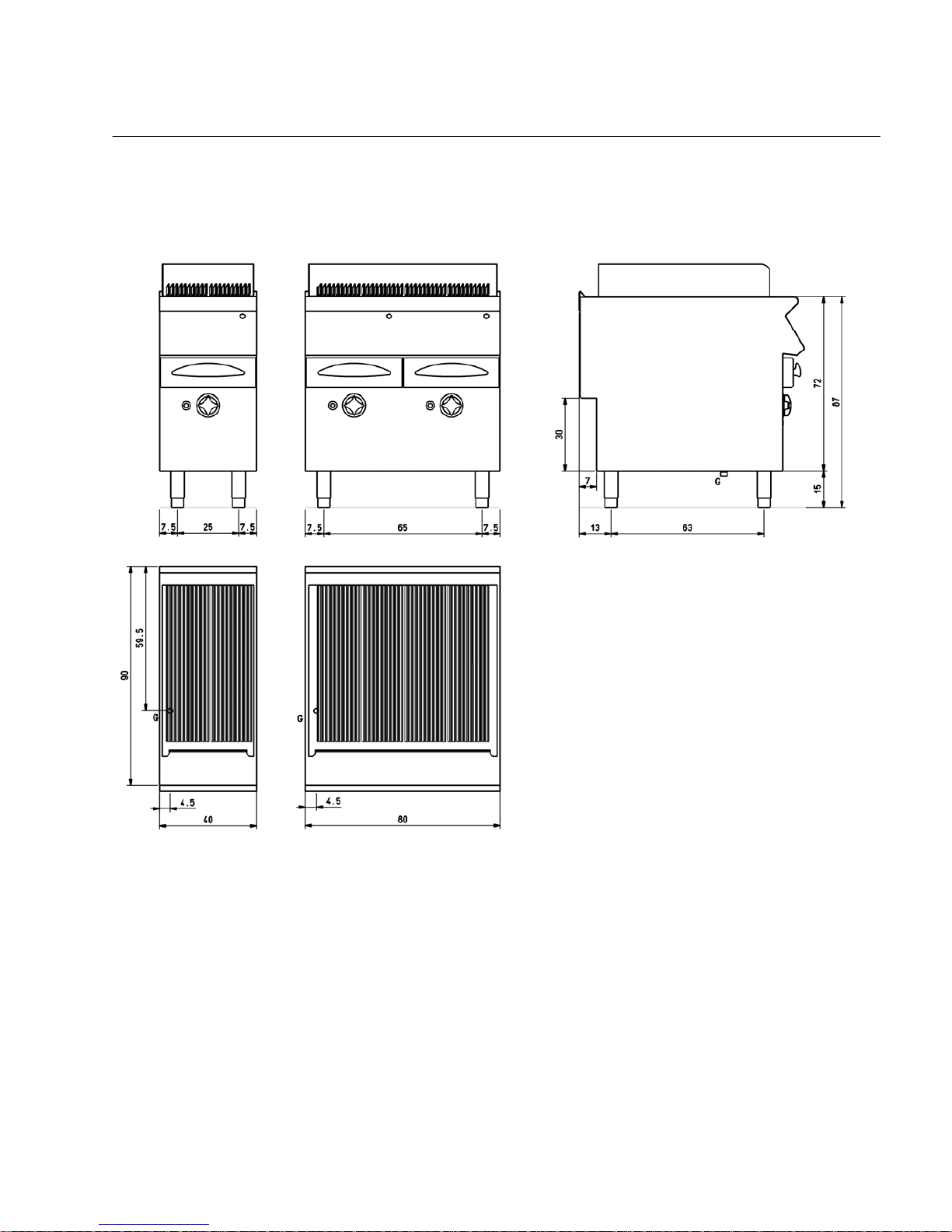
INSTALLATION DIAGRAM
SERIE 90
Mod. ANG9.G
Measurements in cm
Key
G- Attacco arrivo gas - Gasanschluß - Gas connection - Arrivée - Union de gasUNIISO 7/1 R3/4
(CR0687740) 1
Page 3
1
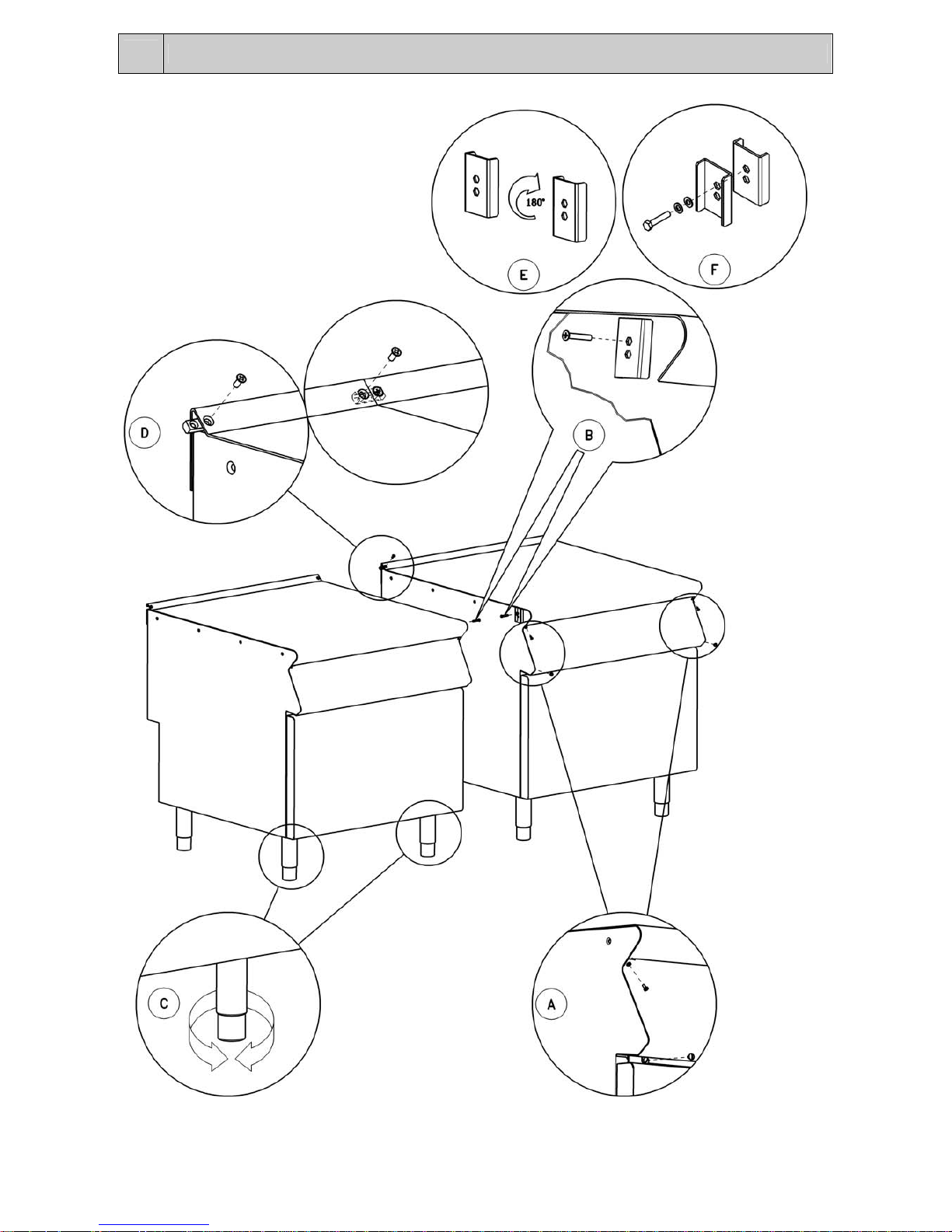
JOINING APPLIANCES TOGHETHER IN LINE
2
Page 4
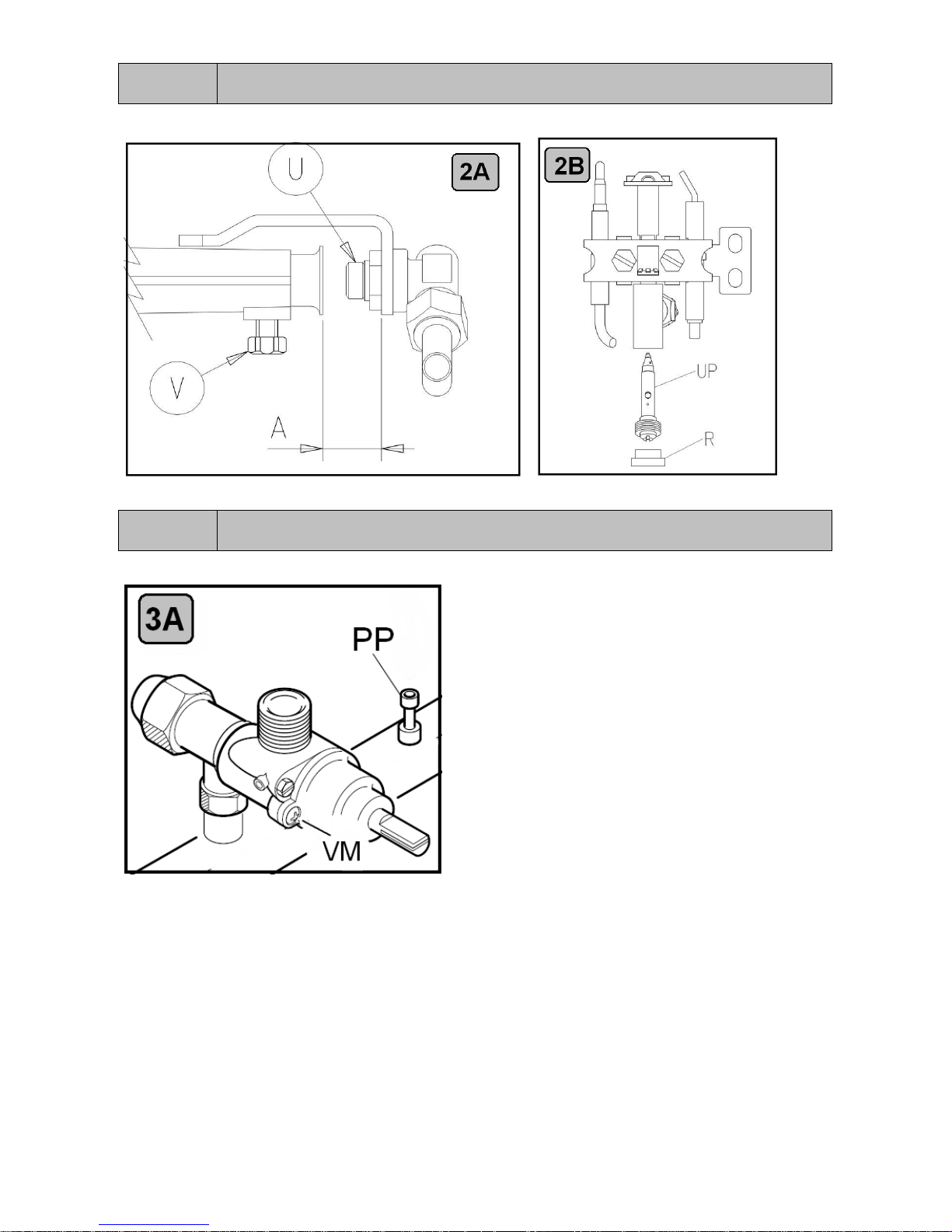
FIG. 2
MAIN BURNER / PILOT BURNER
FIG. 3
GAS VALVE / TAP
3
Page 5
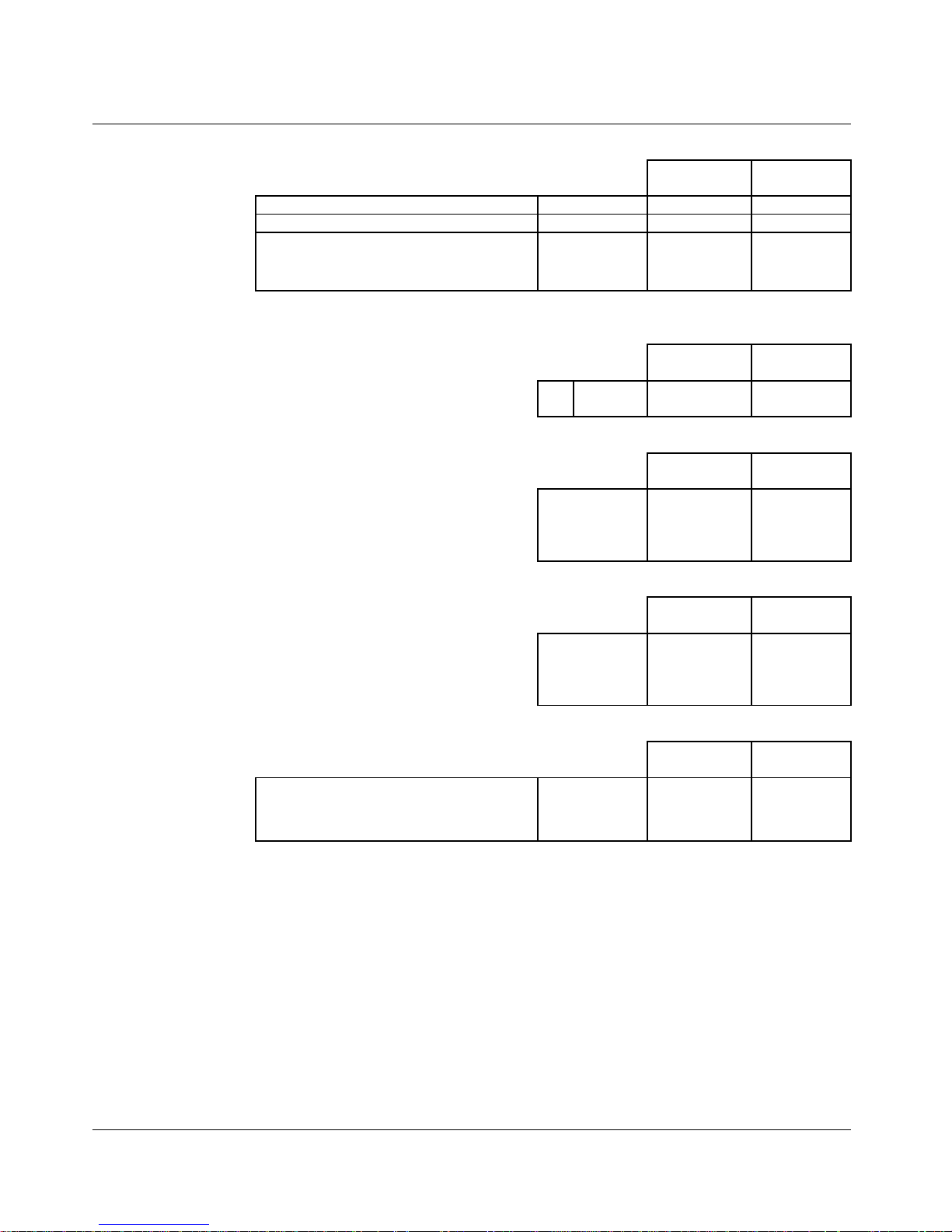
TECHNICAL DAT
A
NATURAL
GAS
PROPANE
MAIN
2.90 1.75
PILOT
45 25
TURN DOWN SCREW
1.80
1
/4 Turn open
From full
y
in
1.05
1
/4 Turn open
From full
y
in
NATURAL
GAS
PROPANE
NATURAL
GAS
PROPANE
NATURAL
GAS
PROPANE
NATURAL
GAS
PROPANE
30
41.00 39.6
T1 - INJIECTOR OREFICES SIZES
MMA
MM
MARKING
T2 - BURNER AERATION SHUTTERS SETTING
(CR0687740) 4
MM
18
MJ/h
1.13 2.75kPa
T3 - NOMINAL GAS CONSUMPTION
T4 - MAXIMUM GAS INLET PRESSURE
1.00 2,50
T5 - NOMINAL TEST POINT PRESSURE VALUES
VALUES SHOWN ARE THOSE
MEASURED AT THE MANIFOLD
PRESSURE TEST POINT.
kPa
Page 6
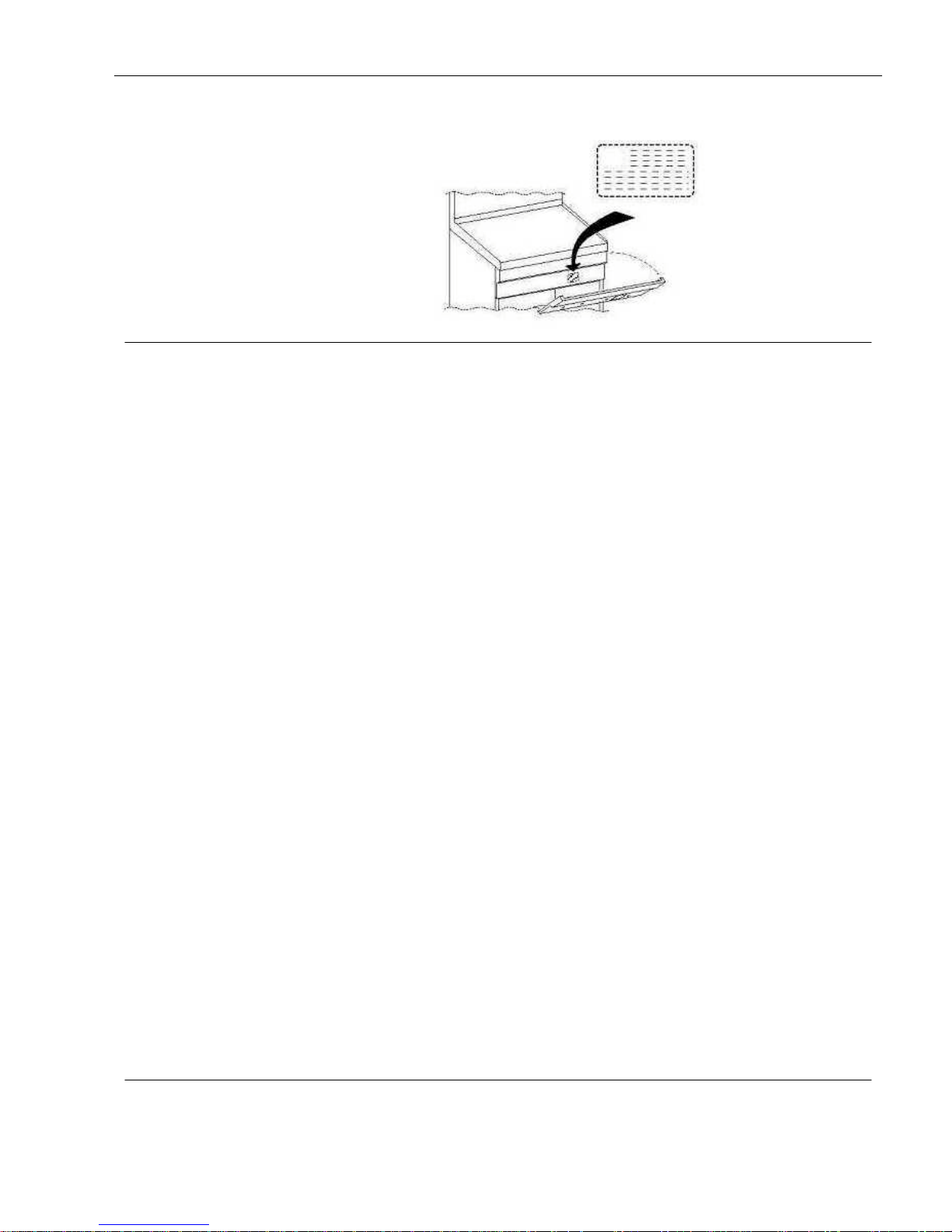
ATTENTION
The data plate is inside the control panel.
CONTENTS . . . . . . . . . . . . . . . . . . . . . . . . . . . . . . . . . . . . . . . . . . . . . . . . . . . . . . . . . . . . . . . . . . . . . . . . . . . . . . . . . . . . . . . . . . . . . . . . . . . . . . . . . . . . . . . . . . . . . . . . . .. . . . . . . . .page
INSTALLATION INSTRUCTIONS
. . . . . . . . . . . . . . . . . . . . . . . . . . . . . . . . . . . . . . . . . . . . . . . . . . . . . . . . . . . . . . . . . . . . . . . . . . . . . . . . . . . . . . . . . . . . . . . . . . . . . . . . . . . .5
INSTALLATION . . . . . . . . . . . . . . . . . . . . . . . . . . . . . . . . . . . . . . . . . . . . . . . . . . . . . . . . . . . . . . . . . . . . . . . . . . . . . . . . . . . . . . . . . . . . . . . . . . . . . . . . . . . . . . . . . . . . . . . . . . . . . . .. . . . . . . . . .5
Positioning
Joining appliances togheter in line
Connecting to the gas supply
CONVERSION TO DIFFERENT TYPE OF GAS . . . . . . . . . . . . . . . . . . . . . . . . . . . . . . . . . . . . . . . . . . . . . . . . . . . . . . . . . . . . . . . . . . . . . . . . . . . . . . . . . . . . . . . . . . . . . . . . . . . . . . . . . . . . . . .5
Replacement of burner injector and adjustment of burner air flow
Adjusting of minimum flow to the burner
Replacement of pilot burner injector
COMMISSIONING PROCEDURE . .. . . . . . . . . . . . . . . . . . . . . . . . . . . . . . . . . . . . . . . . . . . . . . . . . . . . . . . . . . . . . . . . . . . . . . . .. . . . . . . . . . . . . . . . . . . . . . . . . . . . . . . . . . . . . . . . . . . . . . . . .5
Testing the gas system
Testing the nominal thermal power
Setting the manifold gas pressure
TROUBLESHOOTING GUIDE . . . . . . . . . . . . . . . . . . . . . . . . . . . . . . . . . . . . . . . . . . . . . . . . . . . . . . . . . . . . . . . . . . . . . . . . . . . . . . . . . . . . . . . . . . . . . . . . . . . . . . . . . . . . . . . . . . . . . . . . . . . . .5
The pilot burner is difficult or impossible to ignite
The pilot burner goes out during use
The main burner is difficult or impossible to ignite
REPLACEMENT OF SPARE PARTS . . . . . . . . . . . . . . . . . . . . . . . . . . . . . . . . . . . . . . . . . . . . . . . . . . . . . . . . . . . . . . . . . . . . . . . . . . . . . . . . . . . . . . . . . . . . . . . . . . . . . . . . . . . . . . . . . . . . . . .5
Burners, Thermocouples, Ignition electrodes
Gas tap, Piezo igniter
USE AND MAINTENANCE INSTRUCTIONS
. . . . . . . . . . . . . . . . . . . . . . . . . . . . . . . . . . . . . . . . . . . . . . . . . . . . . . . . . . . . . . . . . . . . . . . . . . . . . . . . . . . . . . . . . . . . . . . 6
WARNINGS . . . . . . . . . . . . . . . . . . . . . . . . . . . . . . . . . . . . . . . . . . . . . . . . . . . . . . . . . . . . . . . . . . . . . . . . . . . . . . . . . . . . . . . . . . . . . . . . . . . . . . . . . . . . . . . . . . . . . . . . . . . . . . . . . . . . . . . . . . . 6
USE . . . . . . . . . . . . . . . . . . . . . . . . . . . . . . . . . . . . . . . . . . . . . . . . . . . . . . . . . . . . . . . . . . . . . . . . . . . . . . . . . . . . . . . . . . . . . . . . . . . . . . . . . . . . . . . . . . . . . . . . . . . . . . . . . . . . . . . . . . . . . . . . . 6
Positioning the cast iron grills
Fat drainage drawer
Use of the grill
Turning on the burners
Turning off the burners
CARE AND MAINTENANCE . . . . . . . . . . . . . . . . . . . . . . . . . . . . . . . . . . . . . . . . . . . . . . . . . . . . . . . . . . . . . . . . . . . . . . . . . . . . . . . . . . . . . . . . . . . . . . . . . . . . . . . . . . . . . . . . . . . . . . . . . . . . . . 6
SPARE PARTS LIST . . . . . . . . . . . . . . . . . . . . . . . . . . . . . . . . . . . . . . . . . . . . . . . . . . . . . . . . . . . . . . . . . . . . . . . . . . . . . . . . . . . . . . . . . . . . . . . . . . . . . . . . . . . . . . . . . . . . . . . . . . . . . . . . . . . . 6
(CR0687740) 5
Page 7

(CR0687740) 6
INSTALLATION INSTRUCTIONS
CONFORMITY TO REGULATIONS AND LAWS
The appliance is to be installed by an authorised person in
accordance with AS5601 - the installer must ensure the
installation complies with all regulatory and manufacturer
requirements and operationally and functionally test, make
necessary adjustments and commission the appliance as part
of installation.
WARNING
The manufacture declines any responsibility if these
obligations are not respected.
INSTALLATION
The overall dimensions, position/dimensions of connections
and technical data are given in the installation diagram.
If the appliance cannot be adjusted to perform correctly call
the tecnichal assistant service.
Positioning
• Install the appliance in a suitably ventilated environment.
• Position the appliance at least 15 cm from surrounding
walls. This distance may be reduced if the walls are
flameproof or protected by insulating material.
• This appliance is not designed for built-in installation.
• Remove the protective film from the external panels.
Use a suitable solvent to remove any glue residue.
• In stand-alone installations, appliances 40 or 60 cm wide
must be fixed to the floor using the flanged feet.
• Level the appliance by means of the adjustable feet.
• In case of installation on a level bench top, it must be used
the approriate feets equipped with the applince (height = 30
mm).
Joining appliances together in line ( Fig. 1 )
• Remove the control panels ( Fig. 1A ).
• Remove the fixing screw nearest the control panels, from
each side to be joined ( Fig. 1B ).
• Place the appliances next to each other and level them until
the tops match ( Fig. 1C ).
• Insert the coupling plate ( supplied ) into the side housings
on the backs. Join together the appliances screwing M5
flathead screws ( supplied ) in to coupling plate ( Fig. 1D ).
• Turn 180º one of the two plates inside the appliances to be
joined together ( Fig. 1E ).
• Join together the appliances , at the front side, screwing the
M5x40 screw ( supplied ) on the opposite insert (Fig. 1F ).
Connecting to the gas supply
• Install a shut-off valve upstream of the appliance, in a
place easily accessible.
• Check if the appliance is adjusted for the type of gas with
which it will be supplied. If not, convert it according to the
instructions in the paragraph "Conversion to different type of
gas".
• Do not use supply pipe having a diameter smaller than the
appliance’s gas connection.
• Check that there are no leaks at the connection points.
CONVERSION TO A DIFFERENT TYPE OF GAS
To convert the appliance to a different gas supply, follow the
instructions below.
Use the injectors contained in the bag supplied with the
appliance.
Replacement of burner injector and adjustment of
burner air flow (Fig. 2)
• Remove the upper front panel and drawer.
• Unscrew the existing injector "U" and replace it with the
one indicated in Table T1 in Technical Data section.
• Position the air regulator at the distance “A” indicated in
Table T2 in Technical Data section.
• Retighten screw V and seal it with red paint.
Adjustment of minimum flow to the burner (Fig. 3)
• Remove the upper front panel.
• Unscrew the existing screw "VM" and replace it with the
one indicated in Table T1 in Technical Data section.
Replacement of pilot burner injector (Fig. 2)
• Remove the upper front panel.
• Unscrew fitting R and replace injector UP with the one
indicated in Table T1 in Technical Data section.
• Retighten fitting R.
COMMISSIONING PROCEDURE
Testing the gas system
• Switch on the appliance following the instructions for use.
Test burners ignition and flame uniformity. Also check the
appliance for gas leaks and make sure the gas exhaust system
functions correctly.
• If necessary, consult the “Troubleshooting guide” below.
Testing the gas nominal thermal power
• After installation, conversion to a different type of gas or
servicing, check the nominal thermal power of the appliance.
• The appliance functions at the nominal thermal power when
is fitted with the appropriate injectors for the gas used and
the gas pressure measured at the manifold pressure test point
is commissioned to the appropriate nominal value as
specified in Table T5 in Technical Data section.
Setting the manifold gas pressure (Fig. 3)
• Remove the lower front panel.
• Remove sealed bolt PP from the test point pressure and
connect the pressure gauge pipe.
• Switch on the appliance following the instructions for use
and commission the test point pressure value to the
appropriate nominal values as specified in Table T5 in
Technical Data section.
TROUBLESHOOTING GUIDE
The pilot burner is difficult or impossible to ignite
• Gas supply pressure low.
• Gas pipe or injector clogged.
• Gas tap faulty.
• Piezo igniter faulty.
• Ignition electrode (ignition spark gas should be 3 + 1/0 mm)
or cable faulty.
The pilot burner goes out during use
• Thermocouple faulty, insufficiently heated or incorrectly
connected to gas valve.
• Gas tap faulty.
The main burner is difficult or impossible to ignite
• Gas supply pressure low.
• Injectors clogged.
• Gas tap faulty.
REPLACEMENT OF SPARE PARTS
Before every intervention close the gas and water shut-off
valves upstream the appliance and disconnect the
electrical supply.
Never tamper with any of the sealed components.
After every intervention, check for gas leaks, if necessary.
Page 8

(CR0687740) 7
Burners, Thermocouples, Ignition electrodes
• Remove the lower and upper front panel, drawer, cast iron
grills, splashguard , burner tiles, and replace the component.
Gas tap, Piezo igniter
• Remove the lower and upper front panel and replace the
component.
USE AND MAINTENANCE INSTRUCTIONS
WARNINGS
Do not store flammable materials in or near the appliance. Do
not spray aerosols in the vicinity of this appliance while it is
in operation.
Beware of the appliance’s hot surfaces!
This appliance is designed for professional use and must only
be used by trained personnel. It is exclusively designed to
cook food. Any other use is considered improper.
If the appliance breaks down, close the gas shut-off valve
upstream of the appliance and call the technical assistance
service.
Repairs should only be carried out by authorised service
centres.
For service and spares parts, please contact Comcater 1800
810 161.
The manufacture declines any responsibility if these
obligations are not respected.
Read this manual carefully and keep in a safe place.
Before using the appliance, thoroughly clean all surfaces that
may come into contact with food.
USE
Positioning the cast iron grills
The cooking grill can be positioned in two ways depending
on the type of cooking and characteristics of food to be
cooked.
- horizontal position : suitable for slow cooking
- inclined position : suitable for normal cooking
Fat drainage drawers
• Fat that falls from the cast iron grill during cooking passes
through the tiles to be collected in a special drawers. While
using the appliance , empty them when they are nearly full.
• For better cooking results and to facilitate cleaning at the
end of the day, pour 2-3 cm of water into each grease
collection drawer.
Use of the grill
The gas tap control knob has the following positions:
Ɣ Off
Pilot ignition
maximum cooking temperature
minimum cooking temperature
Turning on the burners
• Press the knob in and turn to the position “ Pilot ignition “.
• Press the knob fully in and press the piezo igniter button to
light the pilot flame. Hold the knob pressed in for approx. 20
seconds, then release it. If the pilot flame goes out, repeat the
operation
Make sure the pilot burner is lit by checking the flame
through the inspection hole in upper front panel.
• Turn the knob to the desired cooking temperature.
Turning off the burners
• To switch off the main burner, turn knob to position “ Pilot
ignition “.
• To switch off the pilot burner, turn knob to position “Off”.
CARE AND MAINTENANCE
• Do not wash the appliance with jets of water.
• Before cleaning the appliance, disconnect from the electric
power supply (if connected).
• Clean stainless steel surfaces daily using water and nonabrasive detergents. Rinse thoroughly and dry.
• Do not use steel wool pads or chlorine-based products.
• Do not use corrosive substances to clean the floor
underneath the appliance.
• If the appliance is to remain idle for a long period, close the
gas shut-off cock upstream of the appliance and clean
thoroughly.
• The appliance should be inspected and the gas exhaust pipe
cleaned by an authorised service engineer at least twice a
year.
For this purpose we recommend taking out a service contract.
SPARE PARTS LIST
• Main burner
• Pilot burner
• Thermocouple
• Ignition electrode
• Gas tap
• Piezo igniter
• Tiles
 Loading...