

Page 1
INSTALLATION, OPERATION
AND SERVICE MANUAL
GF SERIES OF GAS FRYER
7455.0975
WARNINGS
IMPROPER INSTALLATION, ADJUSTMENT,
ALTERATION, SERVICE OR MAINTENANCE CAN CAUSE
INJURY OR DEATH. THE INSTRUCTION MANUAL MUST
BE READ CAREFULLY BEFORE INSTALLING,
OPERATING OR SERVICING THIS EQUIPMENT
TO BE INSTALLED ONLY BY AN AUTHORISED PERSON
IN ACCORDANCE WITH LOCAL AUTHORITY, GAS,
ELECTRICITY, ANY APPLICABLE STATUTORY
REGULATIONS AND MANUFACTURER REQUIREMENTS.
THIS EQUIPMENT IS DESIGNED FOR COMMERCIAL
CATERING PURPOSES AND WILL GENERATE
SIGNIFICANT HEAT. IT SHALL BE USED BY A
QUALIFIED PEOPLE. HOT SURFACES WILL CAUSE
BURNS. A HAZARD AND RISK ASSESSMENT MUST BE
UNDERTAKEN BY OWNERS AND ALL OPERATORS
MADE AWARE OF THESE.
Gas fryer Manual Page 1
Page 2
DO NOT STORE OR USE FLAMMABLE LIQUIDS NEAR
THIS APPLIANCE. THE PARTS WHICH HAVE BEEN
PROTECTED BY THE MANUFACTURER OR HIS AGENT
SHALL NOT BE ADJUSTED BY THE USER.
DO NOT SPRAY AEROSOLS NEAR THIS APPLIANCE
WHILE IT IS IN OPERATION.
INSTALLATION CLEARANCES AS SPECIFIED MUST BE
OBSERVED.
IF YOU SMELL GAS, TURN THE UNIT OFF AND THE
MAIN GAS SUPPLY VALVE TO THE UNIT. CONTACT
YOUR GAS SUPPLIER OR AN AUTHORISED PERSON.
BEFORE TURNING ON THE MAIN GAS SUPPLY, CHECK
THE UNIT TO BE CERTAIN THAT ALL THE VALVES ARE
IN THE “OFF” POSITION.
PLEASE KEEP THIS MANUAL FOR FUTURE
REFERENCE AND REFERENCE BY ALL OPERATORS.
Gas fryer Manual Page 2
Page 3

TABLE OF CONTENTS
INTRODUCTION...............................................................................................4
GENERAL.......................................................................................................4
WARRANTY...................................................................................................4
GENERAL INFORMATION................................................................................5
INSPECTION..................................................................................................5
OPERATOR MANUAL....................................................................................5
INSTALLATION...............................................................................................5
GAS CONNECTION.......................................................................................5
GAS PRESSURE...........................................................................................5
COMMISSIONING..........................................................................................6
SPECIFICATIONS.............................................................................................6
INSTALLATION...............................................................................................6
Appliance specification...................................................................................8
TEST POINT PRESSURE..............................................................................8
VENTILATION AND AIR SUPPLY..................................................................8
DIMENSIONS.................................................................................................9
ACCESSORIES..............................................................................................9
OPERATING INSTRUCTIONS........................................................................10
LIGHTING INSTRUCTIONS.........................................................................10
IGNITION PROCEDURE..............................................................................11
OPERATOR MAINTENANCE..........................................................................14
CLEANING STAINLESS STEEL..................................................................14
SERVICE.........................................................................................................15
RECOMMENDED SERVICE........................................................................15
BURNER ADJUSTMENTS...........................................................................16
SPARE PARTS.............................................................................................17
TROUBLESHOOTING.....................................................................................18
Exploded view of GF4...................................................................................19
Exploded view of GF3...................................................................................21
Gas fryer Manual Page 3
Page 4

INTRODUCTION
GENERAL
The gas fuelled fryer is designed for commercial catering purposes and
incorporates a wide range of features to benefit the customer.
WARRANTY
This product’s warranty is subject to the terms of local distributor in your own
country and is subject to the correct installation, operation, maintenance and
care of the equipment.
Warranty does not extend to:
•
Damages caused in shipment
•
Damage as a result of incorrect installation.
•
Damage as a result of incorrect operation
•
Damages caused by unauthorised service and use of non original parts
•
Gas supply issues to the equipment
•
Failure resulting from improper maintenance.
•
Failure as a result of tampering with, removal of, or changing any
preset control or safety device
For all warranty work, authorized service and genuine and authorized
spare parts, please contact your local dealer
Please ensure you quote the Model and Serial Number of the unit. The
Model and Serial Number of the unit on the data plate. Please provide this
information for after sales service
Gas fryer Manual Page 4
Page 5

GENERAL INFORMATION
INSPECTION
Please inspect the unit on receipt. If the unit is damaged, contact the carrier
immediately and file a damage claim with them. Save all packing materials
when filing a claim. Freight damage claims are the responsibility of the
purchaser and are not covered under warranty.
OPERATOR MANUAL
This manual contains important information for your safety and the
installation, operation, maintenance and service of this equipment.
Please read the manual carefully and ensure all operators of the
equipment are aware of the contents and safety requirements.
Warning: You must assess all hazards and risks associated with the
operation of the equipment in your environment and advise all operators
of these.
INSTALLATION
This equipment must be installed by an authorized person in
accordance with local authority, gas, electricity, any applicable statutory
regulations and manufacturer requirements.
GAS CONNECTION
The appliance must be connected by an authorized person to the gas type
specified on the unit. The gas type is shown adjacent to the gas connection
point on the rear panel and on the data plate. Connect to and use only the
correct type of gas.
GAS PRESSURE
The authorized person installing this equipment must ensure that the gas
operating pressure is the same as shown on the data plate and that there is
sufficient gas volume.
Gas fryer Manual Page 5
Page 6
COMMISSIONING
The authorized person installing this equipment must commission the
equipment in accordance with local gas safety regulations - gas leakage,
operational checking, adjustments and instructing the owner on use of the
equipment are prescribed requirements.
SPECIFICATIONS
INSTALLATION
THIS EQUIPMENT MUST BE INSTALLED BY AN AUTHORIZED
PERSON IN ACCORDANCE WITH LOCAL AUTHORITY, GAS,
ELECTRICITY, ANY APPLICABLE STATUTORY
REGULATIONS AND MANUFACTURER REQUIREMENTS.
NOTE: INSTALLATION IS THE RESPONSIBILITY OF THE OWNER
Gas Inlet Connection: 1/2” BSP Female.
Gas Connection Point: The gas connection point is located at the rear of
the unit
Details are shown in the drawings at the rear of
this manual.
Gas Connection: The appliance must be connected by an
authorized person to the gas type specified on the
unit. The gas type is shown adjacent to the gas
connection point on the rear panel and on the data
plate. Connect to and use only the correct type
of gas.
The authorized person installing this equipment
must comply with local gas safety standard.
Prescribed requirements include, commission the
equipment, gas leakage testing, operational
checking and adjustments.
All units are tested and adjusted at the factory; however, all burners and pilots
must be checked at the installed location and adjusted as necessary.
Gas fryer Manual Page 6
Page 7

Data Plate: The data plate is located at the rear of the fryer
Installation Clearances: The MINIMUM clearance from combustible
surfaces is;
Sides 150 mm, and
Rear 50mm
Adequate clearance must also be provided for
service.
Levelling: To adjust the legs to level the unit to the floor
and/or to slightly adjust the height of the unit, raise
the front of the unit and adjust the legs (ensure
safe work practices). Similarly, raise the back of
the unit and adjust the legs. DO NOT LAY THE
UNIT ON ITS BACK. ENSURE THE UNIT IS
LEVEL.
Gas fryer Manual Page 7
Page 8

Appliance specification
Product name
Gas Fryer
Type of appliances
Type A1
Gas Category
I
2H
I
2E
I
2L
I
2E+
Gas and Supply
Pressure
G20 at 20 mbar G20 at 20
mbar
G25 at
25 mbar
G20/G25 at
20/25 mbar
Country of
Destination
AT, BG, CR, CZ, DK,
EE, FI, GR, HR, HU, IS,
IE, IT, LV, LT, NO, PT,
RO, SK, SI, ES, SE, CH,
TR and GB
BE, FR NL DE, LU, PL
Injector Size Ø 2.3 mm Ø 2.3 mm Ø 2.2 mm Ø 2.2 mm
Gas Consumption 34kW for GF4 ; 27KW for GF3
Warning: This appliance shall be installed in conformity with the current regulations and used
only in a well-ventilated location. Consult the instructions before installing and using
this appliance.
Burner rating of ignition pilot: 750W
Nominal Gas Consumption Table for
I
2H
only ( reference only)
BURNER Test pressure at gas inlet Test pressure at test point
GF4 20 mbar 13.5 mbar
GF3 20 mbar 14.7 mbar
Note: The pressure test point is located on the gas manifold (refer below).
TEST POINT PRESSURE
The pressure test point is located on the gas manifold and is accessed by
opening the door. The test point pressure is shown in the ‘Nominal Gas
Consumption Table’ above and is set with the burners operating at maximum
setting.
VENTILATION AND AIR SUPPLY
All gas burners and pilots require sufficient air to operate. For optimum
performance and for your safety, it is ESSENTIAL that the equipment, in the
installed position, has the proper air and ventilation and the correct
exhaust/canopy and air balance. The correct installation and compliance with
all regulatory and other requirements is the responsibility of the
purchaser/owner.
Please note that a strong exhaust canopy will create a vacuum if there is
insufficient replacement air. The amount of air exhausted must be replaced by
an equal amount of air.
Gas fryer Manual Page 8
Page 9

Airflow to the appliance must not be blocked or restricted (e.g. large objects
should not be placed in front of the appliance). The flue must never be
covered or restricted in any way.
DIMENSIONS
* Please note that the outside dimensions of GF3 and GF4 are identical.
* Product dimensions are 393 x 750x 1160 mm
* Packing dimensions are 510 x 820 x 1230 mm
ACCESSORIES
1. Fry baskets @ 2
2. Rack @ 1
3. Oil extension pipe @ 1
4. Clog clearance prod @ 1
5. Operating manual @ 1
Gas fryer Manual Page 9
Page 10
OPERATING INSTRUCTIONS
LIGHTING INSTRUCTIONS
DO NOT OPERATE THE UNIT UNLESS IT HAS BEEN
INSTALLED AND COMMISSIONED BY AN AUTHORIZED
PERSON.
BEFORE TURNING ON THE MAIN GAS SUPPLY, CHECK AND
ENSURE THAT ALL THE VALVES ARE IN THE “OFF”
POSITION.
THIS EQUIPMENT IS DESIGNED FOR COMMERCIAL
CATERING PURPOSES AND WILL GENERATE SIGNIFICANT
HEAT. HOT SURFACES WILL CAUSE BURNS. A HAZARD AND
RISK ASSESSMENT MUST BE UNDERTAKEN BY OWNERS
AND ALL OPERATORS MADE AWARE OF THESE.
NOTE: Ensure the gas supply to the equipment is turned ON.
NOTE: For your safety, the valve comes with a flame failure sensing device. If
the device does not sense a flame, gas supply to the burner will be
cut.
Gas fryer Manual Page 10
Page 11
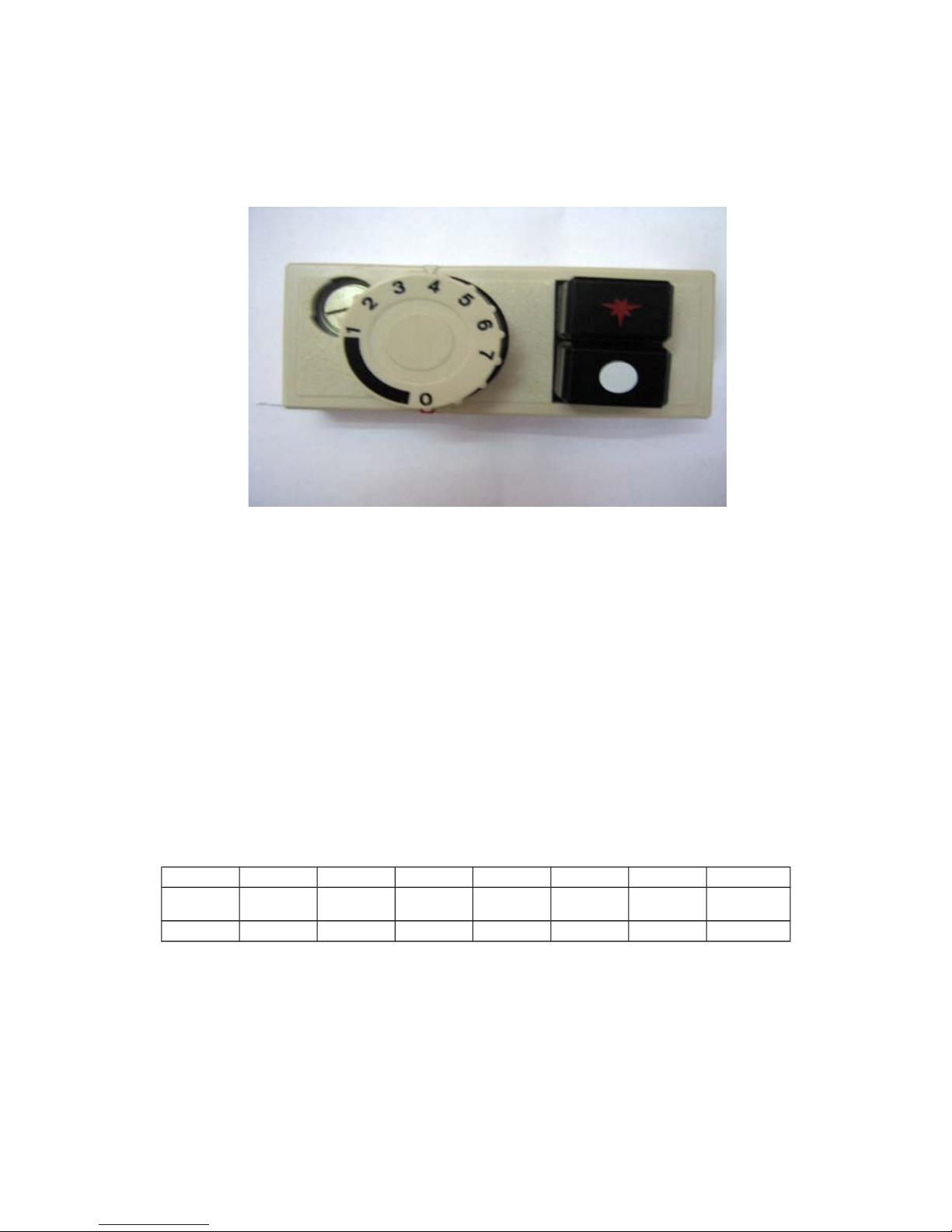
IGNITION PROCEDURE
NOTE: Ensure the gas supply to the equipment is turned ON
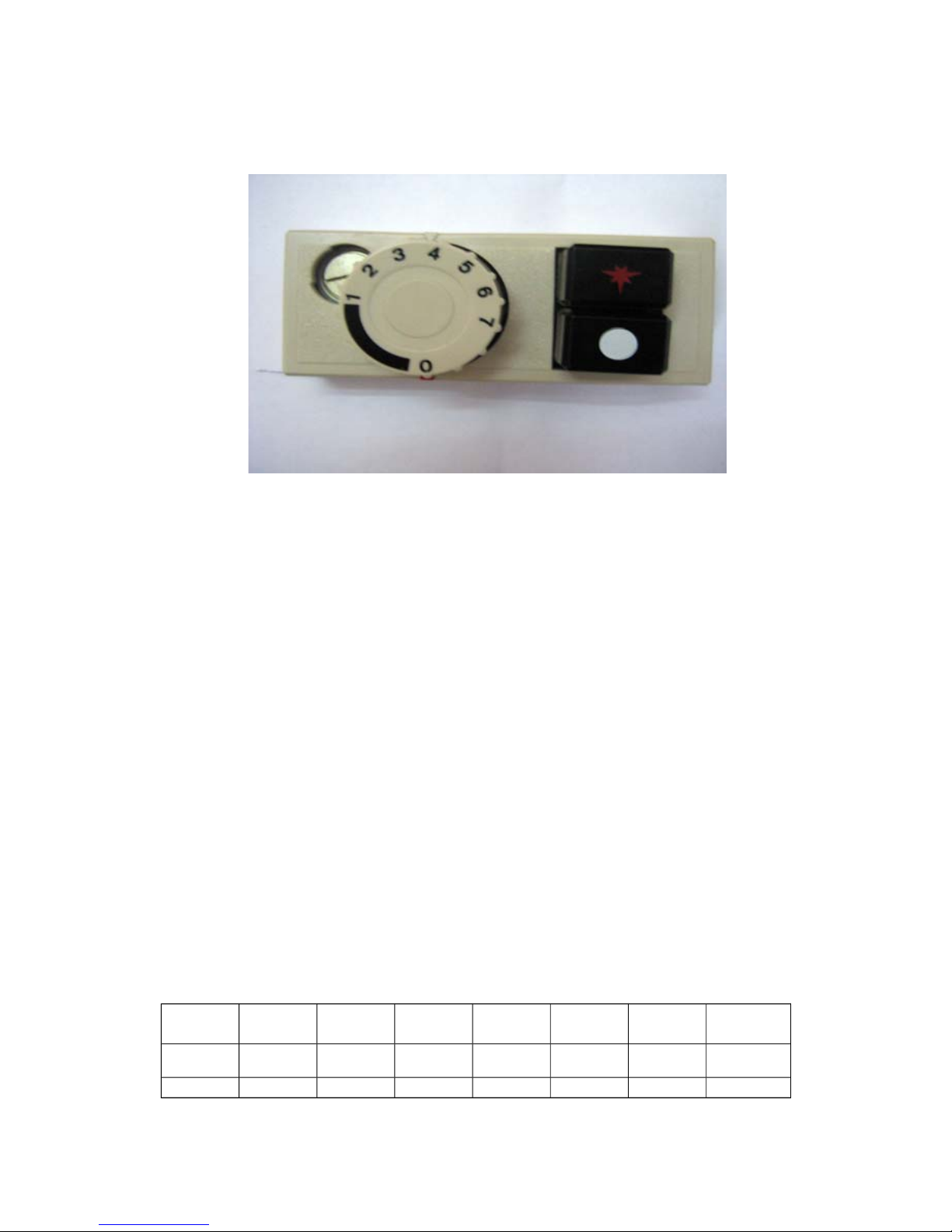
1) Starting from the “0” position
2) Press the PILOT ★ position.
3) Manually light the pilot by use of a spark gun or lighter.
4) Continually press the ★ button for 15 seconds. Now when the ★ button is
released, the pilot flame should stay alight. If it does not, go back to step
(1) and start all over again. When the automatic valve senses that the
pilot is alight, the gas flow to the main burner is opened.
5) If the pilot flame cannot be lit after repeated attempts, check out the
troubleshooting page of this manual.
6) Turn the knob to setting “1”.
7) Turn the knob to the setting of your desirable temperature. Please refer to
the following table.
Setting 1 2 3 4 5 6 7
o
C 120 135 145 160 175 185 195
o
F 248 275 293 320 347 365 383
When the oil temperature reaches the desirable temperature (normally at this
point of time, the main burner will be temporarily closed), the fryer can be
loaded.
Warning:
Operator must follow the procedure in operating this fryer
Gas fryer Manual Page 11
Page 12

Take particular care when loading the food into the fryer to avoid being
scalded by splashing oil.
Hang the fry basket on the hangar until oil is dripped out.
Do not overload the fryer basket.
Pilot Standby Position
To turn the main burner off and keep the pilot ON, rotate the knob to “0”
position.
Shut Down/Pilot OFF
- Turn the control knob to “0” position
- Depress the ● knob. Gas supply to both the main burner as well as the
pilot burner will be cut off simultaneously.
NOTE: If the pilot flame were accidentally extinguished, the flame failure
safety device would operate and cut the gas flow to the main burner. It would
then be necessary to re light the pilot by following the above procedure.
- Wait for about 15 seconds for the valve to reset.
- Repeat from step (1) of the IGNITION PROCEDURE
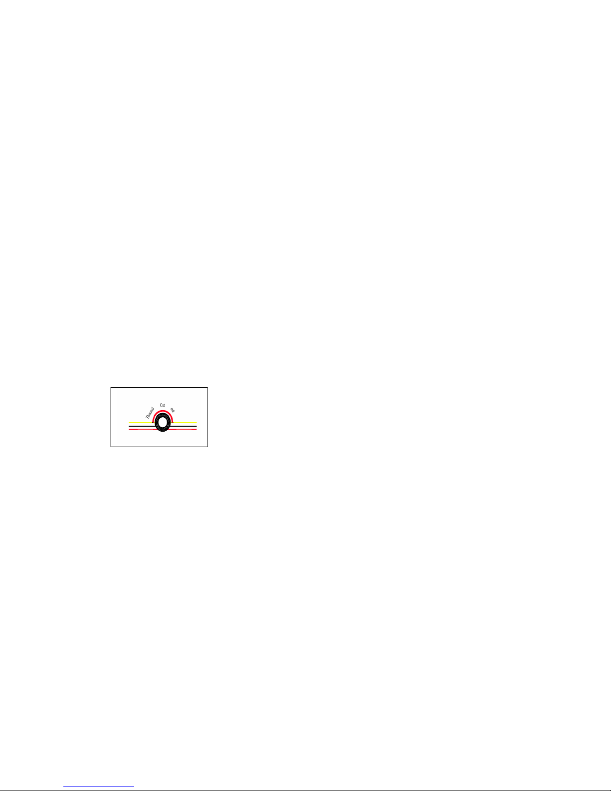
Thermal cut out tripping:
Gas fryer Manual Page 12
Page 13

Adding Oil
Caution: Add oil to frypot between the maximum and minimum level.
Caution: Do not use solid oil or solid shortening. Only liquid oil should be
used in this fryer
Oil filtering procedure:
1) Turn off the fryer and let it coot down for about 20 minutes
2) Screw in the Oil drain extension pipe (hung on the inside of the door) to
the drain valve outlet
3) Make sure that the nozzle end of the oil drain extension pipe faces a oil
collector (or an oil filtering cart)
Pull the safety latch of the lever and start turning the lever anticlockwise
slowly. CAUTION: DO NOT TURN THE LEVER TOO FAST. THIS COULD
RESULT IN HOT OIL SPLASHING OUT FROM THE DRAIN NOZZLE
Oil filtering
Oil should be filtered regularly in order to lengthen its usable life span. This
will also reduce the operating cost. The following factors all contribute to the
shortening of oil life.
← Contact with air
← Carbonated food crumbs and particles.
← Contact with any surface other than stainless steel.
← Contact with seasoning, spices and salt.
Cooking food under a temperature too high
Gas fryer Manual Page 13
Page 14
OPERATOR MAINTENANCE
USE ONLY SUITABLE CHEMICALS AND OBSERVE ALL
MANUFACTURER SAFETY REQUIREMENTS FOR SAFE
HANDLING AND USE.
Warning: Ensure the appliance is off and the parts are cool to touch.
1)
Avoid splashing water onto any parts and piping.
2)
Check the piping connections and gas circuitry regularly.
3)
Avoid clogging of the flue gas ventilation. Any obstacles in the flue can
cause incomplete combustion.
4)
Make sure the gas type and pressure conforms to the specification as
shown in the data plate
Cleaning must be regular and thorough to ensure safe and efficient operation
of the equipment and to prevent flare-up. The amount of usage and the type
of products being cooked will largely determine how often complete cleaning
is necessary - you must assess this.
To clean the items, use a suitable detergent and warm water and scrubbing
brush. Repeated scrubbing will be necessary if deposits are heavy and baked
on.
CLEANING STAINLESS STEEL
Regularly wipe the surface with hot water and detergent. Rinse the washed
area with a wet sponge and clean water and wipe the area dry to prevent
streaking. Follow this process and wash a small area at a time to prevent
chemical residue and streaking.
Stainless steel may discolour if overheated. These stains can usually be
removed using an appropriate powder/paste. To scrape off heavy deposits of
grease and oil, use only wood or plastic tools as necessary.
Note: Never use steel wool to clean stainless steel.
Note: Damage may occur if chemicals not suitable for stainless steel are
used.
Gas fryer Manual Page 14
Page 15
SERVICE
FOR YOUR SAFETY, ALL SERVICE WORK MUST BE
CARRIED OUT BY AN AUTHORISED PERSON AND USE
ONLY ORIGINAL SUPPLIED AND SPECIFIED PARTS.
TEST ALL FITTINGS, PIPES AND PIPE CONNECTIONS FOR
LEAKS IN ACCORDANCE WITH APPROVED GAS LEAK TEST
PROCESSES AND METHODS. DO NOT USE A FLAME.
RECOMMENDED SERVICE
It is recommended that your appliance be serviced by an authorized person
every 12 months. This period is for guidance purpose only and may vary
based on usage of the equipment and operator care. Prescribed service tasks
include;
•
Functional test of all components and clean and adjust as necessary.
•
Inspect and clean all gas valves and lubricate with an industry
approved lubricant.
•
Inspect all gas piping.
•
Check and adjust specified gas pressures.
•
Leak test.
•
Full operational, performance and safety test.
Gas fryer Manual Page 15
Page 16

BURNER ADJUSTMENTS
Leak Test
1)
Ensure that all control valves are in the OFF position.
2)
Turn on the main gas supply valve.
3)
Light all pilots.
4)
Leak test all valves and fittings using approved methods.
5)
Correct any leaks as required and re-check.
6)
Shut off all valves and set the control knobs to “OFF” position.
Test Point Pressure
The pressure test point is located on the gas manifold. The gas manifold and
pressure test point is accessed by opening the fryer door. The test point
pressure is shown in the ‘Nominal Gas Consumption Table’ and is set with the
burners operating at maximum setting.
Pilot Burner Adjustment
Set all pilots so that the flame envelops the tip of the thermocouple by
adjusting the pilot flame adjusting screw on the gas valve - clockwise to
decrease, or anti-clockwise to increase.
Service adjustment should not be necessary unless changing the gas valve or
performing a gas conversion.
Burner Adjustment
The burner orifices are fixed as specified and cannot be adjusted. The
specified gas rate will be achieved if the gas supply pressure and test point
pressure is correct.
A distinct blue flame over the entire port area of the burner will be achieved at
full rate when the air supply is correct and the injector and burner are properly
aligned.
If the flame is yellow and wavy, the cause needs to be established.
WARNING: If you are not competent in performing any service task or require
assistance, please contact your local service agent.
Gas fryer Manual Page 16
Page 17

SPARE PARTS
A list of major spare part items is shown at the end of this manual.
These parts and all other parts used in the fryer are available from your local
dealer.
Warning: Use only genuine spare parts.
Warning: Use of non authorized parts voids warranty and equipment
approval.
Gas fryer Manual Page 17
Page 18
TROUBLE SHOOTING
ALL SERVICE WORK TO BE COMPLETED BY AN
AUTHORISED PERSON.
BURNERS
CONDITION CHECK
Pilot will not light. Gas supply is on and gas pressure is correct
Blocked pilots
Pilot adjusting screw
Pilot repeatedly goes out. Pilot flame size and position
Thermocouple
Flame safety device
Yellow Burner Flame. Primary air
Flame lifting off burner ports. Primary air
‘Popping’ after turning off. Primary air
Burner flame too large. Gas pressure
Delayed ignition. Pilot flame
Burner and ports clean
Gas pressure
Flame burns back to orifice Primary air
Gas fryer Manual Page 18
Page 19
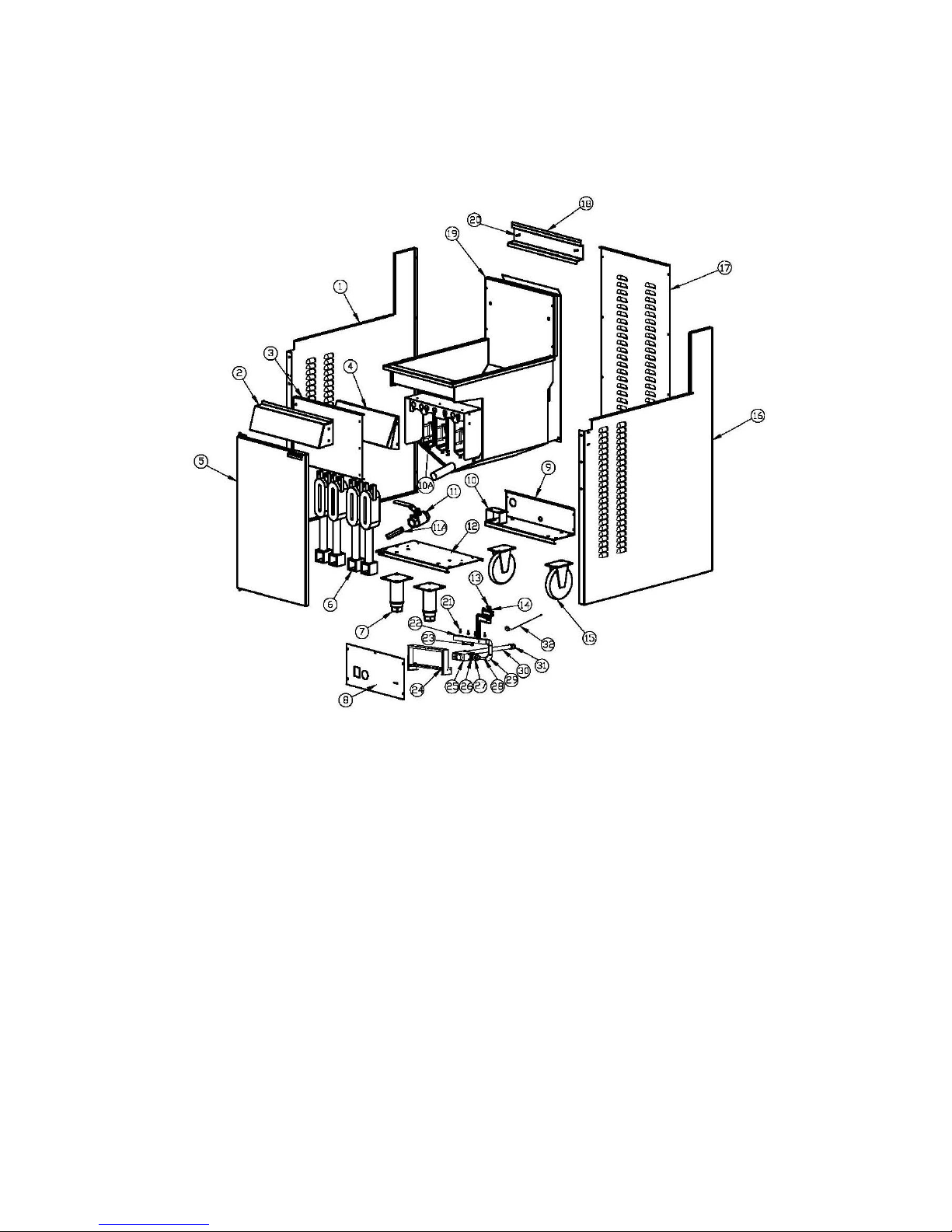
Exploded view of GF4
Gas fryer Manual Page 19
Page 20

Bill of Material (GF4)
Item Description P/N Drawing # Qty
1 Left panel 10113062 1
2 Front panel S15015 B-GF-GY02 1
3 Shield 10113055 1
4 Front baffle 10113044 1
5 Door S01097 B-GF-MZJ-01 1
6 Burner B06181 B-GF-JS-01-11 4
7 Feet S99002 2
8 Control panel 10113060 1
9 Rear bottom 10113054 1
10 Gas pipe bracket 10113039 1
10A Internal Baffle B-JS-GF-01 4
11 Drain valve B09022 1
11A Drain pipe S15029 1
12 Front bottom 10113007 1
13 Pilot B06362 1
14 Thermocouple SIT-0.200.015 1
15 Caster B05080 2
16 Right panel 10113053 1
17 Back 10113014 1
18 Basket hangar 10113029 1
19 Frypot Ass'y S15013 B-GF4-GYGF4 1
20 Screw S15012 2
21 Injector S15002 4
22 Manifold Ass'y B-GF4C-LJ03 1
23 Pressure test point B06383 1
24 Manifold support 10113059 1
25 Gas valve B06330 1
26 Reducer B11089 1
27 Coupler B14017 2
28 Gas pipe B-GF4C-LJ01 1
29 Elbow B12008 2
30 Gas inlet pipe B-GF4-LJ01 1
31 Reducer B11014 1
32 Hi limit E03040
1
Gas fryer Manual Page 20
Page 21
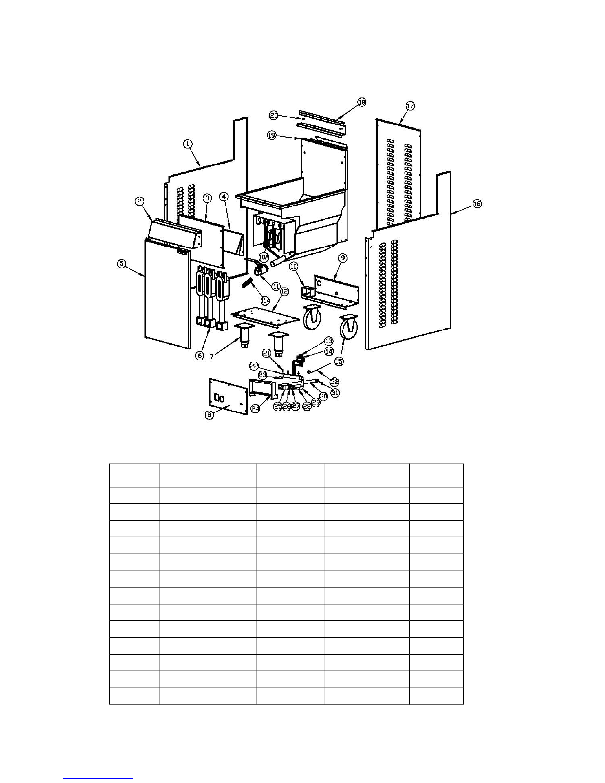
Exploded view of GF3 (7455.0975)
Bill of Material GF3 (7455.0975)
Item Description P/N Drawing # Qty
1 Left panel 10113062 1
2 Front panel S15015 B-GF-GY02 1
3 Shield 10113055 1
4 Front baffle 10115013 1
5 Door S01097 B-GF-MZJ-01 1
6 Burner B06181 B-GF-JS-01-11 3
7 Feet S99002 2
8 Control panel E13155 1
9 Rear bottom 10113054 1
10 Gas pipe bracket 10113039 1
10A Internal Baffle B-JS-GF-01 3
11 Drain valve B09022 1
11A Drain pipe S15029 1
Gas fryer Manual Page 21
Page 22

12 Front bottom 10113007 1
13 Pilot B06362 1
14 Thermocouple SIT-0.200.015 1
15 Caster B05080 2
16 Right panel 10113053 1
17 Back 10113014 1
18 Basket hangar 10113029 1
19 Frypot Ass'y S15016 B-GF3-RGGY 1
20 Screw S15012 2
21 Injector S15002 3
22 Manifold Ass'y B-GF4C-LJ03 1
23 Pressure test point B06383 1
24 Manifold support 10113059 1
25 Gas valve B06330 1
26 Reducer B11089 1
27 Coupler B14017 2
28 Gas pipe B-GF4C-LJ01 1
29 Elbow B12008 2
30 Gas inlet pipe B-GF4-LJ01 1
31 Reducer B11014 1
32 Hi limit E03040
1
Gas fryer Manual Page 22
Page 23

N o t e s
_______________________________________________________________________
_______________________________________________________________________
_______________________________________________________________________
_______________________________________________________________________
_______________________________________________________________________
_______________________________________________________________________
_______________________________________________________________________
_______________________________________________________________________
_______________________________________________________________________
_______________________________________________________________________
_______________________________________________________________________
_______________________________________________________________________
_______________________________________________________________________
_______________________________________________________________________
_______________________________________________________________________
_______________________________________________________________________
_______________________________________________________________________
Gas fryer Manual Page 23
Page 24
INSTALLATIE-, BEDIENING- EN
SERVICEHANDLEIDING
GF GASFRITEUSE
7455.0975
WAARSCHUWINGEN
ONJUISTE INSTALLATIE, AANPASSING, WIJZIGING,
SERVICE OF ONDERHOUD KAN LEIDEN TOT LETSEL
OF DOOD. DE HANDLEIDING MOET ZORGVULDIG
WORDEN GELEZEN VOORAFGAAND AAN HET
INSTALLEREN, BEHEREN OF ONDERHOUD VAN DEZE
APPARATUUR
MAG ALLEEN WORDEN GEÏNSTALLEERD DOOR EEN
BEVOEGD PERSOON OVEREENKOMSTIG DE
VOORSCHRIFTEN VAN DE LOKALE AUTORITEITEN,
ALLE TOEPASSELIJKE WETTELIJKE VOORSCHRIFTEN
T.A.V. GAS EN ELEKTRICITEIT, EN DE VEREISTEN VAN
DE FABRIKANT
DIT APPARAAT IS ONTWORPEN VOOR COMMERCIËLE
CATERINGDOELEINDEN EN ZAL AANZIENLIJKE
WARMTE GENEREREN. HET APPARAAT MOET
WORDEN GEBRUIKT DOOR GEKWALIFICEERDE
PERSONEN. HETE OPPERVLAKKEN KUNNEN
BRANDWONDEN VEROORZAKEN. DE EIGENAREN
MOETEN EEN GEVAREN- EN RISICO-ANALYSE
UITVOEREN EN DEZE ONDER DE AANDACHT VAN
ALLE GEBRUIKERS BRENGEN.
Gas fryer Manual Page 24
Page 25
BEWAAR OF GEBRUIK GEEN BRANDBARE
VLOEISTOFFEN IN DE BUURT VAN DIT APPARAAT. DE
DELEN DIE DOOR DE FABRIKANT OF ZIJN
GEMACHTIGDE ZIJN BEVEILIGD MOGEN NIET
WORDEN AANGEPAST DOOR DE GEBRUIKER.
SPUIT GEEN AËROSOLS IN DE BUURT VAN DIT
APPARAAT WANNEER DIT IN GEBRUIK IS.
DE AANGEGEVEN INSTALLATIETOLERANTIEWAARDEN
MOETEN WORDEN NAGELEEFD.
SCHAKEL ALS U GAS RUIKT HET APPARAAT DE
HOOFDGASTOEVOERKLEP OP HET APPARAAT UIT.
NEEM CONTACT OP MET UW GASLEVERANCIER OF
EEN BEVOEGD PERSOON.
CONTROLEER HET APPARAAT, VOORDAT U DE
HOOFDGASTOEVOER AANZET, OM ER ZEKER VAN TE
ZIJN DAT DE KLEPPEN IN DE "OFF" (”UIT”)-STAND
ZIJN.
HOUD DEZE HANDLEIDING BIJ DE HAND VOOR
CONSULTATIE IN DE TOEKOMST EN TER
REFERENTIE VOOR ALLE GEBRUIKERS.
Gas fryer Manual Page 25
Page 26

INHOUDSOPGAVE
INTRODUCTIE................................................................................................27
ALGEMEEN..................................................................................................27
GARANTIE....................................................................................................27
ALGEMENE INFORMATIE..............................................................................28
INSPECTIE...................................................................................................28
GEBRUIKERSHANDLEIDING.....................................................................28
INSTALLATIE................................................................................................28
GASAANSLUITING......................................................................................28
GASDRUK....................................................................................................28
INBEDRIJFSSTELLING...............................................................................29
SPECIFICATIES..............................................................................................29
INSTALLATIE................................................................................................29
AANSLUITSPECIFICATIE............................................................................30
TESTDRUKTPUNT......................................................................................31
VENTILATIE EN LUCHTSTROOM..............................................................31
AFMETINGEN..............................................................................................31
ACCESSOIRES............................................................................................31
GEBRUIKSAANWIJZING................................................................................32
ONTSTEKINGSINSTRUCTIES....................................................................32
ONTSTEKINGSPROCEDURE.....................................................................33
GEBRUIKERSONDERHOUD..........................................................................37
REINIGING ROESTVRIJSTAAL..................................................................37
SERVICE.........................................................................................................38
AANBEVOLEN SERVICE.............................................................................38
BRANDER BIJSTELLEN..............................................................................39
RESERVEONDERDELEN............................................................................40
PROBLEMEN OPLOSSEN.............................................................................41
ONDERDELENTEKENING GF4.....................................................................42
ONDERDELENTEKENING GF3.....................................................................44
Gas fryer Manual Page 26
Page 27

INTRODUCTIE
ALGEMEEN
Deze gasgestookte friteuse is ontworpen voor commerciële
cateringdoeleinden en omvat een breed scala van functies ten bate van de
klant.
GARANTIE
De garantie op dit product is onderworpen aan de voorwaarden van de
plaatselijke distributeur in uw eigen land en is afhankelijk van een juiste
installatie, bediening, onderhoud en verzorging van de apparatuur.
De garantie geldt niet voor:
• Schade tijdens de verzending
• Schade als gevolg van onjuiste installatie.
• Schade als gevolg van onjuiste bediening
• Schade veroorzaakt door niet-bevoegde service en het gebruik van nietoriginele onderdelen
• Problemen met de gastoevoer naar de apparatuur
• Storingen als gevolg van onjuist onderhoud.
• Storingen als gevolg van geknoei met, het verwijderen van, of het wijzigen
van een vooraf ingestelde controle- of veiligheidsvoorziening
Neem voor alle garantiewerkzaamheden, geautoriseerde service en
originele en goedgekeurde reserveonderdelen, contact op met uw
plaatselijke dealer
Zorg ervoor dat u het model- en serienummer van het apparaat vermeldt.
Het model- en serienummer van het apparaat zijn te vinden
Gas fryer Manual Page 27
Page 28

ALGEMENE INFORMATIE
INSPECTIE
Controleer het apparaat bij ontvangst. Als het apparaat beschadigd is, neem
dan onmiddellijk contact op met de vervoerder en dien een schadeclaim bij
deze in. Bewaar al het verpakkingsmateriaal bij het indienen van een claim.
Vrachtschadeclaims zijn de verantwoordelijkheid van de koper en vallen niet
onder de garantie.
HANDLEIDING GEBRUIKER
Deze handleiding bevat belangrijke informatie voor uw veiligheid en de
installatie, bediening, onderhoud en service van deze apparatuur. Lees de
handleiding zorgvuldig door en zorg ervoor dat alle gebruikers van de
apparatuur op de hoogte zijn van de inhoud en de veiligheidseisen.
Waarschuwing: U dient alle gevaren en risico's verbonden aan de
werking van de apparatuur in uw omgeving te beoordelen en alle
gebruikers van uw bevindingen op de hoogte te stellen.
INSTALLATIE
Deze apparatuur moet worden geïnstalleerd door een bevoegd persoon in
overeenstemming met alle toepasselijke wettelijke voorschriften voor gas en
elektriciteit van de plaatselijke overheid en de eisen van de fabrikant.
GASAANSLUITING
Het apparaat moet worden aangesloten door een bevoegd persoon op het
type gas aangegeven op het apparaat. Het type gas staat vermeld naast het
gasaansluitpunt op de achterzijde en op het typeplaatje. Alleen aansluiten op
en gebruiken met het juiste type gas.
GASDRUK
De bevoegde persoon die deze apparatuur installeert moet ervoor zorgen dat
de gaswerkdruk overeenkomt met die aangegevn op het typeplaatje en dat de
beschikbare hoeveelheid gas voldoende is.
Gas fryer Manual Page 28
Page 29
INBEDRIJFSTELLING
De bevoegd persoon die deze apparatuur installeert, moet de apparatuur in
bedrijf stellen overeenkomstig de plaatselijke bepalingen t.a.v. gasveiligheid gaslekkage, operationele controle, aanpassingen, en het instrueren van de
eigenaar in het gebruik van de apparatuur zijn hierbij voorgeschreven eisen.
SPECIFICATIES
INSTALLATIE
DEZE APPARATUUR MOET WORDEN GEÏNSTALLEERD
DOOR EEN BEVOEGD PERSOON OVEREENKOMSTIG ALLE
GELDENDE WETTELIJKE REGELINGEN T.A.V. GAS EN
ELEKTRICITEIT VAN DE PLAATSELIJKE OVERHEID EN DE
EISEN VAN DE FABRIKANT.
OPMERKING: INSTALLATIE IS DE VERANTWOORDELIJKHEID VAN DE
EIGENAAR
Gasinlaataansluiting: 1/2” BSP Female.
Gasaansluitpunt: Het gasaansluitpunt bevindt zich aan de
achterzijde van het apparaat. De details staan
aangegeven in de tekeningen aan de achterzijde
van deze handleiding.
Gasaansluiting: Het apparaat moet worden aangesloten door een
bevoegd persoon op het type gas aangegeven op
het apparaat. Het type gas staat vermeld naast
het gasaansluitpunt op de achterzijde en op het
typeplaatje. Alleen aansluiten op en gebuiken met
het juiste type gas.
De bevoegd persoon die deze apparatuur
installeert moet de plaatselijke
gasveiligheidsnormen naleven. Voorgeschreven
eisen hiervoor omvatten de inbedrijfstelling van de
apparatuur, gaslekkage, operationele controle en
afstellingen.
Alle apparaten zijn getest en afgesteld in de fabriek; alle branders en
Gas fryer Manual Page 29
Page 30

waakvlambranders moeten echter op de locatie van de installatie worden
gecontroleerd en zo nodig bijgesteld.
Typeplaatje: Het typeplaatje bevindt zich op de achterzijde van de friteuse
Installatieafstanden: De MINIMUM afstand van
brandbareoppervlakken is;
Zijkanten 150 mm
Achterzijde 50mm.
Er dient ook voldoende ruimte te worden
vrijgehouden voor serviceonderhoud.
Waterpas maken: Om de poten bij te stellen teneinde het apparaat
waterpas met de vloer te krijgen en/of om de
hoogte van het apparaat ietsjes bij te stellen, til de
voorkant van het toestel wat op en stel de poten
bij (zorg voor een veilige werkmethode). Til de
achterkant van het apparaat op soortgelijke
manier wat op en stel de poten bij. LEG HET
APPARAAT NIET OP ZIJN RUG. ZORG
ERVOOR DAT HET APPARAAT WATERPAS
STAAT.
Aansluitspecificatie
Productnaam
Gasfriteuse
Type apparaat
Type A1
Gas Categorie
I
2H
I
2E
I
2L
I
2E+
Gas en
gastoevoerdruk
G20 at 20 mbar G20 at 20
mbar
G25 op
25 mbar
G20/G25 op
20/25 mbar
Land van
bestemming
AT, BG, CR, CZ, DK,
EE, FI, GR, HR, HU, IS,
IE, IT, LV, LT, NO, PT,
RO, SK, SI, ES, SE, CH,
TR and GB
BE, FR NL DE, LU, PL
Injector Size Ø 2.3 mm Ø 2.3 mm Ø 2.2 mm Ø 2.2 mm
Gas Consumption 34kW voor GF4 ; 27KW voor GF3
Waarschuwing: Dit apparaat moet in overeenstemming met de huidige regelgeving worden
geïnstalleerd en mag alleen gebruikt worden in een goed geventileerde locatie.
Raadpleeg de instructies voorafgaand aan installatie en gebruik van dit apparaat.
Brandernotering van de waakvlambrander: 750W Nominal Gas Consumption
Table (Nominaal gasverbruikstabel)
Gas fryer Manual Page 30
Page 31

Nominal Gas Consumption Table voor
I2H (enkel ter referentie)
Brander Test druk gasinvoer Test drukttestpunt
GF4 20 mbar 13.5 mbar
GF3 20 mbar 14.7 mbar
Opmerking: Het druktestpunt bevindt zich op het gasspruitstuk (zie
hieronder)..
DRUKTESTPUNT
Het druktestpunt bevindt zich op het gasspruitstuk en is toegankelijk door het
deurtje te openen. De druk bij het druktestpunt staat aangegeven in de
nominaal gasverbruikstabel hierboven en wordt ingesteld met de branders op
maximale instelling.
VENTILATIE EN LUCHTTOEVOER
Alle gasbranders en waakvlambranders hebben voldoende lucht nodig om
naar behoren te functioneren. Voor optimale prestaties en voor uw veiligheid
is het ESSENTIEEL dat de apparatuur, in de geïnstalleerde positie, de juiste
luchttoevoer en ventilatie heeft en de juiste balans tussen uitlaat/kap en lucht.
De juiste installatie en de naleving van alle regelgeving en andere eisen is de
verantwoordelijkheid van de koper/eigenaar.
Houd er rekening mee dat een sterke uitlaatkap een vacuüm zal creëren als
er onvoldoende lucht ter vervanging aanwezig is. De hoeveelheid uitgestoten
lucht moet worden vervangen door een gelijke hoeveelheid lucht.
Luchtstroom naar de toestel moet niet worden geblokkeerd of beperkt (b.v.
grote objecten moeten niet worden geplaatst voor het toestel). De
schoorsteen moet nooit bedekt of beperkt op geen enkele manier.
AFMETINGEN
* Merk op dat de buitenafmetingen van branders 3 en 4 identiek zijn.
* De productafmetingen zijn 393 x 750 x 1160 mm
* De afmetingen van de verpakking zijn 510 x 820 x 1230 mm
ACCESSOIRES
1. Friteusemanden @2
2. Rek @1
3. Olieverlengbuis @1
4. Priem voor het verwijderen van verstoppingen @1
5. Gebruikshandleiding @1
Gas fryer Manual Page 31
Page 32
GEBRUIKSAANWIJZING
ONTSTEKINGSINSTRUCTIES
STEL HET APPARAAT NIET IN WERKING TENZIJ HET IS
GEÏNSTALLEERD EN IN BEDRIJF GESTELD DOOR EEN
DAARTOE BEVOEGD PERSOON.
CONTROLEER VOORDAT U DE HOOFDGASTOEVOER
AANZET DAT ALLES IN ORDE IS EN ZORG ERVOOR DAT
ALLE KLEPPEN IN DE "OFF" (“UIT”)-STAND ZIJN.
DIT APPARAAT IS ONTWORPEN VOOR COMMERCIËLE
CATERINGDOELEINDEN EN ZAL AANZIENLIJKE WARMTE
GENEREREN. HETE OPPERVLAKKEN KUNNEN
BRANDWONDEN VEROORZAKEN. DE EIGENAREN MOETEN
EEN GEVAREN- EN RISICO-ANALYSE UITVOEREN EN DEZE
ONDER DE AANDACHT VAN ALLE GEBRUIKERS BRENGEN.
OPMERKING: Zorg ervoor dat de gastoevoer naar de apparatuur
ingeschakeld (“ON”)is.
OPMERKING: Voor uw eigen veiligheid is de klep voorzien van een sensor
die vlamstoringen detecteert. Als de sensor geen vlam detecteert, zal
de gastoevoer naar de brander worden afgesneden.
Gas fryer Manual Page 32
Page 33
ONTSTEKINGSPROCEDURE
OPMERKING: Zorg ervoor dat de gastoevoer naar de apparatuur
ingeschakeld (“ON”)is.
1) Te beginnen met de "0"-stand:
2) Druk op de WAAKVLAM ? stand.
3) Steek de waakvlam handmatig aan met behulp van een vonkpistool of
aansteker.
4) Houd de ? knop ingedrukt gedurende 15 seconden. Als de ? knop nu wordt
losgelaten, moet de waakvlam aan blijven. Als dit niet het geval is, gaat u
terug naar stap (1) en begint u weer helemaal van voren af aan. Wanneer de
automatische klepsensor detecteert dat de waakvlam aan is, wordt de
gastoevoer naar de hoofdbrander geopend.
5) Als de waakvlam na herhaalde pogingen niet kan worden ontstoken, check
dan de troubleshooting pagina van deze handleiding.
6) Draai de knop naar instelling “1”.
7) Draai de knop naar de instelling van de door u gewenste temperatuur.
Raadpleeg de volgende tabel.
Instelling
Wanneer de olietemperatuur de gewenste temperatuur bereikt (normaal
wordt de hoofdbrander op dit punt tijdelijk uitgeschakeld), kan de
friteuse worden geladen.
instellin
g
1 2 3 4 5 6 7
o
C 120 135 145 160 175 185 195
o
F 248 275 293 320 347 365 383
Gas fryer Manual Page 33
Page 34

Wanneer de olietemperatuur de gewenste temperatuur bereikt (normaal wordt
de hoofdbrander op dit punt tijdelijk uitgeschakeld), kan de friteuse worden
geladen.
Waarschuwing:
• De gebruiker moet de procedure volgen bij het gebruik van deze friteusee
• Neem de uiterste zorgvuldigheid in acht bij het laden van het voedsel in de
friteuse om te vermijden dat u verbrandingen oploopt door oliespatten.
• Hang de friteusemand op de hanger totdat de olie uitgedruppeld is.
• Overbelaad de friteusemand niet.
Gas fryer Manual Page 34
Page 35
Standby-stand waakvlam
Om de hoofdbrander uit te schakelen en de waakvlam AAN (”ON”) te houden,
draai de knop naar de "0"-stand.
Uitschakelen/Waakvlam UIT
– Draai de bedieningsknop naar de "0"-stand:
- Druk de ? knop in. De gastoevoer naar zowel de hoofdbrander als de
waakvlambrander zal gelijktijdig worden afgesneden.
OPMERKING: Als de waakvlam per ongeluk uitdooft, treedt het
veiligheidsmechanisme bij vlamstoringingen in werking en snijdt de
gastoevoer naar de hoofdbrander af. In dat geval moet de waakvlambrander
opnieuw aangestoken worden door de bovenstaande procedure te herhalen.
Wacht ongeveer 15 seconden tot de klep in de normale stand terug is.
Herhaal de ONTSTEKINGSPROCEDURE vanaf stap (1).
Thermische nooduitschakeling:
Wacht ongeveer 10 minuten om de olie te laten afkoelen
Druk op de knop op de thermische onderbreker. Als de thermische
onderbreker niet handmatig opnieuw kan worden ingesteld, bel dan uw
onderhoudsagent
Herhaal stap (1) van de ONTSTEKINGSPROCEDURE om de friteuse
opnieuw aan te steken.
Gas fryer Manual Page 35
Page 36

Olie bijvullen
Let op: Vul olie in de friteusepot bij tussen het maximale en minimale niveau.
Let op: Gebruik geen ingedikte olie of vet. Alleen vloeibare olie mag worden
gebruikt in deze friteuse
Oliefilterprocedure:
1) Zet de friteuse uit en laat deze ongeveer 20 minuten afkoelen
2) Schroef de verlengbuis voor de olieafvoer (die aan de binnenkant van
de deur is opgehangen) in de afvoeruitlaatklep
3) Zorg ervoor dat het eind van het mondstuk van de olieafvoer
verlengbuis uitkomt bij een olieverzamelbak (of een oliefilterkarretje)
Trek aan de veiligheidshendel van de hefboom en begin de hendel langzaam
linksom te draaien. LET OP: DRAAI DE HENDEL NIET TE SNEL. DIT KAN
ERTOE LEIDEN DAT ER HETE OLIE UIT HET AFVOERMONDSTUK SPAT
Olie filteren
Olie moet regelmatig gefilterd worden om de bruikbare levensduur te
verlengen. Dit zal ook de operationele kosten verminderen. De volgende
factoren dragen allemaal bij tot het verkorten van de olielevensduur.
– Contact met luchte koolzuurhoudende voedselkruimels en deeltjes.
– Contact met enig ander oppervlak dan roestvrij staal.
– Contact met kruiden, specerijen en zout.
– Voedsel koken op een te hoge temperatuur
Gas fryer Manual Page 36
Page 37
GEBRUIKERSONDERHOUD
GEBRUIK ALLEEN GESCHIKTE CHEMISCHE STOFFEN EN
HOUD U AAN ALLE VEILIGHEIDSEISEN VAN DE FABRIKANT
VOOR HET VEILIG HANTEREN EN GEBRUIKEN VAN HET
APPARAAT.
Waarschuwing: Zorg ervoor dat het toestel uitgeschakeld is en de
onderdelen koel genoeg zijn om aan te raken.
7)
Vermijd waterspatten op alle onderdelen en buizen.
8)
Controleer de aansluitingen van de leidingen en de gascircuits regelmatig
9)
Vermijd verstopping van de uitlaatgasventilatie. Eventuele obstakels in de
rookafvoerpijp kunnen leiden tot onvolledige verbranding.
10)
Zorg ervoor dat het type gas en druk voldoen aan de specificaties, zoals
aangegeven op het typeplaatje
Reinigen moet regelmatig en grondig worden gedaan voor veilige en efficiënte
werking van de apparatuur en om flare-ups te voorkomen. De intensiteit van
het gebruik en de aard van de producten die worden gekookt bepalen
grotendeels hoe vaak volledige reiniging noodzakelijk is - u moet dit zelf
beoordelen.
Gebruik voor de reiniging van de onderdelen een geschikt reinigingsmiddel,
warm water en een schrobborstel. Herhaald schrobben is nodig als de
afzettingen zwaar en aangekoekt zijn.
REINIGING VAN ROESTVRIJ STAAL
Veeg het oppervlak regelmatig met warm water en een wasmiddel. Spoel het
gewassen gedeelte met een natte spons en schoon water en veeg het gebied
droog om strepen te voorkomen. Volg dit procedé en was steeds een klein
gedeelte per keer om chemische resten en strepen te voorkomen.
Roestvrij staal kan verkleuren bij oververhitting. Deze vlekken kunnen meestal
worden verwijderd met behulp van een geschikte poeder/pasta. Om zware
afzetting van vet en olie af te schrapen. Gebruik alleen houten of plastic
gereedschappen als dat nodig is.
Opmerking: Gebruik nooit staalwol om roestvrij staal te reinigen.
Opmerking: er kan schade optreden als chemicaliën worden gebruikt die niet
geschikt zijn voor roestvast staal.
Gas fryer Manual Page 37
Page 38
SERVICE
VOOR UW EIGEN VEILIGHEID MOETEN ALLE SERVICE
WERKZAAMHEDEN WORDEN UITGEVOERD DOOR EEN
BEVOEGD PERSOON EN MOGEN ALLEEN ORIGINELE,
GELEVERDE EN GESPECIFICEERDE ONDERDELEN
WORDEN GEBRUIKT.
TEST ALLE FITTINGEN, BUIZEN EN BUISVERBINDINGEN OP
LEKKAGE IN OVEREENSTEMMING MET GOEDGEKEURDE
GASLEKTEST-PROCEDÉS EN METHODES. GEBRUIK GEEN
VLAM.
AANBEVOLEN SERVICE
Het is aan te bevelen uw apparaat elke 12 maanden door een bevoegd
persoon te laten servicen. Deze periode is slechts als richtlijn bedoeld en kan
variëren afhankelijk van het gebruik van de apparatuur en de verzorging door
de gebruiker. Voorgeschreven servicetaken omvatten;
• Functioneel testen van alle onderdelen en waar nodig schoonmaken en
bijstellen.
• Alle gaskleppen controleren en reinigen, en doorsmeren met een door de
bedrijfstak goedgekeurd smeermiddel.
• Alle gasleidingen controleren.
• De opgegeven gasdrukwaarden controleren en bijstellen.
• Lekkagetest.
• Volledige operationele werking, prestatie- en veiligheidstest.
Gas fryer Manual Page 38
Page 39

BRANDER BIJSTELLEN
Lekkagetest
• Zorg ervoor dat alle regelkleppen in de UIT-stand (“OFF”) zijn.
• Open de algemene gastoevoerkraan.
• Steek alle waakvlammen aan.
• Pas lekkagetest toe op alle kleppen en fittings met gebruikmaking van
goedgekeurde methoden.
• Corrigeer eventuele lekken waar nodig en re-check.
• Sluit alle kleppen en zet de bedieningsknoppen op UIT ("OFF").
Drukmeetpunt
Het druktestpunt bevindt zich op het gasspruitstuk. Het gasspruitstuk en het
drukmeetpunt zijn bereikbaar door de friteusedeur te openen. Het
drukmeetpunt staat aangegeven in de ‘Nominal Gas Consumption Table’
(nominaal gasverbruikstabel) en wordt ingesteld met de branders op
maximale instelling.
Bijstellen van de waakvlambrander
Stel alle waakvlammen zo af dat de vlam de punt van het thermokoppel
omhult door bijstelling van de waakvlamstelschroef op de gasklep – met de
klok mee om lager af te stellen of tegen de klok om deze hoger af te stellen.
Servicebijstelling is niet nodig, tenzij de gasklep wordt vervangen of als er een
omzetting naar een ander gas is uitgevoerd.
Bijstellen van de brander
De branderopeningen hebben een vaste grootte, zoals aangegeven, en
kunnen niet worden bijgesteld. De gespecificeerde gaskracht zal worden
bereikt als de gasdruk en de meetpuntdruk juist zijn.
Een duidelijke blauwe vlam over het gehele poortgebied van de brander zal
op volle kracht worden bereikt wanneer de luchttoevoer correct is en de
injector en brander goed zijn uitgelijnd.
Wanneer de vlam geel en flikkerend is dient de oorzaak gezocht te worden.
Waarschuwing: Als u niet bevoegd bent voor het verrichten van een
servicehandeling of hulp nodig hebt, neem dan contact op met uw lokale
service agent.
Gas fryer Manual Page 39
Page 40

RESERVEONDERDELEN
U vindt een lijst met belangrijke reserveonderdelen aan het eind van deze
handleiding.
Deze onderdelen en alle andere onderdelen gebruikt in de friteuse zijn
verkrijgbaar bij uw plaatselijke dealer.
Waarschuwing: Gebruik alleen originele onderdelen. Bij gebruik van
niet-goedgekeurde onderdelen vervalt de garantie en de goedkeuring
van de apparatuur.
Gas fryer Manual Page 40
Page 41
PROBLEMEN OPLOSSEN
ALLE SERVICEWERKZAANHEDEN MOETEN WORDEN
UITGEVOERD DOOR EEN BEVOEGD PERSOON.
BRANDERS
CONDITIE CHECK
Waakvlam wil niet ontbranden Gastoevoer is ingeschakeld en gasdruk is
correct
Waakvlambranders geblokkeerd
Waakvlam stelschroef
Waakvlam gaat herhaaldelijk uit Waakvlam grootte en positie
Thermokoppel
Vlam veiligheidsvoorziening
Gele brandervlam Primaire lucht
Vlam stijgt uit de branderpoort Primaire lucht
Plof-geluiden na het uitschakelen Primaire lucht
Brandervlam te groot Gasdruk
Vertraagde ontsteking Testbrander
Waakvlambranders
Gasdruk
Vlam brandt terug naar mondstuk Primaire lucht
Gas fryer Manual Page 41
Page 42
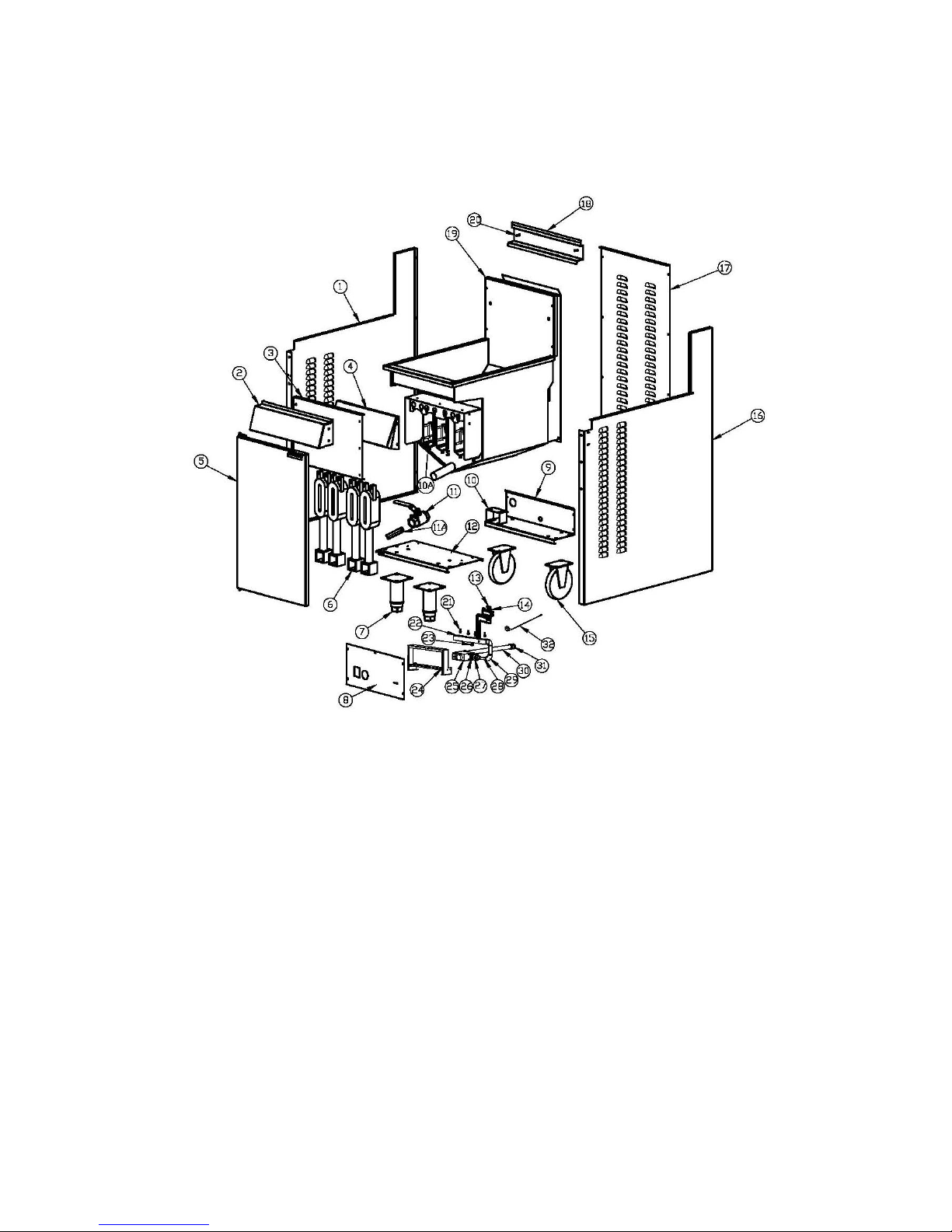
Onderdelentekening GF4
Gas fryer Manual Page 42
Page 43

Materiaallijst (GF4)
Item Beschrijving P/N tekening# Hoeveelh
eid
1 Linkerpaneel 10113062 1
2 Voorpaneel S15015 B-GF-GY02 1
3 Schild 10113055 1
4 Absorptieplaat vóór 10113044 1
5 Deur S01097 B-GF-MZJ-01 1
6 Brander B06181 B-GF-JS-01-11 4
7 Poten S99002 2
8 Bedieningspaneel 10113060 1
9 Onderkant
achterzijde
10113054 1
10 Beugel gasleiding 10113039 1
10A Interne
apsorptieplaat
B-JS-GF-01 4
11 Afvoerklep B09022 1
11A Afvoerbuis S15029 1
12 Voorzijde onderkant 10113007 1
13 Waakvlam B06362 1
14 Thermokoppel SIT-0.200.015 1
15 Casterwieltje B05080 2
16 Rechter paneel 10113053 1
17 Achterkant 10113014 1
18 Mandhanger 10113029 1
19 Friteuse assemblage S15013 B-GF4-GYGF4 1
20 Schroef S15012 2
21 Injector S15002 4
22 Spruitstuk
assemblage
B-GF4C-LJ03 1
23 Drukmeetpunt B06383 1
24 Spruitstuksteun 10113059 1
25 Gasklep B06330 1
26 Reducer B11089 1
27 Koppeling B14017 2
28 Gasleiding B-GF4C-LJ01 1
29 Elleboogstuk B12008 2
30 Gasinlaatbuis B-GF4-LJ01 1
31 Reducer B11014 1
32 Hoge limiet E03040
1
Gas fryer Manual Page 43
Page 44
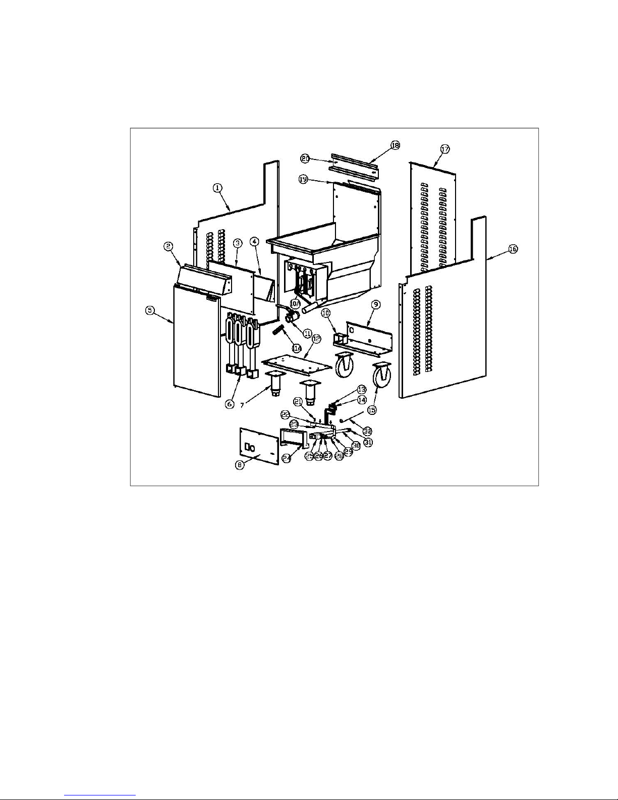
Onderdelentekening GF3 7455.0975
Gas fryer Manual Page 44
Page 45

Materiaallijst GF3 (7455.0975)
Item Description P/N Drawing # Qty
1 Linker paneel 10113062 1
2 Voorpaneel S15015 B-GF-GY02 1
3 Schild 10113055 1
4 Asorptieplaat vóór 10115013 1
5 Deur S01097 B-GF-MZJ-01 1
6 Brander B06181 B-GF-JS-01-11 3
7 Poten S99002 2
8 Bedieningspaneel E13155 1
9 Onderkant
achterzijde
10113054 1
10 Gasbuisbeugel 10113039 1
10A Interne
apsorptieplaat
B-JS-GF-01 3
11 Afvoerklep B09022 1
11A Afvoerbuis S15029 1
12 Voorzijde onderkant 10113007 1
13 Waakvlam B06362 1
14 Thermokoppel SIT-0.200.015 1
15 Casterwieltje B05080 2
16 Rechter paneel 10113053 1
17 Achterkant 10113014 1
18 Mandhanger 10113029 1
19 Friteuse assemblage S15016 B-GF3-RGGY 1
20 Schroef S15012 2
21 Injector S15002 3
22 Spruitstuk
assemblage
B-GF4C-LJ03 1
23 Drukmeetpunt B06383 1
24 Spruitstuksteun 10113059 1
25 Gasklep B06330 1
26 Reducer B11089 1
27 Koppel B14017 2
28 Gasleiding B-GF4C-LJ01 1
29 Elleboogstuk B12008 2
30 Gasinlaatbuis B-GF4-LJ01 1
31 Reducer B11014 1
32 Hoge limiet E03040
1
Gas fryer Manual Page 45
Page 46

N o t e s
_______________________________________________________________________
_______________________________________________________________________
_______________________________________________________________________
_______________________________________________________________________
_______________________________________________________________________
_______________________________________________________________________
_______________________________________________________________________
_______________________________________________________________________
_______________________________________________________________________
_______________________________________________________________________
_______________________________________________________________________
_______________________________________________________________________
_______________________________________________________________________
_______________________________________________________________________
_______________________________________________________________________
_______________________________________________________________________
_______________________________________________________________________
Gas fryer Manual Page 46
Page 47
MANUEL D’INSTALLATION,
D’UTILISATION ET D’ENTRETIEN
SERIES GF OU FRITEUSE AU
GAZ 7455.0975
AVERTISSEMENTS
UNE INSTALLATION, UNE ADAPTATION, UNE
MODIFICATION, UNE UTILISATION OU UN ENTRETIEN
INCORRECTS PEUVENT PROVOQUER DES LESIONS
OU LA MORT. LE MANUEL DOIT ETRE LU
ATTENTIVEMENT AVANT DE PROCEDER A
L’INSTALLATION, AU MANIEMENT OU A L’ENTRETIEN
DE CET APPAREIL
PEUT UNIQUEMENT ETRE INSTALLE PAR UNE
PERSONNE AGREEE CONFORMEMENT AUX
PRESCRIPTIONS DES AUTORITES LOCALES, A
TOUTES LES PRESCRIPTIONS LEGALES RELATIVES
AU GAZ ET A L’ELECTRICITE, ET AUX EXIGENCES DU
FABRICANT
CET APPAREIL A ÉTÉ REALISE POUR DES BESOINS DE
CATERING COMMERCIAUX ET GENERE UNE CHALEUR
TRES ELEVEE . L’APPAREIL DOIT ETRE UTILISE PAR
DES PERSONNES QUALIFIEES. LES SURFACES
CHAUDES PEUVENT OCCASIONNER DES BRULURES.
LES PROPRIETAIRES DOIVENT EFFECTUER UNE
ANALYSE DES DANGERS ET DES RISQUES, ET
PORTER CELLE-CI A LA CONNAISSANCE DE TOUS LES
UTILISATEURS.
Gas fryer Manual Page 47
Page 48
NE CONSERVEZ OU UTILISEZ AUCUN LIQUIDE
INFLAMMABLE A PROXIMITE DE CET APPAREIL.
LES ELEMENTS QUI SONT SECURISES PAR LE
FABRICANT OU SON REPRESENTANT NE PEUVENT
ETRE ADAPTES PAR L’UTILISATEUR.
NE DIFFUSEZ AUCUN AEROSOL A PROXIMITE DE CET
APPAREIL LORSQUE CELUI-CI EST EN COURS
D’UTILISATION.
LES VALEURS DE TOLERANCE D’INSTALLATION
INDIQUEES DOIVENT ETRE RESPECTEES.
EN CAS D’ODEUR DE GAZ, REFERMEZ LA VALVE
D’ALIMENTATION DE GAZ PRINCIPALE SUR
L’APPAREIL. PRENEZ CONTACT AVEC VOTRE
FOURNISSEUR DE GAZ OU UNE PERSONNE
AUTORISEE.
CONTROLEZ L’ APPAREIL AVANT D’OUVRIR LA VALVE
D’ALIMENTATION DE GAZ PRINCIPALE, POUR VOUS
ASSURER QUE TOUTES LES VALVES SONT EN
POSITION "OFF".
CONSERVEZ CE MANUEL A PORTEE DE MAIN
POUR CONSULTATION FUTURE ET COMME
REFERENCE POUR TOUT UTILISATEUR.
Gas fryer Manual Page 48
Page 49

TABLE DES MATIERES
INTRODUCTION.............................................................................................51
GENERALITES.............................................................................................51
GARANTIE....................................................................................................51
INFORMATION GENERALE...........................................................................52
INSPECTION................................................................................................52
MANUEL DE L’UTILISATEUR......................................................................52
INSTALLATION.............................................................................................52
RACCORDEMENT AU GAZ.........................................................................52
PRESSION DU GAZ.....................................................................................52
MISE EN SERVICE......................................................................................52
SPECIFICATIONS...........................................................................................53
INSTALLATION.............................................................................................54
SPECIFICATION DE RACCORDEMENT....................................................55
POINT DE TEST DE PRESSION.................................................................55
VENTILATION ET AERATION......................................................................55
DIMENSIONS...............................................................................................56
ACCESSOIRES............................................................................................56
MODE D’EMPLOI............................................................................................57
INSTRUCTIONS D’ALLUMAGE...................................................................57
PROCEDURE D’ALLUMAGE.......................................................................58
ENTRETIEN UTILISATEUR............................................................................61
NETTOYAGE DE L’INOX.............................................................................61
SERVICE.........................................................................................................62
SERVICE RECOMMANDE...........................................................................62
REGLAGE DU BRULEUR............................................................................63
PIECES DE RECHANGE.............................................................................64
RESOLUTION DE PROBLEMES....................................................................65
SCHEMA DETAILLE GF4................................................................................66
SCHEMA DETAILLE GF3................................................................................68
Gas fryer Manual Page 49
Page 50

INTRODUCTION
GENERALITES
Cette friteuse alimentée au gaz a été développée pour des besoins de
catering commerciaux et comporte un large éventail de fonctions au profit du
client.
GARANTIE
La garantie offerte sur ce produit est soumise aux conditions du distributeur
local dans le pays où vous résidez, et est liée à une installation, une
utilisation, un entretien et des soins corrects de l’appareil.
La garantie ne s’étend pas aux:
• dommages pendant l’expédition
• dommage résultant d’une installation incorrecte
• dommage résultant d’une utilisation inappropriée
• dommage causé par un service non compétent et l’utilisation de pièces qui
ne sont pas d’origine
• problèmes liés à l’alimentation du gaz vers l’appareil
• dérangements survenus suite à un entretien inapproprié
• dérangements résultant de la manipulation, de l’enlèvement ou de la
modification d’un équipement de contrôle ou de sécurité préinstallé.
Pour tout travail sous garantie, service autorisé et pièces de rechange
agréées et d’origine, prenez contact avec votre revendeur local.
Veillez à mentionner le modèle et le numéro de série de l’appareil. Le
modèle et le numéro de série de l’appareil se trouvent sur la plaquette
signalétique. Veuillez fournir ceux-ci au service après-vente.
Gas fryer Manual Page 50
Page 51

INFORMATION GENERALE
INSPECTION
Contrôlez l’appareil dès sa réception. Si l’appareil est endommagé, prenez
immédiatement contact avec le transporteur et remettez-lui une plainte. Lors
de l’introduction d’une plainte, conservez tout le matériel d’emballage. Les
plaintes pour dégât lors du transport sont de la responsabilité de l’acheteur et
ne sont pas couvertes par la garantie.
MANUEL DE L’UTILISATEUR
Ce manuel contient des informations importantes pour votre sécurité et
l’installation, l’utilisation, l’entretien et le service de cet appareil. Lisez le
manuel avec beaucoup d’attention et assurez-vous que tous les
utilisateurs de l’appareil sont au courant de son contenu et des
exigences relatives à la sécurité.
Avertissement: vous devez évaluer tous les dangers et les risques liés
au fonctionnement de l’appareil dans votre environnement et informer
tous les utilisateurs de vos constatations.
INSTALLATION
Cet appareil doit être installé par une personne agréée conformément à
toutes les prescriptions légales en vigueur dans le domaine de
l’électricité et du gaz imposées par les autorités locales et aux
exigences du fabricant.
RACCORDEMENT AU GAZ
L’appareil doit être raccordé par une personne agréée au type de gaz
mentionné sur l’appareil. Le type de gaz est indiqué à côté du point de
raccordement au gaz situé à l’arrière et sur la plaquette signalétique. Ne
raccordez et n’utilisez l’appareil qu’avec le type de gaz correct.
PRESSION DU GAZ
La personne agréée qui installe cet appareil doit s’assurer que la pression du
gaz correspond à celle indiquée sur la plaquette signalétique et que la
quantité de gaz disponible est suffisante.
Gas fryer Manual Page 51
Page 52
MISE EN SERVICE
La personne agréée qui installe cet appareil doit mettre celui-ci en service
conformément aux dispositions locales en matière de sécurité du gaz – fuite
de gaz, contrôle de fonctionnement, adaptations, et formation du propriétaire
quant à l’usage de l’appareil sont des exigences requises.
SPECIFICATIONS
INSTALLATION
CET APPAREIL DOIT ETRE INSTALLE PAR UNE PERSONNE
AGREEE CONFORMEMENT A TOUTES LES DISPOSITIONS
LEGALES EN VIGUEUR CONCERNANT LE GAZ ET
L’ELECTRICITE IMPOSEES PAR LES AUTORITES LOCALES,
ET AUX EXIGENCES DU FABRICANT.
REMARQUE: L’INSTALLATION EST DE LA RESPONSABILITE DU
PROPRIETAIRE
Connexion au gaz: BSP Femelle 1/2”.
Point de raccordement: le point de raccordement au gaz se trouve à
l’arrière de l’appareil. Les détails sont mentionnés
dans les schémas à l’arrière de ce manuel.
Raccordement au gaz: l’appareil doit être raccordé par une personne
agréée sur le type de gaz mentionné sur
l’appareil. Le type de gaz est indiqué à côté du
point de raccordement à l’arrière et sur la
plaquette signalétique. Ne raccordez et n’utiliser
l’appareil qu’avec le type de gaz correct.
La personne agréée qui installe cet appareil doit
respecter les normes locales de sécurité en
matière de gaz. Les prescriptions dans ce
domaine comprennent la mise en service de
l’appareil, le test de fuite de gaz, le contrôle de
fonctionnement et les réglages.
Gas fryer Manual Page 52
Page 53

Tous les appareils sont testés et réglés en usine; tous les brûleurs et
veilleuses doivent cependant être contrôlés à l’endroit de l’installation et être
réglés si nécessaire.
Plaquette d’information: la plaquette signalétique se trouve à l’arrière de la
friteuse
Distances d’installation: la distance MINIMUM par rapport à des surfaces
inflammables est de :
Latéralement 150 mm
A l’arrière 50mm.
Il faut également laisser libre un espace
suffisant pour l’entretien.
Mise de niveau: pour régler les pieds permettant de mettre
l’appareil de niveau et/ou pour régler la hauteur de
l’appareil, soulevez légèrement l’avant de
l’appareil et réglez les pieds (veillez à travailler en
toute sécurité). Soulevez l’arrière de l’appareil de
la même façon et réglez les pieds.
NE COUCHEZ PAS L’ APPAREIL SUR SON
DOS. VEILLEZ A CE QUE L’APPAREIL SOIT DE
NIVEAU.
Gas fryer Manual Page 53
Page 54

Spécification de raccordement
Nom du produit
Friteuse au gaz
Type d’appareil
Type A1
Catégorie de gaz
I
2H
I
2E
I
2L
I
2E+
Gaz et pression
d’alimentation
G20 à 20 mbar G20 à 20
mbar
G25 à 25
mbar
G20/G25 à
20/25 mbar
Pays de
destination
AT, BG, CR, CZ, DK,
EE, FI, GR, HR, HU, IS,
IE, IT, LV, LT, NO, PT,
RO, SK, SI, ES, SE, CH,
TR et GB
BE, FR NL DE, LU, PL
Taille injecteur Ø 2.3 mm Ø 2.3 mm Ø 2.2 mm Ø 2.2 mm
Consommation gaz 34kW pour GF4 ; 27KW pour GF3
Avertissement: cet appareil doit être installé conformément à la législation en vigueur et ne
peut être utilisé que dans un local bien ventilé. Consultez les instructions avant
installation et utilisation de cet appareil.
Niveau d’ignition de la veilleuse: 750W
Tableau de consommation nominale de gaz pour
I2H
(uniquement comme référence)
Brûleur Test alimentation de gaz Test point de pression
GF4 20 mbar 13.5 mbar
GF3 20 mbar 14.7 mbar
Remarque: le point de test de pression se trouve sur le collecteur (voir cidessous).
POINT DE TEST DE PRESSION
Le point de test de pression se trouve sur le collecteur de gaz et est
accessible en ouvrant la petite porte. La pression au point de test est indiquée
dans le tableau de consommation nominale de gaz ci-dessus et est réglée
avec les brûleurs au niveau maximum.
VENTILATION ET AERATION
Tous les brûleurs à gaz et les veilleuses nécessitent un apport d’air suffisant
pour fonctionner. Pour des performances optimales, et pour votre sécurité, il
est ESSENTIEL que l’appareil, dans la position installée, bénéficie d’une
ventilation et d’un apport d’air appropriés, ainsi que d’un bon équilibre entre
extraction et air. L’installation correcte et le respect de toute la législation et
autres exigences sont de la responsabilité de l’acheteur/propriétaire.
Tenez compte du fait qu’une extraction forte créera une aspiration si un
volume d’air suffisant n’est pas présent en remplacement. La quantité d’air
évacuée doit être remplacée par une quantité d’air équivalente.
Gas fryer Manual Page 54
Page 55

Le flux d’air dirigé vers l’appareil ne doit pas être bloqué ou limité (il ne faut
pas placer d’objets de grande dimensions devant l’appareil, par exemple). La
cheminée ne doit jamais être couverte ou encombrée de quelque manière.
DIMENSIONS
* Notez que les dimensions extérieures des GF3 et GF4 sont identiques.
* Les dimensions du produit sont 393 x 750 x 1160 mm
* Les dimensions de l’emballage sont 510 x 820 x 1230 mm
ACCESSOIRES
1.
Paniers à frites @2
2.
Grille @1
3.
Tuyau prolongateur pour huile @1
4.
Bouchon de désengorgements @1
5.
Mode d’emploi @1
Gas fryer Manual Page 55
Page 56
MODE D’EMPLOI
INSTRUCTIONS D’ALLUMAGE
NE METTEZ PAS L’APPAREIL EN ROUTE S’IL N’A PAS ÉTÉ
INSTALLE ET MIS EN SERVICE PAR UNE PERSONNE
AGREEE A CET EFFET.
AVANT D’OUVRIR L’ALIMENTATION DE GAZ, CONTROLEZ
QUE TOUT EST EN ORDRE ET VEILLEZ A CE QUE TOUTES
LES VALVES SOIENT EN POSITION "OFF".
CET APPAREIL A ÉTÉ CONCU POUR A DES FINS DE
CATERING COMMERCIALES ET GENERE UNE CHALEUR
CONSIDERABLE. LES SURFACES CHAUDES PEUVENT
OCCASIONNER DES BRULURES. LES PROPRIETAIRES
DOIVENT PROCEDER A UNE ANALYSE DES DANGERS ET
DES RISQUES, ET PORTER CELLE-CI A L’ATTENTION DE
TOUS LES UTILISATEURS.
NOTE: assurez-vous que l’alimentation au gaz de l’appareil est branchée
(“ON”).
NOTE: pour votre propre sécurité, la valve est pourvue d’un détecteur de
défaut de flamme. Si le senseur ne détecte pas de flamme,
l’alimentation de gaz vers le brûleur sera coupée.
Gas fryer Manual Page 56
Page 57
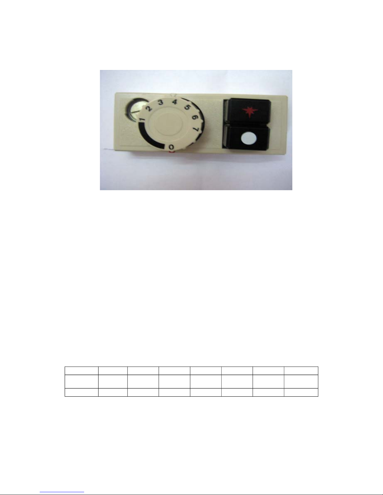
PROCEDURE D’ALLUMAGE
NOTE: assurez-vous que l’alimentation au gaz de l’appareil est branchée
(“ON”).
1) Commencer à la position "0".
2) Pousser sur la position ★ "VEILLEUSE" .
3) Allumez la veilleuse manuellement à l’aide d’un allumeur ou d’un briquet.
4) Maintenez le bouton ★ enfoncé pendant 15 secondes. Lorsque le bouton
★ est relâché, la veilleuse doit rester allumée. Si ce n’est pas le cas,
retournez à l’étape (1) et recommencer depuis le début. Lorsque La valve
automatique détecte que la veilleuse est allumée, l’arrivée de gaz au brûleur
principal est ouverte.
5) Si la veilleuse ne peut être allumée après des essais répétés, voyez la
page « résolution de problèmes » de ce manuel.
6) Tournez le bouton sur le réglage “1”.
7) Tournez le bouton jusqu’au point de réglage correspondant à la
température souhaitée. Consultez le tableau suivant.
Réglage 1 2 3 4 5 6 7
o
C 120 135 145 160 175 185 195
o
F 248 275 293 320 347 365 383
Lorsque l’huile atteint la température souhaitée (normalement, le brûleur
principal est à cet instant coupé temporairement), la friteuse peut être
chargée.
Gas fryer Manual Page 57
Page 58

Avertissement:
Lorsqu’il se sert de cette friteuse, l’utilisateur doit suivre la procédure
Prenez les plus grandes précautions lors du chargement des aliments
dans la friteuse afin d’éviter des brûlures dues aux projections d’huile.
Suspendez le panier à frites à son support jusqu’à ce que l’huile se soit
égouttée.
Ne surchargez pas le panier à frites.
Position en veilleuse standby
Pour éteindre le brûleur principal et maintenir la veilleuse allumée (”ON”),
tournez le bouton sur la position "0".
Extinction/Veilleuse OFF
– Tourner le bouton de commande sur la position "0".
- Déclencher le bouton « VEILLEUSE ». L’alimentation de gaz aussi bien vers
le brûleur principal que vers la veilleuse sera coupée simultanément.
NOTE: si la veilleuse s’éteint accidentellement, le détecteur de défaut de
flamme entre en fonction et coupe l’alimentation vers le brûleur principal.
Dans ce cas, la veilleuse doit être à nouveau allumée en suivant la procédure
ci-dessus.
Attendez environ 15 secondes jusqu’à ce que la valve soit revenue en
position normale.
Recommencez la PROCEDURE D’ALLUMAGE à partir de l’étape (1).
Extinction thermique d’urgence:
Attendez environ 10 minutes pour laisser refroidir l’huile.
Poussez sur le bouton de l’interrupteur thermique. Si l’interrupteur thermique
ne peut pas être réactivé manuellement, appelez votre agent d’entretien.
Répétez l’étape (1) de le PROCEDURE D’ALLUMAGE pour rallumer la
friteuse.
Gas fryer Manual Page 58
Page 59

Ajout d’huile
Attention: remplissez d’huile le vase de la friteuse jusqu’à un niveau situé
entre le maximum et le minimum.
Attention: n’utilisez pas d’huile concentrée ou de graisse. Seule de l’huile
liquide peut être utilisée dans cette friteuse.
Procédure de filtrage de l’huile:
4) Eteignez la friteuse et laissez-la refroidir environ 20 minutes
5) Vissez le tuyau prolongateur pour la vidange de l’huile (accroché à
l’intérieur de la porte) dans le couvercle de la valve de vidange
6) Veillez à ce que l’embouchure du tuyau de vidange arrive dans un bac
de récolte d’huile (ou dans un panier de filtrage d’huile)
Tirez sur la poignée de sécurité du levier et commencez à tourner lentement
la poignée vers la gauche. ATTENTION: NE TOURNEZ PAS LA POIGNEE
TROP VITE. CECI PEUT AVOIR POUR EFFET QUE DE L’HUILE CHAUDE
S’ECOULE EN-DEHORS DE L’EMBOUCHURE DE VIDANGE.
Filtrage de l’huile
L’huile doit être filtrée régulièrement pour prolonger sa durée de vie utile. Cela
diminuera aussi les coûts de fonctionnement. Les facteurs suivants
contribuent tous à écourter la durée de vie de l’huile.
← Contact avec l’air.
← Débris d’aliments et particules carbonisés.
← Contact avec toute autre surface que de l’inox.
← Contact avec des aromates, des épices et du sel.
← Cuisson d’aliments à une température trop élevée.
Gas fryer Manual Page 59
Page 60
ENTRETIEN D’UTILISATION
UTILISEZ UNIQUEMENT DES MATIERES CHIMIQUES
APPROPRIEES ET RESPECTEZ LES CONSIGNES DE
SECURITE DU FABRICANT POUR LE MANIEMENT ET
L’UTILISATION DE L’APPAREIL EN TOUTE SECURITE.
Avertissement: assurez-vous que l’appareil est débranché et que les
éléments sont assez refroidis pour les toucher.
11)
Evitez les projections d’eau sur tous les éléments et les tuyaux.
12)
Contrôlez régulièrement les raccordements et les circuits de gaz.
13)
Evitez le bouchage de l’évacuation des fumées. D’éventuels obstacles
dans l’évacuation de fumée peuvent causer une combustion incomplète.
14)
Assurez-vous que le type et la pression du gaz sont conformes aux
spécifications indiquées sur la plaquette signalétique.
Il faut procéder à un nettoyage régulier et approfondi pour un fonctionnement
sûr et efficace de l’appareil, et pour prévenir des flambées. L’intensité de
l’usage et la nature des produits mis à frire déterminent en grande partie la
fréquence et la nécessité d’un nettoyage complet. A vous de juger de cela.
Pour le nettoyage des éléments, utilisez un détergent approprié, de l’eau
chaude et une brosse à récurer. Il est nécessaire de répéter l’opération si les
dépôts sont importants et carbonisés.
NETTOYAGE DE L’INOX
Essuyez régulièrement la surface avec de l’eau chaude et un détergent.
Rincez la partie lavée avec une éponge humide et de l’eau propre, et séchez
la surface pour prévenir des rayures. Suivez ce procédé et lavez une petite
surface à la fois pour éviter résidus chimiques et rayures.
L’inox peut déteindre en cas de surchauffe. Ces souillures peuvent en général
être enlevées à l’aide d’une poudre/pâte appropriée. Pour gratter un dépôt
important de graisse et d’huile, n’utilisez que des outils en bois ou en
plastique pour autant que nécessaire.
Note: n’utilisez jamais d’éponge de fer pour nettoyer l’inox.
Note: des dégâts peuvent se produire en cas d’utilisation de substances
chimiques non appropriées pour l’inox.
Gas fryer Manual Page 60
Page 61
SERVICE
POUR VOTRE PROPRE SECURITE, TOUS LES TRAVAUX DE
SERVICE DOIVENT ETRE REALISES UNIQUEMENT PAR UNE
PERSONNE AGREEE, ET SEULS DES ELEMENTS FOURNIS
D’ORIGINE ET SPECIFIES PEUVENT ETRE UTILISES.
TESTEZ TOUS LES RACCORDS, TUYAUX ET MANCHONS
POUR LES FUITES CONFORMEMENT AUX PROCEDES ET
METHODES AGREES EN MATIERE DE FUITE DE GAZ.
N’UTILISEZ PAS DE FLAMME.
SERVICE RECOMMANDE
Il est recommandé de faire examiner votre appareil tous les 12 mois par une
personne agréée. Cette période est seulement donnée à titre indicatif et peur
varier selon l’usage qui est fait de l’appareil et le soin y apporté par
l’utilisateur. Les tâches de service prescrites comprennent :
•
le test fonctionnel de tous les composants, nettoyage et réglage si
nécessaire ;
•
le contrôle, le nettoyage de toutes les valves à gaz ainsi que leur
lubrification à l’aide d’un produit lubrifiant agréé par l’industrie ;
•
le contrôle de toutes les conduites de gaz ;
•
le contrôle et le réglage des pressions de gaz spécifiées ;
•
le test de fuites ;
•
un test complet de fonctionnement opérationnel, de performance et de
sécurité.
Gas fryer Manual Page 61
Page 62

REGLAGES DE BRULEUR
Test de fuites
1) Assurez-vous que toutes les valves de réglage sont en position “OFF”.
2) Ouvrez le robinet général d’alimentation du gaz.
3) Allumez toutes les veilleuses.
4) Procédez au test de fuite toutes les valves et raccords selon des
méthodes agréées.
5) Corrigez les défauts éventuels comme exigé et contrôlez à nouveau.
6) Fermez toutes les valves et mettez les boutons de réglage sur "OFF".
Point de mesure de pression
Le point de test de pression se trouve sur le collecteur de gaz. Le collecteur
de gaz et le point de test sont accessibles en ouvrant la porte de la friteuse.
La pression au point de test est indiquée dans le ‘Tableau de consommation
de gaz nominale’ et est réglée avec les brûleurs à leur niveau maximum.
Réglage de la veilleuse
Réglez toutes les veilleuses de telle sorte que la flamme enveloppe la tête du
thermocouple en tournant la vis de réglage de la flamme de la veilleuse située
sur la valve du gaz, dans le sens des aiguilles d’une montre pour diminuer,
dans le sens inverse pour augmenter.
Ce réglage n’est nécessaire qu’en cas de remplacement de la valve du gaz
ou de conversion à un type de gaz différent.
Réglage du brûleur
Les orifices du brûleur sont déterminés comme spécifié, et ne peuvent être
ajustés. Le débit de gaz spécifié sera atteint si la pression du gaz et la
pression au point de test sont corrects.
Une flamme bleue bien claire couvrant entièrement la surface du brûleur sera
obtenue à plein débit si l’apport d’air est correct et si l’injecteur et le brûleur
sont alignés de manière appropriée.
Si la flamme est jaune et ondoyante, il faut en rechercher la cause.
AVERTISSEMENT: si vous n’êtes pas apte à réaliser les opérations de
service ou si vous avez besoin d’aide, prenez contact avec votre agent
d’entretien local.
Gas fryer Manual Page 62
Page 63

PIECES DE RECHANGE
Vous trouverez une liste des pièces de rechange les plus importantes à la fin
de ce manuel.
Vous pouvez obtenir ces pièces, ainsi que tous les autres éléments
constituant la friteuse, chez votre revendeur local.
Avertissement: n’utilisez que des pièces d’origine. L’utilisation de
pièces non autorisées annule la garantie et l’agréation de l’appareil.
Gas fryer Manual Page 63
Page 64
RESOLUTION DE PROBLEMES
TOUTE OPERATION DE SERVICE DOIT ETRE EFFECTUEE
PAR UNE PERSONNE AGREEE.
BRULEURS
SITUATION CONTROLE
Veilleuse ne s’allume pas. Alimentation gaz branchée et pression du
gaz correcte
Veilleuses bouchées
Vis de réglage de la veilleuse
Extinction veilleuse à répétition Taille et position de la flamme de la
veilleuse
Thermocouple
Détecteur de sécurité de la flamme
Flamme du brûleur jaune Air primaire
Flamme en-dehors de la surface
du brûleur Air primaire
Eclats après extinction Air primaire
Flamme du brûleur trop grande Pression du gaz
Retard à l’allumage Flamme de la veilleuse
Nettoyage du brûleur et des orifices
Pression du gaz
Retour de flamme vers orifices Air primaire
Gas fryer Manual Page 64
Page 65
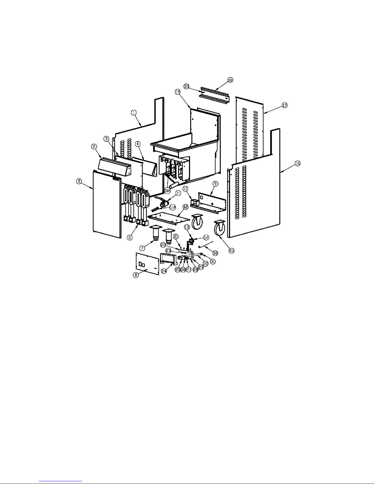
Schéma détaillé GF4
Gas fryer Manual Page 65
Page 66

Liste du matériel (GF4)
Item Description P/N Schéma # Quantité
1 Panneau gauche 10113062 1
2 Panneau avant S15015 B-GF-GY02 1
3 Bouclier 10113055 1
4 Déflecteur avant 10113044 1
5 Porte S01097 B-GF-MZJ-01 1
6 Brûleur B06181 B-GF-JS-01-11 4
7 Pied S99002 2
8 Panneau de contrôle 10113060 1
9 Fonds arrière 10113054 1
10 Support tuyau gaz 10113039 1
10A Déflecteur interne B-JS-GF-01 4
11 Clapet de vidange B09022 1
11A Tuyau de vidange S15029 1
12 Fonds avant 10113007 1
13 Veilleuse B06362 1
14 Thermocouple SIT-0.200.015 1
15 Roulette B05080 2
16 Panneau droit 10113053 1
17 Arrière 10113014 1
18 Porte panier 10113029 1
19 Assemblage vase
friteuse
S15013 B-GF4-GYGF4 1
20 Vis S15012 2
21 Injecteur S15002 4
22 Assemblage
collecteur
B-GF4C-LJ03 1
23 Point de test de
pression
B06383 1
24 Support collecteur 10113059 1
25 Valve à gaz B06330 1
26 Réducteur B11089 1
27 Coupleur B14017 2
28 Tuyau de gaz B-GF4C-LJ01 1
29 Coude B12008 2
30 Connexion gaz B-GF4-LJ01 1
31 Réducteur B11014 1
32 Limite haute E03040
1
Gas fryer Manual Page 66
Page 67
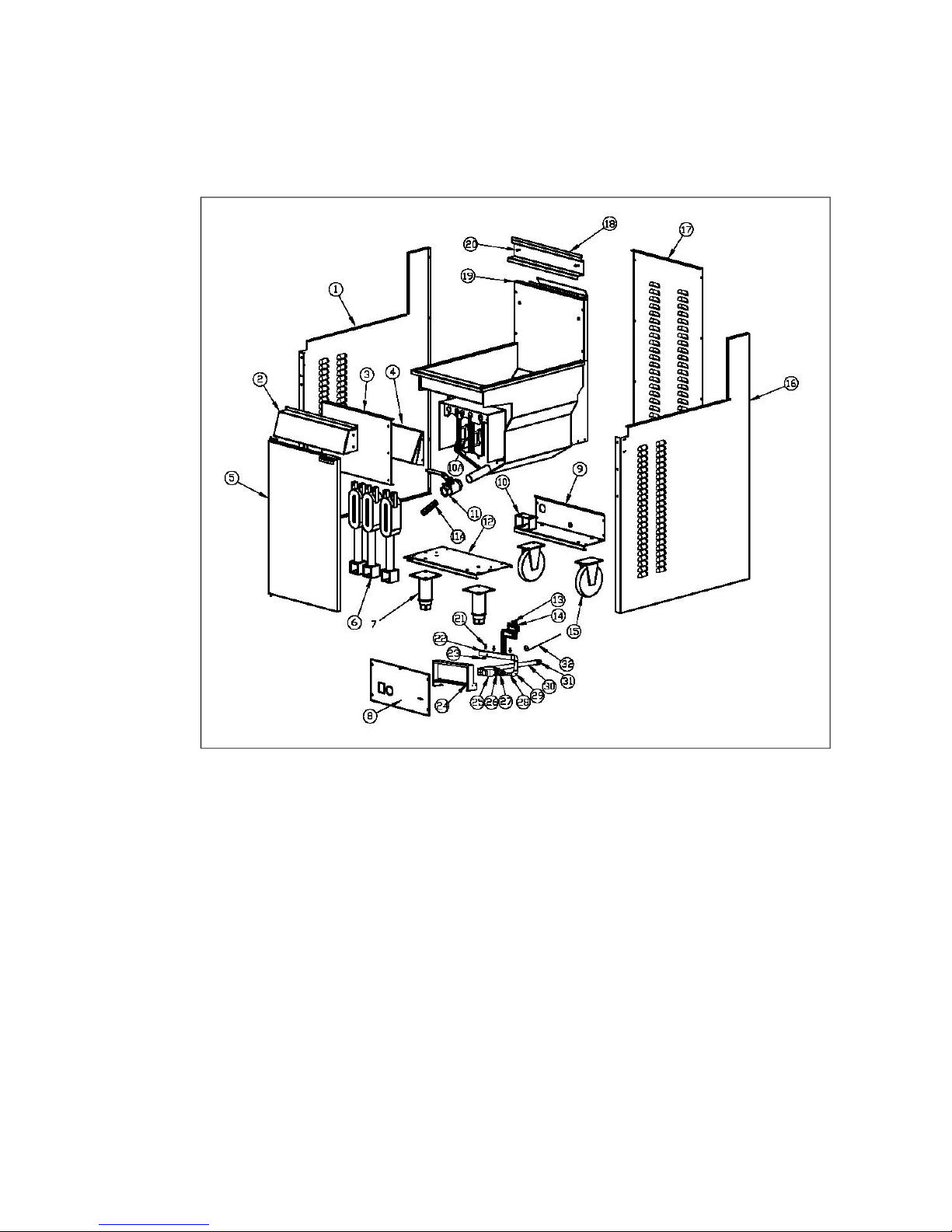
Schéma détaillé GF3 7455.0975
Gas fryer Manual Page 67
Page 68

Liste du matériel GF3 (7455.0975)
Item Description P/N Schéma # Quantité
1 Panneau gauche 10113062 1
2 Panneau avant S15015 B-GF-GY02 1
3 Bouclier 10113055 1
4 Déflecteur avant 10115013 1
5 Porte S01097 B-GF-MZJ-01 1
6 Brûleur B06181 B-GF-JS-01-11 3
7 Pied S99002 2
8 Panneau de contrôle E13155 1
9 Fonds arrière 10113054 1
10 Support tuyau gaz 10113039 1
10A Déflecteur interne B-JS-GF-01 3
11 Clapet de vidange B09022 1
11A Tuyau de vidange S15029 1
12 Fonds avant 10113007 1
13 Veilleuse B06362 1
14 Thermocouple SIT-0.200.015 1
15 Roulette B05080 2
16 Panneau droit 10113053 1
17 Arrière 10113014 1
18 Porte panier 10113029 1
19 Assemblage vase
friteuse
S15016 B-GF3-RGGY 1
20 Vis S15012 2
21 Injecteur S15002 3
22 Assemblage
collecteur
B-GF4C-LJ03 1
23 Point de test de
pression
B06383 1
24 Support collecteur 10113059 1
25 Valve à gaz B06330 1
26 Réducteur B11089 1
27 Coupleur B14017 2
28 Tuyau de gaz B-GF4C-LJ01 1
29 Coude B12008 2
30 Connexion gaz B-GF4-LJ01 1
31 Réducteur B11014 1
32 Limite haute E03040
1
Gas fryer Manual Page 68
Page 69

N o t e s
_______________________________________________________________________
_______________________________________________________________________
_______________________________________________________________________
_______________________________________________________________________
_______________________________________________________________________
_______________________________________________________________________
_______________________________________________________________________
_______________________________________________________________________
_______________________________________________________________________
_______________________________________________________________________
_______________________________________________________________________
_______________________________________________________________________
_______________________________________________________________________
_______________________________________________________________________
_______________________________________________________________________
_______________________________________________________________________
_______________________________________________________________________
Gas fryer Manual Page 69
 Loading...