

Page 1

CriticalPoint Public Safety DAS
DISTRIBUTED ANTENNA
SYSTEM
USER MANUAL
Public Safety DAS RH-7W22 Class A QE: 1-0-0
Comba Telecom Ltd.
Page 2

The information contained herein is the responsibility of and is approved by the
following, to whom all enquiries should be directed:
This is an unpublished work the copyright in which vests in Comba International
("Comba"). All rights reserved.
The information contained herein is confidential and the property of Comba and is
supplied without liability for errors or omissions. No part may be reproduced,
disclosed or used except as authorized by contract or other written permission. The
copyright and the foregoing restriction on reproduction and use extend to all media
in which the information may be embodied.
Page 3

INSTALLATION GUIDE FOR RH-7W22
ENU STATUS : 1-0-0
Copyright - refer to title page
Page 3
Section
Page
0.1 CONTENTS
0.1 CONTENTS ................................................................................................................................. 3
0.2 INDEX TO FIGURES AND TABLES ......................................................................................... 5
0.3 HISTORY ..................................................................................................................................... 7
0.4 GLOSSARY OF TERMS ............................................................................................................ 8
0.5 SAFETY NOTICES AND ADMONISHMENTS ......................................................................... 9
1 GENERAL INFORMATION ................................................................ ...................................... 11
2 EQUIPMENT DESCRIPTION .................................................................................................. 13
2.1 SYSTEM DIAGRAM.................................................................................................................. 13
2.2 EQUIPMENT LAYOUT ................................................................ ............................................. 14
2.3 EQUIPMENT CONSTITUTION ................................................................................................ 16
3 INSTALLATION ......................................................................................................................... 17
3.1 WARNINGS AND ALERTS ................................................................ ...................................... 17
3.2 SITE PLANNING CONSIDERATIONS .................................................................................... 18
3.2.1 SITE PLANNING ....................................................................................................................... 18
3.2.2 INSTALLATION CHECKLIST................................................................................................... 19
3.3 INSTALLATION PROCEDURES ............................................................................................. 20
3.3.1 GOODS INWARDS INSPECTION........................................................................................... 20
3.3.2 TOOLS ....................................................................................................................................... 20
3.3.3 PREPARATION ......................................................................................................................... 20
3.3.4 WALL MOUNTING .................................................................................................................... 21
3.3.5 DRIP-LOOP ............................................................................................................................... 21
3.4 EQUIPMENT CONNECTORS ................................................................................................. 22
3.4.1 PS DAS CONNECTORS .......................................................................................................... 22
3.4.2 PS DAS LED Indicators ............................................................................................................ 24
3.4.3 GROUNDING CONNECTION .................................................................................................. 24
3.4.4 RF CABLE CONNECTION ................................ ....................................................................... 24
3.4.5 ETHERNET CONNECTION ..................................................................................................... 24
4 COMMISSIONING .................................................................................................................... 25
4.1 PRE-COMMISSIONING TASKS .............................................................................................. 25
4.2 COMMISSIONING PROCEDURE ........................................................................................... 26
5 WEB GUI ................................................................................................................................... 28
5.1 WEB GUI CONNECTION ......................................................................................................... 28
5.2 WEB GUI INTRODUCTION ..................................................................................................... 29
5.2.1 [TOPOLOGY][PARAMETER INFORMATION] ....................................................................... 29
5.2.2 [TOPOLOGY][FUNCTION] ................................ ....................................................................... 36
5.2.3 [TOPOLOGY][PROGRAM INFO] ............................................................................................. 41
5.2.4 [AUTO SETUP].......................................................................................................................... 41
5.2.5 [SYSTEM] .................................................................................................................................. 47
6 MAINTENANCE ................................................................................................ ........................ 51
7 APPENDICES ........................................................................................................................... 52
7.1 APPENDIX A: TOOLS .............................................................................................................. 52
Page 4

INSTALLATION GUIDE FOR RH-7W22
ENU STATUS : 1-0-0
Copyright - refer to title page
Page 4
7.2 APPENDIX B: DECLARATION OF HARMFUL SUBSTANCES AND CONTENT ............... 53
7.3 APPENDIX C: LICENSE SWITCH QUICK GUIDE ................................................................ 54
7.4 APPENDIX D: RMA (RETURN MATERIAL AUTHORIZATION) ........................................... 56
Page 5

INSTALLATION GUIDE FOR RH-7W22
ENU STATUS : 1-0-0
Copyright - refer to title page
Page 5
0.2 INDEX TO FIGURES AND TABLES
Figure 1: Master Unit (MU) ........................................................................................................................ 11
Figure 2: Remote Unit (RU) ....................................................................................................................... 12
Figure 3: PS DAS Functional Block Diagram ............................................................................................... 13
Figure 4: Layout of the MU Bottom layer ..................................................................................................... 14
Figure 5: Layout of the MU middle layer ...................................................................................................... 14
Figure 6: Layout of the MU top layer ........................................................................................................... 15
Figure 7: Layout of the RU Bottom layer ..................................................................................................... 15
Figure 8: Layout of the RU top layer............................................................................................................ 16
Figure 9: Mounting Rack Overview ............................................................................................................. 20
Figure 10: PS DAS Wall Mounting .............................................................................................................. 21
Figure 11: MU Equipment Connectors ........................................................................................................ 22
Figure 12: RU Equipment Connectors ......................................................................................................... 23
Figure 13: Commissioning Procedure ......................................................................................................... 26
Figure 14: Input IP Address ........................................................................................................................ 28
Figure 15: Input Domain Name ................................................................................................................... 28
Figure 16: Input User Name and Password ................................................................................................. 28
Figure 17: Web GUI Main Screen ............................................................................................................... 29
Figure 18: Overview Screen – MU .............................................................................................................. 30
Figure 19: Overview Screen – MU .............................................................................................................. 30
Figure 20: Overview Screen – RU ............................................................................................................... 31
Figure 21: Device alarm - MU ..................................................................................................................... 31
Figure 22: Device alarm - RU ...................................................................................................................... 32
Figure 23: 800MHz Screen - MU................................................................................................................. 32
Figure 24: 800MHz Screen - RU ................................................................................................................. 33
Figure 25: 700MHz Screen - MU................................................................................................................. 34
Figure 26: 700MHz Screen - RU ................................................................................................................. 34
Figure 27: Optical Information – MU............................................................................................................ 35
Figure 28: Optical Information – RU ............................................................................................................ 35
Figure 29: [Function] Screen ....................................................................................................................... 36
Figure 30: Function – Device Info ............................................................................................................... 36
Figure 31: Function – Import & Export ......................................................................................................... 37
Figure 32: Function – Summary .................................................................................................................. 37
Figure 33: Function – Comm. Setting .......................................................................................................... 38
Figure 34: Function –Reset ......................................................................................................................... 38
Figure 35: Function – Firmware Upgrade .................................................................................................... 39
Figure 36: Function – Log ........................................................................................................................... 39
Figure 37: Function – Alarm Setting ............................................................................................................ 40
Figure 38: Function – License ..................................................................................................................... 40
Figure 39: Program Information .................................................................................................................. 41
Figure 40: Commissioning Procedure – Start .............................................................................................. 42
Figure 41: Commissioning Procedure – Scan ............................................................................................. 43
Figure 42: Commissioning Procedure – Isolation Detection ......................................................................... 44
Figure 43: Device Information Setting ......................................................................................................... 45
Figure 44: MU Parameter Setting ................................................................................................................ 46
Figure 45: RU Parameter Setting ................................................................................................................ 46
Figure 46: Finish ......................................................................................................................................... 47
Figure 47: System – Import & Export .......................................................................................................... 47
Figure 48: System – Summary .................................................................................................................... 48
Figure 49: System – Scan ........................................................................................................................... 48
Figure 50: System – Remove ...................................................................................................................... 48
Figure 51: System – Firmware .................................................................................................................... 49
Figure 52: System – Log ............................................................................................................................. 49
Figure 53: System – Isolation...................................................................................................................... 49
Page 6

INSTALLATION GUIDE FOR RH-7W22
ENU STATUS : 1-0-0
Copyright - refer to title page
Page 6
Figure 54: Input User Name and Password ................................................................................................. 54
Figure 55: Input License Code .................................................................................................................... 55
Figure 56: License switch success .............................................................................................................. 55
Table 1: MU Equipment Connectors ........................................................................................................... 22
Table 2: RU Equipment Connectors ............................................................................................................ 23
Table 3: LED Indicators .............................................................................................................................. 24
Table 4: Commissioning Task Explanation .................................................................................................. 27
Page 7

INSTALLATION GUIDE FOR RH-7W22
ENU STATUS : 1-0-0
Copyright - refer to title page
Page 7
Change No.
ENU
Details Of Change
1
1-0-0
This manual first created and issued in Dec 2017.
.
0.3 HISTORY
Page 8

INSTALLATION GUIDE FOR RH-7W22
ENU STATUS : 1-0-0
Copyright - refer to title page
Page 8
Abbreviation
Definition
ALC
Automatic Level Control
ATT
Attenuator
BTS
Base Transceiver Station
CH
Channel
CSA
Cross Sectional Area
dB
Decibel
dBm
Decibels relative to 1 milliwatt
DL
Downlink
DT
Donor Terminal
DPX
Duplexer
FOU
Fiber Optical Unit
FS
Frequency Selection
Hz
Hertz
ID
Identification
IF
Intermediate Frequency
LNA
Low Noise Amplifier
LOS
Line-of-Sight
MCU
Main Control Unit
MHz
Megahertz
MT
Mobile Terminal
MTBF
Mean Time Between Failures
MU
Master Unit
NF
Noise Figure
OMC
Operation & Maintenance Center
OMT
Operation & Maintenance Terminal
OP
Optical Fiber
PA
Power Amplifier
PLL
Phase Locked Loop
PSU
Power Supply Unit
RF
Radio Frequency
RFU
Radio Frequency Unit
RU
Remote Unit
SMA
Sub-Miniature A Connector
TX/RX
Transmit/Receive
UL
Uplink
VAC
Volts Alternating Current
VDC
Volts Direct Current
VSWR
Voltage Standing Wave Ratio
0.4 GLOSSARY OF TERMS
Page 9

INSTALLATION GUIDE FOR RH-7W22
ENU STATUS : 1-0-0
Page 9
0.5 SAFETY NOTICES AND ADMONISHMENTS
This document contains safety notices in accordance with appropriate standards. In the interests of conformity
with the territory standards for the country concerned, the equivalent territorial admonishments are also shown.
Any installation, adjustment, maintenance and repair of the equipment must only be carried out by trained,
authorized personnel. At all times, personnel must comply with any safety notices and instructions.
Specific hazards are indicated by symbol labels on or near the affected parts of the equipment. The labels
conform to international standards, are triangular in shape, and are colored black on a yellow background. An
informative text label may accompany the symbol label.
Hazard labeling is supplemented by safety notices in the appropriate equipment manual. These notices contain
additional information on the nature of the hazard and may also specify precautions.
Note: The grantee is not responsible for any changes or modifications not expressly approved by the party
responsible for compliance. Such modifications could void the user’s authority to operate the equipment.
For compliance with the occupational/controlled RF exposure limits, each individual antenna used for this
transmitter must be installed to provide a separation distance greater than 20 cm or more from all persons
during normal operation and must not be co-located with any other antenna for meeting RF exposure
requirements.
Warning Notices:
These draw the attention of personnel to hazards that may cause death or injury to the operator or others.
Examples of use are cases of high voltage, laser emission, toxic substances, point of high temperature, etc.
The design of the antenna installation needs to be implemented in such a way so as to ensure RF radiation
safety levels and non-environmental pollution during operation.
Note: Antennas, feeders and couplers are not included in the packing list; solution provider should consider
these accessories according to site conditions.
WARNING! This is NOT a CONSUMER device. It is designed for installation by FCC LICENSEES and
QUALIFIED INSTALLERS. You MUST have an FCC LICENSE or express consent of an FCC Licensee to
operate this device. Unauthorized use may result in significant forfeiture penalties, including penalties in
excess of $100,000 for each continuing violation.
Note: The grantee is not responsible for any changes or modifications not expressly approved by the party
responsible for compliance. Such modifications could void the user’s authority to operate the equipment.
Alert:
These draw the attention of personnel to hazards that may cause damage to the equipment. An example of use
is the case of static electricity hazard.
Caution notices may also be used in the handbook to draw attention to matters that do not constitute a risk of
causing damage to the equipment but where there is a possibility of seriously impairing its performance, e.g. by
mishandling or gross maladjustment. Warnings and Cautions within the main text do not incorporate labels and
may be in shortened form.
Disconnection of the RU RF connectors may cause damage to the equipment when power is on.
The application antenna and RF cable are not provided.
The antenna gain should not exceed 9dBi for uplink and should not exceed 4dBi for downlink
Copyright - refer to title page
Page 10

INSTALLATION GUIDE FOR RH-7W22
ENU STATUS : 1-0-0
Copyright - refer to title page
Page 10
WARNING!
Use only authorized and approved antennas, cables and/or coupling devices! The use of unapproved antennas,
cables or coupling devices could cause damage and may be of violation of FCC regulations. The use of
unapproved antennas, cables and/or coupling devices is illegal under FCC regulations and may subject the
user to fines.
End of Section
Page 11

INSTALLATION GUIDE FOR RH-7W22
ENU STATUS : 1-0-0
Copyright - refer to title page
Page 11
1 GENERAL INFORMATION
The Public Safety Distributed Antenna System RH-7W22 (hereinafter called “PS DAS”) consists of Master Unit
(MU) and Remote Unit (RU). The MU includes the MU Chassis, Power Supply Unit (PSU), Fiber Optical
module and RF module. Optical module with a modular design, it can support up to 8 independent Remote
Units. The Remote Unit is designed with a compact form for easy installation; it is an integrated design which
supports 2 independent bands, 700MHz and 800MHz.
The low signal transmission loss of optical fiber is applicable for long distance transmission. PS DAS can
support the optical transmission of up to 6.5dBo optical loss, equivalent to 8 miles fiber length.
Main Features
Dual-band configuration supports 700MHz and 800MHz public safety bands
Supports P25 P1/P2 digital and conventional analog communications simultaneously
Supports FirstNetTM LTE Band 14 (Class B)
Up to 32 channels (Class A) / 3 sub bands (Class B)
Channelized Auto Level Control (ALC) supported (Class A)
Channelized uplink squelch supported (Class A)
Web based GUI for intelligent configuration, SNMP supported
Built-in mandatory isolation test to prevent oscillation
NFPA 1221 compliant dry contact alarms on MU / RUs
NFPA 1221 compliant NEMA 4X enclosure for MU / RUs
Alarming output to supervised circuits for: antenna failure, signal booster failure, and etc.
The following figure shows the enclosure of the PS DAS Master unit and Remote unit.
Figure 1: Master Unit (MU)
Page 12

INSTALLATION GUIDE FOR RH-7W22
ENU STATUS : 1-0-0
Copyright - refer to title page
Page 12
Figure 2: Remote Unit (RU)
End of Section
Page 13
INSTALLATION GUIDE FOR RH-7W22
ENU STATUS : 1-0-0
Copyright - refer to title page
Page 13
… …
Remote Unit
Remote Unit
Master Unit
Up to 8
2 EQUIPMENT DESCRIPTION
2.1 SYSTEM DIAGRAM
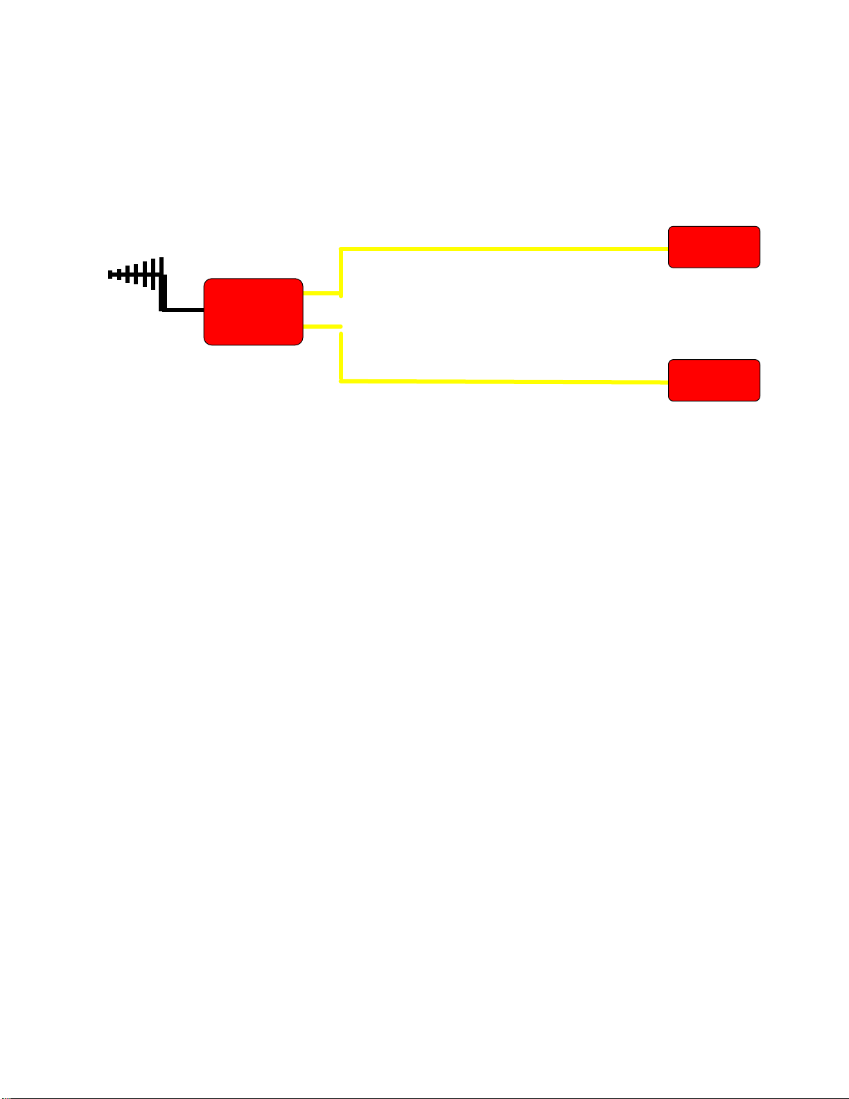
Figure 3: PS DAS Functional Block Diagram
In the downlink path, the BTS signals are received by the donor antenna of the Master Unit. After the duplexer,
the signals are sent to the LNA module for pre-amplification and to the digital RF integrated module for digital
filtering and frequency conversion. Then the DL signals will be sent to the Remote Unit to amplify power by
optical fiber, and filter via the duplexer. After amplification, the signals are transmitted at the MT port to the
service antenna.
In the uplink path, the mobile signals are received by the service antenna. After the MT port duplexer, the
signals are sent to the LNA, integrated module for digital filtering, then the UL signals will be sent to the Master
Unit for power amplification and to the duplexer. After that, the uplink signals are sent to the donor antenna for
transmission back to the BTS.
The devices can detect output power, refer to expect output power which is set by user, the device can reduce
or increase internal ATT automatically and remain the expected output power. This is the AGC principle.
Page 14
INSTALLATION GUIDE FOR RH-7W22
ENU STATUS : 1-0-0
Copyright - refer to title page
Page 14
MU Bottom Layer
MU Middle Layer
Integrated Module
Integrated Module
Power Supply
Module
Surge Arrestor
Duplexer
MCU
Combiner
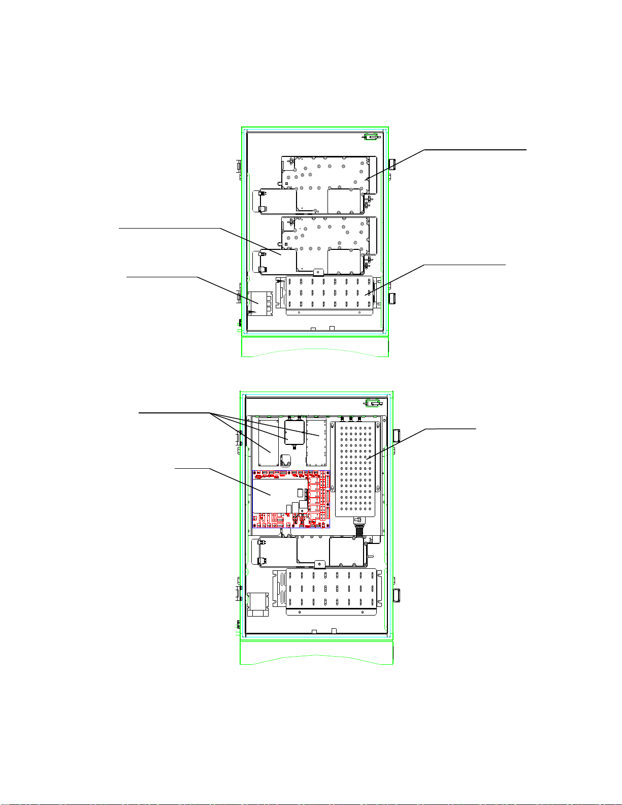
2.2 EQUIPMENT LAYOUT
Shown below is the internal layout of the PS DAS.
Figure 4: Layout of the MU Bottom layer
Figure 5: Layout of the MU middle layer
Page 15
INSTALLATION GUIDE FOR RH-7W22
ENU STATUS : 1-0-0
Copyright - refer to title page
Page 15
MU Top Layer
RU底层
Optical Module
FSK Module
Integrated Module
Integrated Module
Power Supply
Module
Surge Arrestor
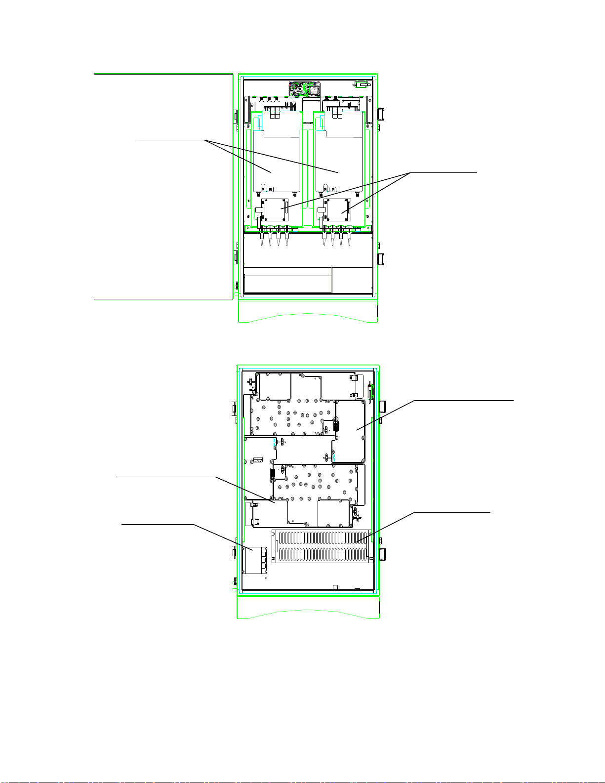
Figure 6: Layout of the MU top layer
Figure 7: Layout of the RU Bottom layer
Page 16
INSTALLATION GUIDE FOR RH-7W22
ENU STATUS : 1-0-0
Copyright - refer to title page
Page 16
Optical Module
Adaptor Module
FSK Module
Duplexer
Combiner
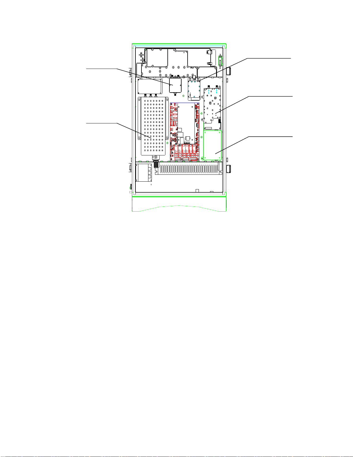
Figure 8: Layout of the RU top layer
2.3 EQUIPMENT CONSTITUTION
The typical PS DAS unit consists of the following components:
Power Amplifier (PA): It provides power amplification for both the UL and DL branches.
Main Control Unit (MCU): The MCU is used to monitor and control the operation of the repeater. It also
provides the communication interface for remote control and status indication. LED indicators provide the
operation status of the MCU.
Duplexer: The DPX is located near the MT and DT terminals and permits the uplink and downlink signals to
share a common antenna.
Digital Integrated Module and Power Amplifier: Consists of the Power Conversion module, RF module,
digital process module and monitoring modules. The Power Conversion module converts +28V DC voltage into
+9VJK and +9VRF. +9VJK, +9VRF are supplied to the monitoring unit, and the RF unit in the integrated module
separately. The RF module amplifies and converts the RF signal to IF signal. The Digital process module
converts the IF signal into baseband signal via AD conversion and extraction, and filtering. After that, the IF
signal will be amplified and converted to an RF signal by the RF module for RF filtering and amplification. The
Monitoring module monitors and controls the system parameters and is the interface for both remote
monitoring and local commissioning.
Power Supply Unit (PSU): The PSU converts the input voltage into a stable DC supply to provide power for
the internal functional modules.
Optical module: Completes optical signal and RF signal conversion.
Page 17

INSTALLATION GUIDE FOR RH-7W22
ENU STATUS : 1-0-0
Copyright - refer to title page
Page 17
3 INSTALLATION
3.1 WARNINGS AND ALERTS
Radio Frequency Energies
There may be situations, particularly for workplace environments near high-powered RF sources, where
recommended limits for safe exposure of human beings to RF energy could be exceeded. In such cases,
restrictive measures or actions may be necessary to ensure the safe use of RF energy.
High Voltage
The equipment has been designed and constructed to prevent, as far as reasonably practicable danger. Any
work activity on or near equipment involving installation, operation or maintenance must be, as far as
reasonable, free from danger.
Where there is a risk of damage to electrical systems involving adverse weather, extreme temperatures, wet,
corrosive or dirty conditions, flammable or explosive atmospheres, the system must be suitably installed to
prevent danger.
Protective Earthing
Equipment provided for the purpose of protecting individuals from electrical risk must be suitable for the
purpose and properly maintained and used.
Handling Precautions
This covers a range of activities including lifting, lowering, pushing, pulling, carrying, moving, holding or
restraining an object, animal or person from the equipment. It also covers activities that require the use of force
or effort, such as pulling a lever, or operating power tools.
Where some of the abovementioned activities are required, the equipment must be handled with care to avoid
being damaged.
Electrostatic Discharge (ESD)
Observe standard precautions for handling ESD-sensitive devices. Assume that all solid-state electronic
devices are ESD-sensitive. Ensure the use of a grounded wrist strap or equivalent while working with
ESD-sensitive devices. Transport, store, and handle ESD-sensitive devices in static-safe environments.
Page 18

INSTALLATION GUIDE FOR RH-7W22
ENU STATUS : 1-0-0
Copyright - refer to title page
Page 18
3.2 SITE PLANNING CONSIDERATIONS
3.2.1 SITE PLANNING
Site Considerations
Outdoor equipment are designed to be waterproof, rainproof, and with snow protection. Temporary protection
should be taken when the equipment enclosure is opened for installation or maintenance in an outdoor
environment. The equipment must not be opened for installation or maintenance in bad weather (e.g. gale,
storm rainfall, extreme temperatures and high humidity)
Installation Location
Mounting surface shall be capable of supporting the weight of the equipment.
In order to avoid electromagnetic interference, a proper mounting location must be selected to minimize
interference from electromagnetic sources such as large electrical equipment.
Environmental
Humidity has an adverse effect on the reliability of the equipment. It is recommended to install the equipment in
locations having stable temperature and unrestricted air-flow.
The installation location for the product should be well ventilated. The equipment has been designed to operate
at the temperature range and humidity level as stated in the product specifications in the datasheet.
Direct sun light exposure to the equipment should be avoided. Provide additional shelter if necessary.
Power Supply
The power supply unit (PSU) provides power to all modules within the equipment. Depending on the product
variant, it is recommended that the PSU be operated on a dedicated circuit breaker or fused circuit.
Grounding Requirement
Verify that the equipment has been well grounded. This includes antennas and all cables connected to the
system. Ensure lightning protection for the antennas is properly grounded.
Cable Routing
Depending on equipment configuration, a variety of types of cables are required. Where applicable, ensure
cables are properly routed and secured so that they are not damaged.
Manual Handling
During transportation and installation, take necessary handling precautions to avoid potential physical injury to
the installation personnel and the equipment.
Page 19

INSTALLATION GUIDE FOR RH-7W22
ENU STATUS : 1-0-0
Copyright - refer to title page
Page 19
3.2.2 INSTALLATION CHECKLIST
Working space available for installation and maintenance for each mounting arrangement. Ensure
unrestricted airflow.
Ensure earth ground point is within reach of the ground wire.
Ensure a power source is within reach of the power cord and the power source has sufficient capacity.
Where appropriate, ensure unused RF connectors are terminated.
Do not locate the equipment near large transformers or motors that may cause electromagnetic
interference.
Reduce signal loss in feeder cable by minimizing the length and number of RF connections.
Ensure VSWR of antennas system < 1.5:1.
Ensure equipment will be operated within the stated environment (see datasheet)
Observe handling of all cables to prevent damage.
Donor antenna should have a narrow beamwidth and positioned in line-of-sight (LOS) to the donor BTS site
so that the donor signal level is maximized. This allows the use of minimum gain to achieve the maximum
DL output power. The UL gain is typically set lower than or equal to the DL gain to minimize noise
interference to the donor BTS
Service antennas should be selected based on the type of service area, e.g., indoor antenna for indoor
application, and panel antenna for outdoor application.
Page 20
INSTALLATION GUIDE FOR RH-7W22
ENU STATUS : 1-0-0
Copyright - refer to title page
Page 20
3.3 INSTALLATION PROCEDURES
3.3.1 GOODS INWARDS INSPECTION
Verify the number of packages received against the packing list.
Check all packages for external damage; report any external damage to the shipping courier. If there is
damage, a shipping agent should be present before unpacking and inspecting the contents because
damage during transit is the responsibility of the agent.
Open and check each package against the packing list. If any items are missing, contact Comba.
Do not remove items from anti-static packing until ready for installation. If damage is discovered at the
time of installation, contact the shipping agent.
3.3.2 TOOLS
See Appendix A for a full list of the recommended tools required for installation and routine maintenance.
3.3.3 PREPARATION
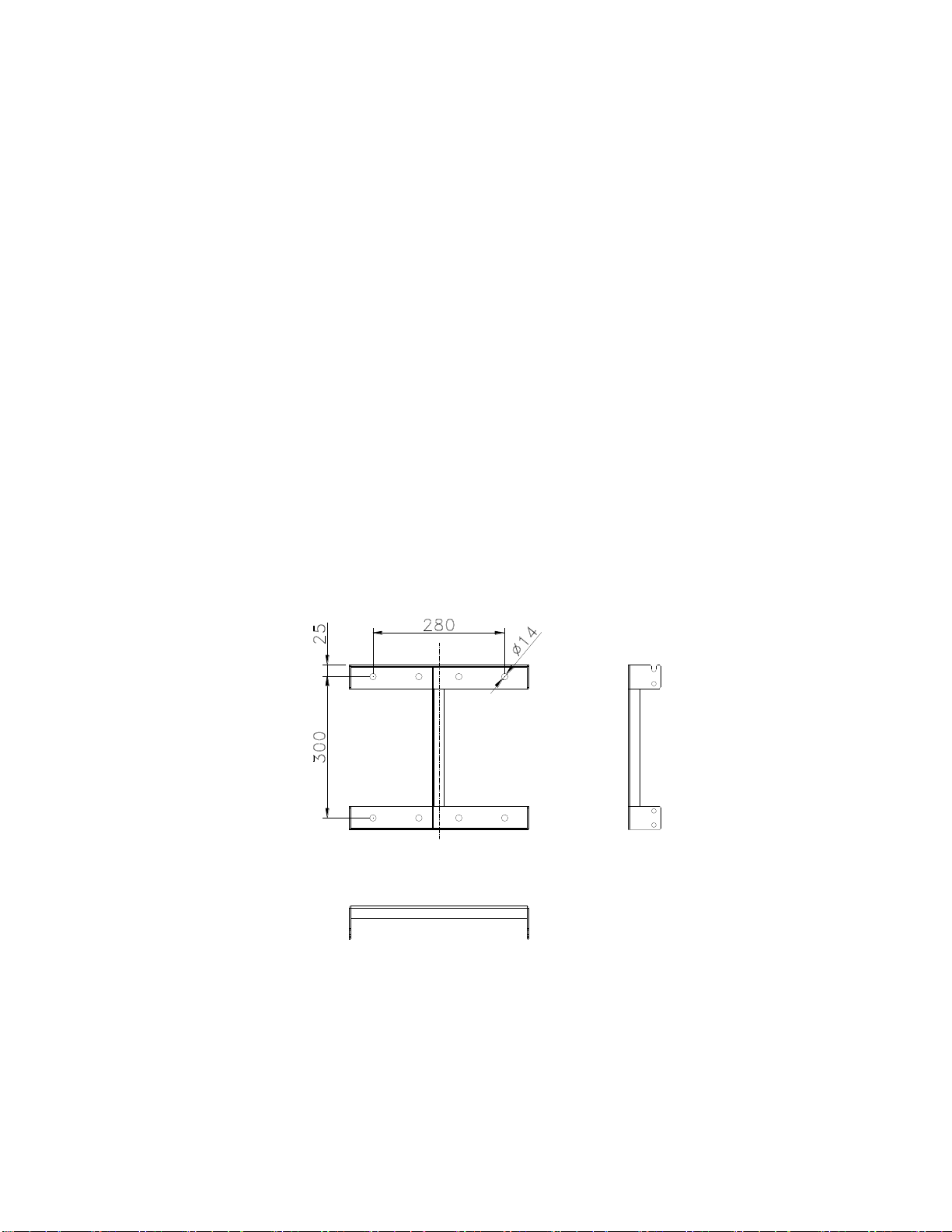
Wall mounting with the masonry bolts supplied, which make use of the outer holes.
Figure 9: Mounting Rack Overview
Page 21
INSTALLATION GUIDE FOR RH-7W22
ENU STATUS : 1-0-0
Copyright - refer to title page
Page 21
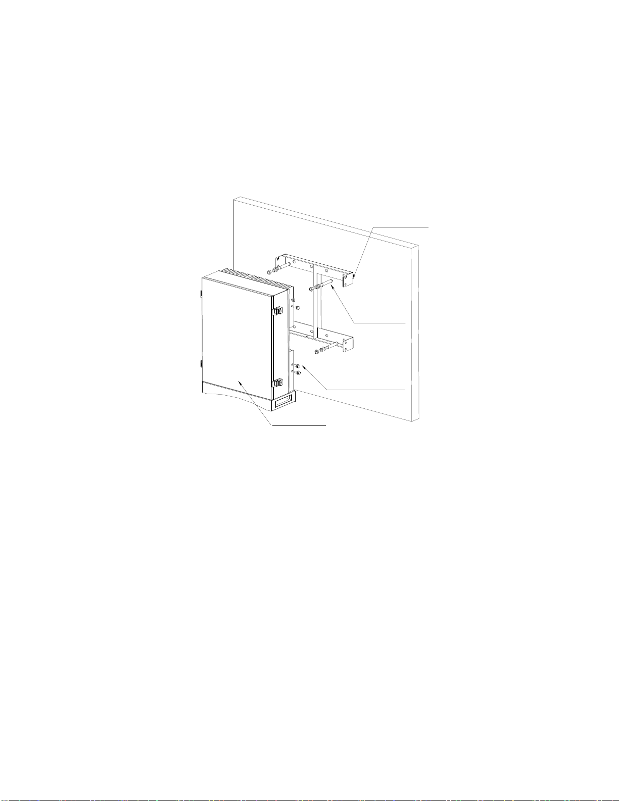
Mounting Rack
Masonry bolt
4-M10x110
6-M8x25, Hex socket
with washer bolt
RH-7W22
3.3.4 WALL MOUNTING
Drill four holes on the wall using the position of four holes on the mounting rack as a guide. Fix the
mounting rack to the wall using four masonry bolts (M10x110mm).
Install the Mounting Rack to the wall.
Hang the equipment and secure the enclosure to the mounting rack.
Figure 10: PS DAS Wall Mounting
3.3.5 DRIP-LOOP
Comba recommends that every horizontal cable entry to the equipment forms a 'U' before its entry to the
equipment. Water on the cable will drip down at the bottom of the loop and will not accumulate at the equipment
connectors.
Page 22

INSTALLATION GUIDE FOR RH-7W22
ENU STATUS : 1-0-0
Copyright - refer to title page
Page 22
Identifier
Descriptions
Power1
Power cable connector for a pre-installed power cord for connection to AC
(e.g. DC -48V).
DT
N-Female connector for connection to donor antenna.
Test
SMA connector for DT port test, -22dB coupling to DT port, available for both downlink
and uplink test.
TX_EXT/RX_EXT
Extensive RF Unit RF connectors, available for both downlink and uplink test.
FOU_UL/FOU_DL
Extensive Fiber Unit RF connectors, available for both downlink and uplink test.
OP
SC/APC optical fiber access port.
ALM1
Connector for connection to dry contact alarm 1-3.
ALM2
Connector for connection to dry contact alarm 4-6.
AUX1
Connector for connection to external alarm 1-4.
AUX2-4
Connector for extensive units.
AUX5
SMA connector for antenna connecting status detection
LAN
RJ45 Connector for internet connection (Ethernet type only).
1
3.4 EQUIPMENT CONNECTORS
3.4.1 PS DAS CONNECTORS
The PS DAS is designed for all cable entries from the right or left of the enclosure, as shown in the following
figure.
Figure 11: MU Equipment Connectors
Table 1: MU Equipment Connectors
The voltage identification is a variant due to electricity system diversity of global regions. The power cable connector might
be identified for AC 110V, AC 220V, AC 110V/220V, or DC -48V respectively. Please refer to specific product or contact
local sales if any doubt.
Page 23

INSTALLATION GUIDE FOR RH-7W22
ENU STATUS : 1-0-0
Copyright - refer to title page
Page 23
OMT
RJ45 Connector for local WEB GUI connection.
OP1~OP2
Optical fiber access port
Identifier
Descriptions
Power1
Power cable connector for a pre-installed power cord for connection to AC
(e.g. DC -48V).
MT
N-Female connector for connection to service antenna.
Test
SMA connector for MT port test, -22dB coupling to MT port, available for both
downlink and uplink test.
TX_EXT/RX_EXT
Extensive RF Unit RF connectors, available for both downlink and uplink test.
IN1/OUT1/IN2/OUT2
SMA connector for external filters.
ALM1
Connector for connection to dry contact alarm 1-3.
ALM2
Connector for connection to dry contact alarm 4-6.
AUX1
Connector for connection to external alarm 1-4.
AUX2-3
Connector for extensive units.
AUX4
SMA connector for antenna connecting status detection
OMT
RJ45 Connector for local WEB GUI connection.
OP
SC/APC optical fiber access port.
1
Figure 12: RU Equipment Connectors
Table 2: RU Equipment Connectors
The voltage identification is a variant due to electricity system diversity of global regions. The power cable connector might
be identified for AC 110V, AC 220V, AC 110V/220V, or DC -48V respectively. Please refer to specific product or contact
local sales if any doubt.
Page 24
INSTALLATION GUIDE FOR RH-7W22
ENU STATUS : 1-0-0
Copyright - refer to title page
Page 24
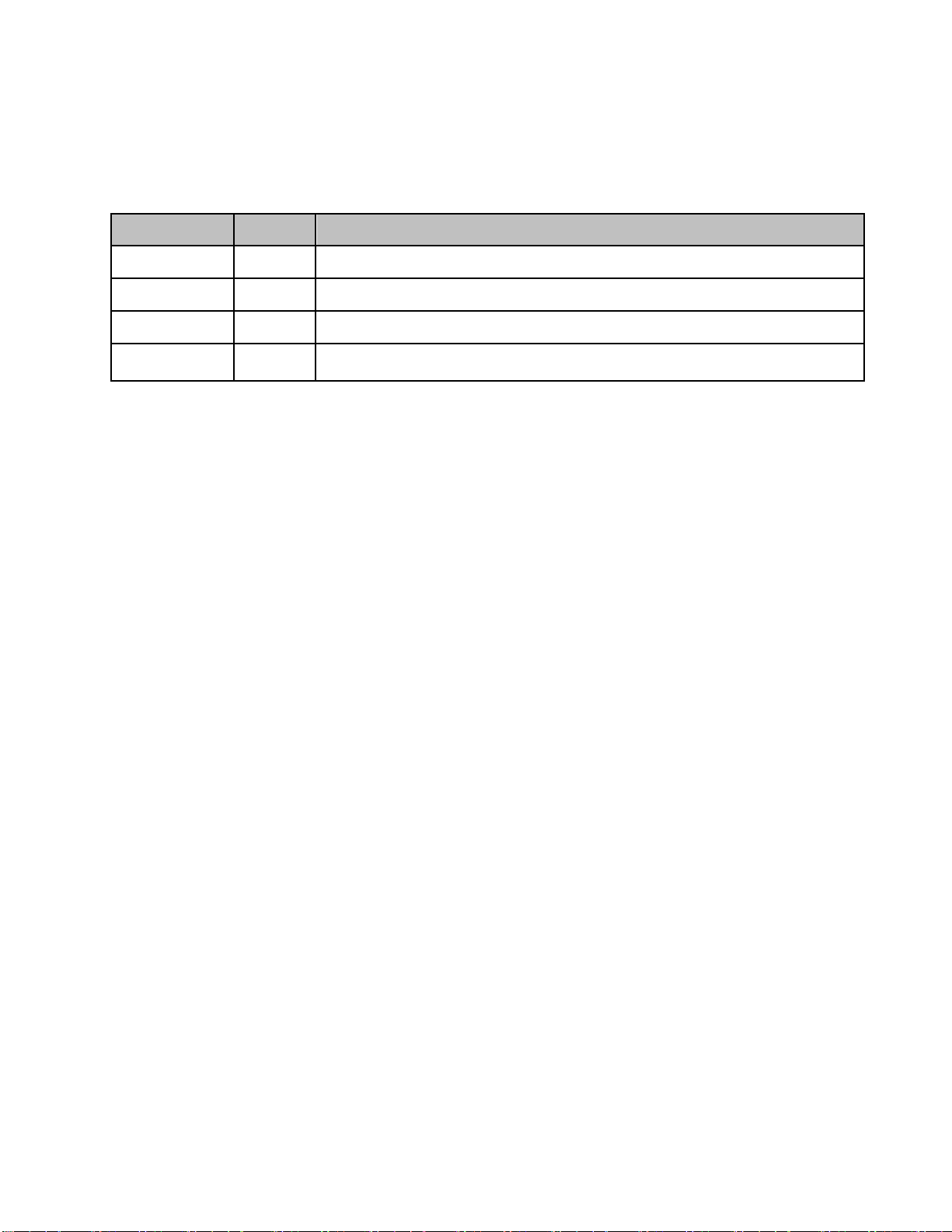
Identifier
Colour
Indication
PWR
Green
Power indicator. ON = power on; OFF = power off.
RUN
Green
Operation indicator, flashes every second to indicate normal operation.
ALM
Red
Alarm indicator. ON = alarm; OFF = no alarm.
OP
Green
Indicator for receive optical power. If LED is off, it indicates the receiving
optical power is less than -10dBm.
3.4.2 PS DAS LED Indicators
The LED indicators help user to check the equipment status easily.
Table 3: LED Indicators
3.4.3 GROUNDING CONNECTION
Ground Connection
To ensure safe operation of the product, a ground (earth) connection is required. For single phase AC power
source, the product must be grounded by connecting the “earth wire” of the power cord to the ground terminal
of the AC supply. For operating this product with DC power system (such as rectifiers), the product should not
be connected to power systems that switch open the return lead because the return lead could function as the
ground (earth) connection for the equipment.
Protective Ground Connection
The enclosure must be grounded securely by connecting a copper wire (CSA 16mm2) to the grounding terminal
on the equipment/rack, and the other end to a protective ground (i.e. building earth point). An internationally
acceptable color code of the ground connection wire is green/yellow.
Such a ground connection implements the “Protective Ground Connection”, and must be connected to the
equipment at the designated ground point. In general, do not connect the supply before establishing an
adequate ground (earth) connection.
Construct the ground wire, and use appropriate crimp connectors where necessary. Locate and connect the
equipment grounding terminal to a protective ground (i.e. building earth point).
3.4.4 RF CABLE CONNECTION
Single band PS DAS RF cables connection is as follows:
PS DAS MU DT port Connects to the feeder cable from donor antennas.
PS DAS RU MT port Connects to the feeder cable from service antennas.
3.4.5 ETHERNET CONNECTION
Connect Ethernet with ‘LAN’ port in the panel, Ethernet type only.
End of Section
Page 25

INSTALLATION GUIDE FOR RH-7W22
ENU STATUS : 1-0-0
Copyright - refer to title page
Page 25
4 COMMISSIONING
4.1 PRE-COMMISSIONING TASKS
After equipment installation, perform the following steps before equipment powering and commissioning:
Verify that the expected voltage, current and power levels do not violate any ratings.
Visually inspect the power connection within the equipment. Ensure that the power cable is correctly and
securely connected, including the grounding wire, RF cable and other cables.
Check the grounding connection and verify that the ground resistance is less than 5Ω.
Test the antenna system and ensure that the echo loss within working frequency is less than -14dB
(VSWR<1.5).
Page 26
INSTALLATION GUIDE FOR RH-7W22
ENU STATUS : 1-0-0
Copyright - refer to title page
Page 26
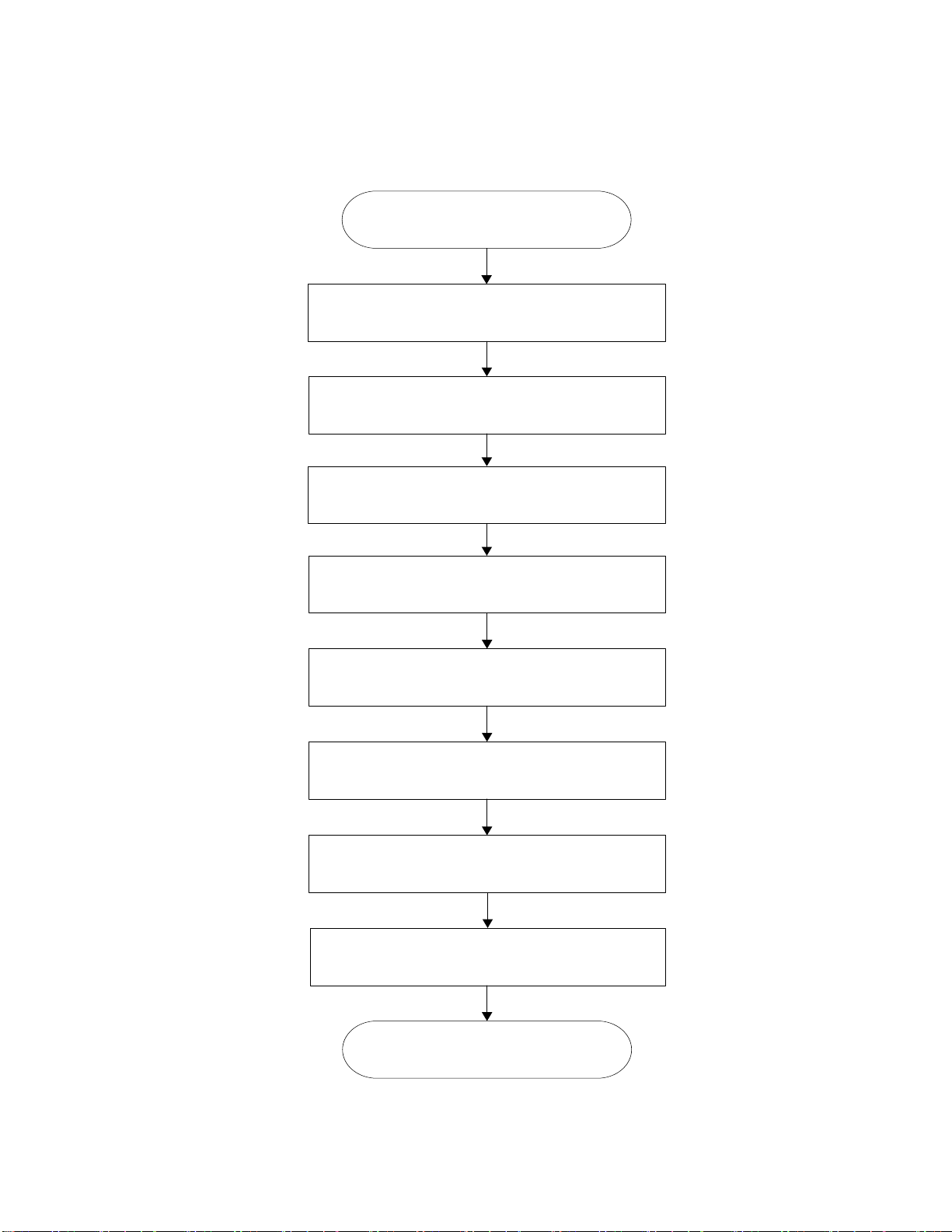
Start commissioning guide in WEB GUI
Isolation detection
Input power detection from control channel
Set channel total numbers
Get the recommended DL and UL parameters
Set frequency and gain for each channel in ‘Device’
page, and turn on RF switches
Fine tuning DL/UL gains for channels
End
Set Control channel frequency
Set unit parameters
4.2 COMMISSIONING PROCEDURE
Perform the following procedures for system commissioning.
Figure 13: Commissioning Procedure
Page 27

INSTALLATION GUIDE FOR RH-7W22
ENU STATUS : 1-0-0
Copyright - refer to title page
Page 27
Commissioning Tasks
Observation
1. Isolation detection
Detect isolation of service antenna and donor antenna.
2. Set control channel
frequencies
Enter the center frequency of the main control channel, the
commissioning guide will provide recommended DL/UL gain settings
based on main control channel input power and the total channel
numbers.
Users can skip this step and directly finish the commissioning guide
even if the frequency information or the total channel numbers are
unknown. Users are able to set the DL/UL gain manually any time
after the isolation detection has been completed and passed.
3. Set Channel No.
Enter the total channel numbers
4. Recommended DL and UL
gain parameters
The commissioning guide will provide recommended DL/UL gain
settings.
Users will still need to set all the gains manually in the “Device” pages,
and the frequencies for all the independent channels in the same
“Device” pages after the commissioning process is finished.
Table 4: Commissioning Task Explanation
End of Section
Page 28

INSTALLATION GUIDE FOR RH-7W22
ENU STATUS : 1-0-0
Copyright - refer to title page
Page 28
5 WEB GUI
The PS DAS can be monitored and controlled via the WEB GUI; use the following guide to finish system
parameter setting and commissioning.
5.1 WEB GUI CONNECTION
Step 1: Connect the OMT port to the PC RJ45 port with the supplied RJ45 cable to set up a physical
connection.
Step 2: Open a browser (suggested Firefox browser, display resolution is 1024×768), input Web GUI IP
address: 192.168.8.101, click [Enter].
NOTE: DHCP and DNS are also available to login to the Web GUI. The domain name is: www.combaomt.com.
Figure 14: Input IP Address
Figure 15: Input Domain Name
Step 3: Input User Name: admin; Password (default password: admin). Click [Log in].
Figure 16: Input User Name and Password
Page 29

INSTALLATION GUIDE FOR RH-7W22
ENU STATUS : 1-0-0
Copyright - refer to title page
Page 29
Indicates RU
quantities
5.2 WEB GUI INTRODUCTION
After log in, the Web GUI main screen will appear.
Figure 17: Web GUI Main Screen
On Comba Web GUI Home Screen, there are three Menu bars:
[Topology], [Auto Setup] and [System].
5.2.1 [TOPOLOGY][PARAMETER INFORMATION]
The [Topology] Screen shows the equipment status, such as setting status, alarm information, etc.
Overview Screen
Page 30

INSTALLATION GUIDE FOR RH-7W22
ENU STATUS : 1-0-0
Copyright - refer to title page
Page 30
Click to enable
/disable alarm
Indicating
product status
Param
Control Area
Click to change
setting value
Click to enable
/disable alarm
Indicating
product status
Param
Control Area
Click to change
setting value
Figure 18: Overview Screen – MU
Figure 19: Overview Screen – MU
Page 31
INSTALLATION GUIDE FOR RH-7W22
ENU STATUS : 1-0-0
Copyright - refer to title page
Page 31
Click to enable
/disable alarm
Indicating
product status
Parameter
control area
Click to change
setting value
Device Alarm
Figure 20: Overview Screen – RU
Figure 21: Device alarm - MU
Page 32
INSTALLATION GUIDE FOR RH-7W22
ENU STATUS : 1-0-0
Copyright - refer to title page
Page 32
Sub band
information
Center frequency
information
Bandwidth
information
RF
parameters
Click to set
Click to
setting
Figure 22: Device alarm - RU
800MHz Screen
This screen is only available for the dual band PS DAS or 800MHz PS DAS.
Figure 23: 800MHz Screen - MU
initiate batch
bandwidth,
UL/DL ATT,
enable/disabl
Page 33

INSTALLATION GUIDE FOR RH-7W22
ENU STATUS : 1-0-0
Copyright - refer to title page
Page 33
Figure 24: 800MHz Screen - RU
700MHz Screen
This screen is only available for the dual band PS DAS or 700MHz PS DAS.
Page 34
INSTALLATION GUIDE FOR RH-7W22
ENU STATUS : 1-0-0
Copyright - refer to title page
Page 34
Sub band
information
Center frequency
information
Bandwidth
information
RF
parameters
Click to set
Click to
setting
initiate batch
bandwidth,
UL/DL ATT,
enable/disabl
Figure 25: 700MHz Screen - MU
Figure 26: 700MHz Screen - RU
Page 35
INSTALLATION GUIDE FOR RH-7W22
ENU STATUS : 1-0-0
Copyright - refer to title page
Page 35
Optical
parameters
Rx/Tx Alarm
status
Click to
alarm
Optical Information
enable/disable
Figure 27: Optical Information – MU
Figure 28: Optical Information – RU
Page 36
INSTALLATION GUIDE FOR RH-7W22
ENU STATUS : 1-0-0
Copyright - refer to title page
Page 36
Click here to get
PC time.
Input device
information.
Management menu, click
parameters setting.
5.2.2 [TOPOLOGY][FUNCTION]
Other parameters can be configured on the [Function] Screen.
There are nine function bars list on the middle of the [Function] Screen.
Figure 29: [Function] Screen
Device Info
to enter each page for
Figure 30: Function – Device Info
Page 37

INSTALLATION GUIDE FOR RH-7W22
ENU STATUS : 1-0-0
Copyright - refer to title page
Page 37
Click to create summary
report
Inport&Export
Figure 31: Function – Import & Export
The parameters that can be imported / exported include sub band, alarm enable, ATT value, RF switch, and DL
output power.
This function can help users quickly configure PS DAS parameters. For example, if one PS DAS is finished
configuration, users can export the parameters and save it as a file on the PC, and then import this file to other
PS DASs for faster set up of additional PS DASs.
Summary
Note: Click Create to create the report and make sure that PDF Reader software is installed on the computer. If
not, the report will not be visible.
The device basic information, an overview of RF information and sub-band RF information are included in this
report. Please refer to appendix D for an example of device report.
Figure 32: Function – Summary
Page 38

INSTALLATION GUIDE FOR RH-7W22
ENU STATUS : 1-0-0
Copyright - refer to title page
Page 38
Comm. Setting
Figure 33: Function – Comm. Setting
Note: There are 4 available communication types: SMS, PS, SNMP and ETHERNET. You can choose a
suitable type for remote monitoring.
Reset
Note: Click Next, all the parameters and alarms will be reset to factory default value. The Device Reset
process will last about 2~4 minutes. For PMU monitor reset, users need to re-login to the WEB GUI.
Figure 34: Function –Reset
Page 39
INSTALLATION GUIDE FOR RH-7W22
ENU STATUS : 1-0-0
Copyright - refer to title page
Page 39
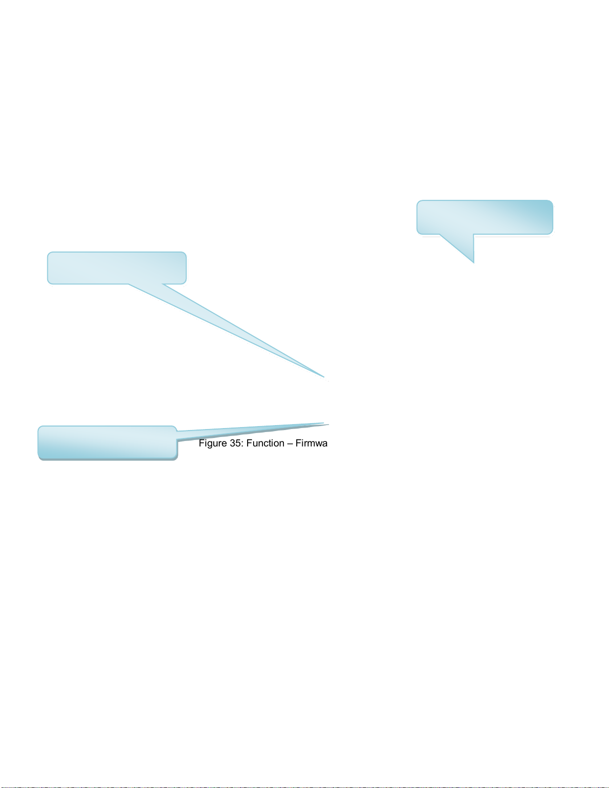
Step 1: Click to select the
file for upgrading.
Step 2: Click to finish the
software upgrading.
Click to swap the firmware
to the previous version
Firmware
There are two functions on the [Firmware] bar: [upgrade] and [swap]. [Upgrade] is used to upgrade software,
and [Swap] is to replace the current firmware version with the previous one.
Follow the steps shown below figure to upgrade the firmware.
Figure 35: Function – Firmware Upgrade
Log
Figure 36: Function – Log
Page 40

INSTALLATION GUIDE FOR RH-7W22
ENU STATUS : 1-0-0
Copyright - refer to title page
Page 40
Click to select the desired
Click to select the desired
Note: Click Create to create the report (the report can’t be created in IE browser) and make sure that PDF
Reader software is installed on the computer. If not, the report will not be visible.
Dry Contact
parameters for dry contact 1-6
License
Figure 37: Function – Alarm Setting
Figure 38: Function – License
parameters for Ext Alarm 1-4
Page 41

INSTALLATION GUIDE FOR RH-7W22
ENU STATUS : 1-0-0
Copyright - refer to title page
Page 41
For the CriticalPoint DAS, users are able to switch the configuration anytime by changing the license in the
WEBOMT. There are 3 difference licenses: 700MHz single band license, 800MHz single band license and
700MHz/800MHz dual band license.
Both 700MHz and 800MHz single band licenses are provided with a single band unit. Users can switch
between 700MHz configuration and 800MHz configuration. To upgrade from single band to dual band, users
need to purchase the dual band upgrade license.
If the equipment is in dual band originally, no license will be provided, because the equipment already comes
with dual band activated.
For more information please refer to appendix B for the license switch guide.
5.2.3 [TOPOLOGY][PROGRAM INFO]
This page is for factory setting only.
5.2.4 [AUTO SETUP]
To complete the installation and commissioning, users need to follow the steps below.
Step 1: Click the Menu bar [Auto Setup] on home screen, a work flow will be displayed.
Figure 39: Program Information
Page 42

INSTALLATION GUIDE FOR RH-7W22
ENU STATUS : 1-0-0
Copyright - refer to title page
Page 42
Figure 40: Commissioning Procedure – Start
Step 2: Click [Start] to start the process.
Page 43

INSTALLATION GUIDE FOR RH-7W22
ENU STATUS : 1-0-0
Copyright - refer to title page
Page 43
Figure 41: Commissioning Procedure – Scan
NOTE: Make sure the device is connected with appropriate donor and service antennas before
proceeding to step 3.
Step 3: Click [Next] to enter to Isolation Detection Screen.
Page 44

INSTALLATION GUIDE FOR RH-7W22
ENU STATUS : 1-0-0
Copyright - refer to title page
Page 44
Figure 42: Commissioning Procedure – Isolation Detection
Step 4: Click [Next] to set the site information.
Page 45

INSTALLATION GUIDE FOR RH-7W22
ENU STATUS : 1-0-0
Copyright - refer to title page
Page 45
Figure 43: Device Information Setting
It is mainly used to record device location and Date/Time provides a time reference. Clicking the Config Value
of Date/Time will update the Date/Time automatically.
Step 5: Click [MU Setup] to MU parameter setting.
Page 46

INSTALLATION GUIDE FOR RH-7W22
ENU STATUS : 1-0-0
Copyright - refer to title page
Page 46
Figure 44: MU Parameter Setting
Step 6: Click [Next] to RU parameter setting.
Figure 45: RU Parameter Setting
Page 47

INSTALLATION GUIDE FOR RH-7W22
ENU STATUS : 1-0-0
Copyright - refer to title page
Page 47
Step 7: Select [Finish] and click [OK] to finish commissioning.
Figure 46: Finish
5.2.5 [SYSTEM]
Inport&Export
Figure 47: System – Import & Export
Here can be imported / exported both MU and RU parameters.
The parameters that can be imported / exported include sub band, alarm enable, ATT value, RF switch, and DL
output power.
Page 48

INSTALLATION GUIDE FOR RH-7W22
ENU STATUS : 1-0-0
Copyright - refer to title page
Page 48
Summary
Figure 48: System – Summary
Here can create both MU and RU summary report.
The device basic information, an overview of RF information and sub-band RF information are included in this
report.
Scan
Figure 49: System – Scan
Here can scan the all the system equipment quantities.
Reset
Figure 50: System – Remove
Page 49

INSTALLATION GUIDE FOR RH-7W22
ENU STATUS : 1-0-0
Copyright - refer to title page
Page 49
Here can remove RUs.
Firmware
Figure 51: System – Firmware
Here can upgrade both MU and RU firmware, and swap them.
Log
Figure 52: System – Log
Here can export both MU and RU log report.
Isolation
Figure 53: System – Isolation
Page 50

INSTALLATION GUIDE FOR RH-7W22
ENU STATUS : 1-0-0
Copyright - refer to title page
Page 50
Here can check different RUs isolation.
End of Section
Page 51

INSTALLATION GUIDE FOR RH-7W22
ENU STATUS : 1-0-0
Copyright - refer to title page
Page 51
6 MAINTENANCE
The PS DAS is designed for trouble-free operation and generally does not need maintenance. Maintenance
activities should only be carried out by trained personnel.
Periodic inspection of the repeater equipment(s) is recommended, the recommended tasks includes:
Verify the direction and position of antennas. Re-align if necessary.
Make sure the cable connector and sealing on the RF cable connectors are not damaged.
Verify lightning and grounding protection is in good condition.
End of Section
Page 52

INSTALLATION GUIDE FOR RH-7W22
ENU STATUS : 1-0-0
Copyright - refer to title page
Page 52
7 APPENDICES
7.1 APPENDIX A: TOOLS
The following are the recommended list of tools for new installation and routine maintenance.
Slotted Screwdriver
Philips Screwdriver
Ring Spanner (Assorted size: 12~20mm)
Electrically operated drill and masonry drill bits 12mm
Anti-static Wrist Strap
Side Cutter
Frequency Counter (e.g. FLUKE PM6685R)
RF Power Meter (e.g. Bird 5000)
Page 53
INSTALLATION GUIDE FOR RH-7W22
ENU STATUS : 1-0-0
Copyright - refer to title page
Page 53
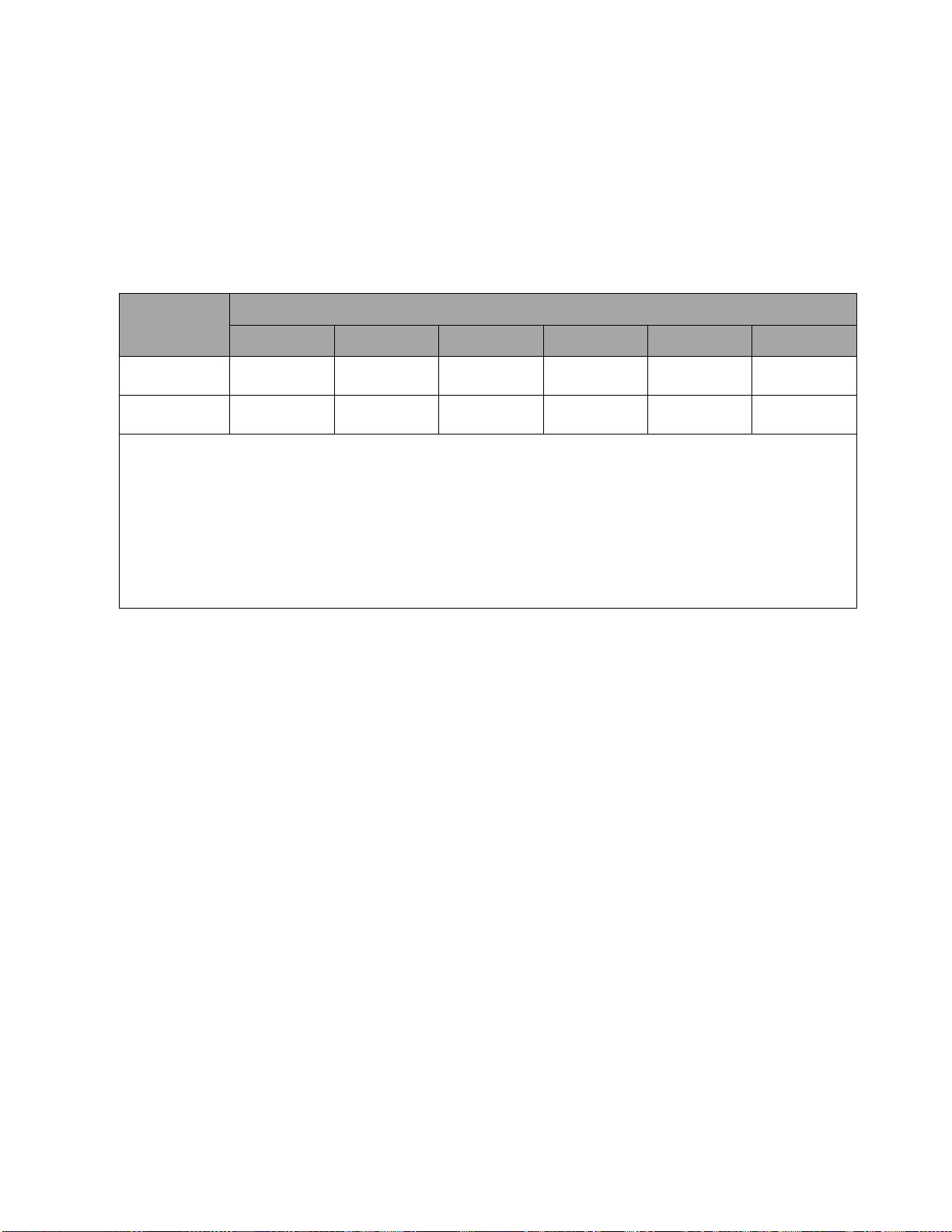
Part Name
Harmful Substance
Pb
Hg
Cd
Cr (VI)
PBB
PBDE
A
× ○ ○ ○ ○
○
B
× ○ ○ ○ ○
○
Note: Above table complies with SJ/T 11364.
○: Indicates that the harmful substance content in all homogeneous materials for corresponding part is under the limited
requirement of GB/T 26572.
×: Indicates that the harmful substance content in at least one single homogeneous material for the corresponding part exceeds the
limited requirement of GB/T 26572.
Remark: The content of the parts marked with “×”above exceeds the requirement as there is still no mature alternative
technologies to achieve the replacement of poisonous and harmful materials or elements.
7.2 APPENDIX B: DECLARATION OF HARMFUL SUBSTANCES AND
CONTENT
Product Name: Public Safety BDA
Model: RX-7W22
Harmful substance and content of this product as below table shown:
Page 54

INSTALLATION GUIDE FOR RH-7W22
ENU STATUS : 1-0-0
Copyright - refer to title page
Page 54
7.3 APPENDIX C: LICENSE SWITCH QUICK GUIDE
For CriticalPoint DAS, users are able to switch the configuration anytime by changing the license in the
WEBOMT. There are 3 difference licenses: 700MHz single band license, 800MHz single band license and
700MHz/800MHz dual band license.
Both 700MHz and 800MHz single band licenses are provided with a single band unit. Users can switch
between 700MHz configuration and 800MHz configuration. To upgrade from single band to dual band
configurations, users need to purchase the dual band upgrade license..
If the equipment is in dual band originally, no license will be provided, because the equipment already comes
with dual band activated.
Please follow the steps to switch configuration by license:
Step 1: Connect the unit “OMT port” to a laptop with an Ethernet cable.
Step 2: Wait approximately 1 minute until the IP address is established. Open the browser (Firefox is
recommended), login to WEBGUI with: www.combaomt.com or 192.168.8.101.
Step 3: Input User Name: admin; Password: (default: admin). Click [Log in].
Figure 54: Input User Name and Password
Page 55

INSTALLATION GUIDE FOR RH-7W22
ENU STATUS : 1-0-0
Copyright - refer to title page
Page 55
Enter the
Step 4: Go to Function -> License as shown in figure blow. Input the license code in the License field and click
submit to continue. The license code is presented as a label on the equipment.
license code
here and click
Figure 55: Input License Code
Step 5: Refresh the page from the browser, and if the Dev Authorization Status shows the specific band is
authorized, it means the license switch was successful.
Figure 56: License switch success
Page 56

INSTALLATION GUIDE FOR RH-7W22
ENU STATUS : 1-0-0
Copyright - refer to title page
Page 56
7.4 APPENDIX D: RMA (RETURN MATERIAL AUTHORIZATION)
End of Section
End of Document
Page 57

INSTALLATION GUIDE FOR RH-7W22
ENU STATUS : 1-0-0
Copyright - refer to title page
Page 57
 Loading...