

Page 1

INSTALLATION GUIDE FOR RA-8000
RA-8000 QI Copyright - refer to title page Page 1
ENU Status : 1-0-0
RA-8000
800MHZ FIBER OPTIC REPEATER
The information contained herein is the
responsibility of and is approved by the
following, to whom all enquiries should
be directed in the first instance:
Comba Telecom Ltd.
This is an unpublished work the copyright in which vests in Comba International ("Comba"). All rights reserved.
The information contained herein is confidential and the property of Comba and is supplied without liability for errors or
omissions. No part may be reproduced, disclosed or used except as authorized by contract or other written permission. The
copyright and the foregoing restriction on reproduction and use extend to all media in which the information may be embodied.
USER MANUAL
Page 2

INSTALLATION GUIDE FOR RA-8000
RA-8000 QI Copyright - refer to title page Page 2
ENU Status : 1-0-0
0.2 CONTENTS
Section Page
0.2 CONTENTS...........................................................................................................................2
0.3 INDEX TO FIGURES AND TABLES ..................................................................................... 4
0.4 HISTORY............................................................................................................................... 6
0.5 GLOSSARY OF TERMS ....................................................................................................... 7
0.6 SAFETY NOTICES AND ADMONISHMENTS...................................................................... 8
1 GENERAL INFORMATION ................................................................................................... 9
2 EQUIPMENT DESCRIPTION.............................................................................................. 11
2.1 SYSTEM DIAGRAM ............................................................................................................ 11
2.2 TYPICAL APPLICATION.....................................................................................................12
2.3 EQUIPMENT LAYOUT........................................................................................................13
2.4 EQUIPMENT CONSTITUTION ........................................................................................... 15
2.5 KIT OF PARTS ....................................................................................................................16
3 INSTALLATION ................................................................................................................... 17
3.1 WARNINGS AND ALERTS ................................................................................................. 17
3.2 SITE PLANNING CONSIDERATIONS................................................................................ 18
3.2.1 REPEATER INSTALLATION CHECKLIST ......................................................................... 19
3.3 INSTALLATION PROCEDURES ........................................................................................20
3.3.1 GOODS INWARDS INSPECTION ...................................................................................... 20
3.3.2 TOOLS.................................................................................................................................20
3.3.3 PREPARATION...................................................................................................................20
3.3.4 RACK MOUNTING OF MOU .............................................................................................. 21
3.3.5 MOUNTING ARRANGEMENT............................................................................................22
3.3.6 RRU LIFTING LUG.............................................................................................................. 23
3.3.7 WALL MOUNTING OF RRU MOUNTING RACK ...............................................................23
3.3.8 POLE MOUNTING OF RRU MOUNTING RACK................................................................ 24
3.3.9 ATTACHING RRU ONTO MOUNTING RACK.................................................................... 25
3.3.10 DRIP-LOOP.........................................................................................................................25
3.4 EQUIPMENT CONNECTORS ............................................................................................26
3.4.1 MOU CONNECTORS.......................................................................................................... 26
3.4.2 RRU CONNECTORS .......................................................................................................... 31
3.5 EQUIPMENT CONNECTION..............................................................................................32
3.5.1 GROUNDING CONNECTION.............................................................................................32
3.5.2 SERVICE VOLTAGE CONNECTION .................................................................................32
3.5.3 LI-ION BATTERY CONNECTION ....................................................................................... 33
3.5.4 RF CONNECTION............................................................................................................... 33
3.5.5 OPTICAL CONNECTION.................................................................................................... 34
3.5.6 EXTERNAL ALARM CONNECTION...................................................................................34
3.5.7 BTS ALARM CONNECTION............................................................................................... 35
3.5.8 MOU SHELF INTERNAL CONNECTION ...........................................................................36
3.5.9 INTEGRATED MODEM CONNECTON .............................................................................. 37
3.5.10 CONNECT TO PC...............................................................................................................39
4 COMMISSIONING............................................................................................................... 40
4.1 PRE-COMMISSIONING TASKS ......................................................................................... 40
4.2 LED INDICATORS ..............................................................................................................40
4.2.1 MCU LED INDICATORS ..................................................................................................... 40
4.2.2 RRU LED INDICATORS......................................................................................................40
4.3 OMT.....................................................................................................................................41
4.3.1 LOCAL AND REMOTE CONNECTIONS TO OMT.............................................................41
4.3.2 LOCAL CONNECTION TO OMT ........................................................................................41
Page 3

INSTALLATION GUIDE FOR RA-8000
RA-8000 QI Copyright - refer to title page Page 3
ENU Status : 1-0-0
4.3.3
REMOTE CONNECTION TO OMT.....................................................................................42
4.3.4 OMT CONFIGURATION .....................................................................................................43
4.3.5 SYSTEM INFO ....................................................................................................................43
4.3.6 RF PARAMETER ................................................................................................................44
4.3.7 SWITCH...............................................................................................................................44
4.3.8 ATT ...................................................................................................................................... 44
4.3.9 ALARM THRESHOLD ......................................................................................................... 45
4.3.10 ALARM INFORMATION ...................................................................................................... 45
4.3.11 PROPERTIES INFORMATION ........................................................................................... 47
4.3.12 EQUIPMENT ID................................................................................................................... 47
4.3.13 COMM. CONFIG .................................................................................................................48
4.3.14 DATA MAINTENANCE........................................................................................................50
4.4 NON-VOLATILE MEMORY.................................................................................................50
4.5 COMMISSIONING PROCEDURES .................................................................................... 51
5 MAINTENANCE ..................................................................................................................52
5.1 O-RING FITTING DETAILS................................................................................................. 52
6 APPENDICES......................................................................................................................53
6.1 APPENDIX A: TOOLS FOR INSTALLATION AND MAINTENANCE ................................. 53
6.2 APPENDIX B: SERVICING POLICY AND RETURN OF EQUIPMENT .............................54
6.3 APPENDIX C: RMA (RETURN MATERIAL AUTHORIZATION) FORM.............................55
Page 4

INSTALLATION GUIDE FOR RA-8000
RA-8000 QI Copyright - refer to title page Page 4
ENU Status : 1-0-0
0.3 INDEX TO FIGURES AND TABLES
Figure 1: View of MOU Fully Equipped Shelf .......................................................................................10
Figure 2: Front, Side and Bottom Views of RRU Enclosure.................................................................10
Figure 3: MOU System Diagram...........................................................................................................11
Figure 4: RRU System Diagram ...........................................................................................................11
Figure 5: Application of one MOU with one RRU through Single Channel FOU with Internal WDM...12
Figure 6: Application of one MOU with two RRUs through Dual Channel FOU with Internal WDM ....12
Figure 7: Fully Equipped Front View of MOU .......................................................................................13
Figure 8: RRU Equipment Layout.........................................................................................................14
Figure 9: Rack Mounting of 19” Shelf ...................................................................................................21
Figure 10: RRU Mounting Rack Dimension..........................................................................................22
Figure 11: RRU Enclosure Lifting Lug Attachment Details...................................................................23
Figure 12: RRU Mounting Rack Wall Mounting....................................................................................23
Figure 13: Pole Mounting of RRU Mounting Rack................................................................................24
Figure 14: Attaching the RRU onto the Mounting Rack........................................................................25
Figure 15: MOU Back Panel View ........................................................................................................30
Figure 16: RRU Connectors..................................................................................................................31
Figure 17: Pins Allocation for “EXT_ALM” Port ....................................................................................34
Figure 18: Pin Allocation for “BTS_ALM” Port......................................................................................35
Figure 19: RF Connection between RFU and Single Output in FOU1.................................................36
Figure 20: RF Connection between RFU and Two Outputs in FOU1 ..................................................36
Figure 21: RF Connection between RFU and Two Outputs in FOU1, One Output in FOU2...............37
Figure 22: RF Connection between RFU and Two Outputs in FOU1, Two Outputs in FOU2 .............37
Figure 23: Wireless Modem..................................................................................................................37
Figure 24: Diagram of wireline modem.................................................................................................38
Figure 25: Location of RRU LED Indicators..........................................................................................41
Figure 26: Connection Type..................................................................................................................42
Figure 27: Serial Port Configuration......................................................................................................42
Figure 28: Remote Connection.............................................................................................................42
Figure 29: OMT Main Window..............................................................................................................43
Figure 30: System Information..............................................................................................................43
Figure 31: RRU Switch .........................................................................................................................44
Figure 32: MOU ATT.............................................................................................................................44
Figure 33: MOU Alarm Threshold.........................................................................................................45
Figure 34: RRU Alarm Threshold..........................................................................................................45
Figure 35: MOU Master Alarm..............................................................................................................46
Figure 36: MOU Channel Alarm............................................................................................................46
Figure 37: RRU Master Alarm...............................................................................................................46
Figure 38: RRU External Alarm ............................................................................................................47
Figure 39: MOU Equipment ID..............................................................................................................48
Figure 40: ROU Equipment ID..............................................................................................................48
Figure 41: MOU Comm.Config .............................................................................................................49
Figure 42: “O” ring fitting details............................................................................................................52
Table 1: MOU Shelf Equipping Rule.....................................................................................................13
Table 2: RA-8000 Regular KOP............................................................................................................16
Table 3: MOU KOP...............................................................................................................................16
Table 4: RRU KOP................................................................................................................................16
Table 5: Repeater Installation Checklist...............................................................................................19
Table 6: PSU SIU Description...............................................................................................................27
Table 7: MCU SIU Description..............................................................................................................28
Table 8: Single Channel FOU SIU Description.....................................................................................29
Table 9: Dual Channel FOU SIU Description .......................................................................................29
Table 10: MOU Back Panel Connectors...............................................................................................30
Table 11: RRU connectors....................................................................................................................31
Table 12: Pin Definition of “EXT_ALM” Port .........................................................................................34
Table 13: Voltage Applied to EXT_ Alarm1~4......................................................................................34
Table 14: Pin definition of the BTS_ALM port.......................................................................................35
Page 5

INSTALLATION GUIDE FOR RA-8000
RA-8000 QI Copyright - refer to title page Page 5
ENU Status : 1-0-0
Table 15: MCU LED Indicators.............................................................................................................40
Table 16: RRU LED Indicators..............................................................................................................40
Table 17: Equipment ID ........................................................................................................................47
Table 18: Comm.Config........................................................................................................................49
Page 6

INSTALLATION GUIDE FOR RA-8000
RA-8000 QI Copyright - refer to title page Page 6
ENU Status : 1-0-0
0.4 HISTORY
Change No. ENU Details Of Change
1 1-0-0 This document first created in July 2010.
Page 7

INSTALLATION GUIDE FOR RA-8000
RA-8000 QI Copyright - refer to title page Page 7
ENU Status : 1-0-0
0.5 GLOSSARY OF TERMS
ALC
Automatic Level Control
ATT Attenuation
BS Base Station
BTS Base Transceiver Station
dB Decibel
dBm Decibels relative to 1 milliwatt
DL Downlink
DPX Duplexer
DT Donor Terminal
EEPROM Electrically Erasable Programmable Read Only Memory
E/O,O/E Electrical/Optical, Optical/Electrical
Hz Hertz
ID Identification
LNA Low Noise Amplifier
MCU Main Control Unit
MHz Megahertz
MT Mobile Terminal
MTBF Mean Time Between Failures
NC Normally Closed
NF Noise Figure
NO Normally Open
OMC Operation & Maintenance Center
OMT Operation & Maintenance Terminal
OP Optical Fiber
PA Power Amplifier
PLL Phase Locked Loop
PSU Power Supply Unit
RF Radio Frequency
RX Receive
SMA Sub-Miniature “A” Connector
TETRA Terrestrial Trunked Radio
TX/RX Transmit/Receive
UL Uplink
VAC Volts Alternating Current
VSWR Voltage Standing Wave Ratio
WCDMA Wideband Code Division Multiple Access
WDM Wavelength Division Multiplexer
Page 8

INSTALLATION GUIDE FOR RA-8000
RA-8000 QI Copyright - refer to title page Page 8
ENU Status : 1-0-0
0.6 SAFETY NOTICES AND ADMONISHMENTS
This document contains safety notices in accordance with appropriate standards. In the interests of
conformity with the territory standards for the country concerned, the equivalent territorial
admonishments are also shown.
Any installation, adjustment, maintenance and repair of the equipment must only be carried out by
trained, authorized personnel. At all times, personnel must comply with any safety notices and
instructions.
Specific hazards are indicated by symbol labels on or near the affected parts of the equipment. The
labels conform to international standards, are triangular in shape, and are colored black on a yellow
background. An informative text label may accompany the symbol label.
Hazard labeling is supplemented by safety notices in the appropriate equipment manual. These
notices contain additional information on the nature of the hazard and may also specify precautions.
Warning:
These draw the attention of personnel to hazards which may cause death or injury to the operator or
others. Examples of use are cases of high voltage, laser emission, toxic substances, point of high
temperature, etc.
Alert:
These draw the attention of personnel to hazards which may cause damage to the equipment. An
example of use is the case of static electricity hazard.
Caution notices may also be used in the handbook to draw attention to matters that do not constitute
a risk of causing damage to the equipment but where there is a possibility of seriously impairing its
performance, e.g. by mishandling or gross maladjustment. Warnings and Cautions within the main
text do not incorporate labels and may be in shortened form.
End of section
Page 9

INSTALLATION GUIDE FOR RA-8000
RA-8000 QI Copyright - refer to title page Page 9
ENU Status : 1-0-0
1 GENERAL INFORMATION
RA-8000 800MHz Fiber Optic Repeater (hereinafter called system) is designed for the flexible
enhancement of BTS signal, the elimination of blind area for cell coverage and the optimization for
network coverage. It improves UL/DL signals for better voice quality after amplification, thus extends
the BTS signals coverage.
This system consists of Direct Coupling Master Optical Unit (MOU) RA-8000-D, Remote Radio Unit
(RRU) RA-8000-R.
This system can achieve the complete backup for the entire communication link through hot stand-by
RF modules. With lower cost but desirable performance, this system is suitable for digital trunking
network applications as traffic, government, subways, etc.
Remote configuration and surveillance is possible through Comba’s OMT/OMC.
Characteristics of the RA-8000 system are as follows:
y Optimization for 800MHz band.
y High dependable performance with the competent solution of hot stand-by RF modules.
y High output power with high linearity power amplifier, which ensures the signal source is of good
quality.
y Integrated alarm interface for remote system monitoring.
y Local Operation and Maintenance Terminal (OMT): Operating status and parameters can be set
or monitored locally by OMT PC. The point-to-point setting and inquiry between MOU and RRU
is realizable through the integrated FSK modem, which makes it convenient for on-site
configuration.
y Operation Maintenance Center (OMC): System working parameters and communication
configuration can be set or inquired remotely through the integrated wireline modem. If alarm is
generated, the equipment will dial up to OMC automatically, which will send short messages to
the handset of maintenance staff.
y Back-up Li-ion battery keeps the alarm unit running for up to two hours after power cut.
y The RRU enclosure is designed for all sheltered installation - waterproof, damp-proof and omni-
sealed (IP65).
Page 10
INSTALLATION GUIDE FOR RA-8000
RA-8000 QI Copyright - refer to title page Page 10
ENU Status : 1-0-0
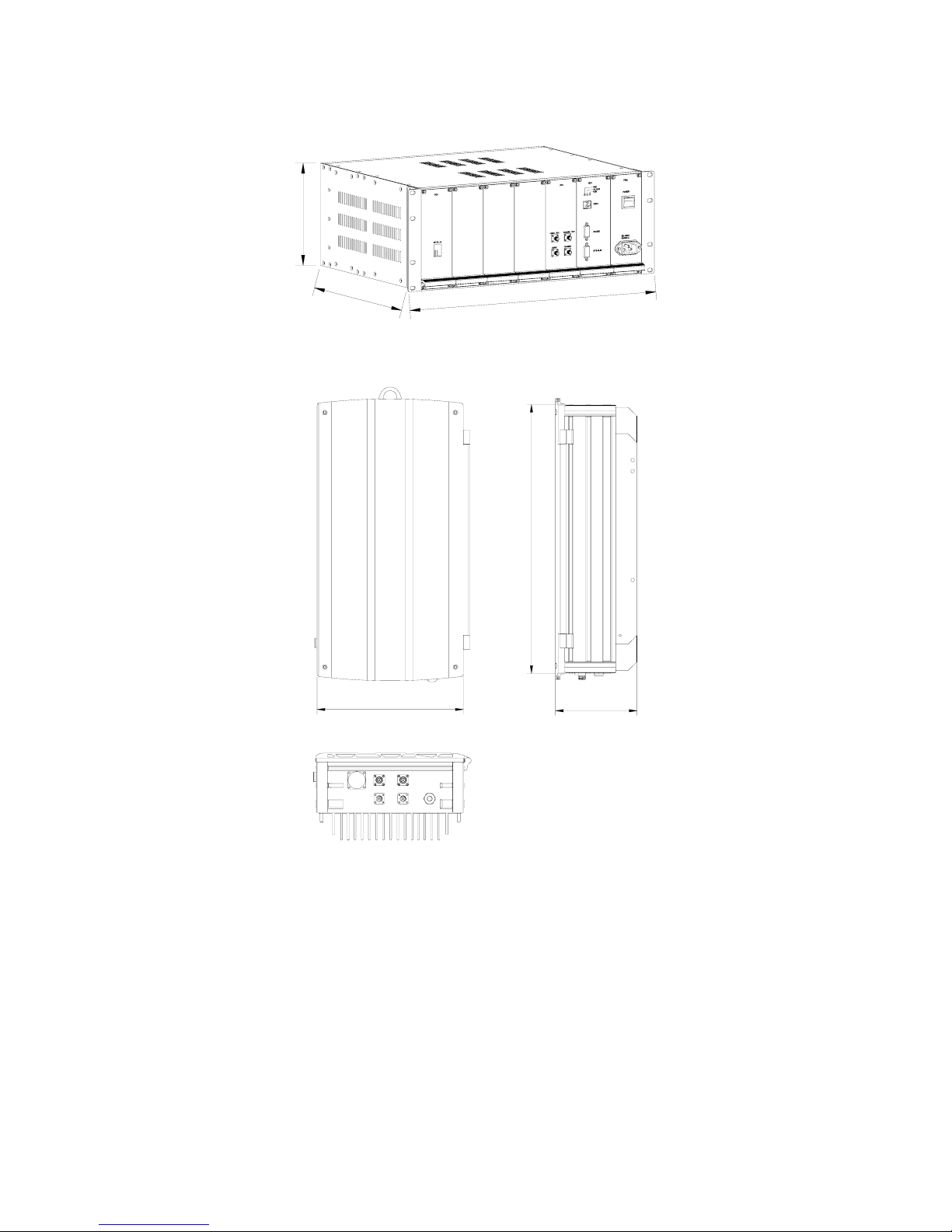
The figures below show the equipment enclosure layout of RA-8000 MOU and RRU:
177
4
8
2
3
6
0
Figure 1: View of MOU Fully Equipped Shelf
RXTX
EXT_ALM RS-232
OP/DL_UL
200-240V~ 50Hz/60Hz
615
210
350
Figure 2: Front, Side and Bottom Views of RRU Enclosure
Page 11
INSTALLATION GUIDE FOR RA-8000
RA-8000 QI Copyright - refer to title page Page 11
ENU Status : 1-0-0
2 EQUIPMENT DESCRIPTION
2.1 SYSTEM DIAGRAM
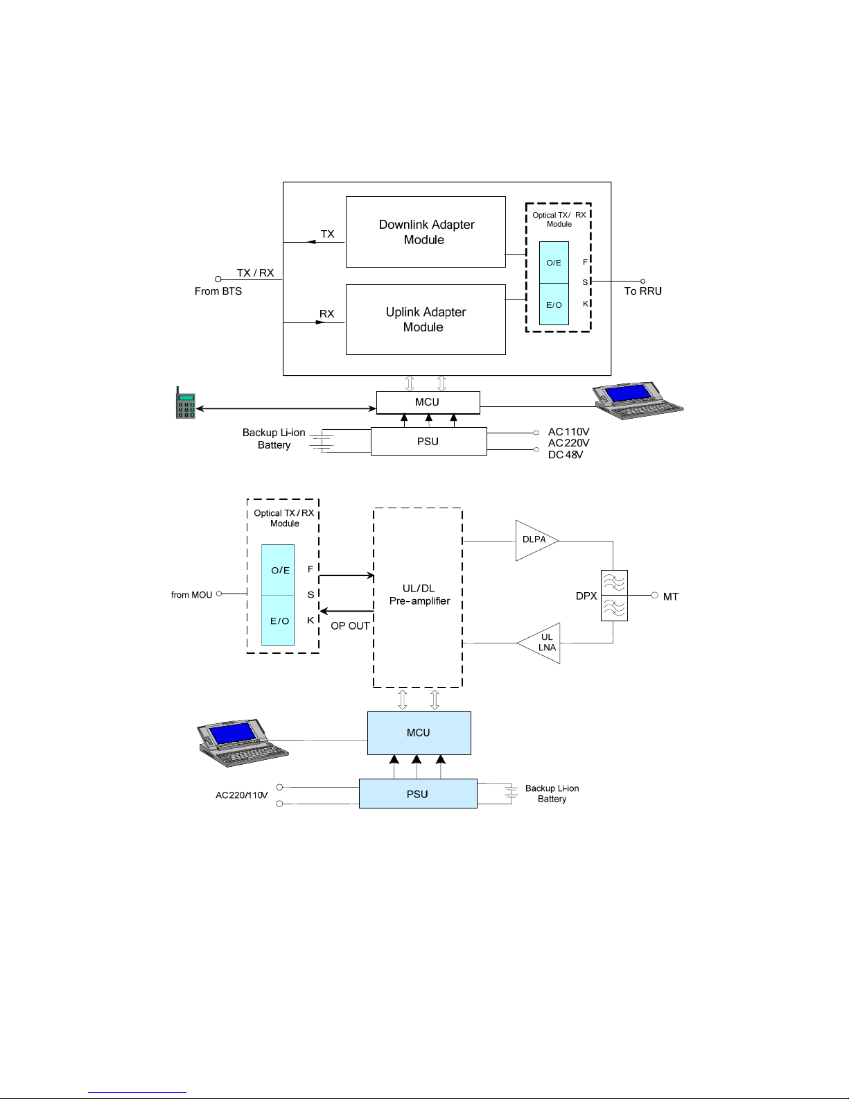
Figure 3: MOU System Diagram
Figure 4: RRU System Diagram
As shown in the above figures, the DL signals from the BTS are coupled directly and converted into
optical signals after amplification in the MOU. Then, the optical signals are transmitted to the RRU via
optical fiber. The Optical TX/RX Module of RRU converts the DL optical signals into RF signals. After
amplification, the signals are transmitted at the MT port to the service antenna.
On the UL, the signals transmitted by the mobile are converted into optical signals, and then via the
UL optical fiber. The signals are transmitted to MOU, which then converts the optical signals back to
RF signals. After amplification, the signals are transmitted back to the BTS.
Communication over optical fiber allows the RRU to be managed with the same fiber connection to
the MOU. This is achieved by using the integrated Frequency Shift Keying (FSK) modem.
Page 12
INSTALLATION GUIDE FOR RA-8000
RA-8000 QI Copyright - refer to title page Page 12
ENU Status : 1-0-0
2.2 TYPICAL APPLICATION
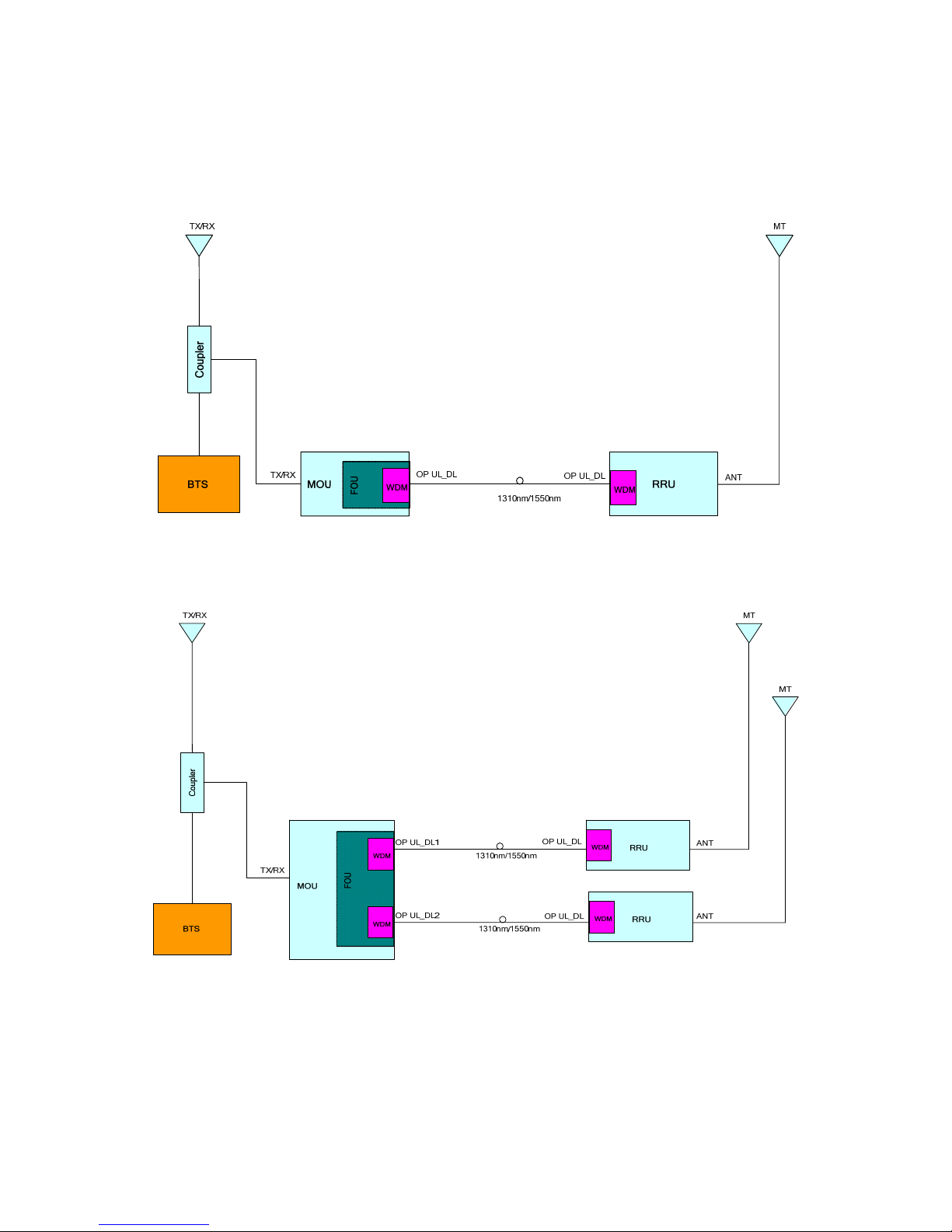
The standard configuration is one MOU connects with one RRU through Single Channel FOU.
Figure 5: Application of one MOU with one RRU through Single Channel FOU with Internal WDM
A fully equipped Master Optical Unit can accommodate two Double Channel FOUs. A fully equipped
MOU can host two RRUs.
Figure 6: Application of one MOU with two RRUs through Dual Channel FOU with Internal WDM
Page 13
INSTALLATION GUIDE FOR RA-8000
RA-8000 QI Copyright - refer to title page Page 13
ENU Status : 1-0-0
2.3 EQUIPMENT LAYOUT
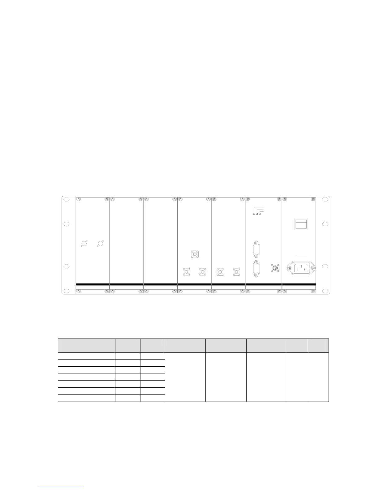
The RA-8000 MOU (RA-8000-M) is constructed into a 19” 4U shelf, with connectors located on the
front and back panels. The RRU (RA-8000-R) is designed for all cables entries from the bottom of the
enclosure.
The MOU consists of a shelf that accommodates up to seven slide-in modules. Slots are numbered
‘1’ to ‘7’ from left to right. The following slide-in modules are accommodated with the MOU:
y Fiber Optical Unit (FOU)
y Radio Frequency Unit (RFU)
y Main Control Unit (MCU)
y Power Supply Unit (PSU)
All the slide-in modules except the MCU are designed with a backup module being exist concurrently.
This ensures the dependable operation of the entire system due to fault of any module.
For illustration purposes, shown below are two variants of Fiber Optical Unit (FOU) for standard and
extension configuration. From left to right, they are: Single Channel FOU, Dual Channel FOU. Where
applicable, blanking off plates and SMA-SMA jumpers are supplied
OP/UL-DL
POWER
PSU
RFU
MCU
FSK
ALARM
PUN
BTS-ALM
RS-232
OP/UL-DL
FOU
50/60Hz
220~240V
Modem
RFU
TX/RX
Downlink
Uplink
Downlink
Uplink
Figure 7: Fully Equipped Front View of MOU
Depending on customer’s network requirement of whether it is Single Channel FOU or Double
Channel FOU been integrated, two kinds of equipment layout of MOU shelf exist. Shown below is the
equipping rule of the MOU shelf.
Solution and SIU
equipping
Slot 1 Slot 2 Slot 3 Slot 4 Slot 5 Slot 6 Slot
7
4x RRU Solution 2 2
3x RRU Solution 2 1
3x RRU Solution 1 2
2x RRU Solution 2
Blank
2x RRU Solution
Blank
2
1x RRU Solution 1
Blank
1x RRU Solution Blank
1
Blank
Blank
RFU
MCU PSU
Table 1: MOU Shelf Equipping Rule
• ‘1’ denotes Single Channel FOU (with or without Integrated WDM capability)
• ‘2’ denotes Dual Channel FOU (either with or without Integrated WDM capability). By design,
only slot ‘1’ and ‘2’ can accommodate Dual Channel FOU
Page 14
INSTALLATION GUIDE FOR RA-8000
RA-8000 QI Copyright - refer to title page Page 14
ENU Status : 1-0-0
• “Blank” denotes position for “Blanking off plate” this slot may be interchanged with Single
Channel FOU
• RFU by design is equipped in Slot 5, MCU by design is equipped in Slot 6, PSU by design is
equipped in slot 7
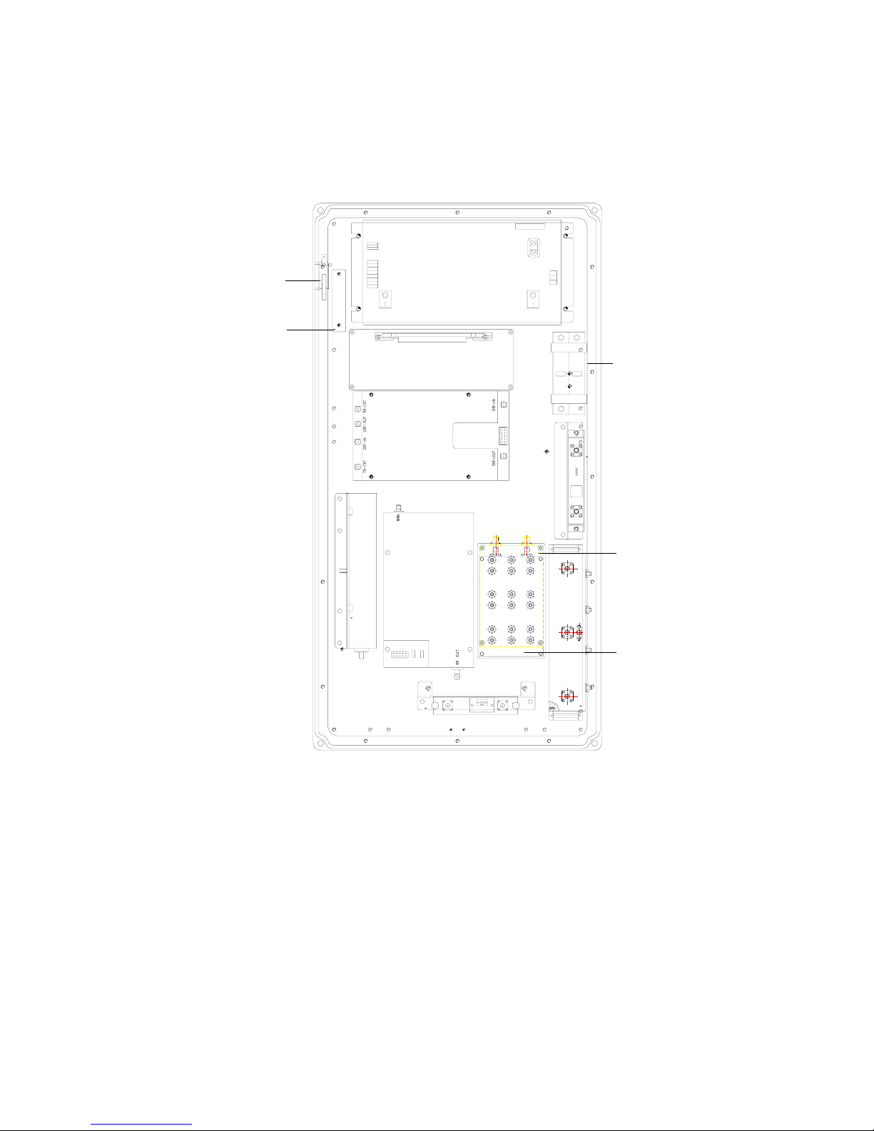
The internal layout for the RRU is shown below:
V20-C V20-C
POWER
MODEL:
S/N NO.:
28V+
IN OK
BAT2+
GND
L
E
N
BAT2
AC
Output
28V-
9V+
9V-
JK+
JK-
BAT2-
OUT OK
RF OUT
RF IN
PA
Pre-amplifier
MCU
Distribution Board
PSU
Optical TX/RX
Module
VSWR Module
LNA
DPX
Li-ion Battery
Door Open Switch
Surge Arrestor
UL Filter
DL Filter
Figure 8: RRU Equipment Layout
Page 15

INSTALLATION GUIDE FOR RA-8000
RA-8000 QI Copyright - refer to title page Page 15
ENU Status : 1-0-0
2.4 EQUIPMENT CONSTITUTION
This RA-8000 system consists of MOU and RRU that consist of the modules described below:
MOU Modules
• Radio Frequency Unit (RFU): RF connection with the FOU(s) is from the rear panel, whereas BTS
RF connection(s) are connected to the front.
• Power Supply Unit (PSU): Converts the input voltage into a stable DC to provide power for other
modules and to charge the internal Li-ion battery. The integrated Li-ion battery provides power to
the Main Control Unit to send alarm signals in the event of power failure.
• Main Control Unit (MCU): Controls and monitors the operation parameters of the MOU and
provides communication interface for local monitoring and remote monitoring.
• Fiber Optical Unit (FOU): Interface between MOU and RRUs. Performs conversion between RF
and optical signals. It consists of an FSK modem for communication between the MOU and RRU
over optical fiber.
RRU Modules
• Main Control Unit (MCU): Controls and monitors the operation parameters of the RRU and
provides communication interface for local monitoring.
• Optical TX/RX Module: Performs conversion between optical and RF signals and the gain setting
of fiber link. Optical RX Module converts the received optical signals into RF signals and the
Optical TX Module converts the received RF signals into optical signals to be transmitted back to
the MOU.
• Duplexer (DPX): TX/RX the uplink and downlink signals.
• Pre-amplifier Module: Pre-amplifies the RF signals from/to the Optical TX/RX Module.
• Power Supply Unit (PSU): Converts the input AC voltage into a stable DC to provide power for
other modules and to charge the internal Li-ion battery. Two switches exist on the PSU when
viewing from the front of the PSU, “Left” switch controls power to the RRU, and the “Right” switch
control the circuit between the Li-ion battery pack and the MCU.
• Surge Arrestor: Provides protection to the PSU.
• Low Noise Amplifier (LNA): with ATT function, used to pre-amplify the signal in and Uplink to
ensure low noise.
• Li-ion Battery: Supplies power to alarm unit for up to two hours in the event of AC/DC power
failure.
• UL/DL filter: The use of filter can select and purify the desired signals.
• Door Open Switch: Used to monitor the door status. If the door is open, a door open alarm will be
generated.
• VSWR Module: Used to test the VSWR of UL output and input to MT. A VSWR alarm will be
generated, if the tested VSWR is over the threshold.
• Distribution Board: The distribution board serves as a distributor for power and internal
communication within the equipment. It provides connectivity to function modules, MCU and
RS232 port for local control.
Page 16

INSTALLATION GUIDE FOR RA-8000
RA-8000 QI Copyright - refer to title page Page 16
ENU Status : 1-0-0
2.5 KIT OF PARTS
For this system, the following are shipped:
Table 2: RA-8000 Regular KOP
Product Identifier Description Quantity
250V/3.2A Delay Fuse Equipment replacement fuse 2
Power supply cable n/a 1
R-9122C/R-9122AC Commissioning Cable 1
XD-GSM-900/1800V-3 Antenna for modem 1
Table 3: MOU KOP
Product Identifier Description Quantity
T3-099901-5201 Mounting Rack 1
T3-000201-5114 Lifting Lug 1
T3-099901-5202 Clamp 2
00-100DJT5104 Optical Connector Cover 1
00-100DJT-5105 Optical Connector Screw Cap 1
00-100DJT-5106 Rubber Loop 1
n/a Enclosure Key for door-lock 2
M10xM110 Masonry bolts 4
M12x160 Carriage Bolt set 4
M6 x12 Hex Socket Bolt 2
M8 x20 Hex Socket Bolt 6
M12 Nut 8
M6 Spring Washer 2
5.5mm Allen Key 1
X14J5-DB9K
Commissioning cable for local
commissioning
1
Delay Fuse Equipment replacement fuse 2
Table 4: RRU KOP
End of Section
Product Identifier Description Quantity
RA-8000 QI This equipment manual 1
OMT V4.0 or above OMT software on CD-Rom 1
n/a Testing Report 1
Page 17

INSTALLATION GUIDE FOR RA-8000
RA-8000 QI Copyright - refer to title page Page 17
ENU Status : 1-0-0
3 INSTALLATION
3.1 WARNINGS AND ALERTS
Laser
Laser light can cause damage to eyes. Laser light is not visible. Viewing it directly does not cause
pain. The iris of the eye will not close when viewing a bright light. Consequently, serious damage to
the retina of the eye is possible. NEVER LOOK INTO THE END OF A FIBER WHICH MAY HAVE A
LASER COUPLED TO IT.
Radio Frequency Energies
There may be situations, particularly for workplace environments near high-powered RF sources,
where recommended limits for safe exposure of human beings to RF energy could be exceeded. In
such cases, restrictive measures or actions may be necessary to ensure the safe use of RF energy.
High Voltage
The equipment has been designed and constructed to prevent, as far as reasonably, practicable
danger. Any work activity on or near equipment involving installation, operation or maintenance must
be, as far as reasonably, free from danger.
Where there is a risk of damage to electrical systems involving adverse weather, extreme
temperatures, wet, corrosive or dirty conditions, flammable or explosive atmospheres, the system
must be suitably installed to prevent danger.
Protective Earthing
Equipment provided for the purpose of protecting individuals from electrical risk must be suitable for
the purpose and properly maintained and used.
Handling Precautions
This covers a range of activities including lifting, lowering, pushing, pulling, carrying, moving, holding
or restraining an object, animal or person. It also covers activities that require the use of force or effort,
such as pulling a lever, or operating power tools.
Electrostatic Discharge (ESD)
Observe standard precautions for handling ESD-sensitive devices. Assume that all solid-state
electronic devices are ESD-sensitive. Ensure the use of a grounded wrist strap or equivalent while
working with ESD-sensitive devices. Transport, store, and handle ESD-sensitive devices in static-safe
environments.
Page 18

INSTALLATION GUIDE FOR RA-8000
RA-8000 QI Copyright - refer to title page Page 18
ENU Status : 1-0-0
3.2 SITE PLANNING CONSIDERATIONS
Site Considerations
The MOU can be located indoors to facilitate coupling of BTS signals and power supply connections.
The recommended input range of BTS signal is -15~5 dBm. Hence, an appropriate coupler must be
used according to input power of the repeater.
The RRU is designed to be waterproof, rainproof, and with snow protection. Temporary protection
should be taken when the equipment enclosure is opened for installation or maintenance in an
outdoor environment. The equipment must not be opened for installation or maintenance in bad
weather (e.g. gale, storm rainfall, extreme temperatures and high humidity)
The site considerations for RRUs are listed below:
• The distance between the service antenna of RRU and coverage area should satisfy line of sight
requirements for maximum coverage area.
• The maximum fiber length is 20km, with a maximum optical path loss of 10dB.
• For outdoor coverage applications, UL diversity is an option.
• The system delay of the optical system must be taken into consideration when there are
neighboring BTS sites overlapping in coverage.
Installation Location
Mounting surface shall be capable of supporting the weight of the equipment.
In order to avoid electromagnetic interference, a proper mounting location must be selected to
minimize interference from electromagnetic sources such as large electrical equipment.
Environmental
Humidity has an adverse effect on the reliability of the equipment. It is recommended to install the
equipment in locations having stable temperature and unrestricted air-flow.
The installation location for the product should be well ventilated. The equipment has been designed
to operate at the temperature range and humidity level as stated in the product specifications in the
datasheet.
Direct sun light exposure to the equipment should be avoided. Provide additional shelter if necessary.
Powering
The power supply unit (PSU) provides power to all modules within the equipment. Depending on the
product variant, it is recommended that the PSU operates on a dedicated circuit breaker or fused
circuit.
Grounding Requirement
Verify that the equipment has been well grounded. This includes antennas and all cables connected
to the system. Ensure lightning protection for the antennas is properly grounded.
Cable Routing
Depending on equipment configuration, a variety of types of cables are required. Where applicable,
ensure cables are properly routed and secured so that they are not damaged.
Manual Handling
During transportation and installation, take necessary handling precautions to avoid potential physical
injury to the installation personnel and the equipment.
Page 19

INSTALLATION GUIDE FOR RA-8000
RA-8000 QI Copyright - refer to title page Page 19
ENU Status : 1-0-0
3.2.1 REPEATER INSTALLATION CHECKLIST
Installation Location Requirement Considerations
Working Space available
Ample space on 19” rack and mounting pole/wall
surface (recommended to reserve 800mm x 800mm
x 800mm) for unrestricted airflow and cable routing.
AC Mains
Power cord length is about 3m. Use a
dedicated AC breaker or fuse circuit, and
with good access to an earthing point.
There are a number of power supply options
for MOU:
-48VDC
Power cord length is 3m with CSA of
2.5mm
2
Range: -36VDC to -72VDC.
The DC operating current should be
>10A.
RF ports terminated
Terminate all unused RF ports with the appropriate
terminating load
Earth point Earthing point/Safety ground within 2m / 6.5 ft.
EMC and interference
Do not locate near large transformers or motors that
may cause electromagnetic interference. Install
blanking off plates on the MOU.
Maintain distance from equipment to DT, MT
antennas
Reduce of signal loss in feeder cable
VSWR check For the antennas, VSWR value to be < 1.5
Suitable operating environment
-20°to +40°C for MOU and -33°to +55°C for RRU.
Maximum 85 % (MOU), 95 %( RRU) relative
humidity.
Locate BTS signal derived at the coupler.
Typical RF input signal from BTS is from -10dBm to
0dBm, select the correct coupler at the BTS site and
to tune the ATT for optimal RF performance.
Locate the mobile antenna according to the
coverage requirement.
Satisfying the requirement for Line of sight.
Confirm optical wavelength For fiber sharing or single fiber working
Confirm optical fiber availability
FC-FC connector < 20km between FOU and RRU.
With fiber path loss observed.
Optical fiber handling Maintain the minimum bending radius (> 30 mm)
Confirm RF cable availability For connection to BTS and to remote antenna.
Table 5: Repeater Installation Checklist
Page 20

INSTALLATION GUIDE FOR RA-8000
RA-8000 QI Copyright - refer to title page Page 20
ENU Status : 1-0-0
3.3 INSTALLATION PROCEDURES
3.3.1 GOODS INWARDS INSPECTION
This system was factory tested, inspected, packed, and delivered to the carrier with utmost care. Do
not accept shipment from carrier which shows damage or shortage until the carrier's agent endorses
a statement of the irregularity on the face of the carrier's receipt. Without documentary evidence, a
claim cannot be processed.
Open and check each package against the packing list. For any shortage, contact Comba Telecom
Systems. Do not remove items from packing materials until installation.
3.3.2 TOOLS
See appendix for a full list of tools required for installation and maintenance.
3.3.3 PREPARATION
• Mounting surface capable of support equipment’s weight: MOU at 12kg with RRU at 28kg
• Power outlet within 2m
• Terminate unused antenna/RF cable with 50 ohm terminator
• Protect unused optical interface with protective cap
• Earthing point/Safety ground within 2m
Antenna:
• Antenna installation is covered by their respective manuals. Take normal precautions when
preparing and handling feeder cables to ensure they are not damaged.
Optical Fiber:
• Fiber optic cables require proper handling. Do not stretch, puncture, or crush the fiber cable(s)
with staples, heavy equipment, doors, etc.
• Always maintain the minimum bending radius specified by the cable manufacturer. The minimum
bend radius is usually 10 times as the cable's outer diameter. In the case of single optical fiber
that is not in a cable, the minimum bending radius to be observed is 3cm.
Page 21
INSTALLATION GUIDE FOR RA-8000
RA-8000 QI Copyright - refer to title page Page 21
ENU Status : 1-0-0
3.3.4 RACK MOUNTING OF MOU
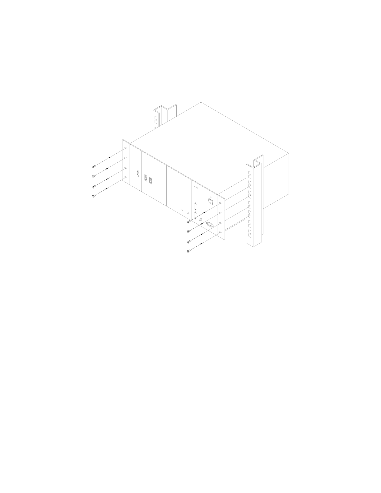
Depending on the installation, should 2-post open-rack are to be used, the mid-mounting brackets are
to be used. For rack or cabinet mounting, the mid-mounting brackets are to be removed from the 4U
shelf. Cage nut and screws are not supplied. Unless being recommended by rack manufacturer, M5
cage nut / bolt are to be used.
Figure 9: Rack Mounting of 19” Shelf
Page 22
INSTALLATION GUIDE FOR RA-8000
RA-8000 QI Copyright - refer to title page Page 22
ENU Status : 1-0-0
3.3.5 MOUNTING ARRANGEMENT
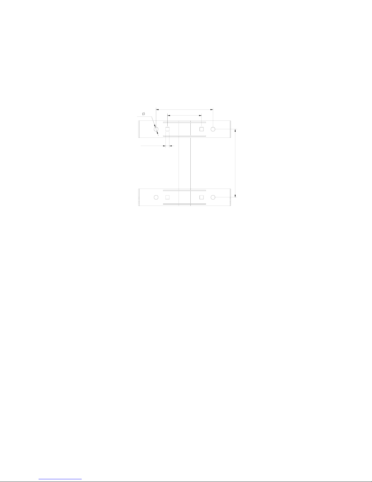
The mounting rack of RRU is for mounting the equipment to either a wall or on a pole. There are four
holes in total catering for the two mounting options:
• Wall mounting with the masonry bolts supplied, which make use of the round holes.
• Pole mounting with the clamp kit supplied, which make use of the square holes.
200
120
4-13*13
240
4- 15
Figure 10: RRU Mounting Rack Dimension
The mounting rack of RRU is pre-installed to the RRU enclosure prior to shipment. Before
commencing with wall or pole mounting, user needs to unscrew and remove each set of hex bolts
(M8x20) on the equipment with a ring spanner. The RRU mounting rack can then be separated from
the equipment in preparation for subsequent mounting tasks.
Page 23
INSTALLATION GUIDE FOR RA-8000
RA-8000 QI Copyright - refer to title page Page 23
ENU Status : 1-0-0
3.3.6 RRU LIFTING LUG
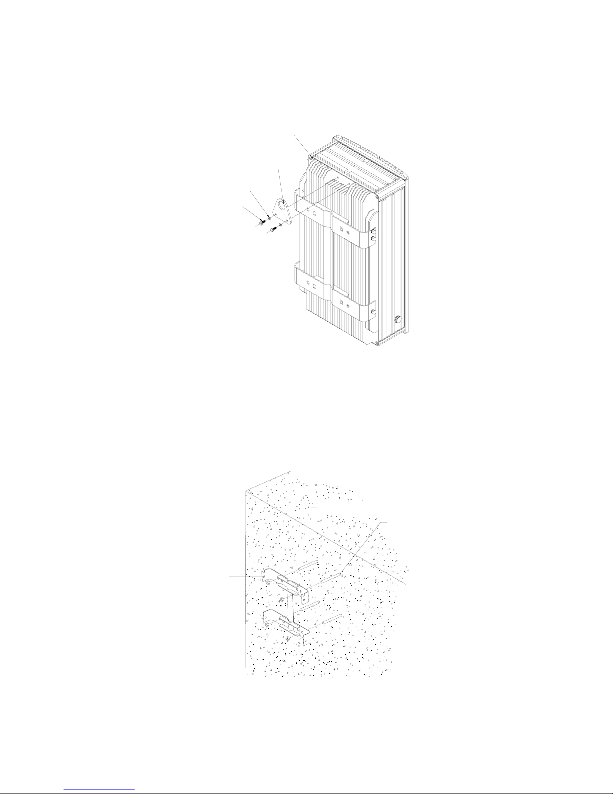
This is provided to facilitate lifting and positioning of the RRU equipment during installation. The lifting
lug is to be attached to the rear of the RRU enclosure as shown below.
Enclosure
Spring Washer M6
Lifting Lug
Hex Bolt M6x12
Figure 11: RRU Enclosure Lifting Lug Attachment Details
3.3.7 WALL MOUNTING OF RRU MOUNTING RACK
• Drill holes on the wall by using the position of the four round holes on the mounting rack as a
guide.
• Insert the masonry bolts M10 x 110 through the round holes and tighten them to take the weight
of the entire equipment.
Mounting Rack
Masonry Bolt
M10x110
Figure 12: RRU Mounting Rack Wall Mounting
Page 24
INSTALLATION GUIDE FOR RA-8000
RA-8000 QI Copyright - refer to title page Page 24
ENU Status : 1-0-0
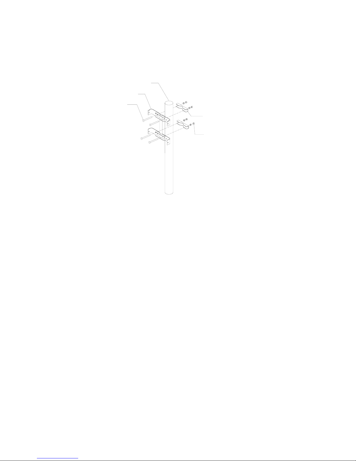
3.3.8 POLE MOUNTING OF RRU MOUNTING RACK
• The equipment can be mounted on customer-located poles of about 60~75mm in diameter.
• Secure the mounting rack onto the pole using M12X160 carriage bolts and clamps through the
square holes.
M12 x 160
carriage bolt
Mounting rack
Pole
M12 nut
Clamp
Figure 13: Pole Mounting of RRU Mounting Rack
Page 25
INSTALLATION GUIDE FOR RA-8000
RA-8000 QI Copyright - refer to title page Page 25
ENU Status : 1-0-0
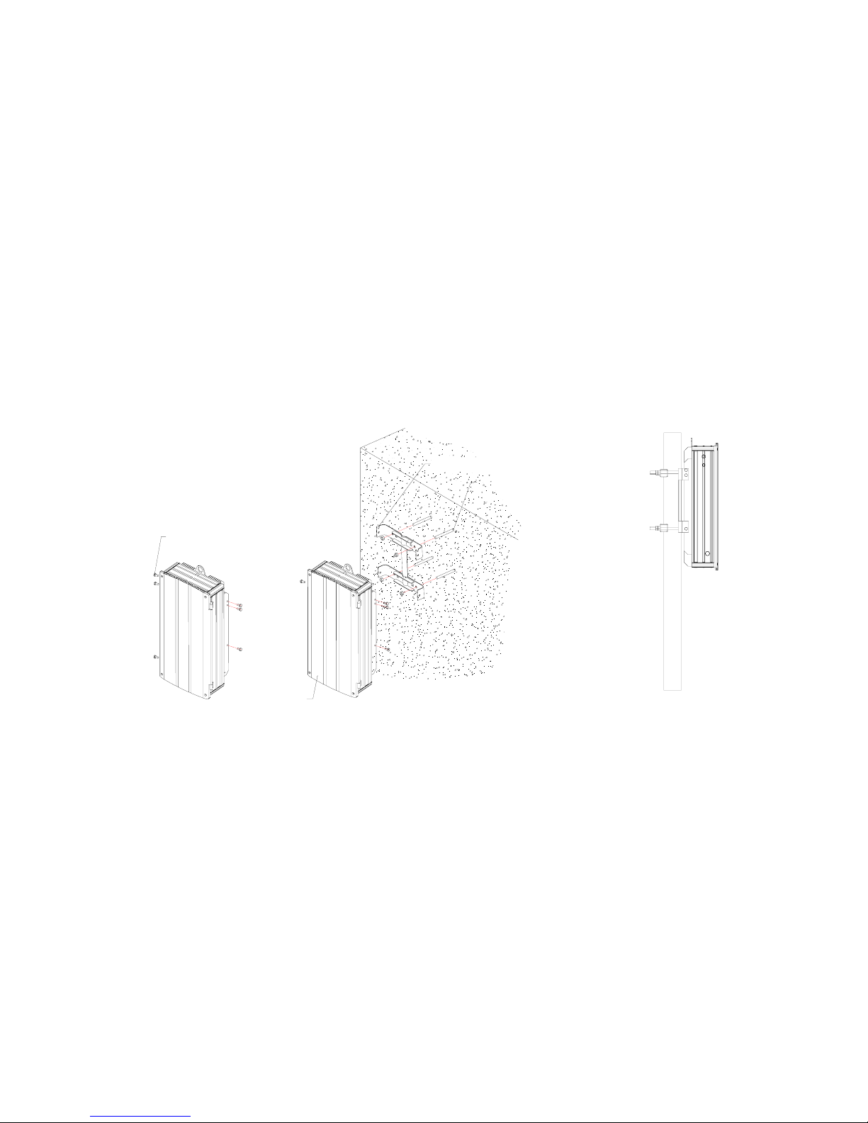
3.3.9 ATTACHING RRU ONTO MOUNTING RACK
y Located on the rear of the RRU enclosure is the array of protruding vertical cooling fins.
y The two outer fins are designed for attaching the enclosure to the mounting rack. Each of these
fins has two steel shims inserted – one towards the top and the other towards the lower end of
the each outer fin.
y Ensure each M8 bolts has a spring loaded washer and a flat washer.
y Partially thread the M8x20 hex bolts (1, 3, 4, and 6) onto each steel shim.
y Hang the equipment to the top of the mounting rack so that the top hex bolts (1 and 4) will take
the weight of the equipment.
y Push the lower end of the equipment to engage the two lower bolts (3 and 6) onto the mounting
rack.
y Tighten the four partially threaded hex bolts to secure the equipment onto the mounting rack.
y Insert two more hex bolts (2 and 5) through the mounting bracket and tighten them to the steel
shim.
y The above steps will mount the equipment firmly. Refer to the photograph in the “Mounting
Bracket” section to verify the correct arrangement of spring loaded and flat washers.
Enclosure
Masonry Bolt
M10
x110
Mounting Rack
Hex Bolt M8x20
3
2
1
5
4
6
Wall Mounting Pole Mounting
Figure 14: Attaching the RRU onto the Mounting Rack
3.3.10 DRIP-LOOP
Comba recommends that every horizontal cable entry to the equipment forms a 'U' before it’s entry to
the equipment. Any accumulated water on the cable will drip down at the bottom of the loop and will
not climb up to the equipment.
Page 26
INSTALLATION GUIDE FOR RA-8000
RA-8000 QI Copyright - refer to title page Page 26
ENU Status : 1-0-0
3.4 EQUIPMENT CONNECTORS
The MOU is connected via the connectors located on the front and back panel. The RRU is designed
for all cables entries from the bottom of the enclosure. The figures below present the connectors of
MOU and RRU.
3.4.1 MOU CONNECTORS
3.4.1.1 MOU Front Panel Connectors
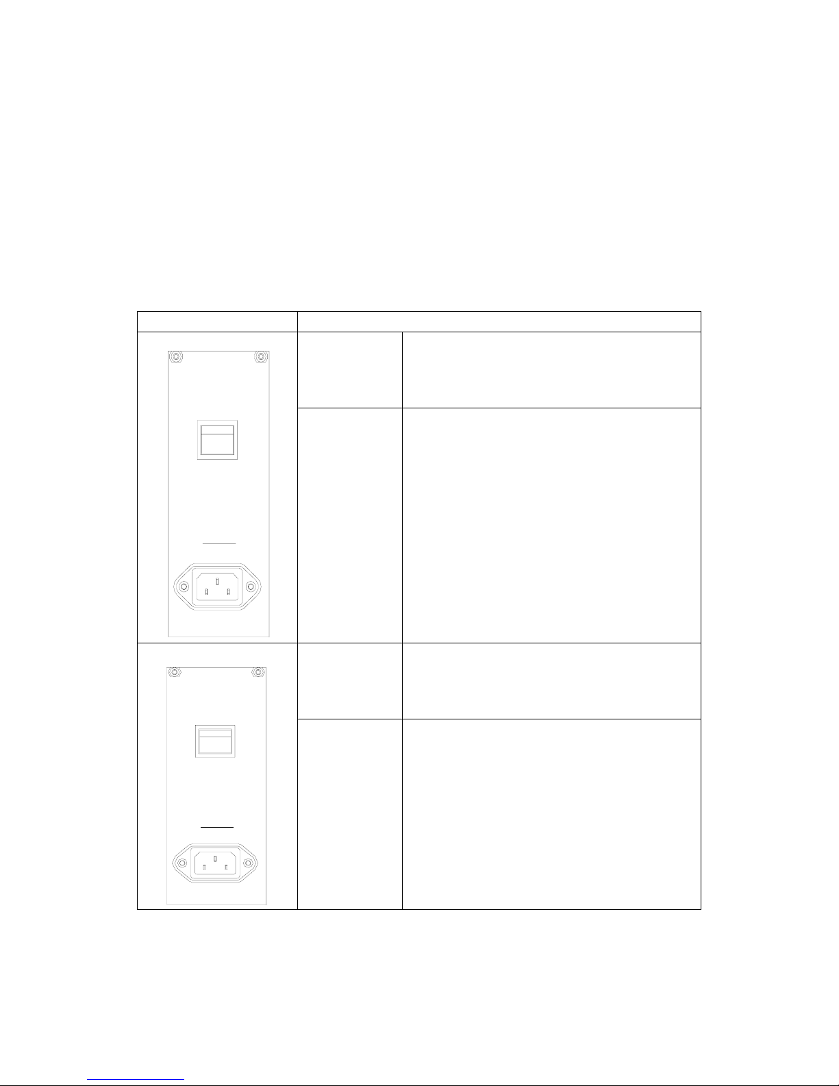
Depending on customer’s requirement on AC or DC power supply; there are three options for PSU
slide-in unit shown as below:
PSU unit
The front layout of the AC and DC PSU are shown.
POWER Power switch
AC110V PSU
50/60Hz
POWER
PSU
90~130V
90~130V
50/60Hz
IEC socket for standard power cord. 90~130V
50/60Hz indicates the input power is rated at
AC110V with the voltage range from 85V to
135V.
POWER Power switch
AC220V PSU
PSU
POWER
200~240V
50/60Hz
220~240V
50/60Hz
IEC socket for standard power cord. 220~240V
50/60Hz indicates the input power is rated at
AC220V with the voltage range from 176V to
264V
Page 27
INSTALLATION GUIDE FOR RA-8000
RA-8000 QI Copyright - refer to title page Page 27
ENU Status : 1-0-0
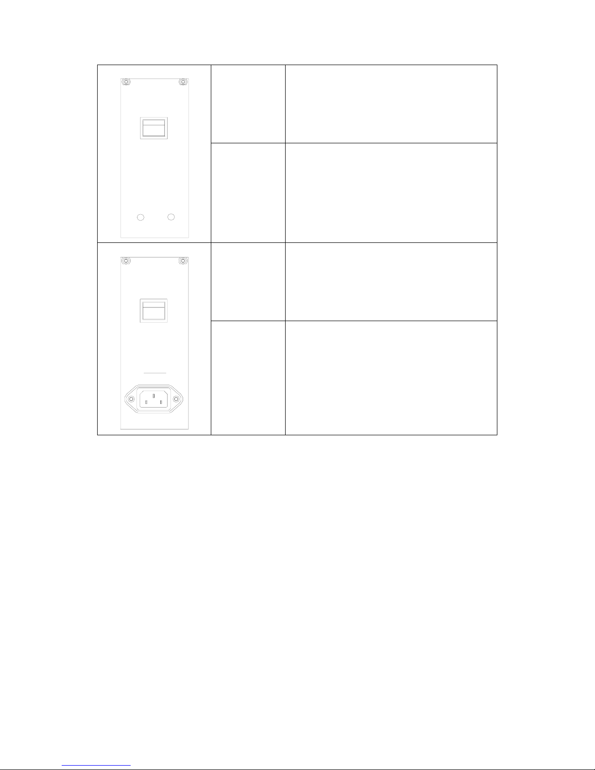
POWER Power switch
DC-48V PSU
POWER
PSU
-76~-38V
GND
-76~-38V
-76~-38V indicates the input power is rated at DC
with the voltage range from -76V to -38V.
Terminal posts on the front terminate the DC
power lead.
POWER Power switch
AC220/110V PSU
50/60Hz
100~240V
POWER
PSU
100~240V
IEC socket for standard power cord. 100~240V
50/60Hz indicates the input power is rated at
AC220V with the voltage range from 85V to
264V.
Table 6: PSU SIU Description
Page 28
INSTALLATION GUIDE FOR RA-8000
RA-8000 QI Copyright - refer to title page Page 28
ENU Status : 1-0-0
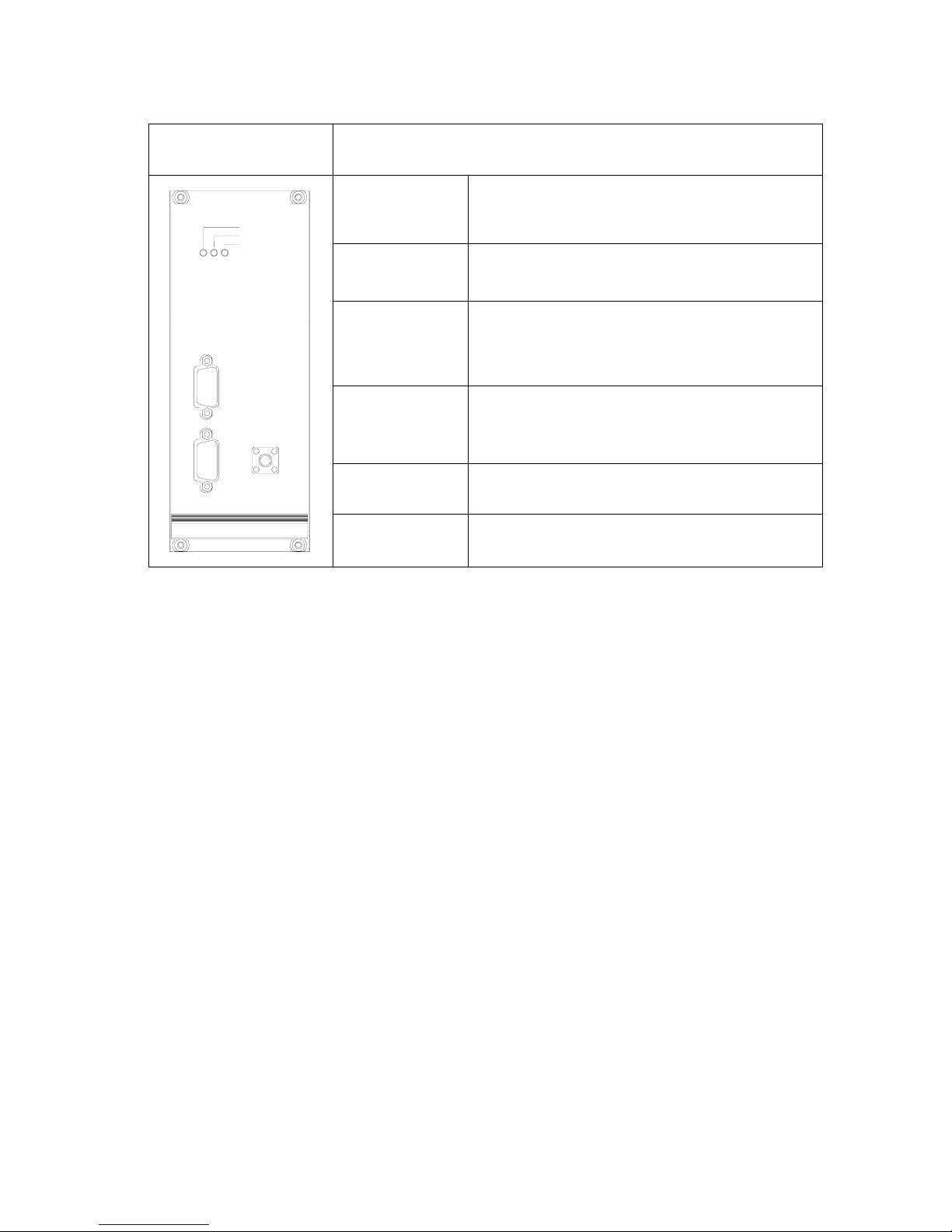
MCU unit
The MOU is controlled and monitored with this unit. The operation status
and local connection to PC is realized on this module. The
wireless/wireline modem is integrated within this unit.
RUN
Green LED to indicate system operation status. This
LED flashes every one second to indicate system
self-checking completes and system commissioning
can be started with.
ALM
RED LED to indicate the alarming condition of
MOU. ‘OFF’ for normal operation, and ‘ON’
indicates that an alarm is generated.
FSK
Green LED to indicate the communication status
(FSK Modem) between MOU and RRU. This LED
flashes every two seconds to indicate normal
communication status. “OFF” to indicate an alarm is
generated.
MODEM RF connector for antenna of MODEM
BTS-ALM
DB-9 connector for BTS alarm port to realize the
control & monitoring of RA-8000 at BTS. (option)
MCU
FSK
ALARM
RUN
RS-232
BTS-ALM
MODEM
RS-232
DB-9 connector for OMT PC connection to the MOU
by using the cable supplied.
Table 7: MCU SIU Description
Page 29
INSTALLATION GUIDE FOR RA-8000
RA-8000 QI Copyright - refer to title page Page 29
ENU Status : 1-0-0
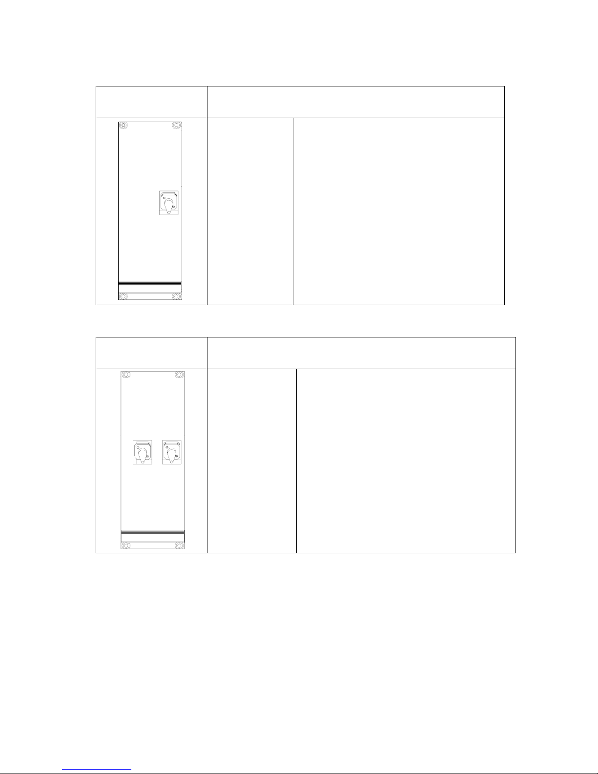
The following are the introduction on the connectors of the two types of FOU.
Single Channel FOU
It implements the connection between MOU and RRU through fiber.
Each Single Channel FOU can serve one RRU.
FOU
OP/DL_UL
OP/UL_DL
FC/PC connector for uplink/downlink optical
input/output port.
Table 8: Single Channel FOU SIU Description
Dual Channel FOU
It implements the connection between MOU and RRU through fiber.
Each Dual Channel FOU can serve two RRUs.
FOU
OP/DL_UL
OP/DL_UL
OP/UL_DL
FC/PC connector for uplink/downlink optical
input/output port.
Table 9: Dual Channel FOU SIU Description
Page 30
INSTALLATION GUIDE FOR RA-8000
RA-8000 QI Copyright - refer to title page Page 30
ENU Status : 1-0-0
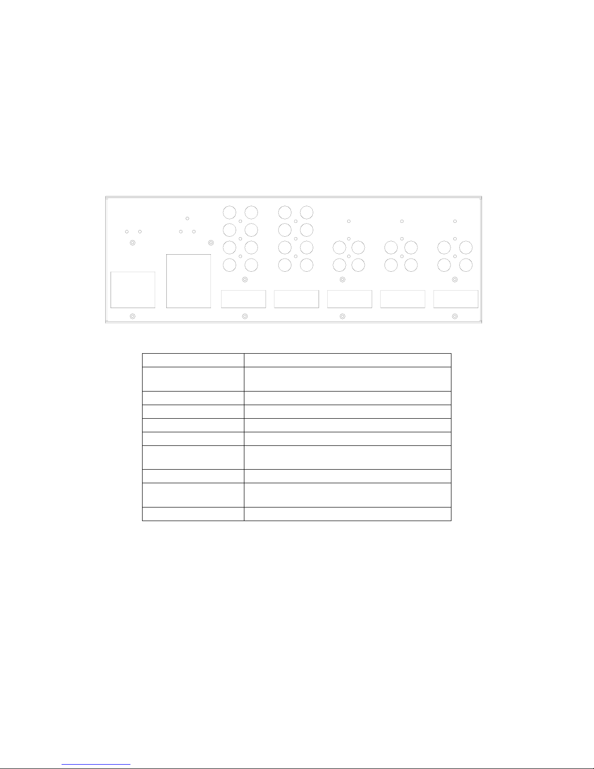
3.4.1.2 MOU Back Panel Connectors
Information in this section is provided for trained personnel, it is expected the MOU shelf is preconfigured and tested prior to shipment, and access to the rear of the MOU shelf is not normally
required.
The rear of the MOU shelf is protected by a screwed down back-cover, with the back-cover removed,
the backplane and RF connections are exposed. Operating the equipment without the MOU backcover fitted is not recommended.
E4
E3E1
E2D4
D3D1
D2
C4
C3C1
C2
B8
B7
B6
B5B1
B2
B3
B4A8
A7
A6
A5
A4
A3
A2
A1
Figure 15: MOU Back Panel View
Connector Description
A1~A4 RFU downlink output ports 1~4 ( A1 and A4 are
disable and reserved for extension units)
A5~A8 RFU uplink input ports 1~4
B1~B4 Reserved
B5~B8 Reserved
C1~C4 Reserved
D1~D2 FOU RF downlink input port 1
Port 2 (D2) reserved
D3~D4 FOU RF uplink output ports 3~4
E1~E2 FOU RF downlink input ports 1
Port 2 (E2) reserved
E3~E4 FOU RF uplink output ports 3~4
Table 10: MOU Back Panel Connectors
Page 31
INSTALLATION GUIDE FOR RA-8000
RA-8000 QI Copyright - refer to title page Page 31
ENU Status : 1-0-0
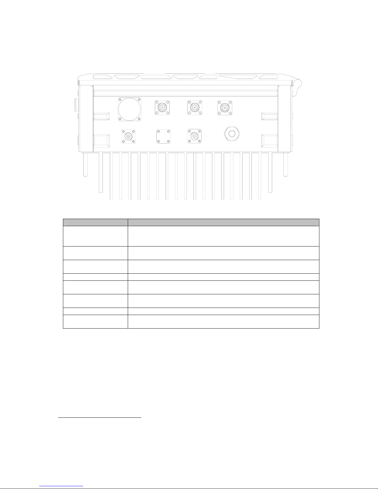
3.4.2 RRU CONNECTORS
Connectors on the RRU are identified below:
RS-485
TX_EXT
RS-232
100-240V~
50/60Hz
RX_EXT
EXT_ALM
MT
OP/UL_DL
Figure 16: RRU Connectors
Connector Description
OP/UL_DL Cable gland of FC/APC connector for UL and DL optical signal
connection. The “OP/UPLINK” and “OP/DOWNLINK” ports will be
identified when WDM unit is not configured into the system.
TX_EXT RF connector (reserved), for connection to the downlink input port of
extension unit (optionally supplied). A load will be applied when unused.
RX_EXT RF connector (reserved), for connection to the uplink output port of
extension unit (optionally supplied). A load will be applied when unused.
MT N-F connector for connection to service antenna.
RS-485 Reserved for connection to extension unit with the optionally supplied
communication cable.
RS-232 Communication port for local commissioning of the RRU with the
supplied commissioning cable.
EXT_ALM 7-Pin CPC connector for connection to external facilities.
100-240V~50/60Hz1 A pre-installed power cord provided for connection to AC supply (e.g.
110V, 220V, and 220/110V).
Table 11: RRU connectors
1
The voltage identification is a variant due to electricity system diversity of global regions. The power
cable gland might be identified for AC 220V, AC 110V, AC 220V/110V, DC -48V, or DC +24V
respectively. Please refer to specific product or contact local sales if any doubt.
Page 32

INSTALLATION GUIDE FOR RA-8000
RA-8000 QI Copyright - refer to title page Page 32
ENU Status : 1-0-0
3.5 EQUIPMENT CONNECTION
3.5.1 GROUNDING CONNECTION
Ground connection
To ensure safe operation of the product, a ground (earth) connection is required. For single phase AC
power source, the product must be grounded by connecting the “earth wire” of the power cord to the
ground terminal of the AC supply. For operating this product with DC power system (such as
rectifiers), the product should not be connected to power systems that switch open the return lead
because the return lead could function as the ground (earth) connection for the equipment.
Protective Ground Connection
The enclosure must be grounded securely by connecting a copper wire (CSA 16mm
2
) to the
grounding terminal on the equipment/rack, and the other end to a protective ground (i.e. building earth
point). An internationally acceptable colour code of the ground connection wire is green/yellow.
Such a ground connection implements the “Protective Ground Connection”, and must be connected
to the equipment at the designated ground point. In general, do not connect the supply before
establishing an adequate ground (earth) connection.
MOU Grounding Connection
Connect the grounding terminal located on the back panel of MOU to a protective ground (i.e. building
earth point).
RRU Grounding Connection
The equipment must be grounded securely. Connect a copper wire to the grounding terminal on the
mounting tab/rack, and connect the other end to a protective ground (i.e. building earth point). An
internationally acceptable coloring code of the ground connection wire is green/yellow.
3.5.2 SERVICE VOLTAGE CONNECTION
MOU Service Voltage Connection
MOU accepts AC or DC power depending on the type of PSU installed.
• For AC PSU (220V or 110V or 220/110V) – The power connector is on the front of the PSU
module. Connect the PSU to AC mains power outlet using a standard IEC power cord.
• For DC PSU – When the equipment is required to be DC power supply, the power connector
located on the front panel of PSU unit will be connected to the DC power source. The connectors
are colour coded for rectifying equipment in the BTS installation using power cable with CSA of
2mm
2
.
y Un-terminated colour coded wires are supplied, during installation, these are to be terminated
to the appropriate length, and crimp connectors applied before attaching securely onto the
appropriate connections of the PSU SIU.
y The DC power cable for -48V is colour coded, typically as BLUE for “-48V” or “Battery” and
BLACK for “0V” or “Return” connections.
y The DC power cable for +24V is colour coded, typically as RED for “+24V” or “Battery” and
BLUE for “0V” or “Return” connections.
Page 33

INSTALLATION GUIDE FOR RA-8000
RA-8000 QI Copyright - refer to title page Page 33
ENU Status : 1-0-0
RRU Service Voltage Connection
The RRU is connected to a 220/110VAC, 50Hz power supply. The recommended AC connection is
rated at AC220/110V, 10A and has three connections to include earth. This connection is labeled ‘AC
in’ adjacent to the power cord.
3.5.3 LI-ION BATTERY CONNECTION
Li-ion battery is provided with the MOU and RRU to ensure power is supplied to the system
monitoring unit and MCU and to ensure the alarm message could be sent to OMC effectively in case
of mains power failure.
Caution: Be careful of the risk of explosion if battery is replaced by an incorrect type. Do not handle
damaged or leaking lithium-ion batteries. Fire or chemical hazard if mistreated. Do not disassemble.
Dispose of properly consult your local regulations or waste disposal provider.
MOU Li-ion Battery Connection
The Li-ion battery is located within each PSU SIU and is disconnected prior to shipment. Before
equipment power up, user needs to withdraw the PSU SIU from the MOU shelf, locate and connect
the in-line connector of the battery pack and then reinsert the PSU SIU.
RRU Li-ion Battery Connection
The Li-ion battery pack exits inside the RRU. With the equipment lying flat, remove the bolts with an
Allen Key, unlock and open the enclosure door. Locate the battery pack, the in-line connector of the
battery pack is “disconnected” from the PSU during shipment. Connect the in-line connector, turn on
the battery switch located on the PSU, close the enclosure door, insert and tighten bolts to complete
this procedure.
3.5.4 RF CONNECTION
Connect MOU to BTS
Connect the “Uplink/Downlink” port located on RFU of MOU unit to the coupler (TX/RX) of BTS via
co-axial cable.
Connect RRU with Antenna
Connect the “MT” port of RRU with service antenna via coaxial cable.
Page 34
INSTALLATION GUIDE FOR RA-8000
RA-8000 QI Copyright - refer to title page Page 34
ENU Status : 1-0-0
3.5.5 OPTICAL CONNECTION
The MOU is connected to RRU via optical fiber (length < 20km). Connect the “OP/UL_DL” ports of
FOU1 to the “OP/UL_DL” port of RRU using separated TX/RX optical fibers.
On the RRU, the fiber entry is protected by a shroud; ensure this is attached after fibers are secured.
3.5.6 EXTERNAL ALARM CONNECTION
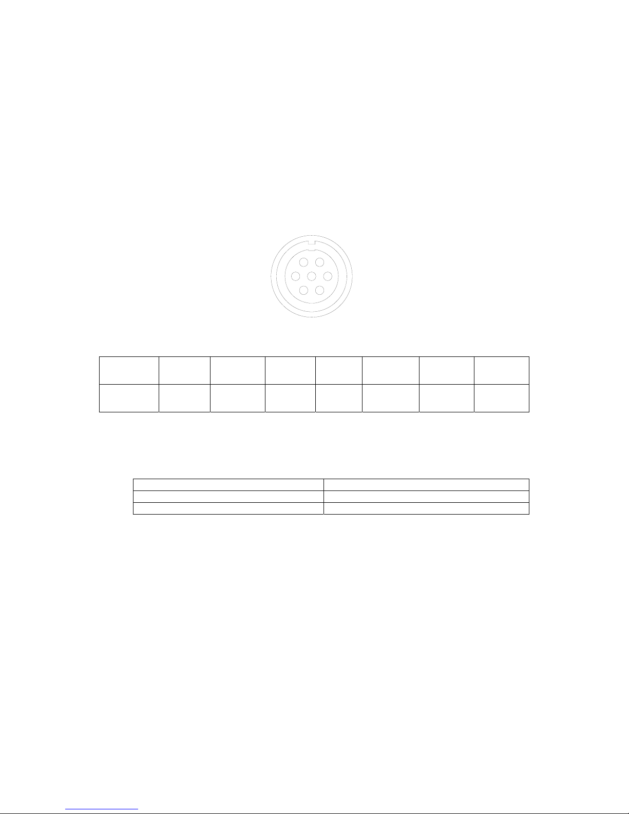
Four external alarms INPUT to RRU are realized on the “EXT_ALM” port, this is a 7-pin CPC
connector. The following figure and table shows the pin allocation and definition. Pin numbering are
shown looking-into the connector on the enclosure.
76
35
4
12
Figure 17: Pins Allocation for “EXT_ALM” Port
Pin
number
1 2 3 4 5 6 7
Alarm
definition
EXT.
Alarm 1
EXT.
Alarm 2
EXT.
Alarm 3
GND
EXT.
Alarm 4
Reserved Reserved
Table 12: Pin Definition of “EXT_ALM” Port
These signals are defined as “TTL/CMOS level”, for RRU, the following voltage are valid as
EXT_ALM signals:
Voltage as applied to EXT Alarm pin Alarm condition
0V to 1.5V Alarm recognized
3.5V to 5V No Alarm recognized
Table 13: Voltage Applied to EXT_ Alarm1~4
Page 35
INSTALLATION GUIDE FOR RA-8000
RA-8000 QI Copyright - refer to title page Page 35
ENU Status : 1-0-0
3.5.7 BTS ALARM CONNECTION
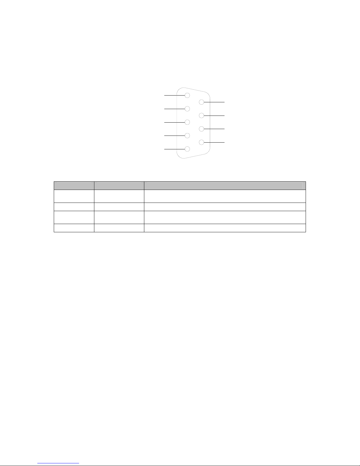
The equipment alarms can be signaled to the BTS via voltage-free relay contacts. The voltage-free
relay connections are connected to the DB-9 port “BTS_ALAM” located on the MCU of MOU. The
following figure and table shows the pin allocation and definition
1
2
4
3
5
6
7
9
8
BTS_OPEN
BTS_COM
BTS_ CLOSE
Figure 18: Pin Allocation for “BTS_ALM” Port
Pin Number Definition Description
1 BTS_OPEN
Connects to the normally open terminal of the voltage free
relay.
2
BTS_COM Connects to the common terminal of the voltage free relay.
3
BTS_CLOSE Connects to the normally close terminal of the voltage free
relay.
4 ~ 9 NC Reserved.
Table 14: Pin definition of the BTS_ALM port
Depending on OMT/OMC configuration, alarm to BTS can be signaled from RA-8000 by either: a)
pin1 and pin2 ‘open’ or b) pin2 and pin3 ‘close’.
Page 36
INSTALLATION GUIDE FOR RA-8000
RA-8000 QI Copyright - refer to title page Page 36
ENU Status : 1-0-0
3.5.8 MOU SHELF INTERNAL CONNECTION
Information in this section is provided for trained personnel, it is expected the MOU shelf is preconfigured and tested prior to shipment, and access to the rear of the MOU shelf is not normally
required.
The rear of the MOU shelf is protected by a screwed down back-cover, with the back-cover removed,
the backplane and RF connections are exposed. Operating the equipment without the MOU backcover fitted is not recommended.
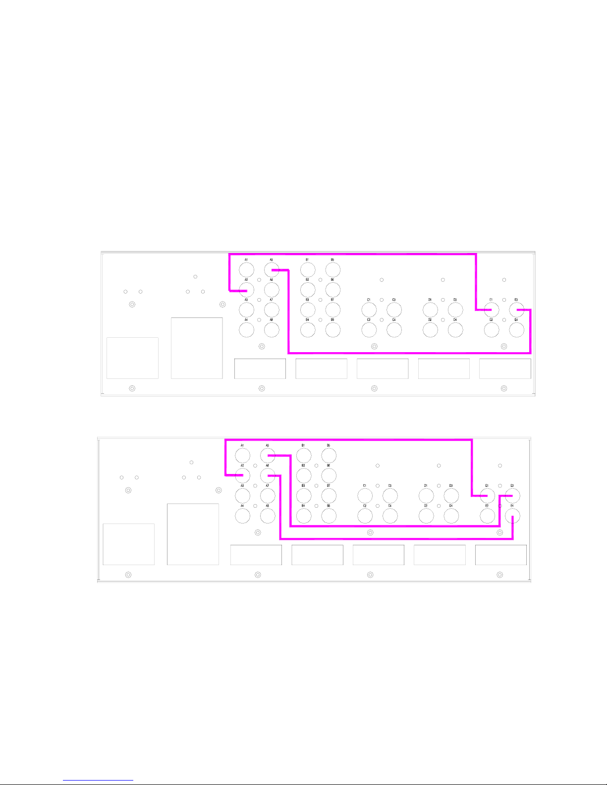
RF Connection between RFU and FOU Units
The figures below present how RFU is connected to FOU.
Figure 19: RF Connection between RFU and Single Output in FOU1
Figure 20: RF Connection between RFU and Two Outputs in FOU1
Page 37
INSTALLATION GUIDE FOR RA-8000
RA-8000 QI Copyright - refer to title page Page 37
ENU Status : 1-0-0
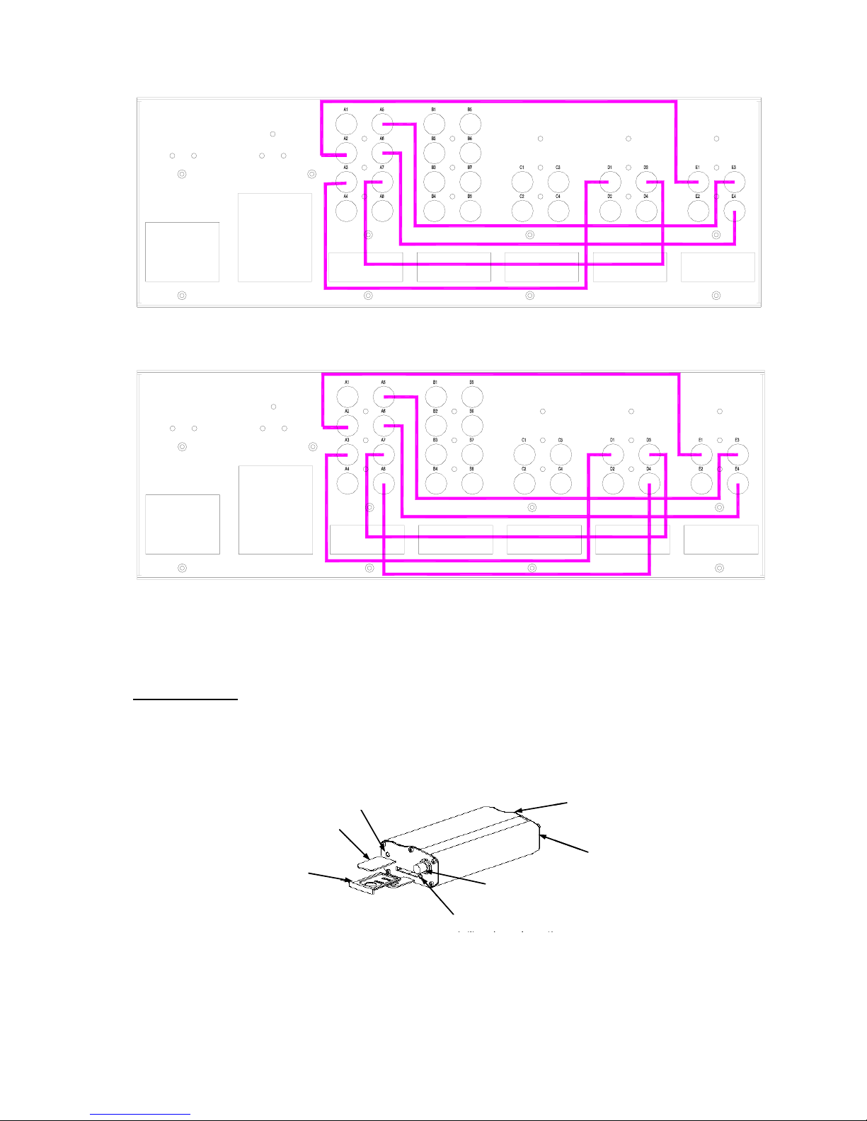
Figure 21: RF Connection between RFU and Two Outputs in FOU1, One Output in FOU2
Figure 22: RF Connection between RFU and Two Outputs in FOU1, Two Outputs in FOU2
3.5.9 INTEGRATED MODEM CONNECTON
Wireless Modem
There is wireless modem integrated in the MOU provides the option of remote connection of the
equipment by OMT/OMC. The wireless modem implements the link for data and SMS. The power
cable and data wire has already been connected to the wireless modem, customer only need to insert
the SIM card into the SIM card slot.
SIM card
SIM card carrier
Yellow button
Indicator LED
Modem RF output
(SMA connector)
RS232 port
Power port
SIM card
SIM card carrier
Yellow button
Indicator LED
Modem RF output
(SMA connector)
RS232 port
Power port
Figure 23: Wireless Modem
The LED indicator of the wireless modem displays the state of the modem:
Page 38
INSTALLATION GUIDE FOR RA-8000
RA-8000 QI Copyright - refer to title page Page 38
ENU Status : 1-0-0
z LED OFF: repeater power off
z LED ON: repeater power on, no SIM/UIM card or no connection to antenna
z LED flash slowly: repeater power on, in idle status
z LED flash quickly: repeater power on, in communication status
Note: For data link mode, it depends on whether service provider provides this function or not.
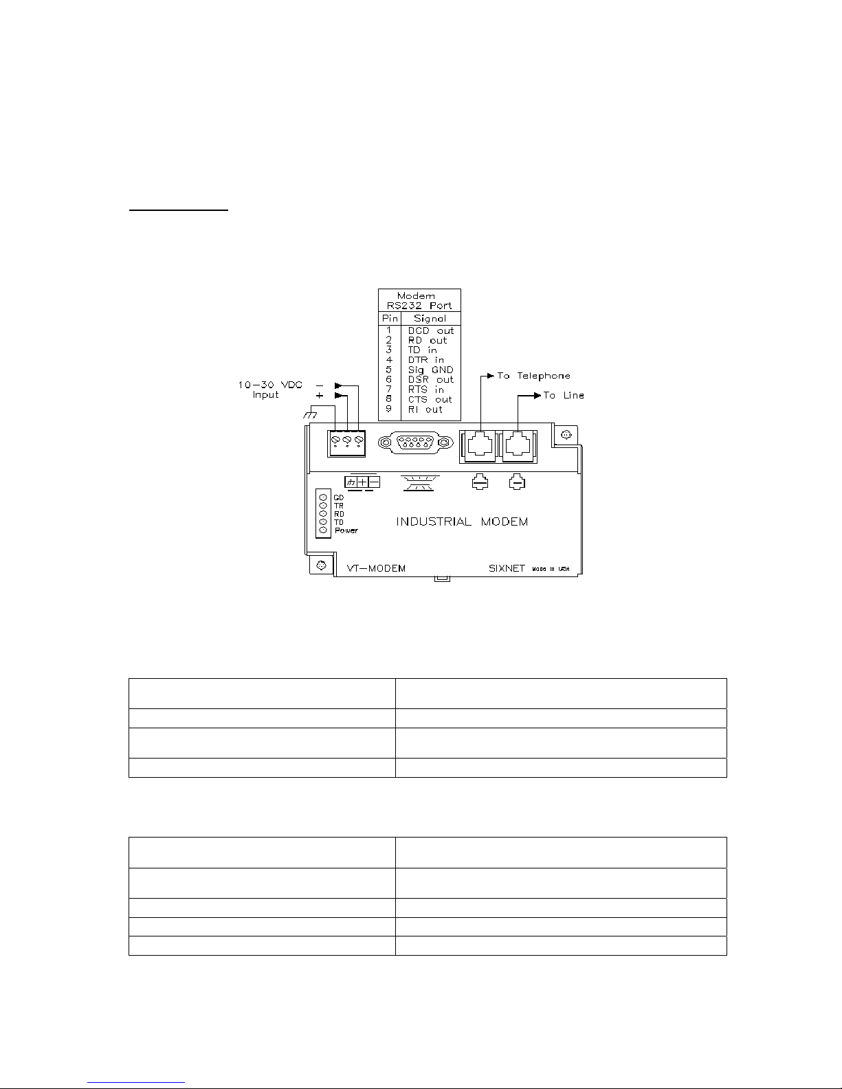
Wireline Modem
For the equipment variant equipped with the wireline modem, it is the wireline modem that
implements the link for data and alarm code. The following figure shows the diagram of the wireline
modem.
Figure 24: Diagram of wireline modem
RS232 and VDC Input ports are pre-wired to the equipment. The following table provides the
definitions of the main ports on the modem.
To Line
It connects the modem to the Public Switched
Telephone Network (PSTN).
To Telephone It connects to a telephone directly (optional).
RS232 Port
It is a ‘DB9’ port, connecting to the DB9 port on the
distribution board.
VDC Input Connects to 10 - 30 VDC.
On the modem, there are five status LEDs colored in red. Shown below are the definitions of these
LEDs.
CD (Carrier detect)
The modem has detected a carrier on the phone line (a
remote modem has been detected).
TR (Data Terminal Ready)
The PC (or SIXNET Station) has established a
connection to the modem and is ready.
RD (Receive Data) Flashes as data is received from the phone line.
TD (Transmit Data) Flashes as data is sent out the phone line.
Power ON when power is present.
Page 39

INSTALLATION GUIDE FOR RA-8000
RA-8000 QI Copyright - refer to title page Page 39
ENU Status : 1-0-0
3.5.10 CONNECT TO PC
The local commissioning and management for MOU and RRU is achieved through connecting to the
OMT PC locally.
Connect MOU to PC
Connect the RS-232 port located on the MCU of MOU to the serial port of PC with the RS-232 cable
supplied to achieve local monitoring and management.
Connect RRU to PC
Local commissioning and management of RRU is through the two methods stated below:
• With the equipment enclosure opened, the OMT PC can be connected internally. (Via X29 on the
distribution board) with a nine-PIN commissioning cable (R-9122C/R9122AC).
• The “RS-232” port located on the bottom of the enclosure is designed as a round connector for
local commissioning. An equipped conversion cable labeled “00-3GMC5J-3001” needs to be
used to interface the connection between the equipment enclosure and the commissioning cable.
End of Section
Page 40

INSTALLATION GUIDE FOR RA-8000
RA-8000 QI Copyright - refer to title page Page 40
ENU Status : 1-0-0
4 COMMISSIONING
4.1 PRE-COMMISSIONING TASKS
After equipment installation, perform the following steps before equipment powering and
commissioning, check that the expected voltage, current, and power levels do not violate any ratings.
Double check all connections including ground before applying power. Do not manipulate circuits or
make changes when power is applied:
• Visually inspect the power connection within the equipment. Ensure that the power cable is
correctly and securely connected, including grounding wire, RF cable and optical cable.
• Check grounding connection and verify that the ground resistance is less than 5Ω.
• Connect the equipment to the PC installed with OMT software.
• With the MOU installed, all SIU in place and cablings connected, apply power to the MOU by
switching on the PSU switch on the PSU SIU.
• With the MOU switched on, RRU installed and all cablings connected, apply power to the RRU by
switching on the PSU switch on the integrated PSU.
• Monitor the initialization of MOU and RRU wait until equipment initialization has completed.
• The online commissioning can be commenced with following the commissioning steps.
4.2 LED INDICATORS
4.2.1 MCU LED INDICATORS
Diagnostic LEDs are located on the MCU SIU, with each indicating the status of a particular function:
Identifier Colour Indication
RUN Green
Operation indicator – power is supplied to the MOU. Flashes once every
second to indicate normal system operation.
ALARM Red Alarm indicator. ON = alarm; OFF = no alarm
FSK Green
Diagnostic LED for FSK communication and MODEN operation, Flashes
once every two seconds to indication normal communication between MOU
and RRU.
Table 15: MCU LED Indicators
The LEDs RUN, ALARM, FSK will flash simultaneously three times during system self-checking after
equipment power-up. Then, RUN flashes every second to indicate system commissioning can
proceed.
4.2.2 RRU LED INDICATORS
Three diagnostic indicators are located on the MCU within the RRU, with each indicating the status of
a particular function.
Identifier Colour Indication
H1 Green Operation indicator – Power is supplied to the RRU. Flashes once every
second to indicate normal system operation.
H2 Red Alarm indicator. ON = alarm; OFF = no alarm
H3 Red Designed for integrated wireless modem status indicator. It is not
applicable for the RRU since it has no modem installed internally.
It keeps “ON” during equipment operation.
Table 16: RRU LED Indicators
Page 41

INSTALLATION GUIDE FOR RA-8000
RA-8000 QI Copyright - refer to title page Page 41
ENU Status : 1-0-0
MCU Initialization
All three diagnostic LEDs will flash simultaneously for three times when power is supplied to the
equipment. Then H1 will keep flashing at the rate of 1 flash/second. H2 will be ON when any alarm
occurs.
H3H2H1
Connect to Distribution Board
Push-button
switch
Figure 25: Location of RRU LED Indicators
On the MCU, there is a push-button switch (usually yellow) used to reset the equipment manually
when equipment initialization fails, or abnormal operation occurs, or when the equipment is reconnected to the OMT after powered off due to some reason.
4.3 OMT
The equipment can be monitored and controlled by OMT software running on a local PC with local
commissioning cable, remote connection to the equipment.
z OMT software running on a local PC with serial connection to the equipment.
z OMC (optional) software with remote connection to the equipment.
This chapter is to introduce how to apply local and remote connection to OMT for the first installation,
for the detailed OMT information, please refer to OMT user manual and other references.
Notice: The OMC software with remote connection to the equipment is optional for customers.
4.3.1 LOCAL AND REMOTE CONNECTIONS TO OMT
After installing OMT software on the PC, connection to the equipment can be done locally or remotely.
Double click the OMT explorer icon, the OMT Explorer main screen window will appear.
4.3.2 LOCAL CONNECTION TO OMT
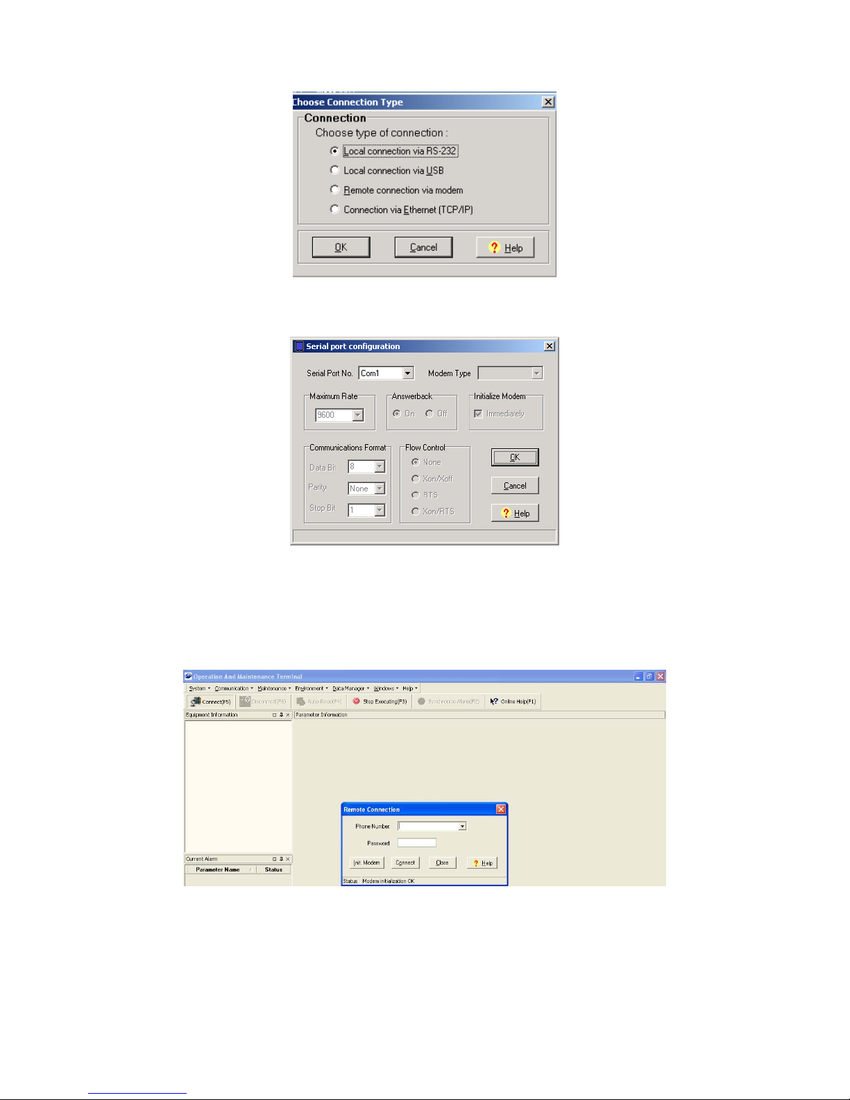
After database configuration is done successfully, the following window will pop up and select [Local
connection via RS-232] for local connection.
Page 42
INSTALLATION GUIDE FOR RA-8000
RA-8000 QI Copyright - refer to title page Page 42
ENU Status : 1-0-0
Figure 26: Connection Type
Select the desired communication port and click “OK”, it will enter into the main window of OMT.
Figure 27: Serial Port Configuration
4.3.3 REMOTE CONNECTION TO OMT
If remote connection is needed, users can select [Remote connection via modem] in connection type
window. Select desired serial port and click “OK” in [Serial Port Configuration] window to go to OMT
main window. Click “connect” and the [Remote Connection] window will show up.
Figure 28: Remote Connection
Config: Enter the correct phone number (Users don't have to enter the password) and click “connect”.
After the modem is initialized, it will be connected remotely.
Page 43
INSTALLATION GUIDE FOR RA-8000
RA-8000 QI Copyright - refer to title page Page 43
ENU Status : 1-0-0
4.3.4 OMT CONFIGURATION
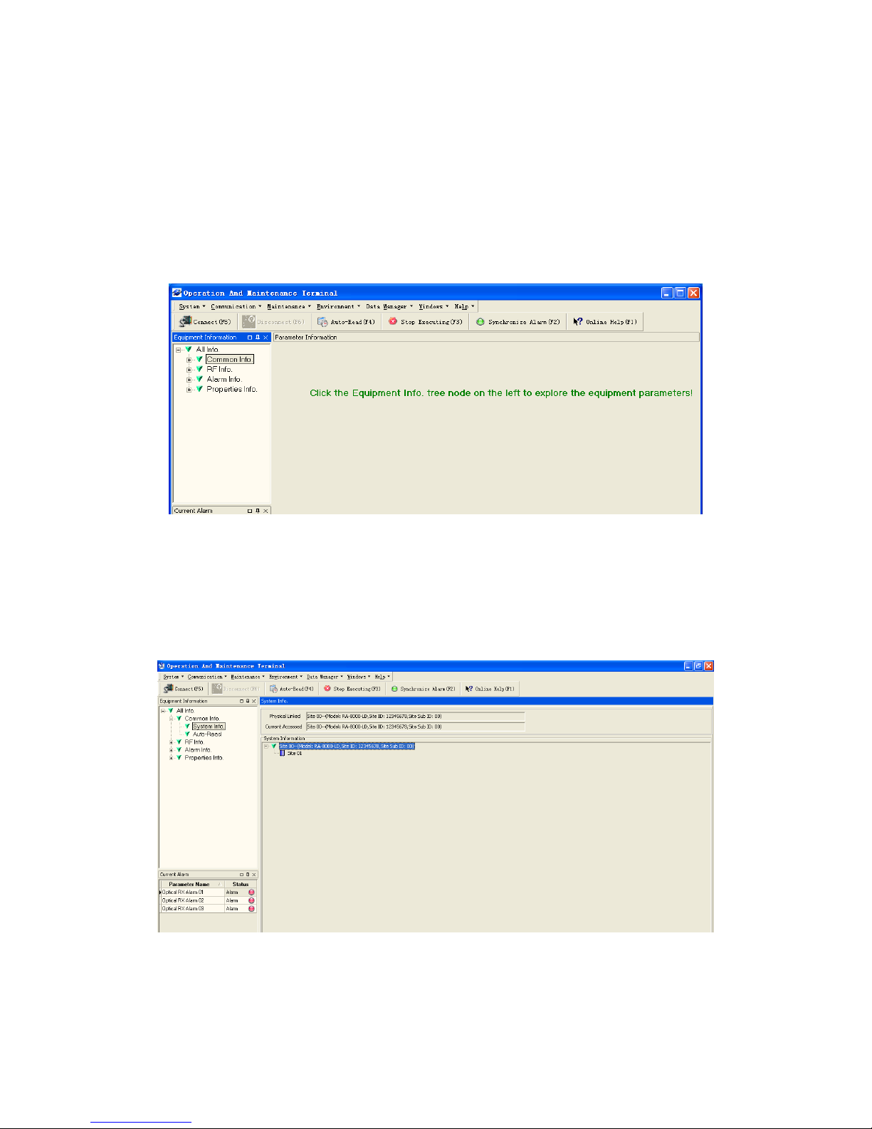
After entering the OMT main screen, click the”Connect” button on the toolbar, to connect the
equipment to the OMT. Successful connection will be indicated by a message “Online OK” and
equipment parameters can be read and/or set.
Users can configure the parameters, and then set the parameters according to desired coverage
level and interference to other BTS signals.
OMT parameters include: Common Information, RF Information, Alarm Information, and Properties
Information.
Figure 29: OMT Main Window
4.3.5 SYSTEM INFO
Click on [System Info.] within Equipment Information, system information will be displayed in the right
interface of the OMT screen. In the interface the site ID of MU is described and the currently
accessed unit is indicated.
Figure 30: System Information
There are two methods to switch from different sites.
z To switch to the MOU or other sites, customer can right click on the message indicating the not
accessed unit. Select [Switch] in the pop-up menu, RRU can be successfully switched to MOU or
other sites.
Page 44
INSTALLATION GUIDE FOR RA-8000
RA-8000 QI Copyright - refer to title page Page 44
ENU Status : 1-0-0
z To switch to the MOU or other sites, customer can choose MOU or other site which is under
monitoring, then click [Switch] on the bottom to switch to MOU or other sites.
4.3.6 RF PARAMETER
It is recommended to configure the following RF parameters for the first installation.
4.3.7 SWITCH
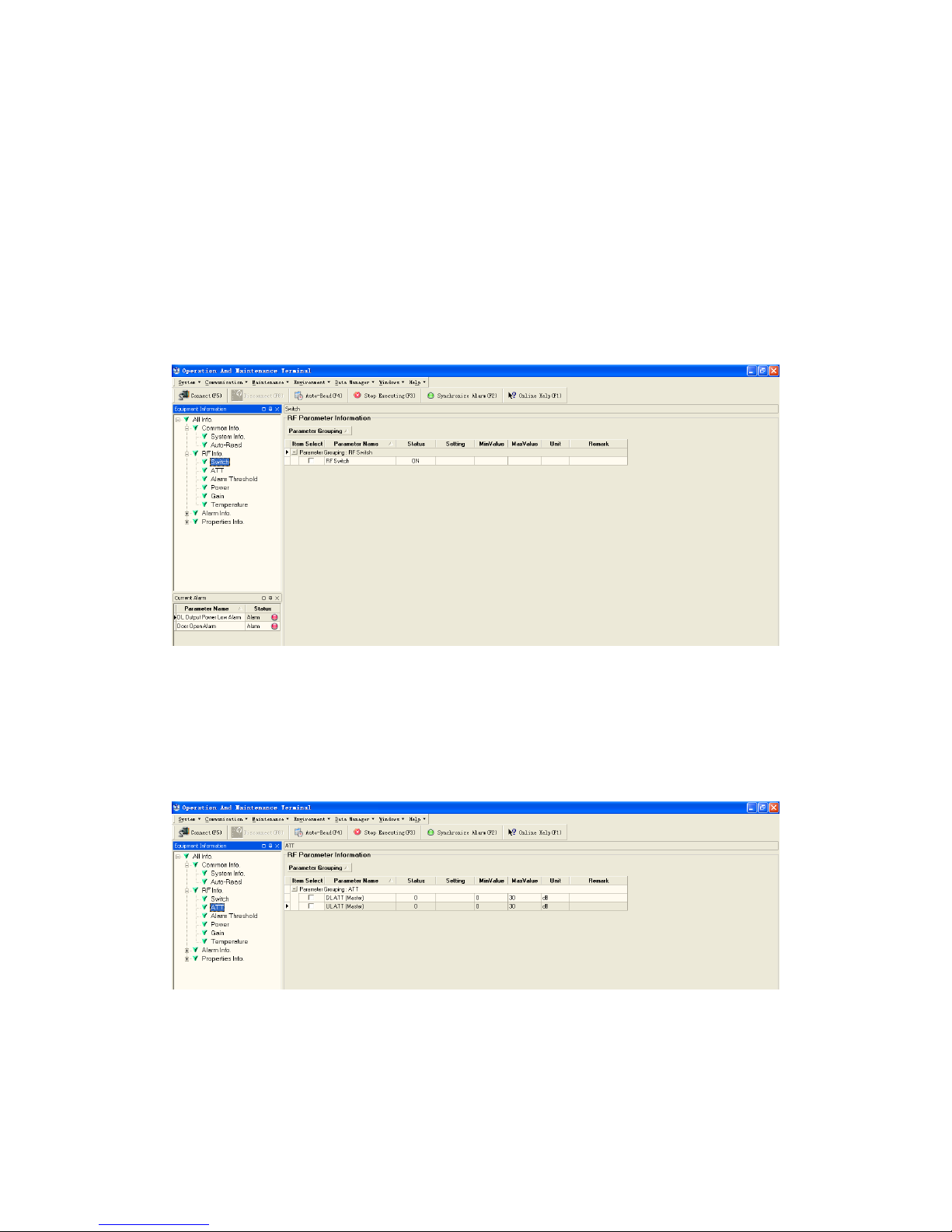
Switch is to enable/disable power for internal modules. When user checks and sets non-RF
parameters, such as checking physical antenna connection, switching off will disable equipment
power temporarily to protect PA in operation.
Figure 31: RRU Switch
Config:
Select the required state in setting columns of RF information window for RF switch, then press
[Enter] or [Config] button to finish the configuration operation.
4.3.8 ATT
Figure 32: MOU ATT
Config:
Select the required value in setting columns of RF information window for ATT, and press [Enter] or
[Config] button to finish the configuration operation.
Page 45
INSTALLATION GUIDE FOR RA-8000
RA-8000 QI Copyright - refer to title page Page 45
ENU Status : 1-0-0
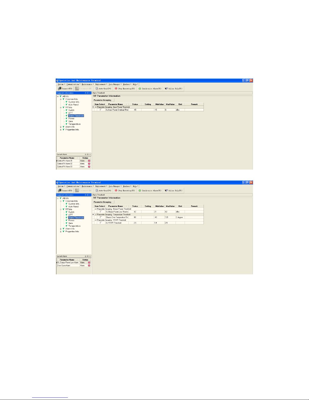
4.3.9 ALARM THRESHOLD
Alarm Threshold includes Power threshold and Temperature threshold.
Users can set alarm threshold according to the specific situation. If the measured value is lower than
the threshold lower limit or more than the threshold upper limit, the appropriate alarm will be
generated.
Figure 33: MOU Alarm Threshold
Figure 34: RRU Alarm Threshold
Config:
Enter the required value in setting columns of RF information window for Alarm threshold, and press
[Enter] or [Config] button to finish the configuration operation.
Notice: The input value must be in the range of power threshold.
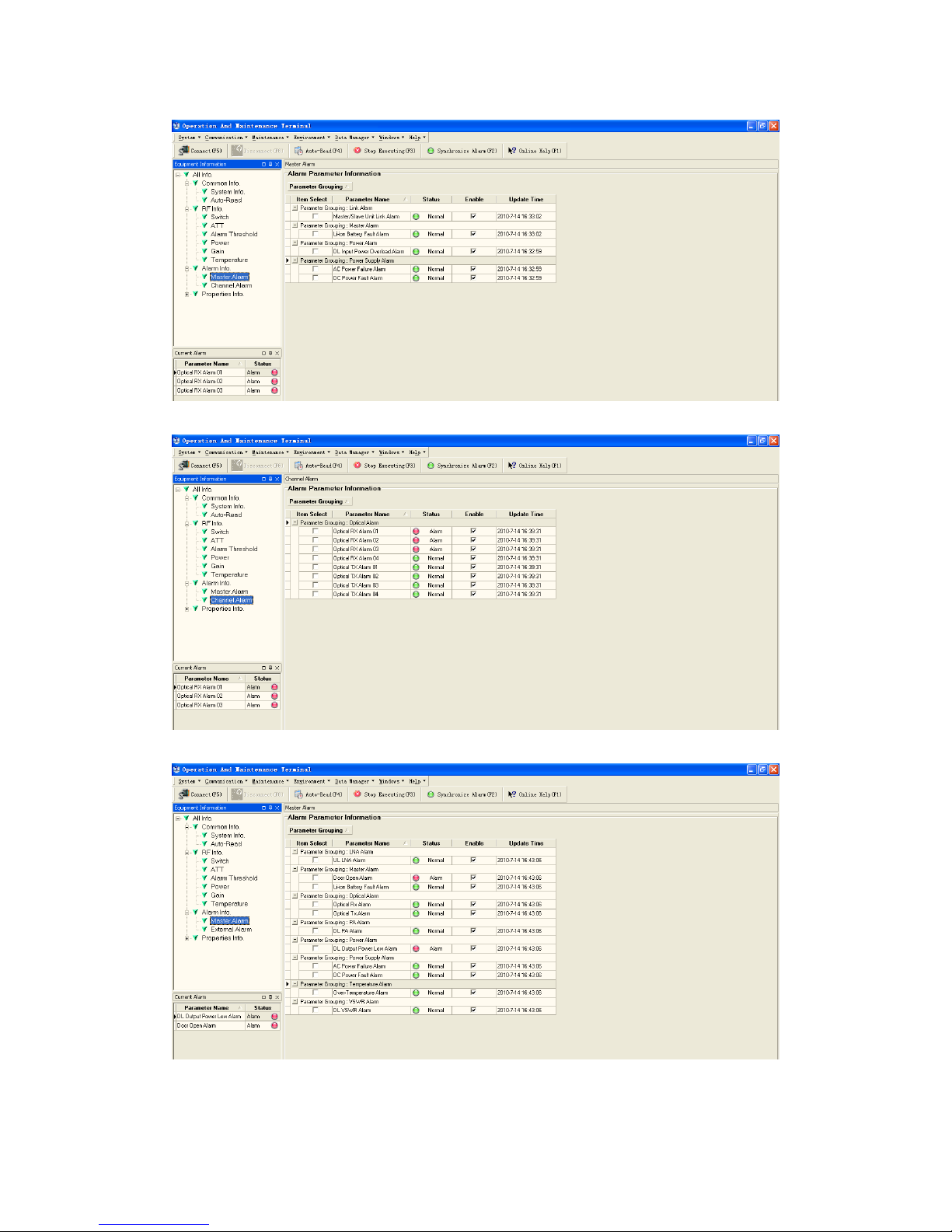
4.3.10 ALARM INFORMATION
Alarm information operation is to select alarm parameters for monitoring. MU alarm parameters
include Master Alarm, Channel Alarm; RU alarm parameters include Master Alarm and External
Alarm.
Click any tree node in [Alarm Info] group, [Alarm Parameter Information] window will appear in the
right side. The figures below show the alarm information.
Page 46
INSTALLATION GUIDE FOR RA-8000
RA-8000 QI Copyright - refer to title page Page 46
ENU Status : 1-0-0
Figure 35: MOU Master Alarm
Figure 36: MOU Channel Alarm
Figure 37: RRU Master Alarm
Page 47
INSTALLATION GUIDE FOR RA-8000
RA-8000 QI Copyright - refer to title page Page 47
ENU Status : 1-0-0
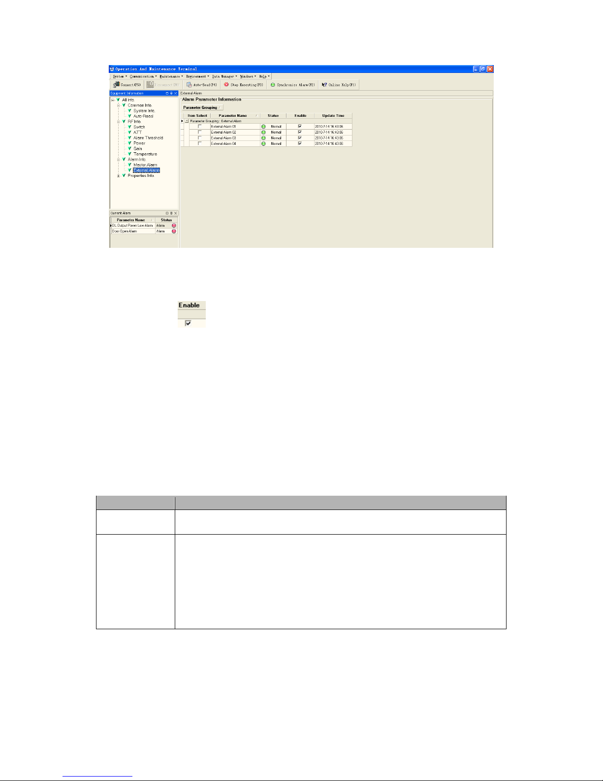
Figure 38: RRU External Alarm
Config:
Tick the check box of [Item select] and [Enable] of the desired parameters and click [config] button to
finish configuration operation.
Notice: [Enable] box
is to enable the alarm monitoring for system. Only if users enable the
alarm by ticking the [Enable] box, the alarms can be monitored by the OMT/OMC.
4.3.11 PROPERTIES INFORMATION
The property parameters include Equipment ID, Chip Info., Equipment Info., Site Location, Trigger
Report that are equipment specified. All properties information, in general, will be displayed in the
right part of the main screen when clicking on each node of the [Properties Info.].
4.3.12 EQUIPMENT ID
Equipment ID is to be configured after local commission has been completed, which includes Site ID
and Site Sub ID.
Item Description
Site ID Site ID is the unique equipment identification. It is a hexadecimal string of
eight characters in the range of [0x00000000-0xFFFFFFFF]. e.g. 12345678
Site Sub ID Site Sub ID is used for Master-Slave System. It is the unique identification of
each Master/ Slave Unit and is a hexadecimal string of two characters in the
range of [0x00-0xFF]
For the system located with single equipment, the Site Sub ID should be 0xFF.
e.g. 00
For Master-Slave system, the Site Sub ID for Master Unit is 0x00, and the Site
Sub ID for each Slave Unit is represented in the range of [0x00-0xFE] in
ascending order. e.g. Master Site ID: 00 Slave Site ID: 01
Table 17: Equipment ID
NOTE: User can setup the config in RU/MU via same RS232 connector. In order to establish a virtual
link between RRU and MOU, the RRU site sub ID should keep consistency with MOU site sub ID.
For example, the site sub IDs have been set as 01 in both RRU and MOU, double click on the RRU
sub ID to access RRU from MOU. For detail operation, please refer to [System Info.].
Page 48
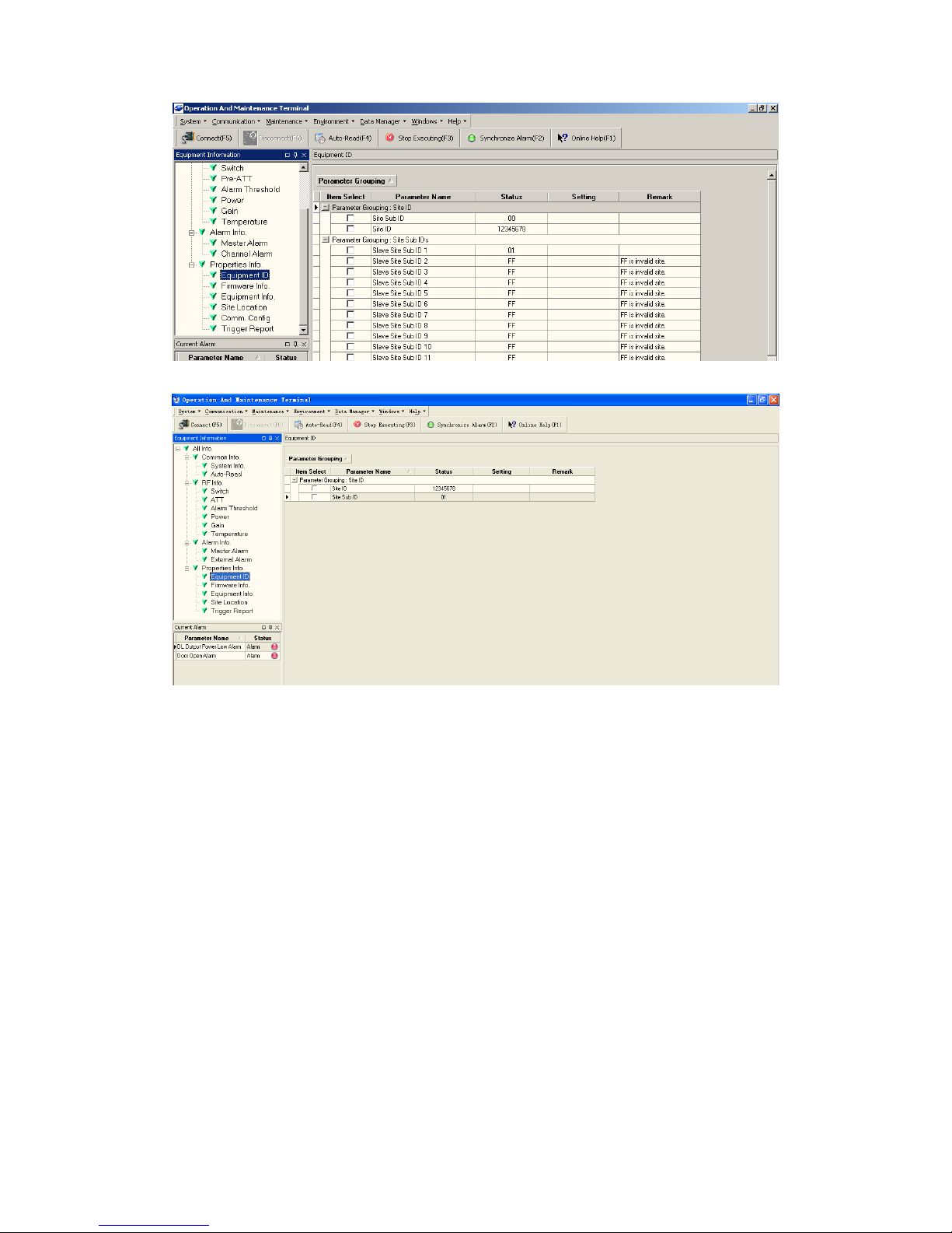
INSTALLATION GUIDE FOR RA-8000
RA-8000 QI Copyright - refer to title page Page 48
ENU Status : 1-0-0
Figure 39: MOU Equipment ID
Figure 40: ROU Equipment ID
4.3.13 COMM. CONFIG
If the equipment is to be monitored by OMC software, users must finish the MU [Comm. Config.] in
the next step.
The Comm. Config information requires to be manually entered by users after successful connection
to the equipment.
Page 49
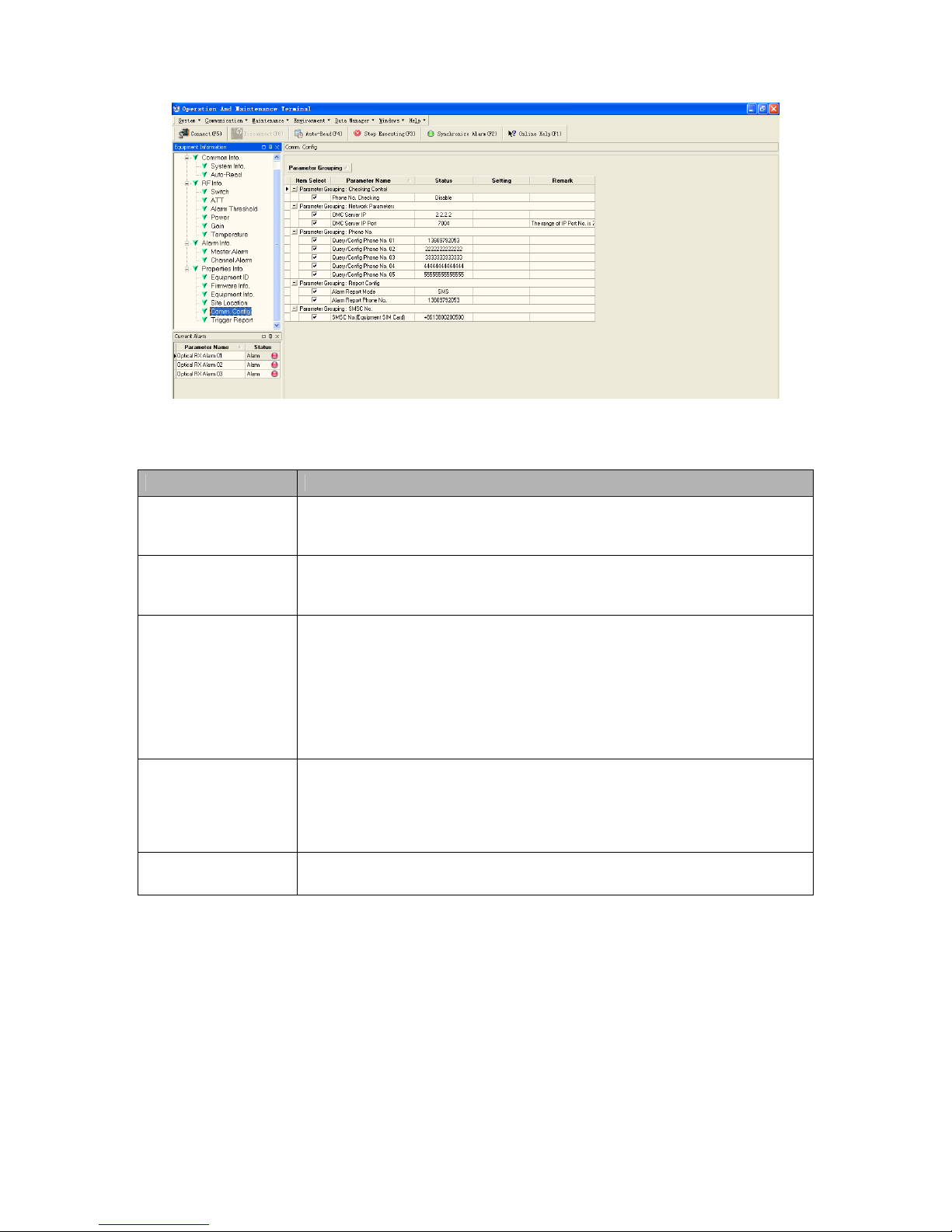
INSTALLATION GUIDE FOR RA-8000
RA-8000 QI Copyright - refer to title page Page 49
ENU Status : 1-0-0
Figure 41: MOU Comm.Config
See the table below for configuration details of each parameter.
Item Description
Checking Control Select “Enable” or “Disable” from the drop down menu as shown to enable or
disable the Phone Number Authentication feature. Refer to [Phone No.] in
details.
OMC Server IP Based on the current network conditions, users can enter the IP address
information of the equipment, which is connected to the OMT/OMC via
Ethernet. This connection via Ethernet is not available at this stage.
Phone No. This is designed for authentication purpose when remote connection via
modem is required. It is the phone number to dial the equipment. Only the
phone number pre-defined in this field, will it be allowed to dial the
equipment. It is required to manually enter the phone number. Up to 5 phone
numbers are allowed. The use of phone number authentication can avoid
unauthorized use of the OMT. In addition, it can prevent the equipment
receiving piles of spam short messages, thus help the operator greatly
reduce the cost.
Report Config The Report No. is the SIM card number of the modem built into the OMC
Server computer. The equipment will send alarm SMS to this number.
If remote communication is needed via modem, users have to enable SMS
mode and set the report phone No. by entering the SIM card number of the
equipment built-in modem.
SMSC No. It specifies the SMS center. Users have to set the service No. of SMSC for
the first installation, so that the alarms can be sent to OMC.
Table 18: Comm.Config.
Page 50

INSTALLATION GUIDE FOR RA-8000
RA-8000 QI Copyright - refer to title page Page 50
ENU Status : 1-0-0
4.3.14 DATA MAINTENANCE
Refer to OMT V4.0 Software Product Manual.
4.4 NON-VOLATILE MEMORY
A non-volatile storage device on the MCU holds the configuration of the equipment. The following
information is preserved in the event of power-loss:
Network Configuration
Device ID
SMS report mode including SMS center number and OMC report number setting
Operating Parameters
ATT
Switch
Output Power
Gain
Downlink Input Power
Alarm thresholds
Page 51

INSTALLATION GUIDE FOR RA-8000
RA-8000 QI Copyright - refer to title page Page 51
ENU Status : 1-0-0
4.5 COMMISSIONING PROCEDURES
Since end-to-end connection is available for the repeater’s OMT software, users can configure the
parameters at MOU, and then offset the parameters of MOU at RRU according to desired coverage
level and interference to other BTS signals. Perform the following procedures for system
commissioning.
• Locally connect to RRU(s) and set its site ID.
• Locally connect to MOU and set its site ID and network parameters. Then register the site ID of
RRU at MOU.
• Check the working status of MOU and RRU. If damage occurs, proceed with RMA process.
• At RRU, adjust downlink gain so that the output power can achieve the design requirement.
• At MOU, configure the uplink gain of MOU to make the UL output noise level to be lower than the
BTS noise threshold. Refer to the table below for the comparison between UL gain and UL output
noise level of MOU.
• Configure the UL gain of both MOU and RRU to ensure high quality communication link within the
desired area.
• Confirm no interference to BTS to complete commissioning.
End of section
Page 52
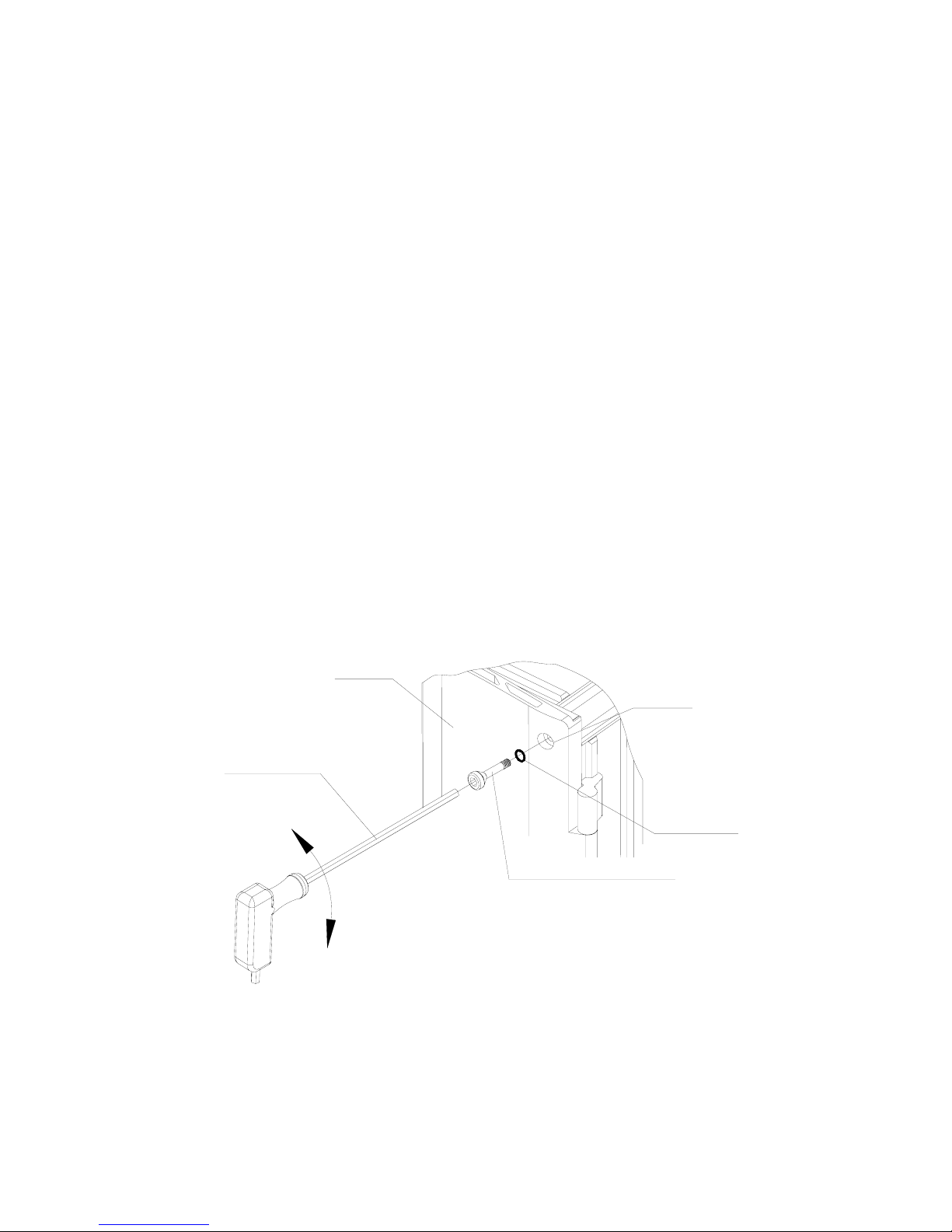
INSTALLATION GUIDE FOR RA-8000
RA-8000 QI Copyright - refer to title page Page 52
ENU Status : 1-0-0
5 MAINTENANCE
The equipment operation status can be observed remotely through OMT/OMC.
Periodic inspection of the repeater equipment(s) is recommended. The recommended tasks include:
• Measurement of the return loss of the feeder system.
• Ensure the stable connection of cables, power cords and facilities located indoor.
• Inspect and record operation status and parameters, such as receive signal level, output noise
level, DL output power of the repeater, from OMC or OMT.
• Check the PSU voltage of MOU.
• Verify that the actual coverage effects have not degraded.
• Check the working status of optical TX/RX power.
• Check the controlling and monitoring function.
• Verify lightning and grounding protection is in good condition.
• Ensure the labels are clear and legible.
• For Li-ion battery, verify their state. Deeply discharged battery should be return to Comba for
replacement. If the battery voltage drops under 16V within one hour, replacement of Li-ion battery
is recommended.
• Inspect the integrity of the “O” rings and hex bolts on the enclosure door.
5.1 O-RING FITTING DETAILS
The “O” ring serves as an effective alternative to prevent the countersunk door bolt from becoming
loose and as a waterproof option. The “O” rings have already been fitted with the equipment before
shipment, and spare “O” rings are also provided for replacement. When necessary, users can replace
the worn out “O” rings with the spare ones. The following figure illustrates how the “O” ring is fitted
with the equipment enclosure.
Enclosure
5.5mm Allen Key
O-Ring 7.1X1.8
Bored hole
Countersunk Door Bolt M6X35
Figure 42: “O” ring fitting details
End of section
Page 53

INSTALLATION GUIDE FOR RA-8000
RA-8000 QI Copyright - refer to title page Page 53
ENU Status : 1-0-0
6 APPENDICES
6.1 APPENDIX A: TOOLS FOR INSTALLATION AND MAINTENANCE
The following are the recommended list of tools new installation and routine maintenance:
• Slotted screwdriver
• Philips screwdriver
• Ring spanner (Assorted size: 12~20mm)
• Electrically operated drill and masonry drill bits ∅12mm
• Anti-static wrist strap
• Allen key (M5.5)
• Side cutter
• Frequency counter (e.g. FLUKE PM6685R)
• RF Power Meter (e.g. Bird 5000)
• RS232 cable used for OMT connection
Page 54

INSTALLATION GUIDE FOR RA-8000
RA-8000 QI Copyright - refer to title page Page 54
ENU Status : 1-0-0
6.2 APPENDIX B: SERVICING POLICY AND RETURN OF EQUIPMENT
The repair of individual units and modules of this equipment is not considered practicable without
factory facilities. It is, therefore, the policy of Comba whereby faulty units or modules are returned to
the local agent for repair.
To enable an efficient, prompt after sales service to be provided for the diagnosis, repair and return of
any faulty equipment, please comply with the following requirements.
Items to be sent for repair should be packaged so as to provide both electrostatic and physical
protection and a Repair Material Authorization (RMA) should be completed giving the required
information. A sample RMA form is provided in Appendix.
This request must be included with the item for repair. Items for repair should be sent to the nearest
Comba office:
COMBA TELECOM LTD.
Hong Kong Office
Address: 611 East Wing, No. 8 Science Park West Avenue, Hong Kong Science Park, Tai Po, Hong
Kong.
Tel: +852 2636 6861 Fax: +852 2637 0966
Singapore Office
Address: No. 1 Kaki Bukit View, #02-10 Techview, Singapore 415941
Tel: + 65 6345 4908 Fax: + 65 6345 1186
Thailand Office
Address: 3rd Floor, T. Shinawatra Building, 94 Sukhumvit Soi 23, Sukhumvit Road, Klongtoeynua,
Wattana, Bangkok 10110
Tel: +66 2664 3440 Fax: +66 2664 3442
India Office
Address: Suite No. 2, E-172, TSH House, Greater Kailash – I, New Delhi – 110 048, India
Tel: + 91 11 4173 9997 / 8 Fax: + 91 11 4173 9996
Sweden Office
Address: Gustavslundsvagen 147, S- 167 51 Bromma, Stockholm, Sweden
Tel: +46 8 25 38 70 Fax: +46 8 25 38 71
Brazil Sales Office
Address: Avenida Engenheiro Luiz Carlos Berrini 1297, cj 122, 04571-090 Brooklin Novo, São Paulo,
Brazil
Tel: +55 11 35093700 Fax: +55 11 35093720
Dubai Office
Address: P.O. Box 450583, DUBAI, U.A.E.
Tel: +971 0 4 433 5320 Fax: +971 0 4 422 6774
US Office
Address: Comba Telecom Inc. 2390 Bering Drive, San Jose, CA 95131, USA
Tel: +1 408 526 0180 Fax: +1 408 526 0181
China Office
Address: No.10, Shenzhou Road, Guangzhou Science City, Guangzhou, China
Tel: + 86 20 2839 0000 Fax: + 86 20 2839 0136
Page 55
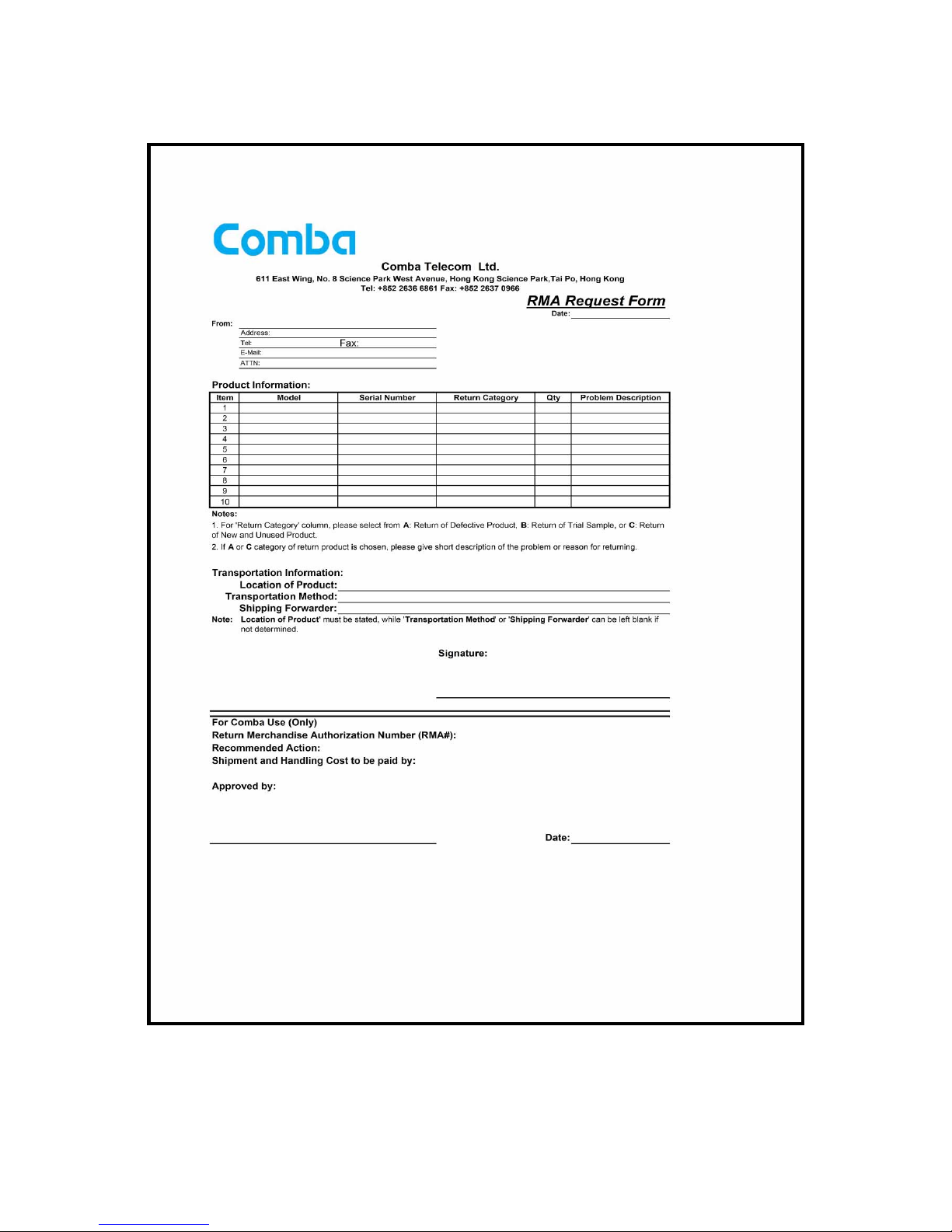
INSTALLATION GUIDE FOR RA-8000
RA-8000 QI Copyright - refer to title page Page 55
ENU Status : 1-0-0
6.3 APPENDIX C: RMA (RETURN MATERIAL AUTHORIZATION) FORM
End of section
End of Document
 Loading...