

Comat SMS Relay, CMS-10F/DC12-48V, CMS-10F/AC110-240V, CMS-10ADF/DC12-48V, CMS-10ACDF/DC12-48V Operating Instructions Manual
Page 1
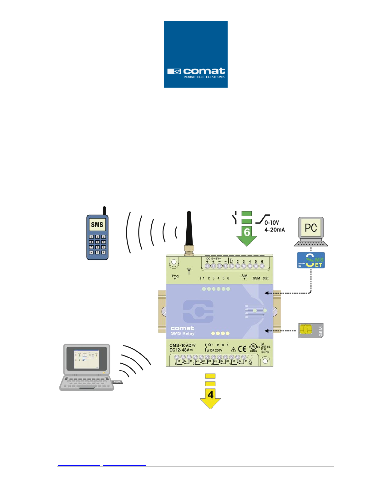
Comat SMS Relay
Comat AG Bernstrasse 4 CH-3076 Worb Tel. +41 (0)31 838 55 77
ba_smsrelay_1010_e
Operating Instructions
Page 2

2
Comat SMS Relay
Operating instructions SMS Relay ba_smsrelay_1010_e
Content
1. SMS Relay Operating Instructions .............................................................................................................................................. 3
1.1 Short description of the CMS Comat Message System SMS Relay ....................................................................................................... 3
1.2 Safety instructions ............................................................................................................................................................................... 3
2. Short instructions ...................................................................................................................................................................... 5
3. Installation details / scope of supply .......................................................................................................................................... 6
3.1 Antenna ............................................................................................................................................................................................... 6
3.2 Wiring .................................................................................................................................................................................................. 7
3.3 Test and Reset Buttons ........................................................................................................................................................................ 8
4. Software .................................................................................................................................................................................... 9
4.1 System requirements ........................................................................................................................................................................... 9
4.2 Software installation .......................................................................................................................................................................... 10
5. Run Mode ................................................................................................................................................................................ 10
5.1 LED status display .............................................................................................................................................................................. 10
5.1.1 GSM-LED ............................................................................................................................................................................................ 10
5.1.2 Status-LED .......................................................................................................................................................................................... 10
5.1.3 Inputs / outputs ................................................................................................................................................................................. 11
5.2 Power failure ...................................................................................................................................................................................... 11
5.3 Diagnose ............................................................................................................................................................................................ 12
5.4 Status request .................................................................................................................................................................................... 13
6. Configuration of the SMS Relay with the „FAST SMS Set™“ Software ........................................................................................ 13
6.1 General .............................................................................................................................................................................................. 13
6.2 Create connection .............................................................................................................................................................................. 13
6.3 Edit telephone book ........................................................................................................................................................................... 14
6.3.1 Phone number ................................................................................................................................................................................... 14
6.3.2 E-Mail address.................................................................................................................................................................................... 14
6.4 Settings .............................................................................................................................................................................................. 15
6.4.1 Device types ....................................................................................................................................................................................... 16
6.4.2 Automatic provider search ................................................................................................................................................................. 17
6.4.3 Manual provider search ..................................................................................................................................................................... 17
6.4.4 SMS Relay identification .................................................................................................................................................................... 17
6.4.5 Activate remote access ...................................................................................................................................................................... 17
6.4.6 Enable local authentication ................................................................................................................................................................ 18
6.5 Status messages ................................................................................................................................................................................. 18
6.6 Input configuration ............................................................................................................................................................................ 19
6.6.1 General .............................................................................................................................................................................................. 19
6.6.2 Digital inputs (CMS-10F/AC110-240V and CMS-10F/DC12-48V) ........................................................................................................ 19
6.6.2.1 Parallel message handling .................................................................................................................................................................. 20
6.6.2.2 Time delayed message for input ON .................................................................................................................................................. 21
6.6.2.3 Time delayed message for output OFF .............................................................................................................................................. 21
6.6.3 Analogue inputs (CMS-10ADF/DC12-48V and CMS-10ACDF/DC12-48V) ........................................................................................... 21
6.6.3.1 Scaling and units ................................................................................................................................................................................ 22
6.6.3.2 Messages ........................................................................................................................................................................................... 22
6.6.3.2 Messages ........................................................................................................................................................................................... 23
6.6.3.3 Message delay ................................................................................................................................................................................... 26
6.6.3.4 Message block.................................................................................................................................................................................... 26
6.7 Output configuration ......................................................................................................................................................................... 27
6.7.1 General .............................................................................................................................................................................................. 27
6.7.2 Timer function ................................................................................................................................................................................... 28
6.7.3 CALL-IN function ................................................................................................................................................................................ 28
7. Remote Access......................................................................................................................................................................... 28
7.1 General .............................................................................................................................................................................................. 28
7.2 Configuration of Remote Access ........................................................................................................................................................ 29
7.3 Connection establishment ................................................................................................................................................................. 30
7.4 I/O status remote request.................................................................................................................................................................. 32
7.4.1 Digital inputs ...................................................................................................................................................................................... 33
7.4.2 Analogue inputs ................................................................................................................................................................................. 33
7.4.3 Outputs .............................................................................................................................................................................................. 34
8. Language selection .................................................................................................................................................................. 34
8.1 General .............................................................................................................................................................................................. 34
9. Technical items ........................................................................................................................................................................ 35
9.1 Dimension .......................................................................................................................................................................................... 35
9.2 Technical data .................................................................................................................................................................................... 36
9.2.1 CMS-10F ............................................................................................................................................................................................. 36
9.2.2 CMS-10ADF ........................................................................................................................................................................................ 36
9.2.3 CMS-10ACDF ...................................................................................................................................................................................... 36
10. Ordering information ............................................................................................................................................................... 37
11. Notes ....................................................................................................................................................................................... 38
12. Overview of your devices and phone numbers ......................................................................................................................... 40
Page 3
3
Comat SMS Relay
Operating instructions SMS Relay ba_smsrelay_1010_e
1. SMS Relay Operating Instructions
1.1 Short description of the CMS Comat Message System SMS Relay
The Comat CMS-10 SMS relay is a remote control and messaging system. It has six inputs
which can be used as analogue or digital inputs and four outputs with change over contacts.
All the inputs can be monitored by SMS (Short Message System). At the same time, the
outputs are controlled and activated with SMS messages via a mobile telephone network*
(SIM card determines the provider).
The device’s own phone book saves up to 50 mobile phone numbers and names of message
receivers.
Each status change on one of the inputs sends a pre-defined message by SMS to the
assigned max. 5 different receivers. The receivers are processed cyclically one by one,
according to the selected sequence. The outputs can be switched ON and OFF with predefined messages by SMS. In order to obtain an overview of the present status of all in- and
outputs and with that in generally of the condition of the entire installation, the input and
output status can also be questioned and retrieved by SMS. The relay outputs can be linked
to a „timer function“ and can be switched time dependant for a preset time.
With the password option, unauthorized remote access to the SMS Relay by a third party is
avoided.
The SMS relay sends out a message at regular intervals as for example in case of a power
loss, whereby the SMS relay is able to send a last warning message before it shuts down. If
the power is restored, the CMS-10 will announce its operational status again with a new
message. All input and output status can be attached to each message. All these options can
of course be made active or inactive as required.
The programming of the SMS Relay is carried out with the FAST SMS Set™ configuration
software provided together with the device. All the settings can be configured very easy and
without special knowledge of any programming language.
With the implemented remote maintenance tool there is a possibility to maintain the SMS
Relay and to modify the configuration over a GSM connection (requirements: GSM modem,
CMS-10F or CMS-10ADF, „FAST SMS Set™“ from version 3.0).
*GSM network: 850MHz, 900MHz, 1800MHz, 1900MHz (quad-band GSM module inside)
1.2 Safety instructions
WARNING
WARNING
WARNING
The electrical installation of the SMS relay must be carried out by a
professional person
Please read the complete operating instructions before installation and
commissioning!
Injuries and or damages cannot be excluded if this warnings are neglected
This device is not suitable for monitoring sensitive installations or time
critical processes. GSM network failure or power interruptions cannot
guarantee a secure monitoring.
This device shall not be used in explosive endangered environment or close
to medical appliances
Page 4
4
Comat SMS Relay
Operating instructions SMS Relay ba_smsrelay_1010_e
1.3 Application examples
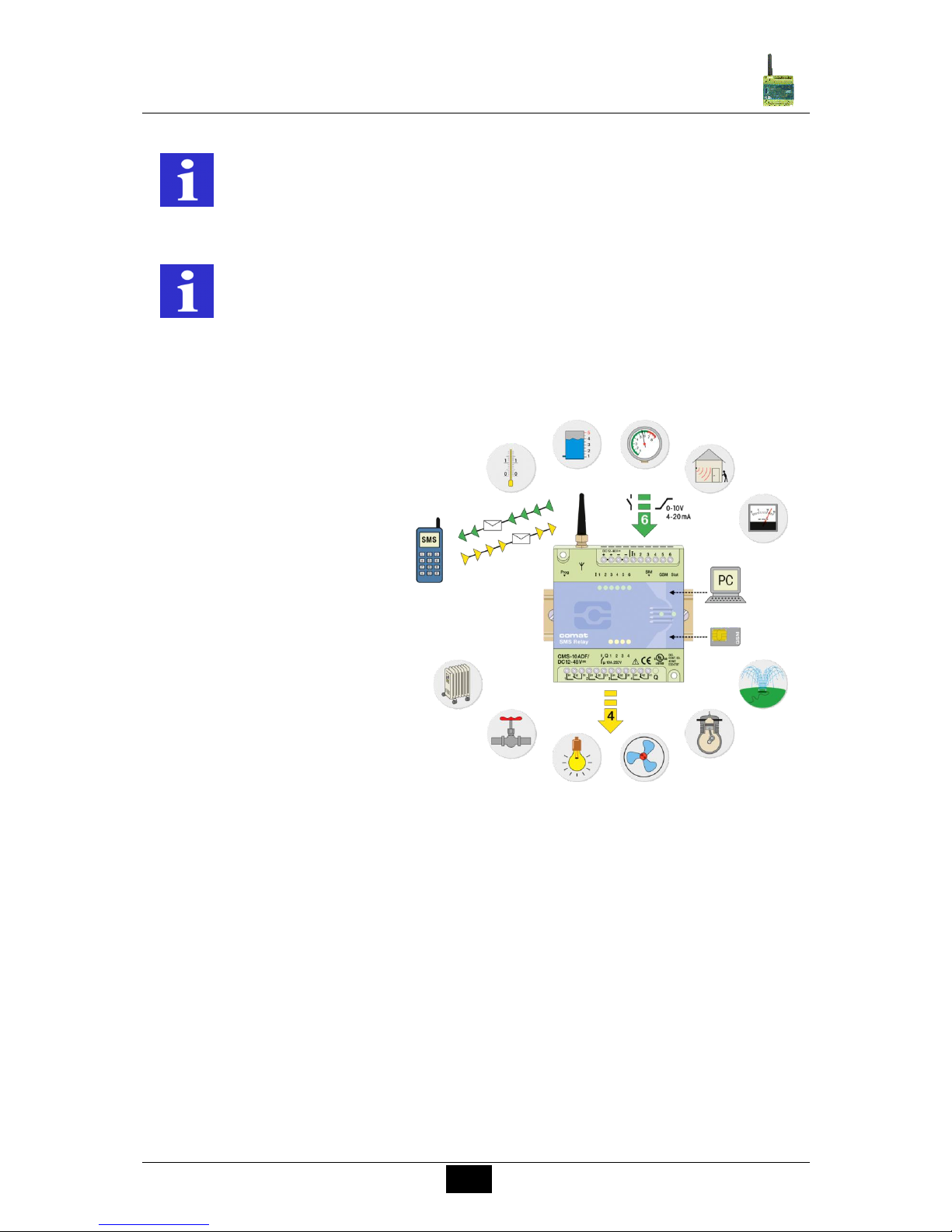
Heating control
Pump control
Irrigation installations
Alarm transmission
Level monitoring
Temperature monitoring
Pressure monitoring
Valve control
Voltage monitoring
REMARK
REMARK
The individual responsibility for protecting the SIM card against abuse lies
solely with the card owner.
The use of a prepaid SIM card is possible. It is recommended to use a SIM
card with subscription. This avoids possible credit balance problems.
Comat AG does not accept any liability for possible damage to persons,
buildings and/or machines, which occur due to incorrect use or from not
following the instructions or abusing the device. Comat AG cannot accept
any responsibility for the application and use of the SMS relay. In particular
Comat AG cannot guarantee the connection security with the mobile
network.
Page 5
5
Comat SMS Relay
Operating instructions SMS Relay ba_smsrelay_1010_e
2. Short instructions
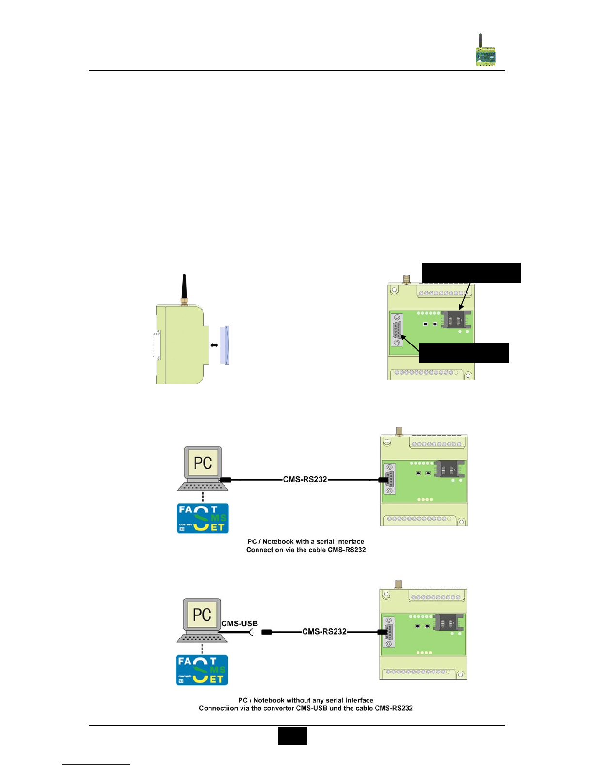
1. The SMS Relay must be separated from the power supply.
2. Place the SIM card into the card holder
3. Connect the RS232 interface of your PC or Notebook with the programming
interface of the SMS Relay. Use the programming cable.
Instruction for the USB converter
In case that there is no RS232 interface connection on the PC or Notebook, an
RS232 interface connection can be generated with a USB converter (e.g. CMSUSB).
For that purpose the USB converter is plugged into a free USB-Port on the
PC/Notebook. For perfect functioning of the interface converter, the driver
software has to be loaded from the included CD-ROM beforehand. After
successful installation, the RS232 programming cable can be connected to the
USB converter and the SMS Relay.
Remove cover
SIM-Card, RS232-Interface
SIM-Card holder
RS232 Interface
Page 6
6
Comat SMS Relay
Operating instructions SMS Relay ba_smsrelay_1010_e
4. Connect the power supply to the SMS Relay. Obey connection diagram
5. As soon as the SMS Relay is ready (after approx. 100 sec), Status-LED & GSMLED are flashing regularly in a cycle of 1 second. Start the programming software
FAST SMS Set™
6. Select your prepared file or create a new file with your configuration. Please set
the correct PIN code (Very important to set correct PIN code, otherwise the SIM
card may block).
7. Select a free COM port (Menu Option – Communication Settings)
8. In menu “Option – Write” download the file to the SMS Relay ( download)
9. Wait until the SMS Relay is ready again (after approx. 100 sec)
10. Set the time and the date (Menu Option – Set date and time)
3. Installation details / scope of supply
3.1 Antenna
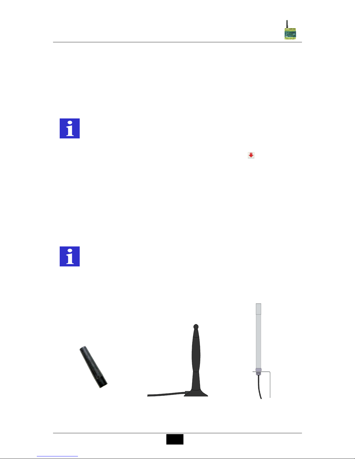
The SMS Relay comes together with the CMS-ANT small device antenna. The location of
installation must be taken into account and the right antenna has to be selected to ensure
reliable connection with the network.
For that purpose, the CMS-ANT-MAG/2.5M antenna with magnetic feet or the CMS-ANTSPEZ/5M external signal antenna provide a much better result. Please take this into account
when ordering. The signal strength may be checked beforehand with a cell phone. Our
product specialists will be glad to answer any questions or to give further advice.
CMS-ANT
CMS-ANT-MAG/2.5M
CMS-ANT-SPEZ/5M
REMARK
Enter correct PIN number of SIM card. This is absolute necessary for the
first commissioning of the installation! The SIM-Card maybe locked without
correct PIN-Code.
REMARK
The CMS-ANT small device antenna is not suitable for installation inside a
control panel (shielding).
Page 7
7
Comat SMS Relay
Operating instructions SMS Relay ba_smsrelay_1010_e
3.2 Wiring
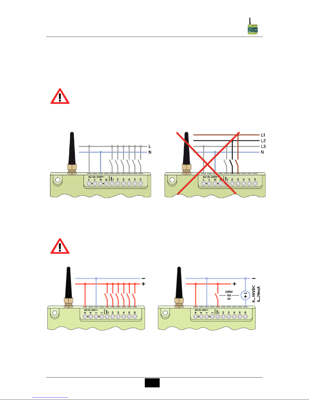
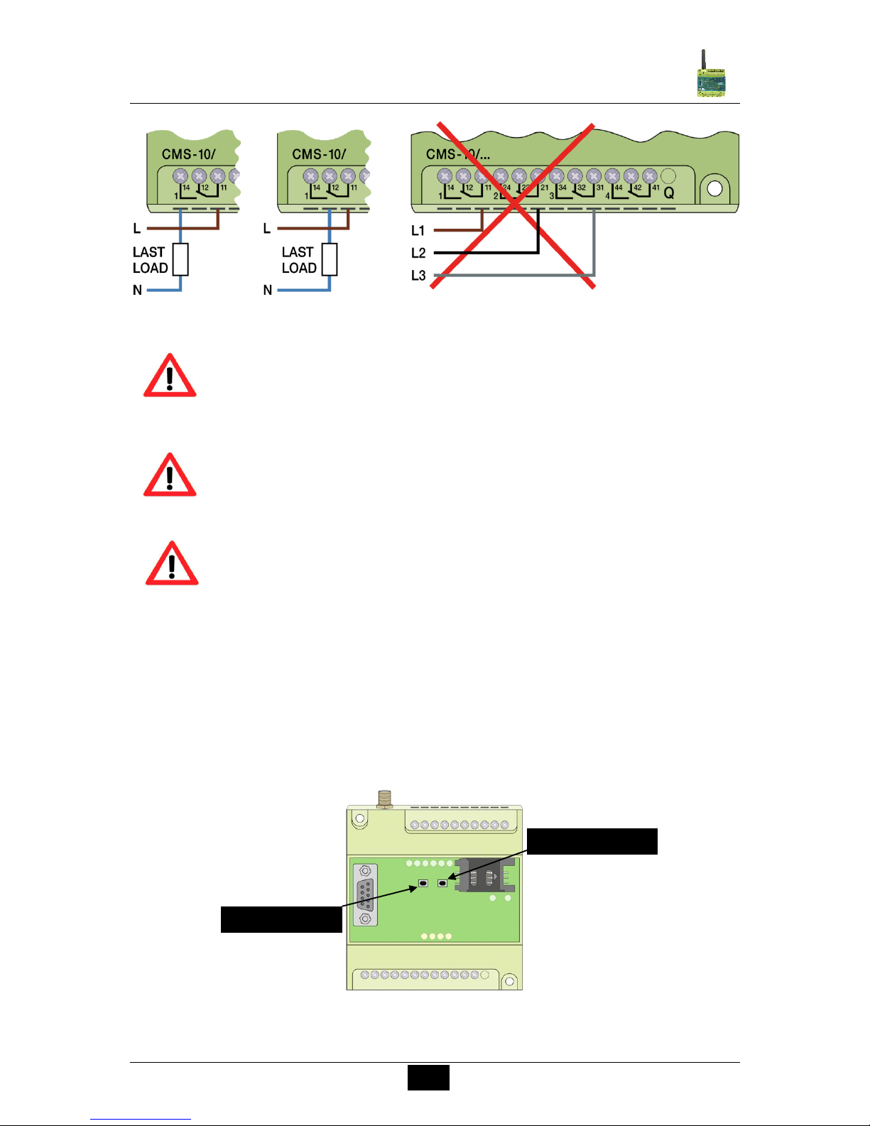
When connecting to the 230VAC mains it is absolutely necessary to ensure that the power
supply and the inputs power supply originate from the same phase i.e. a voltage above
240VAC must be avoided on the device. The SMS relay is isolation protected and does not
need grounding. The SMS relay must be connected according to the following schematic:
Connection CMS-10F/AC110-240V
Digital inputs
Connection CMS-10F/DC12-48V
Digital inputs
Connection CMS-10A(C)DF/DC12-48V
Analog or digital inputs as selected
(configuration with programming software)
WARNING
The electrical installation of the SMS relay must be carried out by a
professional person
Please read the complete operating instructions before installation and
commissioning!
Injuries and or damages cannot be excluded if this warnings are neglected
WARNING
When connecting to the 230V AC supply, please absolutely obey that the
power supply and there inputs are from the same phase.
Voltages above 230V AC on the device are not allowed.
Page 8
8
Comat SMS Relay
Operating instructions SMS Relay ba_smsrelay_1010_e
3.3 Test and Reset Buttons
TEST Button (right button from front view)
If the TEST button is pushed for more than 5 seconds, a test message will be sent.
RESET Button (left button from front view)
All relays outputs are reset to the home position if the button is pushed for minimum 15
secs.. That means for the first change over contact: 12-14 open / 12-13 closed.
The characteristic of all change over contacts is the same.
Test and Reset Buttons
WARNING
WARNING
WARNING
When connecting to the 230V AC supply, please absolutely obey that the
power supply and there Inputs are from the same phase.
Voltages above 230V AC on the device are not allowed
Installation and disconnection of the device only if de-energized.
All applicable regulations and standards have to be obeyed for the
installation of the device. The installation must be executed by a
professional.
TEST-BUTTON
RESET-Button
Page 9
9
Comat SMS Relay
Operating instructions SMS Relay ba_smsrelay_1010_e
4. Software
4.1 System requirements
The „FAST SMS Set“™ configuration software runs on the current Microsoft operating
systems. The following minimum system requirements must be met in order that the software
functions properly:
Operating system:
Windows 2000
Windows XP
Windows Vista
Windows 7
CPU computer capacity:
Pentium II / 166MHz
Recommended: Pentium III / 800MHz
RAM:
256MB (Windows XP)
Hard disc storage capacity available
40MB
Programming interface:
RS232
USB (with USB-RS232 interface converter e.g. CMS-USB)
*Screen resolution
Minimal: 1024 x 768 pixels
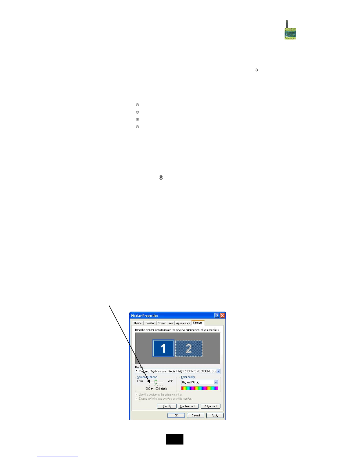
*PLEASE NOTE:
If the screen resolution is too low, the window of the programming software will
not be displayed in the normal size. That means some tabs or buttons would
be outside the screen window and therefore invisible. To avoid this, change
the screen resolution of your computer system. Select “Start” – “System
controls” – “Display” and then the register “Settings”. Please set the screen
resolution to 1024 x 768 pixels in minimum.
Page 10

10
Comat SMS Relay
Operating instructions SMS Relay ba_smsrelay_1010_e
4.2 Software installation
Once the CD-ROM is inserted into the CD drive, the installation menu starts automatically.
If this is not the case, then the CD-ROM can be started by double clicking „Start“ in the
Windows®Explorer. In case that there should be no CD-ROM available, the software is
available for free download from the website of COMAT AG. Please visit www.comat.ch.
The installation menu is available in different languages. Please choose the required
language. Please follow the set-up programming instructions during installation.
The SMS relay starts up automatically once power has been supplied. If the signal is strong
enough, the device will register itself in the GSM network (according to the SIM card settings,
depending on provider). Both LED will display the actual status of the device as well as the
network status (→ chap.5).
5. Run Mode
5.1 LED status display
The SMS relay has two LEDs, the GSM LED und the status LED. Both LEDs can be seen
from the outside and are located below the cover. The following statuses are indicated:
5.1.1 GSM-LED
- Flashing regularly (every second) Module is not registered in the
GSM network.
- Short flashing (approx. every three seconds) Module is registered and ready for
data communication
- Irregular flashing Data are transmitted (SMS)
5.1.2 Status-LED
- Dark LED Device does not run
- Intermittent flashing (irregular) Device starts up
- Short flashing (like GSM LED, approx. every 3s) 1x Device runs, everything OK
- Short flashing (like GSM LED, approx. every 3s) 2x No credit left
- Short flashing (like GSM LED, approx. every 3s) 3x Clock not adjusted
- Flashing regularly (every second) 1x Module in initial state
- flashing regularly (every second) 2x Configuration error / SIM blocked
- Flashing regularly (every second) 3x Communication error
Further information’s and solutions please refer to “5.3 Diagnose”
Page 11
11
Comat SMS Relay
Operating instructions SMS Relay ba_smsrelay_1010_e
5.1.3 Inputs / outputs
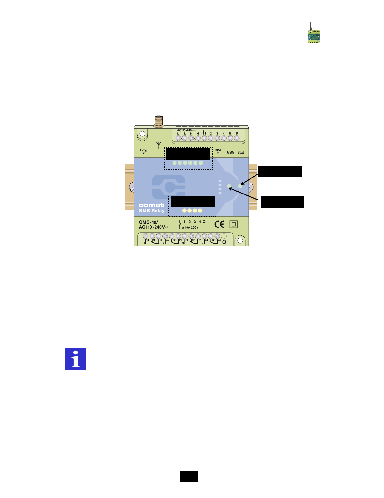
Each input and output status is displayed with individual LED’s.
These LED are designated as follows:
Inputs I1, I2, I3, I4, I5, I6 (LED lighting = Input is switched on)
Outputs Q1, Q2, Q3, Q4 (LED lighting = Output is switched on)
5.2 Power failure
Short power supply failures (t < 1s) are tolerated and do not change the module status.
Longer power failures (t > 1s) are registered and can trigger a last SMS alarm message
(depending on the set mode) before the device shuts down. The device restarts
automatically after the power supply is restored. The registration of the SMS Relay in the
GSM network is restored and the same status of the outputs is initiated as before the power
failure (Memory function).
REMARK
The monostable relays are in their home position during power off. E.g.
contact 11-14 open / contact 11-12 closed.
After power restore, the contacts are in the same position as before the
power failure. (Memory function.)
Status-LED
Inputs
Outputs
GSM-LED
Page 12
12
Comat SMS Relay
Operating instructions SMS Relay ba_smsrelay_1010_e
5.3 Diagnose
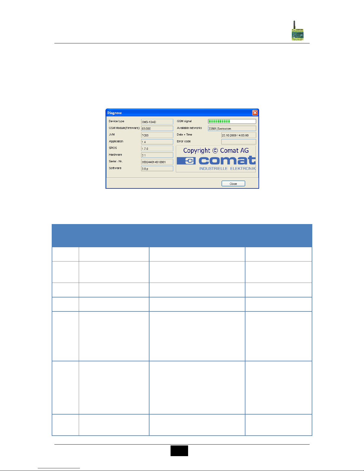
The SMS Relay together with the programming software „FAST SMS Set™“ allows the
display of the actual signal strength. For that function, the SMS Relay has to be connected to
a PC / Notebook with the programming cable. To get to the diagnose function, select Option
– Diagnose from the menu in the programming software. In addition to the signal quality, the
diagnose will display some more information like version numbers, error codes and service
provider.
Diagnose window
Error codes and signification:
Error
codes
Signification
Reason
Remedies
1
No credit
Pre-paid card empty
Load SIM card
2
Time not set
No time set
Configuration -> Set
time
3
no configuration found
no configuration loaded
Load file
4
Configuration error
Incomplete file safe
Repeat file loading
5
Communication error
Relay connection to PC is
interrupted for a short moment
during data transfer. SMS relay
function is however normally
fully maintained. Status LED is
flushing 2*/second
Repeat file loading
1001
SIM card blocked
Wrong Pin code entered 3 times
SIM card must be
inserted into a cellular
(mobile phone) --> to
clear PUK code
--> insert again into
SMS relay
1002
No SIM card
SIM card missing, not correct
inserted or contaminated surface
Insert SIM card
correctly or clean
Page 13

13
Comat SMS Relay
Operating instructions SMS Relay ba_smsrelay_1010_e
5.4 Status request
If the SMS Relay is connected by a cable (CMS-RS232 or CMS-USB with CMS-RS232) the
actual status of the inputs and outputs can be requested. The status can also be requested
by remote maintenance (→ chap.7).
6. Configuration of the SMS T SMS SetSoftware
6.1 General
The SMS Relay is configured and prepared for use with the „FAST SMS Set
™
“
configuration
software. The SMS Relay configuration (telephone book creation, message definitions,
default settings, etc.) can be done on a PC and saved in a respective file without connection
to the device. In order to do this, the software is started, a new or existing file opened and
edited. The saved file needs to be downloaded to the SMS Relay with the CMS-RS232
programming cable. In offline mode, the diagnostic functions are not active and can only be
accessed once the SMS Relay is connected with the RS232 serial interface cable to the PC.
With the implemented remote maintenance tool there is a possibility to maintain the SMS
Relay and to modify the configuration over a GSM connection (requirements: GSM modem,
CMS-10F, CMS-10ADF or CMS-10ACDF, FAST SMS SetTM from version 3.0). The
procedure to setup the remote access is explained in chapter 7.
6.2 Create connection
Cut off the power supply of the SMS Relay
Insert the SIM card
Connect the RS232 interface of your PC or Notebook with the SMS Relay programming
interface using the CMS-RS232 programming cable. If your PC or Notebook does not
have an RS232 interface connection then use a CMS-USB interface converter. With this
converter the programming cable can be directly connected to one of the computer’s
USB slots.
Connect power supply to the SMS Relay
As soon as the Status-LED of the SMS Relay flushes in a cycle off 1 second, the
software can be started.
Choose a saved file or create a new one.
For transmission, choose the required COM port of your PC. Select menu „Option –
Communication settings – Available COM ports“.
Everything is now set up to download the prepared configuration file to the device.
Page 14
14
Comat SMS Relay
Operating instructions SMS Relay ba_smsrelay_1010_e
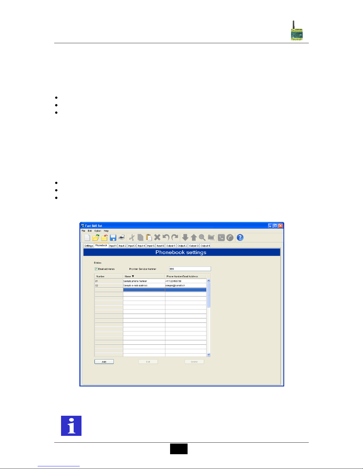
6.3 Edit telephone book
The software offers the possibility to register and manage up to 50 telephone numbers or
email addresses. Administration of the telephone book as described below:
6.3.1 Phone number
Add – register of a new phone number
Edit – editing of an already existing entry
Delete – deleting of an existing entry
Please enter the phone number in international format (i.e. with country code and prefix), e.g.
+41793333333. (+41 Switzerland; +49 Germany, +31 Netherland, etc)
6.3.2 E-Mail address
Activate first the e-mail function in the field Activate e-mail and enter the provider service
number. Register now the e-mail addresses as follows:
Add – register of a new e-mail address
Edit – editing of an already existing entry
Delete – deleting of an existing entry
Please enter the addresses in the format [email protected]!
Phonebook entry
REMARK
Not all special characters can be used for SMS messages.
The characters are recognized by the programming software and displayed
in an error window. Subsequently, the respective characters have to be
erased.
Page 15
15
Comat SMS Relay
Operating instructions SMS Relay ba_smsrelay_1010_e
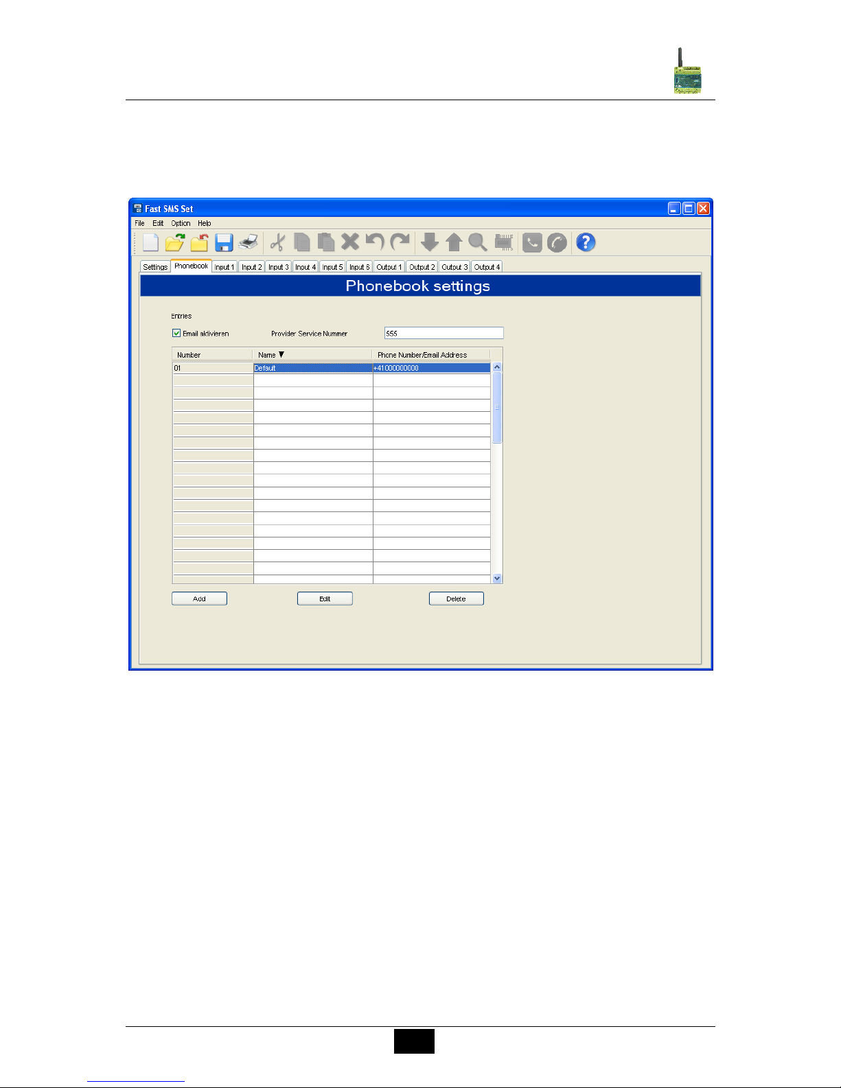
In the data field „Name“, the list can be sorted in ascending or descending alphabetical order.
The sorting does not influence entries which have already been used.
The default entry shall be replaced with an own entry!
SMS Relay telephone book editor
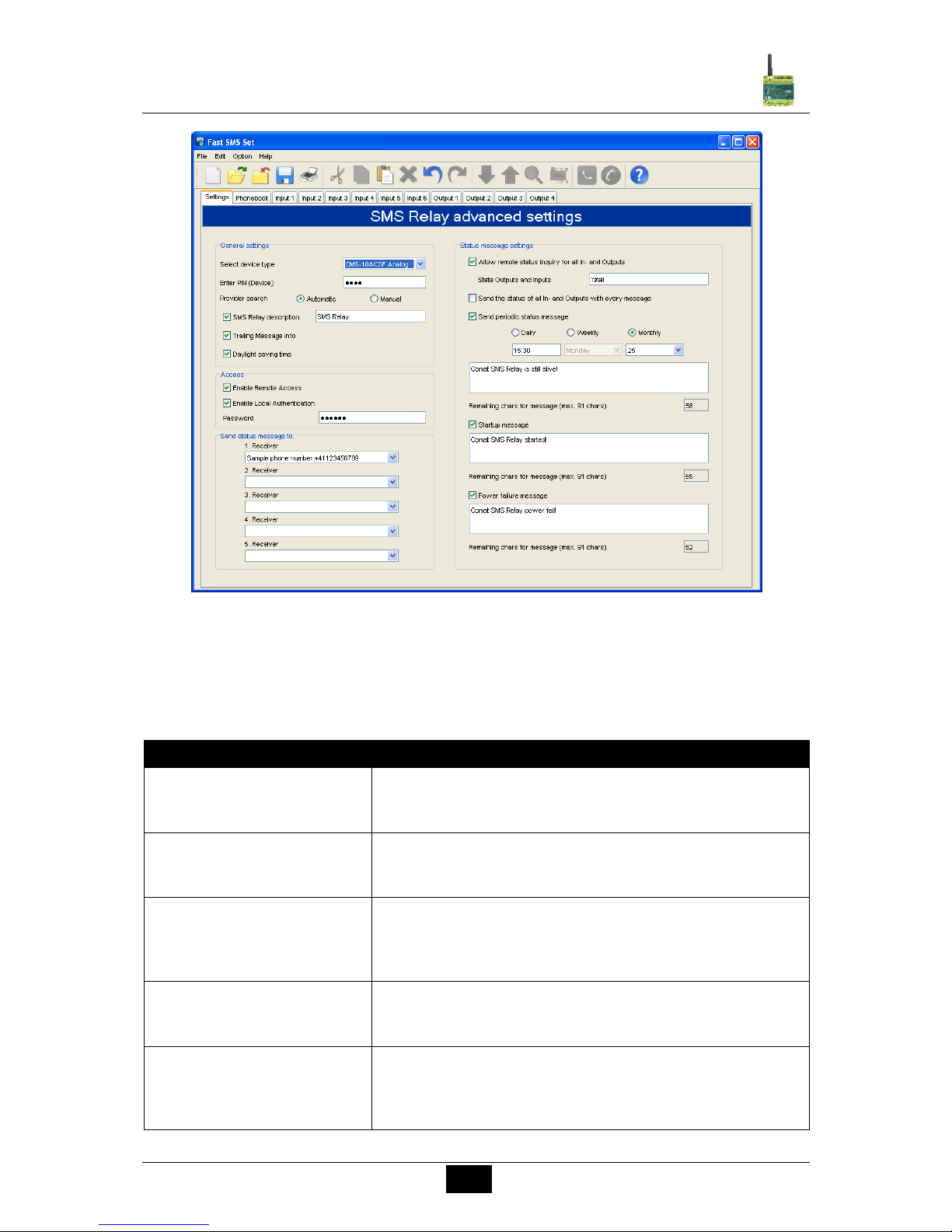
6.4 Settings
The default settings for SMS transmission contain important general data which help to
identify the device. The SIM card can be protected with a PIN code just like for normal cell
phone use. The PIN request is activated and the PIN code is inputted in the required field.
This concerns PIN1. Further information can be obtained from the SIM card manual.
Likewise the process of unblocking the SIM card after three incorrect inputs of PIN1 is
described in the SIM manual. In order to do this, the SIM card must be removed from the
SMS Relay and inserted into a mobile phone. Now the card can be unblocked according to
the details of the network providers.
Page 16
16
Comat SMS Relay
Operating instructions SMS Relay ba_smsrelay_1010_e
SMS Relay Settings
6.4.1 Device types
Depending on the device type, the correct type has to be selected. The selection has an
influence on the configuration of the inputs and outputs. It is however possible to correct the
selected type at any time. The following types are available:
Type
Description
CMS-10 digital
substituted by CMS-10F
This type has only digital inputs
CMS-10/AC110-240V
CMS-10/DC12-48V
CMS-10AD analogue
substituted by CMS-10ADF
For this type the inputs can be used to work as analogue
or digital inputs
CMS-10AD/DC12-48V
CMS-10F digital
This type has only digital inputs. Remote access
integrated
CMS-10F/AC110-240V
CMS-10F/DC12-48V
CMS-10ADF analogue
This type allows using the inputs as analogue or digital
inputs. Remote access integrated. Input signal 0-10V.
CMS-10ADF/DC12-48V
CMS-10ACDF analogue
This type allows using 4 inputs as analogue 0-10V or
digital inputs. Additional this device has 2 current inputs 420mA (I5 and I6). Remote access integrated.
CMS-10ACDF/DC12-48V
Page 17
17
Comat SMS Relay
Operating instructions SMS Relay ba_smsrelay_1010_e
6.4.2 Automatic provider search
The automatic provider selection depends on the SIM card inserted into the SMS Relay. The
provider details and access of the SIM card are adapted. Basically, the provider is
preassigned when the SIM card is purchased. With the „Automatic“ setting, the network
provider is automatically searched and logged. That is useful if the card is used in the home
network. Other GSM networks can be accessed abroad with the same SIM card according to
the roaming contracts.
6.4.3 Manual provider search
For manual provider searches, the available GSM networks are scanned several times. The
results of this search are displayed with a list of networks. A mouse click on „Search“
displays the available networks. The desired network can now be chosen.
The SMS service centre number can be taken from the SIM card documentation. Normally
this number is already saved on the SIM card. The number depends on the GSM provider. In
the „SMS Relay description“ field, a name for the SMS relay can be entered. All outgoing
messages from this SMS Relay are provided with this identification text. The available
number of characters for a message is reduced according to the number of characters
already used for the identification name. The actual number of available characters is
displayed.
6.4.4 SMS Relay identification
The SMS Relay can be described with a name or a description. All messages sent from this
SMS Relay receive the name as entered in the field “SMS Relay description”. The SMS
Relay identification can be deactivated so that the messages can be sent without this
identification (this function is only available in devices with firmware version FW > 5.0).
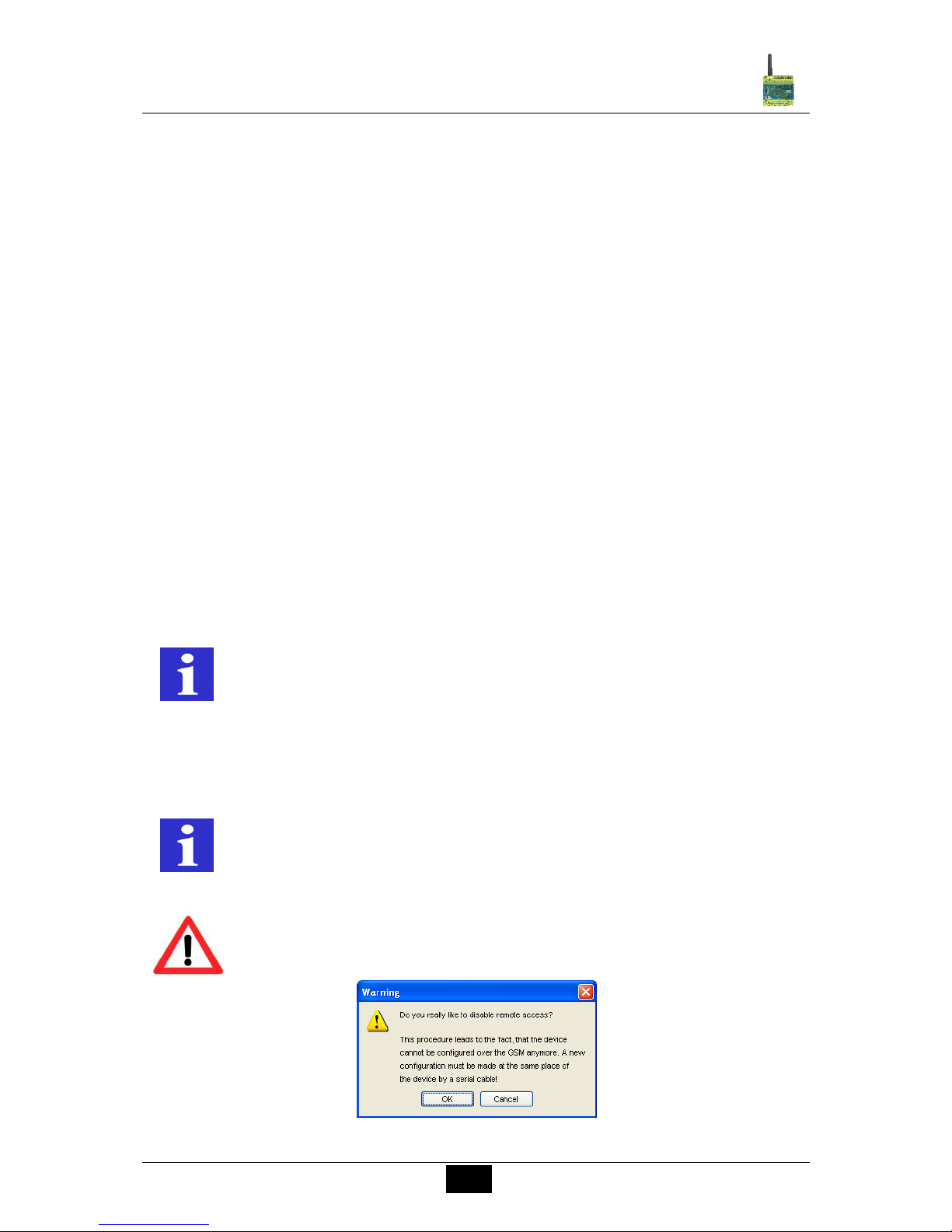
6.4.5 Activate remote access
The SMS Relay can be described with a name or a description. All messages sent from this
SMS Relay receive the name as entered in the field “SMS Relay description”.
Warning disable remote access
REMARK
The display of special characters in the GSM network can cause problems.
Please use only text characters and figures. The programming software
identifies special characters and an error messages will occur.
REMARK
Remote Access has to be set up by a conventional serial cable connection
(RS232) with a PC/notebook for the first time.
WARNING
The remote access can be deactivated in the remote access mode. After
deactivating the remote access, the device can not be reached and
configured over the mobile network anymore. Remote Access has to be set
up by a conventional serial cable connection (RS232) with a PC/notebook.
Page 18
18
Comat SMS Relay
Operating instructions SMS Relay ba_smsrelay_1010_e
6.4.6 Enable local authentication
The local access can be protected by a password. The password is the same as for the
remote access.
6.5 Status messages
The receiver of the status messages can be chosen from the telephone book. In order to do
this click with the mouse pointer onto the expand arrow and select the required entry.
The SMS relay can send the following status messages:
Remote enquiry of all inputs and outputs
The device offers the possibility to interrogate all input and output states by SMS. A code
word is therefore sent by SMS to the device. The code word can be individually created.
The default code word is: ?#all
The answer is sent to the same phone number from which the correct code word was
received (phone number identification). The states of the inputs and outputs are displayed as
follows in the SMS message:
I:001001 Inputs 1 to 6 0 = OFF / 1 = ON
O:0101 Outputs 1 to 4 0 = OFF / 1 = ON
If there are inputs configured as analogue inputs, the SMS Relay sends the analogue value
including the selected unit after the status of all the digital inputs. The analogue inputs will be
substituted with “-“. In the following example, with the inputs I2 and I5 configured as
analogue inputs, the status message looks as follows:
I: 0-10-1 O:0101 21.2m3/h,126lt
I:0-10-1 Inputs 1 to 6 0 = OFF / 1 = ON / - = analogue
O:0101 Outputs 1 to 4 0 = OFF / 1 = ON
Attach Status of all inputs and outputs with each message
A status message of all inputs and outputs is attached to each message.
(Firmware Version 2.8 and Software 1.3.0)
Message at the start
A message for each start up (switching on / return of power) of the SMS relay is sent
(According to the phone number assigned to the event). The message contents can be
edited.
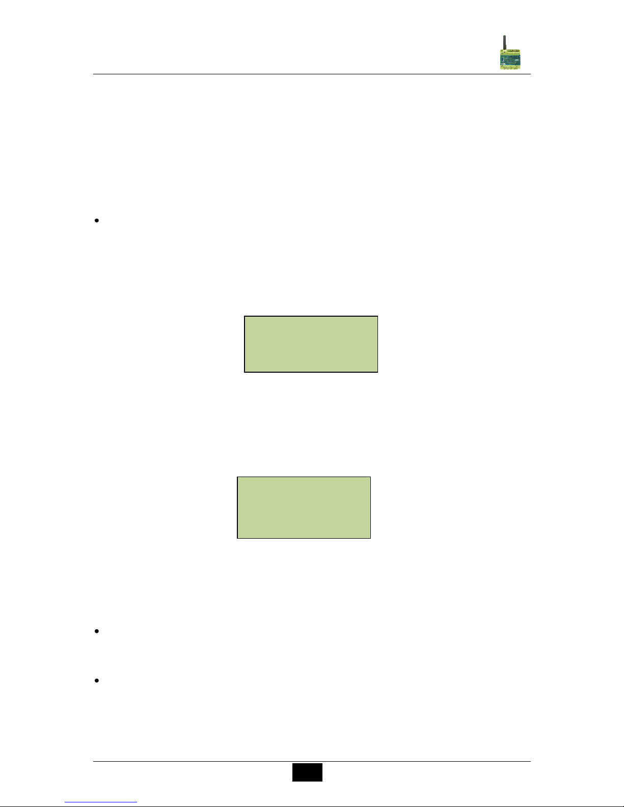
SMS Relay I=001001 Q=0101
V1.4.5 SPIOS=1.7.0 HW=2.1
SN=358244014610861
16.09.2009 15:38
SMS Relay I=0-00-0 Q=0000
21.3m3/h,126lt V1.4.5
SPIOS=1.7.0 HW=2.1
SN=358244014610861
16.09.2009 15:38
Page 19
19
Comat SMS Relay
Operating instructions SMS Relay ba_smsrelay_1010_e
Messages in case of power failure
In case of voltage failure, the SMS relay sends a last message to the assigned receiver
No.1 to 5 of the status messages. The message contents can be edited.
Periodical message
The periodic message provides information of the device’s current status and is sent
periodically. The message can be sent daily (time), weekly (time, weekday) or monthly
(time, date). The message text can be edited. It is for checking functionality or operation
confirmation.
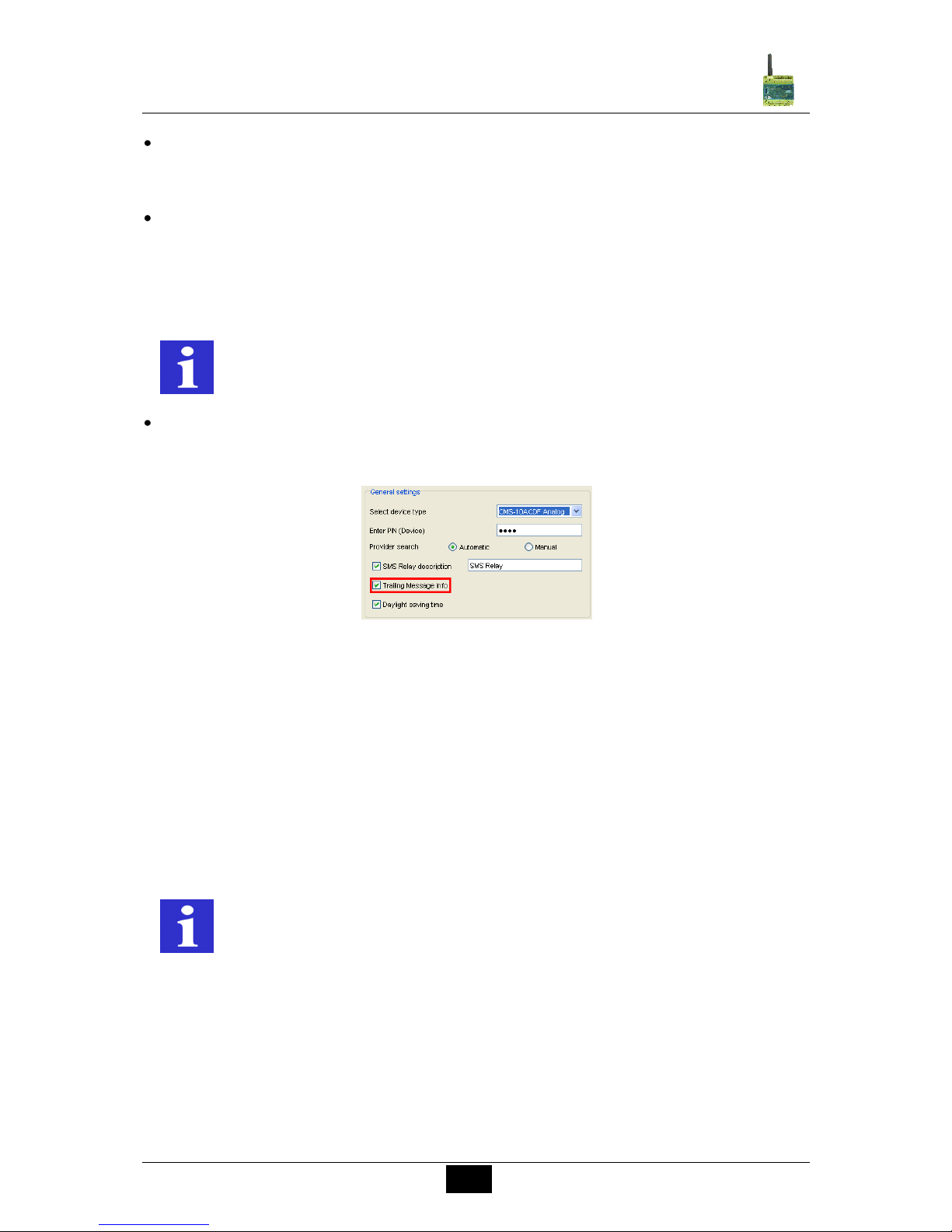
Trailing information
The trailing information of each message (date, time, remaining balance) can be
activated or deactivated in the field Trailing Message Info located under tab Settings.
Trailing information
6.6 Input configuration
6.6.1 General
The SMS Relay has 6 inputs. Depending of the device type, all this inputs can be used as
digital inputs only (CMS-10F/AC110-240V and CMS-10F/DC12-48V) or as digital /
analogue inputs (CMS-10ADF/DC12-48V and CMS-10ACDF/DC12-48V).
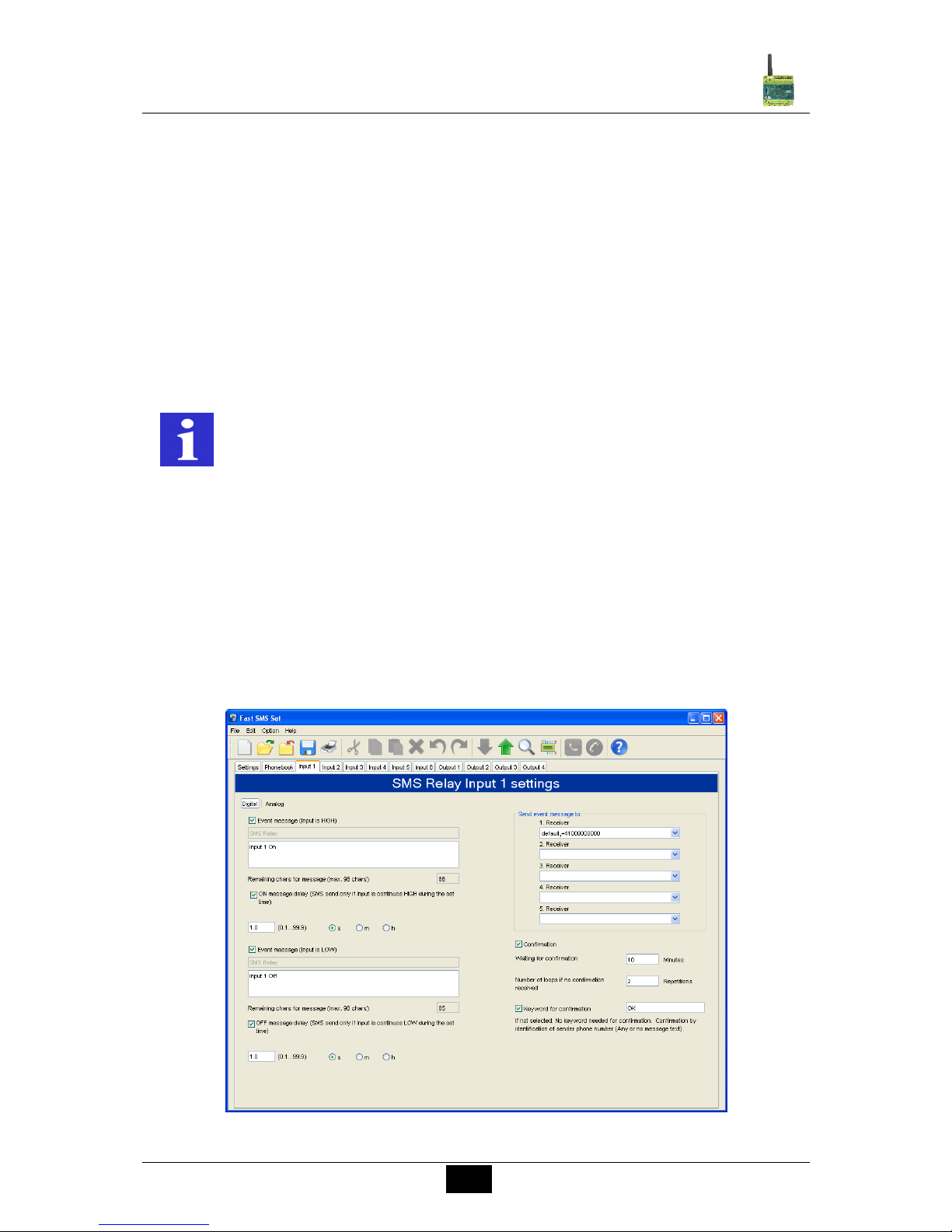
6.6.2 Digital inputs (CMS-10F/AC110-240V and CMS-10F/DC12-48V)
Each one of these inputs can activate an SMS message to a predefined telephone number
either in case of HIGH or LOW input signal (up to 5 various numbers).
Basically two events can trigger an SMS message: the change from LOW-to-HIGH and the
inverse, the change from HIGH-to-LOW. One or both events can be configured to activate a
message. A separate text message can be entered for each event. For details refer to
6.6.2.2 and 6.6.2.3
REMARK
The display of special characters in the GSM network can cause problems.
Please use only text characters and numbers. The programming software
identifies special characters and an error messages will occur.
REMARK
Please mind every input needs at least one phone number in his list. It
doesn’t matter if the input is connected or not or if the status messages are
set inactive. If the receiver field is empty, the software can’t save the file or
the file can’t be downloaded to the SMS Relay.
Page 20
20
Comat SMS Relay
Operating instructions SMS Relay ba_smsrelay_1010_e
With confirmation function activated:
If the SMS Relay does not receive an acknowledgement SMS within a certain preset time
from the receiver, the event message will be sent to the next receiver. This means that the
device runs through the 5 allocated receiver numbers and restarts afterwards with the first
number again (The number of running loops can be pre-defined). As soon as the device
receives a confirmation from the receivers the process is stopped. If this is not the case, the
message will be sent to the next receiver (after expiry of the preset time).
If the confirmation is inactive, all receivers who are allocated to that event will receive a
message without repetition.
If the confirmation code word is not activated, the phone number identification is carried
out as a security check and it is sufficient to send an empty SMS message to the SMS Relay.
6.6.2.1 Parallel message handling
It may occur that the status of several inputs change at the same time or within the actual
running message cycle. Every input activates its individual message.
Every change of the input status, which triggers an event message, is processed in order of
the appearance. That means that all the messages for every input will be handled individual.
Several events at the same time can trigger different messages at the same time. Example:
The events “pump breakdown” and “over temperature” (two different inputs) appear at the
same time both events are processed individual and both messages will be sent one after
the other.
Digital input configuration
REMARK
The display of special characters in the GSM network can cause problems.
Please use only text characters and figures. The programming software
identifies special characters and an error messages will occur.
Page 21
21
Comat SMS Relay
Operating instructions SMS Relay ba_smsrelay_1010_e
6.6.2.2 Time delayed message for input ON
If there is an input signal, the respective message transmission can be time delayed, i.e. the
SMS relay only sends the pre-defined message after the preset time has elapsed and if the
signal has remained ON constantly during that time. In other words, the input signal is
ignored during the set delay time. Time delays of 0.1 seconds to 99.9 hours are possible.
This time function default must be activated and is to prevent that unstable short signals can
activate numberless identical SMS messages.
6.6.2.3 Time delayed message for output OFF
If an input changes from HIGH to LOW, i.e. there is no longer an input signal, a delayed
message can also be activated here. The SMS relay sends the predefined message after the
preset time has elapsed and if the signal is no longer present respectively the input signal
was constantly OFF during the selected time delay. Time delays of 0.1 seconds to 99.9
hours are possible. This time function must be activated and is to prevent that unstable short
signals as for example of a floating level switch will activate numberless messages.
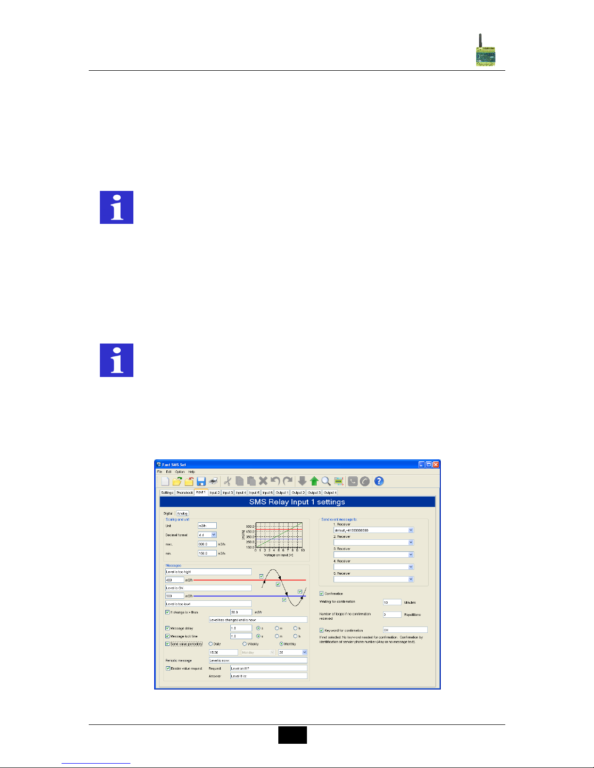
6.6.3 Analogue inputs (CMS-10ADF/DC12-48V and CMS-10ACDF/DC12-48V)
The 6 inputs can be individually configured as digital or analogue inputs. For that purpose
each input has to be predefined as analogue or digital input. The analogue inputs are
designed for a standard 0 … 10V DC or 4 … 20 mA analogue signal. The LSB is 12.5 mV
respectively 20 µA.
Configuration of the analogue inputs
REMARK
It is recommended to use the delay function to avoid that several messages
are sent for the same event.
REMARK
It is recommended to use the delay function to avoid that several messages
are sent for the same event.
Page 22
22
Comat SMS Relay
Operating instructions SMS Relay ba_smsrelay_1010_e
6.6.3.1 Scaling and units
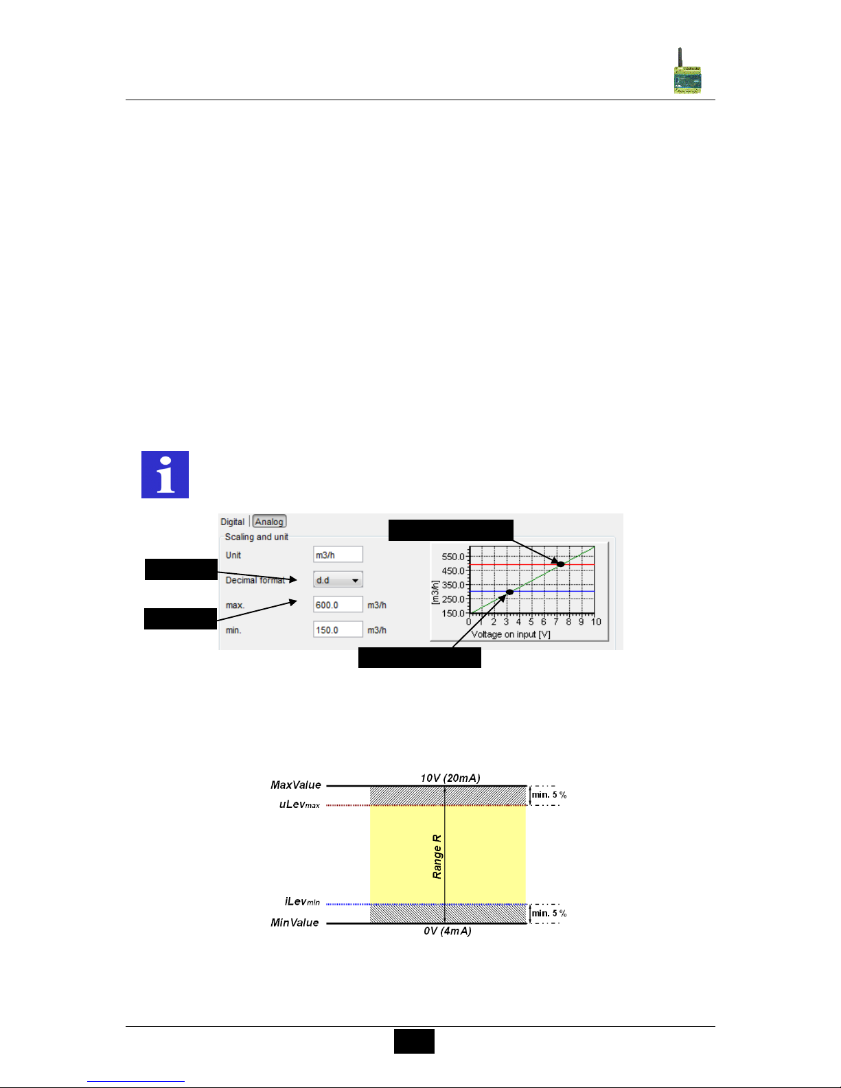
In a first step, the measuring unit and the scale have to be defined. For both end-values 0V
(4mA) and 10V (20 mA), a minimal and a maximum value of the selected unit is assigned.
With this two values, a linear function is interpolated (straight line between 2 points) and
displayed in the configuration window. The linear function is adapted automatically in
accordance to the set values.
The values displayed on the PC screen or transmitted by SMS can be display in different
resolutions:
d integer value, i.e. 5200
d.d one digit after decimal point, i.e. 5200.0
d.dd two digits after decimal point, i.e. 5200.00
d.ddd tree digits after decimal point, i.e. 5200.000
Ten characters are available for the description of the units. This unit will be sent with every
value message following the actual value:
Example of a message: The temperature is 15.5C
Detail: Scaling and unit
6.6.3.2 Messages
The top and the bottom thresholds have to be defined to allow sending of messages.
Description of the range
The value between the max and the min value is the range R. This range has an important
function in the designation of the thresholds.
REMARK
The display of special characters in the GSM network can cause problems.
Please use only text characters and figures. The programming software
identifies special characters and an error messages will occur.
MaxValue
MinValue
Upper Level uLev
max
Lower Level lLev
min
Page 23
23
Comat SMS Relay
Operating instructions SMS Relay ba_smsrelay_1010_e
6.6.3.2 Messages
The top and the bottom thresholds have to be defined to allow sending of messages.
These limiting values depend on the installation which is monitored.
However, certain rules have to be obeyed so that the level values can be recognized in the
scale window.
At first the measuring range has to be calculated. The range is the span between maximum
and minimum values. These 2 values refer to the end values 0…10V respectively 4…20mA
of the analog input signal. The calculated is positive.
│Range R│ = │MaxValue – MinValue│
The maximum Upper Level uLev
max
is calculated as follows:
Deduct 5% of the Max value.
uLev
max
= MaxValue - (│R│ x 0.05)
Inserted values higher then calculated above are corrected automatically by
the software
The minimum Lower Level lLev
min
is calculated as follows:
Add 5% to the Min. value
iLev
min
= MinValue - (│R│ x 0.05)
Inserted values lower then calculated above are corrected automatically by
the software
Example:
Max. value 600m3/h 10V of the analog signal
Min. value 150m3/h 0V of the analog signal
Range R = Max value – Min value = 600m3/h – 150m3/h = 450m3/h
Upper Limit uL = Max. value – B x 0.05 = 600m3/h – (450m3/h x 0.05) = 577.3m3/h
Lower Limilt iL = Min value + B x 0.005^= 150m3/h + (450m3/h x 0.05) = 172.5m3/h
Page 24
24
Comat SMS Relay
Operating instructions SMS Relay ba_smsrelay_1010_e
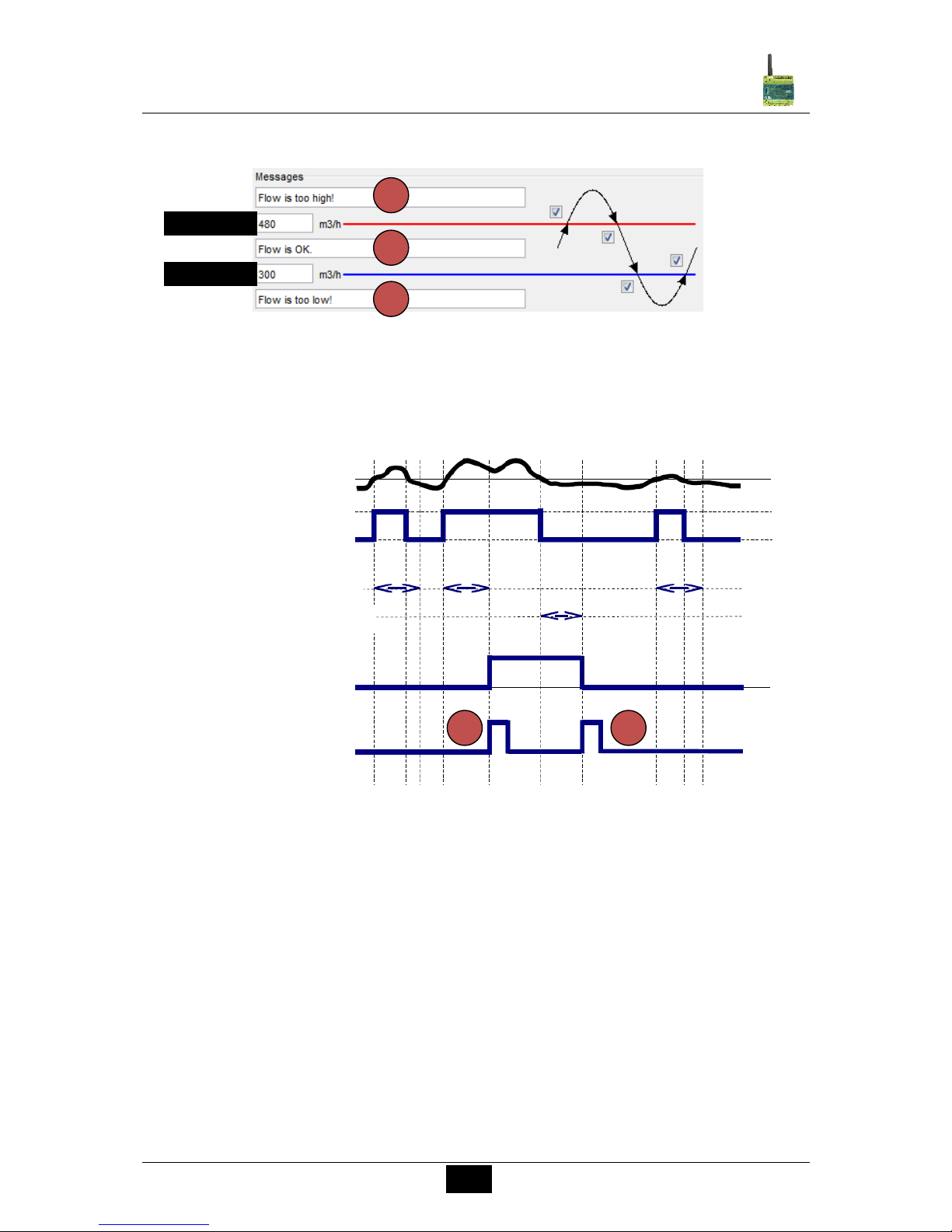
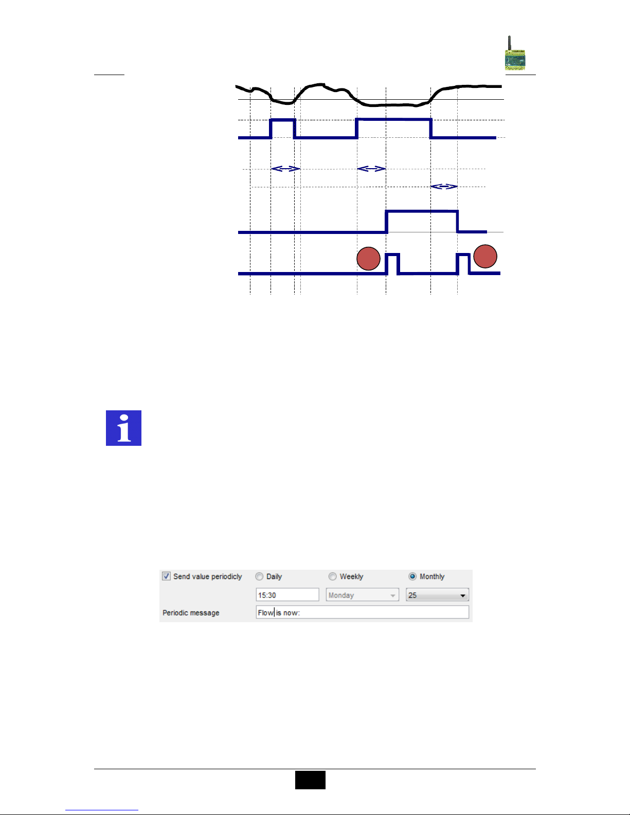
The above example allows monitoring the scenario as seen below:
Threshold messages
The actual measured value is higher than the defined upper limit.
The system is not in its normal status. The upper limit is exceeded. A message is sent (if this
is activated by ). The message text can be freely configured.
Analogue value processing: The measured value is above the upper level.
The actual measured value is between the Upper and the Lower Level.
The installation is in normal status. A message is only sent (if default set) if previously the
measured value was above or below Upper or Lower limit.
On this example the actual measured value is below the set Lower Level
The system is not in its normal status. The value is below the lower limit. A message is sent
(if this is activated by ). The message text can be freely configured.
Upper Limit
Lower Limit
2 1 3
Upper Level
Event (delayed)
Delay time ON
Message lock time ON
Upper Level
Event
SMS message
1
2
Page 25
25
Comat SMS Relay
Operating instructions SMS Relay ba_smsrelay_1010_e
Analogue
A certain difference between the actual value and the last sent value is exceeded
The SMS Relay monitors the analogue value. A message is sent if the difference exceeds a
certain value (if this is activated by ). The message text can be freely configured. The
maximal value for this is 50%.
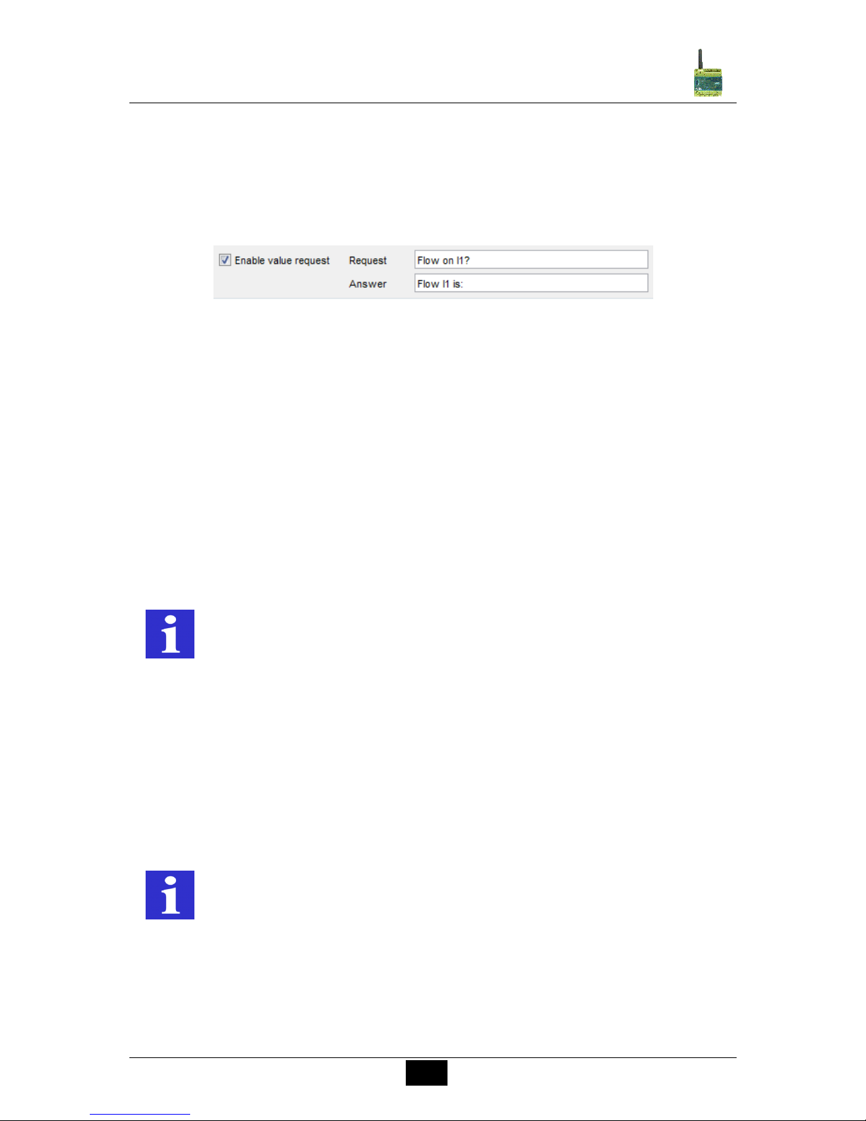
Periodical messages
The actual values can be sent by SMS periodically in intervals of days, weeks or months.
The periodical message is sent to the first receiver. If this message is not confirmed, it will be
forwarded automatically to the next receiver.
All message texts can be freely edited. The measured value and the unit are always
transmitted together with the message text.
A space is inserted automatically between the message text and the value. No space is
inserted between the value and the unit.
Periodical messages
REMARK
Inserted values above that 50% limit are corrected automatically by
the software
Event (delayed)
Delay time ON
Message lock time ON
Lower Level
Event
SMS message
2
3
Page 26
26
Comat SMS Relay
Operating instructions SMS Relay ba_smsrelay_1010_e
Request value
The actual present value can be enquired by SMS. The message text can be freely edited.
To enquire the actual value, a SMS message has to be sent to the device first. This message
text can be edited freely. However, the incoming SMS text must comply fully with the
programmed enquiry text. A space is inserted automatically between the message text and
the value. No space is inserted between the value and the unit.
Request value
Confirmation
If the SMS Relay does not receive a confirmation SMS within a certain preset time from the
receiver, the event message will be sent to the next receiver. This means that the device
runs through the 5 allocated receiver numbers and restarts afterwards with the first number
again (The number of running loops can be pre-defined). As soon as the device receives a
confirmation from the receivers the process is stopped. If this is not the case the message
will be sent to the next receiver (after expiry of the preset time).
If the acknowledgement is inactive, all receivers who are allocated to that event will receive a
message without repetition.
If the confirmation code word is not activated, the phone number identification is carried out
as a security check and it is sufficient to send an empty SMS message to the SMS Relay.
6.6.3.3 Message delay
If the message criteria are reached, the respective message transmission can be time
delayed, i.e. the SMS relay only sends the pre-defined message after the preset time has
elapsed and if the value has remained constantly during that time. In other words, the
measured value is ignored during the set delay time. Time delays of 0.1 seconds to 99.9
hours are possible. This time function default must be activated and is to prevent that
unstable short signals can activate numberless identical SMS messages.
6.6.3.4 Message block
If message criteria are reached, which requires sending of a message, a timer is triggered.
There will be no further message (same messages) sent during that pre-set time.
With that setting it can be avoided that the same status message is sent repeatedly during a
set time (Block time).
REMARK
The display of special characters in the GSM network can cause
problems. Please use only text characters and figures. The
programming software identifies special characters and an error
messages will occur
REMARK
It is recommended to use the delay function to avoid that several messages
are sent for the same event.
Page 27
27
Comat SMS Relay
Operating instructions SMS Relay ba_smsrelay_1010_e
6.7 Output configuration
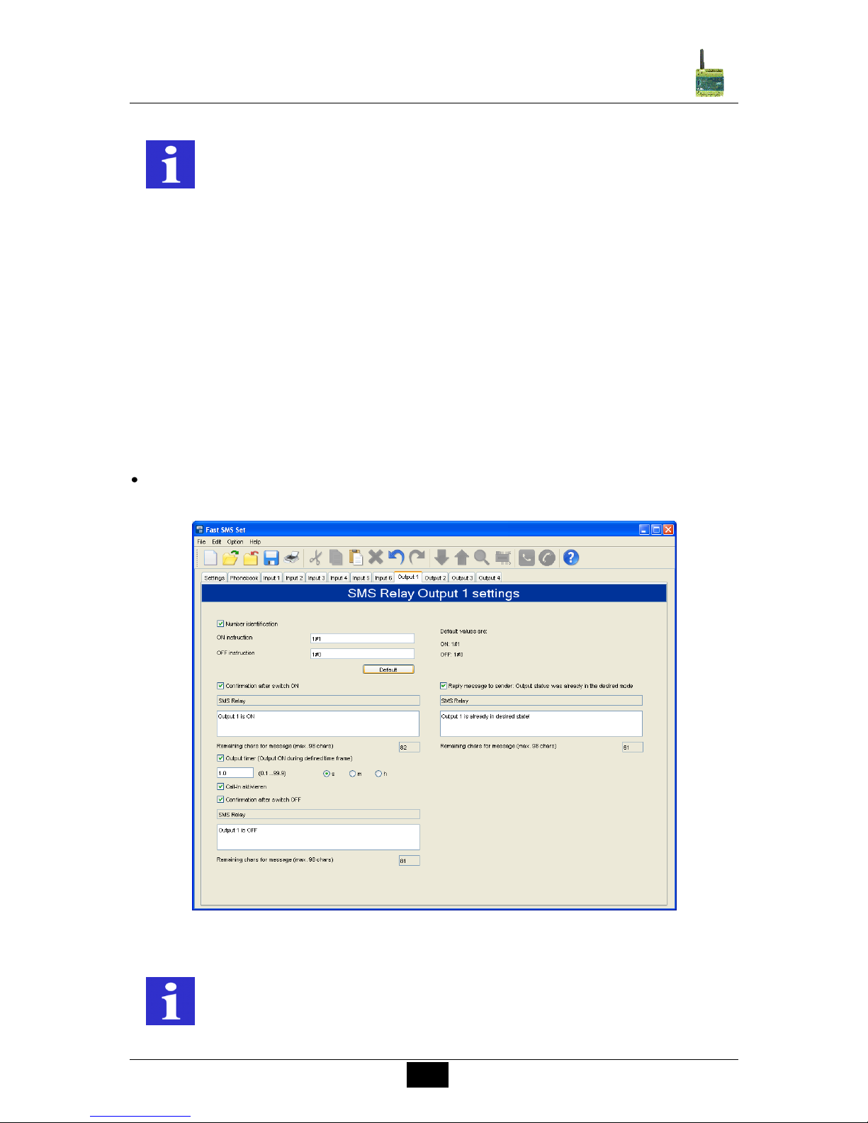
6.7.1 General
The SMS Relay has 4 relay outputs (change over contacts 10A, 250V). The outputs can be
controlled by a message i.e. they can be switched ON and OFF. Each output can be
activated individually. The message text can be edited individually. However, the device only
accepts the exact expression i.e. the message must correspond exactly with the registered
expressions. Upper and lower cases are ignored, spaces between the words and other
characters must be typed correctly. Switching commands are only accepted from numbers
which are registered in the telephone book. That means, an output can be switched ON or
OFF by receiving a SMS message. The SMS Relay confirms this with an acknowledging
message to the sender after carrying out the action. An additional message can be defined,
to inform the sender if the output is already switched to the required state and consequently
no action will be carried out.
Default
A click on this button reset the ON/OFF instructions to factory setting.
Output configuration
REMARK
It is recommended to use the delay function to avoid that several messages
are sent for the same event.
REMARK
The display of special characters in the GSM network can cause problems.
Please use only text characters and figures. The programming software
identifies special characters and an error messages will occur.
Page 28
28
Comat SMS Relay
Operating instructions SMS Relay ba_smsrelay_1010_e
6.7.2 Timer function
An output can be switched ON for a certain time with the time function option. With that
function the output can be switched ON with an SMS message for a preset time. The output
will switch OFF again automatically without the need of receiving an OFF message again
after that time has elapsed. Time delays of 0.1 seconds to 99.9 hours are possible. The
output OFF is reconfirmed to the sender after set time has expired. If a switch-OFF message
is received before the set time has elapsed, the output will ignore the remaining ON time and
switches to OFF status immediately. The default of that timing function is normally inactive
and therefore must be activated.
6.7.3 CALL-IN function
The CALL-IN function allows the user to activate the outputs by phone call for a certain time
as described in chapter 6.7.2. The device detects the incoming call and switches the outputs
without answering. The outputs are automatically switched-off after the preset time. This
allows activating a process without costs.
7. Remote Access
7.1 General
The feature „Remote Access” allows modifying the configuration of a SMS Relay by remote
access, with the configuration software FAST SMS Set (from version 3.0) and a GSM
modem (DATA call to the SMS Relay). After the remote connection is established, all the
modifications can be done in the usual environment of FAST SMS Set The first start-up
shall be executed as described in chapter “1.1 Short description SMS Relay CMS Comat
Message System” and “6. Configuration of the SMS Relay with the FAST SMS Set™
Software”. These steps are necessary to activate the remote access.
Only the SMS Relay types CMS-10AF and CMS-10ADF are able to be modified by remote
access (the older SMS Relay types CMS-10 and CMS-10AD don’t support this functionality).
WARNING This device is not suitable for monitoring sensitive installations or
time critical processes. GSM network failure or power interruptions
cannot guarantee a secure monitoring.
REMARK
Activate the output timer to activate the field “Activate Call-In”!
REMARK
The SIM-cards used for remote access (in the relay and in the GSMmodem) need to be ready for CSD protocol. CSD (Circuit Switched Data) is
a special data communication standard. The net provider has all the
required information.
Page 29
29
Comat SMS Relay
Operating instructions SMS Relay ba_smsrelay_1010_e
7.2 Configuration of Remote Access
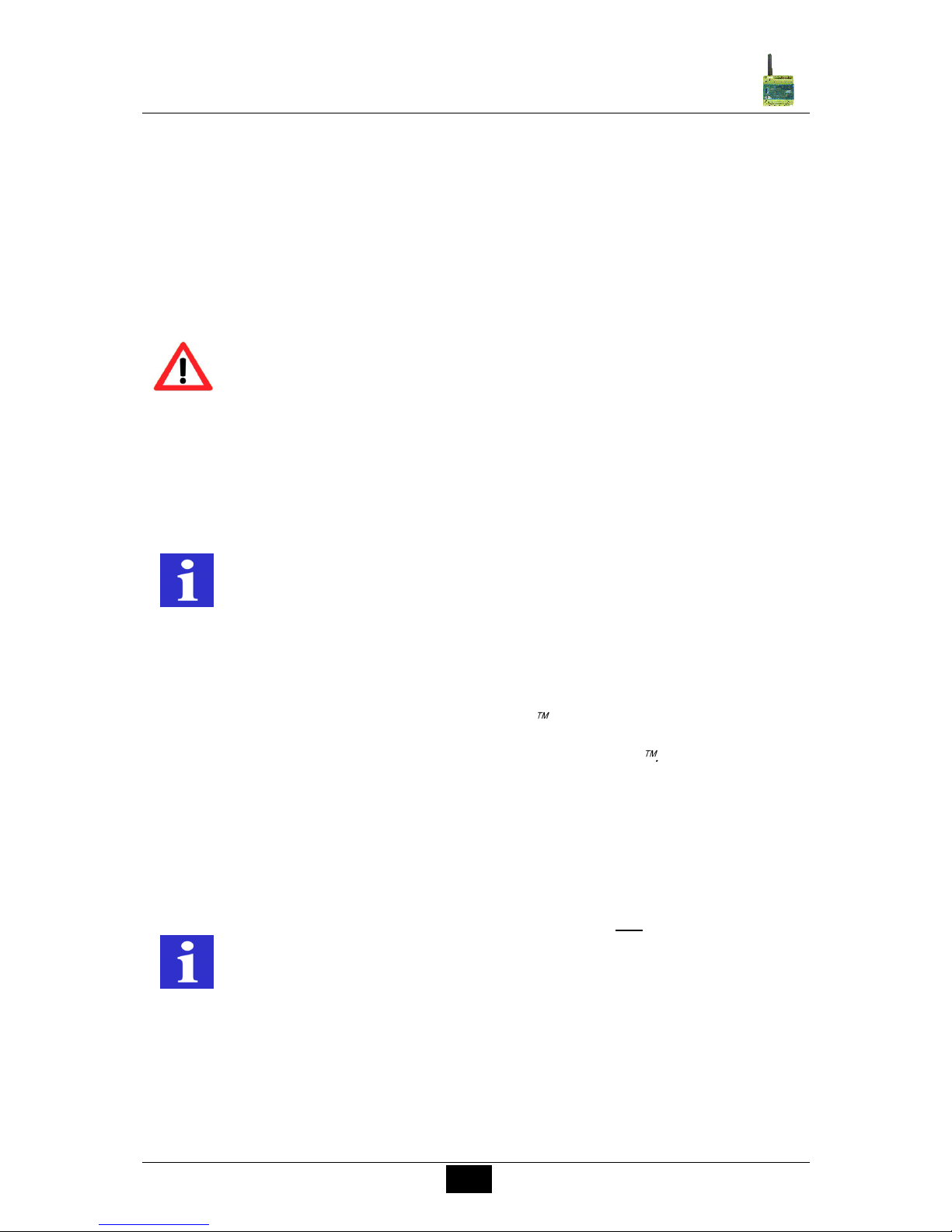
The activation of the remote access is set in the configuration software FAST SMS Set in
the general settings.
General settings
A personal password prevents unauthorized access.
Warning disable remote access
REMARK
Remote Access has to be set up by a conventional serial cable connection
(RS232) with a PC/notebook for the first time.
WARNING
The remote access can be deactivated in the remote access mode. After
deactivating, the device can not be reached and configured over the mobile
network anymore. Remote Access can only be enabled again over a
conventional serial cable connection (RS232) with a PC/notebook.
Page 30
30
Comat SMS Relay
Operating instructions SMS Relay ba_smsrelay_1010_e
7.3 Connection establishment
A SMS Relay with activated remote access and a GSM modem are necessary to establish a
connection for communication. The GSM modem is connected to a PC or a notebook (the
SMS Relay has a GSM modem already integrated).
After connecting the modem with the PC / notebook and successful connection to the
network, the PC / notebook can communicate with the SMS Relay over the GSM modem.
Afterwards, configuration data’s for the SMS Relay will be uploaded over the GSM
connection to the Relay or data’s from the Relay can be downloaded to the PC / notebook.
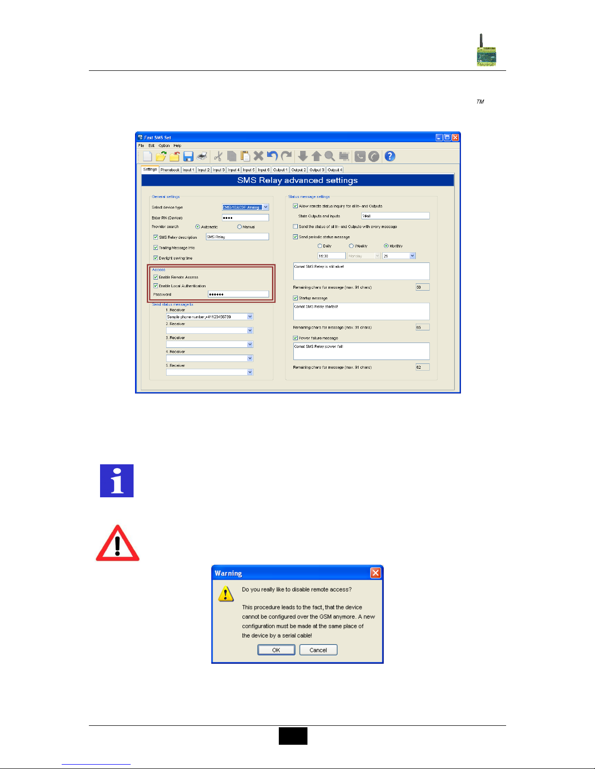
In order to establish a connection over GSM to the SMS Relay, the option Modem
connection has to be selected. The software supports some modem types and shows a
selection. Only these modems were tested by Comat AG and guarantee support by the
software. The modems are available from Comat AG.
After choosing the specific modem type, the PIN of the SIM card must be entered into the
respective window. These data are confirmed by clicking OK.
Communication settings
REMARK
For the duration of the data communication between the GSM modem and
the SMS Relay same connection fees are billed as for normal phone calls
(Please pay attention in other countries because of the roaming fees). The
connection should be disconnected after the data transfer.
REMARK
In order to reduce communication time and to avoid high phone costs, it is
advised to create the SMS Relay configuration first and to save it on the PC
/ notebook. Establish the remote connection with the SMS Relay and then
transfer the final configuration.
REMARK
Comat AG advises to use only Comat-tested modems. The functionality of
other modems cannot be guaranteed. Under certain circumstances,
unsupported modems may work as well if previously configured with the
respective AT commands. Comat AG is not able to provide any support for
modem configurations if other than recommended modems are used.
Page 31
31
Comat SMS Relay
Operating instructions SMS Relay ba_smsrelay_1010_e
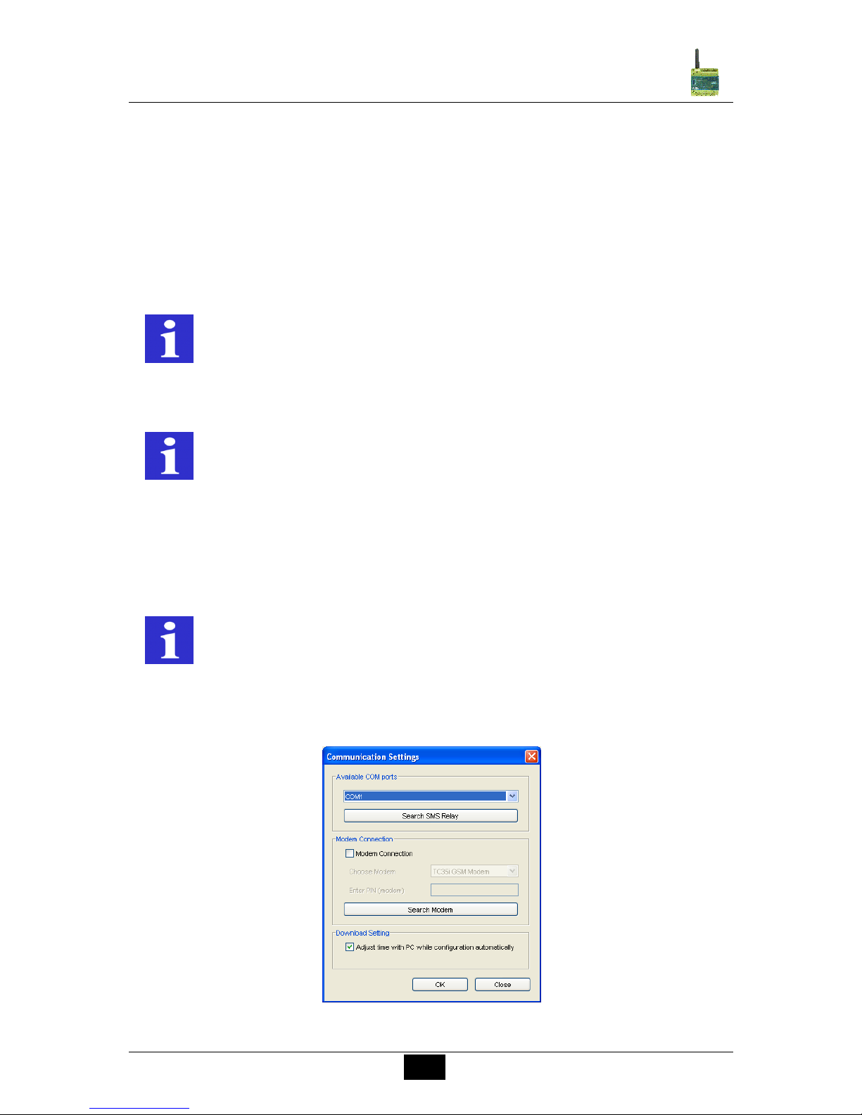
The connection to the remote SMS Relay is now built up and established. In the menu list
and in the menu Option, the remote access button is shown active.
Remote access button
If remote access is selected, FAST SMS Set starts to establish a data connection via the
modem. To set up this connection, the software is asking for the phone number of the SMS
Relay and for the password to enable the remote access.
Phone number for data call
If the data connection fails, try again to establish the connection from the beginning (Please
note that it may take up to one minute to establish the connection).
As soon the connection is build up successfully, the modification of the SMS Relay is now
possible as described in the chapters before. Please note, that the data transfer over the
GSM network takes some time and the system requires as well time to read and transfer
data from the remote SMS Relay.
REMARK
The data transfer over GSM (remote access) takes more time as the direct
access over the serial interface.
Page 32
32
Comat SMS Relay
Operating instructions SMS Relay ba_smsrelay_1010_e
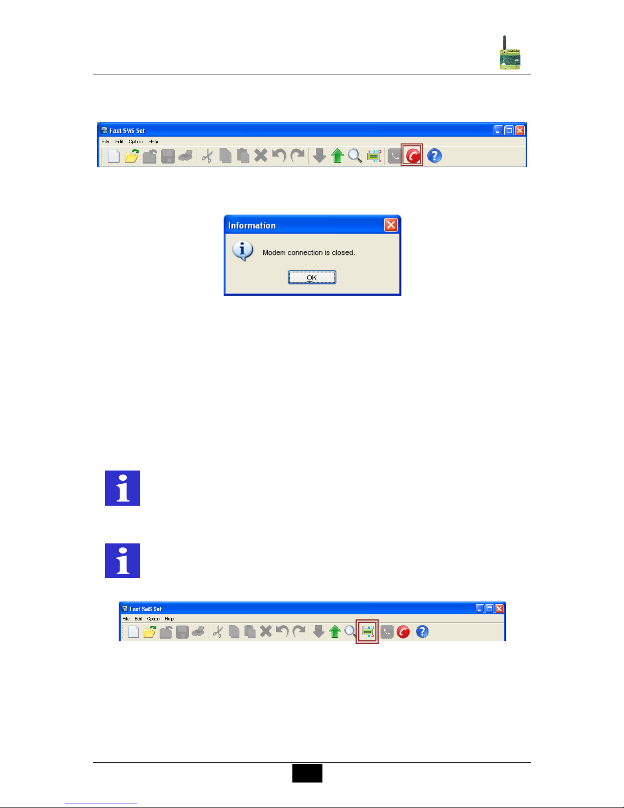
The breakup of the GSM connection takes place in reversed order. Select Close remote
connection in the menu list or in the menu Option.
Disconnect remote access
Modem connection is closed
The time out of the data connection is 15 minutes. After elapsing of this time, the connection
is disconnected. The connection has to be set up again for a new access or communication.
7.4 I/O status remote request
With a successful established data connection (via GSM-network connection or via a serial
cable connection RS232), the user can ask for the status of all inputs and outputs of the SMS
Relay including analogue input values.
Read I/O states
REMARK
Modification of values and settings over remote access will not be
immediately showed in the I/O states display window. This takes some time
and depends on the scanning cycle.
REMARK
The data transfer over GSM (remote access) takes more time as the direct
access over the serial interface.
Page 33
33
Comat SMS Relay
Operating instructions SMS Relay ba_smsrelay_1010_e
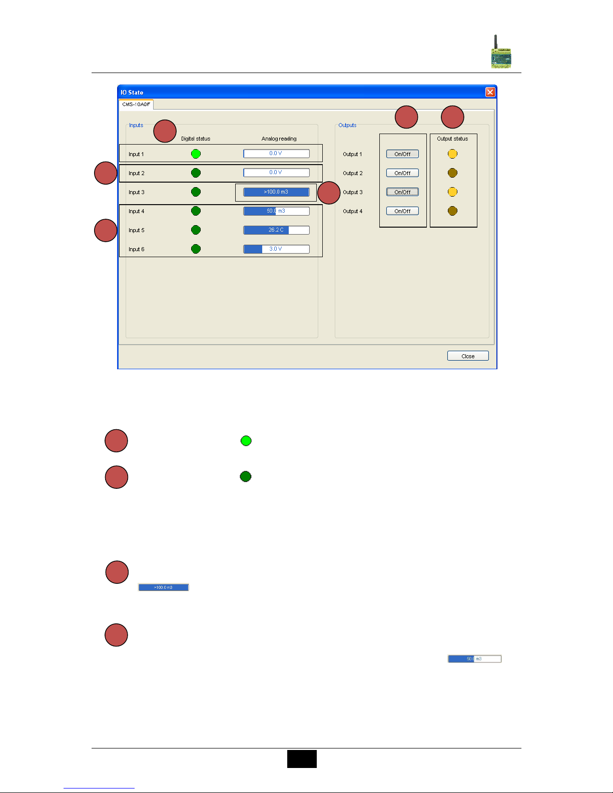
I/O States - Layout
7.4.1 Digital inputs
Digital input ON
Digitale input OFF
7.4.2 Analogue inputs
The measuring bar displays the input value with the configured unit.
The measuring range of the analogue signal is from 0V to 10V (resp. 4…20mA). If
the analogue signal is more than 10V (20mA), the measuring bar displays this with
at the specific inputs. The display shows the measuring unit and the
pre-configured maximum value.
If the signal is within the measuring range, the length of the bar represents the
value proportional to the analogue signal. That means, if the minimum value of 0V
(4mA) corresponds to 0m3 and the maximum value of 10V (20mA) corresponds to
100m3, the measuring bar will show with half of the maximal length
(corresponds to 50m3). Other values will be displayed proportional to the
measuring range.
1 2 3 4 5 6 1 2 3
4
Page 34
34
Comat SMS Relay
Operating instructions SMS Relay ba_smsrelay_1010_e
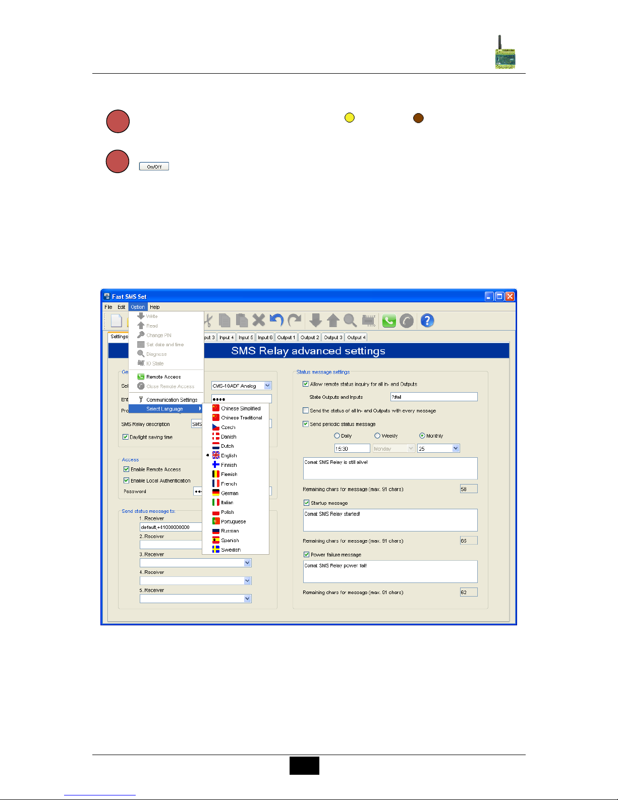
7.4.3 Outputs
The states of the outputs are displayed with ON and OFF.
All the outputs can be remotely controlled. With a simple mouse click on the
button of the specific output, the output is switched.
8. Language selection
8.1 General
Several languages of the SMS Relay configuration software “Fast SMS Set”™ are available.
The languages can be selected from a library. It is not necessary to restart the program after
selecting another language. Select the language menu to access the available configuration
languages and click onto the required language from the library.
Select language
6
5
Page 35
35
Comat SMS Relay
Operating instructions SMS Relay ba_smsrelay_1010_e
9. Technical items
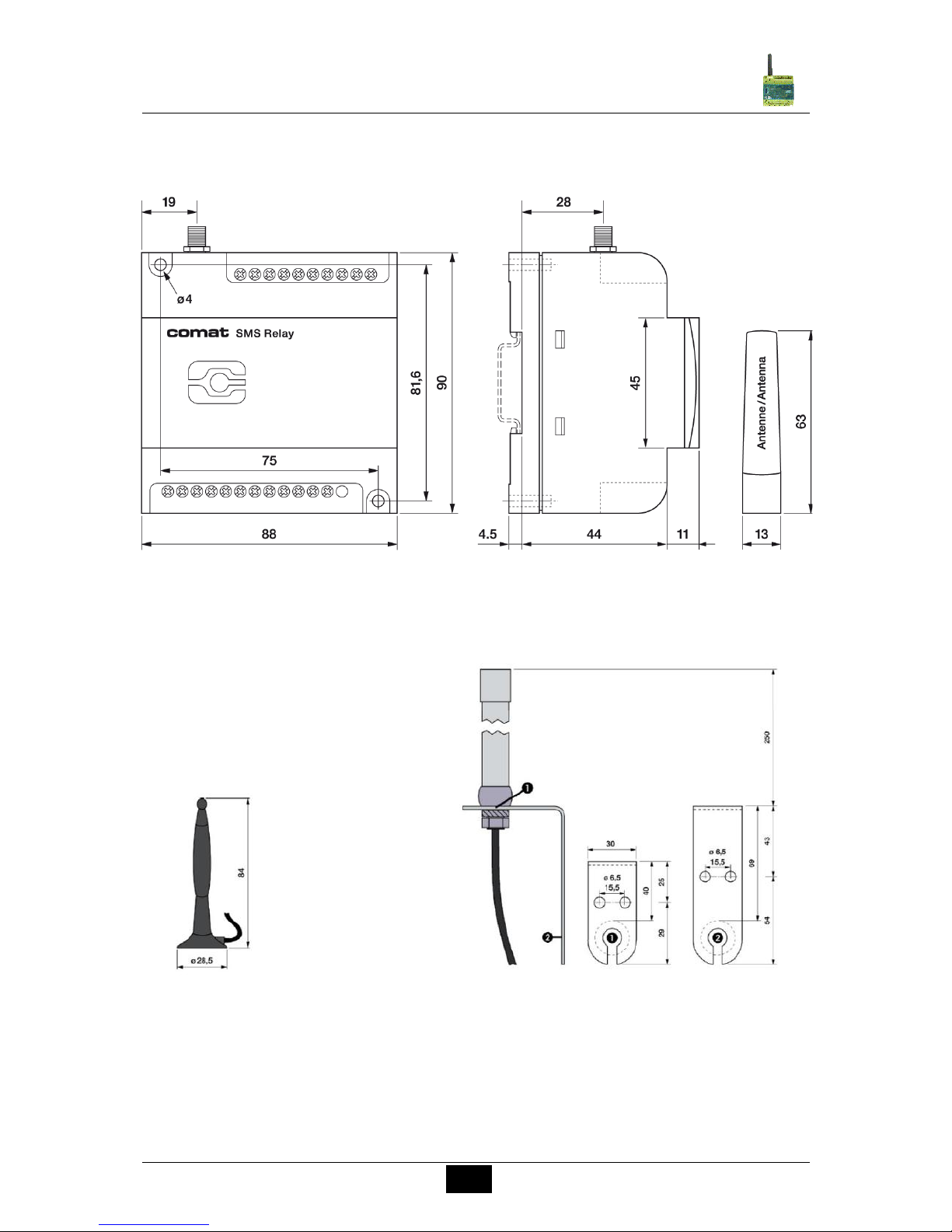
9.1 Dimension
SMS Relay - Dimension
Antennas - Dimension
Page 36
36
Comat SMS Relay
Operating instructions SMS Relay ba_smsrelay_1010_e
9.2 Technical data
9.2.1 CMS-10F
Operating voltage
AC 110-240V~ 50/60Hz
DC 12-48V max. 10%
Power consumption
8VA / 6W
6W
Switching capacity
4 x 10 A 250 V CAUTION: total current of all outputs:20 A
Temperature range
Temp: -25…+55°C
Rel. humidity: 5…95% (non condensing)
Protection: IP 20
Inputs
6x digital trigger level 85V~
6x digital trigger level 9.5V
Outputs
4x CO contacts
Provider (Phone / Network)
User selectable (depending on SIM card)
9.2.2 CMS-10ADF
Operating voltage
DC 12-48V max. 10%
Power consumption
6W
Switching capacity
4 x 10 A 250 V CAUTION: total current of all outputs: 20 A
Temperature range
Tu : -25…+55°C
Rel. humidity: 5…95% (non condensing)
Protection: IP 20 built in
Inputs
6 Inputs, for each Input elective digital or analog
Digital: trigger level 9.5V
Analogue: 0…10V analogue signal, 10 Bit A/D-converter
Outputs
4x CO contacts
Provider (Phone / Network)
User selectable (depending on SIM card)
9.2.3 CMS-10ACDF
Operating voltage
DC 12-48V max. 10%
Power consumption
6W
Switching capacity
4 x 10 A 250 V CAUTION: total current of all outputs: 20 A
Temperature range
Tu : -25…+55°C
Rel. humidity: 5…95% (non condensing)
Protection: IP 20 built in
Inputs
4 voltage inputs (I1-I4), for each Input elective digital or analog
Digital: trigger level 9.5V
Analogue: 0…10V analogue signal, 10 Bit A/D-converter (LSB: 12.5 mV)
2 current inputs (I5 and I6), for each only analog
Analogue: 4…20mA analogue signal, 10 Bit A/D-converter (LSB: 20 µA)
Outputs
4x CO contacts
Provider (Phone / Network)
User selectable (depending on SIM card)
Page 37
37
Comat SMS Relay
Operating instructions SMS Relay ba_smsrelay_1010_e
10. Ordering information
Type
Description
CMS-10F/AC110-240V
SMS Relay AC 110-240V with 6 digital inputs incl. small antenna (CMS-ANT)
CMS-10F/DC12-48V
SMS Relay DC 12-48V with 6 digital inputs incl. small antenna (CMS-ANT)
CMS-10ADF/DC12-48V
SMS Relay DC 12-48V with 6 digital and/or analogue inputs incl. small antenna (CMS-ANT)
CMS-10ACDF/DC12-48V
SMS Relay DC 12-48V with 2 analog current inputs and 4 analog and/or digital voltage inputs
incl. small antenna (CMS-ANT)
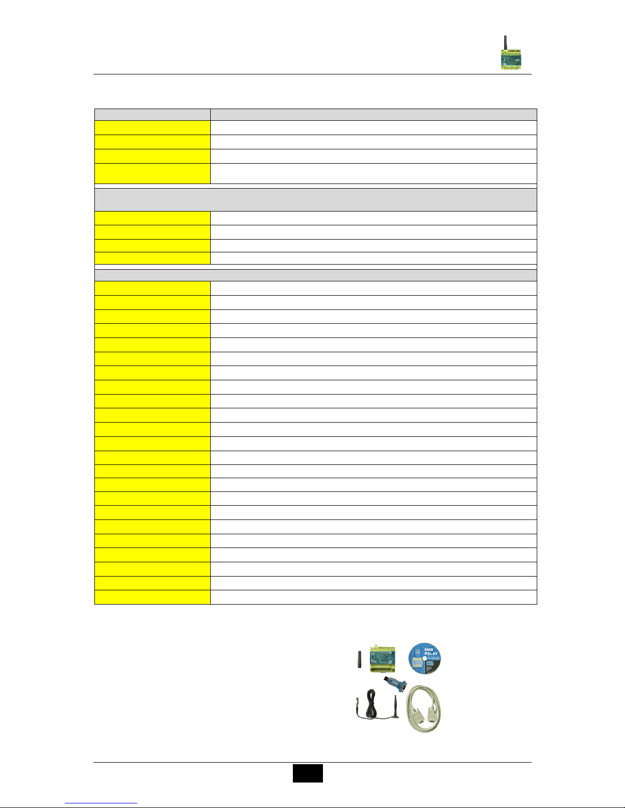
KIT consisting of: A base unit with small antenna, antenna with magnetic pod and 2.5 m cable, programming cable, USB-RS232 interface
convertor, CD with FAST SMS SETTM programming software and operation manual.
CMS-10FKIT/AC110-240V
Complete installation kit for SMS Relay AC 110-240V with 6 digital inputs
CMS-10FKIT/DC12-48V
Complete installation kit for SMS Relay DC 12-48V with 6 digital inputs
CMS-10ADFKIT/DC12-48V
Complete installation kit for SMS Relay DC 12-48V with 6 digital and/or analogue inputs
CMS-10ACDFKIT/DC12-48V
Complete installation kit for SMS Relay DC 12-48V with 2 analog current inputs and 4 analog voltage inputs
Accessories
CMS-RS232
SMS Relay programming cable RS232
CMS-USB
USB→RS232 interface converter (incl. driver CD)
CMS-ANT
Small spare antenna for base unit, length of 63 mm
CMS-ANT-MAG/2.5M
Antenna with magnetic pod and 2.5 m antenna cable
CMS-ANT-SPEZ/5M
External antenna with 5m antenna cable
CMS-ANT-KAB/5M
Antenna cable 5 m (extension)
CMS-ANT-KAB/10M
Antenna cable 10 m (extension)
CMS-ANT-KAB/20M
Antenna cable 20 m (extension)
CMS-ANT-ADAPT
Adaptor FME to SMA plug
CMS-CAP
Device cover (spare)
CMS-CD
CD with FAST SMS SETTM programming software and operation manual
DR-15-24
Power supply 15W, 24V. DIN rail mounting
DR-30-24
Power supply 30W, 24V. DIN rail mounting
4114
Universal transmitter PReasy
4501
Display front (to PReasy 4114)
ZPt-10-H
Pt100 Amplifier
RF01-U
Room temperature sensor 0 … 50 °C without display
RF01-U-D
Room temperature sensor 0 … 50 °C with display
RTBSB-001-010
Room thermostat 5…30 °C with operation controls
WF50 ext-U
Outdoor temperature sensor -50 … +50 °C
KS-110
AC sensor for monitoring of humidity and temperature in control panels, archives and cabinets
PS1
Water gauge suitable for application of level measurements in water installations
CMS-GSM-MOD
GSM module (Connected to USB port of the PC) for remote access to the SMS Relay
SMS Relay KIT:
CMS-10FKIT/…
CMS-10ADFKIT/…
CMS-10ACDFKIT/…
Page 38

38
Comat SMS Relay
Operating instructions SMS Relay ba_smsrelay_1010_e
11. Notes
Page 39

39
Comat SMS Relay
Operating instructions SMS Relay ba_smsrelay_1010_e
Page 40
40
Comat SMS Relay
Operating instructions SMS Relay ba_smsrelay_1010_e
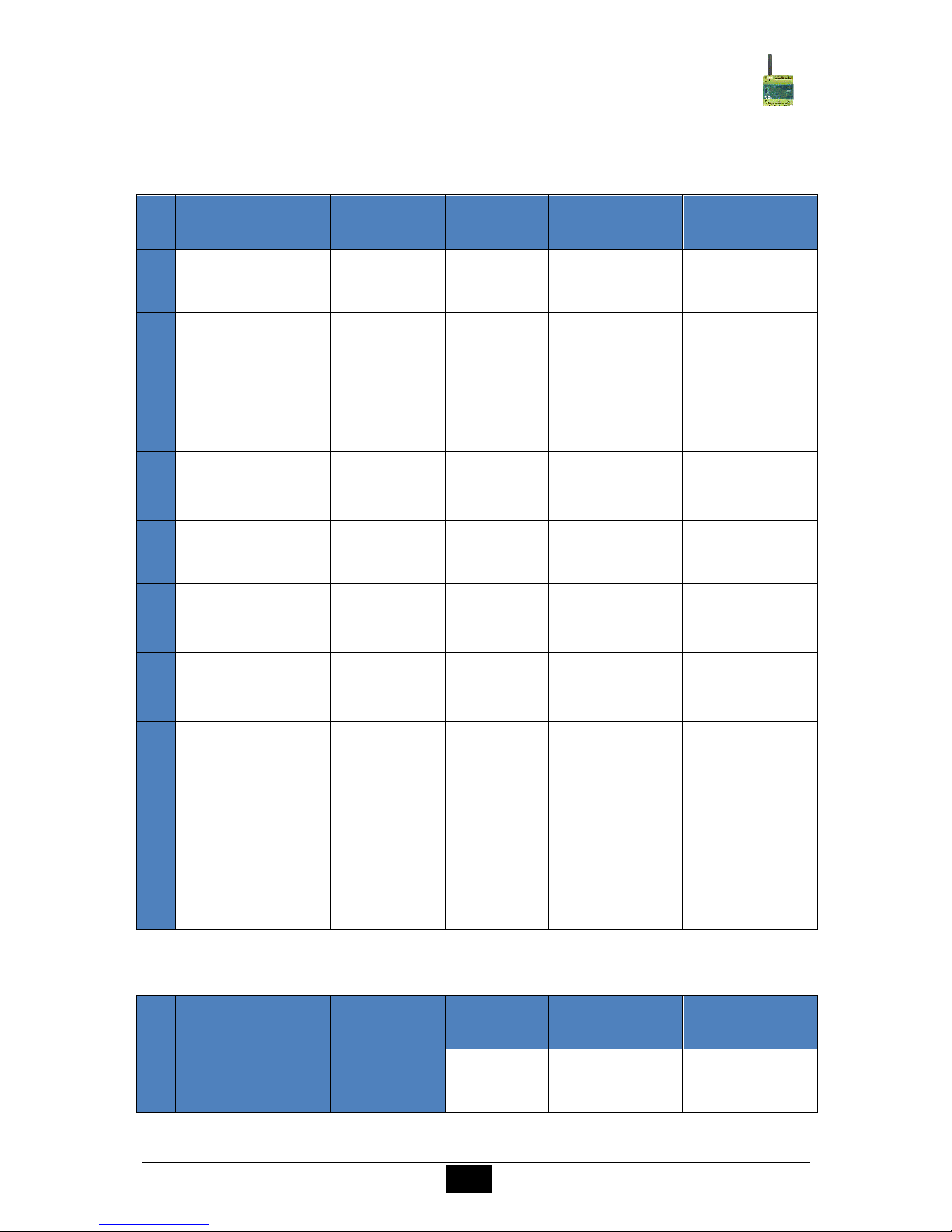
12. Overview of your devices and phone numbers
Devices
N°
SMS Relay
description
Device type
A/D
PIN
Password
Phone number
1
2
3
4
5
6
7
8
9
10
Modem
N°
SMS Relay
description
Device type
A/D
PIN
Password
Phone number
1
 Loading...