

Page 1
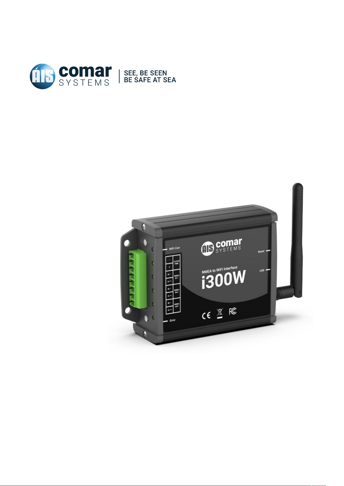
USER MANUAL i300W
NMEA TO WIFI INTERFACE
SKU 000-0000
i300W-MA-v00r00
2019-05-09
ENGLISH
Page 2

Page 3

i300W
CONTENTS
1 i300W NMEA TO WIFI INTERFACE ............................................................ 5
2 DOCUMENT ............................................................................................... 6
2.1 About This Manual .............................................................................................. 6
3 NOTICE ...................................................................................................... 7
3.1 Copyright ............................................................................................................ 7
4 GENERAL NOTICES ................................................................................... 8
5 INTRODUCTION ......................................................................................... 9
5.1 Parts List ............................................................................................................. 9
6 MAJOR DIMENSIONS .............................................................................. 10
7 INSTALLATION ......................................................................................... 11
7.1 Before you Start ................................................................................................ 11
7.2 Installing the Unit .............................................................................................. 11
7.3 Installation Step 1 ............................................................................................. 11
7.4 Installation Step 2 ............................................................................................. 11
7.5 Installation Step 3 ............................................................................................. 12
7.5.1 Connection Diagram ............................................................................ 13
8 OPERATION ............................................................................................. 14
8.1 LED Indicator description ................................................................................. 11
8.2 Default settings ................................................................................................. 11
8.3.1 Installing the i300W Setup Tool ........................................................................ 11
8.3.2 Connecting to your i300W / Read Data ............................................................ 11
8.3.3 Changing the configuration / Write Data .......................................................... 11
8.4 Factory Reset .................................................................................................... 11
9 FAULT FINDING ....................................................................................... 17
9.1 No green ON LED is displayed ........................................................................ 17
9.2 No DATA LED flashing ...................................................................................... 17
9.3 Unable to see the i300W Network .................................................................... 17
9.4 Unable to connect to the unit ........................................................................... 17
10 SPECIFICATION ....................................................................................... 18
10.1 Physical ............................................................................................................. 18
10.2 Electrical ............................................................................................................ 18
10.3 Operational ....................................................................................................... 18
10.4 Environmental ................................................................................................... 18
10.5 Additional Information ....................................................................................... 18
3
Page 4

i300W
11 SAFETY AND SECURITY ......................................................................... 19
12 LIMITED WARRANTY ............................................................................... 19
4
Page 5
i300W
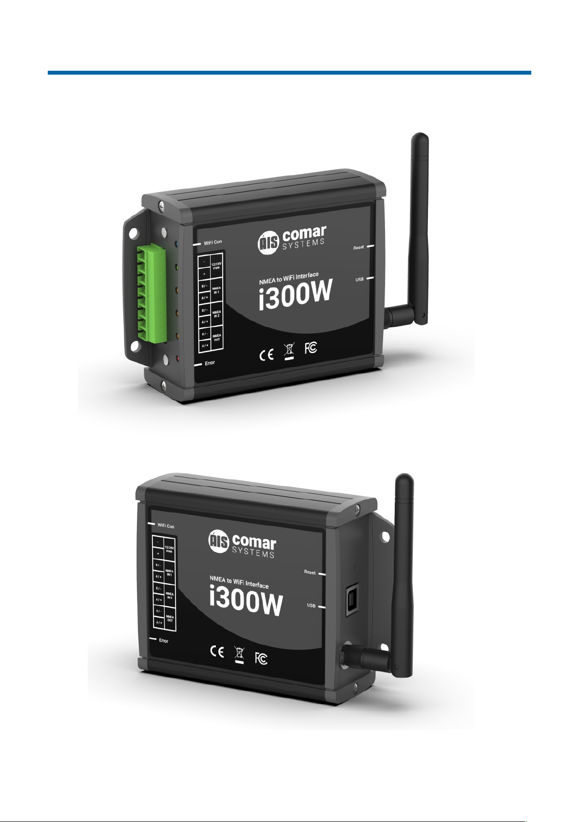
i300W NMEA TO WIFI INTERFACE
5
Page 6
i300W
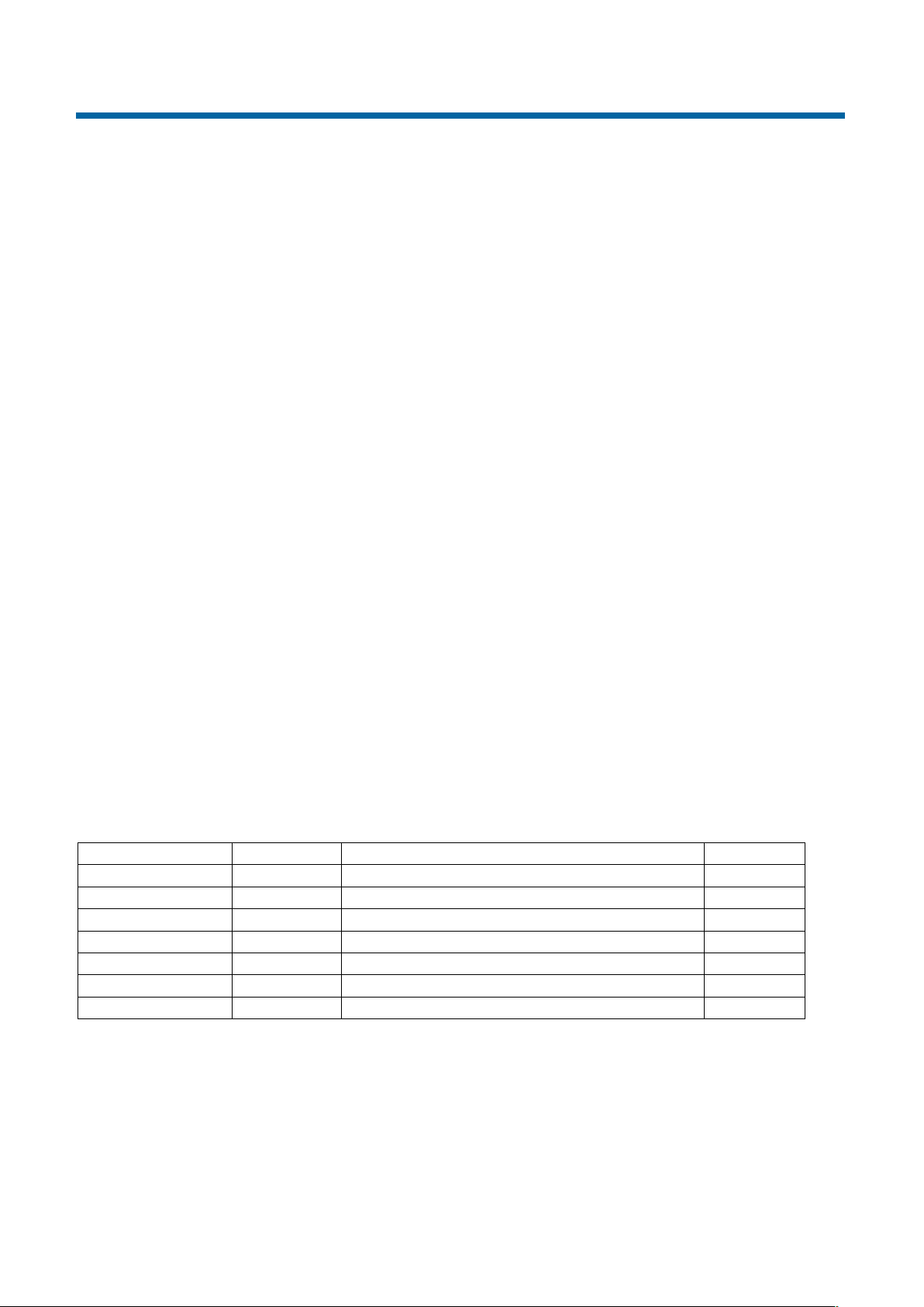
Document name:
Date:
Details:
Author:
i300W-MA-v00r00
2019-05-09
First issue
JV
1 DOCUMENT
1.1 About This Manual
This Manual provides installation, operating Instructions and fault-finding procedures for the
equipment to which it relates.
After installation, this manual should remain with the vessel to which it relates.
This manual may also be made available in electronic Portable Document Format (PDF). In PDF
format, the following categories are all enabled as active hyperlink references: (1) The titles of each
section; (2) document cross-references; (3) the table of contents.
This document may therefore be navigated quickly and effectively by using a mouse or other pointing
device to activate each of these hyperlinks. This is a printer friendly document, designed to be
printed 2-sided as a booklet with A5 pages on A4 stock paper.
6
Page 7

i300W
COMAR SYSTEMS
Vittlefields Technology Centre
Forest Road
NEWPORT
Isle of Wight
PO30 4LY
UNITED KINGDOM
tel: +44 (0)1983 828900
email: [email protected]
web: www.comarsystems.com
COMAR SYSTEMS reserves the right to make changes to its products and specifications without notice
2 NOTICE
2.1 Copyright
The copyright and all rights of a like nature in respect of this publication in any part of the world are
the property of COMAR SYSTEMS LTD. (COMAR).
No part of this document may be reproduced or transmitted in any form or by any means, whether
electronic, mechanical, photocopying, recording or otherwise, nor stored in any information retrieval
system of any kind, nor used for tendering or manufacturing, nor communicated to any other person
without the written permission of COMAR.
The recipient of this document, as its registered holder, must exercise due diligence in ensuring that
the above conditions are observed (Errors and Omissions Excepted).
Any enquires relating to this document or its contents should be addressed, in writing, in the first
instance to COMAR SYSTEMS LTD.
7
Page 8

i300W
~
i
i
i
3 GENERAL NOTICES
SAFETY: Make sure the power supply is switched off before you make any electrical
connections to the unit.
INSTALLATION: This equipment must be installed in accordance with the instructions
provided in this manual. Failure to do so could result in poor performance, personal injury
and/or damage to your vessel and/or connected equipment.
CABLES: The supplied cables should only be cut, shortened or lengthened by an
appropriate supplier.
COMPASS: The compass safe distance of this unit is 0.5 m or greater for 0.3° deviation.
In accordance with a policy of continual development and product improvement, hardware and
software may be upgraded from time to time, and future versions of equipment may therefore not
correspond exactly with this manual.
When necessary, upgrades to the product will be accompanied by updates or addenda to this
manual. Information contained in this manual is liable to change without notice.
Comar Systems Ltd. disclaims any liability for consequences arising from omissions or inaccuracies
in this manual and any other documentation provided with this product.
8
Page 9
i300W
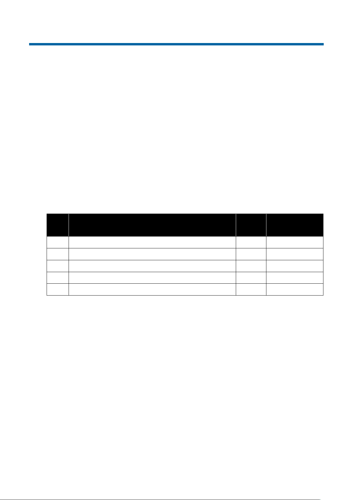
Item:
Description:
No.
included:
COMAR
SKU Number:
1
i300W NMEA To WIFI Interface
1
000-0000
2
WiFi - Antenna
1
000-0000
3 1
000-0000
4 1
000-0000
5
i300W Manual
1
000-0000
4 INTRODUCTION
Congratulations on the purchase of your Comar i300W NMEA To WiFi Interface.
The i300W NMEA to WiFi Interface provides a low cost method of setting up a wireless network onboard. This will enable you to use marine navigation programs or apps on your smartphone, tablet
or PC to display all your electronic data including position, AIS data, depth, wind, compass heading
and more.
This manual describes the installation and operation of the i300W.
● Before operating the unit you should familiarise yourself with this user manual.
4.1 Parts List
On delivery, carefully inspect the contents of the packing case. Note any damage or any missing
items. Ensure that the correct parts are included for your application.
Table 5-1:
9
Page 10
i300W
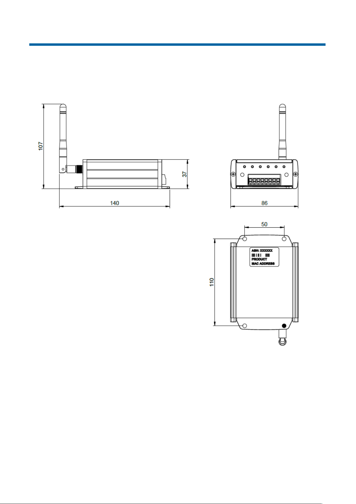
5 MAJOR DIMENSIONS
All dimensions mm:
10
Page 11

i300W
6 INSTALLATION
6.1 Before you Start
You will need the following items and tools to complete the installation:
● i300W NMEA To WiFi Interface
● Access to 12 V dc or 24 V dc power supply where the unit is to be installed, via a 1 A rated fuse
or circuit breaker / or alternatively a USB cable connected to a USB power source.
● Four screws or other fixings appropriate to the mounting location
6.2 Installing the Unit
The i300W unit is not waterproof and should be installed in a dry location. The unit can be secured
by the 4 mounting holes in the end flanges. It should ideally be installed in a location suitable for
connection to power and NMEA cables, observing a compass safe distance of 0.5 m. When
installing the unit you should consider:
● The best location for WiFi transmission, ideally within sight of the device you wish to connect to
(Mount the device away from obstructions, that can have a negative impact on wireless
performance. Also avoid mounting the unit behind any metal structures.)
● Nearby interference that can impact your i300W Interface installation
● Routing of the power cables to the unit
● Provision of sufficient space behind the unit for cable connections
● Maintaining the compass safe distance of 0.5m
● Visibility of the front panel indicators
6.3 Installation Step 1
● Secure the i300W to a flat surface in the selected location. Use four 5mm wood screws, or other
fixings suited to the material the unit is being fixed to
● The unit may be installed in any orientation
6.4 Installation Step 2
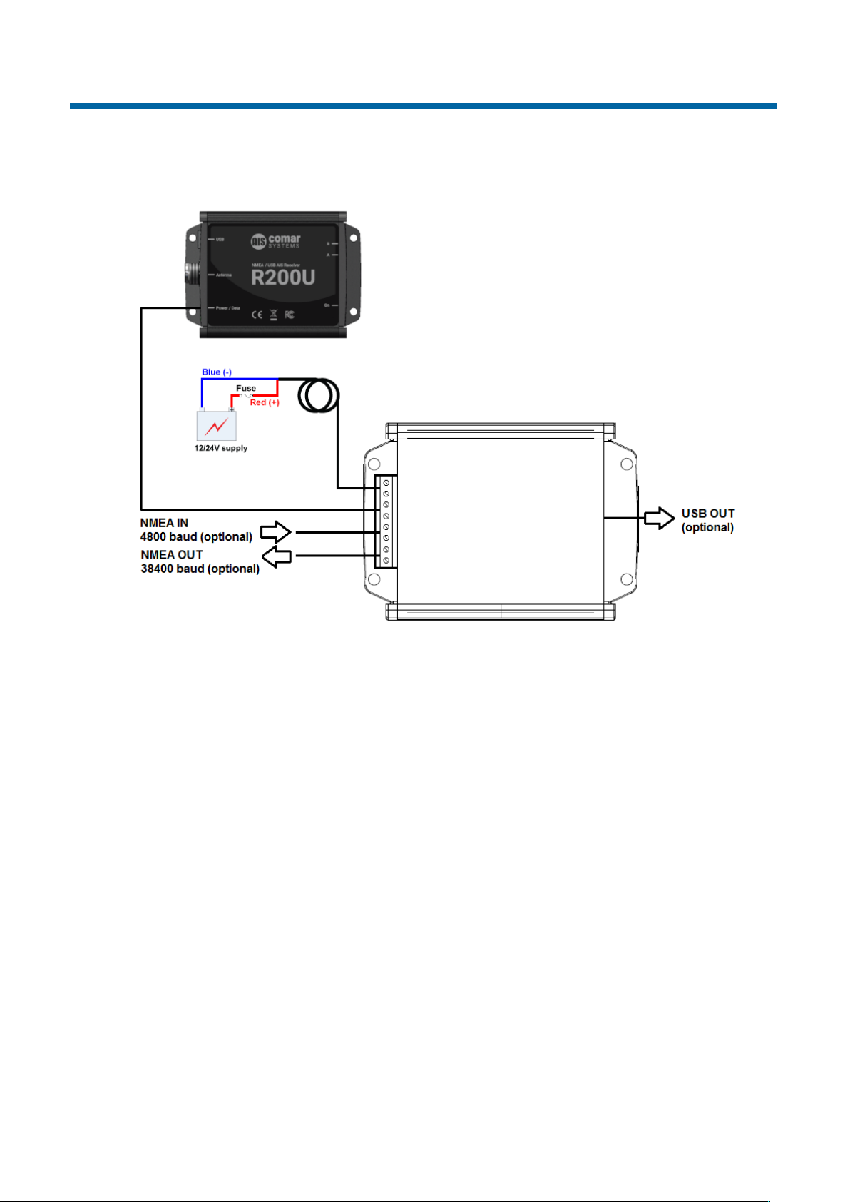
Refer to section 6.5.1 Connection Diagram. Make the electrical connections to the i300W:
● Connect 12 V dc or 24 V dc power supply cables to the power terminals. The positive power
supply wire should be connected to the positive terminal via a 1A rated fuse or circuit breaker.
The negative power supply connection should be connected to the negative terminal. /
Alternatively you can power the device through the USB socket connected to a USB power
source.
● The NMEA-2-WIFI has two NMEA 0183 Inputs, one at 38,400 baud (NMEA IN 1), and one at 4800
(NMEA IN 2) baud.
11
Page 12

i300W
The 38,400 baud NMEA data input (NMEA IN 1) would normally be connected to an external AIS
Receiver or Transponder, however it will also accept any other NMEA data at 38,400.
Any 4800 baud NMEA data such as from a GPS, Chart Plotter or Instruments can be connected
to the NMEA IN 2 terminals, observing the correct polarity. The unit can only be connected to one
piece of equipment so choose the unit that has the most information that you require. If you have
several pieces of equipment that you wish to receive data from then you may need to purchase
a NMEA Multiplexer to combine all this data into one before connecting to the WiFi unit.
If the equipment that you are connecting to has a pair of NMEA cables, normally marked NMEA
Output Positive (A) and Negative (B) these should go to the respective NMEA input on the WiFi
unit.
If the equipment has only one Positive NMEA output wire this should go to the A NMEA Input and
a wire from the B NMEA Input should then be taken to the common ground/negative of the other
equipment.
Connect a NMEA 0183 AIS source to the “NMEA IN 1” input..
6.5 Installation Step 3
Apply power and verify that the unit is operating:
● Apply power to the i300W and all connected devices.
● Verify that the green power LED on the i300W is illuminated
● Use a WiFi enabled device like a smartphone, tablet or PC and search for WiFi networks. Your
device should find the i300W network and you should be able to connect without a password.
● Wait for the connected AIS receiver to receive the first AIS messages (usually indicated by flashing
LEDs). Once the AIS receiver is sending NMEA 0183 AIS data to the i300W you should see the
indicator LED “NMEA IN 1” flashing yellow.
● Now, open a marine navigation program / app that is able to process AIS messages on your WiFi
enabled device that you have connected to the i300W WiFi network. In the settings page of the
program / app set the AIS settings as follows:
Protocol: TCP
IP Address: 10.10.100.110
Port: 10110
Once sucessfully connected you should see the AIS data displayed on your screen.
12
Page 13
i300W
6.5.1 Connection Diagram
13
Page 14
i300W
LED:
Description:
WIFI CON
Indicates if a device is connected to the i300W through WiFi
PWR
On when powered
NMEA
IN 1
Flashing once with every NMEA message received at NMEA input 1
NMEA
IN 2
Flashing once with every NMEA message received at NMEA input 2
NMEA
OUT
Flashing once with every NMEA message sent through NMEA output
ERROR
Indicates that an Error occurred
Setting:
Default Value:
SSID
i300W
WIFI Key
None (open)
IP Address
10.10.100.110
Net Mask
255.255.255.0
Port
10110
Protocol
TCP
7 OPERATION
Operation of the i300W is automatic and requires no user intervention.
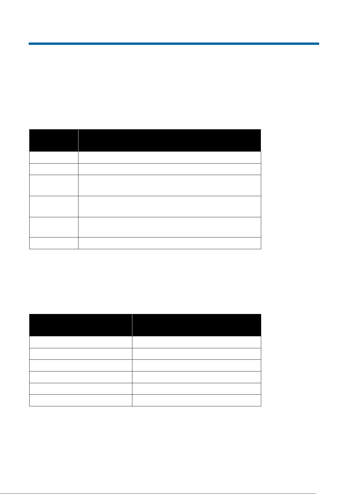
7.1 LED Indicator description
Table 8-1: LED Indicator Description
7.2 Default settings
The i300W NMEA To WIFI Interface comes preset with the following settings:
Table 8-2:
14
Page 15

i300W
7.3 Setup Tool
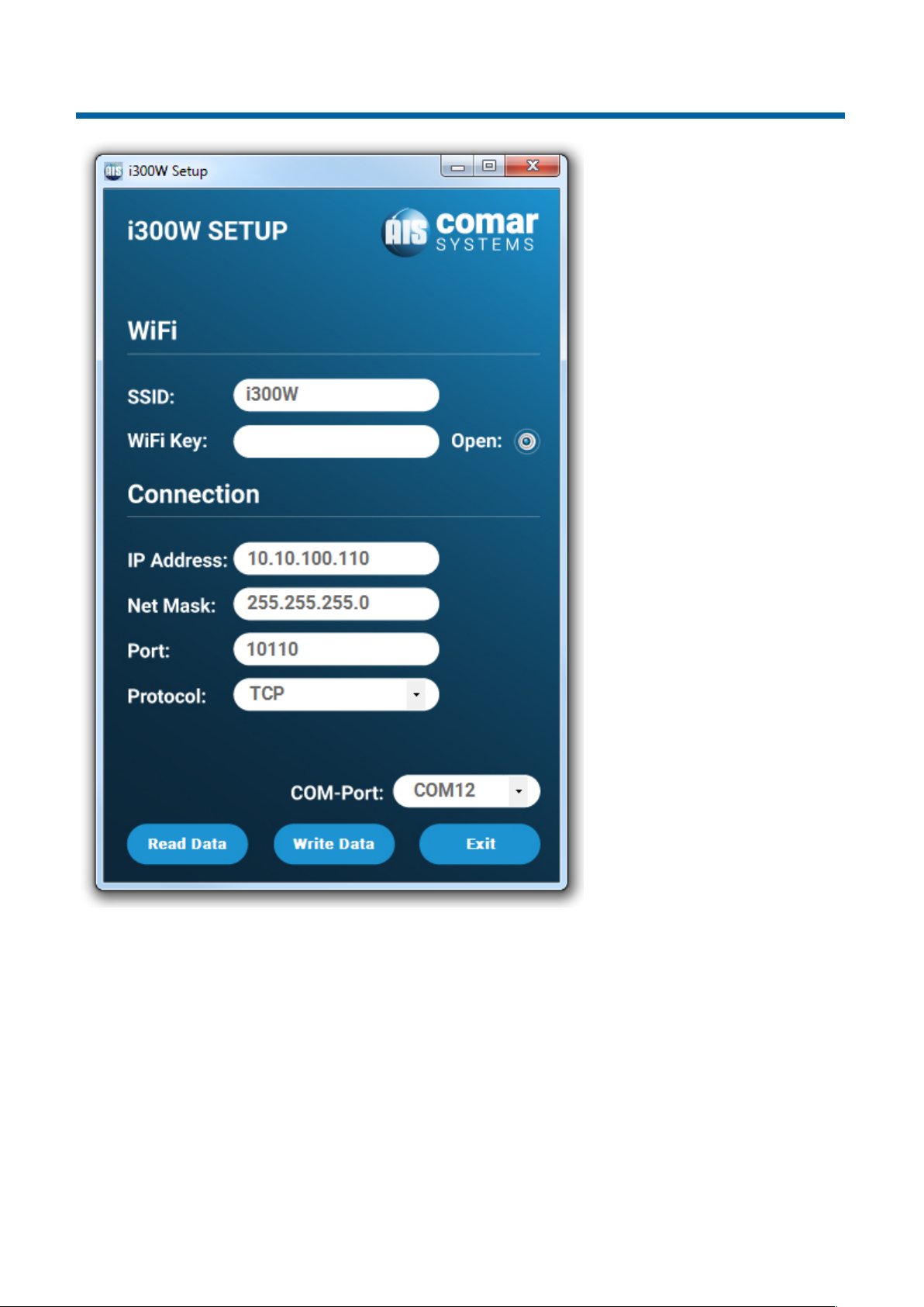
The i300W Setup Tool (supplied) allows you to configure your i300W. The Tool is compatible with
Microsoft® Windows®.
The system requirements are as follows:
● Microsoft® Windows® XP, Windows Vista, Windows 7, Windows 10 (32 and 64 bit)
7.3.1 Installing the i300W Setup Tool
The application is installed from the CD provided with your i300W interface. Insert the CD into your
computer and navigate to the i300W Setup Tool folder. Double click the setup.exe item to start the
installation and follow the on-screen instructions.
7.3.2 Connecting to your i300W / Read Data
● Before launching the i300W Setup Tool, first connect your i300W to your computer using the USB
cable. After it is connected, you can launch the i300W Setup Tool.
● Select the serial port corresponding to your i300W from the drop down menu at the bottom right
of the i300W Setup Tool window, and click the "Read Data" button.
● The i300W Setup Tool is now communicating with your i300W and will display the current setup of
your device.
7.3.3 Changing the configuration / Write Data
● Make changes to the configuration data as desired.
● Click the "Write Data" button to set up your device with the new configuration.
● A message box confirms the successful configuration of your device. Press “Exit” and disconnect
your device. The new configuration becomes active instantly.
15
Page 16
i300W
7.4 Factory Reset
To reset the i300W to default factory settings, disconnect all power sources from the unit (power
cables as well as USB cable). Using a paper clip, push the reset button (a click will be felt), power
on the device either through the power connection or the USB cable and hold down the reset
button for at least 5 seconds, after which the factory defaults will be restored.
16
Page 17

i300W
8 FAULT FINDING
8.1 No green ON LED is displayed
● Check power supply connections and fuse or circuit breaker
● Check polarity of power supply connections
● Check power supply voltage
8.2 No DATA LED flashing
● Check that the NMEA equipment is switched on
● Check polarity of the NMEA cables: A – A (or +), B – B (or -)
8.3 Unable to see the i300W Network
● Move closer to the unit to improve radio reception
8.4 Unable to connect to the unit
● Retry connecting, initially the device may take a while to negotiate with the network, as a radio
device, it is possible to suffer from interference in a busy marina, moving closer to the device will
improve the signal and give a more reliable connection.
17
Page 18
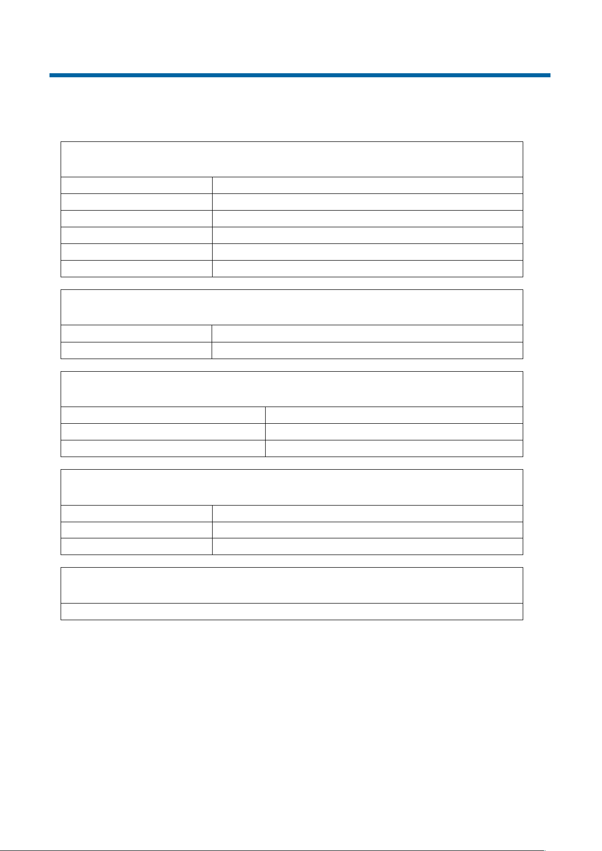
i300W
9.1 Physical
Weight:
200 g
Dimensions:
L 120 x W 86 x D 37 mm
Mounting:
To flat surface
Connections:
8-way Screw Terminals
Construction:
Aluminium housing
Finish:
Grey aluminium housing; grey plastic front panel
9.2 Electrical
Input Voltage:
9-30 V DC
Current:
100mA @ 12V DC
9.3 Operational
Input:
NMEA 0183 at 4800 Baud and 38,400 Baud
Output:
NMEA 0183 at 38,400 Baud
WIFI:
2.4GHz 802.11b/g/n
9.4 Environmental
IP rating:
IP40
Operating Temperature:
-15°C to +55°C
Compass:
Safe distance 50 cm
9.5 Additional Information
A suitable App or Program is required to display the data
9 SPECIFICATION
18
Page 19

i300W
10 SAFETY AND SECURITY
Please observe the following procedures to ensure safety of personnel installing and operating the
equipment:
1. Ensure all power to the unit is disconnected and locked-out during installation,
maintenance and removal procedures
2. Ensure power is disconnected and locked-out in the event of mechanical damage to the
unit, rendering internal parts accessible to personnel
3. Only the electrical power of the specified voltage should be connected to the unit
4. The panel to which the unit is mounted should be designed to provide adequate
mechanical support. This minimises the possibility of damage or injury caused under
mechanical shock conditions
5. Care should be taken to ensure the fixings used to mount the unit to the panel are
correctly fitted and retain their mechanical integrity over time
11 LIMITED WARRANTY
COMAR SYSTEMS LTD. warrants this product to be free from defects in materials and manufacture
for one year from the date of purchase. Comar Systems Ltd will, at its sole option, repair or replace
any components that fail in normal use. Such repairs or replacement will be made at no charge to
the customer for parts and labour. The customer is, however, responsible for any transportation
costs incurred in returning the unit to Comar Systems Ltd.
This warranty does not cover failures due to abuse, misuse, accident or unauthorised alteration or
repairs.
The above does not effect the statutory rights of the consumer.
Note: Every effort has been made to ensure that all information contained in this manual is accurate
at the time of going to press. We therefore cannot take any responsibility for the content of this manual
and advise that you take normal steps to ensure that the information is at its most current when you
are reading this manual.
19
Page 20

i300W
NOTES
20
Page 21

i300W
NOTES
21
Page 22

i300W
NOTES
22
Page 23

i300W
NOTES
23
Page 24

COMAR SYSTEMS
Vittlefields Technology Centre
Forest Road
NEWPORT
Isle of Wight
PO30 4LY
UNITED KINGDOM
tel: +44 (0)1983 828900
 Loading...