

Page 1
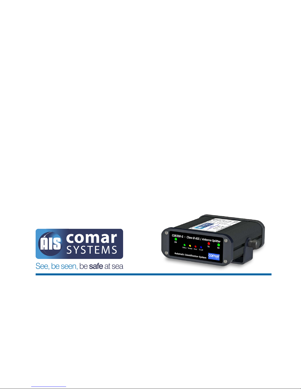
USER MANUAL CSB200-
S
CLASS ‘B’ AIS TRANSPONDER WITH ANTENNA S
PLITTER
SKU 001-
1019
CSB200
-S-MA-v02r02
SKU
003-1019
2017
-08-22
ENGLISH
Page 2

Page 3

CSB200-S
3
CONTENTS
1 CSB200-S CLASS ‘B’ AIS TRANSPONDER WITH ANTENNA SPLITTER .. 5
2 DOCUMENT ............................................................................................. 6
2.1 About This Manual ............................................................................................. 6
3 NOTICE .................................................................................................... 7
3.1 Copyright ............................................................................................................ 7
4 GENERAL NOTICES ................................................................................ 8
5 INTRODUCTION ...................................................................................... 9
5.1 Parts List ............................................................................................................. 9
6 BACKGROUND TO AIS .......................................................................... 10
6.1 AIS Classes ...................................................................................................... 10
6.2 Information Transmitted and Received ............................................................ 10
7 INSTALLATION ....................................................................................... 11
7.1 Installation Warnings ........................................................................................ 11
7.2 Mounting .......................................................................................................... 11
7.3 Power Connection ............................................................................................ 11
8 DIMENSIONS ......................................................................................... 12
8.1 GPS Antenna .................................................................................................... 13
8.2 VHF Antenna .................................................................................................... 13
9 PROGRAMMING THE TRANSPONDER ................................................. 14
9.1 Installing the ProAIS-2 application ................................................................... 14
9.2 Connecting to your CSB200-S ......................................................................... 14
9.3 The ProAIS-2 Application - Functions .............................................................. 14
9.4 Configuring your CSB200-S ............................................................................. 15
9.4.1 Important information for US Customers: ........................................... 15
9.5 Optional User Configuration ............................................................................ 15
9.5.1 NMEA Baud Rate Configuration .......................................................... 16
9.5.2 GPS Data Output ................................................................................. 16
9.5.3 GPS Status Page ................................................................................. 16
9.5.4 Other Vessels Page ............................................................................. 16
9.6 Optional Engineer Configuration ...................................................................... 16
9.6.1 Diagnostics Page ................................................................................ 16
9.6.2 Serial Data Page .................................................................................. 17
9.6.3 Menu Bar ............................................................................................. 17
10 FRONT PANEL DISPLAY ........................................................................ 18
Page 4

CSB200-S
4
11 OPERATION ........................................................................................... 18
11.1 Switching On .................................................................................................... 18
11.2 Warning and Fault States ................................................................................. 18
11.3 Data Port Messages ........................................................................................ 19
11.4 AIS Transmit OFF ............................................................................................. 19
11.5 Data Rates ....................................................................................................... 19
11.6 Built in Test ....................................................................................................... 19
11.7 LED Indicators .................................................................................................. 20
12 REAR CONNECTIONS ........................................................................... 21
13 DATA CONNECTION .............................................................................. 22
13.1 Connection to a computer ............................................................................... 22
13.2 NMEA 0183 Connection................................................................................... 22
13.2.1 Pin Identifications (by function) ........................................................... 22
13.2.2 Connection to a NMEA 0183 Plotter or Radar .................................... 23
13.3 NMEA 2000 Connection................................................................................... 23
13.4 Connection Summary ...................................................................................... 24
14 MAINTENANCE ...................................................................................... 24
15 SPECIFICATION ..................................................................................... 25
15.1 Physical ............................................................................................................ 25
15.2 Electrical ........................................................................................................... 25
15.3 Operational ...................................................................................................... 25
15.4 Environmental .................................................................................................. 26
15.5 Approvals ......................................................................................................... 26
16 VHF SHIP LICENCE ................................................................................ 27
17 DECLARATION OF CONFORMITY ......................................................... 27
18 FCC NOTICE .......................................................................................... 27
19 GENERAL WARNINGS ........................................................................... 28
19.1 VHF Antenna Connection ................................................................................ 28
19.2 Radio Frequency Exposure ............................................................................. 28
20 LIMITED WARRANTY .............................................................................. 29
21 DISCLAIMER .......................................................................................... 30
Page 5
CSB200-S
5
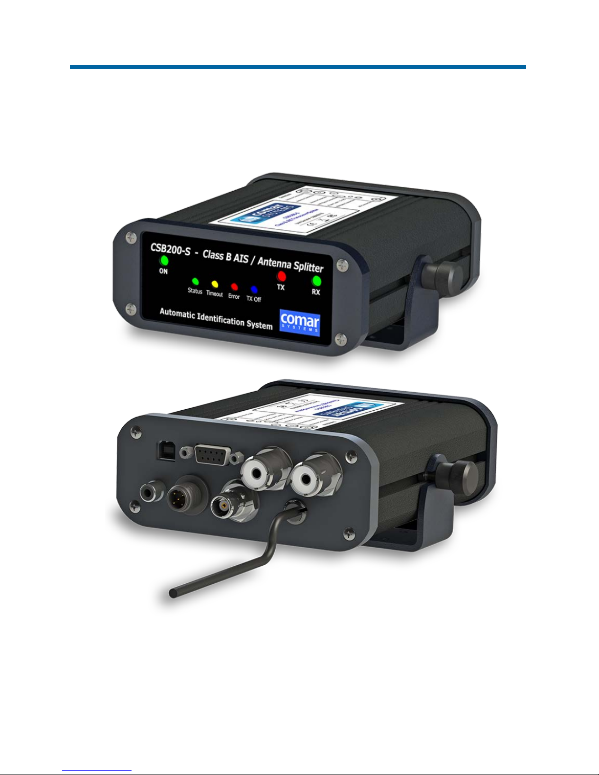
1 CSB200-S CLASS ‘B’ AIS TRANSPONDER
WITH ANTENNA SPLITTER
Page 6

CSB200-S
6
2 DOCUMENT
2.1 About This Manual
This manual provides installation, operating instructions and fault-finding procedures for the
equipment to which it relates.
After installation, this manual should remain with the vessel to which it relates.
This manual may also be made available in electronic Portable Document Format (PDF). In PDF
format, the following categories are all enabled as active hyperlink references: (1) The titles of each
section; (2) document cross-references; (3) the table of contents.
This document may therefore be navigated quickly and effectively by using a mouse or other pointing
device to activate each of these hyperlinks. This is a printer friendly document, designed to be
printed 2-sided as a booklet with A5 pages on A4 stock paper.
Document name: Date: Details: Author:
CSB200-S-MA-v01r01 2017-07-31 First draft MD, PC, AA
CSB200-S-MA-v02r01 2017-08-17 First revision - draft JLS, MW, AA
CSB200-S-MA-v02r02 2017-08-22 First Release (antenna port specifications added) JLS
Page 7

CSB200-S
7
3 NOTICE
3.1 Copyright
The copyright and all rights of a like nature in respect of this publication in any part of the world are
the property of COMAR SYSTEMS LTD. (COMAR).
No part of this document may be reproduced or transmitted in any form or by any means, whether
electronic, mechanical, photocopying, recording or otherwise, nor stored in any information retrieval
system of any kind, nor used for tendering or manufacturing, nor communicated to any other person
without the written permission of COMAR.
The recipient of this document, as its registered holder, must exercise due diligence in ensuring that
the above conditions are observed (Errors and Omissions Excepted).
Any enquires relating to this document or its contents should be addressed, in writing, in the first
instance to COMAR SYSTEMS LTD.
COMAR SYSTEMS
Vittlefields Technology Centre
Forest Road
NEWPORT
Isle of Wight
PO30 4LY
UNITED KINGDOM
tel:
+44 (0)1983 828900
email:
web:
www.comarsystems.com
COMAR SYSTEMS
reserves the right to make changes to its products and specifications without notice
Page 8

CSB200-S
8
4 GENERAL NOTICES
Please read the General Notices:
SAFETY: Make sure the power supply is switched off before you make any electrical
connections to the unit.
INSTALLATION: This equipment must be installed in accordance with the instructions
provided in this manual. Failure to do so could result in poor performance, personal injury
and/or damage to your vessel and/or connected equipment.
CABLES: The supplied cables should only be cut, shortened or lengthened by an
appropriate supplier.
COMPASS: The compass safe distance of this unit is 0.5 m or greater for 0.3° deviation.
In accordance with a policy of continual development and product improvement, hardware and
software may be upgraded from time to time, and future versions of equipment may therefore not
correspond exactly with this manual.
When necessary, upgrades to the product will be accompanied by updates or addenda to this
manual. Information contained in this manual is liable to change without notice.
COMAR SYSTEMS LTD. disclaims any liability for consequences arising from omissions or
inaccuracies in this manual and any other documentation provided with this product.
Page 9
CSB200-S
9
5 INTRODUCTION
The CSB200-S is a compact and rugged AIS Transponder with built-in Antenna Splitter, designed
for the demands of the small commercial boat, fishing boat and leisure markets. It meets the Class
‘B’ standard that allows vessels that are not required to fit Class ‘A’ units to voluntarily fit an AIS
Transponder. When connected to an external VHF antenna and a GPS antenna (not supplied), the
CSB200-S will transmit its own vessel position and data and also receive information from other AIS
vessels, shore stations and navigational aids within VHF range.
The CSB200-S has a built-in Antenna Splitter which allows the unit to share a single VHF antenna
with a VHF radiotelephone. This eliminates the need to install a second VHF antenna on the vessel
and reduces installation time and cost. Additionally, the unit has an FM radio output on the rear
which allows monitoring of public service FM radio broadcasts.
The unit is initially programmed by the user with the supplied software. The vessel’s MMSI number,
name, call sign, dimensions and type of vessel are entered at this stage. Once programmed, the
unit will automatically receive and transmit AIS data. The CSB200-S is compatible with a range of
computer-based navigation programs and chart plotters that are capable of accepting AIS data
sentences over a NMEA 0183 or NMEA 2000 connection.
This manual describes the installation and operation of the CSB200-S.
● It is recommended that your Transponder is installed by a professional installer
● Before operating the unit you should familiarise yourself with this user manual
5.1 Parts List
On delivery, carefully inspect the contents of the packing case. Note any damage or any missing
items. Ensure that the correct parts are included for your application.
*Note: RF Connectors:
Connector PL259 (male plug) will mate with connector SO239 (female socket)
Item: Description:
No.
included:
COMAR
SKU Number:
1 CSB200-S AIS Transponder/Splitter, with mounting bracket 1 001-1019
2 CSB200-S Installation CD 1 004-7043
3 CSB200-S Manual 1 003-1019
4 Data cable: 9-pin D-sub male connector to bare tails, 2 m 1 002-1002-1
5 USB cable: USB 2.0 Type A to Type B connectors 1 002-1006
6 VHF RF Patch lead: PL259-PL259 male connectors, 1 m* 1 004-7564
Page 10

CSB200-S
10
6 BACKGROUND TO AIS
The marine Automatic Identification System (AIS) is a location and vessel information reporting
system. It allows vessels equipped with AIS to automatically and dynamically share and regularly
update their position, speed, course and other information such as vessel identity with similarly
equipped craft. Position is derived from a Global Navigation Satellite System (GNSS
1
) network and
communication between vessels is by Very High Frequency (VHF) digital transmissions.
A sophisticated and automatic method of time sharing the radio channel is used to ensure that even
where a large number of vessels are in one location, blocking of individual transmissions is
minimised, any degradation of the expected position reporting interval is indicated to the user, and
even if the unit suffers extreme channel overload conditions it will always recover to normal operation.
6.1 AIS Classes
There are two classes of AIS unit fitted to vessels, Class ‘A’ and Class ‘B’. In addition AIS base
stations may be employed by the coastguard, port authorities and other authorised bodies. AIS units
acting as aids to navigation (AtoNs) can also be fitted to fixed and floating navigation markers such
as channel markers and buoys.
Class ‘A’ units are a mandatory fit under the safety of life at sea (SOLAS) convention to vessels
above 300 gross registered tons or which carry more than 11 passengers in International waters.
Many other commercial vessels and some leisure craft also fit Class ‘A’ units.
Class ‘B’ units are currently not a mandatory fit, but authorities in several parts of the world are
considering this. Class ‘B’ units are designed for fitting in vessels which do not fall into the mandatory
Class ‘A’ fit category.
● The CSB200-S is a Class ‘B’ unit.
6.2 Information Transmitted and Received
An AIS Class ‘B’ unit will transmit:
● MMSI
● Call Sign and Name
● Length and Beam
● Ship Type
● Time
● Course Over Ground (COG)
● Speed Over Ground (SOG)
● Heading
1
GPS is the American GNSS network. There are others, notably GLONASS (Globalnaya
Navigazionnaya Sputnikovaya Sistema) which is the Russian system and BDS (BeiDoü) which is the
Chinese system
Page 11
CSB200-S
11
In operation, an AIS unit uses one of two VHF channels within the international marine band
allocation (channel 87B, 161.975 MHz, or channel 88B, 162.025 MHz) to regularly transmit
information such as the vessel position, Maritime Mobile Service Identity (MMSI), Name, Speed,
Course, etc.
In operation, an AIS unit also receives similar information from other AIS equipped vessels within
VHF range and outputs that information for use by an external display medium (AIS enabled chart
plotter, computer using AIS enabled chart plotter software etc.)
7 INSTALLATION
7.1 Installation Warnings
WARNING: Do not connect the CSB200-S unit to a mains (line) AC electrical supply. An
electric shock or fire hazard could result.
CAUTION: Do not connect the CSB200-S unit to a dc supply exceeding 15.6V or reverse
the supply polarity. This may damage the unit.
CAUTION: The CSB200-S unit is designed for operation in the temperature range -25°C to
+55°C. Do not install (or use) the CSB200-S unit in environments which exceed this range.
CAUTION: The CSB200-S unit should be installed in a location where it is protected from
water and spray.
7.2 Mounting
The CSB200-S can be mounted to a suitable bulkhead or shelf.
● Select a location away from excessive heat sources
● Avoid high levels of vibration and shock
7.3 Power Connection
Connect a 12 V dc supply (9.6 - 15.6 V) capable of supplying 2 A peak to the dc power cable.
● Positive (+) = RED
● Negative (-) = BLUE
NOTE: The case of the unit is not isolated from the negative terminal of the supply; therefore it is not
recommended that the unit is attached to metal parts of the vessel.
Page 12
CSB200-S
12
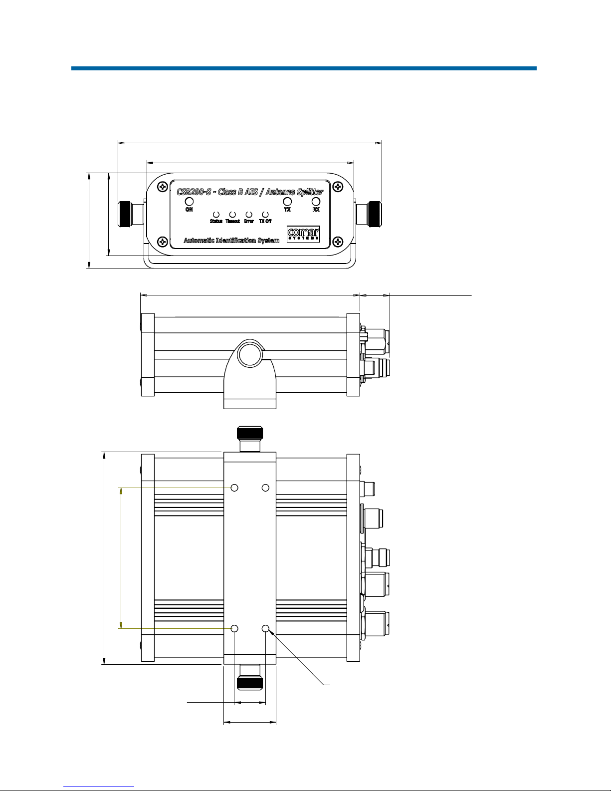
8 DIMENSIONS
86 CRS
32
19 CRS
86 CRS
129.5
4-HOLES TO SUIT
M4 FIXINGS
134
18 (ALLOW FOR CABLE)
126.5
50.5
161.2
58.25
Page 13

CSB200-S
13
8.1 GPS Antenna
The GPS antenna used for a Class ‘B’ AIS device must be a dedicated antenna, i.e. not shared with
any other GPS receiver.
Any NMEA GPS positional sentences transmitted as data from other equipment and connected to
the NMEA ports of the CSB200-S will not be used for AIS transmission.
The GPS antenna to be used must be of the active type, i.e. it should incorporate a low noise
amplifier (LNA) and be suitable for marine shipboard applications (index of protection, ruggedness,
means of mounting etc.) A GPS antenna should be selected so that there is a minimum total gain of
25 dB available at the antenna connector on the rear of the CSB200-S.
Installation of the GPS antenna is critical for the performance of the built in GPS receiver which is
used for timing of the transmitted time slots and for the supply of navigational information should
the main navigational GPS fail.
We strongly recommend that:
● The GPS antenna is mounted in an elevated position and free of shadow effect from the
ship’s superstructure.
● The GPS antenna has a free view through 360 degrees with a vertical angle of 5 to 90 degrees
above the horizon.
● As the received GPS signal is very sensitive to noise and interference generated by other
onboard transmitters, ensure that the GPS antenna is placed as far away as possible from
RADAR, Inmarsat® and Iridium® transmitters and ensure the GPS antenna is free from direct
view of the RADAR and the Inmarsat beam.
● It is important that the MF/HF and other VHF transmitter antennas are kept as far away as
possible from the GNSS antenna. It is good practice never to install a GPS antenna within a
radius of 5 metres from these antennas.
8.2 VHF Antenna
The CSB200-S with built-in Antenna Splitter can share a single VHF antenna with a VHF
radiotelephone. The VHF antenna should meet the following requirements:
● It must be suitable for marine shipboard applications (index of protection, ruggedness,
means of mounting, etc.)
● It should be omni-directional and vertically polarised with unity gain (0 dB) with a bandwidth
sufficient to maintain VSWR <1.5 over the frequency range 156 -163 MHz. As a minimum
the 3 dB bandwidth must cover the two AIS channels and the DSC Channel.
● It should be mounted with at least a two metre vertical separation distance from any other
VHF antenna used for speech or DCS communication.
Page 14

CSB200-S
14
9 PROGRAMMING THE TRANSPONDER
The ProAIS-2 application (supplied) allows you to configure and monitor the performance of your
CSB200-S. ProAIS-2 is compatible with both Microsoft® Windows® and Intel based Apple®
Macintosh® OS X operating systems. The system requirements are as follows:
● Microsoft® Windows® XP, Windows Vista, Windows 7, Windows 10 (32 and 64 bit)
● Apple® Macintosh® OS X 10.5 / 10.6 (Intel™ based systems only)
9.1 Installing the ProAIS-2 application
The application is installed from the CD provided with your CSB200-S transponder. Insert the CD
into your computer and navigate to the Windows or OS X folder.
● Windows: Double click the setup.exe item to start the installation and follow the on-screen
instructions.
● OS X: Double click the ProAIS-2.dmg item to start the installation and follow the on-screen
instructions.
9.2 Connecting to your CSB200-S
● Before launching the ProAIS-2 application, first connect your CSB200-S to your computer
using the USB cable. After it is connected, you can launch ProAIS-2 from the Windows Start
menu or the OS X Applications folder.
● Select the serial port corresponding to your CSB200-S from the drop down menu at the top
left of the ProAIS-2 window, and click the Connect button.
● ProAIS-2 is now communicating with your CSB200-S and will display any pre-configured
vessel data in the Configuration page.
9.3 The ProAIS-2 Application - Functions
The ProAIS-2 application has a number of pages with specific functions. These functions control the
setup of your CSB200-S.
● The Configuration page shows the current vessel information and CSB200-S configuration.
Vessel information and configuration can also be edited and saved to the CSB200-S.
● The GPS Status page shows the status and signal strength information for the AIS internal
GPS receiver.
● The Other Vessels page shows a list of AIS targets currently being received by the CSB200-S.
● The Diagnostics page shows a range of information relating to operation of the CSB200-S
which may be useful during installation.
● The Serial Data page shows real time data from the CSB200-S in NMEA 0183 format and
provides functions to record this data.
Page 15
CSB200-S
15
9.4 Configuring your CSB200-S
Please follow these steps to configure your CSB200-S AIS Transponder correctly:
1. Select the Configuration page to configure the AIS vessel data that will be transmitted by your
CSB200-S.
2. Enter your vessel’s name (20 characters maximum), call sign (optional, 7 characters maximum)
and MMSI number. An MMSI number is required for the CSB200-S to operate. The MMSI number
configured in your CSB200-S should be the same as that configured in any other radio
equipment on board. If you do not have an MMSI number contact the relevant authority in your
country for more information.
CAUTION: Once programmed, the MMSI number cannot be changed by the end user.
If the MMSI number needs to be changed in any way, the unit must be returned to
COMAR SYSTEMS or one of our authorised dealers
3. Select the vessel type most appropriate to your vessel from the drop down list.
4. Enter the dimensions of your vessel and the location of the GPS antenna in the Ship’s
Dimensions and GPS Antenna Location box. The dimensions should be entered in metres and
rounded up to the nearest whole metre (1 foot is approximately 0.3 metres
2
).
5. Save the configuration to your CSB200-S by clicking the Write Configuration button at the top
right of the configuration page. Please read the warning message and check the MMSI number
is correct before clicking the programme button.
6. Your CSB200-S is now fully configured and ready for use.
9.4.1 Important information for US Customers:
CAUTION: There are specific laws in the United States of America (US) regarding the
configuration of AIS Class ‘B’ transponders. If you are a US resident and intend to use your
CSB200-S in US waters, you should make sure that your retailer has configured your product
prior to supplying it to you. If your CSB200-S has not been pre-configured please contact
your dealer for details of how to have it configured.
WARNING: It is a violation of the rules of the Federal Communications Commission (FCC)
to input an MMSI number that has not been properly assigned to the end user, or to otherwise
input any inaccurate data in this device.
9.5 Optional User Configuration
The Configuration page includes additional options for NMEA port Baud rates and GPS data output.
2
1 imperial foot = 0.3048 metres
Page 16

CSB200-S
16
9.5.1 NMEA Baud Rate Configuration
Typically the NMEA Output Port 1 is used for connecting to a chart plotter or other display and is
configured to operate at 38,400 Baud. This rate is required for AIS data transfer.
Your CSB200-S provides a multiplex function between the NMEA Input Ports and the NMEA Output
Ports. Any data provided to the NMEA Input Ports will be multiplexed to the NMEA Output Ports
along with the AIS data. Typically the NMEA Input Port 2 is configured to operate at 4800 Baud for
connection to a Heading Sensor or other NMEA 0183 device.
The Configure Baud Rates box allows the Baud rates for the NMEA 0183 Ports to be adjusted
independently if required. After making changes to the Baud rate settings click the Write configuration
button to save these settings to your AIS transponder.
9.5.2 GPS Data Output
Your CSB200-S incorporates an internal GPS receiver and can be configured to output GPS position
fix information via the NMEA 0183 port. Check the GPS data sentences required in the Output GPS
Sentences box. After making changes to the GPS output settings click the Write configuration button
to save these settings to your CSB200-S.
9.5.3 GPS Status Page
The GPS status page shows the current GPS signal strength along with current GPS position fix
information. Satellite signals shown in green are actively being used to calculate a position. If a
position fix is not available then no position information will be displayed and the signal strength bars
will be shown in blue.
9.5.4 Other Vessels Page
The other vessels page provides a list of all AIS vessels from which AIS position reports are being
received. For each vessel the MMSI, Name, Call sign, AIS Class, Speed, Course, Latitude,
Longitude, Range and Bearing are shown along with the age (in seconds) of the position report. It
is possible to sort the displayed information by clicking on the column headings.
9.6 Optional Engineer Configuration
This information is provided for installation and diagnostic purposes only and
should not be relied upon for navigation.
9.6.1 Diagnostics Page
The diagnostics page provides a range of information about your CSB200-S operation and status.
This information may be useful during installation or when attempting to diagnose a potential issue
with the operation of your CSB200-S. If your CSB200-S is operating normally all items in the checklist
at the top left of the page will show a green tick / check mark.
Page 17

CSB200-S
17
9.6.2 Serial Data Page
The serial data page shows all data output from your CSB200-S in NMEA 0183 format. It is also
possible to send NMEA 0183 commands to the CSB200-S if required for technical support or custom
configuration. A facility to record the data to a file is provided by clicking the Log to File button.
9.6.3 Menu Bar
The application menu bar includes the following functions and features:
File Menu:
● Open log file - opens a previously recorded log file for review in ProAIS-2.
● Save log file - start recording data received from the connected CSB200-S to file.
● Exit - exits the ProAIS-2 application.
Options Menu:
● Alert on AIS transmission - a brief sound is output from your computer on each successive
AIS transmission.
Help Menu:
● About - shows ProAIS-2 application version and copyright information.
Page 18
CSB200-S
18
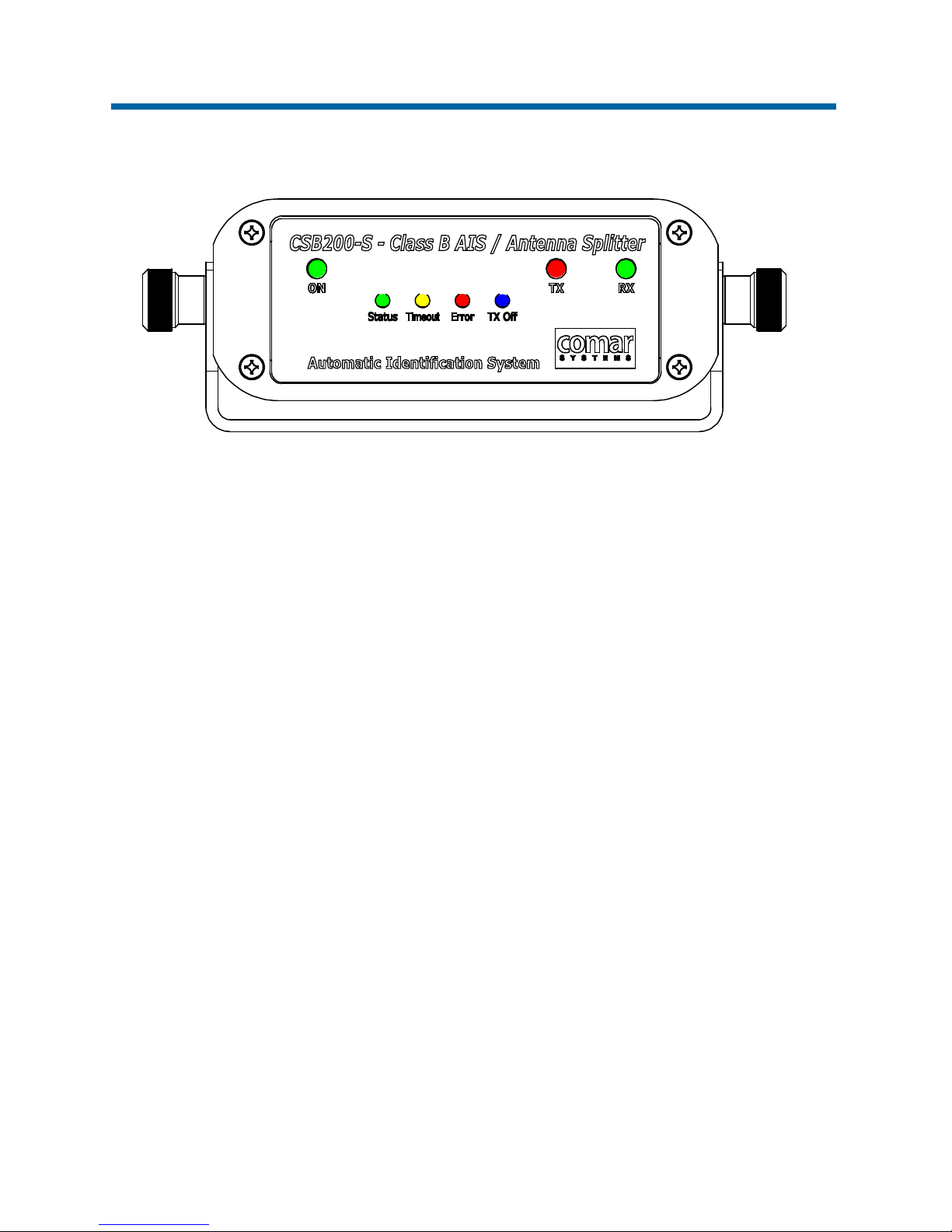
10 FRONT PANEL DISPLAY
11 OPERATION
11.1 Switching On
When the 12 V dc supply is switched ON then the green ON LED will light and the other six LEDs
visible on the front panel of the unit will illuminate twice for a period of one second on each
illumination. The Status, Error, TX Off and TX LEDs will then go out.
The green RX LED will flash when it is receiving data from other AIS units.
When the internal GPS is locked the yellow LED will go out and the green Status Led will light; note
that this process may take up to 30 minutes depending on the switch-on state of the GPS receiver.
The red TX LED will flash momentarily every time the unit transmits.
11.2 Warning and Fault States
If the unit has not been able to transmit a position report during the last expected two reporting
intervals (i.e. the nominal reporting interval cannot be maintained for operational reasons such as a
Message 23 quiet period, high channel load conditions, etc.) the yellow LED will illuminate. This is a
warning condition only and indicates that your vessels position is not currently being reported to
other vessels. Reception of other vessels AIS information by the CSB200-S is not affected. When the
unit is able to commence reporting the yellow LED will go out.
If a fault occurs then the red Error LED will illuminate. This may illuminate briefly if the power supply
is interrupted or if the VHF antenna characteristics are briefly affected.
If the red Error LED illuminates continuously then the unit should be assumed to be faulty and should
either be switched off (power removed) or if this is not practical, any other vessel position information
derived from the unit should not be used and it should also be assumed that the unit is not
Page 19

CSB200-S
19
transmitting valid position information for your vessel. The unit should be examined by an authorised
service agent at the earliest opportunity.
11.3 Data Port Messages
The data ports will output the following:
● (At power-up) boot-loader and main application splash text screens including version
numbers, and memory status
● Details of relevant AIS transmissions received
● Details of AIS transmissions sent
● Details of channel management messages received
● Alarm messages generated by the Built-In Integrity Testing (BIIT) function
The data ports will accept the following inputs:
● Programming information (USB)
● Alarm acknowledgements (NMEA)
11.4 AIS Transmit OFF
The Transmit OFF facility is provided in the event that you do not wish to disclose your position to
other users or to conserve power when it is not necessary to transmit your position.
The transmitter can be turned OFF by connecting a simple switch between the Blue core on pin 6
and the Green core on pin 5. Closing this switch will cause the Blue-TX off LED and the Yellow
Timeout LED to light, the Green Status LED will extinguish. Opening the switch will resume
transmissions. Reception of AIS data during this operation will not be affected.
11.5 Data Rates
The default Baud rate of the data link is 38.4 kBaud with 8 data bits, one stop bit and no parity. No
handshaking is used. The data interface conforms to IEC 61162-1.
11.6 Built in Test
The CSB200/S is equipped with Built-In Integrity Testing (BIIT). BIIT tests run continuously or at
appropriate intervals simultaneously with the standard functions of the equipment. The BIIT detects
any failure or malfunction that will significantly reduce integrity or stop operation of the CSB200-S
unit. The tests include:
● AIS TX malfunction (synthesiser not locked and TX time-out not exceeded)
● Antenna VSWR exceeds limit
● Rx channel 1 malfunction (synthesiser not locked)
● Rx channel 2 malfunction (synthesiser not locked)
Page 20

CSB200-S
20
● Internal GNSS (GPS) not in use
● No valid SOG information
● No valid COG information
● Background noise > -77dBm
● GPS failure
● VSWR exceeding the maximum allowed level
● The input voltage is out of the specified range
11.7 LED Indicators
ON This is a green LED which indicates, when lit, that power has been connected correctly to the
transponder.
Status This is a green LED which indicates, when lit, that the transponder hardware has been
configured, the operating software is present, the CPU has booted up, the application software is
running and everything is correct.
RX This is a green LED which indicates when flashing that the CSB200-S is receiving data from
other AIS transponders and is outputting this data as a VDM NMEA sentence on the output data
ports. If the Green LED is on continuously the unit has not been programmed with its personalised
data, it will still send received data to the output port but will not transmit.
TX This is a red LED which flashes momentarily when the CSB200-S transmits its own AIS data.
This is a yellow LED which indicates when lit that the transmitter is prevented from
transmitting. Reasons for this include the following:
● The transponder’s internal GPS receiver is not operating or is not yet ready
● The transponder was unable to transmit an AIS message due to the channel being already
occupied, e.g. by transmissions from other AIS transponders, or the TX Off function is in
operation
Error This is a red LED which indicates when lit, one of the following status conditions is possible:
● Transmitter lockout timer (1 second maximum) has operated
● GPS is unable to gain lock after 30 minutes
● VHF antenna VSWR is out of range
● Power Supply is out of range
● Background noise level is above the threshold level (-77dBm)
TX Off This is a blue LED which indicates that the remote TX Off switch has been operated to
manually stop the CSB200-S transmitting data.
Page 21
CSB200-S
21
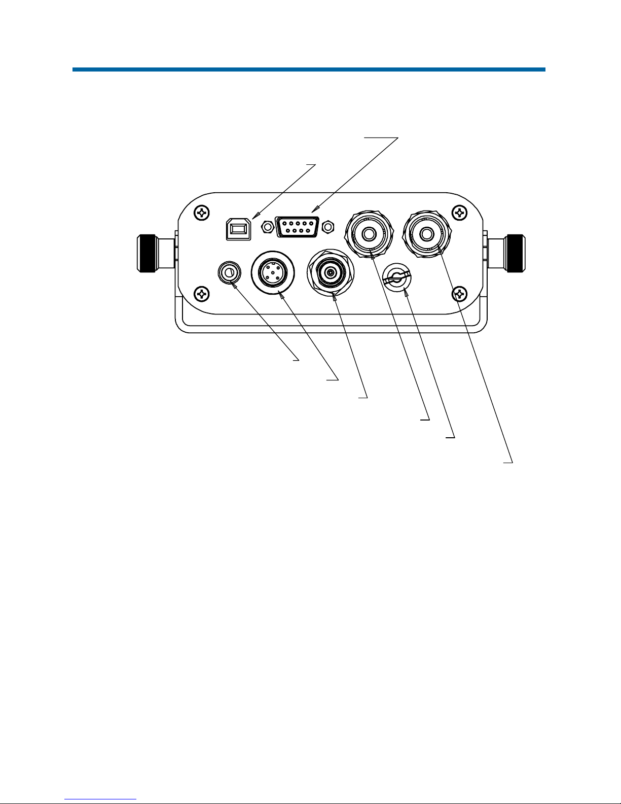
12 REAR CONNECTIONS
NMEA 2000 - Power & Data
S 239 V ntennaO - HF A
12 V dc Power Cable
S 239 VO - HF Radiotelephone
TNC Connector - GPS
USB 2.0
Type
‘B’ Connector
9-Way Sub
Data
- NMEA 0183D- Connector
Page 22
CSB200-S
22
13 DATA CONNECTION
If an external display unit is to be used to show other AIS units within range (such as a chart plotter,
computer serial terminal or other display device) then connect the correct tails of the data interface
cable to the display device. Note that the software in the display device must be configured for AIS
operation.
13.1 Connection to a computer
The CSB200-S may be connected to a computer using the USB cable supplied.
13.2 NMEA 0183 Connection
The data cable assembly to bare tails (provided) mates with the 9-pin D-type female connector
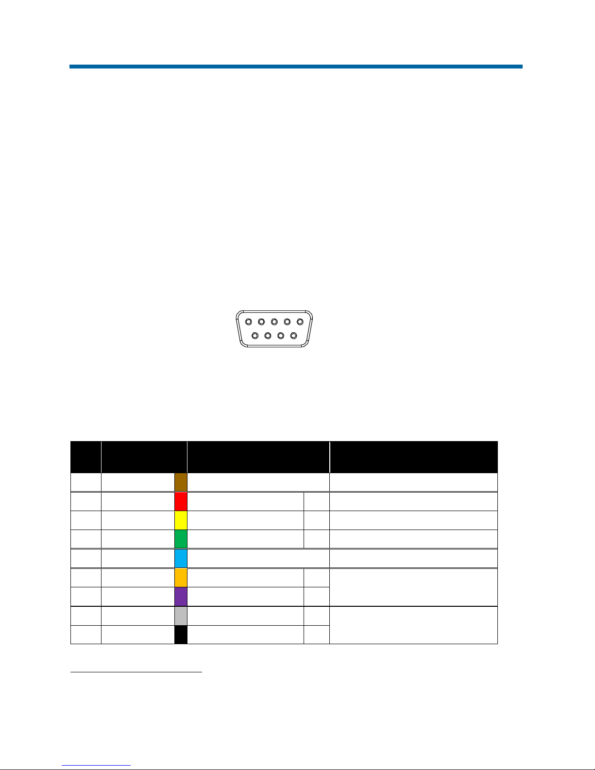
mounted at the rear of the CSB200-S. This cable is to be used for a NMEA 0183 connection
(IEC 61162-1).
13.2.1 Pin Identifications (by function)
The following table shows the pin identifications of the 9-way D-sub connector on the rear of the unit.
This connector handles the NMEA 0183 inputs and outputs:
3
With IEC 60757 colour abbreviations
Pin: Cable core colour3 Function: Description:
1 Brown, BR No connection -
2 Red, RD NMEA Output Port 1 (+) Default 38400 Baud
4 Yellow, YE NMEA Output Port 2 (+) Default 4800 Baud
5 Green, GN NMEA Output Ports 1 & 2 (–) NMEA Outputs Common (–)
6 Blue, BU AIS Transmission OFF Connect via external switch to pin 5
3 Orange, OG NMEA Input Port 2 (+)
Default 4800 Baud
7 Violet, VT NMEA Input Port 2 (–)
8 Grey, GY NMEA Input Port 1 (+)
Default 38400 Baud
9 Black, BK NMEA Input Port 1 (–)
1
5
6
9
9-Way D-Sub
Female Connection
Page 23
CSB200-S
23
13.2.2 Connection to a NMEA 0183 Plotter or Radar
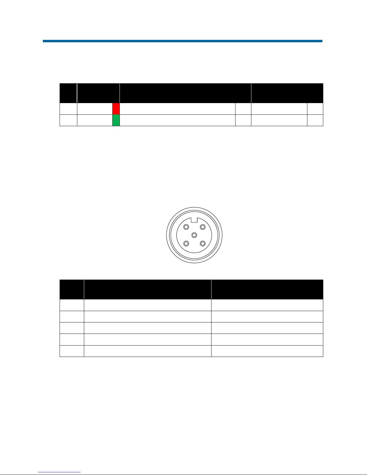
The CSB200-S may be connected to a chart plotter or a RADAR using the 9-way data cable supplied
and using the following connections:
Pin:
Cable core
colour
CSB200-S Connection: Plotter Connection:
2 Red, RD NMEA Output Port 1 (38400 Baud default) (+) NMEA Input (+)
5 Green, GN NMEA Output Port 1 (38400 Baud default) (–) NMEA Input (–)
13.3 NMEA 2000 Connection
For a NMEA 2000 connection (IEC 601162-3) a specialist drop cable will be required (not supplied).
This should be connected from the rear connector of the CSB200-S into the trunk of your existing
NMEA 2000 network. COMAR recommends that you obtain advice from a professional installer if a
NMEA 2000 installation is required.
Pin: NMEA 2000 Designation: Function:
1 Screen Screen (shield)
2 NET-S + 12 v dc
3 NET-C 0 v return
4 NET-H Data High (CAN-H)
5 NET-L Data Low (CAN-L)
1
3
4
5
2
5-Way NMEA 2000
Male Connection
Page 24

CSB200-S
24
13.4 Connection Summary
• To connect to a computer: Use the USB cable (supplied)
• To program the CSB200-S: Run the software ProAIS 2 which uses the USB connection
• To connect to a NMEA 2000 network: Use an industry-standard NMEA 2000 drop cable (not
supplied; seek specialist advice for this kind of connection)
• To connect to a NMEA 0183 compliant device: Use the 9-way data cable (supplied)
• To Disable AIS Transmission: Connect the BLUE wire of the 9-way data cable (pin 6) to the
GREEN wire of the data cable (pin 5) via a switch. The AIS transmissions will be re-enabled
when the switch is opened
14 MAINTENANCE
No scheduled maintenance is required. It is recommended to gently wipe away any accumulated
dust periodically. The CSB200-S contains no serviceable parts. Contact your local dealer if the unit
fails to function correctly.
WARNING: Unauthorised opening of the CSB200-S unit will invalidate the warranty.
CAUTION: Avoid using chemical solvents to clean the CBS200-S; solvents may damage the case
material.
Page 25
CSB200-S
25
15 SPECIFICATION
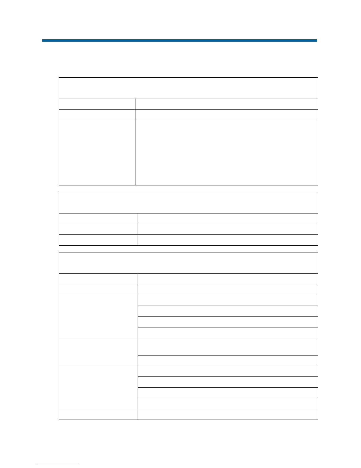
15.1 Physical
Dimensions: L 135 x W 128 x H 50 mm
Weight: 600 g
Connectors:
Power: 1 m 2-core captive cable
Antenna: SO239 UHF Connector
VHF Radiotelephone: SO239 UHF Connector
GPS Antenna: TNC Connector
FM Radio Out: RCA Phono Connector
Data In/Out: 9-pin D-sub Connector
NMEA 2000: 5-pin; 2x Data; 2x 12 V dc Power; 1x Shield
USB: USB 2.0 Type B Connector
15.2 Electrical
Power Supply: 12 V dc nominal; 9.6-15.6 V dc
Power Consumption: 4 W
Peak Power Rating: 2 A
15.3 Operational
Indicators: On, TX, RX, Status, TX Timeout, Error, TX Off
Internal GPS Receiver: RS232 38.4 KBaud bi-directional; RS422 38.4 KBaud bi-directional
GPS Antenna Port:
Impedance: 50 Ohms
Frequency: 1575 MHz
Gain: >20 dB including LNA
LNA bias voltage: 5 V dc max. 50 mA
Interal VHF Transponder:
Transmitter x 1; Receiver x 2
One receiver time shared between AIS and DSC
Frequency Range: 156.025 MHz to 162.025 MHz in 25 kHz steps
VHF Antenna Port:
Impedance: 50 Ohms
Frequency Range: 156 – 162 MHz
Gain: 3dBi nominal
VSWR: <2:1
Output Power: 33 dBm ± 1.5 dB
Page 26
CSB200-S
26
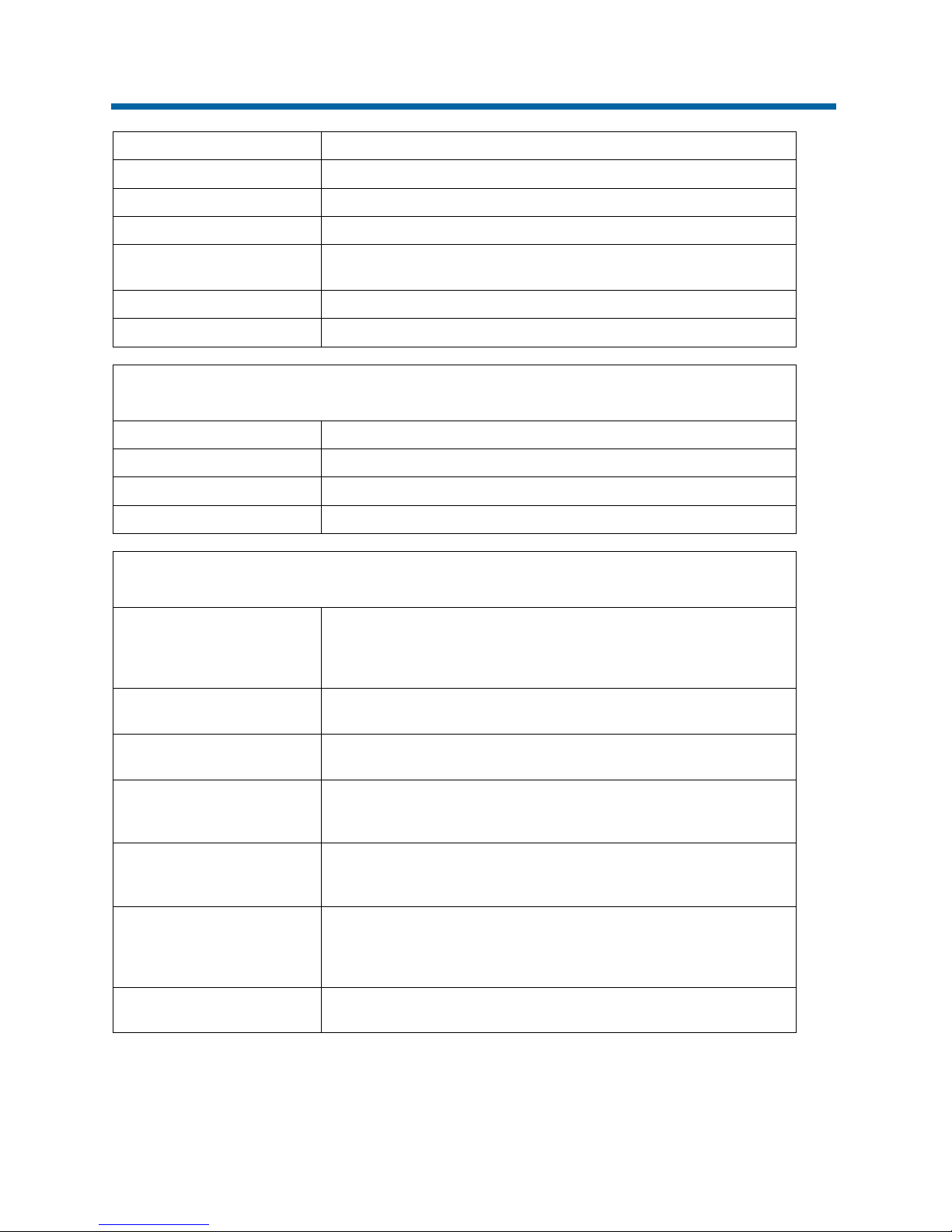
Channel Bandwith: 25 kHz
Channel Step: 25 kHz
Modulation Modes: 25 kHz GMSK (AIS, TX and RX); 25 kHz AFSK (DSC, RX only)
Bit Rate: 9600 b/s ±50 ppm (GMSK); 1200 b/s ±30 ppm (FSK)
RX Sensitivity:
Sensitivity – 107 dBm 25 kHz (Message Error Rate 20%); Co-Channel
10 dB; Adjacent Channel 70 dB; IMD 65 dB; Blocking 84 dB
Data Rates: 4800 Baud, 38400 Baud (software configurable)
NMEA 0183 messages: VDM, VDO, RMC, ACA, ACS, ALR, TXT and ACK
15.4 Environmental
Operating Temperature: -15°C to +55°C
Operating Humidity: Up to 93%
Storage Temperature: -20°C to +70°C
Compass: Safe distance 0.5 m
15.5 Approvals
IEC62287-1: 2006-03
Maritime navigation and radiocommunication equipment and systems Class ‘B’ shipborne equipment of the automatic identification system
(AIS) - Part 1: Carrier-sense time division multiple access (CSTDMA)
techniques
IEC60945: 2002-08
Maritime navigation and radiocommunication equipment and systems General requirements - Methods of testing and required test results
IEC61162-1
Maritime navigation and radiocommunication equipment and systems Digital interfaces - Part 1: Single talker and multiple listeners
IEC61108-1:
GLOBAL NAVIGATION SATELLITE SYSTEMS (GNSS) - Part 1: Global
positioning system (GPS) - Receiver equipment - Performance
standards, methods of testing and required test results
EN301 843-1v2.1
Electromagnetic compatibility and Radio spectrum Matters (ERM);
Electromagnetic Compatibility (EMC) standard for marine radio
equipment and services; Part 1: Common technical requirements
EN50383
Basic standard for calculation and measurement of electromagnetic field
strength and SAR related to human exposure from radio base stations
and fixed terminal stations for wireless telecommunications system
(110MHz-40GHz)
EN60950-1:
Information technology equipment - Safety - Part 1: General
requirements
This product complies with all the necessary standards under the European R&TTE directive for
Article 3.1(a), 3.1(b), 3.2 and 3.3(e). The above standards have been followed in pursuance of this.
Page 27
CSB200-S
27
16 VHF SHIP LICENCE
IMPORTANT: In most countries, the operation of an AIS unit is included under the vessels
marine VHF licence provisions. The vessel on which the AIS unit is to installed must therefore
possess a current VHF radiotelephone licence which lists the AIS system and the vessel Call Sign
and MMSI number. Please contact the relevant authority in your country for more information.
17 DECLARATION OF CONFORMITY
COMAR SYSTEMS LTD. of Vittlefields Technology Centre, Forest Road, Newport, Isle of Wight,
PO30 4LY, United Kingdom, hereby declares that the CSB200-S is in compliance with the essential
requirements and other relevant provisions of EC Directive 1999/5.
This product carries the CE mark, notified body number and alert symbol as required by the R&TTE
directive.
18 FCC NOTICE
WARNING: It is a violation of the rules of the Federal Communications Commission to input
an MMSI that has not been properly assigned to the end user, or to otherwise input any
inaccurate data into this device. The MMSI and Static Data in this transponder must be configured
by the vendor of the device or by an appropriately qualified person in the business of installing
marine communications equipment on board vessels. In no event shall the entry of static data into
this Class ‘B’ device be performed by the end user. Knowingly programming a Class ‘B’ device with
inaccurate static data, or causing a Class ‘B’ AIS to be programmed with inaccurate static data, is
prohibited.
Page 28

CSB200-S
28
19 GENERAL WARNINGS
All marine Automatic Identification System (AIS) units utilise a satellite based system such as the
Global Positioning Satellite (GPS) network or the Global Navigation Satellite System (GLONASS)
network to determine position. The accuracy of these networks is variable and is affected by factors
such as the antenna positioning, how many satellites are used to determine a position and how long
satellite information has been received for.
It is desirable wherever possible therefore to verify both your vessel’s AIS derived position data and
other vessels AIS derived position data with visual or RADAR based observations.
19.1 VHF Antenna Connection
Connecting a badly mismatched VHF antenna, leaving the VHF antenna port disconnected, or
shorting the VHF antenna port will activate the VSWR alarm, cause the unit to stop sending position
reports or cause damage to the transponder.
19.2 Radio Frequency Exposure
To meet the requirements for Radio Frequency Exposure it is necessary to install the VHF antenna
correctly and operate the AIS equipment according to the instructions.
The VHF antenna must be mounted at a minimum distance (vertical separation) of 3 metres from
the head of any person standing on deck in order to meet international safety directives on Maximum
Permissible Exposure (MPE) / Specific Absorption Rate (SAR).
Where no suitable structure exists to achieve a 3 metre vertical separation then the antenna base
must be mounted at least 1 metre above the head of any person within range, all persons should
stay outside the 3 metre safety radius and if practical, a grounded RF shield should be interposed
between people and the antenna.
Failure to adhere to these limits could expose persons within the 3 metre radius to RF radiation in
excess of the MPE / SAR limits.
Page 29

CSB200-S
29
20 LIMITED WARRANTY
COMAR SYSTEMS LTD. warrants this product to be free from defects in materials and manufacture
for one year from the date of purchase. Comar Systems Ltd will, at its sole discretion, repair or
replace any components that fail in normal use. Such repairs or replacement will be made at no
charge to the customer for parts and labour. The customer is, however, responsible for any
transportation costs incurred in returning the unit to COMAR SYSTEMS LTD.
This warranty does not cover failures due to abuse, misuse, accident or unauthorised alteration or
repairs. This does not affect the statutory rights of the consumer.
Page 30

CSB200-S
30
21 DISCLAIMER
● COMAR SYSTEMS LTD. is not responsible for damages or injuries caused by your use of,
or inability to use the CSB200-S correctly. The CSB200-S is intended for use only by persons
trained in navigation and only as a navigational aid, not as the sole method of navigation.
● COMAR SYSTEMS LTD. disclaims any liability for consequences arising from omissions or
inaccuracies in this manual and any other documentation provided with this product.
● Every effort has been made to ensure that all information contained in this manual is accurate
at the time of going to press.
● We advise that you take normal steps to ensure that you have the most up to date product
information.
Page 31

CSB200-S
31
Page 32

See, be seen, be safe at sea
COMAR SYSTEMS LTD.
Vittlefields Technology Centre
Forest Road
NEWPORT
Isle of Wight
PO30 4LY
UNITED KINGDOM
tel: +44 (0)1983 82
8900
email:
web: www.
comarsystems.com
 Loading...