

Page 1
IGS-NT Safety Manual 1.0 rev.8
Page 1 of 7
IGS-NT-1.0 – Safety Manual / ©ComAp – March 2014 / IGS-NT-1.0-SafetyManual rev.8.pdf
ComAp, a s.
Kundratka 2359/17
180 00 Praha 8
Czech Republic
ISO 9001 Certified
C
o
m
A
p
s
.
r
.
o
.
Q
u
a
l
i
t
y
M
a
n
a
g
e
m
e
n
t
Tel.: +420 246012111
Fax: +420 2 66316647
E-mail: info@comap.cz
Internet: http://www.comap.cz
IGS-NT Safety manual
This document shall provide the detail description for customers of ComAp paralleling controllers, namely for
IGS-NT line members (controllers named in the following bullets) how to connect the controller and coherent
systems, to comply with VDE-AR-N-4105 requirements, namely with the requirement for Single fault
tolerance.
This manual is dedicated for following ComAp controllers:
· IG-NT-BB
· IG-NTC-BB
· IS-NT-BB
· IS-NTC-BB
· IM-NT-BB
· IM-NTC-BB
· AIO-NT-BB
· AIO-NTC-BB
and all these controllers are generally named as a “controller” in this document.
Hint:
On all the schemes shown below, it is assumed, that:
· All binary outputs are activated as low side switches, it means in active state the BO provides minus
pole of the controller power supply.
· All binary inputs are active when minus pole of the controller power supply is applied to input
terminal.
In case the logic on particular installation (site) is opposite (e.g. binary outputs are high side switch type) the
corresponding change has to be taken into account in the scheme as well (interchange between L- and L+
terminals). Due to better readability of the schemes this change is not shown.
In the text below there is referred about circuit breakers, CB. These CB are meant as the 2 redundant CB
which the norm VDE-AR-N 4105 requires. Based on the target application – SPI, SPtM or MGCB the
redundant breakers are either GCB1 and GCB2 in case of SPI and SPtM application, or MGCB1 and
MGCB2 in case of MGCB application. Due to this variability the redundant breakers are referred as CB and
based on the target application this means either GCB or MGCB.
Single Fault Tolerance requirement
VDE-AR-N 4105:2011-08 requests in point A.6 that central NS protection, integrated interface switch as well
as the trigger circuit consisting of integrated NS protection and integrated interface switch shall meet the
requirements for single-fault tolerance.
This requirement can not be achieved with any single controller mentioned above therefore 2 independent
devices (or units) have to be used instead of just one controller.
There are following possibilities:
1. ComAp controller (mentioned above) plus MainsPro controller (independent mains protection unit).
Page 2
IGS-NT Safety Manual 1.0 rev.8
Page 2 of 7
IGS-NT-1.0 – Safety Manual / ©ComAp – March 2014 / IGS-NT-1.0-SafetyManual rev.8.pdf
ComAp, a s.
Kundratka 2359/17
180 00 Praha 8
Czech Republic
ISO 9001 Certified
C
o
m
A
p
s
.
r
.
o
.
Q
u
a
l
i
t
y
M
a
n
a
g
e
m
e
n
t
Tel.: +420 246012111
Fax: +420 2 66316647
E-mail: info@comap.cz
Internet: http://www.comap.cz
Breakers control according to VDE-AR-N 4105
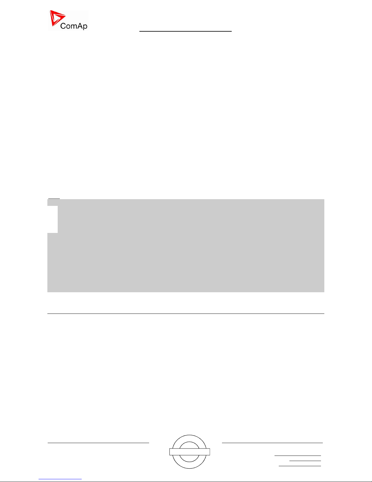
In SPI applications, there are controlled 2 redundant GCB breakers, based on the following picture - Pict. 1.
Controller behaves as a NS protection system and in case of network failure it trips both GCB1 and GCB2.
Gen
Engine
Mains / Network
GCB1 GCB2
Pict. 1. SPI application with control of 2 redundant breakers, according to VDE-AR-N 4105
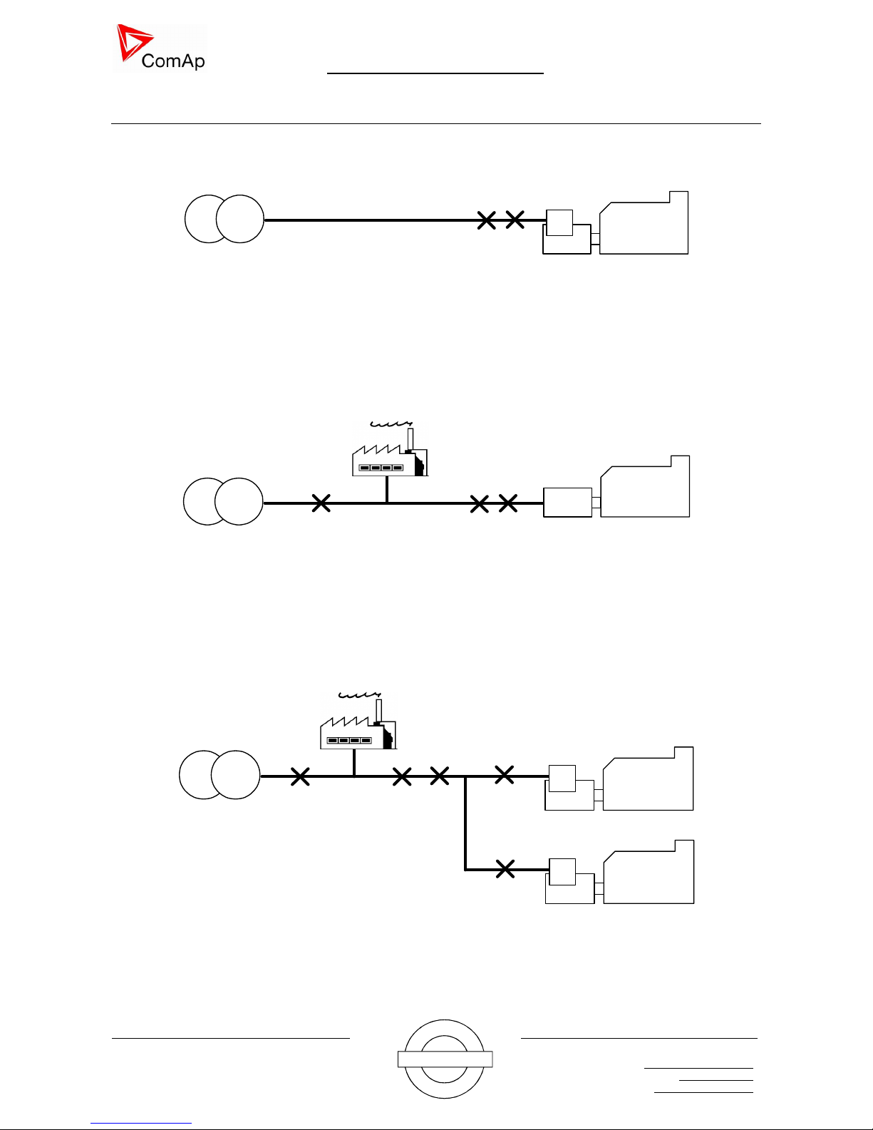
In SPtM application there are controlled 2 redundant GCBs and 1 MCB. The breaker redundancy
requirement of the VDE-AR-N 4105 is created with the GCB breakers to ensure the gen-set is disconnected
from network and any remaining customer system as 4105 requires. Controller behaves as a NS protection
system and in case of network failure it trips both GCB1 and GCB2.
Mains / Network
Load
MCB
GCB1 GCB2
Gen
Engine
Pict. 2. SPtM application with control of 2 redundant breakers according the VDE-AR-N 4105
In complex applications, InteliMainsNT controller has to be used, MGCB application and the breaker
redundancy requirement of the VDE-AR-N 4105 is created with the MGCB breakers to ensure the standby
function of the solution. Controller behaves as a NS protection system and in case of network failure it trips
both MGCB1 and MGCB2.
Gen
Engine
Mains / Network
MCB
Load
MGCB1
Gen
Engine
GCB1
GCB2
MGCB2
Pict. 3. MINT application with control of 2 redundant breakers using InteliMainsNT controller
Page 3
IGS-NT Safety Manual 1.0 rev.8
Page 3 of 7
IGS-NT-1.0 – Safety Manual / ©ComAp – March 2014 / IGS-NT-1.0-SafetyManual rev.8.pdf
ComAp, a s.
Kundratka 2359/17
180 00 Praha 8
Czech Republic
ISO 9001 Certified
C
o
m
A
p
s
.
r
.
o
.
Q
u
a
l
i
t
y
M
a
n
a
g
e
m
e
n
t
Tel.: +420 246012111
Fax: +420 2 66316647
E-mail: info@comap.cz
Internet: http://www.comap.cz
Option 1 - use MainsPro relay
For any application shown above on the Pict. 1, or Pict. 2, or Pict. 3 the concept of 2 independent units can
be used.
MainsPro sw version 1.4.1, hw version: 1.2 is independent ComAp protection relay which measures network
voltage and frequency and trips the supervised CB in case network values are not within adjusted limits.
In this concept, 2 independent units are used - controller and MainsPro unit. The primary breaker is
controlled directly from the controller; the secondary breaker (redundant) is controlled from the controller
through MainsPro unit.
Once controller detects network parameters out of limits, it trips the primary circuit breaker and
simultaneously gives a command to the MainsPro unit to trip the secondary circuit breaker.
Once the MainsPro relay detects network parameters out of limits, it trips the secondary circuit breaker and
simultaneously gives a signal to controller to trip the primary circuit breaker.
This interconnection ensures, that both breakers are tripped in every case the network parameters are out of
limits and also both the controller and MainsPro relay are tested every case the network parameters are out
of limits. In case any of the units fail, the alarm: GCB fail or MGCB fail occurs (In case MainsPro relay fail,
controller will detect redundant CB fail due to non receiving change on the redundant CB feedback. In case
controller fails to open the primary CB, it will detect the primary CB fail due to non receiving change on the
primary CB feedback signal)
Wiring instructions of this concept:
· Signals for control of primary CB has to be configured to any physical binary outputs 1 – 8 of the
controller.
· Signals for control of redundant CB has to be configured to any physical binary output 9-16 (9-12
based on the controller hardware) of the controller and connected to Tripping input of the MainsPro
unit – BI1 Ext Trip.
· Signals for both primary and secondary CB feedback has to be configured to any binary input of the
controller.
· Signal from MainsPro relay, signalizing that the CB shall be tripped has to be connected to the
Controller, LBI: Ext MP Trip.
· All these signals are already prepared in default archives and there is no need to configure anything
in relation to this interconnection.
Controller and MainsPro relay have to be connected as follows:
Page 4

IGS-NT Safety Manual 1.0 rev.8
Page 4 of 7
IGS-NT-1.0 – Safety Manual / ©ComAp – March 2014 / IGS-NT-1.0-SafetyManual rev.8.pdf
ComAp, a s.
Kundratka 2359/17
180 00 Praha 8
Czech Republic
ISO 9001 Certified
C
o
m
A
p
s
.
r
.
o
.
Q
u
a
l
i
t
y
M
a
n
a
g
e
m
e
n
t
Tel.: +420 246012111
Fax: +420 2 66316647
E-mail: info@comap.cz
Internet: http://www.comap.cz
Pict. 4. Block scheme how to connect the Controller and MainsPro unit, in case contactor is used for GCB
control – in SPI or SPtM application. For MGCB application the scheme is identical but instead of GCB the
MGCB signals are used.
Page 5

IGS-NT Safety Manual 1.0 rev.8
Page 5 of 7
IGS-NT-1.0 – Safety Manual / ©ComAp – March 2014 / IGS-NT-1.0-SafetyManual rev.8.pdf
ComAp, a s.
Kundratka 2359/17
180 00 Praha 8
Czech Republic
ISO 9001 Certified
C
o
m
A
p
s
.
r
.
o
.
Q
u
a
l
i
t
y
M
a
n
a
g
e
m
e
n
t
Tel.: +420 246012111
Fax: +420 2 66316647
E-mail: info@comap.cz
Internet: http://www.comap.cz
Pict. 5 . Block scheme how to connect the Controller and MainsPro unit, in case circuit breaker is used for
GCB control – in SPI or SPtM application. For MGCB application the scheme is identical but instead of GCB
the MGCB signals are used.
This means, that both units serve as independent units and so each of them measures independently the
Mains parameters and in case the out of range is detected, both CB are tripped.
Page 6

IGS-NT Safety Manual 1.0 rev.8
Page 6 of 7
IGS-NT-1.0 – Safety Manual / ©ComAp – March 2014 / IGS-NT-1.0-SafetyManual rev.8.pdf
ComAp, a s.
Kundratka 2359/17
180 00 Praha 8
Czech Republic
ISO 9001 Certified
C
o
m
A
p
s
.
r
.
o
.
Q
u
a
l
i
t
y
M
a
n
a
g
e
m
e
n
t
Tel.: +420 246012111
Fax: +420 2 66316647
E-mail: info@comap.cz
Internet: http://www.comap.cz
Appendix
Parameters for Circuit Breakers
To be able to reach requested timing as per VDE-AR-N-4105, CB has to be able to open contacts within
80ms from deactivation. Our concept supposed to use 100ms reaction time for control equipment reaction
and 80ms is time dedicated for CB reaction.
You have to use a reliable Circuit Breaker with known reliability and this Circuit breaker has to have contacts
constructed in the way which avoid false feedback indication in case of any failure. Circuit breaker has to be
design for compliance with VDE-AR-N 4105.
Example could be e.g. Schneider Electric NSX, NS and NW family or ABB Tmax or Emax family, plus many
others.
Commissioning
The safety functions, created by:
· Combination of controller and MainsPro relay
has to wired per instructions above and shall be tested prior connection of the plant to the network.
Test of MainsPro relay:
· Activate BI: 1 Ext Trip on the MainsPro. MainsPro terminal number 24 shall change its state.
· Deactivate BI:1 Ext Trip on the MainsPro. MainsPro terminal number 24 shall change its state to
original value.
Test of MainsPro relay is done by every closing and opening of the CB2. In case MainsPro relay fails,
controller issue alarm: GCB fdb S fail and trips the plant from network, type of protection Shutdown.
Safety functions has to be checked during commissioning and record has to be made about this test.
Then, customer has to establish period for periodic testing.
Page 7

IGS-NT Safety Manual 1.0 rev.8
Page 7 of 7
IGS-NT-1.0 – Safety Manual / ©ComAp – March 2014 / IGS-NT-1.0-SafetyManual rev.8.pdf
ComAp, a s.
Kundratka 2359/17
180 00 Praha 8
Czech Republic
ISO 9001 Certified
C
o
m
A
p
s
.
r
.
o
.
Q
u
a
l
i
t
y
M
a
n
a
g
e
m
e
n
t
Tel.: +420 246012111
Fax: +420 2 66316647
E-mail: info@comap.cz
Internet: http://www.comap.cz
Mandatory settings of network protections in controller and MainsPro
The following tables determine the network protections parameters, which have to adjusted in the controller
and in MainsPro (in case MainsPro is used). After parameters adjustment the change of parameters has to
be disabled – either by password in case of controller or mechanical seal in case of MainsPro.
Controller
Groupe Name of setpoint Value
Mains protect Mains <V MP 80%
Mains >V MP 115%
Mains >f 51.5Hz
Mains <f 47.5Hz
Mains Avg>V MP 110%
MainsProtDel 0s
Protect type LOW VOLT
Sync/Load ctrl MainsSyncVMax 110%
MainsSyncVMin 85%
MainsSyncFmax 50,05Hz
MainsSyncFmin 47.50Hz
MainsSyncTShrt 5s
MainsSyncTLong 60s
Slow Load ramp 600s
MainsPro
Groupe
Name of
setpoint Value
Note
U<> U> 115%
Value has to be set in absolute value. So
have to be calculated from NominalVoltage
and percentage at Value column
U>Del 0.00s
U< 80%
Value has to be set in absolute value. So
have to be calculated from NominalVoltage
and percentage at Value column
Avg U> 110%
Value has to be set in absolute value. So
have to be calculated from NominalVoltage
and percentage at Value column
F<> f> 51.50Hz
f>Del 0.00s
f< 47.50Hz
f<Del 0.00s
f(BI) f(BI1) Ext
f(RE) f(RE1) !CommTrpPer
f(RE2) !Internfail
f(RE3) U Sig
f(RE4) F Sig
 Loading...