

Page 1

InteliSys-NTC
Hybrid
Hybrid Master Controller
SW version 2.2.0
1 Document information 6
2 System overview 10
3 Installation and wiring 13
4 Controller setup 26
5 Technical data 157
6 Appendix 158
Copyright © 2020 ComAp a.s.
Written by Vladimír Zubák
Prague, Czech Republic
ComAp a.s., U Uranie 1612/14a,
170 00 Prague 7, Czech Republic
Tel: +420 246 012 111
E-mail: info@comap-control.com, www.comap- control.com
Global Guide
Page 2

Table of contents
1 Document information 6
1.1 Clarification of Notation 6
1.2 About this guide 6
1.3 Legal notice 6
1.4 Dangerous voltage 8
1.4.1 Adjust the setpoints 8
1.5 Document history 8
1.6 Firmware and Archives 9
1.6.1 BaseBox type controllers 9
2 System overview 10
2.1 What is a Hybrid application? 10
2.1.1 How do ComAp controllers support Hybrid applications? 10
2.1.2 How the InteliSys NTC Hybrid controller works? 11
2.2 Configurability and monitoring 11
2.2.1 GenConfig 11
2.2.2 InteliMonitor 12
2.2.3 WinScope 12
2.2.4 WebSupervisor 12
3 Installation and wiring 13
3.1 General 13
3.1.1 Wiring 13
3.1.2 Grounding 14
3.1.3 Power supply 14
3.1.4 Power supply fusing 15
3.1.5 Voltage and current inputs 15
3.2 InteliSys NTC Hybrid Installation Instructions 16
3.2.1 Mounting 16
3.2.2 Terminal diagram, Dimensions 18
3.2.3 Package contents 18
3.2.4 Jumper settings 19
3.3 Binary Input wiring 19
3.4 Binary Output wiring 20
3.4.1 IM-NT-BB and IM-NTC-BB 20
3.5 Analog Input and Output wiring 21
3.6 CAN and RS485 bus wiring 23
InteliSys-NTC Hybrid 2.1.0 Global Guide
2
Page 3

3.6.1 Wiring examples 24
4 Controller setup 26
4.1 Connection to a controller usingPC 26
4.1.1 Direct connection 26
4.1.2 Modem connection 27
4.1.3 Internet connection 28
4.1.4 Airgate connection 29
4.1.5 Connection to multiple controllers 29
4.2 Modification of configuration, setpoints etc 30
4.3 Programming of a controller 31
4.3.1 Standard programming 31
4.3.2 Programming of non-responsive controller 32
4.4 Changing the language 34
4.4.1 Selection of the language in InteliSysNTC Hybrid 34
4.5 Password management 35
4.5.1 User administration 35
4.5.2 Access group setting in GenConfig 36
4.5.3 Password break protection 37
4.6 Related tools 37
4.7 Functions 39
4.7.1 Overview 40
4.7.2 Modes 54
4.7.3 Process Limitation 58
4.7.4 System start 64
4.7.5 StartUpSynchronization 65
4.7.6 Power management 65
4.7.7 Dynamic Spinning Reserves 97
4.7.8 Remote Alarm Messaging 97
4.7.9 Controller Redundancy 99
4.7.10 System load control modes 100
4.7.11 Managing system load control modes 103
4.7.12 Renewables Active Power Control 108
4.7.13 Renewables Reactive Power Control 111
4.7.14 Multiple Mains Feeders Support 113
4.7.15 System PF control modes 115
4.7.16 Automatic Mains Failure function 117
4.7.17 Regulation loops 119
4.7.18 Force value – step by step guide 121
4.7.19 Values for continuous writing from external sources 123
InteliSys-NTC Hybrid 2.1.0 Global Guide
3
Page 4

4.7.20 General Purpose Timers 124
4.7.21 History Related functions 125
4.7.22 User Buttons 127
4.7.23 Remote Control Function 128
4.7.24 Virtual Peripheral Inputs-Outputs (VPIO) module 129
4.7.25 Shared Inputs and Outputs 129
4.7.26 Distributed Binary Inputs and Outputs 131
4.7.27 MODBUS 132
4.7.28 Analog Input Sensors and User Sensors 134
4.7.29 Languages and Translator tool in GenConfig 134
4.7.30 System Start/Stop 135
4.7.31 Power Formats 135
4.7.32 Soft Unload with support of IAux measurement 136
4.7.33 System Isolated 138
4.7.34 User Mask function 138
4.7.35 Switchable Current measurement ratio 139
4.7.36 PLC functions 139
4.8 Renewables Interface 139
4.8.1 Required communication lines 139
4.8.2 Configuration for communication with the InteliFieldbus Gateway 140
4.9 Protections and Alarm management 142
4.9.1 Supported protections 142
4.9.2 Protection groups 143
4.9.3 Protection types 143
4.9.4 Default protections in MCB/MGCB applications 144
4.9.5 Mains voltage and frequency protections - limits and indications 144
4.9.6 Bus voltage and frequency protections - limits and indications 145
4.9.7 User configurable protections 146
4.9.8 Reset Actual Alarms selection 148
4.9.9 Bus Measurement Error detection 149
4.9.10 Peripheral Modules Error detection 149
4.10 MGCB/MCB fail detection 149
4.10.1 MCB fail Information 149
4.10.2 General Information 150
4.10.3 Function for breaker control in AUT mode 155
4.10.4 Function for breaker control in MAN mode 155
4.11 Controller operation states 156
5 Technical data 157
InteliSys-NTC Hybrid 2.1.0 Global Guide
4
Page 5

6 Appendix 158
Controller objects 159
6.1 List of controller objects types 159
6.1.1 Setpoints 160
6.1.2 Values 349
6.1.3 Logical binary inputs 415
6.1.4 Logical binary outputs 462
6.1.5 Logical analog inputs 500
InteliSys-NTC Hybrid 2.1.0 Global Guide
5
Page 6

1 Document information
1.1 Clarification of Notation 6
1.2 About this guide 6
1.3 Legal notice 6
1.4 Dangerous voltage 8
1.5 Document history 8
1.6 Firmware and Archives 9
1.1 Clarification of Notation
Note: This type of paragraph calls the reader’s attention to a notice or related theme.
IMPORTANT: This type of paragraph highlights a procedure, adjustment etc., which can cause a
damage or improper function of the equipment if not performed correctly and may not be clear at
first sight.
Example: This type of paragraph contains information that is used to illustrate how a specific function
works.
1.2 About this guide
Pressing F1 in the GenConfig and InteliMonitor Setpoints, Values or configuration window will open the help
with the context of currently selected Setpoint, value and binary input or output function.
1.3 Legal notice
This End User's Guide/Manual as part of the Documentation is an inseparable part of ComAp’s Product and
may be used exclusively according to the conditions defined in the “END USER or Distributor LICENSE
AGREEMENT CONDITIONS – COMAP CONTROL SYSTEMS SOFTWARE” (License Agreement) and/or in
the “ComAp a.s. Global terms and conditions for sale of Products and provision of Services” (Terms) and/or in
the “Standardní podmínky projektů komplexního řešení ke smlouvě o dílo, Standard Conditions for Supply of
Complete Solutions” (Conditions) as applicable.
ComAp’s License Agreement is governed by the Czech Civil Code 89/2012 Col., by the Authorship Act
121/2000 Col., by international treaties and by other relevant legal documents regulating protection of the
intellectual properties (TRIPS).
The End User and/or ComAp’s Distributor shall only be permitted to use this End User's Guide/Manual with
ComAp Control System Registered Products. The Documentation is not intended and applicable for any other
purpose.
Official version of the ComAp’s End User's Guide/Manual is the version published in English. ComAp reserves
the right to update this End User's Guide/Manual at any time. ComAp does not assume any responsibility for its
use outside of the scope of the Terms or the Conditions and the License Agreement.
Licensed End User is entitled to make only necessary number of copies of the End User's Guide/Manual. Any
translation of this End User's Guide/Manual without the prior written consent of ComAp is expressly prohibited!
InteliSys-NTC Hybrid 2.1.0 Global Guide
6
Page 7

Even if the prior written consent from ComAp is acquired, ComAp does not take any responsibility for the
content, trustworthiness and quality of any such translation. ComAp will deem a translation equal to this End
User's Guide/Manual only if it agrees to verify such translation. The terms and conditions of such verification
must be agreed in the written form and in advance.
For more details relating to the Ownership, Extent of Permitted Reproductions Term of Use of the
Documentation and to the Confidentiality rules please review and comply with the ComAp’s License
Agreement, Terms and Conditions available on www.comap-control.com.
Security Risk Disclaimer
Pay attention to the following recommendations and measures to increase the level of security of ComAp
products and services.
Please note that possible cyber-attacks cannot be fully avoided by the below mentioned recommendations and
set of measures already performed by ComAp, but by following them the cyber-attacks can be considerably
reduced and thereby to reduce the risk of damage. ComAp does not take any responsibility for the actions of
persons responsible for cyber-attacks, nor for any damage caused by the cyber-attack. However, ComAp is
prepared to provide technical support to resolve problems arising from such actions, including but not limited to
restoring settings prior to the cyber-attacks, backing up data, recommending other preventive measures against
any further attacks.
Warning: Some forms of technical support may be provided against payment. There is no legal or factual
entitlement for technical services provided in connection to resolving problems arising from cyber-attack or
other unauthorized accesses to ComAp's Products or Services.
General security recommendations and set of measures
1. AccessCode
• Change the AccessCode BEFORE the device is connected to a network.
• Use a secure AccessCode – ideally a random string of 8 characters containing lowercase, uppercase letters
and digits.
• For each device use a different AccessCode.
2. Password
• Change the password BEFORE the device enters a regular operation.
• Do not leave displays or PC tools unattended if an user, especially administrator, is logged in.
3. Controller Web interface
• The controller web interface at port TCP/80 is based on http, not https, and thus it is intended to be used only
in closed private network infrastructures.
• Avoid exposing the port TCP/80 to the public Internet.
4. MODBUS/TCP
• The MODBUS/TCP protocol (port TCP/502) is an instrumentation protocol designed to exchange data
between locally connected devices like sensors, I/O modules, controllers etc. From it’s nature it does not
contain any kind of security – neither encryption nor authentication. Thus it is intended to be used only in closed
private network infrastructures.
• Avoid exposing the port TCP/502 to the public Internet.
5. SNMP
• The SNMP protocol (port UDP/161) version 1,2 is not encrypted. Thus it is intended to be used only in closed
private network infrastructures.
• Avoid exposing the port UDP/161 to the public Internet.
InteliSys-NTC Hybrid 2.1.0 Global Guide
7
Page 8
1.4 Dangerous voltage
In no case touch the terminals for voltage and current measurement!
Always connect grounding terminals!
In any case do not disconnect controller CT terminals!
IMPORTANT: InteliSys-NTC Hybrid can be installed only in an area inaccessible by a layman!
1.4.1 Adjust the setpoints
All parameters are adjusted to their typical values. However the setpoints has to be checked and adjusted to
their real values before the first starting of the gen-set.
The following instructions are for qualified personnel only. To avoid personal injury do not perform any action not
specified in related guides for product.
Note: ComAp believes that all information provided herein is correct and reliable and reserves the right to
update at any time. ComAp does not assume any responsibility for its use unless otherwise expressly
undertaken.
IMPORTANT: Warning!
There is a fire hazard risk in case of changing battery of wrong type
or polarity!
Disposal of batteries must be done according to their instructions.
1.5 Document history
Revision Related SW version Date Author
9 2.1.0 25.6.2020 Vladimír Zubák
8 2.1.0 November 2019 Lukáš Vančura
7 2.1.0 15.10.2019 Lukáš Vančura
6 2.1.0 18.9.2019 Vladimír Zubák
5 2.1.0 2.8.2018 Vladimír Zubák
4 3.5.0 14.3.2017 Pavel Mareš
3 3.4.0 6.11.2015 Tomáš Vydra
2 3.3.1 4.9.2015 Tomáš Vydra
1 3.2.0 30.3.2015 Tomáš Vydra
InteliSys-NTC Hybrid 2.1.0 Global Guide
8
Page 9

1.6 Firmware and Archives
Since the version 3.0, controller firmware was differentiated for BaseBox type controllers and GC (Graphical
Character, with built-in display) controllers. These firmwares are compatible but their functions differ slightly. It
is not possible to upload BaseBox type firmware to GC controller and vice versa.
1.6.1 BaseBox type controllers
InteliSys-NTC Hybrid-BaseBox and InteliSys-NTC Hybrid-
BaseBox
The firmware for these controllers has specific functions available which are not available in Graphical
Character type controllers. The list of BaseBox-exclusive function is as follows:
Peak Shaving based on kVA
Distributed Binary Inputs and Outputs
User Modbus
InteliSys-NTC Hybrid 2.1.0 Global Guide
9
Page 10
2 System overview
2.1 What is a Hybrid application? 10
2.2 Configurability and monitoring 11
6 back to Table of contents
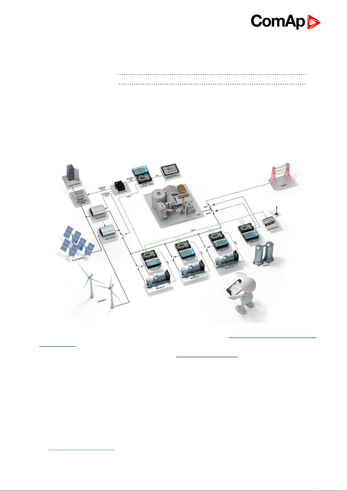
2.1 What is a Hybrid application?
Hybrid application combines conventional and non-conventional source for power generation. The most typical
application is with diesel gen-sets and photovoltaic plant as illustrated below.
Information about ComAp solution for hybrid applications can be found here: Hybrid power plant using ComAp’s
hybrid solution.
For complete description of hybrid applications see our Hybrid Application Guide.
2.1.1 How do ComAp controllers support Hybrid applications?
There are two different scenarios based on the position ComAp controllers are in – master or slave. This
document refers to and provides assistance with the set up of applications where ComAp InteliSys-NTC Hybrid
controller works as a master controller providing interface to gen-set controllers, as well as to renewable energy
source, and as such provides overall control of the hybrid application. Power management is provided by “slave”
InteliSys and InteliGen-set controllers with the IGS-NT-Hybrid firmware, which receives required value of
Dynamic Spinning Reserve from the InteliSys-NTC Hybrid.
Information about suitable genset controllers for hybrid applications and instructions for setup can be found in
the IGS-NT-Hybrid User guide.
InteliSys-NTC Hybrid 2.1.0 Global Guide
10
Page 11
2.1.2 How the InteliSys NTC Hybrid controller works?
The main duty of the IS-NTC-Hybrid is to collect information from the PV inverters (status, actual PV output,
statics, etc.), calculate accordingly the required DSR and share it with the other ComAp genset controllers over
CAN bus. The gen-set controllers are then responsible for optimum power management of the gen-sets with
respect to the renewable energy source, which output utilization must be maximized, and only in case the gen-
sets face the thread of being underloaded, the IS-NTC-Hybrid would curtail the output from the PV plant. The
limitation of the renewable energy source is based on a calculation considering the minimum allowed genset
loading level (Min GS Power setpoint) to prevent the gen-sets from underloading, resp. to protect the wind
turbine in high wind speeds.
2.2 Configurability and monitoring
One of the key features of the controller is the system’s high level of adaptability to the needs of each individual
application and wide possibilities for monitoring. This can be achieved by configuring and using the powerful
ComAp PC/mobile tools.
Supported configuration and monitoring tools:
GenConfig (page 11) – complete configuration and firmware upgrade
InteliMonitor (page 12) – multiple site monitoring and setpoint setting
WinScope (page 12)– special graphical monitoring software
WebSupervisor (page 12) – web-based system for monitoring and controlling
WebSupervisor mobile – supporting application for smartphones
Note: Use the GenConfig PC software to read, view and modify configuration from the controller or disk and
write the new configuration to the controller or disk.
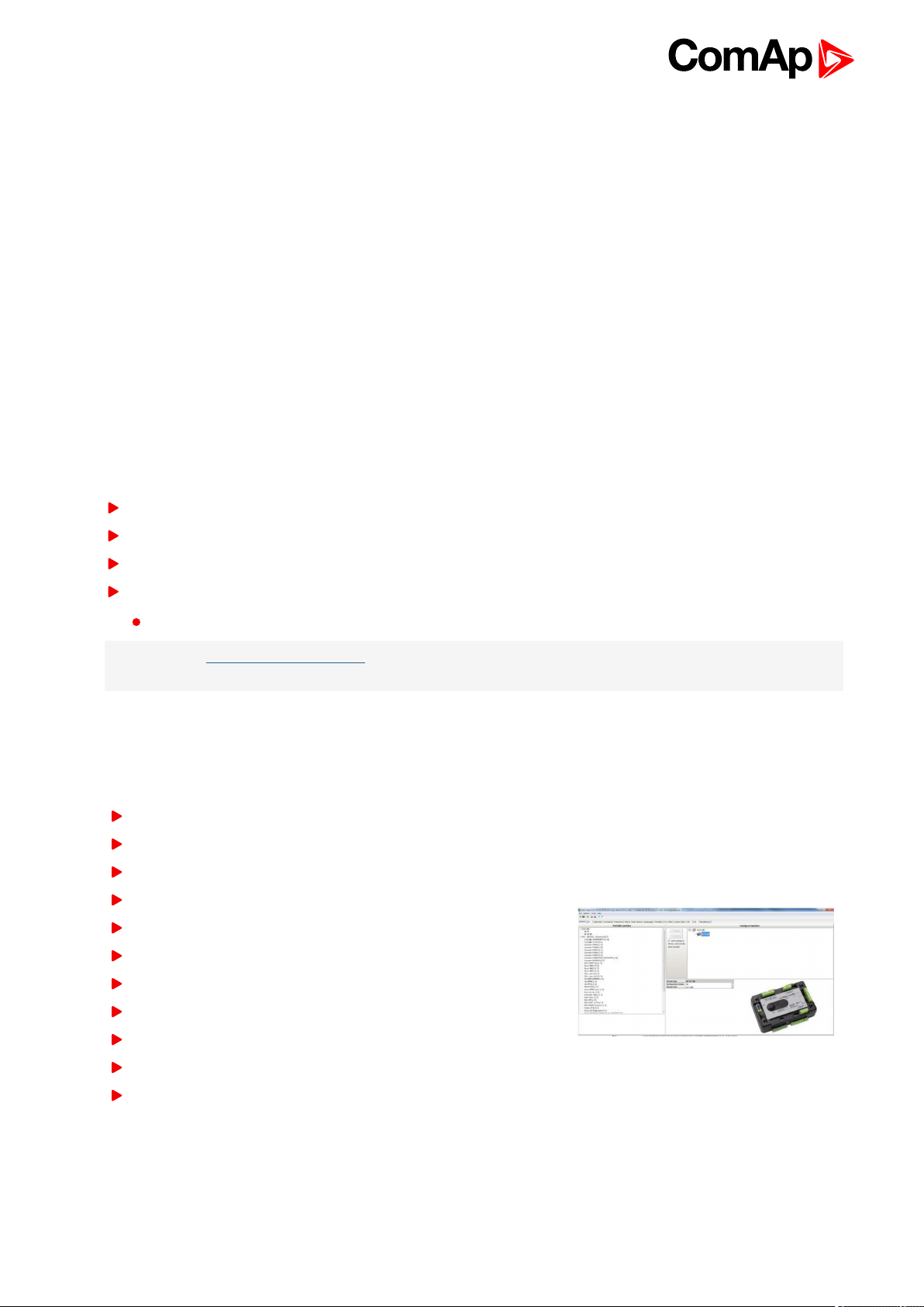
2.2.1 GenConfig
Configuration and monitoring tool for InteliSys-NTC Hybrid, InteliGenNT and other controllers.
Functions provided by GenConfig
Direct, modem or internet communication with the controller
Offline or online controller configuration
Controller firmware upgrade
Reading/writing/adjustment of setpoints
Binary/Analog Inputs and Outputs logical functions adjustments
Exporting data into a XLS file
Controller language translation
Screen Editor for editing InteliVision 5 a 8 screens
PLC Editor for editing built-in PLC functions
Updating and configuration of InteliVision 8 firmware
User Protections, User sensor curves, password protection and
history management
InteliSys-NTC Hybrid 2.1.0 Global Guide
11
Page 12
2.2.2 InteliMonitor
PC Monitoring tool for Inteli controllers.
Functions provided by InteliMonitor
Online monitoring of a controller or whole site
Fully customizable SCADA diagram
Reading/writing/adjustment of setpoints
Reading of measured values
Browsing of controller history records
2.2.3 WinScope
Special graphical controller monitoring software.
Functions provided by WinScope
Monitoring and archiving of ComAp controller’s parameters and
values
View of actual/historic trends in controller
On-line change of controllers’ parameters for easy regulator
setup
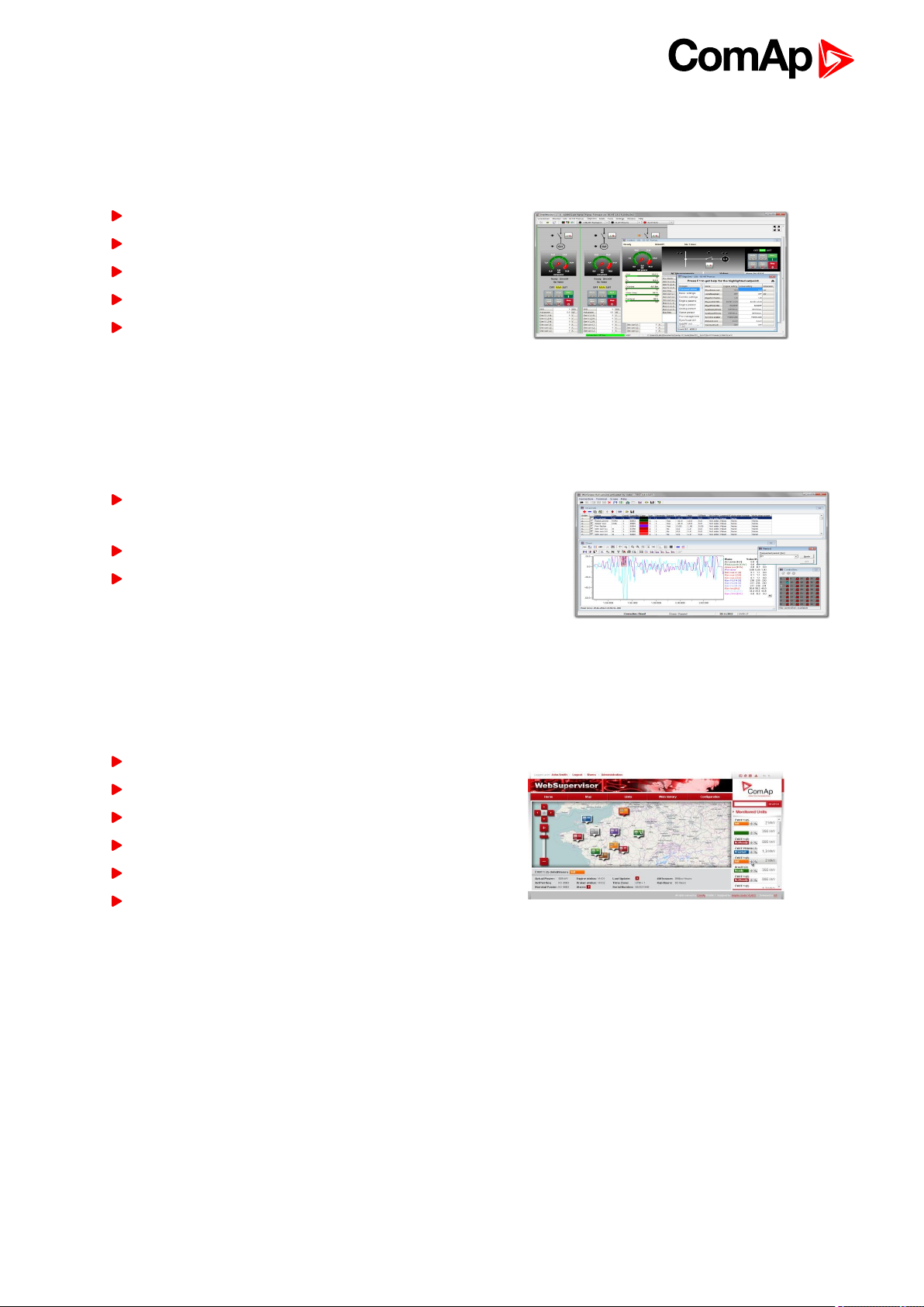
2.2.4 WebSupervisor
Web-based system for monitoring and controlling ComAp controllers.
Functions provided by WebSupervisor
Site and fleet monitoring
Reading of measured values
Browsing of controller history records
On-line notification of alarms
E-mail notification
Also available as a smartphone application
6 back to System overview
InteliSys-NTC Hybrid 2.1.0 Global Guide
12
Page 13
3 Installation and wiring
3.1 General 13
3.2 InteliSys NTC Hybrid Installation Instructions 16
3.3 Binary Input wiring 19
3.4 Binary Output wiring 20
3.5 Analog Input and Output wiring 21
3.6 CAN and RS485 bus wiring 23
6 back to Table of contents
There are currently three HW versions of InteliSys-NTC Hybrid controller. Please refer to the corresponding
portion of this chapter for installation instruction for your particular controller type. Chapters relevant for both
HW configurations are marked as “(general)”.
3.1 General
Controller type Hardware features
12 Binary Outputs
12 Binary Inputs
3.1.1 Wiring
To ensure proper function:
3 Analog Inputs
1 Analog Output
Mains and Bus Voltage measurement (3-phase)
Mains Current measurement (3-phase)
Auxiliary Current measurement (1-phase)
RS485 Communication port dedicated for display
RS485 Communication port for universal use with galvanic
separation
RS232 Communication port
CAN1 Communication port (for extension modules)
CAN2 Communication port (for intercontroller
communication and monitoring)
USB Communication port
RJ45 (Ethernet) Communication port
Use grounding terminals.
Wiring for binary inputs and analog inputs must not be run with power cables.
Analog and binary inputs should use shielded cables, especially when the length is more than 3 m.
InteliSys-NTC Hybrid 2.1.0 Global Guide
13
Page 14

Tightening torque, allowable wire size and type, for the Field-Wiring Terminals:
For Mains(Bus) Voltage, Generator Voltage a Current terminals
Specified tightening torque is 0.56Nm (5.0 In-lb)
Use only diameter 2.0-0.5mm (12-26AWG) conductor, rated for 90°C minimum.
For other controller field wiring terminals
Specified tightening torque 0.79Nm (7.0 In-lb)
Use only diameter 2.0-0.5mm (12-26AWG) conductor, rated for 75°C minimum.
Use copper conductors only.
3.1.2 Grounding
The shortest possible piece of wire should be used for controller grounding. Use cable min. 2.5 mm2. A brass
M4x10 screw with star washer securing ring type grounding terminal shall be used.
The negative “-” battery terminal must be properly grounded.
IMPORTANT: Switchboard and engine must be grounded at a common point. Use as short a cable
as possible to the grounding point.
3.1.3 Power supply
To ensure proper function:
Use power supply cable min. 2.5mm
Use fuse 2 amps
Maximal continuous DC power supply voltage is 36VDC.
IMPORTANT: Switchboard lightning strikes protection according standard regulation is expected!!!
The maximum allowable current through the controller negative terminal is 3 to 8A (depends on
the controller type and binary output load).
2
InteliSys-NTC Hybrid 2.1.0 Global Guide
14
Page 15
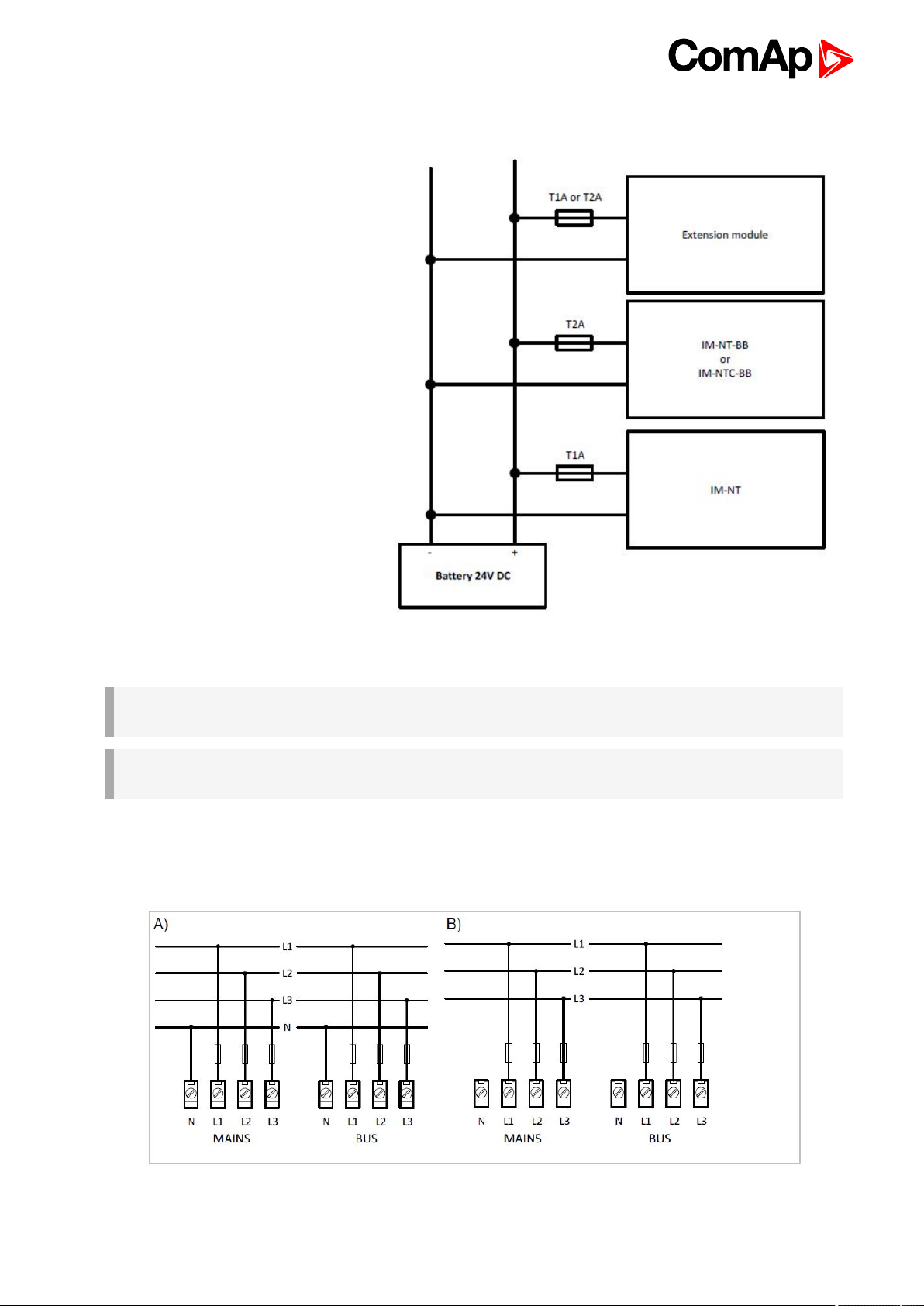
3.1.4 Power supply fusing
Always use according fuse (1Amp or
2Amps) when connection controller,
extension modules or relays to a power
source.
3.1.5 Voltage and current inputs
IMPORTANT: Risk of personal injury due to electric shock when manipulating voltage terminals
under voltage! Be sure the terminals are not under voltage before touching them.
IMPORTANT: Do not open the secondary circuit of current transformers when the primary circuit is
closed!!! Open the primary circuit first!
Use 1.5 mm2cables for voltage connection and 2.5 mm2for current transformers connection.
Adjust nominal voltage, nominal current, CT ratio and PT ratio by appropriate setpoints in the Basic Settings
group.
InteliSys-NTC Hybrid 2.1.0 Global Guide
Image 3.1 Voltage measurement wiring
15
Page 16

IMPORTANT: Check measurement connections carefully! Failure is possible if phases are
connected in wrong order (WrongPhSequence detected by the controller) but this is not detected if
the phases are just rotated (i.e. instead of phase sequence L1, L2, L3, phase sequence is e.g. L2,
L3, L1.
3.2 InteliSys NTC Hybrid Installation Instructions
This portion of Instalation instructions is dedicated to the InteliSys-NTC Hybrid-
BaseBox and InteliSys-NTC Hybrid-NTC-BaseBox controllers without built-in
display. If you have version with built-in display of the controller, please refer to
the section 3.1.
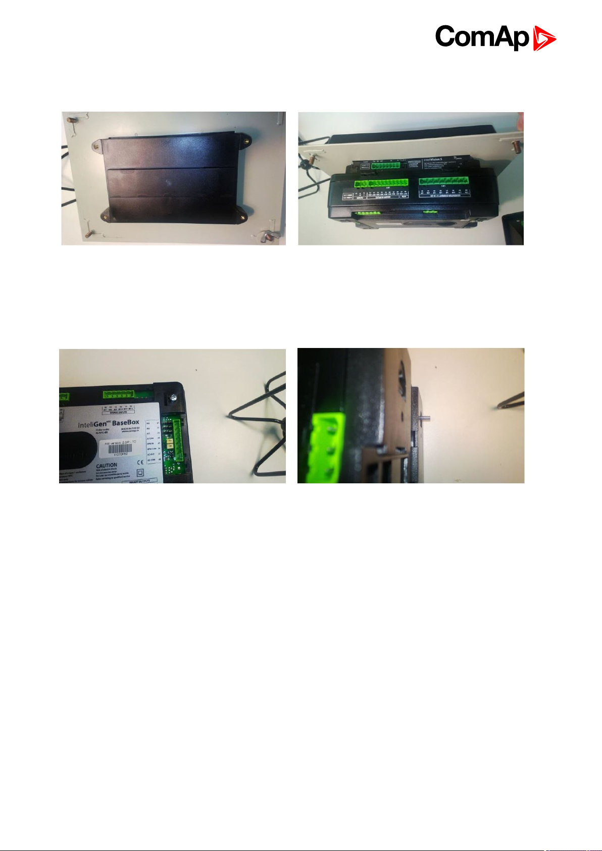
3.2.1 Mounting
BaseBox units are prepared for mounting on DIN rain mount (35mm).
Locate two plastic holders on the back side of the
controller
Mount the unit on the DIN rail and secure by pressing
two plastic holder until they click and fix the unit into
position
Make sure both holders are in open position (right
image). If not (left image) open them by pulling them
slightly out
InteliSys-NTC Hybrid 2.1.0 Global Guide
16
Page 17
BaseBox units may also be mounted on InteliVision 5 and together with it mounted into cut-out in a
switchboard.
Use the rail provided on the back side of InteliVision 5 and
Mount InteliVision 5 into the switchboard cut-out (for
more information on InteliVision 5 mounting please
refer to the InteliVision 5 Reference Guide)
mount the controller to it while following the same steps
when mounting on standard rail (rail openings on
InteliVision 5 are fixed so there is only one possible way
how to mount the controller to it)
Locate four screw holes on the front of the controller
Insert provided screws and use them to secure the
controller mounted to InteliVision 5 (screws fit into
InteliVision 5 holder pieces)
InteliSys-NTC Hybrid 2.1.0 Global Guide
17
Page 18
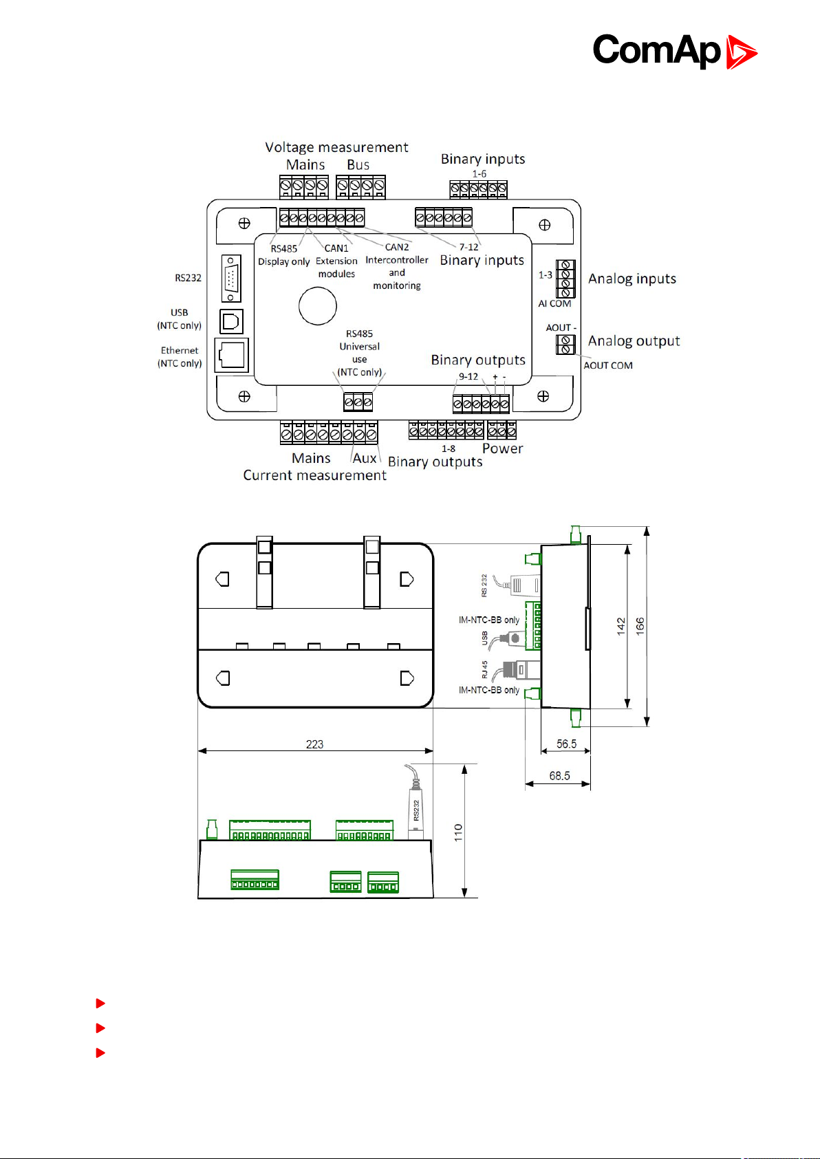
3.2.2 Terminal diagram, Dimensions
3.2.3 Package contents
The package contains:
Controller
Mounting holders
Terminal blocks
InteliSys-NTC Hybrid 2.1.0 Global Guide
18
Page 19
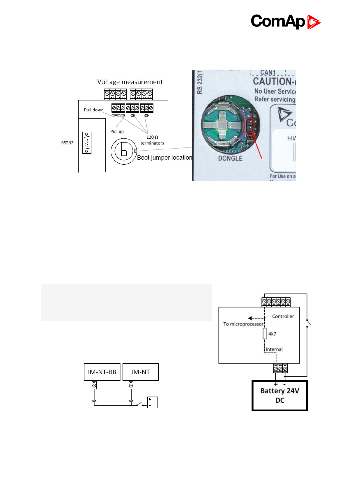
3.2.4 Jumper settings
There are several jumpers available on the unit. Their location and purpose is described below:
Use boot jumper if controller is not responding to communication (e.g. due to faulty programming sequence).
Take off the rubber cover using screwdriver to acces boot jumper next to dongle slot.
Use 120 Ω terminators at the end of CAN1, CAN2 or RS485 buses. Do not use these terminators on units that
are not terminating the bus.
Use pull up and pull down resitors on RS485 to bias the line when no device is active on the bus to prevent noise
from undriven line to be interpreted as data.
3.3 Binary Input wiring
Use min. 1 mm2cables for wiring of binary inputs.
Note: The name and function or alarm type for each binary input
have to be assigned during the configuration. Binary inputs may be
used in built-in PLC as well. Please refer to the manual of GenConfig
for more information.
It is recommended to use separation diodes when multiple binary input
terminals are connected together to prevent unwanted activation of
binary input when one of the controllers is switched off.
InteliSys-NTC Hybrid 2.1.0 Global Guide
19
Page 20
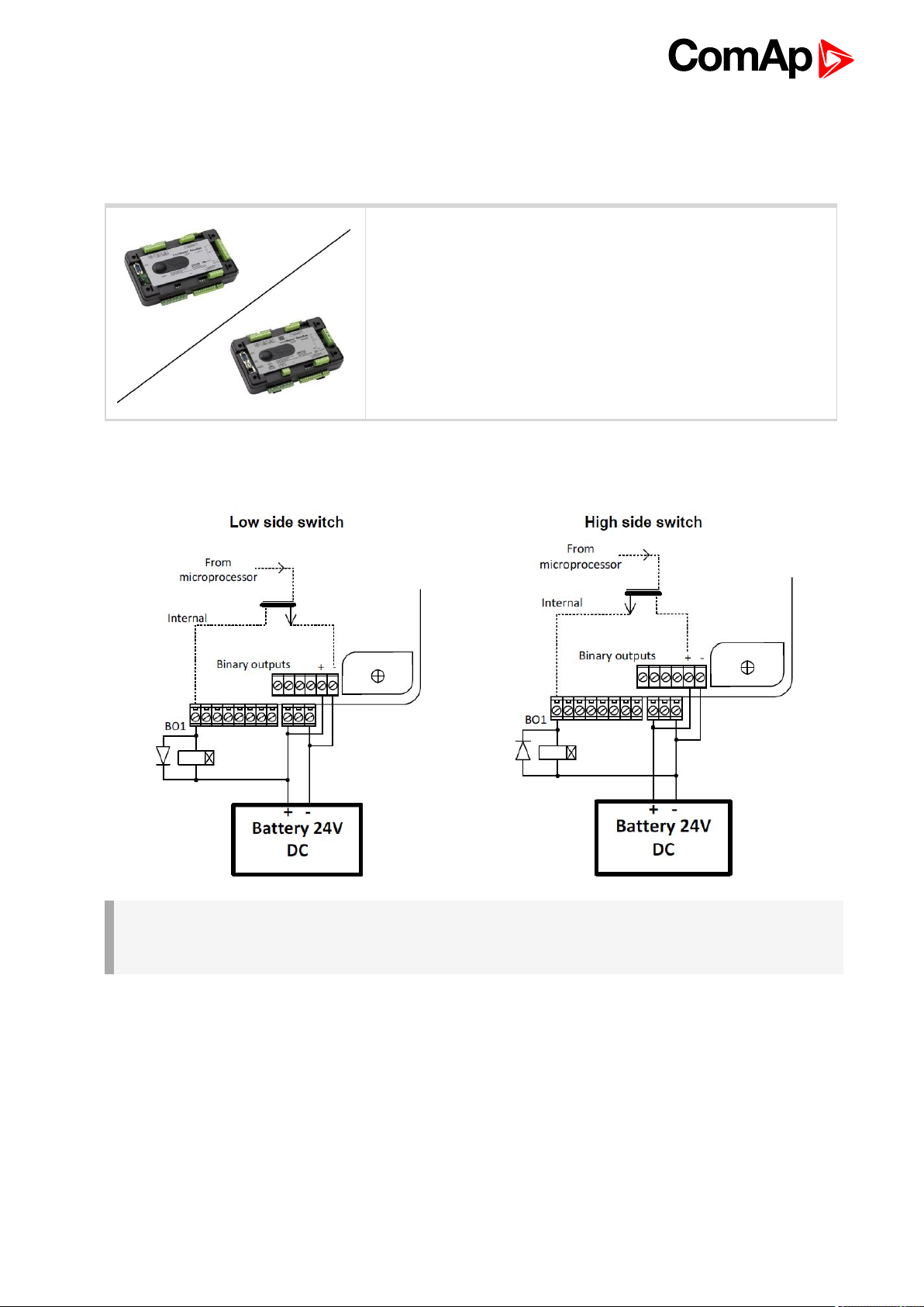
3.4 Binary Output wiring
3.4.1 IM-NT-BB and IM-NTC-BB
This portion of Installation instructions is dedicated to the InteliSys-
NTC Hybrid-BaseBox and InteliSys-NTC Hybrid-BaseBox
controllers without built-in display. If you have version with built-in
display of the controller, please refer to the section 3.8.1.
It is possible to use binary outputs as low side switch or high side switch in BaseBox type of controller. For
correct wiring in both cases please refer to the following diagrams.
IMPORTANT: Both power supply sockets for binary outputs need to be connected to ensure proper
function of binary outputs.
Never use DC relays without protection diodes!
InteliSys-NTC Hybrid 2.1.0 Global Guide
20
Page 21
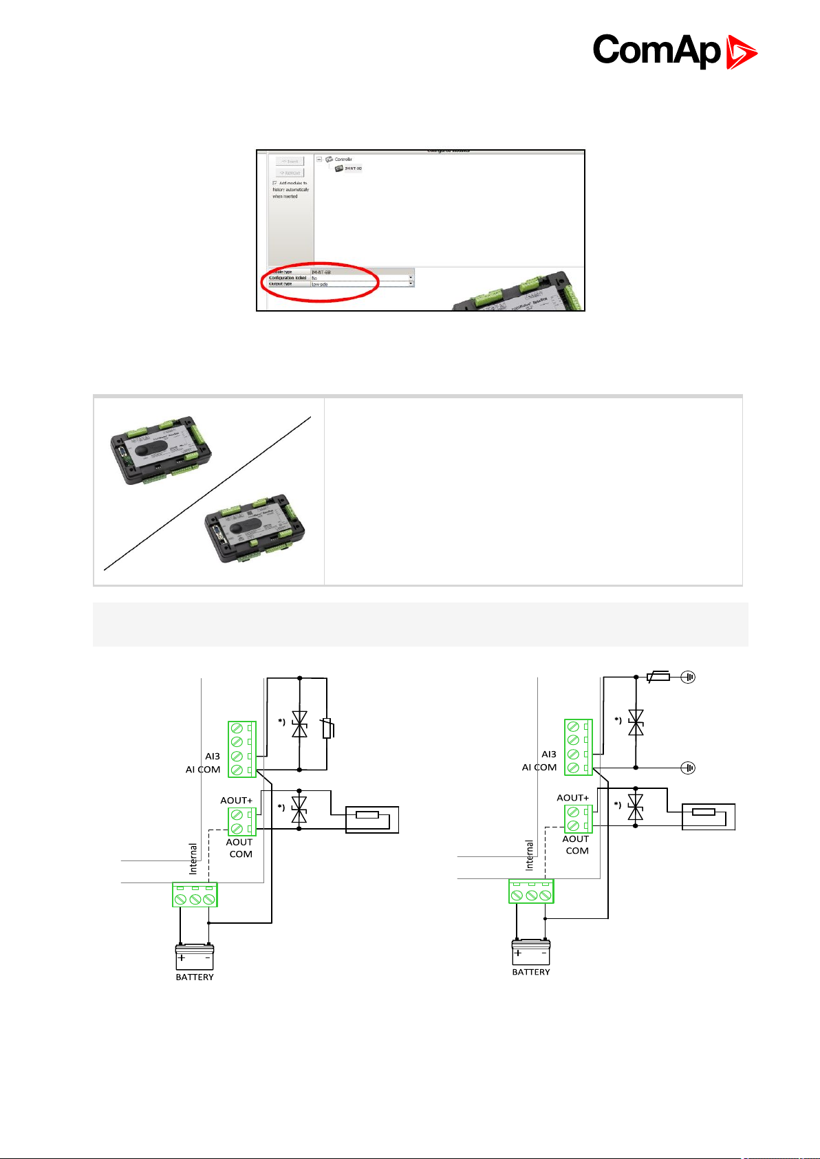
Low side or High side function of binary outputs can be chosen in configuration tool GenConfig in Modules tab.
This configuration is used for all binary inputs available on the controller.
3.5 Analog Input and Output wiring
This portion of Installation instructions is dedicated to the InteliSys-
NTC Hybrid-BaseBox and InteliSys-NTC Hybrid-BaseBox
controllers without built-in display. Analog inputs and output are not
available in InteliSys-NTC Hybrid-GC.
Note: For more information on technical data regarding supply, inputs, outputs etc. please refer to For jumper
setting of Analog inputs please refer to the section 3.2.4 Jumper settings.
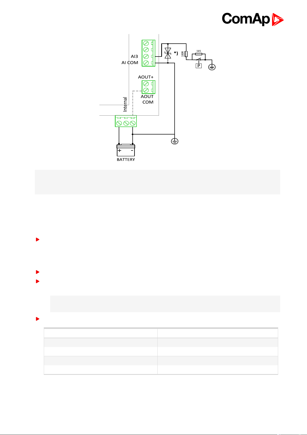
Resistive sensor with grounding on Analog input 3
Resistive sensor on Analog input 3 and Analog output wiring
and Analog output wiring. Note, that battery
should be also grounded to common ground in all
cases!
InteliSys-NTC Hybrid 2.1.0 Global Guide
21
Page 22
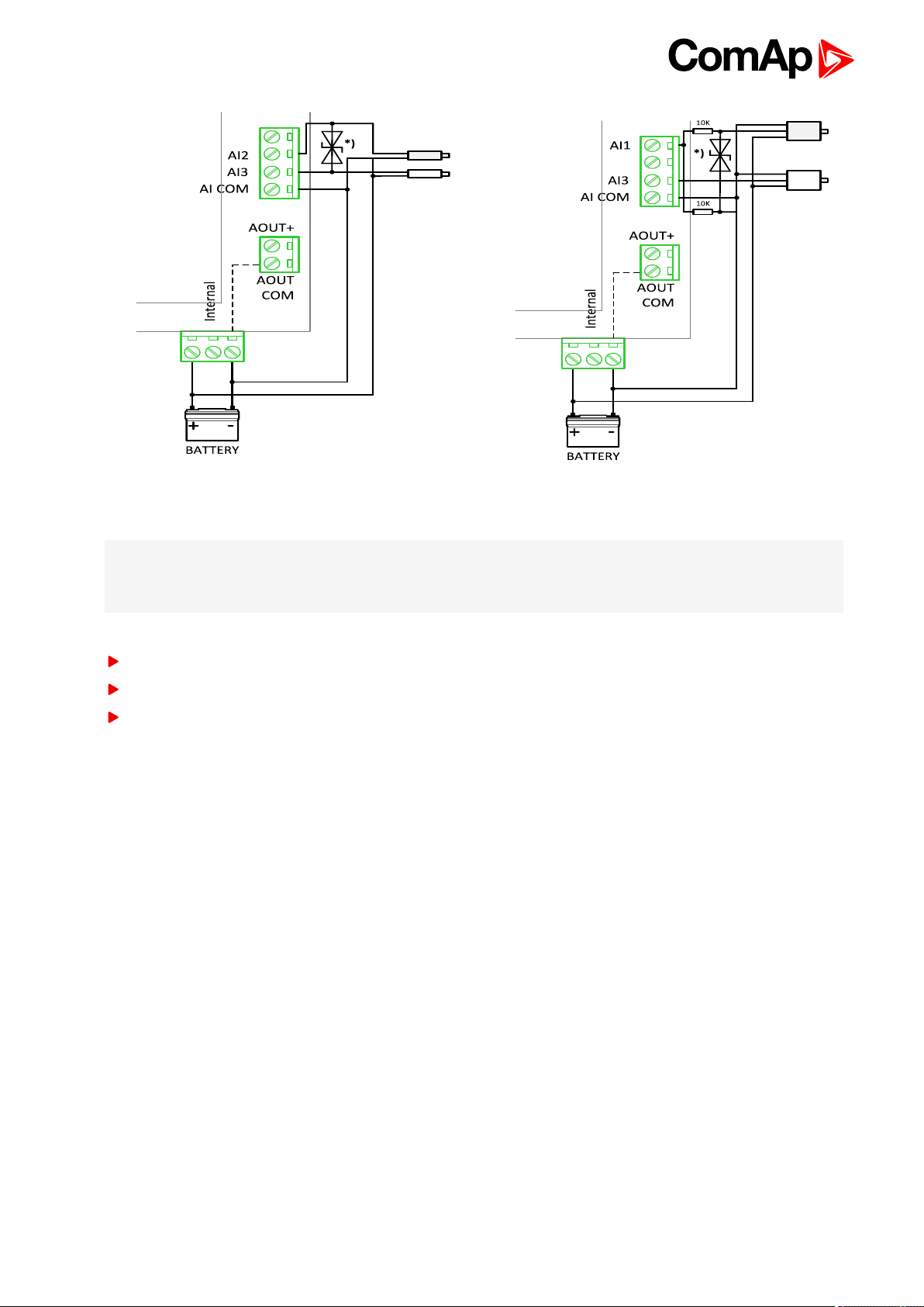
Passive Current sensor on Analog input 3 and Active Current
sensor on Analog input 2
Note: *)
Transient Voltage Suppressor Diode parameters: 12 V, 600 W, through hole TVS diode type, bidirectional.
Transient Voltage Suppressor Diode is used only when the installation is to be according to IEC 60255-1.
Tristate sensor (binary sensor with fail detection) on Analog input 3
Below 750Ω = Inactive
Between 750Ω and 2400Ω = Active
Below 10Ω or Over 2400Ω = sensor failure (wire shorted or interrupted)
Voltage sensors on Analog input 1 and 3
InteliSys-NTC Hybrid 2.1.0 Global Guide
22
Page 23
Note: *)
Transient Voltage Suppressor Diode parameters: 12 V, 600 W, through hole TVS diode type, bidirectional.
Transient Voltage Suppressor Diode is used only when the installation is to be according to IEC 60255-1.
3.6 CAN and RS485 bus wiring
The wiring of the CAN bus communication should be provided in such a way that the following rules
are observed:
The maximum length of the CAN bus depends on the communication speed. For a speed of 250 kbps, which
is used on the CAN1 bus (extension modules, ECU) and CAN2 bus if it is switched to 32C mode, the
maximum length is 200 m. If the CAN2 bus is switched to 8C mode the speed is 50 kbps and the maximum
length is 800 m.
The maximum length of the RS485 bus is 1000 m
The bus (CAN and RS485) must be wired in linear form with termination resistors at both ends. No nodes are
allowed except on the controller terminals.
Note: A termination resistors at the CAN and RS485 are already implemented on the PCB. For
connecting, close the jumper near the appropriate CAN or RS485 terminal.
Use a cable with following parameters:
Cable type Shielded twisted pair
Impedance 120 Ω
Propagation velocity ≥75% (delay ≤4.4 ns/m)
Wire crosscut ≥0.25 mm
Attenuation (@1MHz) ≤2dB / 100 m
InteliSys-NTC Hybrid 2.1.0 Global Guide
2
23
Page 24
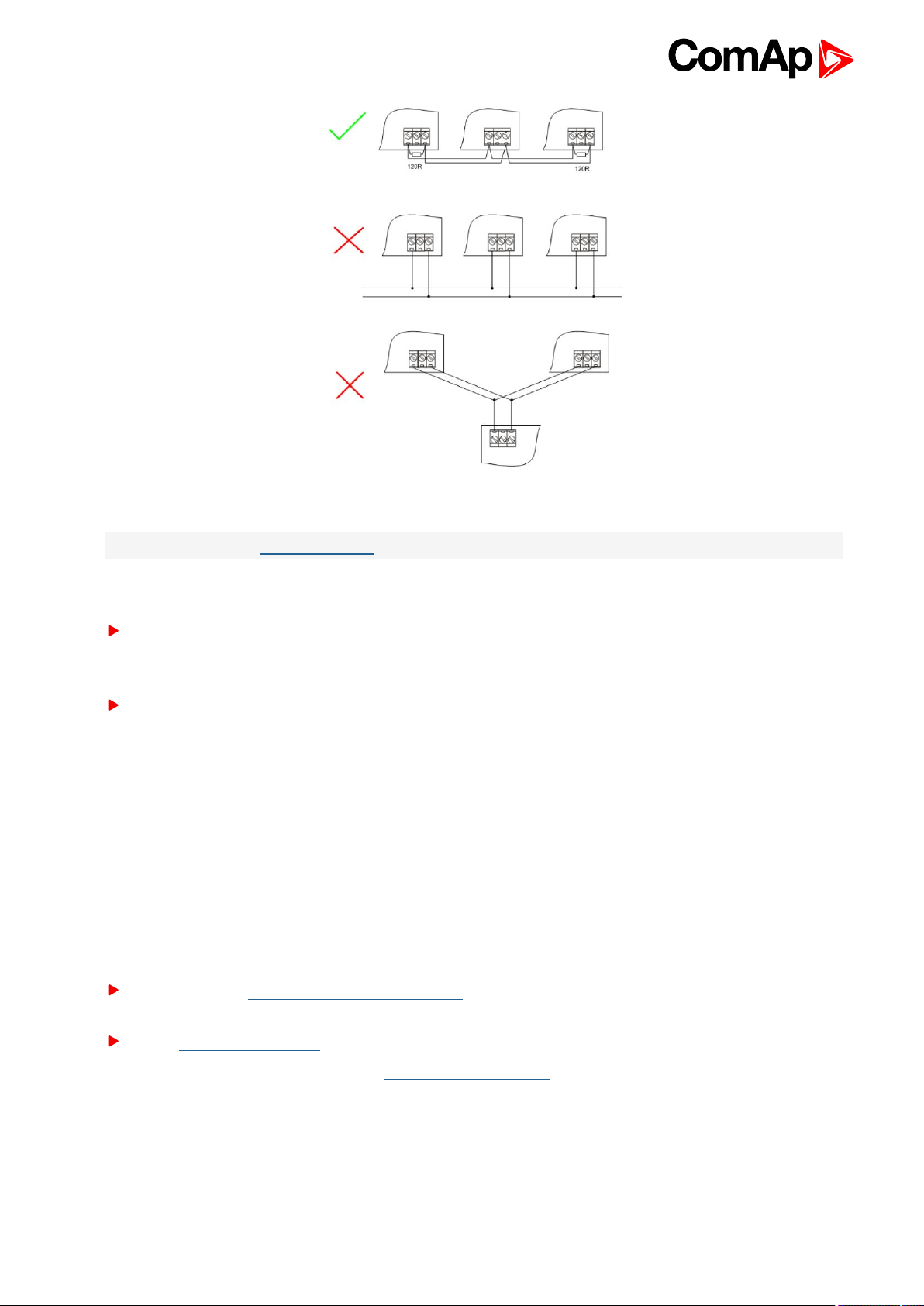
Image 3.2 CAN and RS485 BUS topology
Note: See the website www.can-cia.org for information about the CAN bus, specifications, etc.
According to the certification of the non-galvanical isolated RS485 (marked RS485 (1), Display) due to the IEC
60255-1 have in mind following:
It's possible connect directly to the controller maximally 3 devices by shielded communication cable with
maximum bus length 150m using bi-directional transils 68V 600W on each signal (A, COM, B) against
ground.
If the condition above is not fulfilled, it is necesary to use external separator with galvanic isolation minimally
2000V, surge resistant (e.g. CommFront RS485 / RS422 ISOLATOR / REPEATER / CONVERTER –
INDUSTRIAL, designation type RPT-485_422-4)
3.6.1 Wiring examples
1. For shorter distances (all network components within one room) – picture 1 interconnect A and B; shielding
connect to PE on controller side
2. For longer distances (connection between rooms within one building) – picture 2 interconnect A, B, COM;
shielding connect to PE at one point
3. In case of surge hazard (connection out of building in case of storm etc.) – picture 3
We recommend using the following protections:
Phoenix Contact (http://www.phoenixcontact.com): PT 5-HF-5DC-ST with PT2x2-BE (base element)(or
MT-RS485-TTL)
Saltek (http://www.saltek.eu): DM-006/2 R DJ
Recommended data cables: BELDEN (http://www.belden.com)
1. For shorter distances: 3105A Paired – EIA Industrial RS485 PLTC/CM (1x2 conductors)
2. For shorter distances: 3105A Paired – EIA Industrial RS485 PLTC/CM (1x2 conductors)
3. In case of surge hazard: 3106A Paired – EIA Industrial RS485 PLTC/CM (1x2+1 conductors)
InteliSys-NTC Hybrid 2.1.0 Global Guide
24
Page 25
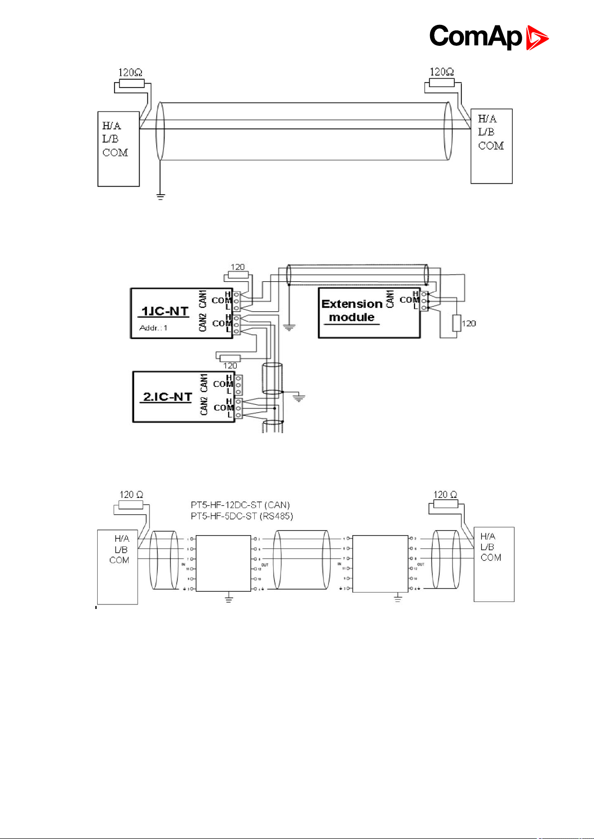
Image 3.3 Shorter distances (all network components within one room)
Image 3.4 Longer distances (connection between rooms within one building)
Image 3.5 Surge hazard (connection out of building in case of storm etc.)
6 back to Installation and wiring
InteliSys-NTC Hybrid 2.1.0 Global Guide
25
Page 26

4 Controller setup
4.1 Connection to a controller usingPC 26
4.2 Modification of configuration, setpoints etc 30
4.3 Programming of a controller 31
4.4 Changing the language 34
4.5 Password management 35
4.6 Related tools 37
4.7 Functions 39
4.8 Renewables Interface 139
4.9 Protections and Alarm management 142
4.10 MGCB/MCB fail detection 149
4.11 Controller operation states 156
6 back to Table of contents
In this section brief introduction is presented how to
Connect to a controller,
Modify various settings,
Program controller and reprogram non-responsive controller,
Manage passwords and password protections and
Operate related tools (ScreenEditor, PLC Editor etc.).
is presented.
4.1 Connection to a controller usingPC
There are several available ways to connect to controller using PC for monitoring, control or
configuration/programming. For more information on related PC tools see Configurability and monitoring on
page 11.
4.1.1 Direct connection
A direct connection can be realized by RS232 connection or USB connection (available on NTC BaseBox only).
Figures below illustrate the connection setting in GenConfig and InteliMonitor.
Note: RS232 can be used only for configuration, not operation communication when installation is to be
according to IEC 60255-1
InteliSys-NTC Hybrid 2.1.0 Global Guide
26
Page 27
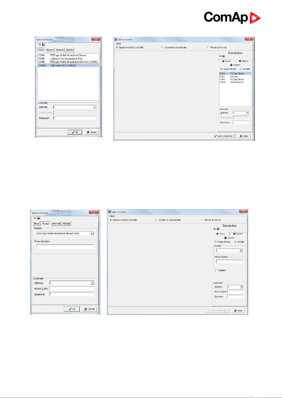
Image 4.1 GenConfig
Select according COM port, adjust CAN address and enter password (optional for locked configuration).
Image 4.2 InteliMonitor
4.1.2 Modem connection
A modem connection can be realized by suitable modem connected to the controller. Figures below illustrate the
connection setting in GenConfig and InteliMonitor.
Image 4.3 GenConfig Image 4.4 InteliMonitor
Select connected modem, adjust Phone number and enter CAN address and enter correct Access Code for
remote connection. Enter password (optional for locked configuration).
It is possible to adjust number of rings before the controller accepts the connection from modem – use Comms
settings:NumberRings AA.
InteliSys-NTC Hybrid 2.1.0 Global Guide
27
Page 28

4.1.3 Internet connection
Internet (Ethernet) connection can be used directly in NTC BaseBox version of the controller. For connection to
other versions, use InteliBridge-NT device. Figures below illustrate the connection setting in GenConfig and
InteliMonitor.
Image 4.5 GenConfig Image 4.6 InteliMonitor
Adjust IP address of the controller (InteliBridge-NT) you want to connect to. Select CAN address of the
controller. Enter Access Code for remote connection. Enter password (optional for locked configuration).
Note: The controller must have public IP address or it must be reachable for connection in the specific network.
InteliSys-NTC Hybrid 2.1.0 Global Guide
28
Page 29
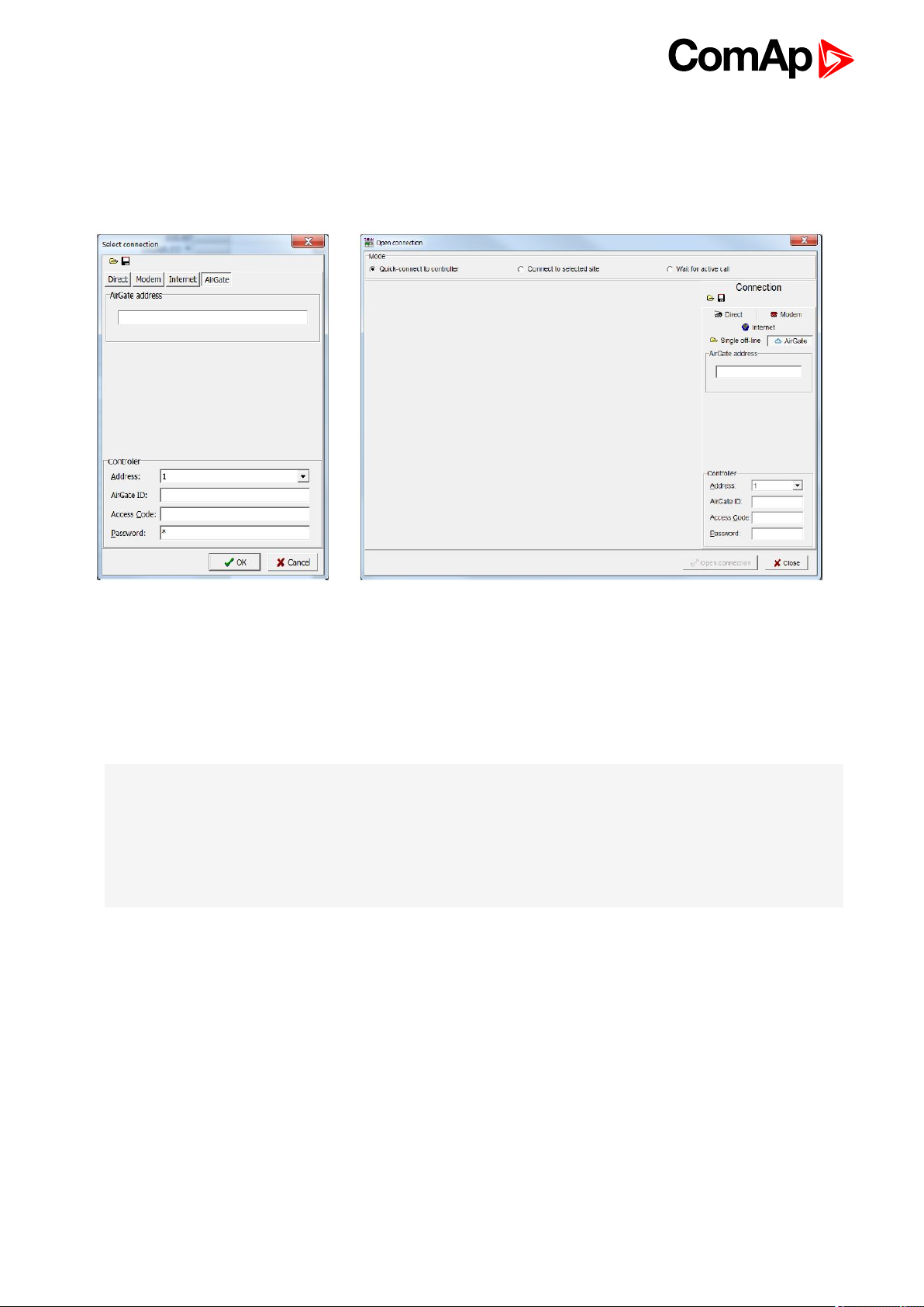
4.1.4 Airgate connection
AirGate connection can be used directly in NTC BaseBox version of the controller. For connection to other
versions, use InternetBridge-NT device. Figures below illustrate the connection setting in GenConfig and
InteliMonitor.
Image 4.7 GenConfig Image 4.8 InteliMonitor
Enter AirGate address of a server with AirGate service (currently airgate.comap.cz). Select CAN address of the
controller you want to connect to. Enter AirGate ID of the controller (InteliBridge-NT) you want to connect to
(AirGate ID is assigned automatically if the controller is properly connected to the Internet and corresponding
AirGate setting is enabled. You can find AirGate ID in controller values.). Enter Access Code for remote
connection. Enter password (optional for locked configuration).
Note: What is AirGate service? AirGate is a service provided for free by ComAp which allows users to connect
to controllers even though they are not assigned public IP address or if there are behind corporate firewalls.
Controller connects to the AirGate server (secure and fast server located in Central Europe) and obtains
AirGate ID (used in the connection, see above). Then it communicates with the server on a secure line and any
user that know AirGate ID and access code for that particular controller can connect from anywhere (Internet
access needed) to the controller and monitor and control it.
4.1.5 Connection to multiple controllers
Connection to multiple controller is available in InteliMonitor. It is possible to connect to multiple controller using
Direct connection to I-LB+, using Internet connection to NTC BaseBox controllers or to InteliBridge-NT, using
modem connection capable of multiple connections or AirGate connection to multiple NTC BaseBox controllers
or to InteliBridge-NT.
InteliSys-NTC Hybrid 2.1.0 Global Guide
29
Page 30

Image 4.9 Direct multiple connection
Image 4.10 Internet multiple connection (use InternetBridge-NT IPs for connection to NTC
BaseBox controllers as well)
Image 4.11 AirGate multiple connection (fill in AirGate IDs for each controller, when using
InteliBridge-NT fill in InteliBridge-NT AirGate ID for each controller)
4.2 Modification of configuration, setpoints etc
For full configuration of controller configuration use GenConfig. You may open archive prepared for specific
application and upload it to the controller. You may also change:
Controller type (Modules tab)
Extension modules (Modules tab)
Binary Input and Output logical functions and protections (I/O tab)
Analog input sensor type, logical functions and protections (I/O tab)
Analog output function, conversion, normalization, resolution (I/O tab)
Setpoints and password level for particular setpoint (Setpoints tab)
Commands password protection (Commands tab)
InteliSys-NTC Hybrid 2.1.0 Global Guide
30
Page 31

Prepare custom protections (Protections tab)
Modify History data selection (History tab)
Prepare custom user sensor characteristics (User Sensor tab)
Modify languages settings (Languages tab)
Translate corresponding names to other language prepared in Languages tab (Translator tab)
Prepare complex logical functions with built-in PLC functions (PLC Editor tab)
Modify screens for InteliVision 5 and 8 (ScreenEditor tab)
Review and modify assigned logical binary functions (LBI tab)
Review and modify assigned logical analog functions (LAI tab)
Select power format, rename Pulse counters and Remote switches (Miscellaneous tab)
IMPORTANT: Do not forget that changes in GenConfig are not sent to the controller unless you
write them to the controller.
In InteliMonitor it is possible to configure:
Setpoints (multiple setpoint configuration in several controllers at once)
Set/Reset statistics
Administrate users and their rights
IMPORTANT: Do not forget that all changes in InteliMonitor are sent to the connected controller
and controller immediately acts on it. Do not change CAN address of the controller or connection
is lost and need to be re-established with new CAN address.
4.3 Programming of a controller
4.3.1 Standard programming
For programming GenConfig is used. Select correct connection mode and then select the following option:
InteliSys-NTC Hybrid 2.1.0 Global Guide
31
Page 32

You may use “FW upgrade (from default configuration)” (this will overwrite all of the settings in the controller with
default settings. If you need to upgrade firmware from existing configuration, select “FW upgrade (from existing
configuration)”. This function will automatically open wizard which will help you update the existing configuration
to be compatible with the newly selected firmware.
4.3.2 Programming of non-responsive controller
If the controller does not contain valid firmware, new firmware cannot be programmed in the standard way. This
situation can occur if the connection between the PC and the controller was interrupted e.g. during a previous
firmware upgrade. In such case the controller may have a blank display or connection to InteliVision may not be
established and it does not communicate with the PC. The bootjumper must be used to get valid firmware into
the controller.
Connect proper cable for programming (use RS232 port).
Open GenConfig and select “FW upgrade (default configuration)”
From the following table select FW that is required or click open and browse your files to find firmware in
non-default location
InteliSys-NTC Hybrid 2.1.0 Global Guide
32
Page 33
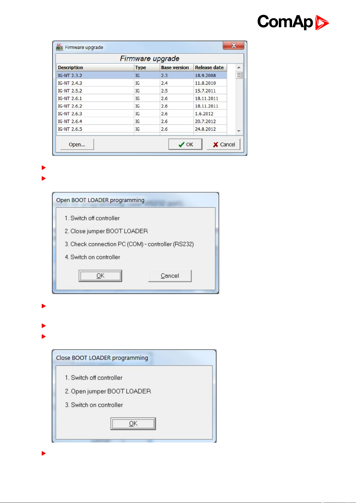
Click OK
Wait until the connection times out and following dialog appears
Follow the instructions and then click OK (information regarding the location of boot jumper can be found in
section 3.1.4 (IM-NT GC) or 3.2.4 (IS-NTC HYBRID and IS-NTC HYBRID)
Programming starts momentarily
When the programming is done following dialog appears
Follow the instructions and press OK. Following diagram will appear and programming is done
InteliSys-NTC Hybrid 2.1.0 Global Guide
33
Page 34
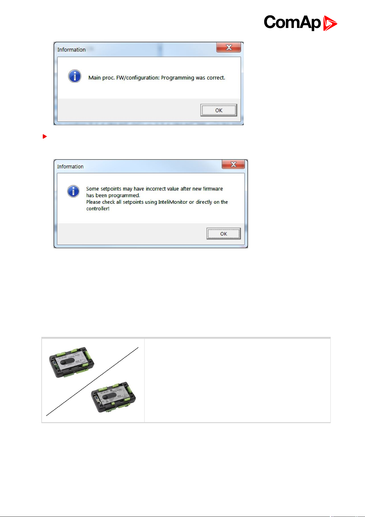
Additional dialog warns you that the setpoints may have improper values. Change the configuration in
normal way.
4.4 Changing the language
There is step-by-step guide in GenConfig help available for the Languages and Translator tabs which contains
all the information on how to prepare new languages in the configuration (press F1 in Languages or Translator
tab or go to Help->GenConfig Help and locate corresponding chapters).
4.4.1 Selection of the language in InteliSys
This portion of instructions is dedicated to the InteliSys-NTC Hybrid
controller without built-in display. If you have version with built-in
display of the controller, please refer to the section 4.4.2.
NTC
Hybrid
InteliSys-NTC Hybrid 2.1.0 Global Guide
34
Page 35

If using BaseBox version of the controller you may use InteliVision 5, InteliVision 8 or InteliVision 17 Touch. If
you need to use for some reason IG or IS-Display please refer to the chapter 4.4.1 for the instructions regarding
built-in display which works the same as the external displays.
For InteliVision 5 an 8 go to main menu and select Help/Others and Languages. Scroll up and down and select
preferred langugue. Confirm by pressing enter.
If you are using InteliVision 17, it is running standard InteliMonitor software. Please refer to the manual of
InteliMonitor how to change fonts in InteliMonitor and in custom SCADA.
Note: you need to use graphical language you may need to upload correct set of characters into the InteliVision
via controller. By default Chinese character set is uploaded in the controller. If you need to use for example
Korean characters (Hangul), in GenConfig select following menu while connected to the controller: File ->
Firmware upgrade and Cloning -> Display GC font change / FW upgrade. GenConfig connects to the controller
and new fonts may be uploaded to the controller as well as new firmware for the built-in display.
4.5 Password management
Password management requires InteliMonitor for user names, passwords and rights modification. It also
requires GenConfig for assigning corresponding setpoints and command to correct right groups.
4.5.1 User administration
User administration is available only when logged in as an Administrator. Once logged in select “Admin users…”
as shown on the right.
Following dialog is displayed:
Enable or disable users. Change user names and by double clicking change the access groups that are
accessible by particular user. Hold CTRL and click separate access groups to select only several of them with
no access to lower groups.
Log in as a different user to change password for that particular user.
Note: Newly enabled user has always default password “0”.
InteliSys-NTC Hybrid 2.1.0 Global Guide
35
Page 36

4.5.2 Access group setting in GenConfig
To assign particular setpoint to access group use the following function in GenConfig (by clicking select the
correct access group).
Note: Each setpoint may be assigned to only one access group. This setpoint can be changed by all users with
activated corresponding access rights.
To assign particular command to access group use the following function in GenConfig (by clicking select the
correct access group).
Note: Each command may be assigned to only one access group. This command can be used by all users with
activated corresponding access rights.
InteliSys-NTC Hybrid 2.1.0 Global Guide
36
Page 37

4.5.3 Password break protection
Password break protection (PBP) can be adjusted to ENABLED or DISABLED by a tick box in password
management in InteliMonitor (see the figure below). Default value is ENABLED.
Warning “PassInsertBlck” is displayed in alarm list during the blocking period.
Controller does not accept attempts to insert correct or incorrect password during the blocking period. In
case of this attempt there is a message displayed in InteliMonitor, GenConfig and InteliVision 5 and 8 which
states the remaining time of blocking.
Controller is blocked for 5 minutes if there were 6 attempts to insert incorrect password. In case of another six
failed attempts (after the period of blocking elapses) the blocking period is 30, 60, 120 and 240 minutes long
respectively.
History record “Incorrect password” is written after the 6th failed attempt to enter password (i.e. this record is
written once the PBP is activated). During the blocking no history records of inserting incorrect or correct
password are written.
Entering of passwords during the blocking period does not prolong the blocking period (passwords are not
actually entered because they are rejected by the controller at all).
When the controller is switched OFF and ON again (i.e. power down and up again) during the blocking period,
the blocking period is reset back to the full length of currently active PBP (e.g. if there is 24 minutes remaining
out of 30 minutes after the controller reset there will be again 30 minutes remaining).
After the correct password is inserted the PBP blocking period for next 6 failed attempts is reverted back to 5
minutes.
4.6 Related tools
There are two tools available for user regarding the configuration of the controller:
ScreenEditor – it can be used to modify screens in InteliVision 5 and 8
InteliSys-NTC Hybrid 2.1.0 Global Guide
37
Page 38

PLC Editor – it can be used to create and modify built-in PLC functions
Note: For more information on ScreenEditor use help in GenConfig (Help -> ScreenEditor Help).
For more information on PLC Editor use GenConfig Reference Guide.
InteliSys-NTC Hybrid 2.1.0 Global Guide
38
Page 39

4.7 Functions
4.7.1 Overview 40
4.7.2 Modes 54
4.7.3 Process Limitation 58
4.7.4 System start 64
4.7.5 StartUpSynchronization 65
4.7.6 Power management 65
4.7.7 Dynamic Spinning Reserves 97
4.7.8 Remote Alarm Messaging 97
4.7.9 Controller Redundancy 99
4.7.10 System load control modes 100
4.7.11 Managing system load control modes 103
4.7.12 Renewables Active Power Control 108
4.7.13 Renewables Reactive Power Control 111
4.7.14 Multiple Mains Feeders Support 113
4.7.15 System PF control modes 115
4.7.16 Automatic Mains Failure function 117
4.7.17 Regulation loops 119
4.7.18 Force value – step by step guide 121
4.7.19 Values for continuous writing from external sources 123
4.7.20 General Purpose Timers 124
4.7.21 History Related functions 125
4.7.22 User Buttons 127
4.7.23 Remote Control Function 128
4.7.24 Virtual Peripheral Inputs-Outputs (VPIO) module 129
4.7.25 Shared Inputs and Outputs 129
4.7.26 Distributed Binary Inputs and Outputs 131
4.7.27 MODBUS 132
4.7.28 Analog Input Sensors and User Sensors 134
4.7.29 Languages and Translator tool in GenConfig 134
4.7.30 System Start/Stop 135
4.7.31 Power Formats 135
4.7.32 Soft Unload with support of IAux measurement 136
4.7.33 System Isolated 138
4.7.34 User Mask function 138
4.7.35 Switchable Current measurement ratio 139
4.7.36 PLC functions 139
6 back to Table of contents
InteliSys-NTC Hybrid 2.1.0 Global Guide
39
Page 40

4.7.1 Overview
Note: There are numerous built-in functions in the controller that can be modified or combined to produce new
functions for specific uses. Note that it is not possible to describe all the combinations or modifications in detail
in this manual. Users are encouraged to find new way of how to use existing functions to their benefit.
Function Name Brief Description Related Setpoints, Inputs and Outputs
There are vast options regarding
access restrictions in the
controller. It is possible to lock:
Access locking
from various
sources
Active call,
emailing and SMS
service
Buttons for various
commands on the terminal.
External buttons for various
commands on binary inputs.
Built-in terminal or terminal
#1 to monitoring mode only.
External local terminal or
terminal #2 to monitoring
mode only.
All external remote
terminals (PC connection,
displays on all buses except
on RS485 dedicated port).
This function allows user to choose
under which conditions active
emailing happens, what is the type
of the message and separate
addresses or numbers. Learn more
about these functions in a separate
chapter.
Local buttons
ACCESSLOCK INT
ACCESSLOCKD#2
ACCESSLOCK D#3
ACCESSLOCK EXT
FAULTRESBUTTON
HORNRESBUTTON
STOPBUTTON
History record
Alarm only
Warning
Mains protect
MainsP w/Reset
AcallCH1-Type
AcallCH2-Type
AcallCH3-Type
AcallCH4-Type
AcallCH5-Type
AcallCH1-Addr
STARTBUTTON
MCBBUTTON
MGCBBUTTON
ActCallAttempt
Acall+SMS lang
ISSUEACTCALLC1
ISSUEACTCALLC2
ISSUEACTCALLC3
ISSUEACTCALLC4
ISSUEACTCALLC5
SMTP authent
SMTP user name
SMTP password
Alternative
brightness for
built-in InteliGen
display
InteliSys-NTC Hybrid 2.1.0 Global Guide
It is possible to choose two
different levels of brightness and
switch them with logical binary
input.
AcallCH2-Addr
AcallCH3-Addr
AcallCH4-Addr
AcallCH5-Addr
Alt brightness
SMTP address
Contr mailbox
Time zone
40
Page 41

Function Name Brief Description Related Setpoints, Inputs and Outputs
It is possible to leave the
assignement of CAN addresses on
controllers themselves. If the
function is activated controllers will
Automatic CAN
address
assignement
Automatic display
backlight timeout
look for possible collisions of CAN
bus communication and they will
change their addresses
accordingly. This function need to
be activated or deactivated in all
controllers on CAN bus. It is
available only in some
applications.
It is possible to adjust timeout for
backlight of built-in display of the
controller. When using InteliVision
display the backlight timeout is
adjusted separately in the the
display.
CANnegotiation
DispBaklightTO
Automatic Mains
Failure function
Automatic
synchronization
This is a complex function that
ensures correct reaction of the
system to detected Mains Failure.
For more information please refer
to a separate chapter.
Controller automatically performs
synchronization sequence
including corresponding regulations
to achieve correct phase and
voltage on both synchronized
sides. It possible to set phase shift
caused by transformers to be taken
into acount during synchronization.
Synchronization automatically
closes corresponding breaker if the
voltages on both sides do not differ
more than Voltage window and
their phases do not differ more than
Phase window for time equal to
Dwell time. For regulation loops
MFStart enable
EmergStart del
FwRet break
MCB close del
MCB opens on
MGCB Close del
ReturnWithIntr
BreakerOverlap
RetFromIsland
ReturnTo mains
Mains ret del
Voltage window
BtoM AngleReq
Phase window
Dwell time
Sync timeout
FORWARDSYNCHRO
REVERSESYNCHRO
IN SYNCHRONISM
InteliSys-NTC Hybrid 2.1.0 Global Guide
41
Page 42

Function Name Brief Description Related Setpoints, Inputs and Outputs
functions please refer to a separate
chapter.
In the controller there are many
parameters that are used for
Basic Voltage and
Current settings
entering of nominal values of Mains
and Bus characteristics. It also
allows users to set measurement
transformers ratio and select range
of voltage measurement. All of
these parameters are crucial for the
right function of the controlle since
regulations, protections and other
function are directly dependant of
these settings. For additional
information on protections please
refer to separate chapter
Protections and Alarm
Management.
Vm VT ratio
Vm InpRangeSel
Bus VT ratio
BusInpRangeSel
MainsNomV
MainsNomVph-ph
BusNomV
BusNomVph-ph
Nomin current
NominMainsImp
MainsCTprim
MainsCTsec
AuxCurrCTprim
AuxCurrCTsec
Nominal freq
Nom frq offset
CAN bus
communication
mode
Circuit Breaker
control
Circuit breaker
feedback sensing
It is possible to change speed of
communication on CAN2 bus
(Intercontroller and Monitoring) to
lower (longer distance, limited to 8
controllers) or to higher (shorter
distance, limited to 32 controllers).
Circuit Breaker control depends on
many various parameters. Please
refer to a separate chapter.
Lear more about circuit breaker
feedback sensing in a separate
chapter.
CAN bus mode
MCB CLOSE/OPEN
MCB ON COIL
MCB OFF COIL
MCB UV COIL
MCB STATUS
MGCB CLOSE/OPEN
MGCB ON COIL
MGCB OFF COIL
MGCB UV COIL
MGCB STATUS
MGCB FEEDBACK
MGCB FDB NEG
MCB FEEDBACK
MCB FDB NEG
Communication
log in controller
history
InteliSys-NTC Hybrid 2.1.0 Global Guide
It is possible to log communication
events into the controller history
(e.g. opened new communication,
communication closed etc.).
LB/UART Log
42
Page 43

Function Name Brief Description Related Setpoints, Inputs and Outputs
Controller modes
of operation
Controller
Redundancy
Detection of
communication
error of peripheral
modules
Controller can be switched to
several modes of operation. It is
possible to switch modes using
buttons on terminal, using buttons
in InteliMonitor, changing of a
setpoint or activation of binary
inputs for remote change of the
mode of operation. For more
information on modes of operation
please refer to a separate chapter.
It is possible to use redundant
controller which is in monitoring
mode only unless the primary
controller fails. This is a complex
function and it is described in a
separate chapter.
Controller detects any problems in
communication with extension
modules (it is possible to adjust
corresponding level of protection in
GenConfig) and issues alarm
based on it.
ControllerMode
REMOTE OFF
REMOTE MAN
REMOTE AUT
REMOTE TEST
OFF MODE
MAN MODE
AUT MODE
TEST MODE
Watched Contr
CTRLHEARTBEAT
CTRLHBEAT FD
EMERG. MANUAL
CTRLHBEAT SENS
PeriphCommErr
Detection of empty
CAN bus
Disable Circuit
breaker function
Evaluation of
CAN2
communication
collision
External values
available for
repeated writing
This function can be used to detect
failed communication via CAN2
bus. If no other controllers are
found on CAN2 bus, alarm is
issued.
It is possible to disable one or both
breakers via InteliSys-NTC Hybrid.
Disabled circuit breaker opens (if
previously closed) and InteliSys-
NTC Hybrid keeps it open under
any conditions.
Controller automatically detects
possible collisions on CAN2 bus
(e.g. same shared binary outputs
are broadcasted by two controllers
on one CAN bus).
It is not possible to repeatedly write
setpoints from external device
(although it is possible to
repeatedly force different values or
continuously changing values into
CAN2emptDetect
MGCB DISABLE
MCB DISABLE
MGCB OPEN
SHxOcol detect
ExtValue1deflt
ExtValue2deflt
ExtValue3deflt
ExtValue4deflt
ExtValue1LoLim
EXTVALUE1 UP
EXTVALUE2 UP
EXTVALUE3 UP
EXTVALUE4 UP
EXTVALUE1 DOWN
InteliSys-NTC Hybrid 2.1.0 Global Guide
43
Page 44

Function Name Brief Description Related Setpoints, Inputs and Outputs
ExtValue2LoLim
setpoint because forced value is
not stored in the memory) because
of possible memory damage. If
continuous writing of some value
into a setpoint from external device
is needed, External values should
be used and their value should be
subsequently forced to the setpoint
for safe operation. For detailed
guide to the usage of external value
please refer to a separate chapter.
ExtValue3LoLim
ExtValue4LoLim
ExtValue1HiLim
ExtValue2HiLim
ExtValue3HiLim
ExtValue4HiLim
ExtValue1 rate
ExtValue2 rate
ExtValue3 rate
ExtValue4 rate
EXTVALUE2 DOWN
EXTVALUE3 DOWN
EXTVALUE4 DOWN
EXTVALUE1RESET
EXTVALUE2RESET
EXTVALUE3RESET
EXTVALUE4RESET
Forcing of a value
to the setpoint
Group Link
function for
complex
installations (Bus
Tie Breaker)
It is possible to force up to 16
different values to one setpoint to
change various functions of the
controller. Any suitable setpoint or
value can be forced into the
setpoint provided that this setpoint
is forcable. There are 16 Force
value setpoints designed just for
forcing (if correct value for forcing
is not available in any other
setpoint or value). For detailed
step-by-step instruction on how to
use value forcing please refer to a
separate chapter.
Group Link function enables
ComAp controllers to work
independently or together
dependent on the state of a Bus Tie
Breaker. For more information refer
to the chapter Power
management.
Force value 1
Force value 2
Force value 3
Force value 4
Force value 5
Force value 6
Force value 7
Force value 8
Force value 9
Force value 10
Force value 11
Force value 12
Force value 13
Force value 14
Force value 15
Force value 16
GROUPLINK
Control group
GroupLinkLeft
GroupLinkRight
FORCEVALUEIN 1
FORCEVALUEIN 2
FORCEVALUEIN 3
FORCEVALUEIN 4
FORCEVALUEIN 5
FORCEVALUEIN 6
FORCEVALUEIN 7
FORCEVALUEIN 8
FORCEVALUEIN 9
FORCEVALUEIN 10
FORCEVALUEIN 11
FORCEVALUEIN 12
FORCEVALUEIN 13
FORCEVALUEIN 14
FORCEVALUEIN 15
FORCEVALUEIN 16
It is possible to modify history
History related
functions
InteliSys-NTC Hybrid 2.1.0 Global Guide
records layout and set periodic
time stamping in history. Controller
has adjustable time and date
setpoints (time is update each
Time stamp act
Time Stamp Per
#SummerTimeMod
#Time #Date
44
Page 45

Function Name Brief Description Related Setpoints, Inputs and Outputs
second) and there is inbuilt
summer time mode function. Read
about history layout modification in
separate chapter.
TIME STAMP ACT
IP Addr mode
Internet related
communication
functions
Language selection
It is possible to connect controllers
to Internet. AirGate function is also
available when Internet connection
is established. Active emails may
be sent upon various reasons. For
more information on these
functions please refer to a separate
chapter.
InteliSys-NTC Hybrid can change
language in its built-in display as
well as in attached displayes by
activation of binary inputs.
IP address
Net mask
Gateway IP
ComApProtoPort
AirGate
AirGate IP
DNS IP
NumberRings AA
LANG SEL INT A
LANG SEL INT B
LANG SEL INT C
LANG SEL D#2 A
LANG SEL D#2 B
LANG SEL D#2 C
LANG SEL D#3 A
LANG SEL D#3 B
LANG SEL D#3 C
Load shedding
function
Mains Coupling
Complex load shedding and
reconnection function is available
in the controller. It is described in
the separate chapter.
This function defines if Mains
Coupling is enabled via controller
Ld shed active
Ld reconLevel1
Ld reconLevel2
LdShedBased on
Ld reconLevel3
Ld shed mode
LdRecon f lvl1
Ld shedStages
LdRecon f lvl2
Ld shedLevel1
LdRecon f lvl3
Ld shedLevel2
Ld reconDelay1
Ld shedLevel3
Ld reconDelay2
Ld shed f lvl1
Ld reconDelay3
Ld shed f lvl2
AutoLd recon
Ld shed f lvl3
LDSHED STAGE 1
Ld shedDelay1
LDSHED STAGE 2
Ld shedDelay2
LDSHED STAGE 3
Ld shedDelay3
MANUALLDRECON
Mains coupling
InteliSys-NTC Hybrid 2.1.0 Global Guide
45
Page 46

Function Name Brief Description Related Setpoints, Inputs and Outputs
breakers. It should be enabled only
if two or more Mains incommers
are in phase and it is allowed by
local authorities.
I/E-Pm meas
Measurement of P
and Q selection
Minimum required
power in parallel to
Mains operation
Modbus switches
You may select the source of
Mains current measurement or
disable this measurement.
This function sets minimal power
produced by gen-set group in
parallel to Mains operation in % of
nominal power of each gen-set
regardless of Import/Export limit.
This function is active only if
InteliSys-NTC Hybrid plays active
role in load sharing.
There are two Modbus registers
containing 16 bits each that can be
easily written using Modbus. Their
values are available in the form of a
Value (BINARY) and in the form of
logical binary ouputs that can be
used further in the configuration.
I/E-Qm meas
MLC:I/E-PM
MPF:I/E-QM
Min Power PtM
MODBUSSW1-32
ModbusSw1
ModbusSw2
Overheat
Protection
Peak Shaving
function
Permanent logical
0 or 1 outputs
This function is used to protect
system from overheating. If the
temperature rises above given
limit, mode of load control is
changed to prevent overheating.
When temperature returns back the
previous mode of load control is
restored. For exact function of
Temperature By Power control see
separate chapter System Load
Control.
Peak Shaving function can be
based on active power (kW) or
reactive power (kVA). It is
described in a separate chapter.
It is possible to use permanent
logical binary function that is
always logical 0 or logical 1. It may
Overheat prot
TempByPwr Treq
MLC:TBYPWR
PeakLevelStart
PeakLevelStop
PeakAutS/S del
Peak kVA Start
Peak kVA Stop
PeakKVAS/S del
LOGICAL 0
LOGICAL 1
InteliSys-NTC Hybrid 2.1.0 Global Guide
46
Page 47

Function Name Brief Description Related Setpoints, Inputs and Outputs
used for various purposes.
Power Management
Power management is a very
complex function with many
settings that is used if the gen-sets
are in AUT mode of operation (and
other requirements are fulfilled) to
start and stop engines accordingly
to set parameters for more efficient
function of the system. Part of
Power Management consists of
automatic priority swapping for
extended efficiency of the system.
For complete information of all
Power Management function
please refer to a separate chapter.
#Pwr mgmt mode
#PriorAutoSwap
Priority ctrl
#SysAMFstrtDel
#SysAMFstopDel
LoadResStrt 1
LoadResStop 1
LoadResStrt 2
LoadResStop 2
LoadResStrt 3
LoadResStop 3
LoadResStrt 4
LoadResStop 4
%LdResStrt 1
%LdResStop 1
%LdResStrt 2
%LdResStop 2
%LdResStrt 3
NextStopDel
SlowStopDel
MinRunPower 1
MinRunPower 2
MinRunPower 3
RunHrsMaxDiff
PwrBandContr 1
PwrBandContr 2
PwrBandContr 3
PwrBandContr 4
PwrBnChngDlUp
PwrBnChngDlDn
LOAD RES 2
LOAD RES 3
LOAD RES 4
SYSTREADY
SYST RES OK
SYST RES 1 OK
Process limitation
control
Protections
This function is used to limit
process (e.g. parallel operation is
not allowed). This function is
complex and it is described in a
separate chapter.
Protections in the controller are
very complex function with many
settings. Please refer to a separate
chapter for more information about
protection functions in InteliSys-
NTC Hybrid.
%LdResStop 3
%LdResStrt 4
%LdResStop 4
NextStrt Del
OverldNext Del
Island enable
ParallelEnable
Synchro enable
Horn Timeout
BinInp delay 1
BinInp delay 2
BinInp delay 3
ForceBlockDel1
ForceBlockDel2
ForceBlockDel3
ResetActAlarms
SYST RES 2 OK
SYST RES 3 OK
SYST RES 4 OK
ALLAVAILGS RUN
ENGINES SWAPPED
COMMONACTLEV2
COMMONALLEV2
Mns2POvrldProt
OverldStrtEval
2POvrldStEvDel
Mns2Inom prot
Mains2Inom del
Mains >V MP
InteliSys-NTC Hybrid 2.1.0 Global Guide
Force block 1
Mains <V MP
47
Page 48

Function Name Brief Description Related Setpoints, Inputs and Outputs
Force block 2
Force block 3
VMAINS <>
VMAINS <>
FMAINS <>
FBUS <>
MAINSFAIL
BUS FAIL
VECTORSHIFTTP
VMAINS <>
HORN
ALARM
HORN LASHING
ALARM FLASHING
COMMON WRN
COMMON MPR
COMMON FLS
COMMON MP
COMMON AL
COMMON HST
Mains V del
Mains Avg>V MP
Mains >f
Mains <f
Mains f del
VectorS prot
VectorS CB sel
VectorS limit
ROCOF Win
ROCOF df/dt
Bus >V
Bus <V
Bus V del
Bus >f
Bus <f
Bus f del
BusMeasError
Pulse Counters
Regulation
functions
The controller offers up to 4 pulse
counters that can count incomming
pulses of at least 100 ms (high and
low) length with various
conversion. The counted value is
stored in the controller and can be
displayed.
There is whole variaty of regulation
functions in the controller. Please
refer to a separate chapter to find
out more.
COMMONACTLEV1
COMMONALLEV1
ConvCoefPulse1
ConvCoefPulse2
ConvCoefPulse3
ConvCoefPulse4
PULSECOUNTER 1
PULSECOUNTER 2
PULSECOUNTER 3
PULSECOUNTER 4
Freq gain
Freq int
Angle Gain
Load Ramp
Load gain
Load int
Voltage gain
InteliSys-NTC Hybrid 2.1.0 Global Guide
Voltage Int
48
Page 49

Function Name Brief Description Related Setpoints, Inputs and Outputs
PF gain
PF int
REMOTECONTROL1
Remote Control
Function
Remote start and
stop of the system
RS232 and RS485
communication
functions
This particular function enables
user to close or open binary output
assigned to RemoteControl
function from InteliMonitor or via
Modbus commands. For more
information please refer to a
separate chapter.
System controlled by InteliSys-
NTC Hybrid can be started and
stopped based on
activation/deactivation of binary
input Rem start/stop. Behavior of
the system then depends on load
control mode, power management,
process control and other factors.
The controller has several settings
regarding RS232 and RS485
functions. It is possible to set
mode of communication on
particular port, speed of
communication and AT commands
for modem connection.
REMOTECONTROL2
REMOTECONTROL3
REMOTECONTROL4
REMOTECONTROL5
REMOTECONTROL6
REMOTECONTROL7
REMOTECONTROL8
REM START/STOP
RS232(1) mode
RS232(2) mode
RS232(1)MBCSpd
RS232(2)MBCSpd
RS232(1)MdmIni
RS232(2)MdmIni
RS485(1) conv.
Soft unloading and
Soft unloading
based on Auxiliary
measurement
Start Blocked
indication
Soft unloading can be performed in
the standard way or it can be
performed based on actual current
to the load or through MGCB
measurement to prevent sudden
overloading of gen-sets because of
other loads on bus. This function is
using Auxiliary current
measurement to ensure that soft
unloading is performed correctly in
case of complex installations (e.g.
two Mains incommers).
The controller indicates blocked
start of the gen-set group based on
process limitation setpoints by
RS485(2) conv.
Soft Unload
AuxCurrCTprim
AuxCurrCTsec
MGCB open lev
MGCB open del
START BLOCKED
InteliSys-NTC Hybrid 2.1.0 Global Guide
49
Page 50

Function Name Brief Description Related Setpoints, Inputs and Outputs
activation of logical binary output
START BLOCKED (previously it
was indicated by alarm list
message).
StartUpSynchro
nization
Synchronization of
separate gensets
directly to the
Mains voltage
System Isolated
StartUpSynchronization is now
supported in InteliSys-NTC Hybrid
controllers.
This function enables or disables
the direct synchronization of each
gen-set to Mains voltage. This is
beneficial for faster system
reaction time after startup.
Moreover, you can use this
function to distribute Mains voltage
along bus even if no gen-set is
running.
There are two logical binary inputs
that can be used for secondary CB
feedbacks. When these binary
inputs get activated the
corresponding breakers are
considered opened no matter what
is the position of feedbacks of
MCB or MGCB.
MultiSoftStart
MGCBparalClose
MCBISOLATED
MGCBISOLATED
System Load
Control
System starting
impuls
System Load is a complex function
and it is described in a separate
chapter.
This is multipurpose starting
SysBaseLoad
SysPwrFactor
SysLdCtrl PtM
SysPFCtrl PtM
Import load
Import PF
MLoad ctrl PtM
PF ctrl PtM
Export limit
TempByPwr Treq
TempByPwr gain
TempByPwr int
MLC:ANEXSYSBLD
MLC:ANEXI/E
MLC:TBYPWR
MPF:ANEXI/E
SYS START/STOP
InteliSys-NTC Hybrid 2.1.0 Global Guide
50
Page 51

Function Name Brief Description Related Setpoints, Inputs and Outputs
impulse which serves as a starting
input for genset controllers in the
system.
Using force value function on
MainsCTprim, the controller can
Switchable Current
measurement ratio
effectively switch the ratio of the
current measurement on the fly (if
the measurement transformers can
switch their amplification).
MainsCTprim
TEST ON LOAD
Parallel enable
Test on load and
Test on load with
break
Time
synchronization
and GPS
positioning with
InternetBridge- NT
InteliSys-NTC Hybrid can perform
controlled test on load in TEST
mode. For detailed description of
Test on load please refer to a
separate chapter.
InteliSys-NTC Hybrid obtains data
about precise time and GPS
position from InternetBridge-NT-
2.0 (and higher) connected to the
CAN. Time is broadcasted to all
the controllers on CAN bus.
Position is available for monitoring
and for WebSupervisor.
Synchro enable
Island enable
FwRet break
ReturnWithIntr
BreakerOverlap
RetFromIsland
ReturnTo Mains
Latitude
Longitude
Timer channel 1
Timer channel 2
Timer channel 3
TIMERACT 13-16
TIMERACTIVECOM
TIMER BLOCK 1
Up to 16 timers are provided in the
controller (with 4 combined
outputs). They can be used to
Timers
InteliSys-NTC Hybrid 2.1.0 Global Guide
trigger various internal functions as
well as external devices. Please
refer to a separate chapter for
detailed information.
Timer channel 4
Timer channel 5
Timer channel 6
Timer channel 7
Timer channel 8
Timer channel 9
Timer channel 10
Timer channel 11
Timer channel 12
Timer channel 13
Timer channel 14
TIMER BLOCK 2
TIMER BLOCK 3
TIMER BLOCK 4
TIMER BLOCK 5
TIMER BLOCK 6
TIMER BLOCK 7
TIMER BLOCK 8
TIMER BLOCK 9
TIMER BLOCK 10
TIMER BLOCK 11
TIMER BLOCK 12
51
Page 52

Function Name Brief Description Related Setpoints, Inputs and Outputs
User Buttons
User Configurable
protections
It is possible to use up to 16 user
buttons. User buttons can be for
example assigned to software
buttons in InteliVision displays.
Pressing of corresponding button
then activates the output with
function that is chosen in the
configuration. For more information
on how to use User Buttons please
refer to a separate chapter.
There are several prepared user
configurable protections in default
archive. Please refer to a separate
chapter for complex step-by-step
instructions on user configurable
protections.
Timer channel 15
TIMER BLOCK 13
Timer channel 16
TIMER BLOCK 14
TIMERACT 1-4
TIMER BLOCK 15
TIMERACT 5-8
TIMER BLOCK 16
TIMERACT 9-12
UserBtn pulse
USER BUTTON 9
USER BUTTON 1
USER BUTTON 10
USER BUTTON 2
USER BUTTON 11
USER BUTTON 3
USER BUTTON 12
USER BUTTON 4
USER BUTTON 13
USER BUTTON 5
USER BUTTON 14
USER BUTTON 6
USER BUTTON 15
USER BUTTON 7
USER BUTTON 16
USER BUTTON 8
Batt >V
Batt <V
Batt volt del
Mains I unbal
Mains Iunb del
Mains V unbal
Mains Vunb del
Bus V unbal
User Mask
User MODBUS
It is possible to use four separate
Logical Binary Inputs to show or
hide particular objects in
InteliVision 5 and 8. It is possible to
use these inputs to show particular
screens in InteliVision 5. For more
information on this function please
refer to the separate chapter.
Modbus registers (up to 128) can
be defined for every value and
setpoint in the controller. This can
be used to prevent shift of Modbus
numbers, to standardize Modbus
communication for several
applications or to make Batch
reading and writing much more
user friendly. For more information
Bus Vunb del
USER MASK 1
USER MASK 2
USER MASK 3
USER MASK 4
InteliSys-NTC Hybrid 2.1.0 Global Guide
52
Page 53

Function Name Brief Description Related Setpoints, Inputs and Outputs
on Modbus please refer to the
Communication Guide or to the
context help in GenConfig.
It is possible to select number and
type of devices connected on
CAN2 bus (MODEM: I-LB+ or
OTHER: InteliVision, I-RD). CAN
addresses 123 and 124 are always
Variable
connection of
devices on CAN
bus
Voltage protections
mode Ph-N or Ph-
Ph
dedicated to connection of OTHER
devices (e.g. InteliVision 5 CAN).
Using two setpoints dedicated to
this function, it is possible to
choose if addresses 122 and 125
are used for communication by
OTHER devices or in MODEM
mode (i.e. prepared for I-LB+ or IB-
NT connection).
In the controller it is possible to
select whether fixed protections
are based on measured Ph-N
voltage or on measured Ph-Ph
voltage. For more information of
fixed protections please refer to the
separate chapter Protections and
Alarm management.
CANAddrSwitch1
CANAddrSwitch2
FixVoltProtSelect
Wrong Phases
sequence
Controller automatically detects if
phases measurement is connected
in wrong sequence (note that the
wrong sequence is not detected if
the phases are just rotated, i.e. L2-
L3-L1).
WRONGPHSEQ
InteliSys-NTC Hybrid 2.1.0 Global Guide
53
Page 54

4.7.2 Modes
OFF mode
Note: InteliSys-NTC Hybrid has no influence at gen-set group.
If mains voltage is within limits and no mains alarm is active, MCB is closed after AMF settings:MCB close del
if AMF settings:MCB opens on = MAINS FAIL.
If AMF settings:MCB opens on = GEN RUNNING, MCB stays closed all the time, regardless of the mains
condition.
MCB application - if the controller is switched to OFF mode while the gen-sets are running and there is voltage
on the bus, MCB is not closed before bus voltage disappears.
MGCB application – if the controller is switched to OFF mode while the gen-sets are running and there is
voltage on the bus, MGCB is opened and after AMF settings:FwRet break MCB is closed (if there is Mains
voltage).
Binary output SYS START/STOP is not active.
MAN mode
It is possible to close/open breakers manually under supervision of IM-NT controller which doesn’t allow to
close simultaneously breakers without synchronizing (e.g. MCB and MGCB).
If the Mains fails, controller opens MCB if AMF settings:MCB opens on = MAINS FAIL. After the Mains
returns, MCB stays opened. Otherwise MCB is controlled manually by pressing MCB ON/OFF button or closing
MCBBUTTON binary input.
MGCB application – if the Mains fails and group of gen-sets is started and there is voltage on the bus, then
MGCB can be closed anytime by pressing MGCB ON/OFF button.
Pressing of Start/Stop buttons closes/opens binary output SYS START/STOP, i.e. cause start/stop of the gen-
set group.
AUT mode
Controller performs automatically sequences after Mains failure, closing/opening MCB and MGCB, Peak
shaving function, closing of SYS START/STOP binary output.
MCB is opened according to setpoint AMF settings:MCB opens on after Mains failure or after the gen-sets are
running.
MGCB is closed after the start of gen-set group as soon as an appropriate load reserve is achieved (SYST RES
OK binary output closed). If Mains fails and MCB is opened then MGCB stays closed unless voltage on the bus
goes out of the limits.
Controller reacts on binary input REM START/STOP – if this input is closed, controller activates binary output
SYS START/STOP in order to start gen-set group. In MGCB application, MGCB can be closed before the
output activation (see also setpoint Process control:MGCBparalClose).
InteliSys-NTC Hybrid 2.1.0 Global Guide
54
Page 55

TEST mode
MCB application
In TEST mode gen-sets are automatically started (activation of binary output SYS START/STOP) and connect
to the bus. System goes to parallel to Mains operation and remains there. The group required power is given by
currently selected mode of Load control.
Test on Load in MCB application
This function is activated when TEST ON LOAD Binary Input is activated and gets deactivated when the Binary
Input is deactivated. The load is taken over by gen-sets and MCB is opened. If the Mains fails during the test,
load is transferred to the gen-sets. If there are not enough gen-sets (running with GCB closed) to cover the
actual load, alarm is issued WrnTstOnLdFail and MCB stays closed. If the load goes down alarm is then
deactivated and MCB is opened.
Note: The settings of the controller must allow the Test on Load function to transfer the load to the gen-set
group. If this is not allowed (e.g. SysBaseLoad is 0 kW), the system will not transfer the load.
MGCB application
Gen-sets are started and synchronized on generator bus. If the ProcessControl:MGCBParalClose is set to
MCB CLOSED, MGCB is opened when switching to TEST mode. If ProcessControl:MCB opens on is set to
MAINSFAIL, MGCB is opened immediately after switching to TEST mode. If ProcessControl:MCB opens on
is set to GEN RUNNING, MGCB is opened when the first gen-set reaches Running state.
Test on Load in MGCB application
This function may be initiated by activation of Binary Input TEST ON LOAD or by pushing of MCB or MGCB
button.
Activation and Deactivation by TEST ON LOAD Binary Input. Red area is Test on Load with
synchronization. Blue area is Test on Load with break.
InteliSys-NTC Hybrid 2.1.0 Global Guide
55
Page 56

Example: This is an example of Test on Load function when: ProcessControl:Island enable = ENABLED,
ProcessControl:Parallel enable = DISABLED and ProcessControl:Synchro enable = NONE.
Controller mode is changed to TEST mode. Gen-sets are started by SYS START/STOP activation. Logical
Binary Input TEST ON LOAD is activated. Because Island operation is enabled, but Parallel operation is
disabled, controller will perform Test on Load with Break. See the figure below for detailed path.
InteliSys-NTC Hybrid 2.1.0 Global Guide
56
Page 57

Example: This is an example of return from Test on Load function when the same setting are applied as in
previous example and AMF setting:ReturnTo Mains = ENABLED.
Logical Binary Input TEST ON LOAD is deactivated. Because Parallel operation is not allowed controller
performs return with break. Because return to Mains is enabled, controller opens MGCB, waits for AMF
Settings:FwRetBreak and closed MCB. See the figure below for detailed path.
Activation by pushing MCB or MGCB button. This is available only if AMF settings:ReturnTo mains is set
to DISABLED.
InteliSys-NTC Hybrid 2.1.0 Global Guide
57
Page 58

MGCB button: Gen-sets are synchronized to Mains via MGCB and MGCB closes. If there are not enough
gen-sets (running with GCB closed) to cover the actual load, alarm is issued WrnTstOnLdFail and MCB
stays closed. If the load goes down alarm is then deactivated and MCB is opened.
MCB button: MCB is opened and MGCB is closed after FwRetBreak if there is enough running gensets to
support actual selected reserve for start.
Return to Mains after using buttons to initiate Test on Load function may be performed by changing or forcing to
ENABLED value to AMF settings:ReturnTo mains or by changing into different mode (e.g. AUT mode). If the
controller is switched to another mode, it behaves accordingly to that mode and the current situation.
Example: Test on Load was performed by pushing MCB button. ProcessControl:Parallel enable =
DISABLED and ProcessControl:Synchro enable = NONE. Load is on gen-sets and the system is in Island
operation. Mode is changed to AUT. Controller counts down AMF settings:Mains ret del and if AMF
settings:RetFromIsland = AUTO, it starts break transfer of the load back to Mains if it is enabled by the
setpoint AM settings:ReturnWithIntr.
Note: The settings of the controller must allow the Test on Load function to transfer the load to the gen-set
group. If this is not allowed (e.g. SysBaseLoad is 0 kW), the system will not transfer the load.
4.7.3 Process Limitation
This chapter brings overview of process limitations in AUT mode (whole system in AUT mode, if there are e.g.
gen-set controllers in MAN mode, other settings conbinations may be used). There are many possibilities how
to set the setpoints related to the process limitation, nonetheless there are several recommended settings (for
whole system in AUT) that are shown the table below with short description of the function.
InteliSys-NTC Hybrid 2.1.0 Global Guide
58
Page 59

MGCB
Island
Enable
Yes Yes Both Yes No
Yes Yes Both No No
Parallel
Enable
Synchro
Enable
MFStart MGCBParalClose ShortDescription
Island and Parallel operations are
possible.
Transfer with synchronization from
Island to Parallel and from Mains to
Parallel are enabled
Gen-sets will be started when the
Mains fails.
Gen-sets will first synchronize on the
bus before synchronizing via MGCB
Island and Parallel operations are
possible.
Transfer with synchronization from
Island to Parallel and from Mains to
Parallel are enabled
Gen-sets will not be started when the
Mains fails.
Yes Yes Forward Yes No
Yes Yes Forward No No
Gen-sets will first synchronize on the
bus before synchronizing via MGCB
Island and Parallel operations are
possible.
Transfer with synchronization from
Mains to Parallel is enabled (Island to
Parallel N/A)
Gen-sets will be started when the
Mains fails.
Gen-sets will first synchronize on the
bus before synchronizing via MGCB
Island and Parallel operations are
possible.
Transfer with synchronization from
Mains to Parallel is enabled (Island to
Parallel N/A)
Gen-sets will not be started when the
Mains fails.
Yes Yes None Yes Yes
InteliSys-NTC Hybrid 2.1.0 Global Guide
Gen-sets will first synchronize on the
bus before synchronizing via MGCB
Island and Parallel operations are
possible.
Transfer with synchronization via
59
Page 60

Island
Enable
Parallel
Enable
Synchro
Enable
MFStart MGCBParalClose ShortDescription
InteliSys-NTC Hybrid is not available
Gen-sets will be started when the
Mains fails.
Gen-sets will synchronize directly to
the Mains (MGCB already closed),
i.e. synchronization transfer from
Island to Parallel
Island and Parallel operations are
possible.
Transfer with synchronization via
InteliSys-NTC Hybrid is not available
Yes Yes None No Yes
Yes Yes None Yes MCB closed
Gen-sets will not be started when the
Mains fails.
Gen-sets will synchronize directly to
the Mains (MGCB already closed),
i.e. synchronization transfer from
Island to Parallel
Island and Parallel operations are
possible.
Transfer with synchronization via
InteliSys-NTC Hybrid is not available
Gen-sets will be started when the
Mains fails.
Gen-sets will synchronize directly to
the Mains (MGCB already closed),
i.e. synchronization transfer from
Island to Parallel
MGCB will be closed if the MCB is
closed
Yes Yes None No MCB closed
InteliSys-NTC Hybrid 2.1.0 Global Guide
Island and Parallel operations are
possible.
Transfer with synchronization via
InteliSys-NTC Hybrid is not available
Gen-sets will not be started when the
Mains fails.
Gen-sets will synchronize directly to
the Mains (MGCB already closed) ,
i.e. synchronization transfer from
Island to Parallel
MGCB will be closed if the MCB is
closed
60
Page 61

Island
Enable
Parallel
Enable
Synchro
Enable
MFStart MGCBParalClose ShortDescription
Island and Parallel operations are
possible.
Transfer with synchronization from
Island to Parallel is enabled
Yes Yes Reverse Yes Yes
Yes Yes Reverse Yes No
Yes Yes Reverse No Yes
Gen-sets will be started when the
Mains fails.
Gen-sets will synchronize directly to
the Mains (MGCB already closed),
i.e. synchronization transfer from
Mains to Parallel
Island and Parallel operations are
possible.
Transfer with synchronization from
Island to Parallel is enabled (Mains to
Parallel N/A)
Gen-sets will be started when the
Mains fails.
Island and Parallel operations are
possible.
Transfer with synchronization from
Island to Parallel is enabled
Gen-sets will not be started when the
Mains fails.
Yes Yes Reverse No No
Yes Yes Reverse Yes MCB closed
Gen-sets will synchronize directly to
the Mains (MGCB already closed),
i.e. synchronization transfer from
Mains to Parallel
Island and Parallel operations are
possible.
Transfer with synchronization from
Island to Parallel is enabled (Mains to
Parallel N/A)
Gen-sets will not be started when the
Mains fails.
Island and Parallel operations are
possible.
Transfer with synchronization from
Island to Parallel is enabled
Gen-sets will be started when the
Mains fails.
InteliSys-NTC Hybrid 2.1.0 Global Guide
61
Page 62

Island
Enable
Yes Yes Reverse No MCB closed
Parallel
Enable
Synchro
Enable
MFStart MGCBParalClose ShortDescription
Gen-sets will synchronize directly to
the Mains (MGCB already closed),
i.e. synchronization transfer from
Mains to Parallel
MGCB will be closed if the MCB is
closed
Island and Parallel operations are
possible.
Transfer with synchronization from
Island to Parallel is enabled
Gen-sets will not be started when the
Mains fails.
Gen-sets will synchronize directly to
the Mains (MGCB already closed),
i.e. synchronization transfer from
Mains to Parallel
Yes No None Yes No
Yes No None No No
Yes No None Yes MCB closed
MGCB will be closed if the MCB is
closed
Island operation is possible.
Transfer with synchronization is N/A
Gen-sets will be started when the
Mains fails.
Island operation is possible.
Transfer with synchronization is N/A
Gen-sets will not be started when the
Mains fails.
Island operation is possible.
Transfer with synchronization is N/A
Gen-sets will be started when the
Mains fails.
MGCB will be closed if the MCB is
closed
Island operation is possible.
Transfer with synchronization is N/A
Yes No None No MCB closed
No Yes Forward No No
InteliSys-NTC Hybrid 2.1.0 Global Guide
Gen-sets will not be started when the
Mains fails.
MGCB will be closed if the MCB is
closed
Parallel operation is possible.
Transfer with synchronization from
62
Page 63

Island
Enable
No Yes None No Yes
Parallel
Enable
Synchro
Enable
MFStart MGCBParalClose ShortDescription
Mains to Parallel is enabled
Gen-sets will not be started when the
Mains fails.
Gen-sets will first synchronize on the
bus before synchronizing via MGCB
Parallel operation is possible.
Transfer with synchronization via
InteliSys-NTC Hybrid is N/A
Gen-sets will not be started when the
Mains fails.
Gen-sets will synchronize directly to
the Mains (MGCB already closed),
i.e. synchronization transfer from
Mains to Parallel
Parallel operation is possible.
Transfer with synchronization via
InteliSys-NTC Hybrid is N/A
No Yes None No MCB closed
MCB
Island
Enable
Yes Yes Reverse Yes
Parallel
Enable
Synchro
Enable
MFStart Short Description
Gen-sets will not be started when the
Mains fails.
Gen-sets will synchronize directly to
the Mains (MGCB already closed),
i.e. synchronization transfer from
Mains to Parallel
MGCB will be closed if the MCB is
closed
Island and Parallel operation is possible.
Transfer with synchronization via InteliSys-NTC Hybrid is
possible
Gen-sets will be started when the Mains fails.
Island and Parallel operation is possible.
Yes Yes Reverse No
Yes Yes None Yes
InteliSys-NTC Hybrid 2.1.0 Global Guide
Transfer with synchronization via InteliSys-NTC Hybrid is
possible
Gen-sets will not be started when the Mains fails.
Island and Parallel operation is possible. (Controller can
transfer to Parallel operation from Mains operation.)
Transfer with synchronization via InteliSys-NTC Hybrid is
63
Page 64

Island
Enable
Parallel
Enable
Synchro
Enable
MFStart Short Description
not possible
Gen-sets will be started when the Mains fails.
Island and Parallel operation is possible. (Controller can
transfer to Parallel operation from Mains operation.)
Yes Yes None No
Yes No None Yes
Yes No None No
No Yes Reverse No
No Yes None No
Transfer with synchronization via InteliSys-NTC Hybrid is
not possible
Gen-sets will not be started when the Mains fails.
Island operation is possible.
Transfer with synchronization via InteliSys-NTC Hybrid is
not possible
Gen-sets will be started when the Mains fails.
Island operation is possible.
Transfer with synchronization via InteliSys-NTC Hybrid is
not possible
Gen-sets will not be started when the Mains fails.
Parallel operation is possible.
Transfer with synchronization via InteliSys-NTC Hybrid is
possible
Gen-sets will not be started when the Mains fails.
Parallel operation is possible. (Controller can transfer to
Parallel operation from Mains operation.)
Transfer with synchronization via InteliSys-NTC Hybrid is
not possible
Gen-sets will not be started when the Mains fails.
4.7.4 System start
There may be several reasons for system start. The most common are: pressing of Start button in MAN mode,
activation of BI REM START/STOP in AUT mode, AMF in MAN or AUT mode, activation of BI TEST ON
LOAD in TEST mode, power management in AUT mode and other reasons. Below there is description of power
management initiated start of the system.
In the following section there is a description of system with several gen-sets and IM-NT controlling MCB and
MGCB (see the lower diagram on the page 6). All gensets are taking part in power management (Pwr
management:Pwr management = ENABLED)
Power management is set to Abs(kW) – for Abs(kVA) same setpoints are used, for Rel(%)setpoints Pwr
management:#%LdResStrt and Pwr management:#%LdResStop are used.
In Island operation IM-NT will not close MGCB untill sufficient nominal power (given by formula below) is
reached (i.e. untill sufficient number of gen-sets with according nominal powers are running).
InteliSys-NTC Hybrid 2.1.0 Global Guide
64
Page 65

Example: First set of Pwr management:#LoadResStrt/Stop setpoints is used - Pwr
management:#LoadResStrt 1 = 300, Pwr management:#LoadResStop 1 = 500.
There are 4 gensets, all with nominal power 100 kW. When Mains failure occurs (i.e. system goes to the
Island operation mode) SYSTEM START/STOP is activated for all gensets and all gensets are starting
because they need to fullfill load reserve 300 kW (supposing non zero load, such reserve is fullfiled only
when all four gensets are running).
If Pwr management:#LoadResStrt 1 is set to 299, only three gensets will be started when Mains failure
occurs before MGCB closes. The formula which determines how many gensets will be started is show
below:
After MGCB closing power management is functioning accordingly to the description below.
Different load reserve sets may be used for starting of the system and for its usual run (e.g. selection of
second load reserve set may be conditioned by MGCB FEEDBACK). It is particularly beneficial in
combination with load shedding after Mains failure occurs (i.e. part of the load is supplied immediately and
other parts are connected as other gensets start).
Note: System starting sequences may be very different due to their complexity (i.e. gensets which do not take
part in power management, various nominal powers etc.). Each system should be considered individually.
4.7.5 StartUpSynchronization
InteliSys-NTC Hybrid now supports StartUpSynchronization function which is available in standard firmware for
InteliGenNT and InteliSysNT from version 3.1.0.
BusMeasError function was changed so it does not signalize Bus measurement error when there are gen-sets
starting in start up synchronization with their closed GCB and there is no voltage on the bus.
In MGCB application there is a support for closing of MGCB in Island mode (MCB must be opened) when at lest
one gen-set in the same control group indicates that it starts in SUS. This can be used for soft start on big
transformers connected behind MGCB and therefore preventing dangerous magnetization currents. This
behaviour is changed by setpoint ProcessControl:MultiSoftStart.
4.7.6 Power management
It is important to note that InteliSys-NTC Hybrid in MCB or MGCB applications is not directly controlling the
power management. The power management is decentralized system and it is resolved individually in each
InteliGenNT or InteliSysNT running in MINT application (this system synchronizes setpoints so it is resolved
based on the same rules in all controllers and the system is more robust because it does not depend on a single
master). InteliSys-NTC Hybrid controller plays crucial role in the system in the control of required load in parallel
to Mains operation (see the chapter 7.9) and also it can be switched to MASTER in Automatic priority swap
function (see the chapter 7.6.2).
The Power management function decides how many gen-sets should run and selects particular gensets to run.
The power management is applicable in cases multiple gen-sets run in parallel to mains or in the island
operation. The function is based on the load evaluation in order to provide enough of available running power.
Since it allows the system to start and stop gen-sets based on the load demand, it can vastly improve the
system fuel efficiency. In other words, an additional gen-set starts when the load of the system rises above
certain level. The additional gen-set stops, when the load of the system drops down below a certain level. The
process of determining gen-set start and stop is done in each controller; there is no "master slave" system.
InteliSys-NTC Hybrid 2.1.0 Global Guide
65
Page 66

Therefore, the system is very robust and resistant to failures of any unit in the system. Each of the controllers
can be switched off without influencing the whole system. Except the situation the respective gen-set is not
available for the power management.
The power management evaluates so called load reserve. The load reserve is calculated as difference between
actual load and nominal power of running gen-sets. The reserve is calculated as absolute value (in kW / kVA) or
relatively to the nominal power of gen-set(s) (in %). The setpoint Pwr management: #Pwr mgmt mode is used
to select the absolute or relative mode.
The automatic priority swapping function focuses on efficient run of gen-set in regards to running hours and gen-
set size.
Power management limitations
IMPORTANT: This section contains important information regarding power management function
that are crucial for the correct function of power management.
The function of the controller is designed to handle the maximum sum of nominal power at 32000kW
(3200.0kW, 320.00MW depending on the power format in the controller). If the sum of nominal power of all gen-
sets connected to the intercontroller CAN exceeds these values the power format needs to be changed
accordingly.
Example: There are 20 gen-sets each with 2000kW of nominal power. The sum of the nominal power is
40000kW. Therefore the power format in kW cannot be used because the sum exceeds 32767. Therefore
power format in MW needs to be chosen because the sum in MW is 40MW (it does not exceeds 320.00MW).
Basic Power management
The setpoint Pwr management: Pwr management enables and disables the gen-set to be active within the
power management and makes automatic load dependent starts and stops. If the power management is
disabled, the start and stop of the gen-set do not depend on the load of the group. If the gen-set remains in AUT
mode, the running condition depends only on the binary input Sys start/stop.
The binary input Sys start/stop requests the gen-set to start or stop. If the input is not active, the genset stops
with delay Pwr management: #SysAMFstopDel after the input has been deactivated and will not start again if
in AUT mode. If the input is activated again, the delay Pwr management: #SysAMFstrtDel starts to count
down. Once the delay elapsed (+0.5s because of compatibility reasons with Load Demand Swapping), the gen-
set is activated and can be started by the power management. In other words, the power management is
activated only if the binary input Sys start/stop is activated, the option of setpoint Pwr management: Pwr
management = ENABLED and the AUT mode are selected.
Note: The gen-set takes part of the power management (= is active) only if the controller is in AUT mode!
Note: The gen-set performs load and VAR sharing whenever it is connected to the bus bar i.e. it is independent
on whether the controller is in AUT or MAN mode or whether the power management is active or not. Do not
confuse power management with load sharing.
InteliSys-NTC Hybrid 2.1.0 Global Guide
66
Page 67

Principles of Power management
Internal conditions based on remaining load reserves and priorities are evaluated once a delay is elapsed. If the
load reserve is insufficient the gen-set is started after delay given by the setpoint Pwr management: #NextStrt
del is elapsed. Once the gen-set runs the controller evaluates stopping conditions based on load reserves and
priorities. If the reserve is sufficient enough to stop a particular gen-set, it is stopped after delay given by the
setpoint Pwr management: #NextStopDel is elapsed. All the time the system stop condition – i.e. the binary
input Sys start/stop deactivated – is evaluated as well. Once the delay given by the setpoint Pwr
management: #SysAMFstopDel has elapsed all gen-sets in AUT mode are stopped. Following figure depicts
the system activation and deactivation logic.
System activation System deactivation
Note: The setpoint Pwr management: OverldNext del is used in the case gen-sets are running at 90% or more
of their nominal power. The setpoint Pwr management: OverldNext del should be generally shorter than the
setpoint Pwr management: NextStrt del. The shorter time always applies in such a case (counting in that part
of NextStrt del may have already been elapsed).
Load reserve
The power management is based on the load reserve concept. The load reserve is defined as a difference of the
running nominal power of the group within power management and the total load of the system. There are two
ways how to determine the load reserve. The absolute power management allows the system to keep the load
reserve higher or equal to value in kW or kVA given by a relevant setpoint. The relative power management
InteliSys-NTC Hybrid 2.1.0 Global Guide
67
Page 68

assures that load reserve is kept higher or equal to relative portion in % of the nominal power of group (i.e.
running gen-sets active in power management) given by a relevant set-point. Depending of the situation, load
reserves are calculated differently in two cases:
Case #1:
Island operation
or parallel to mains operation, ProcessControl: #SysLdCtrl PtM = LDSHARING
Reserve Actual Reserve Start condition Stop condition
Absolute
kW/kVA
Relative
%
ARstrt = ΣPg
ARstp = ΣPg*
RRstrt = [(ΣPg
RRstp = [(ΣPg*
Nom
Nom
Nom
Nom
– ΣPg
– ΣPg
– ΣPg
– ΣPg
Act
Act
Act
Act
)/ΣPg
)/ΣPg*
Nom
Nom
].100%
].100%
ARstrt <
#LoadResStrt
RRstrt <
#%LdResStrt
Case #2:
Parallel to mains operation, ProcessControl: #SysLdCtrl PtM = BASELOAD
Reserve Actual Reserve
Absolute
kW/kVA
Relative
%
ARstrt = ΣPg
ARstp = ΣPg*
RRstrt = [(ΣPg
RRstp = [(ΣPg*
– BaseLd
Nom
– BaseLd
Nom
– BaseLd) / ΣPg
Nom
– BaseLd) / ΣPg*
Nom
Nom
Nom
].100%
].100%
Where
ARstrt Actual Absolute reserve in kW or kVA - for engine start calculation.
Start
condition
ARstrt <
#LoadResStrt
RRstrt <
#%LdResStrt
ARstp >
#LoadResStop
RRstp >
#%LdResStop
Stop
condition
ARstp >
#LoadResStop
RRstp >
#%LdResStop
ARstp Actual Absolute reserves in kW or kVA - for engine stop calculation.
RRstrt Actual Relative reserve in % - for engine start calculation.
RRstp Actual Relative reserves in % - for engine stop calculation.
ΣPg
ΣPg*
ΣPg
Nom
Nom
Act
Sum of Nominal power of all gen-sets on the bus.
Sum of Nominal power of all gen-sets on the bus apart of the one, which is going
to be stopped.
Sum of Actual power of all gen-sets on the bus = system load.
BaseLd Baseload is given by the setpoint ProcessControl: #SysBaseLoad.
System starting sequences may be very different due to their complexity (i.e. gen-sets which do not take part in
power management, various nominal powers etc.). Each system should be considered individually. Optional
functions in absolute or relative Power management are:
Running hours balancing (equalization) – in absolute or relative pwr mgmnt
Load demand (different size) engines swap – in absolute pwr mgmnt only
Power management of two or more gen-set groups (bus tie support) – in absolute or relative power
management
InteliSys-NTC Hybrid 2.1.0 Global Guide
68
Page 69

Starting sequence
As written above, the power management is based on the load evaluation in order to provide enough of available
running power. An additional gen-set starts when the load of the system raises above certain level to keep the
load reserve big enough. Following figure depicts the situation when an additional gen-set is requested to join
the already running gen-set(s) to the bus.
Image 4.12 Starting sequence
As shown above, the load of the system has increased above the level defined by the start condition – i.e. the
load reserve is not sufficient as required by the setpoint Pwr management: #LoadResStrt. Further explication is
provided in chapters Absolute Power Management and Relative Power Management.
The level is illustrated by the green dashed line. If the load reserve keeps insufficient for longer time than defined
by the setpoint Pwr management: #NextStrt del, the next gen-set is actually started. The standard starting
sequence follows. Please refer to the chapter Engine states for further information. Once the synchronization
procedure is done, the GCB breaker is closed and the gen-set power is ramping up. Once loaded, the system
load reserve is raised and becomes sufficient again. Please note the sum of nominal power of all gen-sets on
the bus is increased by the nominal power of the additional gen-set.
InteliSys-NTC Hybrid 2.1.0 Global Guide
69
Page 70

Stopping sequence
As it is written above, the power management is based on the load evaluation in order to provide enough of
available running power. An additional gen-set stops when the load of the system drops below certain level to
avoid inefficient run of the gen-set. Following figure depicts the situation when a gen-set is requested to stop
due to the power management.
Image 4.13 Stopping sequence
As shown above, the system load has decreased below the level defined by the stop condition – i.e. the load
reserve is over a limit given by the setpoint Pwr management: #LoadResStop. Further explication is provided in
chapters Absolute Power Management and Relative Power Management.
The level is illustrated by the red dashed line. If the load reserve keeps over this limit for longer time than defined
by setpoint Pwr management: #NextStopDel del, the next gen-set is actually requested to stop. Once the gen-
set is unloaded, the GCB breaker is opened. Please note the sum of nominal power of all gen-sets on the bus is
decreased by the nominal power of the stopped gen-set. The cooling sequence follows before the gen-set is
actually stopped. The gen-set is ready to be started if the system load increases again.
InteliSys-NTC Hybrid 2.1.0 Global Guide
70
Page 71

Absolute Power Management
The power management based on absolute load reserves can be successfuly used in cases the load portions
are similar to the gen-set capacity or even bigger. The goal of the absolute reserve mode is to provide the same
load reserve all the time independently on how many gen-sets are currently running. The mode perfectly fits for
industrial plants with large loads.
The absolute power management guarantees adjustable load reserve in kVA or kW.
Activation
Pwr management: #Pwr mgmt mode = ABS
(kW)
Pwr management: #Pwr mgmt mode = ABS
(kVA)
Based on active power load reserve.
Suitable for load demand-based optimization
Based on apparent power load reserve.
Suitable for generator or busbar dimensioning-based
optimization.
Image 4.14 Power management based on absolute load reserve
InteliSys-NTC Hybrid 2.1.0 Global Guide
71
Page 72

An example of absolute power management is shown on the figure below. There are three gen-sets with
following choice of setpoints:
Setpoint
Group
Setpoint
Gen-set#1 200 kW ENABLED ABS (kW) 1 DISABLED 100 kW 125 kW
Gen-set #2 500 kW ENABLED ABS (kW) 2 DISABLED 100 kW 125 kW
Gen-set #3
Note: Gen-set #1 means that the CAN address of the controller is set to 1. The relevant setpoint is adjusted by
Comms settings: Contr. address.
Basic
settings
Nomin
power
1 000
kW
Pwr management
Pwr
management
ENABLED ABS (kW) 3 DISABLED 100 kW 125 kW
#Pwr mgmt
mode
Priority
#PriorityAuto
Swap
#LoadRes
Strt X
#LoadRes
Stop X
InteliSys-NTC Hybrid 2.1.0 Global Guide
72
Page 73

As it is shown on both figures above, the addional gen-set is added once the actual load reserve is below the
level given by the setpoint Pwr management: #LoadResStrt X. The addional gen-set is removed once the actual
load reserve is above the level set by Pwr management: #LoadResStop X. The green dashed line depicts the
value of load at which the additional gen-set is requested to start. This value of the load value is linked with the
setpoint Pwr management: #LoadResStrt X in following way:
Sum of Nominal power - #LoadResStrt X = Value of load when additional gen-set requested to start
Example:
700 kW – 100 kW = 600 kW
The red dashed line depicts the value of load at which the additional gen-set is requested to stop. This value of
the load value is linked with the setpoint Pwr management: #LoadRes Stop X in following way:
Sum of Nominal power - #LoadResStop X = Value of load when additional gen-set requested to stop
Example:
700 kW – 125 kW = 575 kW
There are 4 levels for starting and stoping gen-sets:
#LoadResStrt 1 / #LoadResStop 1 considered by default.
#LoadResStrt 2 / #LoadResStop 2 considered if LBI: Load res 2 activated
#LoadResStrt 3 / #LoadResStop 3 considered if LBI: Load res 3 activated
#LoadResStrt 4 / #LoadResStop 4 considered if LBI: Load res 4 activated
The option of switching the load reserves by LBI may be usefull in cases appliances with important power
consumption are expected to be connected to the bus.
Note: All controllers cooperating together in Power management must have the same load reserve set
selected.
It is possible to use virtual shared peripheries for distribution of the binary signal to activate LBI Load res 2,3 or 4
among controllers over the CAN bus. For further information, please refer to the chapter Shared Inputs and
Outputs.
Image 4.15 Example of using virtual shared peripheries for signal distribution
Relative Power Management
The power management based on relative load reserves perfectly fits to those applications with such load
portions connected to the group at once are much lower than the gen-set nominal power. This mode helps to
achieve the maximal lifetime of the gen-sets, as they can be operated within optimal load range. The maximal
size of the load connected at once depends on number of actually working gen-sets. The more gen-sets are
connected to the busbar the bigger load portion can be connected at once.
The relative power management guarantees that the engines are not continuously loaded more than to a certain
level.
InteliSys-NTC Hybrid 2.1.0 Global Guide
73
Page 74

Activation: Pwr management:#Pwr mgmt mode = REL (%)
Suitable for engine life-based optimization.
Image 4.16 Power management based on relative load reserve
An example of relative power management is shown on the figure below. There are three gen-sets with following
choice of setpoints:
Setpoint
Group
Setpoint
Gen-set#1 200 kW ENABLED REL (%) 1 DISABLED 35 % 40 %
Gen-set #2 500 kW ENABLED REL (%) 2 DISABLED 35 % 40 %
Gen-set #3
InteliSys-NTC Hybrid 2.1.0 Global Guide
Basic
settings
Nomin
power
1 000
kW
Pwr management
Pwr
management
ENABLED REL (%) 3 DISABLED 35 % 40 %
#Pwr mgmt
mode
Priority
#PriorityAuto
Swap
#LoadRes
Strt X
#LoadRes
Stop X
74
Page 75

Note: Gen-set #1 means that the CAN address of the controller is set to 1. The relevant setpoint is adjusted by
Comms settings: Contr. address.
Image 4.17 Relative Power management example
As it is shown on both figures above, the addional gen-set is added once the actual load reserve is below the
level given by the setpoint Pwr management: #%LdResStrt X. The addional gen-set is removed once the actual
load reserve is above the level set by Pwr management: #%LdResStop X. The green dashed line depicts the
value of load at which the additional gen-set is requested to start. This value of the load value is linked with the
setpoint Pwr management: #%LdResStrt X in following way:
(100 % - #%LdResStrt X) * Sum of Nominal power = Value of load when additional gen-set requested to start
in kW (in % of nominal power)
Example: (100 % – 35 %) * 700 kW = 455 kW (65 % of nominal power)
InteliSys-NTC Hybrid 2.1.0 Global Guide
75
Page 76

The red dashed line depicts the value of load at which the additional gen-set is requested to stop. This value of
the load value is linked with the setpoint Pwr management: #LoadRes Stop X in following way:
(100 % - #%LdResStop X) * Sum of Nominal power = Value of load when additional gen-set requested to
stop in kW (in % of nominal power)
Example: (100 % – 40 %) * 700 kW = 420 kW (60 % of nominal power)
There are 4 levels for starting and stoping gen-sets:
#%LdResStrt 1 / #%LdResStop 1 considered by default.
#%LdResStrt 2 / #%LdResStop 2 considered if LBI: Load res 2 activated
#%LdResStrt 3 / #%LdResStop 3 considered if LBI: Load res 3 activated
#%LdResStrt 4 / #%LdResStop 4 considered if LBI: Load res 4 activated
Note: All controllers cooperating together in Power management must have the same load reserve set
selected.
It is possible to use virtual shared peripheries for distribution of the binary signal to activate LBI Load res 2,3 or 4
among controllers over the CAN bus.
Image 4.18 Example of using virtual shared peripheries for signal distribution
Priorities
The priority of the gen-set within the group is given by the setpoint Pwr management: Priority. Lower number
represents "higher" priority, i.e. a gen-set with lower number starts before another one with higher number. In
other words, the setpoint Pwr management: Priority means order in which gen-sets are started and connected to
the bus. An example is shown on the figure below. There are four gensets with following choice of setpoints:
Setpoint
Group
Setpoint
Gen-set#1 200 kW ENABLED ABS (kW) 4 DISABLED 50 kW 70 kW
Gen-set #2 200 kW ENABLED ABS (kW) 3 DISABLED 50 kW 70 kW
Gen-set #3 200 kW ENABLED ABS (kW) 2 DISABLED 50 kW 70 kW
Gen-set #4 200 kW ENABLED ABS (kW) 1 DISABLED 50 kW 70 kW
Basic
settings
Nomin
power
Pwr
management
#Pwr mgmt
mode
Pwr management
Priority
#PriorityAuto
Swap
#LoadRes
Strt X
#LoadRes
Stop X
InteliSys-NTC Hybrid 2.1.0 Global Guide
76
Page 77

Note: Gen-set #1 means that the CAN address of the controller is set to 1. The relevant setpoint is adjusted by
Comms settings: Contr. address.
By choosing the setpoint Pwr management: Priority = 1, the gen-set #4 is running all the time in the example
shown on the figure above (AUT mode selected, Pwr management enabled and LBI Sys start/stop activated).
The priority can be also adjusted by a set of logical binary inputs Priority sw A, Priority sw B, Priority sw C and
Priority sw D. If at least one of these inputs is closed, the priority adjusted by the setpoint as mentioned above
is overridden by the priority given by the combination (binary code) of the Priority SW inputs.
Note: The inputs are intended for adjusting the priority by a rotary switch.
The force value function can be used to force priority 0 into the setpoint Pwr management: Priority. Priority 0 is
the "highest" one, which means the gen-set will be running all the time while the power management is switched
on.
InteliSys-NTC Hybrid 2.1.0 Global Guide
77
Page 78

If more than one gen-set have the same priority, they will act as "one big" gen-set. There are methods of
automatic optimization of the priorities to achieve specific behavior of the group such as equalizing engine hours
of the gen-sets or selection of optimal gen-sets to run according to their size and current load demand.
Automatic priority swapping
As stated in the chapter Priorities, the operator is able to select the order of gen-set starting. There is also the
option of automatic priority selection. The controllers are sharing data concerning the running hours and all
important information relevant to the actual load. Thanks to the Automatic priority swapping function the
controllers choose the gen-set(s) to be running with consideration of their running hours and the actual load. The
Running hours equalization (RHE) function keeps a constant maximal difference of gen-sets’ running hours.
The Load demand swap (LDS) function keeps running only the gen-sets with suitable nominal power to avoid
inefficient fuel consumption or gen-set overload.
At least one gen-set in the group must be set as the master for priority optimization (Pwr Management: Priority
ctrl = MASTER). It is possible to have more than one master, the one with lowest CAN address will play the role
of the master and if it is switched off the next one will take the master role.
Important setpoint: Pwr management: #PriorAutoSwap
The Automatic priority swapping function does not change the setpoint Pwr management: Priority.
The function sets the order of gen-sets by virtual values “engine priority”.
Running hours equalization (RHE)
The gen-sets “engine priorities” are automatically swapped to balance engine running hours. In other words, the
controllers compare Run hours of each gen-set and select gen-set(s) to run in order to maintain constant
maximal difference of running hours. Up to 32 controllers are supported.
Activation: Pwr management: #PriorAutoSwap = RUN HOURS EQU
Important setpoints: RunHoursBase, #RunHrsMaxDiff, Priority ctrl, Control group
The actual values to be considered by the Running Hours Equalization are calculated from the following
formula:
RHEi= Runhoursi- RunHoursBasei,
where RHE is considered value for Running hours equalization,istands for a particular gen-set, Runhours is a
cumulative sum of run hours available in statistic values of the controller, RunHoursBase is a setpoint. This
setpoint may be used in the case of gen-sets with different runs hours are intended to be set at the same initial
point (e.g. a new gen-set and a used gen-set after retrofit maintenance inspection).
The Running hours equalization function compares RHE value of each controller in the group. Once the
difference between RHE of individual controllers is higher than #RunHrsMaxDiff (i.e. #RunHrsMaxDiff + 1), the
gen-set(s) with the lowest is/are started.
InteliSys-NTC Hybrid 2.1.0 Global Guide
78
Page 79

Image 4.19 Running Hours Equalization example
Example: The system structure is shown on the figure above. The InteliSys-NTC Hybrid controller assumes
the role of master in priority swapping and swaps priority of the engines based on their running hours. 3 cases
are considered:
Case #1: 2 gen-gets available
Case #2: 3 gen-gets available with same initial RHE.
Case #3: 3 gen-gets available with different initial RHE.
InteliSys-NTC Hybrid 2.1.0 Global Guide
79
Page 80

Case #1
Gen-set 1 running hours = 250 -> running hours considered in RHE = 100 (150-RunHoursBase)
Gen-set 2 running hours = 450 -> running hours considered in RHE = 200 (250-RunHoursBase)
Both gen-sets have the same nominal power of 700 kW. Originally, priority of gen-sets was G1 = 2, G2 =
1. Load demand in this example is constant and it is 500 kW (i.e. only one engine is running at any time).
In this case, the InteliSys-NTC Hybrid controller sets the engine priority of the gen-set 1 to 1 because it
has the lowest considered RHE and the difference between RHE2 (i.e. considered RHE of gen-set 2)
and RHE1 is higher than #RunHrsMaxDiff that is set to 10h.
Run hours #RunHoursBase RHE
Gen-set #1 250 150 100
Gen-set #2 450 250 200
The gen-set 1 runs for 100 hours to equalize the RHE of both gen-sets. The gen-set 1 keeps running until
the difference between RHE1 and RHE2 exceeds #RunHrsMaxDiff (i.e. 10h). The gen-set 1 runs 100 +
#RunHrsMaxDiff + 1 = 100 + 10 + 1 = 111 hours. After 111 hours the gen-sets 2 has the lowest RHE and
the difference between RHE1 and RHE2 is higher than #RunHrsMaxDiff. The gen-set 2 runs 11 hours to
equalize the RHE of both gen-sets and then additional #RunHrsMaxDiff + 1 hours (i.e. 11 + 10 + 1 = 22
hours). The evolution of RHE1 and RHE2 is shown on the figure below.
Image 4.20 Running Hours Equalization example, 2 gen-sets
Step 0 1 2 3 4 5
RHE1 100 211 211 233 233 255
RHE2 200 200 222 222 244 244
Run G1 (ΔRHE1) 0 111 0 22 0 22
Run G2 (Δ RHE2) 0 0 22 0 22 0
SwapTime = Second lowest considered running hours – Current lowest considered running hours +
#RunHrsMaxDiff +1
InteliSys-NTC Hybrid 2.1.0 Global Guide
80
Page 81

Case #2
Gen-set 1 running hours = 0 -> running hours considered in RHE = 0 (0-RunHoursBase)
Gen-set 2 running hours = 0 -> running hours considered in RHE = 0 (0-RunHoursBase)
Gen-set 3 running hours = 0 -> running hours considered in RHE = 0 (0-RunHoursBase)
Each gen-set has the same RHE = 0 h. By applying the SwapTime formula, we get the run time of gen-
set 1 before next swapping:
SwapTimeG1 = 0 – 0 + 10 + 1 = 11
Similar way, we get the run time of gen-set 2 before next swapping:
SwapTimeG2 = 11 – 11 + 10 + 1 = 11
Finally, we get the run time of gen-set 3 before next swapping:
SwapTimeG2 = 11 – 0 + 10 + 1 = 22
Please refer to figure below to understand the evolution of RHE of gen-sets in this particular case:
Image 4.21 Running Hours Equalization example, 3 gen-sets with same initial RHE
Step 0 1 2 3 4 5 6 7 8 9 10 11 12 13
RHE1 0 11 11 11 11 33 33 33 33 55 55 55 55 77
RHE2 0 0 11 11 22 22 33 33 44 44 55 55 66 66
RHE3 0 0 0 22 22 22 22 44 44 44 44 66 66 66
Run G1 (Δ RHE1) 0 11 0 0 0 22 0 0 0 22 0 0 0 22
Run G2 (Δ RHE2) 0 0 11 0 11 0 11 0 11 0 11 0 11 0
Run G3 (Δ RHE3) 0 0 0 22 0 0 0 22 0 0 0 22 0 0
InteliSys-NTC Hybrid 2.1.0 Global Guide
81
Page 82

Case #3
Gen-set 1 running hours = 250 -> running hours considered in RHE = 100 (150-RunHoursBase)
Gen-set 2 running hours = 450 -> running hours considered in RHE = 200 (250-RunHoursBase)
Gen-set 3 running hours = 750 -> running hours considered in RHE = 250 (500-RunHoursBase)
The gen-set 1 has the lowest RHE1 = 100 h. By applying the SwapTime formula, we get the run time of
gen-set 2 before next swapping:
SwapTimeG1 = 200 – 100 + 10 + 1 = 111
Till the step 5, the evolution of the gen-set swapping is the same as in the case #1, just gen-set 1 and
gen-set 2 involve. In the step 6 the gen-set 2 can run only 17 hours (previously 22 hours) because the
gen-set 3 involves. The evolution of RHE1, RHE2 and RHE3 is shown on the figure below:
Image 4.22 Running Hours Equalization example, 3 gen-sets with different initial RHE
Step 0 1 2 3 4 5 6 7 8 9 10 11 12 13
RHE1 100 211 211 233 233 255 255 272 272 272 288 288 288 288
RHE2 200 200 222 222 244 244 261 261 261 277 277 277 294 294
RHE3 250 250 250 250 250 250 266 266 266 266 283 283 283 299
RunG1
(ΔRHE1)
RunG2
(ΔRHE2)
RunG3
(ΔRHE3)
Note: Setting Pwr management: #RunHrsMaxDiff = 5 does not mean that gen-sets swap every 5 hours. The
Swap time is determined by the formula stated above. Please read the entire chapter Running hours
equalization for better understanding.
In the case Pwr management: #RunHrsMaxDiff is set to 0 and all gen-set in the group are at the same initial
point (RHE are equal), the gen-set swapping happens every hour.
0 111 0 22 0 22 0 0 17 0 0 16 0 0
0 0 22 0 22 0 17 0 0 16 0 0 17 0
0 0 0 0 0 0 0 16 0 0 17 0 0 16
Note: Core power management is still fully functional.
Priority setpoints are not actually changed. Virtual values “engine priority” are used. If changing of priority
setpoints is required, they need to be changed and RHE needs to disabled and enabled again for the changes to
take place.
InteliSys-NTC Hybrid 2.1.0 Global Guide
82
Page 83

Load demand swap (LDS) – different sized engines
If there are gen-sets of different size at the site, it may be required always to run such gen-sets that best fit to
the actual load demand. The Load demand swap function is intended for this purpose and can control up to 3
gen-sets (priorities). Up to three running engines (priorities) can be swapped based on load demand (e.g. one
“small” engine may run on “small” load and swaps to another one, “big” engine that runs when load increases).
This function is available only in combination with absolute power management.
Activation: Pwr management:#PriorAutoSwap = LD DEMAND SWAP
Important setpoints: #PwrBandContr1, #PwrBandContr2, #PwrBandContr3, #PwrBandContr4,
#PwrBandChngDlUp, #PwrBandChngDlDn, Load reserve setpoints (depending on selected load reserve set),
Priority ctrl, Control group.
The gen-sets must have addresses 1, 2 and 3. There are four power bands; each of them has adjusted specific
combination of gen-sets that run within it. Power bands are adjusted by setpoints #PwrBandContr1,
#PwrBandContr2, #PwrBandContr3 and #PwrBandContr4. The load levels of the power bands are defined by
sum of nominal powers of gen-sets that are adjusted to run in each particular power band, and the load reserve
for start. The combinations of gen-sets must be created in the way the total nominal power of the Power band #1
< #2 < #3 < #4. If the load demand is above the power band #4 then all gen-sets are ordered to run. In fact there
is power band #5, which has fixedly selected all the gen-sets to run.
The currently active power band is given by the actual load demand. If the load demand changes and gets out
from the current power band, the next/previous power band is activated with delay Pwr management:
#PwrBnChngDlUp or Pwr management: #PwrBnChngDlDn depending on the direction of the change. The gen-
sets which are included in the current power band get engine priority 1, the others get priority 32. The setpoint
Pwr management: Priority is not influenced by this function. Virtual values “engine priority” are used.
Note: If the power band change delays (i.e. Pwr management: #PwrBnChngDlUp and Pwr management:
#PwrBnChngDlDn) are adjusted to higher values than Pwr management: #NextStrt del and Pwr
management: #OverldNextDel setpoints then it may occur, that also the gen-sets not belonging to the current
power band will start. This is normal and it prevents the system from overloading. Priority setpoints are not
actually changed. Virtual values “engine priority” are used.
Note: When the LDS option is selected and a controller is adjusted to the Master role, the controller does not
initiate its master functions and therefore other controllers will not accept its priority changing messages.
Handover UP Swap sequence
As explain above, the automatic priority swapping evaluates the load of the system and assigns the most
appropriate power band. The handover UP sequence describes the situation the gen-set with lower nominal
power is swapped by the gen-set with higher nominal power. The gen-set with lower nominal capacity is
stopped once the sequence is over. The stopped gen-set is in ready state and keeps available in power
management.
InteliSys-NTC Hybrid 2.1.0 Global Guide
83
Page 84

Note: If the power band change delay Pwr management: #PwrBnChngDlUp is adjusted to that longer value
than total time requiring start of other gen-set, stabilization, synchronization, GCB closing and soft loading, it
postpones the soft unloading of the gen-set to be stopped. This delay is depicted by the dashed orange line.
Consequently, the handover up swap sequence is postponed by this delay.
Handover DOWN Swap sequence
The handover DOWN sequence describes the opposite situation. The gen-set with higher nominal power is
swapped by the gen-set with lower nominal power. The gen-set with higher nominal capacity is stopped once
the sequence is over. The stopped gen-set is in ready state and keeps available in power management.
Note: If the power band change delay Pwr management: #PwrBnChngDlDn is adjusted to that longer value
than total time requiring start of other gen-set, stabilization, synchronization, GCB closing and soft loading, it
postpones the soft unloading of the gen-set to be stopped. This delay is depicted by the dashed orange line.
Consequently, the handover down swap sequence is postponed by this delay.
InteliSys-NTC Hybrid 2.1.0 Global Guide
84
Page 85

Image 4.23 Load Demand Swapping example
The system is shown in previous figure. The InteliSys-NTC Hybrid controller assumes the role of master in
priority swapping and swaps engine priority based on user defined power bands. There are 4 available
customizable power bands. The power band #5 is fixed – all available gen-set in power gen-set are running.
Power bands are changed up if:
(Nominal power of all gen-sets in a particular band - Total generated power by gen-sets in power
management) < Reserve for start
or down if:
(Nominal power of all gen-sets in next lower band - Total generated power by gen-sets in power
management) > Reserve for stop
The site contains 3 gen-sets, G1 is 200kW, G2 is 500kW and G3 is 1000kW. The reserve for start is adjusted to
50kW and for stop to 70kW. Following table describes available power bands:
Gen-sets Nominal power [kW] Power band [kW]
G1 200 0 .. 150
G2 500 151 .. 450
G1+G2 700 451 .. 650
G3 1000 651 .. 950
G1+G3 1200 951 .. 1150
G2+G3 1500 1151 .. 1450
G1+G2+G3 1700 >1450
InteliSys-NTC Hybrid 2.1.0 Global Guide
85
Page 86

Following table describes selected power bands:
Power band Gen-sets Nominal power [kW] Power band range [kW]
#PwrBandContr1 G1 200 0 .. 150
#PwrBandContr2 G2 500 151 .. 450
#PwrBandContr3 G3 1000 451 .. 950
#PwrBandContr4 G2+G3 1500 951 .. 1450
#PwrBandContr5 G1+G2+G3 1700 >1450
Following figure illustrates the power bands swapping in function of load evolution.
InteliSys-NTC Hybrid 2.1.0 Global Guide
86
Page 87

Image 4.24 Load Demand Swapping example
Efficiency
The Efficiency mode is a combination of Running Hours Equalization and Load Demand Swap priority
optimization modes. Please refer to chapters 7.6.3.1 and 7.6.3.2 for further information about RHE and LDS
priority optimization function.
In the first step, the controller sorts the gen-sets according to their nominal power.
In the second step, the controller sorts the gen-sets with the same nominal power according to their RHE.
InteliSys-NTC Hybrid 2.1.0 Global Guide
87
Page 88

The gen-set(s) their nominal power fits the most are chosen. From those with same nominal power, the gen-
set(s) with lowest RHE are chosen.
Setpoint
group
Setpoint
Gen-set#1 300kW ENABLED
Gen-set #2 200kW/0h ENABLED
Gen-set #3 200kW/10h ENABLED
Gen-set #4 200kW/20h ENABLED
Gen-set #5 100kW ENABLED
Gen-set #1 means that the CAN address of the controller is set to 1. The relevant setpoint is adjusted by
Comms settings: Contr. address.
Following table provide an example of gen-set selection in function of system load evolution. The table is an
example of Efficiency priority optimization function:
Basic
settings
Nomin
power/RHE
Pwr
management
#Pwr
mgmt
mode
ABS
(kW)
ABS
(kW)
ABS
(kW)
ABS
(kW)
ABS
(kW)
Pwr management
Prio-
rity
1 EFFICIENCY
2 EFFICIENCY
3 EFFICIENCY
4 EFFICIENCY
5 EFFICIENCY
#Priority
AutoSwap
#LoadRes
Strt X
20 kW 30 kW
#LoadRes
Stop X
InteliSys-NTC Hybrid 2.1.0 Global Guide
88
Page 89

System Load
[kW]
40 100 40%
60 100 60%
Running
gen-sets
Description
Total Running
powerwithin PM
[kW]
Relative
load of
gen-sets
[%]
80
100
120
120
120
140
180
200 300 67%
240 300 80%
280 start
340 400 85%
380
[0h]
[10h]
[20h]
[30h] [10h]
[20h]
[30h]
[40h]
[20h]
start
stop
start
stop
start
stop
start
stop
LDS Swap 300 26%
200 50%
200 60%
RHE Swap 400 30%
200 60%
200 70%
LDS Swap 500 36%
Gen#5 joins
(LDS)
LDS + RHE
Swap
400 70%
600 63%
400 500 80%
440 500 88%
480 start
540 600 90%
580
600 700 86%
640 700 91%
680 start
740 800 93%
780
[30h]
[40h]
start
stop
start
stop
Gen#5 joins
(LDS)
LDS Swap 800 73%
Gen#5 joins
(LDS)
LDS Swap 1000 78%
600 80%
800 85%
InteliSys-NTC Hybrid 2.1.0 Global Guide
89
Page 90

System Load
[kW]
800 900 89%
840 900 93%
880 start Gen#5 joins 1000 88%
940 1000 94%
Running
gen-sets
Description
Total Running
powerwithin PM
[kW]
Relative
load of
gen-sets
[%]
Minimum Running Power
Minimum Running Power function is used to adjust a minimum value of the sum of nominal power of all running
gen-sets. If the function is active, then the gen-sets would not be stopped, although the reserve for stop is
fulfilled.
InteliSys-NTC Hybrid 2.1.0 Global Guide
90
Page 91

The setpoint Pwr management: #MinRunPower 1 is adjusted to 400 kW. Once the LBI: MinRunPwr 1 is
activated, the available nominal running power has to be equal or higher to 400 kW. Even if the load reserve is
big enough to stop the gen-set #2 (nominal power 500 kW), the gen-set keeps running as at least 400 kW has to
be available. The gen-set#1 (nominal power 200 kW) is not enough.
There are 3 different MinRunPower setpoints:
#MinRunPower 1 considered if LBI MinRun power 1 activated
#MinRunPower 2 considered if LBI MinRun power 2 activated
#MinRunPower 3 considered if LBI MinRun power 3 activated
Note: If more than one binary input for MinRunPower activation is closed MinRunPower setpoint with higher
number is used (i.e. binary inputs with higher number have higher priority). When no binary input is closed, then
minimal running power is 0.
Note: All controllers cooperating together in Power management must have the same Minimal Running Power
set selected.
It is possible to use virtual shared peripheries for distribution of the binary signal activating LBI MinRun Power
1,2 or 3 among controllers over the CAN bus.
Image 4.25 Example of using virtual shared peripheries for signal distribution
Control Groups
The physical group of the gen-sets (i.e. the site) can be separated into smaller logical groups, which can work
independently even if they are interconnected by the CAN2 bus. The logical groups are intended to reflect the
real topology of the site when the site is divided into smaller gen-set groups separated from each other by bus-
tie breakers. If the bus-tie breakers are closed the sub-groups have to work as one large group and if the bus-tie
breakers are open, the sub-groups have to work independently.
The group which the particular controller belongs to is adjusted by the setpoint Pwr management: Control
group. If there is only one group in the site, adjust the setpoint to 1 (=COMMON).
The information which groups are currently linked together is being distributed via the CAN. Each controller
can provide information about one BTB breaker. The breaker position is detected by the input GroupLink (i.e.
this input is to be connected to the breaker feedback).
The two groups which are connected together by the BTB breaker mentioned above are adjusted by
setpoints Pwr management: GroupLinkLeft and Pwr management: GroupLinkRight.
Note: The "group link" function is independent on the group, where the controller itself belongs to.
The controller can provide "group link" information about any two groups.
If the "group link" is opened the two groups act as two separated groups. If it is closed the roups act as one
large group.
InteliSys-NTC Hybrid 2.1.0 Global Guide
91
Page 92

The picture below shows an example of a site with 4 gen-sets separated by a BTB breaker into two groups of 2.
The BTB position is detected by the controllers 2 and 3. The reason, why there are 2 controllers used for
detection of the BTB position, is to have a backup source of the group link information if the primary source
(controller) is switched off.
Image 4.26 Example of control groups
Once the BTB breaker is closed, the control group 2 and 3 become new group 2+3. The closed BTB and the
group link function influence the load reserve (i.e. increased by added gen-set of added gensets). Load sharing
applies for all gen-sets.
Load shedding based on active power
Load shedding is a function that automatically disconnects and reconnects various loads depending on several
user defined parameters. The load shedding based on active power is activated by setting the setpoint Ld shed
mode to PWR ONLY.
Important setpoints: all setpoints in group Load shedding
The load shedding function is active in all controller modes except OFF. Load shedding works based on mains
import value or the total gen-set group active power (setpoint Load shedding:LdShedBased on).
Load shedding has three steps and each step is linked with its own Load shed binary output (LDSHED STAGE
X). There are three load shed levels and delays for all three steps as well as recon levels and delays (setpoints
in Load shedding group Ld shedLevel1-3, Ld shedDelay1-3, Ld reconLevel1-3, Ld reconDelay1-3). Load shed
can only move from one step to the next, e.g. “No LoadShed” to “LdShed stage 1” to “LdShed stage 2” to
“LdShed stage 3” and vice versa.
If manual reconnection of the load is desired, the Load shedding:AutoLd recon setpoint needs to be disabled
(DISABLED) and the MANUALLDRECON binary input needs to be configured.
Rising edge on this input resets the controller to a lower stage, but only if the load is under the Ld recon level for
Ld recon delay at that moment.
InteliSys-NTC Hybrid 2.1.0 Global Guide
92
Page 93

Depending on Load shedding:Ld shed active setting load shedding is active never (DISABLE), during island
operation (ISLAND ONLY), during island operation with special function when transition to island operation
occurs (ISL + TRIP PARAL) or all the time (ALL THE TIME).
Example: When Ld shed active = ISL + TRIP PARAL, all load shed outputs are activated (closed) to trip
theunessential load when gen-set group goes to island:
Immediately when MGCB closes after mains fail and gen-set group is instructed to start in AUT mode
(MGCB application only).
After EmergStart del elapses when mains fail and gen-set group is instructed to start in AUT mode (MCB
application only).
Immediately when MGCB is closed in MAN mode by button (transit to island from parallel operation).
Note: If no Load Shedding outputs are configured, there is no record to history and no screen timer indication of
the activity of this function.
InteliSys-NTC Hybrid 2.1.0 Global Guide
93
Page 94

Image 4.27 Examples of load shedding and load reconnection
(load shed, load recon, manual load recon)
Load shedding based on frequency
Load shedding is a function that automatically disconnects and reconnects various loads depending on several
user defined parameters. The load shedding based on frequency is activated by setting the setpoint Ld shed
mode to FREQ ONLY.
Important setpoints: all setpoints in group Load shedding
The load shedding function is active in all controller modes except OFF. Load shedding works based on Mains
frequency or Bus frequency based on setting LdShedBase on (MAINS IMPORT is Mains frequency, GEN-
SETS means Bus frequency).
Load shedding has three steps and each step is linked with its own Load shed binary output (LDSHED STAGE
X). There are three load shed levels and delays for all three steps as well as recon levels and delays (setpoints
in Load shedding group Ld shed f lvl1-3, Ld shedDelay1-3, LdRecon f lvl1-3, Ld reconDelay1-3). Load shed can
only move from one step to the next, e.g. “No LoadShed” to “LdShed stage 1” to “LdShed stage 2” to “LdShed
stage 3” and vice versa.
If manual reconnection of the load is desired, the Load shedding:AutoLd recon setpoint needs to be disabled
(DISABLED) and the MANUALLDRECON binary input needs to be configured.
Rising edge on this input resets the controller to a lower stage, but only if the load is under the Ld recon level for
Ld recon delay at that moment.
Depending on Load shedding:Ld shed active setting load shedding is active never (DISABLE), during island
operation (ISLAND ONLY), during island operation with special function when transition to island operation
occurs (ISL + TRIP PARAL) or all the time (ALL THE TIME).
Example: When Ld shed active = ISL + TRIP PARAL, all load shed outputs are activated (closed) to trip the
unessential load when gen-set group goes to island:
Immediately when MGCB closes after mains fail and gen-set group is instructed to start in AUT mode
(MGCB application only).
After EmergStart del elapses when mains fail and gen-set group is instructed to start in AUT mode (MCB
application only).
Immediately when MGCB is closed in MAN mode by button (transit to island from parallel operation).
InteliSys-NTC Hybrid 2.1.0 Global Guide
94
Page 95

Note: If no Load Shedding outputs are configured, there is no record to history and no screen timer indication of
the activity of this function.
InteliSys-NTC Hybrid 2.1.0 Global Guide
95
Page 96

Image 4.28 Examples of load shedding and load reconnection (load shed, load recon, manual
load recon) based on frequency
Peak shaving based on Active and Apparent Power
The Peak shaving function is active only in AUT mode in parallel to Mains operation. Peak shaving is based on
Object P or Apparent power consumption (consumption of load). If load consumption increases over
ProcessControl:PeakLevelStart or ProcessControl:PeakKVAStart for period longer than
ProcessControl:PeakAutS/S or ProcessControl:PeakKVAS/S del the gen-set group is started (BO Sys
start/stop is activated).
If load consumption decreases below ProcessControl:PeakLevelStop or ProcessControl:PeakKVAStop for
period longer than ProcessControl:PeakAutS/S del or ProcessControl:PeakKVAS/S del the gen-set group is
stopped. Both Peak shaving based on kW and kVA can work simultaneously (SYS START/STOP is activated
if at least one condition is fulfilled).
Image 4.29 Example of peak shaving function based on Active power
InteliSys-NTC Hybrid 2.1.0 Global Guide
(the same function for Apparent power)
96
Page 97

Note: Function Peak Shaving based on Apparent power is not available for IM-NT-GC controller.
4.7.7 Dynamic Spinning Reserves
Dynamic spinning reserves (DynSpinRes (page 393) and DynSpinResOffs (page 394)) are used to affect
power management operation in case of anticipated renewables output drop.
It enables to increase LoadRes Start (page 396) level and start additional gen-set, which is not needed with
immediate renewables output, but will be needed when anticipated renewables output drop occurs.
It as well enables to increase LoadRes Stop (page 396) level to prevent stopping of a gen-set, which is not
needed with immediate renewables output, but could be started again when the anticipated renewables output
drop occurs.
DynSpinRes (page 393) is used to change both LoadRes Start (page 396) and LoadRes Stop (page 396)
thresholds, while DynSpinResOffs (page 394) changes the LoadRes Stop (page 396) threshold only.
IS-NTC HYBRID is the primary source of both DynSpinRes (page 393) and DynSpinResOffs (page 394) for
Gen-set controllers. It transmits both values via CAN2 bus and both are used automatically by a Gen-set
controller, if valid values are associated with LAI: DYNSPINRESREQ (PAGE 505)/LAI: DYNSPINRESOFST (PAGE
505) in the IS-NTC HYBRID controller.
Values associated with LAI: DYNSPINRESREQ (PAGE 505)/LAI: DYNSPINRESOFST (PAGE 505) of a Gen-set
controller are used by that Gen-set controller only when invalid values are associated with LAI:
DYNSPINRESREQ (PAGE 505)/LAI: DYNSPINRESOFST (PAGE 505) of the IS-NTC HYBRID controller or the LAI:
DYNSPINRESREQ (PAGE 505)/LAI: DYNSPINRESOFST (PAGE 505) functions are not configured with the IS-NTC
HYBRID controller.
Setpoint Dynam Spin Res (page 270) has to be set to ENABLED with every Gen-set controller, which is
supposed to use the dynamic spinning reserves functionality, regardless if the values comes from the IS-NTC
HYBRID controller or from the internal LAI functions.
Setpoint Dynam Spin Res (page 270) setting to DISABLED in the IS-NTC HYBRID controller does not
prevent transmitting of the LAI: DYNSPINRESREQ (PAGE 505)/LAI: DYNSPINRESOFST (PAGE 505) values. It
disables use of the values with the IS-NTC HYBRID power management functions, but the values are still
transmitted via CAN2 bus to Gen-set controllers (if valid values are associated with corresponding LAI
functions in the IS-NTC HYBRID controller).
Note: LoadRes Start is called Reserve and LoadRes Stop is called Reserve Stp in a Gen-set controller.
4.7.8 Remote Alarm Messaging
It is possible to use up to five channels for Active Call, Email and SMS upon defined type of Alarm. It is possible
to define protection type for all ENABLED channels to react. All the possibilities in InteliSys-NTC Hybrid are:
History record, Alarm only, Warning, Mains protect and Mains protect with Reset. Find more information about
alarm types in the chapter Protections and alarm management.
Communication Types for Remote Alarm Messaging
Below there all types of communication available for each Active Call channel.
InteliSys-NTC Hybrid 2.1.0 Global Guide
97
Page 98

DATA-ANA
This option sends a complete archive to the recipient's PC via analog modem. An analog modem must be
connected either to one of controller COM ports or to one of I-LB modules connected to the controller via CAN2
bus. The channel address must contain complete telephone number of the recipient's PC where InteliMonitor is
running in Active call receiving mode.
DATA-GSM
This option sends a complete archive to the recipient's PC via GSM modem. A GSM modem with activated
CSD data transfers must be connected either to one of controller COM ports or to one of I-LB modules
connected to the controller via CAN2 bus. The channel address must contain complete telephone number of the
recipient's PC where InteliMonitor is running in Active call receiving mode.
DATA-ISDN
This option sends a complete archive to the recipient's PC via ISDN modem. An ISDN modem must be
connected either to one of controller COM ports or to one of I-LB modules connected to the controller via CAN2
bus. The channel address must contain complete telephone number of the recipient's PC where InteliMonitor is
running in Active call receiving mode.
DATA-CDMA
This option sends a complete archive to the recipient's PC via CDMA modem. A CDMA modem must be
connected either to one of controller COM ports or to one of I-LB modules connected to the controller via CAN2
bus. The local CDMA network must allow point-to-point data transfers. The channel address must contain
complete telephone number of the recipient's PC where InteliMonitor is running in Active call receiving mode.
SMS-GSM
This option sends a short text message (SMS) containing the actual Alarmlist contents to the recipient's mobile
phone via the GSM modem. The channel address must contain complete telephone number of the recipient's
mobile phone.
SMS-CDMA
This option sends a short text message (SMS) containing the actual Alarmlist contents to the recipient's mobile
phone via the CDMA modem. The channel address must contain complete telephone number of the recipient's
mobile phone.
IB-E-MAIL
This option sends an e-mail containing the actual Alarmlist contents and latest 20 history records (only date,
time, reason) to the recipient's mailbox via the IB-COM module or IG-IB module. The channel address must
contain valid e-mail address of the recipient.
Note: The SMTP settings (SMTP authent,SMTP user name, SMTP password, SMTP address, Contr mailbox)
must be properly adjusted for sending e-mails.
InteliSys-NTC Hybrid 2.1.0 Global Guide
98
Page 99

Example of setting
There is an example of setting of Remote Alarm Messaging. In this case active calls we be triggered on Mains
protect and Mains protect with Reset alarms. Message is sent via email to emailAddress@domain.com
(Channel 1 – available for NTC controller or with any controller with connected IB-NT or I-LB+), archive is sent
via ISDN modem to the number +111222333444 (Channel 2) and SMS is sent to the number +999111333555
(Channel 3).
It is also possible to adjust number of attempts that controller performs in case of not successful Active Call –
Comms settings:ActCallAttempt. The language of messages can be changed – Comms settings:Acall+SMS
lang (use Translator and Languages tabs in GenConfig to adjust languages).
Note: Up to five channels can be used.
4.7.9 Controller Redundancy
Redundant system is a general term for applications where there are two controllers at each gen-set. One is the
main controller, which controls the gen-set in normal conditions, the other is the redundant controller, which
takes over the control when the main controller fails. Both controllers have identical firmware and most of the
configuration and setpoints. Only several things need to be adjusted/configured differently because of the
rendundancy function itself.
IMPORTANT: If there are shared binary or analog outputs used on InteliSys-NTC Hybrid (e.g. for
system start/stop), it is necessary to prepare the configuration in the way so each controller uses
binary or analog output set with different address. Configuration in gen-set controllers then needs
to be altered so it can receive signals from both InteliSys-NTC Hybrid controller (e.g. using built-in
PLC functions).
Redundant systems using binary signals
It is not possible to use this redundancy system since correct function of InteliSys-NTC Hybrid depends on
CAN bus communication and thus CAN redundancy should be always used.
Redundant systems using CAN bus
This system uses the CAN bus for detection whether the main controller is operational or not. If the redundant
controller has not received two consequent messages from the main one (~100ms) it will take over the system
control - it activates the binary output CTRLHBEAT FD, which has to be wired in such a way, that it
disconnects the dead main controller from the control, connects the redundancy controller instead and activates
it by deactivation of the binary input EMERG. MANUAL.
InteliSys-NTC Hybrid 2.1.0 Global Guide
99
Page 100

As there can be up to 16 pairs of controllers at the CAN bus it is necessary to select which main controller
(address) belongs to which redundant one. The setpoint ProcessControl:Watched Contr is used for this
purpose. It must be adjusted to address of the respective main controller in each redundant controller and it
must be adjusted to 0 in each main controller.
IMPORTANT: Correct wiring of all inputs and outputs that should be used both by the main and the
redundant controller needs to be done. Please refer to the corresponding chapter for wiring of
binary inputs and outputs.
Do not use Shared Binary Inputs/Outputs for CTRLHBEAT FD -> EMERG.MANUAL connection
since the failed controller may not interpret it correctly!
Image 4.30 Example of redundancy function
In the figure above the signal of logical function CtrlHBeat FD is used to disable the main controller if it is lost
from CAN bus or CAN bus communication from that controller becomes erratic. It is used also to disable the
redundant controller when the communication on CAN bus is alright (it is negated). For more information on
Virtual Binary Inputs and Outputs (VPIO) please refer to the chapter about Shared Binary Inputs and Outputs
and Virtual Binary Inputs and Outputs.
Note: Use pulse signals for control of circuit breakers. MCB ON COIL, MCB OFF COIL, MGCB ON COIL and
MGCB OFF COIL should be used to prevent sudden opening for a short period of time when the controller fails
and to ensure proper function of redundancy.
4.7.10 System load control modes
Note: If you need more information on how to choose suitable load control mode, please refer to the chapter
6.8.7 Managing system load control modes.
System load control modes are determined by setpoints ProcessControl:Mload ctrl PtM and SysLdCtrl PtM.
If ProcessControl:#SysLdCtrl PtM is set to BASELOAD, then Gen-set group requested load is not determined
by InteliSys-NTC Hybrid but it is given by setpoint ProcessControl:#SysBaseLoad regardless of
ProcessControl:Mload ctrl PtM setting.
InteliSys-NTC Hybrid 2.1.0 Global Guide
100
 Loading...