

Page 1
Reference Guide
InteliDrive Lite
®
Modular Engine Controller
SW version 1.9, August 2015
Copyright ©2015 ComAp a.s.
ComAp a.s.
Kundratka 17, 180 00 Praha 8, Czech Republic
Tel: +420 246 012 111, Fax: +420 266 316 647
E-mail:info@comap.cz, www.comap.cz
Page 2

2
Table of contents
1 Document information ................................................................................................................. 11
1.1 Clarification of notation ............................................................................................................. 12
1.2 Text ........................................................................................................................................... 12
1.3 Conformity Declaration ............................................................................................................. 12
2 System overview .......................................................................................................................... 13
2.1 What describes this manual? ................................................................................................... 13
2.2 Warnings .................................................................................................................................. 13
2.3 General description .................................................................................................................. 13
2.4 Configurability and monitoring .................................................................................................. 14
2.4.1 Open connection from LiteEdit ........................................................................................ 14
2.4.2 Open connection from web browser ................................................................................ 16
2.4.3 Open connection from WinScope .................................................................................... 17
2.5 Applications overview ............................................................................................................... 18
2.5.1 Single applications ........................................................................................................... 18
3 Installation .................................................................................................................................... 19
3.1 Mounting ................................................................................................................................... 19
3.2 Package contents ..................................................................................................................... 19
3.2.1 Software package ............................................................................................................ 19
3.2.2 Components..................................................................................................................... 20
3.3 Terminal diagram and dimension ............................................................................................. 20
3.4 Extension plug-in modules ....................................................................................................... 22
3.4.1 Extension plug-in modules installation ............................................................................ 22
3.4.2 IL-NT AOUT8 ................................................................................................................... 22
Examples of default analog output curves: .................................................................................... 22
3.4.3 IL-NT AIO ......................................................................................................................... 24
3.4.4 IL-NT IO1 ......................................................................................................................... 25
3.4.5 IL-NT BIO8 ....................................................................................................................... 25
3.5 Communication modules .......................................................................................................... 26
3.5.1 IL-NT RS232 .................................................................................................................... 26
3.5.2 IL-NT RS232-485 ............................................................................................................. 27
3.5.3 IL-NT S-USB .................................................................................................................... 27
3.5.4 IB-Lite ............................................................................................................................... 28
3.5.5 IL-NT GPRS ..................................................................................................................... 29
3.6 Remote modules ...................................................................................................................... 30
3.6.1 IL-NT RD (SW)................................................................................................................. 30
3.6.2 IGL-RA15 ......................................................................................................................... 32
3.6.3 IB-NT ................................................................................................................................ 33
4 Putting it into operation ............................................................................................................... 34
4.1 How to install ............................................................................................................................ 34
4.1.1 Grounding ........................................................................................................................ 34
4.1.2 Wiring ............................................................................................................................... 34
4.1.3 Power supply ................................................................................................................... 34
4.1.4 Power supply fusing ......................................................................................................... 35
4.1.5 Binary output protections ................................................................................................. 36
4.1.6 Magnetic pick-up .............................................................................................................. 36
4.2 Analog inputs ............................................................................................................................ 37
4.2.1 Table of controller analog inputs...................................................................................... 37
4.2.2 Table of analog inputs options ......................................................................................... 38
4.2.3 Connection of InteliDrive Lite analog inputs .................................................................... 40
4.2.4 Current output transducers .............................................................................................. 41
4.2.5 Analog input extension measurement (0 - 70V, 4 - 20mA) ............................................. 41
4.3 Binary inputs and outputs ......................................................................................................... 43
4.4 Analog outputs .......................................................................................................................... 44
4.4.1 Default analog output curves ........................................................................................... 44
InteliDrive Lite, SW version 1.9
ID-FLX-Lite-1.9r1 Reference Guide.pdf, ©ComAp – August 2015
Page 3

3
4.5 Remote modules - CAN bus connection .................................................................................. 45
4.5.1 Connection rules .............................................................................................................. 45
5 Operator guide .............................................................................................................................. 46
5.1 Front panel elements ................................................................................................................ 46
5.2 Init screens ............................................................................................................................... 48
5.2.1 Init screen ........................................................................................................................ 48
5.2.2 Firmware screen .............................................................................................................. 48
5.2.3 Languages screen ........................................................................................................... 48
5.2.4 User Interface screen ...................................................................................................... 48
5.3 Display menus .......................................................................................................................... 49
5.3.1 Switching between User and Engineer menus ................................................................ 49
5.4 How to select the engine mode? .............................................................................................. 49
5.5 How to view measured data? ................................................................................................... 49
5.6 How to view and edit setpoints? ............................................................................................... 49
5.6.1 How to change the display contrast? ............................................................................... 49
5.6.2 How to check software revision? ..................................................................................... 49
5.6.3 How to check the serial number and choose interface? .................................................. 50
5.6.4 How to change language? ............................................................................................... 50
5.7 How to find active alarms? ....................................................................................................... 50
5.8 How to list History records? ...................................................................................................... 51
5.9 MEASUREMENT screens description ..................................................................................... 51
5.9.1 Main measure screen ...................................................................................................... 51
5.9.2 InteliDrive Lite Analog inputs screens ............................................................................. 51
5.9.3 IL-NT-AIO Analog inputs screen ...................................................................................... 52
5.9.4 InteliDrive Lite Binary inputs ............................................................................................ 52
5.9.5 InteliDrive Lite Binary outputs .......................................................................................... 52
5.9.6 IL-NT-BIO8 Binary inputs screen ..................................................................................... 52
5.9.7 IL-NT-IO1 Binary inputs screen ....................................................................................... 52
5.9.8 ECU State ........................................................................................................................ 52
5.9.9 ECU Values ..................................................................................................................... 53
5.9.10 Statistic ............................................................................................................................ 53
5.9.11 ECU AlarmList ................................................................................................................. 53
5.9.12 Alarm list .......................................................................................................................... 54
5.10 Display screens and pages structure ....................................................................................... 55
6 Function description .................................................................................................................... 56
6.1 Engine operation states ............................................................................................................ 56
6.2 OFF mode ................................................................................................................................ 56
6.3 MAN mode ................................................................................................................................ 56
6.3.1 Start-stop sequence (simplified) ...................................................................................... 56
6.4 AUT mode ................................................................................................................................ 58
6.5 Engine without pickup operation .............................................................................................. 58
6.6 Engine timer ............................................................................................................................. 59
6.6.1 MAN mode ....................................................................................................................... 59
6.6.2 AUT mode ........................................................................................................................ 59
6.7 Protections ................................................................................................................................ 59
6.8 Engine RPM control in MAN mode ........................................................................................... 60
6.8.1 Engine RPM Idle - Nominal switching ............................................................................. 61
6.8.2 Engine RPM two/three levels switching ........................................................................... 61
6.8.3 Engine RPM by Up/Down buttons settings ...................................................................... 61
6.8.4 Engine RPM continuous change (using potentiometer) .................................................. 61
6.8.5 Speed request chart ........................................................................................................ 62
6.9 AUT mode: Engine load limitation– overview ........................................................................... 62
6.9.1 Functions 1 and 2 ............................................................................................................ 63
6.9.2 Functions 1 and 2 setpoints ............................................................................................. 64
6.9.3 Functions 1 and 2 examples ............................................................................................ 64
6.10 AUT mode: Engine regulation by RPM control – overview ..................................................... 67
6.10.1 Functions 3 and 4 ............................................................................................................ 68
6.10.2 Functions 3 and 4 setpoints ............................................................................................. 68
6.10.3 Functions 3 and 4 examples ............................................................................................ 69
InteliDrive Lite, SW version 1.9
ID-FLX-Lite-1.9r1 Reference Guide.pdf, ©ComAp – August 2015
Page 4

4
7 Setpoints ....................................................................................................................................... 71
7.1 Password .................................................................................................................................. 71
7.1.1 EnterPassword................................................................................................................. 71
7.1.2 ChangePassword ............................................................................................................ 71
7.2 Basic settings ........................................................................................................................... 71
7.2.1 Engine name .................................................................................................................... 71
7.2.2 Gear teeth [-] ................................................................................................................ 71
7.2.3 RPMbyWterminal [-] ........................................................................................................ 72
7.2.4 Nominal RPM [RPM] ...................................................................................................... 72
7.2.5 GearTeethBI3 [-] ............................................................................................................ 72
7.2.6 RPM source [Pickup, AIO-AIN1, AIO-AIN2, AIO-AIN3, AIO-AIN4] ........................... 72
7.2.7 ControllerMode [OFF, MAN, AUT] ................................................................................. 73
7.2.8 FltResGoToMAN [ENABLED, DISABLED] .................................................................... 73
7.2.9 DispBacklightTO [min] ................................................................................................... 73
7.2.10 Panel Button [Nom/Idle, N/I Init, Conveyor, RegReqst, R RegDis, CloseLoad, Toggle] . 73
7.2.11 RunHoursSource [ECU, INTERNAL, AUTO] .................................................................. 74
7.2.12 Main Screen [SHOW TIMERS, SHOW AIN] ................................................................. 74
7.3 Comms Settings ....................................................................................................................... 74
7.3.1 ControllerAddr [-] ........................................................................................................... 74
7.3.2 COM1 Mode [DIRECT/MODEM/MODBUS/ECU LINK] ................................................ 75
7.3.3 COM2 Mode [DIRECT/MODBUS/ECU LINK] ............................................................... 75
7.3.4 ModemIniString [-] ......................................................................................................... 75
7.3.5 ModbusComSpeed [9600, 19200, 38400, 57600] .......................................................... 75
7.3.6 IBLite IP Addr [-] ............................................................................................................ 75
7.3.7 IBLite NetMask [-] .......................................................................................................... 75
7.3.8 IBLite GateIP [-] ............................................................................................................. 76
7.3.9 IBLite DHCP [DISABLED, ENABLED] ........................................................................... 76
7.3.10 ComAp Port [-] ............................................................................................................... 76
7.3.11 APN Name [-] ................................................................................................................. 76
7.3.12 APN UserName [-] .......................................................................................................... 76
7.3.13 APN UserPass [-] ........................................................................................................... 76
7.3.14 AirGate [DISABLED, ENABLED] .................................................................................. 76
7.3.15 AirGate IP [-] .................................................................................................................. 76
7.3.16 SMTP UserName [-] ....................................................................................................... 77
7.3.17 SMTP UserPass [-] ......................................................................................................... 77
7.3.18 SMTP Server IP [-] .......................................................................................................... 77
7.3.19 Contr MailBox .................................................................................................................. 77
7.3.20 Time Zone ........................................................................................................................ 77
7.3.21 DNS IP Address ............................................................................................................... 77
7.4 Engine params ......................................................................................................................... 77
7.4.1 Starting RPM [RPM] ...................................................................................................... 77
7.4.2 Starting POil [Bar] .......................................................................................................... 78
7.4.3 Prestart time [s] .............................................................................................................. 78
7.4.4 Preglow time [s] ............................................................................................................. 78
7.4.5 MaxCrank time [s] .......................................................................................................... 78
7.4.6 CrnkFail pause [s] .......................................................................................................... 79
7.4.7 Crank attempts [-] .......................................................................................................... 79
7.4.8 Idle time [s]................................................................................................................... 79
7.4.9 Idle speed [RPM] ....................................................................................................... 79
7.4.10 Cooling speed [IDLE, NOMINAL] .................................................................................. 80
7.4.11 Cooling time [s] .............................................................................................................. 80
7.4.12 AfterCool time [s] ........................................................................................................... 80
7.4.13 Stop time [s] ................................................................................................................... 80
7.4.14 Fuel solenoid [DIESEL, GAS] ........................................................................................ 80
7.4.15 FuelSol offset [s] ........................................................................................................... 81
7.4.16 D+ function [ENABLED, CHRGFAIL, DISABLED] ........................................................ 82
7.4.17 ECU Control [ENABLED, DISABLED] ........................................................................... 82
7.4.18 ECU SpeedAdj [RPM] .................................................................................................... 82
7.4.19 RetToSpeedAdj [DISABLED, ENABLED] ................................................................. 82
7.4.20 MinSpeedLim [RPM] ...................................................................................................... 82
InteliDrive Lite, SW version 1.9
ID-FLX-Lite-1.9r1 Reference Guide.pdf, ©ComAp – August 2015
Page 5

5
7.4.21 MaxSpeedLim [RPM] ..................................................................................................... 83
7.4.22 BI Speed Sel 1 [RPM] .................................................................................................... 83
7.4.23 BI Speed Sel 2 [RPM] .................................................................................................... 83
7.4.24 BI Speed Sel 3 [RPM] .................................................................................................... 83
7.4.25 Speed Ramp [RPM/s] ..................................................................................... 83
7.4.26 0%ofSpeedReq [RPM] .................................................................................................. 84
7.4.27 100%ofSpeedReq [RPM] .............................................................................................. 85
7.4.28 Conveyor horn [s] .................................................................................... 85
7.4.29 Running timer [min] ....................................................................................................... 85
7.4.30 FuelTankVolume [L] ....................................................................................................... 85
7.4.31 MaxFuelDrop [%/h] ....................................................................................................... 85
7.5 Regulator .................................................................................................................................. 86
7.5.1 LAI SpdRequest [OFF, CU:AI1, CU:AI2, CU:AI3, CU:AI4, CU:AI5, CU:AI6, CU:AI7,
CU:AI8, CU:AI9, AIO:IA1, AIO:AI2, AIO:AI3, AIO:AI4 ] ................................................................. 86
7.5.2 Reg Input [CU:AI1, CU:AI2, CU:AI3, CU:AI4, CU:AI5, CU:AI6, CU:AI7, CU:AI8, CU:AI9,
AIO:IA1, AIO:AI2, AIO:AI3, AIO:AI4, RPM-BI3 ] ............................................................................ 86
7.5.3 Reg Bias [-] .................................................................................................................... 86
7.5.4 Request 1 [-] .................................................................................................................. 87
7.5.5 Request 2 [-] .................................................................................................................. 87
7.5.6 Reg Gain [%].................................................................................................................. 87
7.5.7 Reg Integral [%] .............................................................................................................. 87
7.5.8 Reg CMP Input [CU:AI1, CU:AI2, CU:AI3, CU:AI4, CU:AI5, CU:AI6, CU:AI7, CU:AI8,
CU:AI9, AIO:IA1, AIO:AI2, AIO:AI3, AIO:AI4, RPM-BI3 ] .............................................................. 88
7.5.9 Reg CMP On [-] .............................................................................................................. 88
7.5.10 Reg CMP Off [-] .............................................................................................................. 89
7.6 Load limit .................................................................................................................................. 89
7.6.1 Load input [ RPM, ECU:Load, CU:AI1, CU:AI2, CU:AI3, CU:AI4, CU:AI5, CU:AI6,
CU:AI7, CU:AI8, CU:AI9, AIO:IA1, AIO:AI2, AIO:AI3, AIO:AI4 ...................................................... 89
7.6.2 Load Bias [-] ................................................................................................................... 89
7.6.3 LoadRequest 1 [-] ........................................................................................................... 90
7.6.4 Load request 2 [-] ............................................................................................................ 90
7.6.5 LoadReq Ramp [1/s] ...................................................................................................... 90
7.6.6 LoadUpLimit [-]................................................................................................................ 90
7.6.7 LoadDnLimit [-]................................................................................................................ 90
7.6.8 Load Gain [%] ................................................................................................................ 90
7.6.9 Load Integral [%] ............................................................................................................. 91
7.6.10 Load CMP Input [RPM, ECU:Load, CU:AI1, CU:AI2, CU:AI3, CU:AI4, CU:AI5, CU:AI6,
CU:AI7, CU:AI8, CU:AI9, AIO:IA1, AIO:AI2, AIO:AI3, AIO:AI4] ..................................................... 91
7.6.11 Load CMP Off .................................................................................................................. 91
7.6.12 Load CMP On .................................................................................................................. 91
7.7 Engine protect .......................................................................................................................... 91
7.7.1 Eng prot del [s] ............................................................................................................... 91
7.7.2 BIN6 delay [s]................................................................................................................ 92
7.7.3 Horn timeout [s] ............................................................................................................. 92
7.7.4 StartOverspeed ................................................................................................................ 92
7.7.5 Overspeed [%] .............................................................................................................. 92
7.7.6 Underspeed [%] ............................................................................................................. 92
7.7.7 Flow SwitchDel [s] ......................................................................................................... 93
7.7.8 UnderspeedSd [DISABLED, ENABLED] ....................................................................... 93
7.7.9 AIN1 Level 1 [Bar] ........................................................................................................... 94
7.7.10 AIN1 Level 2 [Bar] ........................................................................................................... 94
7.7.11 AIN1 Del [s] ..................................................................................................................... 94
7.7.12 AIN2 Level 1 [ ] ............................................................................................................... 95
7.7.13 AIN2 Level 2 [ ] ............................................................................................................... 95
7.7.14 AIN2 Del [s] .................................................................................................................... 95
7.7.15 AIN3 Level 1 [ ] ............................................................................................................... 95
7.7.16 AIN3 Level 2 [ ] ............................................................................................................... 95
7.7.17 AIN3 Del [s] .................................................................................................................... 95
7.7.18 Batt overvolt [V]............................................................................................................... 96
7.7.19 Batt undervolt [V] ............................................................................................................ 96
InteliDrive Lite, SW version 1.9
ID-FLX-Lite-1.9r1 Reference Guide.pdf, ©ComAp – August 2015
Page 6

6
7.7.20 Batt volt del [s] ................................................................................................................ 96
7.7.21 AIN4 Level 1 [ ] ............................................................................................................... 96
7.7.22 AIN4 Level 2 [ ] ............................................................................................................... 96
7.7.23 AIN4 Del [s] .................................................................................................................... 96
7.7.24 AIN4 Eval [NORMAL, CLASS C] .................................................................................... 97
7.7.25 AIN4 LowWrn [ ] .............................................................................................................. 97
7.7.26 AIN4 LowSd [ ] ................................................................................................................ 97
7.7.27 AIN4 LowDel [s] .............................................................................................................. 97
7.7.28 AIN4 HighWrn [ ] ............................................................................................................. 97
7.7.29 AIN4 HighSd [ ] ............................................................................................................... 97
7.7.30 AIN4 HighDel [s] ............................................................................................................. 98
7.7.31 AIN5 Level 1 [ ] ............................................................................................................... 98
7.7.32 AIN5 Level 2 [ ] ............................................................................................................... 98
7.7.33 AIN5 Del [s] .................................................................................................................... 98
7.7.34 AIN5 Eval [NORMAL, CLASS C] .................................................................................... 98
7.7.35 AIN5 LowWrn [ ] .............................................................................................................. 99
7.7.36 AIN5 LowSd [ ] ................................................................................................................ 99
7.7.37 AIN5 LowDel [s] .............................................................................................................. 99
7.7.38 AIN5 HighWrn [ ] ............................................................................................................. 99
7.7.39 AIN5 HighSd [ ] ............................................................................................................... 99
7.7.40 AIN5 HighDel [s] ............................................................................................................. 99
7.7.41 AIN6 Level 1 [ ] ............................................................................................................. 100
7.7.42 AIN6 Level 2 [ ] ............................................................................................................. 100
7.7.43 AIN6 Del [s] .................................................................................................................. 100
7.7.44 AIN6 Eval [NORMAL, CLASS C] .................................................................................. 100
7.7.45 AIN6 LowWrn [ ] ............................................................................................................ 100
7.7.46 AIN6 LowSd [ ] .............................................................................................................. 100
7.7.47 AIN6 LowDel [s] ............................................................................................................ 101
7.7.48 AIN6 HighWrn [ ] ........................................................................................................... 101
7.7.49 AIN6 HighSd [ ] ............................................................................................................. 101
7.7.50 AIN6 HighDel [s] ........................................................................................................... 101
7.7.51 AIN7 Level 1 [ ] ............................................................................................................. 101
7.7.52 AIN7 Level 2 [ ] ............................................................................................................. 101
7.7.53 AIN7 Del [s] .................................................................................................................. 102
7.7.54 AIN7 Eval [NORMAL, CLASS C] .................................................................................. 102
7.7.55 AIN7 LowWrn [ ] ............................................................................................................ 102
7.7.56 AIN7 LowSd [ ] .............................................................................................................. 102
7.7.57 AIN7 LowDel [s] ............................................................................................................ 102
7.7.58 AIN7 HighWrn [ ] ........................................................................................................... 102
7.7.59 AIN7 HighSd [ ] ............................................................................................................. 103
7.7.60 AIN7 HighDel [s] ........................................................................................................... 103
7.7.61 AIN8 Level 1 [ ] ............................................................................................................. 103
7.7.62 AIN8 Level 2 [ ] ............................................................................................................. 103
7.7.63 AIN8 Del [s] .................................................................................................................. 103
7.7.64 AIN9 Level 1 [ ] ............................................................................................................. 104
7.7.65 AIN9 Level 2 [ ] ............................................................................................................. 104
7.7.66 AIN9 Del [s] .................................................................................................................. 104
7.7.67 NextServTime [h] .......................................................................................................... 104
7.7.68 GearBoxRatio [RPM] .................................................................................................... 104
7.7.69 RPMdiff Sd [RPM] ......................................................................................................... 105
7.7.70 RPMdiff Wrn [RPM] ...................................................................................................... 105
7.7.71 RPMdiff delay [s] ........................................................................................................... 105
7.7.72 BIN1 Prot Del…BIN7 Prot Del [s] ................................................................................ 105
7.7.73 DEF Level Min [%] ........................................................................................................ 106
7.7.74 DEF Level Max [%] ....................................................................................................... 106
7.8 Date/Time ............................................................................................................................... 106
7.8.1 Time stamp per [min] ................................................................................................... 106
7.8.2 SummerTimeMod [DISABLED, WINTER, SUMMER, WINTER-S, SUMMER-S] ............... 106
7.8.3 Time [HH:MM:SS] ...................................................................................................... 107
7.8.4 Date [DD:MM:YYYY] ................................................................................................. 107
InteliDrive Lite, SW version 1.9
ID-FLX-Lite-1.9r1 Reference Guide.pdf, ©ComAp – August 2015
Page 7

7
7.8.5 Timer1Function [NoFunc, AutoRun, AutoRegCMP, AutoBatt, AutoStop] ............................ 107
7.8.6 Timer1repeat [NONE, MONDAY, TUESDAY, WEDNESDAY, THURSDAY,
WEDNESDAY, FRIDAY, SATURDAY, SUNDAY, MON-FRI, MON-SAT, MON-SUN, SAT-SUN]
107
7.8.7 Timer1 ON time [HH:MM:SS] ...................................................................................... 107
7.8.8 Timer1Duration [min] .................................................................................................... 107
7.8.9 Timer2Function [NoFunc, AutoRun, AutoRegCMP, AutoBatt, AutoStop] ............................ 108
7.8.10 Timer2repeat [NONE, MONDAY, TUESDAY, WEDNESDAY, THURSDAY,
WEDNESDAY, FRIDAY, SATURDAY, SUNDAY, MON-FRI, MON-SAT, MON-SUN, SAT-SUN]
108
7.8.11 Timer2 ON time [HH:MM:SS] ...................................................................................... 108
7.8.12 Timer2Duration [min] .................................................................................................... 108
7.9 Sensor spec ............................................................................................................................ 109
7.9.1 Calibr AI1, AI2, AI3, AI4, AI5, AI6, AI7, AI8, AI9 […] .................................................... 109
7.9.2 Calibr AIO1, AIO2, AIO3, AIO4 […] ............................................................................ 109
7.9.3 CounterConst 1, CounterConst 2 .................................................................................. 109
7.9.4 Counter mode 1, Counter mode 2 ................................................................................. 110
7.10 AIO module ............................................................................................................................. 110
7.10.1 AnlInAIO1, AIO2, AIO3, AIO4 lev1 [ ] .......................................................................... 110
7.10.2 AnlInAIO1, AIO2, AIO3, AIO4 lev2 [ ] .......................................................................... 110
7.10.3 AnlInAIO1, AIO2, AIO3, AIO4 del [s] .......................................................................... 110
7.11 SMS/E-Mail ............................................................................................................................. 111
7.11.1 Yel Alarm Msg [OFF, ON] ........................................................................................... 111
7.11.2 Red Alarm Msg [OFF, ON] ......................................................................................... 111
7.11.3 TelNo/Addr Ch1, 2 […] ................................................................................................ 111
8 Values .......................................................................................................................................... 113
9 Binary input functions ............................................................................................................... 115
9.1 Binary inputs InteliDrive Lite - default configuration ............................................................... 115
9.2 Configuration of binary inputs ................................................................................................. 115
9.3 Binary inputs list ..................................................................................................................... 116
9.3.1 Not used ......................................................................................................................... 116
9.3.2 Rem start/stop................................................................................................................ 116
9.3.3 Emergency stop ............................................................................................................. 116
9.3.4 Sprinkler ......................................................................................................................... 116
9.3.5 Access lock .................................................................................................................... 116
9.3.6 Remote OFF .................................................................................................................. 116
9.3.7 Remote MAN ................................................................................................................. 116
9.3.8 Remote AUT .................................................................................................................. 117
9.3.9 RemControlLock ............................................................................................................ 117
9.3.10 Emerg. manual............................................................................................................... 117
9.3.11 StartButton ..................................................................................................................... 117
9.3.12 StopButton ..................................................................................................................... 117
9.3.13 FaultResButton .............................................................................................................. 117
9.3.14 HornResButton .............................................................................................................. 117
9.3.15 Nominal/Idle ................................................................................................................... 117
9.3.16 Speed Up ....................................................................................................................... 118
9.3.17 Speed Down .................................................................................................................. 118
9.3.18 Speed Sel1 .................................................................................................................... 118
9.3.19 Speed Sel2 .................................................................................................................... 118
9.3.20 Speed Sel3 .................................................................................................................... 118
9.3.21 Lang selection ................................................................................................................ 118
9.3.22 Conveyor ........................................................................................................................ 119
9.3.23 LoadRequest2................................................................................................................ 119
9.3.24 LoadRegDisable ............................................................................................................ 119
9.3.25 RegRequest2 ................................................................................................................. 119
9.3.26 R Reg Disable ................................................................................................................ 119
9.3.27 Clear DayCons............................................................................................................... 119
9.3.28 Clear TripCons ............................................................................................................... 119
9.3.29 Flow Switch .................................................................................................................... 120
InteliDrive Lite, SW version 1.9
ID-FLX-Lite-1.9r1 Reference Guide.pdf, ©ComAp – August 2015
Page 8

8
9.3.30 Prot Test ........................................................................................................................ 120
10 Binary output functions ....................................................................................................... 121
10.1 Binary outputs InteliDrive Lite - default ................................................................................... 121
10.2 Binary outputs – list ................................................................................................................ 121
10.2.1 Not used ......................................................................................................................... 121
10.2.2 Starter ............................................................................................................................ 121
10.2.3 Fuel solenoid.................................................................................................................. 121
10.2.4 Stop solenoid ................................................................................................................. 122
10.2.5 Stop Pulse ...................................................................................................................... 122
10.2.6 Ignition ........................................................................................................................... 122
10.2.7 Prestart .......................................................................................................................... 122
10.2.8 Preglow .......................................................................................................................... 122
10.2.9 Cooling pump ................................................................................................................. 122
10.2.10 Idle/Nominal ................................................................................................................... 122
10.2.11 Air valves ....................................................................................................................... 123
10.2.12 Alarm .............................................................................................................................. 123
10.2.13 Horn ............................................................................................................................... 123
10.2.14 Ready ............................................................................................................................. 123
10.2.15 Ready to load ................................................................................................................. 123
10.2.16 Running .......................................................................................................................... 123
10.2.17 Cooling ........................................................................................................................... 123
10.2.18 Fault Reset ..................................................................................................................... 123
10.2.19 ChrgAlternFail ................................................................................................................ 124
10.2.20 Stop failed ...................................................................................................................... 124
10.2.21 Overspeed ..................................................................................................................... 124
10.2.22 Underspeed ................................................................................................................... 124
10.2.23 Start failed ...................................................................................................................... 124
10.2.24 Battery flat ...................................................................................................................... 124
10.2.25 V batt failed .................................................................................................................... 125
10.2.26 Common Wrn ................................................................................................................. 125
10.2.27 Common Sd ................................................................................................................... 125
10.2.28 Common Cd ................................................................................................................... 125
10.2.29 Common Fls ................................................................................................................... 125
10.2.30 Sd Oil Press ................................................................................................................... 125
10.2.31 Wrn Oil Press ................................................................................................................. 125
10.2.32 Sd Engine Temp ............................................................................................................ 126
10.2.33 Wrn Engine Temp .......................................................................................................... 126
10.2.34 Sd FuelLevel .................................................................................................................. 126
10.2.35 Wrn FuelLevel ................................................................................................................ 126
10.2.36 OFF mode ...................................................................................................................... 126
10.2.37 MAN mode ..................................................................................................................... 126
10.2.38 AUT mode ...................................................................................................................... 126
10.2.39 ServiceTime ................................................................................................................... 126
10.2.40 DEF Tank Level ............................................................................................................. 127
10.2.41 BI1, BI2, BI3, BI4, BI5, BI6, BI7, BI8, BI9, BI10 - stat.................................................... 127
10.2.42 CtrlHeartBeat ................................................................................................................. 127
10.2.43 BIO8 1, 2, 3, 4, 5, 6, 7, 8 Status .................................................................................... 127
10.2.44 Wrn AIN4, AIN5, AIN6, AIN7, AIN8, AIN9 ..................................................................... 127
10.2.45 Sd AIN4, AIN5, AIN6, AIN7, AIN8, AIN9 ....................................................................... 127
10.2.46 ECU CommOK............................................................................................................... 128
10.2.47 ECU CommError ............................................................................................................ 128
10.2.48 ECU YellowLamp ........................................................................................................... 128
10.2.49 ECU RedLamp ............................................................................................................... 128
10.2.50 ECU PwrRelay ............................................................................................................... 128
10.2.51 Timer1 ............................................................................................................................ 128
10.2.52 Timer2 ............................................................................................................................ 128
10.2.53 Glow plugs ..................................................................................................................... 128
10.2.54 Conveyor ........................................................................................................................ 128
10.2.55 SpeedSwitch .................................................................................................................. 128
10.2.56 LoadSwitch .................................................................................................................... 128
InteliDrive Lite, SW version 1.9
ID-FLX-Lite-1.9r1 Reference Guide.pdf, ©ComAp – August 2015
Page 9

9
10.2.57 Close Load ..................................................................................................................... 129
10.2.58 Toggle ............................................................................................................................ 129
10.2.59 RemoteControl1, 2, 3, 4, 5, 6, 7, 8 ................................................................................ 129
11 Communication .................................................................................................................... 130
11.1 Direct cable connection .......................................................................................................... 130
11.2 Remote connection ................................................................................................................. 131
11.2.1 Internet connection ........................................................................................................ 131
11.2.2 AirGate connection ........................................................................................................ 131
11.2.3 Modem connection ........................................................................................................ 131
11.3 Modbus connection ................................................................................................................ 131
11.3.1 Modbus step by step ...................................................................................................... 131
11.4 ECU engine support ............................................................................................................... 132
11.5 Choosing the ECU to configure .............................................................................................. 133
11.6 ECU Analog inputs ................................................................................................................. 134
11.7 Tier 4 engines support ............................................................................................................ 134
12 Maintenance .......................................................................................................................... 136
13 Troubleshooting ................................................................................................................... 137
13.1 Alarm management ................................................................................................................ 137
13.1.1 Sensor fail (Fls) .............................................................................................................. 137
13.1.2 Warning (Wrn)................................................................................................................ 137
13.1.3 Cooldown (Cd) ............................................................................................................... 137
13.1.4 Shut down (Sd) .............................................................................................................. 137
13.1.5 List of possible alarms ................................................................................................... 138
13.2 History file ............................................................................................................................... 139
13.2.1 Record structure ............................................................................................................ 139
13.3 Diagnostic messages read from ECU .................................................................................... 140
13.4 List of ECU diagnostic codes ................................................................................................. 140
13.5 Tier 4 diagnostic codes........................................................................................................... 141
14 Technical data ....................................................................................................................... 143
14.1 Power supply .......................................................................................................................... 143
14.2 Operating conditions ............................................................................................................... 143
14.3 Low Temperature modification ............................................................................................... 143
14.4 Dimensions and weight .......................................................................................................... 144
14.5 Binary inputs and outputs ....................................................................................................... 144
14.5.1 Binary inputs .................................................................................................................. 144
14.5.2 Binary open collector outputs ........................................................................................ 144
14.6 Analog inputs .......................................................................................................................... 144
14.7 Speed pick-up input ................................................................................................................ 144
14.8 D+ function ............................................................................................................................. 145
14.9 CAN bus interface .................................................................................................................. 145
14.10 IL-NT RS232 (optional card) .................................................................................................. 145
14.11 IL-NT RS232-485 (optional card) ........................................................................................... 146
14.12 IL-NT S-USB (optional card) .................................................................................................. 146
14.13 IB-Lite (optional card) ............................................................................................................. 146
14.14 IL-NT GPRS (optional card) ................................................................................................... 146
14.15 IL-NT AOUT8 (optional card) ................................................................................................. 146
14.16 IL-NT AIO (optional card) ....................................................................................................... 147
14.17 IL-NT IO1 (optional card) ........................................................................................................ 147
14.18 IL-NT BIO8 (optional card) ..................................................................................................... 147
14.19 IGL-RA15 (optional Remote Annunciator).............................................................................. 147
14.19.1 Power supply ................................................................................................................. 147
14.19.2 Operating conditions ...................................................................................................... 147
14.19.3 Dimensions and weight .................................................................................................. 148
14.19.4 Horn output .................................................................................................................... 148
15 Language support ................................................................................................................ 149
16 Appendix ....................................................................................... Error! Bookmark not defined.
16.1 Table of setpoints ....................................................................... Error! Bookmark not defined.
InteliDrive Lite, SW version 1.9
ID-FLX-Lite-1.9r1 Reference Guide.pdf, ©ComAp – August 2015
Page 10

10
16.2 Table of values ........................................................................... Error! Bookmark not defined.
16.3 Table of binary input functions ................................................... Error! Bookmark not defined.
16.4 Table of binary output functions ................................................. Error! Bookmark not defined.
InteliDrive Lite, SW version 1.9
ID-FLX-Lite-1.9r1 Reference Guide.pdf, ©ComAp – August 2015
Page 11
11
1 Document information
REVISION NUMBER
RELATED SW. VERSION
DATE
1.7
1.7
5.5.2013
1.8
1.8
13.5.2014
1.9
1.9.0
17.12.2014
1.9r1
1.9.0
13.8.2015
InteliDrive Lite® – Reference guide
Written by: JURJ
©2015 ComAp a.s.
Kundratka 17, Praha 8, Czech Republic
Phone: +420 246 012 111, Fax: +420 266 316 647
Web: HTTP://WWW.COMAP.CZ, e-mail: info@comap.cz
DOCUMENT HISTORY
Note:
ComAp believes that all information provided herein is correct and reliable and reserves the right to
update at any time. ComAp does not assume any responsibility for its use unless otherwise expressly
undertaken.
InteliDrive Lite, SW version 1.9
ID-FLX-Lite-1.9r1 Reference Guide.pdf, ©ComAp – August 2015
Page 12
12
The following described machine complies with the appropriate basic safety and health
requirement of the EC Low Voltage Directive No: 73/23 / EEC and EC Electromagnetic
Compatibility Directive 89/336 / EEC based on its design and type, as brought into
circulation by us.
1.1 Clarification of notation
HINT
This type of paragraph points out details to help user installation/configuration.
NOTE:
This type of paragraph calls readers’ attention to a notice or related theme.
CAUTION!
This type of paragraph highlights a procedure, adjustment, etc. which may cause damage or improper
functioning of the equipment if not carried out correctly and may not be clear at first sight.
WARNING!
This type of paragraph indicates things, procedures, adjustments, etc. which demand a high level of
attention, otherwise personal injury or death may occur.
1.2 Text
PAGE (Capital letters in the frame) buttons on the front panel
Gear teeth (Italic) set points
Engine protections (Bold) Set point group
REMOTE START/STOP (Capital letters) binary inputs and outputs
1.3 Conformity Declaration
InteliDrive Lite, SW version 1.9
ID-FLX-Lite-1.9r1 Reference Guide.pdf, ©ComAp – August 2015
Page 13

13
2 System overview
2.1 What describes this manual?
IMPORTANT SAFETY INSTRUCTIONS
This manual contains important instructions for ID-FLX-Lite controllers family that shall be followed
during installation and maintenance of the InteliDrive Lite engine controllers.
This manual describes ID-FLX-Lite application examples for single engine applications.
This manual provides general information how to install and operate InteliDrive Lite controller.
This manual is intended for operators of engines, for engine control panel builders or for everybody
who is concerned with installation, operation and maintenance of the engine applications.
2.2 Warnings
InteliDrive Lite controller can be remotely controlled. In case of the work on the engine check, that
nobody can remotely start the engine.
To be sure:
Disconnect remote control via RS232 line,
Disconnect input REM START/STOP or
Disconnect output STARTER
NOTE:
Because of large variety of InteliDrive Lite parameters setting, it is not possible to describe all
combination. Some of InteliDrive Lite functions are subject of changes depend on SW version.
The data in this manual only describes the product and are not warranty of performance or
characteristic.
NOTE:
SW and HW must be compatible (e.g. ID-FLX-Lite firmware and ID-FLX-Lite hardware) otherwise the
function will be disabled. If wrong software is uploaded the message HARDWARE INCOMPATIBLE
appears on the controller screen.
In the case of using Boot load (jumper) programming – close Boot jumper, follow instruction in
LiteEdite and upload correct software.
2.3 General description
The key feature of InteliDrive Lite is its easy-to-use operation and installation. Predefined
configurations for typical applications are available as well as user-defined configurations for special
applications.
InteliDrive Lite is a comprehensive controller for single engines with extended support of electronic
engines and plug-in modules.
InteliDrive Lite, SW version 1.9
ID-FLX-Lite-1.9r1 Reference Guide.pdf, ©ComAp – August 2015
Page 14
14
InteliDrive Lite controllers are equipped with a powerful graphic display showing icons, symbols and
bar-graphs for intuitive operation, which sets, together with high functionality, new standards in engine
controls.
InteliDrive Lite provides gas engine support without ventilation.
Controller supports WebSupervisor system. This system enables engine fleet and assets
management as well as pure monitoring. Visit www.comap.cz and http://websupervisor.comap.cz/ for
more details about WebSupervisor
The key features are:
ECU support - for singlespeed and allspeed engines e.g. Cummins, Volvo, JohnDeer etc.
Flexibility - with our extension modules e.g. IL-NT-AIO, IL-NT-BIO8 etc.
Communication - via communication modules e.g. IL-NT-GPRS, IB-Lite, IL-NT-S-USB and PC
tools WebServer, WebSupervisor, InteliMonitor etc.
Process logic - active control of engine, history log, configuration-no programming
2.4 Configurability and monitoring
InteliDrive Lite is using as configuration, monitoring and controling tool LiteEdit software. For simple
configuration, monitoring and controlling can be used InteliMonitor.
InteliDrive Lite controller also supports remote monitoring and control via internet, AirGate or cellular
network connection. For this remote control are used web tools WebSupervisor and WebServer.
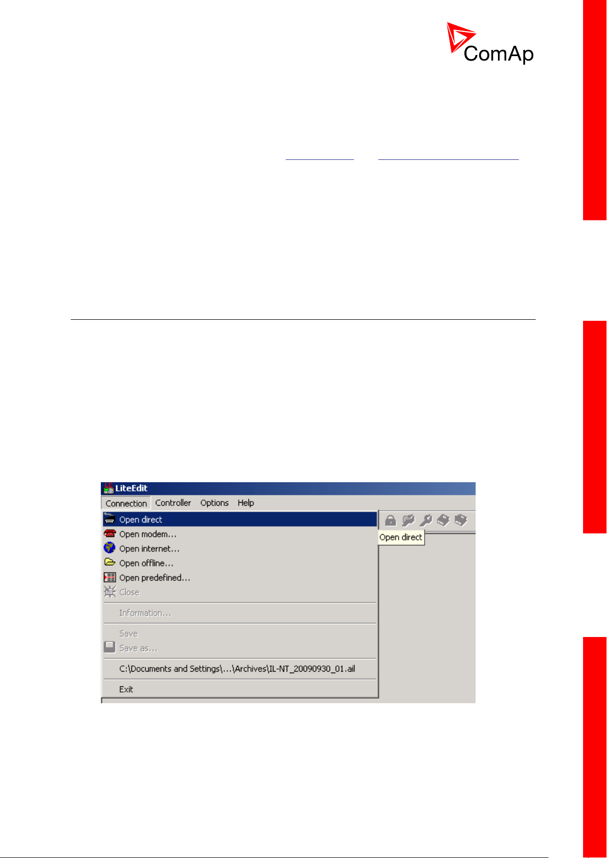
2.4.1 Open connection from LiteEdit
PC tool LiteEdit is used for monitoring, programming and configuration of ID-FLX-Lite controllers.
1. Go to menu Connection and select the type of connection you desire.
LITEEDIT - CONNECTION MENU
InteliDrive Lite, SW version 1.9
ID-FLX-Lite-1.9r1 Reference Guide.pdf, ©ComAp – August 2015
Page 15
15
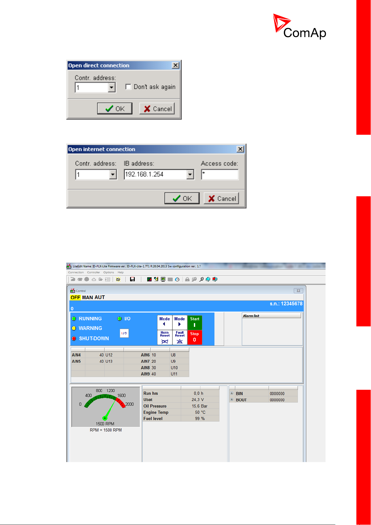
2. Enter controller address and further information depending on the selected connection type.
FOR DIRECT CONNECTION ENTER CONTROLLER ADDRESS
FOR INTERNET CONNECTION ENTER CONTROLLER ADDRESS, IP ADDRESS OF THE IB-LITE MODULE
FITTED IN THE CONTROLLER YOU WANT TO REACH, ACCESS CODE
3. You will see the Control window and you can continue with configuration of Setpoint, inputs,
outputs etc.
LITEEDIT CONTROL WINDOW
InteliDrive Lite, SW version 1.9
ID-FLX-Lite-1.9r1 Reference Guide.pdf, ©ComAp – August 2015
Page 16
16
NOTE:
For detail description of LiteEdit and InteliMonitor PC tools see the LiteEdit Reference Guide,
InteliMonitor Reference Guide and InteliDrive Communication Guide.
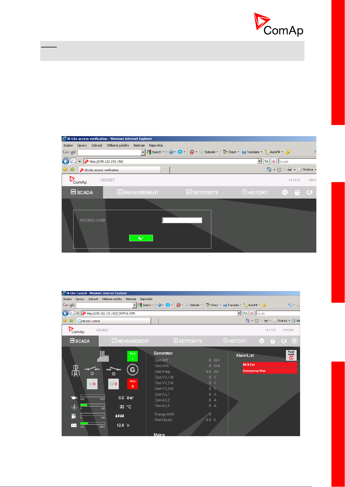
2.4.2 Open connection from web browser
It is possible to connect from a web browser to InteliDrive Lite controllers, mounted with IB-Lite module
(or IB-NT with specific conditions) and connected to internet.
1. Open web browser
2. Enter IP address from controller Comms Settings: IBLite IP Addr
3. Access verification page appears
ACCESS VERIFICATION PAGE
4. Enter access code and Scada page appears
SCADA PAGE
InteliDrive Lite, SW version 1.9
ID-FLX-Lite-1.9r1 Reference Guide.pdf, ©ComAp – August 2015
Page 17

17
NOTE:
You can try the WebServer from ComAp webpage. The access code is 0.
NOTE:
WebSupervisor is possible to use as a control and monitor tool. For access is necessary to be
registered. Connection setting and other information you can find in the WebSupervisor Reference
Guide.
2.4.3 Open connection from WinScope
WinScope is powerful PC tool for observation of controller’s states and measurements.
1. Go to menu Connection -> Open connection... and select the type of connection you desire
in Open connection window (Inteli controllers).
WINSCOPE - OPEN CONNECTION WINDOW
2. Proceed with selection of channels etc. according to WinScope Reference Guide
InteliDrive Lite, SW version 1.9
ID-FLX-Lite-1.9r1 Reference Guide.pdf, ©ComAp – August 2015
Page 18
18
2.5 Applications overview
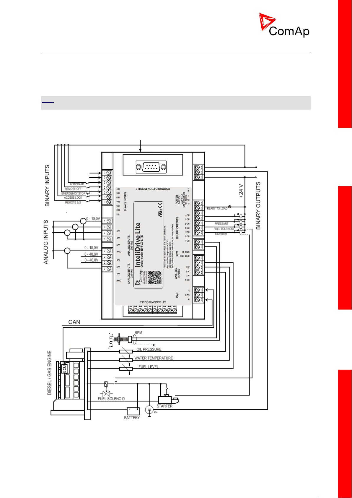
2.5.1 Single applications
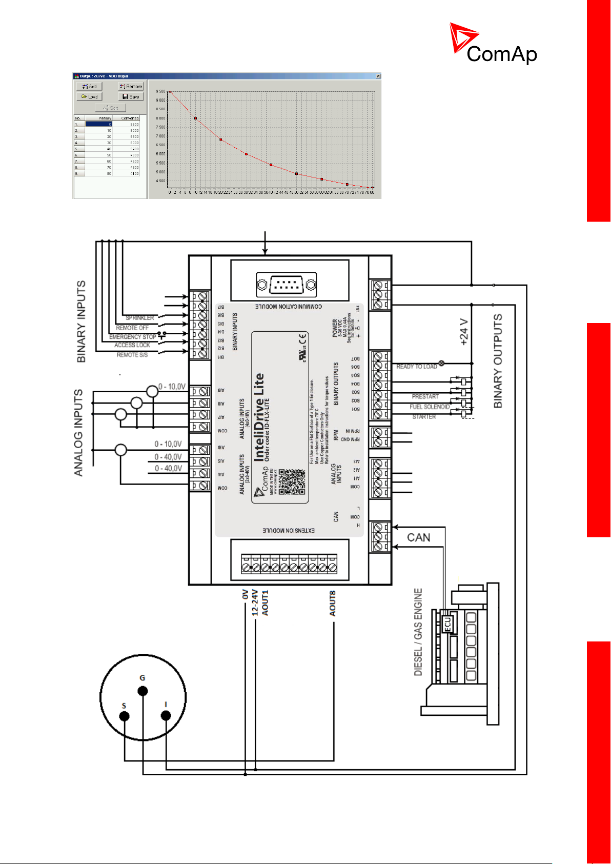
Basic wiring scheme for single engine, all engine data are transferred from ECU via CAN J1939
interface in example below.
HINT
The extension IGL-RA15 modules can be connected to CAN bus together with ECU.
APPLICATION DESCRIPTION
InteliDrive Lite, SW version 1.9
ID-FLX-Lite-1.9r1 Reference Guide.pdf, ©ComAp – August 2015
Page 19
19
3 Installation
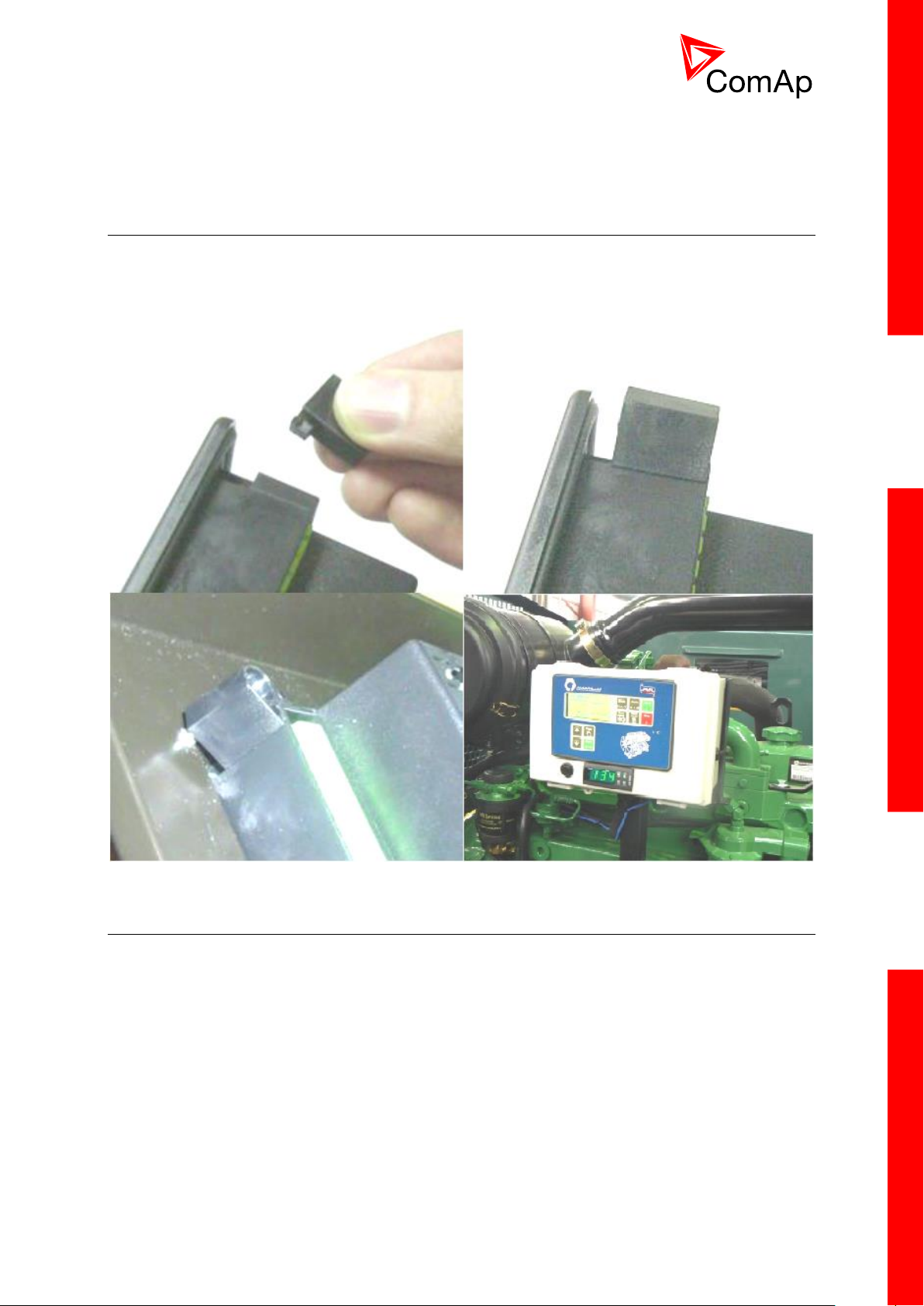
3.1 Mounting
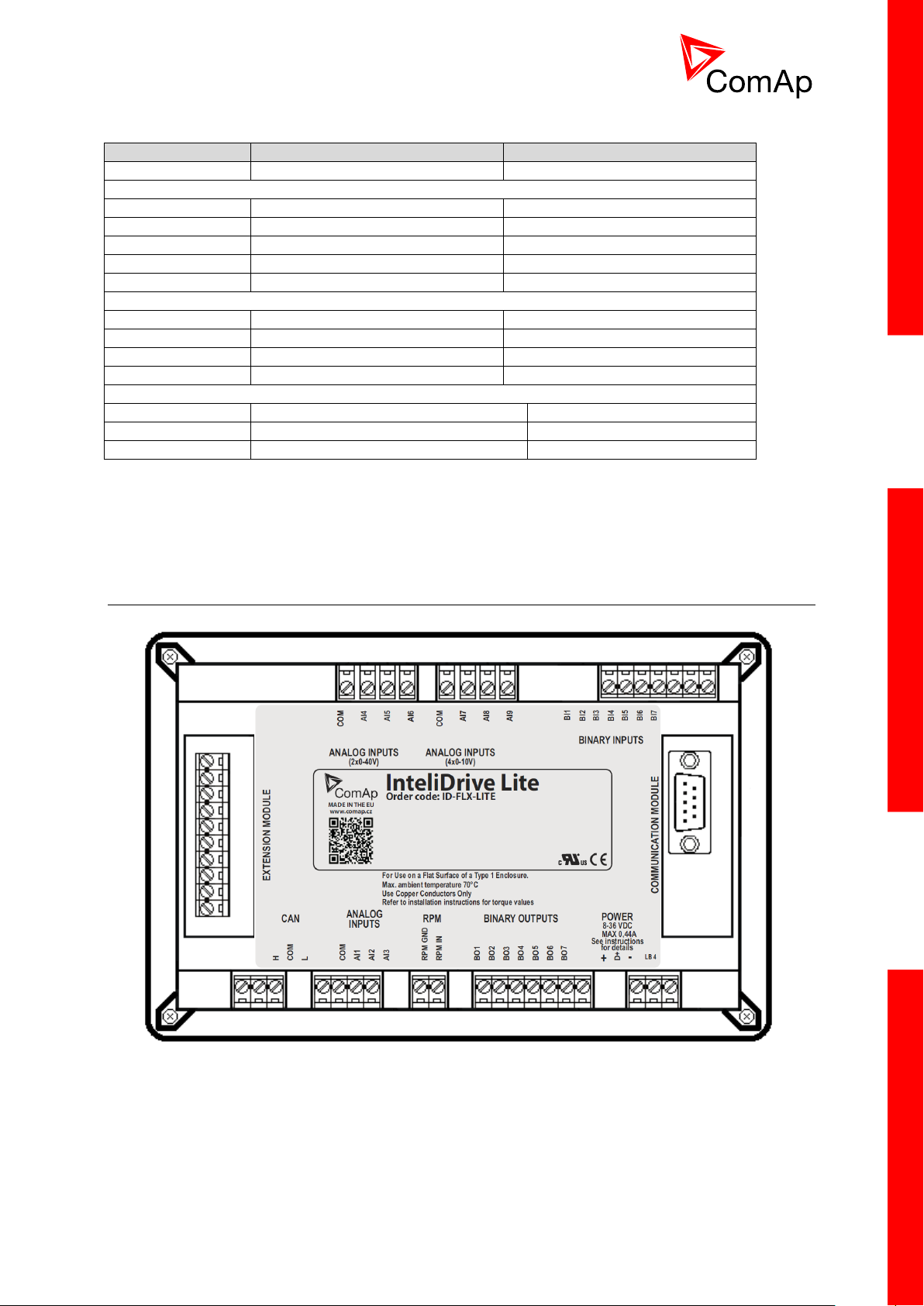
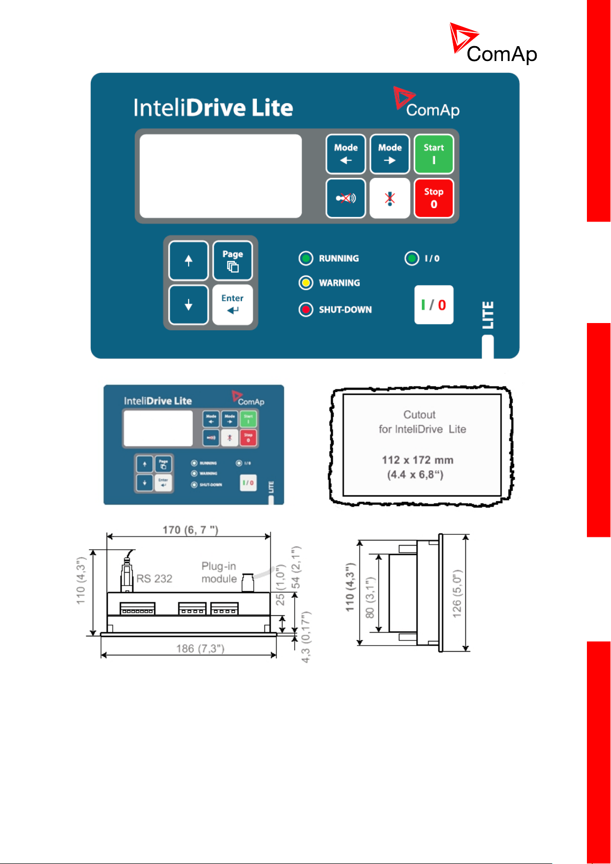
The controller is used to be mounted onto the switchboard door. Requested cutout size is
172x112mm. Use the screw holders delivered with the controller to fix the controller into the door as
described on pictures below.
3.2 Package contents
InteliDrive Lite controller is delivered in the box as one set containing the
ID-FLX-Lite controller programmed with default configuration
4x Fixing clips
Complete connectors (female) set for controller wiring
3.2.1 Software package
ID-FLX-Lite is distributed as ID-FLX-Lite-x.y.iwe package and it is compatible with the PC tool LiteEdit
x.y.z and ECU list-x.y, where x, y, z are numbers of software version. Find installation files on ComAp
web. Version of published files on the webpage are compatible each other.
InteliDrive Lite, SW version 1.9
ID-FLX-Lite-1.9r1 Reference Guide.pdf, ©ComAp – August 2015
Page 20
20
3.2.2 Components
Accessories
Description
Optional / Obligatory
ID-FLX-Lite
InteliDrive-Lite central unit
Obligatory
Communication plug-in
IL-NT RS232
RS232 communication card
Optional plug-in
IL-NT 232/485
Combined communication card
Optional plug-in
IL-NT S-USB
USB communication card
Optional plug-in
IB-Lite
Ethernet/Internet interface
Optional plug-in
IL-NT-GPRS
GSM/GPRS modem
Optional plug-in
Extension plug-in
IL-NT AOUT8
8 AOUT Gauge driver card
Optional plug-in
IL-NT AIO
4xAIN + 1x AOUT
Optional plug-in
IL-NT IO1
4xBIN + 4xAOUT
Optional plug-in
IL-NT BIO8
8x BIN or BOUT
Optional plug-in
External modules
IL-NT RD
Remote display
Optional external
IGL-RA15
Remote annunciator
Optional external
IB-NT
Communication module (3G, Ethernet)
Optional external
3.3 Terminal diagram and dimension
InteliDrive Lite, SW version 1.9
ID-FLX-Lite-1.9r1 Reference Guide.pdf, ©ComAp – August 2015
Page 21
21
InteliDrive Lite, SW version 1.9
ID-FLX-Lite-1.9r1 Reference Guide.pdf, ©ComAp – August 2015
Page 22
22
3.4 Extension plug-in modules
3.4.1 Extension plug-in modules installation
To insert the module, you must open the cover first (use screwdriver to open) and then insert the
module into slot. Once you have inserted it, the module will snap under plastic teeth. It is supposed to
be installed permanently. Should you need to remove it, the safest way is to remove whole back cover
and than remove module manually.
For configuration of extension plug-in modules go to LiteEdit and press button in Modify
configuration window.
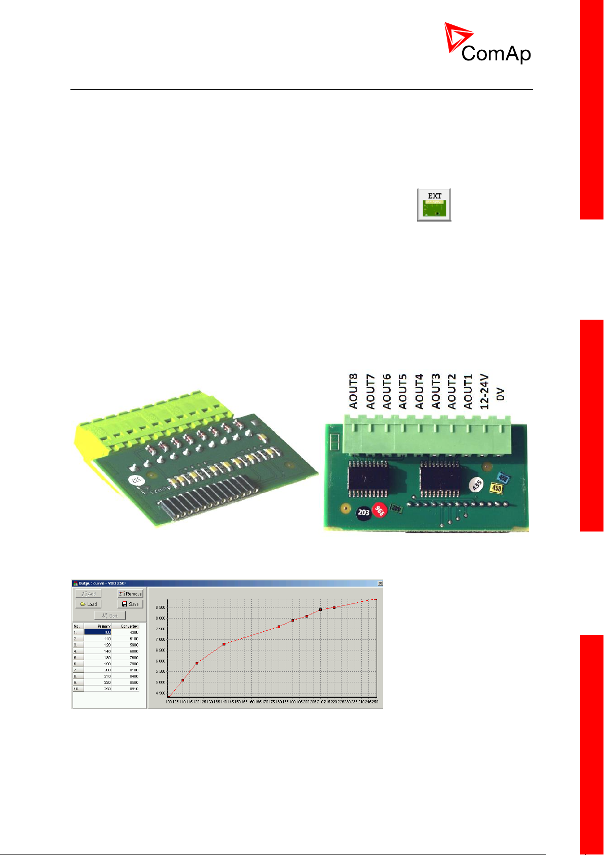
3.4.2 IL-NT AOUT8
IL-NT AOUT8 is optional plug-in card. Through this card can the controller drive up to 8 VDO style
industrial/automotive gauges. This is to provide visual indication of typically ECU values without
installing additional sensors on the engine. PWM signal emulates sensor which would be typically
mounted on the engine. Sensor/gauge curve and value are configured in LiteEdit PC tool. Any analog
value from the controller may be configured to the outputs. All outputs operate as PWM signal at
1200Hz.
Examples of default analog output curves:
InteliDrive Lite, SW version 1.9
ID-FLX-Lite-1.9r1 Reference Guide.pdf, ©ComAp – August 2015
Page 23
23
Example of wiring for Dacon gauges and IL-NT-AOUT8:
InteliDrive Lite, SW version 1.9
ID-FLX-Lite-1.9r1 Reference Guide.pdf, ©ComAp – August 2015
Page 24
24
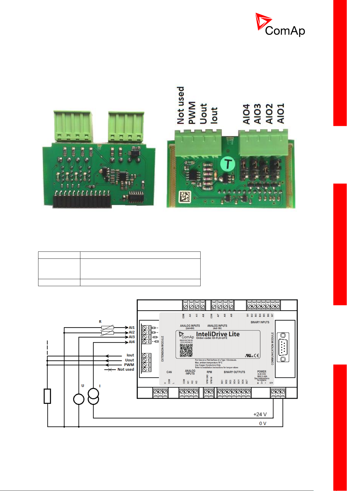
3.4.3 IL-NT AIO
AI1 – AI4
2600 Ohm / 4V / 20 mA
Iout
Uout
PWM
0 – 20 mA (max 22mA) max 100 Ohm load
0 – 4,5V (max 10mA)
PWM 5V / 15mA / 500 Hz
Not used
Do not connect!
IL-NT AIO is optional plug-in card. This card offers additional four analog inputs and one analog
output. Analog inputs can be use for different types of sensor (resistive, current and voltage) and
variable analog output, which can be used as PWM. Adjustment of extension plug-in modul is possible
via LiteEdit too.
Type of analog input is selectable by jumper. Each analog input has own line of jumper position. The
top position (closest to green conector on the pic above) is for resistive input, central position for
voltage input and lowest position is for current input.
InteliDrive Lite, SW version 1.9
ID-FLX-Lite-1.9r1 Reference Guide.pdf, ©ComAp – August 2015
Page 25
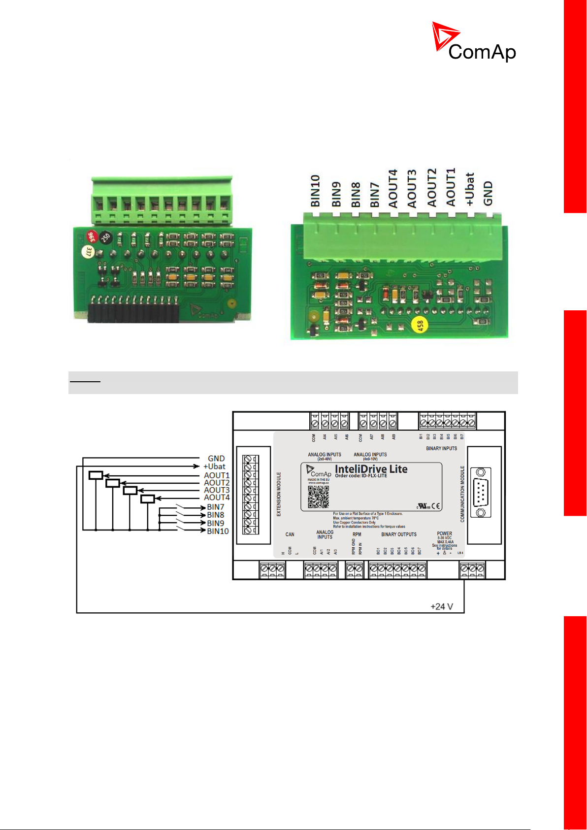
25
3.4.4 IL-NT IO1
IL-NT IO1 is optional plug-in card. Through this card controller can drive up to 4 propotional valves
and to use 4 additional binary inputs. The 0V (GND) terminal is internally wired with battery minus
internally, the 12-24V (+Ubat) terminal is wired to battery plus power supply of InteliDrive Lite
controller.
There should be, not more than 1V, lower voltage compare to adjusted % of +Ubat voltage.
NOTE:
Analog output shorted to ground more than one second can damage the output circuit.
3.4.5 IL-NT BIO8
IL-NT BIO8 is optional plug-in card. Through this card controller can use up to 8 additional binary
inputs or outputs. At least one Batt- terminal has to be connected to battery minus power supply of
InteliDrive controller, if at least one binary output is configured. In case more than 4 binary outputs are
configured is necessary to connect both Batt- terminals.
InteliDrive Lite, SW version 1.9
ID-FLX-Lite-1.9r1 Reference Guide.pdf, ©ComAp – August 2015
Page 26

26
3.5 Communication modules
3.5.1 IL-NT RS232
IL-NT RS232 is optional plug-in card, which enables InteliDrive Lite controller for RS232 serial
communication. This is required for computer or ModBus connection. The card has to be inserted into
the expansion “Communication module” slot back on the controller, similarly to extension modules.
InteliDrive Lite, SW version 1.9
ID-FLX-Lite-1.9r1 Reference Guide.pdf, ©ComAp – August 2015
Page 27
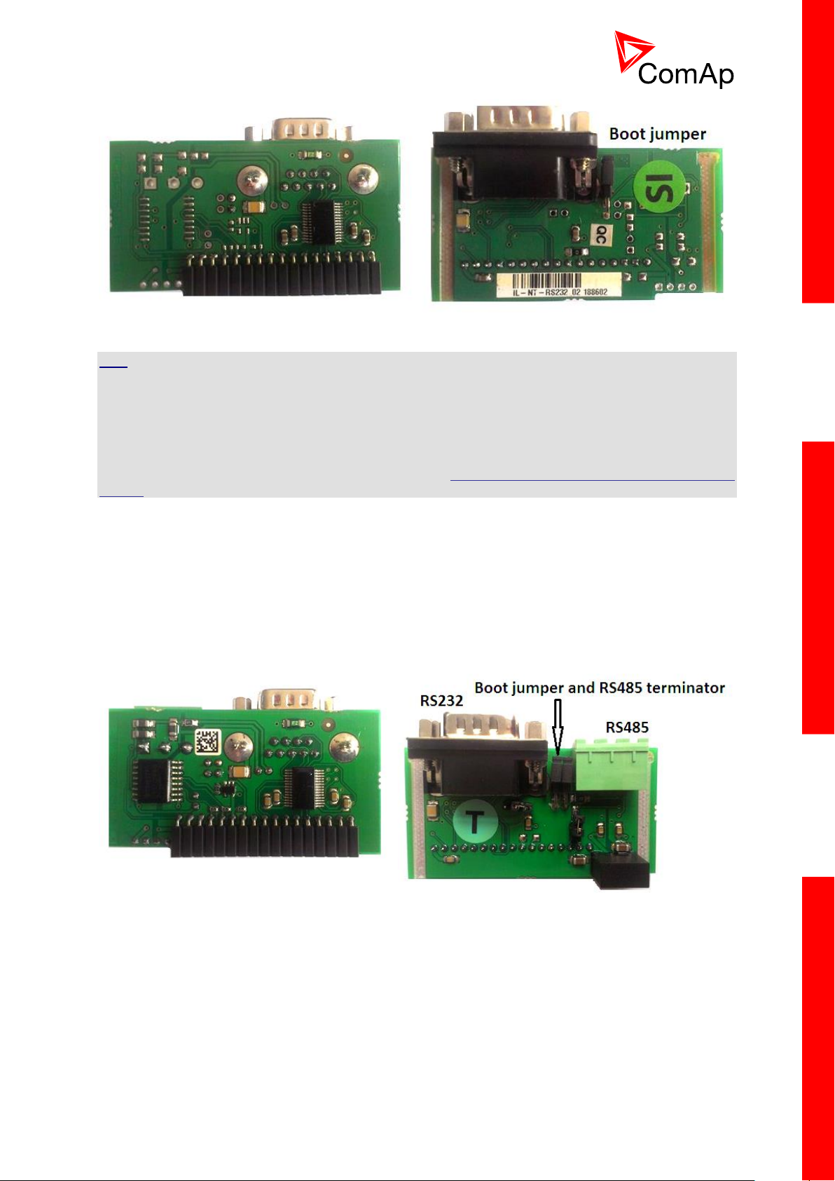
27
HINT
Boot jumper programming – In case of interrupted programming or other software failure is possible to
use the boot jumper programing to restore controller to working order. Connect the controller to PC,
run LiteEdit and wait until connection bar at bottom turns red. Than run programming process via
menu Controller -> Programming and cloning – Programming. Select correct firmware and confirm
dialog. Than follow instructions in LiteEdit.
Or follow video guide “Boot Jumper Programming“ at http://www.comap.cz/support/training/training-
videos/
3.5.2 IL-NT RS232-485
IL-NT RS232-485 is optional plug-in card, which enables InteliDrive Lite controller RS232 and RS485
serial communication. This is required for computer or Modbus connection. The IL-NT RS232-485 is a
dual port module with RS232 and RS485 interfaces at independent COM channels. The RS232 is
connected to COM1 and RS485 to COM2. Adjustment of communication type, baud rate etc. is via
Comms Setting group of setpoint in LiteEdit or the controller screen.
3.5.3 IL-NT S-USB
IL-NT S-USB is optional plug-in card to enable communication of InteliDrive controller via USB port.
This is required for computer or Modbus connection. This module contains USB slave port, which is
connected internally to the COM1 of the controllers. It is designed as an easy removable service
module.
This module requires a FTDI USB Serial converter driver installed in the PC. The driver creates a
virtual serial port (COM) in the PC, which must be used in LiteEdit as communication port when a
connection is being opened.
InteliDrive Lite, SW version 1.9
ID-FLX-Lite-1.9r1 Reference Guide.pdf, ©ComAp – August 2015
Page 28
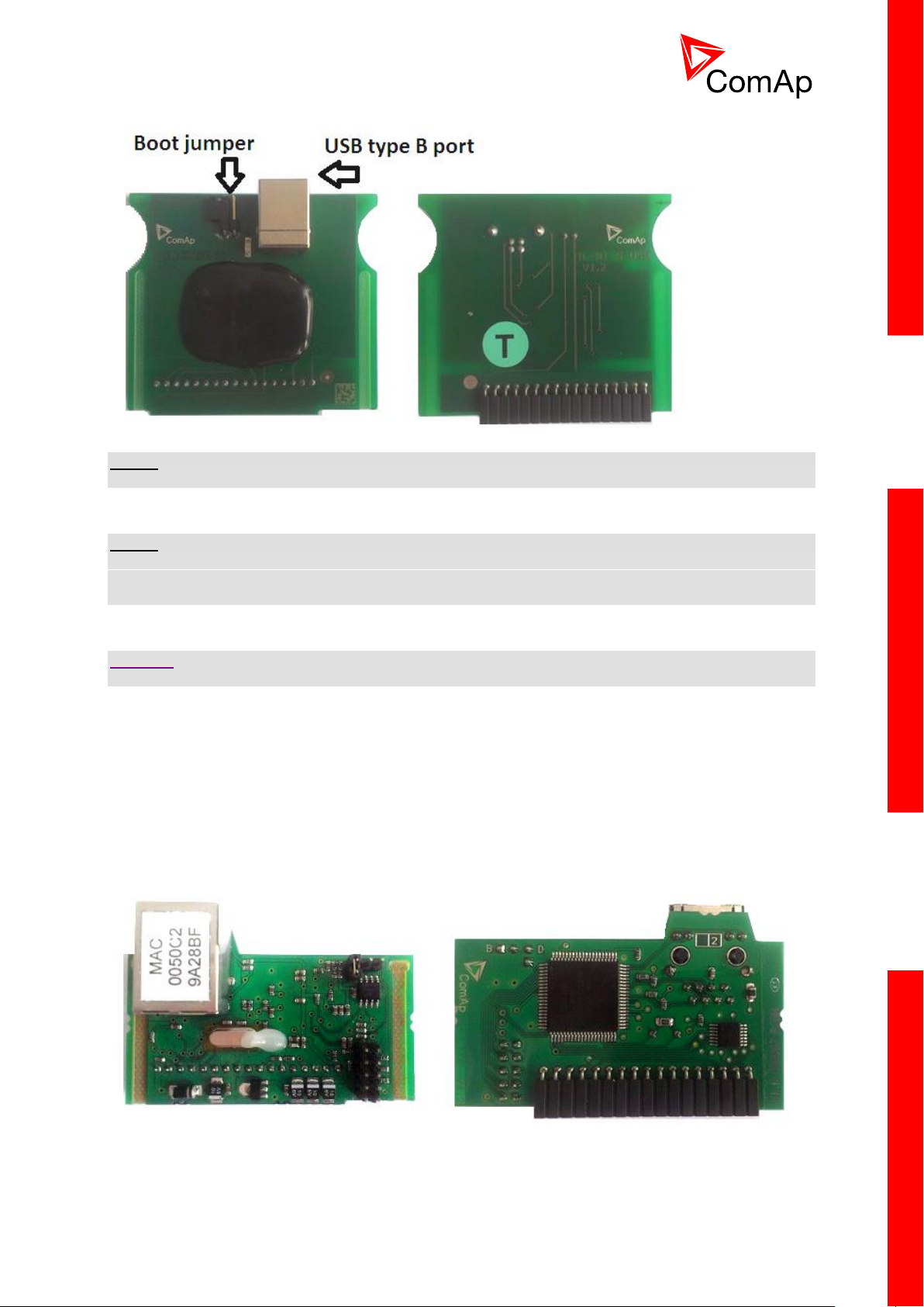
28
NOTE:
The FTDI driver is installed together with LiteEdit.
NOTE:
When the USB cable from the controller is plugged-in first time into different USB ports on the PC
including USB hubs, it can be recognized as new hardware and the drivers are installed again with
different number of the virtual serial port.
CAUTION!
Use shielded USB cable only! (ComAp order code: USB-LINK CABLE 1.8m)
3.5.4 IB-Lite
IB-Lite is a optional plug-in card with Ethernet 10/100 Mbps interface in RJ45 connector. The card is
internally connected to both COM1 and COM2 serial channels and provides an interface for
connecting a PC with LiteEdit or InteliMonitor through Ethernet network, for sending active e-mails and
for integration of the controllers into a building management (Modbus/TCP protocol).
This card also enables to monitor and control the consumption engines over web browser from any
location with internet access using appropriate security measures.
InteliDrive Lite, SW version 1.9
ID-FLX-Lite-1.9r1 Reference Guide.pdf, ©ComAp – August 2015
Page 29
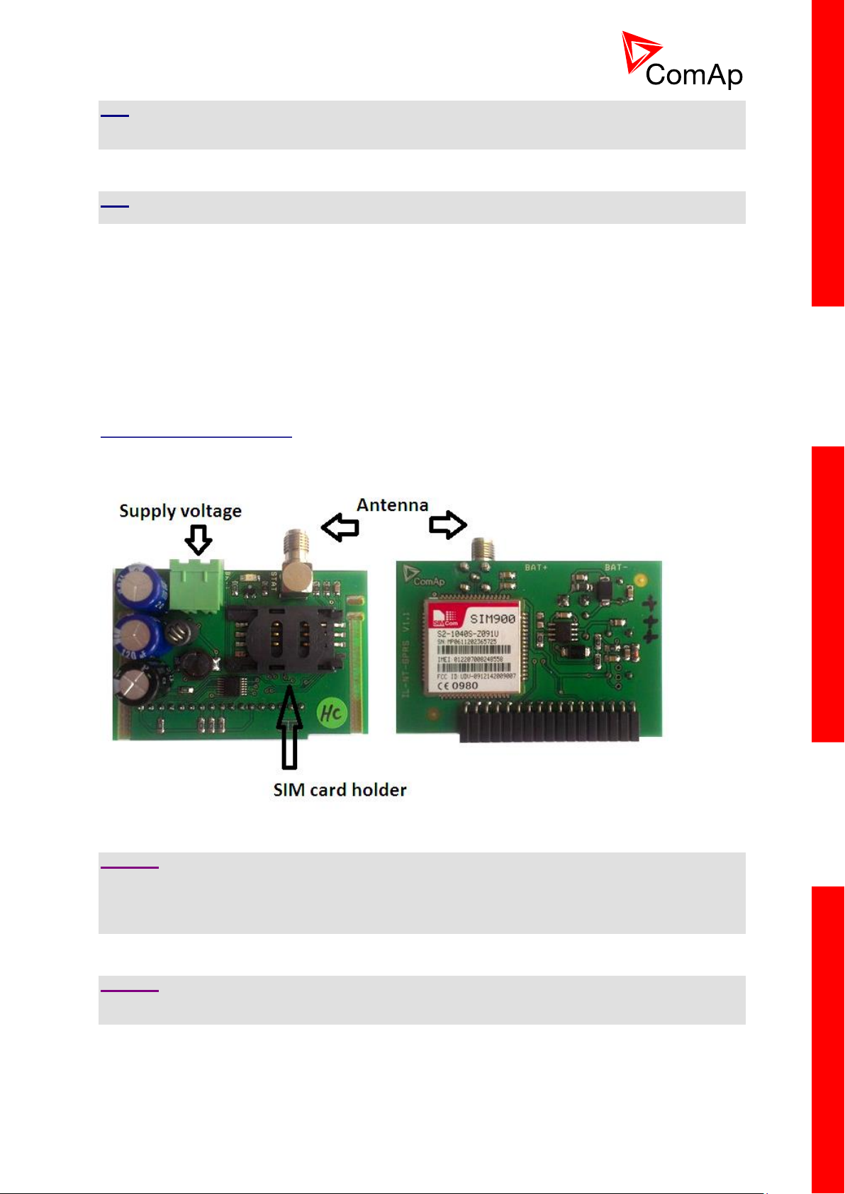
29
HINT
Use Ethernet UTP cable with RJ45 connector for connection of the module into your ethernet network.
The module can be also connected directly to a PC using cross-wired UTP cable.
HINT
The module requires configuration settings before usage. See IB-Lite 1.x Reference Guide.
3.5.5 IL-NT GPRS
IL-NT GPRS is optional plug-in card, which works as GSM/GPRS modem which can work in two
modes of operation based on settings in setpoint COM1 Mode.
• Settings DIRECT = module works in GPRS network and enables connection via AirGate to LiteEdit
and WebSupervisor as well as sending SMS alarms.
• Settings MODEM = module works as standard GSM modem enabling CSD (Circuit Switch Data)
connection to controller with LiteEdit or other ComAp PC SW and sending alarm SMSes.
Module is usually used for connection to remote monitoring and controlling system WebSupervisor
http://websupervisor.comap.cz or to PC tools. Module is capable of sending alarm SMS based on
settings in SMS/Email setpoint group.
CAUTION!
Any manipulation with plug-in module shall be done with disconnected power supply to both controller
and module. Power supply shall be switched on also is same time to both module and controller. Fail
to follow these instructions (power supply active only in controller or only in module) can lead to
module or controller failure!
CAUTION!
GPRS and CSD connection is not suitable for firmware update process, kindly used wired connection
instead like RS232, USB, RS485 or ethernet via IB-Lite!
InteliDrive Lite, SW version 1.9
ID-FLX-Lite-1.9r1 Reference Guide.pdf, ©ComAp – August 2015
Page 30

30
HINT
Quick guide how to start using this module is in chapter Remote Communication - Short guide how to
start using IL-NT-GPRS module or on ComAp webpage http://www.comap.cz/products/detail/IL-NT-
GPRS
HINT
Use of this plug-in brings WSUP Locate function. This function allows monitoring actual engine
position based on GSM signal information. The position is automatically updated and stored in WSV
history. You can track the position of the engine in WebSupervisor even in history.
HINT
Unlike GPS system, the function works indoor or wherever the GSM signal is. Precision of
localizationis not as precise as with GPS and depends on density of operator’s GSM/BTS tower
around the controller.
3.6 Remote modules
Remote modules allow monitoring and displaying of values and states away from main controller.
3.6.1 IL-NT RD (SW)
IL-NT RD is remote display software for a controller. Remote display provides the same control and
monitoring functions as controller itself. Remote display for InteliDrive controllers uses standard
InteliDrive Lite controller with Remote display software. No further programing of the display is
required – unit is self configurable from the main controller.
All remote display’s LEDs show the same state as corresponding LEDs on master controller. Front
panel buttons on both controllers work in the same way. Engine can be controlled from remote display
as well as from master controller. User can switch screens, set password, change setpoints and view
history records.
All IL-NT RD screens Init, Measure, Setpoints and History display the same data like in the master
controller.
Master device is always able to work without connected Remote display.
Interruption of the serial line between master device and Remote display has no effect to the master
controller.
If the serial line between master device and remote display is interrupted, or communication cannot be
established, remote display shows it’s Init screen and message “Trying” and all LED’s are off.
Once remote display finds compatible master it shows “Preparing” and downloads configuration table
from master controller.
After the configuration from master is downloaded remote display jump to master controllers Init
screen and all LEDs and blinking.
It is possible to switch to remote displays Init screen to check it’s version and serial number of used
controller and communication status by pressing PAGE button for 3 seconds
InteliDrive Lite, SW version 1.9
ID-FLX-Lite-1.9r1 Reference Guide.pdf, ©ComAp – August 2015
Page 31

31
WARNING!
It is highly recommended to use the same type and model of controller for master and remote display.
Only in such case is assured the proper function of all buttons, LED diods and display. Another
combinations of HW types and models from Master controller and remote display are neither
supported nor tested
IL-NT RD software installation
The IL-NT-RD remote display firmware is installed in the same way as any other InteliDrive firmware
using LiteEdit. Please see LiteEdit Reference guide for details about upgrading firmware. IL-NT-RD
consists only firmware, not an archive.
However when there is IL-NT-RD firmware installed in the controller the procedure to install back the
original standard firmware is following:
Open any type of online connection.
DDE server will try to open the connection, but it will fail and write red error message in the
status bar.
In this moment go to CONTROLLER -> PROGRAMMING AND CLONING -> PROGRAMMING and
select proper firmware you want program to the controller. Choosing the wrong type of
firmware may result in non-functional controller.
Press "OK" button to programm the firmware to the controller.
It may be required to switch off power supply of the controllers, close the boot jumper and
switch on controller again. Follow the information windows accordingly.
After programming is finished (it may be required to power off controller, open the boot jumper
and power it on again) open configuration window and perform the configuration process
manually. There is no compatibility of the configuration between different firmware versions.
In some cases the "wrong setpoints" message can occur in the DDE server status line and
controller is blocked showing "Init" state. Use CONTROLLER -> RESET FROM INIT STATE menu
item to put the controller to normal operation. Be sure you have checked all setpoints before.
CAUTION!
Check the statistic value "Engine hours" after firmware upgrade. Change of statistical values if
necessary is possible only by LiteEdit software (password is required).
IL-NT-RD Wiring
IL-NT-RD can be connected to InteliDrive Lite controller via RS232 or RS485 communication line. It is
possible to connect only up to two remote displays to one master controller, if they are using different
communication COMs. It is not supported to connect two or more remote displays to one
communication line, eg. RS485. It is possible to monitor only one master controller from one remote
display at the time.
Connection proces:
Remote display after power on automaticaly starts to search for any master controller connected. It
starts to search on COM1 from master controllers address 1 to 32 and later on COM2 from address 1
to 32. Remote display tries two communication speeds 38400 bps and 56000bps.
During this process is displayed text “Detecting…” on screen and progress bar below counts from 0 to
100%. This process takes approx. 10-15 seconds. Than is 5 seconds pause and process continues
again until compatible master controller is found.
Not supported types of controllers, not supported application, or controllers that are not properly
comunicating are skipped during the search.
Controller type selection:
IL-NT-RD automatically detects controller type.
InteliDrive Lite, SW version 1.9
ID-FLX-Lite-1.9r1 Reference Guide.pdf, ©ComAp – August 2015
Page 32

32
Troubles with connection:
There are few reasons why remote display can not connect with master controller:
1. Not supported type of controller connected (Eg. IGS-NT, ID-DCU, IC-NT, IGS-CU, etc.)
2. Not supported firmware in master controller
3. Configuration table error in master controller
4. Wrong settings of setpoint COMx Mode in master controller
5. Wrong connection, wiring, communication fail
Communication lines:
It is connected with the controller via IL-NT-RS232 communication modules using RS232 line (up to
10m). Longer distances (up to 1200m) are possible using IL-NT-RS232-485 communication module or
when RS232/RS485 converters are used.
It is possible to make a RS232 direct connection with IL-NT-RS232 module on one side and IL-NTRS232-485 module on the other side.
3.6.2 IGL-RA15
The remote announciator IGL-RA15 can be connected to the InteliDrive unit via CAN bus. Any of the
binary outputs can be configured (using LiteEdit) to each LED diode on the RA15. The module can be
also enabled or disabled using LiteEdit.
If IGL-RA15 remote announciator is not communicating with a controller via CAN bus, it activates a
warning.
HINT
See the documentation of IGL-RA15 for the technical description.
InteliDrive Lite, SW version 1.9
ID-FLX-Lite-1.9r1 Reference Guide.pdf, ©ComAp – August 2015
Page 33

33
3.6.3 IB-NT
Internet bridge allows different type of communication and multiple controllers communication. Single
InteliDrive Lite controller is possible to connect via serial line RS232. For multiple controllers
connection is necessary to use RS485 communication port.
IB-NT offers direct, internet, AirGate and cellular network type of communication.
HINT
See the documentation of IB-NT for the detail description.
InteliDrive Lite, SW version 1.9
ID-FLX-Lite-1.9r1 Reference Guide.pdf, ©ComAp – August 2015
Page 34

34
4 Putting it into operation
4.1 How to install
To ensure proper function:
Wiring for binary inputs and analog inputs must not be run with power cables.
Analog and binary inputs should use shielded cables, especially when length >3m.
NOTE:
During the configuration of controller or setpoints changes is required a password to the controller.
The default password from ComAp is “0”.
4.1.1 Grounding
To ensure proper function:
Use cable min. 2,5mm2.
Brass M4x10 screw with star washer securing ring type grounding terminal shall be used.
The negative “-“ terminal of the battery has to be properly grounded.
Switchboard and engine has to be grounded in common spot.
Use cable as short as possible to the grounding point.
4.1.2 Wiring
Tightening torque, allowable wire size and type, for the Field-Wiring Terminals:
Based on terminal type:
PA256:
Specified tightening torque 0.5Nm (4.4 In-lb)
2EDGK:
Specified tightening torque 0.4Nm (3.5 In-lb)
For field type terminals:
Use only diameter 2.0-0.5mm (12-26AWG) conductor, rated for 75°C minimum.
For Generator Voltage terminals
Use only diameter 2.0-0.5mm (12-26AWG) conductor, rated for 90°C minimum.
Use copper conductors only.
4.1.3 Power supply
Use minimally power supply cable of 1.5mm2.
CAUTION!
Maximum continuous DC power supply voltage is 36VDC.
InteliDrive Lite, SW version 1.9
ID-FLX-Lite-1.9r1 Reference Guide.pdf, ©ComAp – August 2015
Page 35

35
Maximum allowable DC power supply voltage is 39VDC.
The InteliDrive Lite’s power supply terminals are protected against large pulse power disturbances.
When there is a potential risk the controller being subjected to conditions outside its capabilities, an
outside protection devise should be used.
HINT
The InteliDrive Lite controller should be grounded properly in order to protect against lighting strikes!!
The maximum allowable current through the controller’s negative terminal is 4A (this is dependent on
binary output load).
For the connections with 12VDC power supply, the InteliDrive Lite includes internal capacitors that
allow the controller to continue operation during cranking if the battery voltage dip occurs. If the
voltage before dip is 12V, after 150ms the voltage recovers to 7V, the controller continues operating.
During this voltage dip the controller screen backlight can turn off and on but the controller keeps
operating.
It is possible to further support the controller by connecting the external capacitor or I-LBA module.
The capacitor size depends on required time. It
shall be approximately thousands of uF
(microFarads). The capacitor size should be
5000uF to with stand 150ms voltage dip under
following conditions:
Voltage before dip is 12V, after 150ms the
voltage recovers to minimum allowed voltage
i.e. 8V
The I-LBA module ensures minimaly 350ms
voltage dip under following conditions:
RS232 and other plug-in module is connected.
Voltage before dip is 12V and after 350ms the
voltage recovers to minimum allowed voltage
5V. The I-LBA enables controller operation
from 5V (for 10 to 30 sec). The wiring
resistance from battery should be up to 0.1
Ohm for I-LBA proper function.
4.1.4 Power supply fusing
A one-amp fuse should be connected in-line with the battery positive terminal to the controller and
modules. These items should never be connected directly to the starting battery.
Fuse value and type depends on number of connected devices and wire length. Recommended fuse
(not fast) type - T1A. Not fast due to internal capacitors charging during power up.
InteliDrive Lite, SW version 1.9
ID-FLX-Lite-1.9r1 Reference Guide.pdf, ©ComAp – August 2015
Page 36

36
4.1.5 Binary output protections
Do not connect binary outputs directly to DC relays without protection diodes, even if they are not
connected directly to controller outputs.
4.1.6 Magnetic pick-up
To ensure proper function:
Use a shielded cable
Be aware of interference signal from Speed governor, if one speed pick up is used.
If engine will not start:
Check ground connection from pick-up to controllers, eventually disconnect ground connection
to one of them
Galvanic separate InteliDrive Lite RPM input using ComAp separation transformer RPM-ISO
(1:1)
Use separate pick-up for Speed governor and InteliDrive Lite
InteliDrive Lite, SW version 1.9
ID-FLX-Lite-1.9r1 Reference Guide.pdf, ©ComAp – August 2015
Page 37

37
Input
Range
Default use
Configurability
of default use
AIN1
0 - 2,4k
Oil pressure
NO
AIN2
0 - 2,4k
Engine temperature
YES
AIN3
0 - 2,4k
Fuel level
YES
AIN4
0 - 40V
Not used - free
YES
AIN5
0 - 40V
Not used - free
YES
AIN6
0 - 10V
Not used - free
YES
AIN7
0 - 10V
Not used - free
YES
AIN8
0 - 10V
Not used - free
YES
AIN9
0 - 10V
Not used - free
YES
HINT
If RPM > 2 then the controller is in the state Not ready and the engine will not be allowed to start.
4.2 Analog inputs
On the InteliDrive Lite controller nine analog inputs are available. See the two tables here bellow with
specific characteristics.
All here mentioned properties can be modified by LiteEdit PC tool only, in the window Modify
4.2.1 Table of controller analog inputs
HINT
The nominal range of Analog inputs measuring resistivity is 0- 2,4 kOhm, nevertheless the input is
able to measure up to 15 kOhm, but with lower precision.
HINT
When Engine Control Unit is connected, it is possible to read InteliDrive Lite Analog inputs values
AIN1, 2, 3 from CAN bus (J1939).
InteliDrive Lite, SW version 1.9
ID-FLX-Lite-1.9r1 Reference Guide.pdf, ©ComAp – August 2015
Page 38

38
4.2.2 Table of analog inputs options
LiteEdit
Modify
Possibility
Type
Not used
Alarm
Monitoring
Analog input isn’t used
Analog input is used for monitoring and protection
Analog input is used only for monitoring
Name
… text
Name in history
Up to 14 ASCII characters
Up to 4 ASCII characters for the name used in history records
Config
Analog
Binary
Tri state
ECU
Analog measuring in specified range.
Binary: open/close - threshold 750 or 7VDC (AIN6-AIN9)
Three (Triple)-state: open/close - threshold 750 (only AIN1-AIN3),
failure <10 or > 2400
Only for AIN1, 2 values are read from ECU unit
Alarm
properties
Direction
Under limit
Under step. Sensor fail does not activate protection.
Over limit
Overstep. Sensor fail does not activate protection.
UnderLimit+Fls
Under step and Sensor fail activates protection.
OverLimit+Fls
Overstep and Sensor fail activates protection.
Window prot.
Combination of Under and Over protection at the same analog input
Type
Sensor fail
Warning
Wrn+Sd
CoolDown
Engine running
only
Check box: Alarms are valid only for running engines, if box is
checked
Sensor
Sensor name
… text
Resulotion: number of decimal points
Dimension: bar, %, °C, etc.
Table and graph: customize curves
Contact
type
NC
NO
Valid only for binary and three-state inputs
Valid only for binary and three-state inputs
User curves “Points” are adjustable in LiteEdit PC tool.
InteliDrive Lite, SW version 1.9
ID-FLX-Lite-1.9r1 Reference Guide.pdf, ©ComAp – August 2015
Page 39

39
Analog inputs 1, 2, 3, 8 and 9 has separate set points for two levels alarm setting and delay for
activation of alarm.
Analog input 4, 5, 6 and 7 has special „window“ protection. It is possible to adjust Low and High level
with alarm setting Wrn and Sd for each of level. Two delay setpoints are adjustable for Low and High
level. (See Practical example below)
Window protection is necessary to adjust in Modify->Alarm properties->Direction.
Analog input alarm levels and delay adjust in Engine protect group of Setpoints.
HINT
In Alarm list and History is displayed only Wrn and Sd for matching analog input. There isnt visible
direction of protection Low or High.
Practical example of - Class C - Window protection :
Pressure sensor is configured on the analog input 7 and is placed on the intake pipe. There are
needed two level protection. Low level protection against suction from the tank without liquid, that
could destroy pump. High level protection against high liquid pressure in pipe, which could destroy
filters against impurity installed between tank and pump.
AIN7 LowWrn = 2bar
AIN7 LowSd = 1bar
AIN7 LowDel = 5s
AIN7 HighWrn = 4bar
AIN7 HighSd = 5bar
AIN7 HighDel = 2s
HINT
Class C protection is working and LowWrn, LowSd, LowDel, HiWrn, HiSd, HiDel setpoints are visible
only when corresponding AIN is configured in Modify->Alarm properties-> Direction-> Window prot.
InteliDrive Lite, SW version 1.9
ID-FLX-Lite-1.9r1 Reference Guide.pdf, ©ComAp – August 2015
Page 40

40
Standard connection of three resistive sensors
to analog inputs.
Mixed connection of InteliDrive Lite analog
inputs:
AI1 – binary input
AI2 – three state input
AI3 – analog resistive input
4.2.3 Connection of InteliDrive Lite analog inputs
InteliDrive Lite, SW version 1.9
ID-FLX-Lite-1.9r1 Reference Guide.pdf, ©ComAp – August 2015
Page 41

41
4-20mA/100
0-20mA/100
0-20mA/(-20 - +120°C)
Ohm
Converted
Note 1
Note 2
Note 3
Note 4
120
0 mA
0%
-20°C
170 0 0%
4 mA
20%
8°C
200
13 22°C
230
25
25%
8 mA
40%
36°C
280
38 50°C
330
50
50%
12 mA
60%
64°C
390
63 78°C
460
75
75%
16 mA
80%
92°C
560
88 106°C
690
100
100%
20 mA
100%
120°C
Analog inputs are designed for resistive sensors with resistance in range of 0 to 2,4k.
To ensure a proper function use shielded cables, especially for length over >3m.
As binary input
Open, close state are detected, threshold level is 750.
As three state input
Open, close and failure state are detected. Threshold level is 750, failure is detected when circuit
resistance is <10 or > 2400.
Unused analog inputs
Configure Type = Not used
4.2.4 Current output transducers
InteliDrive Lite analog inputs are mainly designed for resistor sensors.
In special case transducers to 4-20mA output can be used for oil measuring (10.0Bar or 6.0Bar). Use
predefined 4-20mA/100 or 4-20mA/60 sensors.
This method reduces the input resolution by less than 50%. Some types of transducers are not
suitable for connection to InteliDrive Lite analog inputs because of influencing by InteliDriveLite analog
input.
Default current sensor characteristic
Use with external resistor 120 ohms
Note 1 - % range for 4-20 mA input
Note 2 - range 0-20 mA
Note 3 - % range for 0-20 mA input
Note 4 - characteristic 0-20 mA / (-20 - +120 °C)
4.2.5 Analog input extension measurement (0 - 70V, 4 - 20mA)
On each analog input there is a possibility to connect voltage or current output sensor instead of
resistive one. Recommended wiring connection for these measurements are bellow.
InteliDrive Lite, SW version 1.9
ID-FLX-Lite-1.9r1 Reference Guide.pdf, ©ComAp – August 2015
Page 42

42
Voltage output sensor - connection
Analog input
R1
R2
Curve
0 - 10V
150Ω [1%,0,5W]
100Ω [1%,0,5W]
AI 0-10V.CRV
0 - 30V
680Ω [5%,2W]
100Ω [1%,0,5W]
AI 0-30V.CRV
0 - 65V
1500Ω [5%,3W]
100Ω [1%,0,5W]
AI 0-65V.CRV
4 - 20mA
R = 160Ω [1%,0,5W]
AI 4-20mA.CRV
Vout [V]
0 1 2 3 4 5 6 7 8 9 10
P [bar]
0
0,6
1,2
1,8
2,4 3 3,6
4,2
4,8
5,4
6
Current output sensor – connection
Table with recommended values
CAUTION!
Please note that external resistors disconnection, connection incorrect resistors or input voltage value
during operation may cause an analog input destruction.
Practical example: VDO pressure sensor 0 – 6bar with linear voltage output 0 – 10V
Conversion table
Modify one of analog input in LiteEdit configuration and load curve AI 0-10V.CRV
Than you can change resolution and measured value name witch is default displayed at V (volts).
For example if you have connected pressure sensor and his output voltage is 5V for pressure 3bar
you can change value ‘V’ in column “Dim:” to ‘Bar’ and by sensor specification adjust all corresponding
values in this column. In this case you can change the value at row 6. from 5 to 3.
InteliDrive Lite, SW version 1.9
ID-FLX-Lite-1.9r1 Reference Guide.pdf, ©ComAp – August 2015
Page 43

43
When you finish with adjusting the values click OK and Write to controller.
4.3 Binary inputs and outputs
InteliDrive Lite, SW version 1.9
ID-FLX-Lite-1.9r1 Reference Guide.pdf, ©ComAp – August 2015
Page 44

44
4.4 Analog outputs
First option is extension plug-in card IL-NT AOUT8. This card provides eight Pulse-With-Modulation
(PWM) outputs. These are intended to drive VDO style analog gauges. This is to provide visual
indication of typically ECU values without installing additional sensors on the engine. PWM signal
emulates sensor which would be typically mounted on the engine.
Second option is extension plug-in card IL-NT-AIO. This card provides one current or voltage or PWM
output.
Any value from controller may be configured to the outputs. Use LiteEdit PC tool to configure
corresponding sensor/gauge curve and value selection.
4.4.1 Default analog output curves
InteliDrive Lite, SW version 1.9
ID-FLX-Lite-1.9r1 Reference Guide.pdf, ©ComAp – August 2015
Page 45

45
4.5 Remote modules - CAN bus connection
4.5.1 Connection rules
CAN bus line must be connected in series, from one unit to the next (no star, no cable stubs, no
branches) both ends must be by the 120Ohm (internal or external) resistor terminated. Maximal CAN
bus length is up to 200 meters.
For CAN data cables details see chapter Technical data - Communication interface.
CAN cable shielding is conneced to InteliDrive Lite COM terminal.
InteliDrive Lite contains internal fix 120Ohm resistor and must be located on the CAN bus end.
It is possible to connect only one IGL-RA15 to InteliDrive Lite controller.
Use button in LiteEdit Modify window to activate CAN interface.
InteliDrive Lite, SW version 1.9
ID-FLX-Lite-1.9r1 Reference Guide.pdf, ©ComAp – August 2015
Page 46

46
5 Operator guide
POSITION
BUTTON
DESCRIPTION
1
MODE LEFT button. Use this button to change the mode. The button
works only if the main screen with the indicator of currently selected
mode is displayed.
NOTE:
This button will not work if the controller mode is forced by one of binary
inputs Remote OFF, Remote MAN, Remote AUT, Remote TEST.
2
MODE RIGHT button. Use this button to change the mode. The button
works only if the main screen with the indicator of currently selected
mode is displayed.
NOTE:
This button will not work if the controller mode is forced by one of binary
inputs Remote OFF, Remote MAN, Remote AUT, Remote TEST.
3
12
13
14
15
1 2 4 5 6 7 9 8 10
11
5.1 Front panel elements
ENGINE CONTROL BUTTONS
InteliDrive Lite, SW version 1.9
ID-FLX-Lite-1.9r1 Reference Guide.pdf, ©ComAp – August 2015
Page 47

47
3
HORN RESET button. Use this button to deactivate the horn output
without confirmation of the alarms.
4
FAULT RESET button. Use this button to acknowledge alarms and
deactivate the horn output. Inactive alarms will disappear immediately
and status of active alarms will be changed to "confirmed" so they will
disappear as soon as their reasons dismiss.
5
START button. Works in MAN mode only. Press this button to initiate the
start sequence of the engine.
6
STOP button. Works in MAN mode only. Press this button to initiate the
stop sequence of the engine.
7
RUNNING
LED
Engine running
8
WARNING
LED
A failure but engine keeps running
9
SHUT-
DOWN LED
Engine is stopped because of red alarm.
10
I/0 LED
Status of I/0 button:
11
ON/OFF button: according to the user setup, the button switches the
chosed parameter (Toogle, Nominal/Iddle speed, Close load etc.)
12
PAGE button. Use this button to switch over display pages. See Display
Screens and Pages Structure chapter below this table for more details.
13
UP button. Use this buttonto select the set point, select the screen or
increase set point value
14
DOWN button. Use this button to select the set point, select the screen or
decrease set point value
15
ENTER button. Use this button to finish editing a setpoint or moving right
in the history page.
InteliDrive Lite, SW version 1.9
ID-FLX-Lite-1.9r1 Reference Guide.pdf, ©ComAp – August 2015
Page 48

48
5.2 Init screens
5.2.1 Init screen
This is a first screen after controller’s start which is dedicated for information provided by customers
such as contact numbers, service technician contact and customer message for end users of engine.
Configuration of this screen is only done by LiteEdit PC tool.
NOTE:
Init (welcome) screeen appears immediately after power on with ComAp default text. It is possible to
modify it using LiteEdit – Configuration – Init button. There is space for 8 text lines per 21 ASCII
characters each.
5.2.2 Firmware screen
This screen contains information about controller’s type, controller manufacturer ComAp, uploaded
firmware, version of firmware, used application and branch. There is also information about currently
configured electronic engine unit, respectively about ESF file. Details for recognition of configured
electronic engine are in chapter ECU controled engine support.
NOTE:
To see firmware information use panel buttons: hold ENTER and press PAGE. This procedure
activates the panel LEDs test as well. The screen diappears itself after app 5 seconds.
5.2.3 Languages screen
InteliDrive Lite controller offers configurable language support. On this screen is possible to switch
between languages configured in controller. Second way, how to change language, is by binary input
Lang Selection.
NOTE:
To switch to Language screen use panel buttons: hold ENTER and press PAGE twice. Press ENTER
to leave this screen.
5.2.4 User Interface screen
InteliDrive Lite controller enables to choose the user interface as customer prefers.
There are two choices available: USER or ENGINEER interface
USER interface is simple menu displaying just measurement, alarm and init screens.
ENGINEER interface allow changing the controller‘s settings, reviewing the history, measurements
and alarms. This mode is default.
This screen also contains Serial and Pwd. dec. (Password decode) numbers These numbers you can
use in case of forgotten passwords.
The last line on this screen signalize DiagData number. This number is giving specific diagnostics
information in case the program is from some internal reason blocked.
NOTE:
If the password for the controller is forgetten, then is necessary to send Serial and Pwd. dec. numbers
to technical support team. They are able to renewed password for your controller.
NOTE:
To switch to User interface screen use panel buttons: hold ENTER and press PAGE three times.
Press ENTER to leave this screen.
InteliDrive Lite, SW version 1.9
ID-FLX-Lite-1.9r1 Reference Guide.pdf, ©ComAp – August 2015
Page 49

49
5.3 Display menus
There are 3 display menus available: MEASUREMENT and ADJUSTMENT and HISTORY in
Engineer interface and only MEASUREMENT in User interface.
Each menu consists of several screens. Press repeatedly PAGE button to select requested menu.
5.3.1 Switching between User and Engineer menus
Hold ENTER and then press PAGE to activate info Firmware screen and the panel LED test. Within
5s press PAGE to switch to Language selection screen and the second time PAGE to switch to User
interface selection. Use and to select appropriate interface and press ENTER
5.4 How to select the engine mode?
Use MODE or MODE to select requested engine operation mode (OFF – MAN – AUT)
5.5 How to view measured data?
1. Use repeatedly PAGE button to select the MEASUREMENT menu.
2. Use and to select the screen with requested data.
5.6 How to view and edit setpoints?
1. Use repeatedly PAGE button to select the ADJUSTMENT menu.
2. Use or to select requested set points group.
3. Press ENTER to confirm.
4. Use or to select requested set point.
5. Set points marked “*” are password protected.
6. Press ENTER to edit.
7. Use or to modify the set point. When or is pressed for 2 sec, auto repeat function is
activated.
8. Press ENTER to confirm or PAGE to leave without change.
9. Press PAGE to leave selected set points group.
5.6.1 How to change the display contrast?
Press ENTER and or at the same time to adjust the best display contrast
HINT
Only in MEASUREMENT screen.
5.6.2 How to check software revision?
Hold ENTER and then press PAGE. This activates the panel LED test and controller’s display is
switched to Firmware screen. On the display you can see (for 10 seconds) InteliDrive Lite Firmware
screen containing:
1) Controller name (see Basic setting group)
InteliDrive Lite, SW version 1.9
ID-FLX-Lite-1.9r1 Reference Guide.pdf, ©ComAp – August 2015
Page 50

50
2) Firmware version ID-FLX-Lite-x.x
Example
Description
*Wrn Water temp
Active not accepted alarm
Wrn water temp
Active accepted alarm
*Wrn Water temp
Inactive not accepted alarm
Inactive accepted alarm
3) ESF: version of ESF file, if ECU is configured
4) SW version: the first is the firmware version number
the second is configuration table number
5) Application: DCU
6) Branch: DCU
HINT
Only in MEASUREMENT screen.
5.6.3 How to check the serial number and choose interface?
Hold ENTER and then three times press PAGE. On the display you can see InteliDrive Lite User
Interface screen containing:
1) User interface: can choose User(block adjustment function of controller) or Engineer interface
2) Serial: 8 character number
3) Pwd. dec: 10 character number
4) DiagData: 1 character number
HINT
Only in MEASUREMENT screen.
5.6.4 How to change language?
HoldENTER and then two times press PAGE to get to Languages selection screen. Use or to
select desired langue and press ENTER to confirm selection.
5.7 How to find active alarms?
Active alarm list is the last screen in the MEASUREMENT menu.
Select MEASUREMENT menu. Press you will see the list of all active alarms with the number of
alarms at the top-right corner three state alarms are introduced:
Press FAULT RESET accepts all alarms. Non-active alarms immediately disappear from the list.
Active alarm list appears on the screen when a new alarm comes up and Main MEASUREMENT
screen is active.
HINT
Alarm list does not activate when you are reviewing the values or setpoints.
The second alarm list for ECU alarms is also available. It is displayed one screen above the standard
alarm list on the controller display or under the standard alarm list in Control window of LiteEdit. If an
alarm appears in this alarm list, it is signalized in the standard alarm list and by exclamation mark on
the main measure screen.
InteliDrive Lite, SW version 1.9
ID-FLX-Lite-1.9r1 Reference Guide.pdf, ©ComAp – August 2015
Page 51

51
Control from the front panel
One screen up/down
Enter
Cursor move within the ECU alarm list
Enter + Fault reset
ECU fault code reset
5.8 How to list History records?
2
1
5
6
3
4
1. Use repeatedly PAGE button to select the History menu.
2. Use or to select requested History line – see Reason, Date and Time.
3. Press ENTER to go-on line to right – see recorded values.
4. Use repeatedly PAGE button to go back to Measurement screen.
5.9 MEASUREMENT screens description
5.9.1 Main measure screen
1. Operation mode of the engine
2. Indication: “L” = Access lock, “!” = active Alarm
3. Status of the engine
4. Run hrs - events counting Running hours of the engine
5. Timer - events counting time (e.g. prestart, cooling, etc.)
6. Engine RPM
5.9.2 InteliDrive Lite Analog inputs screens
First screen:
Oil pressure (AI1 bargraph with protection limits indication)
Water temperature (AI2 bargraph with protection limits indication)
Fuel level (AI3 bargraph with protection limits indication)
Battery voltage (Power supply bargraph with protection limits indication)
Second screen:
AIN4 (Displayed only if is configured)
AIN5 (Displayed only if is configured)
AIN6 (Displayed only if is configured)
InteliDrive Lite, SW version 1.9
ID-FLX-Lite-1.9r1 Reference Guide.pdf, ©ComAp – August 2015
Page 52

52
Third screen: (Displayed only if is at least one of following AIN configured)
AIN7 (Displayed only if is configured)
AIN8 (Displayed only if is configured)
AIN9 (Displayed only if is configured)
5.9.3 IL-NT-AIO Analog inputs screen
AI1 (AI1 bargraph with protection limits indication, displayed only if is configured)
AI2 (AI2 bargraph with protection limits indication, displayed only if is configured)
AI3 (AI3 bargraph with protection limits indication, displayed only if is configured)
AI4 (AI4 bargraph with protection limits indication, displayed only if is configured)
HINT
This screen is shown/hidden depending on whether the IL-NT-AIO is configured or not.
Analog output AO1 is not displayed on any screen!
5.9.4 InteliDrive Lite Binary inputs
BI1 to BI7
5.9.5 InteliDrive Lite Binary outputs
BO1 to BO7
5.9.6 IL-NT-BIO8 Binary inputs screen
IN: BIO8 BI1 Alarm
IN: BIO8 BI2 Alarm
IN: BIO8 BI3 Alarm
IN: BIO8 BI4 Alarm
IN: BIO8 BI5 Alarm
IN: BIO8 BI6 Alarm
IN: BIO8 BI7 Alarm
IN: BIO8 BI8 Alarm this line is displayed on the following screen
HINT
These screens are shown/hidden depending on whether the IL-NT-BIO8 is configured or not.
5.9.7 IL-NT-IO1 Binary inputs screen
IN: BIO8 BI1 Alarm
IN: BIO8 BI2 Alarm
IN: BIO8 BI3 Alarm
IN: BIO8 BI4 Alarm
HINT
This screen is shown/hidden depending on whether the IL-NT-IO1 is configured or not.
Analog outputs are not displayed on any screen!
5.9.8 ECU State
ECU State
ECU YellowLamp
ECU RedLamp
InteliDrive Lite, SW version 1.9
ID-FLX-Lite-1.9r1 Reference Guide.pdf, ©ComAp – August 2015
Page 53

53
WaitToStart
EngOilPress WRN
BoostPress FLS
EngOilTemp FLS
629(275h) FLS
Controller#1
SpeedReq Abs Required RPM of the engine
SpeedReq Rel %
HINT
This screen is shown/hidden depending on whether the ECU is configured or not.
5.9.9 ECU Values
It depends on the ESF file which is configured. See practical example of the screen below for
Caterpillar J1939 2.1.
Practical example:
Fuel rate L/h or gph
CoolantTemp °C or °F
IntakeTemp °C or °F
Oil pressure Bar or psi
Boost pressure Bar or psi
Load % (Percentual load at current speed)
HINT
This screen is shown/hidden depending on whether the ECU is configured or not.
5.9.10 Statistic
Number of starts
E-Stop Number of engine Emergency stops (without ShutDowns)
ShutDown Number of engine ShutDown stops (without Emergency stops)
SpeedReq Abs Required RPM of the engine
LoadLimitAout Output of Load limit loop – see Load limit setpoint group
RPM-BI3 RPM detected and counted on the BI3 input
HINT
Running time is displayed on the Main screen of measurements and is measured in complete minutes,
displayed in complete hours. Values are stored in nonvolatile memory.
5.9.11 ECU AlarmList
Diagnostic messages are read from ECU and displayed in this second alarm list. For Standard J1939
engines SPN (Suspect Parameter Number), FMI (Failure Mode Identifier) and OC (Occurrence
Counter) are shown together with verbal description if available.
Following image shows displaying of ECU alarms in the second alarm list. The additional information
for the row selected by cursor is on the last row (SPN, OC and FMI codes).
If the verbal description of alarm is not available, the SPN (decimal and hexadecimal) is displayed.
InteliDrive Lite, SW version 1.9
ID-FLX-Lite-1.9r1 Reference Guide.pdf, ©ComAp – August 2015
Page 54

54
EngCoolTemp WRN
_____________________
SPN:110 OC:7 FMI:3
HINT
For FMI = 0 and 1, WRN is displayed. For other FMI codes, FLS is displayed.
5.9.12 Alarm list
Alarm list displays active or inactive alarms occured on InteliDrive Lite unit. InteliDrive Lite controller
automatically switches to the Alarm list screen when any new Alarm appears, but from Main measure
screen only. See chapter Alarm management.
InteliDrive Lite, SW version 1.9
ID-FLX-Lite-1.9r1 Reference Guide.pdf, ©ComAp – August 2015
Page 55

55
5.10 Display screens and pages structure
InteliDrive Lite, SW version 1.9
ID-FLX-Lite-1.9r1 Reference Guide.pdf, ©ComAp – August 2015
Page 56

56
6 Function description
Engine State
Meaning
Init
Auto test during controller power on
Not ready
Engine is not ready to start
Prestart
Prestart sequence in process, Prestart output is closed
Cranking
Engine is cranking
Pause
Pause between start attempts
Starting
Starting speed is reached and the Idle timer is running
Running
Engine is running at nominal speed
Stop
Stop
Shutdown
Shut-down alarm activated
Ready
Engine is ready to run
Cooling
Engine is cooling before stop
EmergMan
Emergency Manual engine operation
AfterCool
Engine after cooling - Cooling Pump output is closed
State
Condition of the transition
Action
Next state
Ready
Start request
PRESTART on
Prestart time counter started
Prestart
RPM > 2 or Oil pressure detected or D+
is active
Stop (Stop fail)
6.1 Engine operation states
6.2 OFF mode
No start of the engine is possible. Outputs STARTER and FUEL SOLENOID are not energized. No
reaction if START, STOP buttons are pressed.
6.3 MAN mode
START - starts the engine.
STOP - stops the engine.
HINT
The engine can run without load unlimited time.
The controller does not automatically stop the running engine in MAN mode.
The controller does not start the engine when binary input REM START/STOP is closed.
6.3.1 Start-stop sequence (simplified)
MODE = MAN (Engine start/stop request is given by pressing buttons START and STOP)
MODE = AUT (Engine start/stop request is given by binary input REM START/STOP)
InteliDrive Lite, SW version 1.9
ID-FLX-Lite-1.9r1 Reference Guide.pdf, ©ComAp – August 2015
Page 57

57
State
Condition of the transition
Action
Next state
OFF mode selected or Shut down alarm
active
Not Ready
Not Ready
RPM < 2, Oil pressure not detected, D+
not Active, no shutdown alarm active,
other than OFF mode selected
Ready
Prestart
1
Prestart time elapsed
STARTER on
FUEL SOLENOID on
2
MaxCrank time counter
started
Cranking
Cranking
1
RPM > Start RPM AND BI: Nominal/Idle
is active
STARTER off
PRESTART off
Starting
RPM > Start RPM AND BI: Nominal/Idle
is not active
STARTER off
PRESTART off
READY TO LOAD on
Running
D+ input activated for 1s or oil pressure
detected
STARTER off
PRESTART off
Cranking
MaxCrank time elapsed, 1st attempt
STARTER off
FUEL SOLENOID off
STOP SOLENOID on
CrankFail pause timer started
Crank pause
MaxCrank time elapsed, last attempt
STARTER off
PRESTART off
Shutdown (Start
fail)
Crank
pause 1
CrankFail pause elapsed
STARTER on
FUEL SOLENOID on
2
STOP SOLENOID off
MaxCrank time counter
started
Cranking
Starting 1
BI: Nominal/Idle is active
FUEL SOLENOID on
2
STOP SOLENOID off
READY TO LOAD off
Starting
RPM = 0 or any other shutdown
condition
FUEL SOLENOID off
STOP SOLENOID on
Shutdown
60 sec. Elapsed
FUEL SOLENOID off
STOP SOLENOID on
Shutdown (Start
fail)
Running
Stop request
READY TO LOAD off
Cooling time timer started
Cooling
InteliDrive Lite, SW version 1.9
ID-FLX-Lite-1.9r1 Reference Guide.pdf, ©ComAp – August 2015
Page 58

58
State
Condition of the transition
Action
Next state
BI: Nominal/Idle is active
FUEL SOLENOID on
STOP SOLENOID off
READY TO LOAD off
Running
RPM = 0 or any other shutdown
condition
FUEL SOLENOID off
STOP SOLENOID on
READY TO LOAD off
Shutdown
Cooling
Cooling time elapsed
FUEL SOLENOID off
STOP SOLENOID on
Stop
RPM = 0 or any other shutdown
condition
FUEL SOLENOID off
STOP SOLENOID on
Shutdown
Start request
READY TO LOAD on
Running
Stop
RPM = 0, Oil pressure not detected, D+
not active
Ready
60 sec. Elapsed
Stop (Stop fail)
1
The start-up sequence can be interrupted in any time by coming stop request
2
Fuel solenoid is switched on with advance of 1s fixed before starter motor is switched on.
HINT
Threshold level for D+ input is 80% supply voltage; activation delay is 1s (to override short firings
during cranking – for example in cold conditions).
Speed request:
Engine speed is constant or set manually using Engine params setpoints and Binary inputs.
6.4 AUT mode
The controller does not respond to START, STOP buttons. Engine start/stop request is given by
binary input REM START/STOP.
Engine speed request is sourced from PI loop (see below function 3) in AUT mode.
PI loop and Hysteresis comparator functions can be used both for Engine Load Limitation or any other
control function.
Speed request:
Engine speed is adjusted automatically by internal PID loops (when active) - Regulator setpoints
group.
6.5 Engine without pickup operation
The RPM pickup input is ignored when Engine params: Gear teeth = 0. The engine running state is
then detected based on Engine params: Starting POil or Engine params: D+ function = ENABLED.
Starting Poil signal can be analog or binary. Even the binary signal is to be connected to AIN1 input. In
LiteEdit, window Modify, input Oil Pressure, check off the option Binary. The setpoint Starting Poil set
to 1.
InteliDrive Lite, SW version 1.9
ID-FLX-Lite-1.9r1 Reference Guide.pdf, ©ComAp – August 2015
Page 59

59
6.6 Engine timer
MAN mode
AUT mode
RunTimer = 0
= disabled
RunTimer > 0
= enabled
RunTimer = 0
= disabled
RunTimer > 0
= enabled
Rem s/s = ON
No function
Start and Run unlimited time
Rem s/s = OFF
Cooling
Cooling after
RunTimer is over
START
Engine runs
unlimited time
until STOP
Engine start-runs
Run.time and
then CoolingStop
No function
When Rem s/s =
OFF only:
Engine start-runs
Run.time and
then CoolingStop
STOP
Cooling
No function when Rem s/s = 1
Cancels timer when Rem s/s = 0
2-nd STOP
Stop
6.6.1 MAN mode
Set the Engine params: Running Timer. Start engine in MAN mode by START button. Engine stops
itself after Running Timer is over. The STOP button cancels timer (forces cooling), the second STOP
cancels cooling (forces engine stop). Engine stays running when Running Timer = 0.
6.6.2 AUT mode
Engine starts and runs all the time when the LBI Rem start/stop is closed. Running Timer is activated
after Rem start/stop is opened. To stop the engine the Rem start/stop has to be opened or controller
switched to MAN. Panel STOP button has no effect when Rem start/stop is closed in AUT, but skip the
timer and switch to cooling when Rem start/stop is opened.
HINT
The controller also includes two identical timers with function for auto start and stop with different
condition. Use Date/Time setpoints group. For explanation see chapter Setpoints.
6.7 Protections
The controller protects the engine and the driven machine as well.
When an alarm occurs, these actions are taken: on the controller front side, the yellow or red LED
starts to blink. The LBO Alarm is activated, which allows turning on another distant alarm light, horn or
other device. Finally, the event of alarm is written into history.
The majority of possible faults are watched in three levels.
The alarm Warning (Wrn, yellow color) signals that the watched value approaches the dangerous
level.
The alarm ShutDown (Sd, red color). The main protected parameters are the minimal oil pressure,
minimal and maximal speed, maximal cooling water temperature. The information about these analog
values is brought into the controller through analog inputs (AIN) or, in the case of an electronic engine
(engine equipped by ECU), by CAN bus.
InteliDrive Lite, SW version 1.9
ID-FLX-Lite-1.9r1 Reference Guide.pdf, ©ComAp – August 2015
Page 60

60
The alarm CoolDown Cd, red color). Its configurable type of alarm, where isn’t necessary immediately
to stop the engine. E.g. because of low fuel level can be the engine switched by degrees over cooling
time and idle speed.
Apart from here above mentioned “ready to wear” basic protections, the user can configure each
analog or binary input as a protection. The configuration of binary inputs is done in LiteEdit, in the
window Modify.
HINT
Class B protection: for binary inputs configured as a protection, the individual delay can be set by the
means of setpoints BIN1 Prot Del, BIN2 Prot Del, etc.
The configuration of the analog inputs can be done by a similar way, in LiteEdit, in the window Modify
and in the group of setpoints Engine protect, where is possible to set the alarm levels by means of
setpoints.
HINT
Class C protection: the analog inputs AIN4, AIN5, AIN6 and AIN7 behave either “normally“ or
according to the class C definition according to the SP AINx Eval.
CAUTION!
The LBI Prot Test blocks temporarily all the protections in order to perform tests etc.
HINT
For other details about the protections, see the paragraphe Setpoints, Engine protect.
6.8 Engine RPM control in MAN mode
There are following options to setup and change the engine speed:
Start to Nominal RPM and run at constant speed.
Start to Idle speed and Automatically (Idle time) or manually by Binary input: Nominal/Idle
ramp to Nominal (or preset) RPM.
Switch the RPM in three steps by Binary inputs BI Speed Sel1, 2, 3.
Ramp engine RPM Up/Down by Binary inputs BI Speed Up and Speed Down.
Control engine RPM by Analog input - e.g. by potentiometer.
InteliDrive Lite, SW version 1.9
ID-FLX-Lite-1.9r1 Reference Guide.pdf, ©ComAp – August 2015
Page 61

61
6.8.1 Engine RPM Idle - Nominal switching
Binary input Nominal/Idle switchs RPM to Engine params: Idle speed when closed (in MAN mode
only). Opened input ramps to Engine params: ECU SpeedAdj. No RPM control is active in engine
Idle state.
6.8.2 Engine RPM two/three levels switching
Continuing example above …. closed BI Speed Sel1, 2, 3 ramps the Engine RPM to the selected
setpoint level. … i.e. switched/ramped to another three levels.
HINT
Necessary condition: Regulator: LAI SpeedReq = OFF and controller MAN mode.
6.8.3 Engine RPM by Up/Down buttons settings
RPM adjusted in examples above can be changed by BI Speed Up / Speed Down when the Engine
params: RetToSpeedAdj = DISABLED.
HINT
Necessary condition: Regulator: LAI SpeedReq = OFF and controller MAN mode.
6.8.4 Engine RPM continuous change (using potentiometer)
Adjust Regulator: LAI SpeedReq = AI1-9 … to corresponding controller or extension module analog
input.
Configure this Analog input - sensor characteristic in RPM or Percentage (expected potentiometer
resistance 2,5kOhm in example below). Engine params: Speed ramp setpoint is active.
InteliDrive Lite, SW version 1.9
ID-FLX-Lite-1.9r1 Reference Guide.pdf, ©ComAp – August 2015
Page 62

62
6.8.5 Speed request chart
SpeedRequest =
AI SpeedRequest
AI SpeedRequest
Opened
LBI SpeedSel1 and
LBI SpeedSel2 and
LBI SpeedSel3
SpeedRequest =
ECU SpeedAdj
SpeedRequest =
stay on the last value
or
value is changed by
LBI SpeedUp/Down
SpeedRequest =
BI SpeedSel1 or
BI SpeedSel2 or
BI SpeedSel3
Closed
Configured
and Closed
Opened
Closed
Configured
and Valid
MAN mode
LBI SpeedSel1
LBI SpeedSel2
LBI SpeedSel3
Not
configured
Configured
at least one
Engine params:
RetToSpeedAdj =
ENABLED DISABLED
Not
configured
Configured
LBI SpeedUp and
LBI SpeedDown
SpeedRequest starts at
ECU SpeedAdj
and go Up/Down by
BI Speed Ramp within
MinSpeedLim -
MaxSpeedLim
SpeedRequest =
constant
LBI SpeedUp and
LBI SpeedDown
LBI SpeedSel1 and
LBI SpeedSel2 and
LBI SpeedSel3
Opened
SpeedRequest =
go Up/Down by
BI Speed Ramp within
MinSpeedLim MaxSpeedLim
LBI SpeedUp and
LBI SpeedDown
Not Configured or
Sensor fail
6.9 AUT mode: Engine load limitation– overview
Functions below can reduce the engine load when is over adjusted limit.
Two functions 1st PI loop and 2nd Comparator with Hysteresis (CMPH) are available and these
funcitons are described below. The function setup is done by corresponding setpoints in Load limit
group. This group has one PI loop and one CMPH. Both functions can use different inputs from ECU
(Engine Load or RPM) or from pickup (RPM) or value from Analog input.
InteliDrive Lite, SW version 1.9
ID-FLX-Lite-1.9r1 Reference Guide.pdf, ©ComAp – August 2015
Page 63

63
PI loop and Hysteresis comparator functions can be used for Engine Load Limitation or for any other
Condition
Analog output
LoadLimitAnOut
Binary output
Load switch
OFF mode
=0
=0
MAN mode
In operation
In operation
AUT mode
In operation
In operation
Running
In operation
In operation
Stop = Not Running
In operation
In operation
Sd protection
Load limit: Bias
LBI L Reg Disable = 1
Load limit: Bias
LBI
Active input:
LoadRequest2
Switch to Load Request 2
LoadRegDisable
Set PI Regulator output to constant P Bias
Regulator is working when this LBI is not
configured.
LBO
Function:
LoadSwitch
Load Comparator output (Up/Down Limit)
LAO
Function:
LoadLimitAOut
Analog output of Load Limitation PI control loop.
control function.
CAUTION!
Regulator is working permanentaly in AUT mode.
In table below see different operation conditions.
6.9.1 Functions 1 and 2
InteliDrive Lite, SW version 1.9
ID-FLX-Lite-1.9r1 Reference Guide.pdf, ©ComAp – August 2015
Page 64

64
6.9.2 Functions 1 and 2 setpoints
Load limit
Values
Load Input
ECU: RPM, Load,
CU: AI1-AI9,
AIO: AI1-AI4
Load Bias
0 - 10000 [ - ]
LoadRequest 1
± 10000 [ - ]
LoadRequest 2
± 10000 [ - ]
LoadReq Ramp
1 - 10000 [ - ]
LoadUpLimit
0 - 10000 [ - ]
LoadDnLimit
0 - 10000 [ - ]
Load Gain
0,0 ± 200,0%
Load Integral
0,0% - 100,0%
Load CMP Input
ECU: RPM, Load,
CU: AI1-AI9,
AIO: AI1-AI4
Load CMP Off
± 10000 [ - ]
Load CMP On
± 10000 [ - ]
NOTE:
For more information see chapter Setpoints.
6.9.3 Functions 1 and 2 examples
General PI control loop
Engine Load limitation with analog output
General comparator
Engine Load limitation with On/Off output
Speed switch
6.9.3.1 General PI control loop
Purpose: PI control of any value.
Description: PI detects the difference between actual and requested value and changes the output to
keep the controlled value on the limit. Can be used PI in function 1 or 3
Function requires plug-in module with Analog output.
InteliDrive Lite, SW version 1.9
ID-FLX-Lite-1.9r1 Reference Guide.pdf, ©ComAp – August 2015
Page 65

65
Input
Analog input: CU: AI1-AI9
AIO: AI1-AI4
PI function 1
Binary input: LoadRequest2 (optional)
Binary input: LoadRegDisable (optional)
PI function 3
Binary input: RegRequest2 (optional)
Binary input: R Reg Disable (optional)
Output
Analog output: Load Limit (plug-in module)
Analog output: ByRPMCtrlAout (plug-in module)
Setpoints
Load limit: Load Input = Load
Load Bias
Load Request 1
Load Request 2
Load ReqRamp
Load UpLimit
Load DownLimit
Load Gain
Load Integral
Regulator: Reg Input
Reg Bias
Request
Request 2
Reg Gain
Reg Integral
Input
J1939 – Actual Load in %
Binary input: L Request 2 (optional)
Binary input: Reg Disable (optional)
Output
Analog output: Load LimitAnOut (plug-in
module)
Note: LoadLimitAnOut range = 0 - 10000
Setpoints
Load limit: Load Input = Load
Load Bias
6.9.3.2 Engine load limitation with analog output
Purpose: Protect the engine against overload by reducing the load.
Description: The engine load (e.g. feeder speed) is reduced when actual “Percentual load” (coming
from ECU) is over the Load limit: LoadRequest1 (or LoadRequest2) setpoint. Load can be
continuously reduced by Analog output or switched between two levels by Binary output to keep the
Engine load on or below the limit.
InteliDrive Lite, SW version 1.9
ID-FLX-Lite-1.9r1 Reference Guide.pdf, ©ComAp – August 2015
Page 66

66
Load Request
Load Request 2
Load ReqRamp
Load UpLimit
Load DownLimit
Load Gain
Load Integral
Input
Analog input: CU: AI1-AI9
AIO: AI1-AI4
Binary
output
Load Switch
Setpoints
Load limit: Load CMP Input = AI1
Load CMP On = 90
Load CMP Off = 80
Input
RPM from pickup (or ECU)
Binary
output
Load Switch
Setpoints
Load limit: Load CMP Input = RPM
Load CMP On = e.g. 2000
Load CMP Off = e.g. 2200
6.9.3.3 General comparator
Purpose: Switch on/off some device depends on analog value - e.g. temperature.
Description: The function activates/deactivates some device based e.g. on temperature.
6.9.3.4 Engine load limitation with On/Off output
Purpose: Protect the engine against overload by reducing (switching On/Off) the load.
Description: CMPH (Comparator with Hysteresis) detect the RPM decrease below the Down limit,
activates the Binary output Load switch that reduces (slow down feeder) the load. There are expected
corresponding droop characteristics on the engine.
InteliDrive Lite, SW version 1.9
ID-FLX-Lite-1.9r1 Reference Guide.pdf, ©ComAp – August 2015
Page 67

67
Load limit: Load CMP Off
Load Switch
Input Value
Load limit: Load CMP On
Input
Analog input
Binary
output
Load Switch
Setpoints
Load limit: Load CMP Input = Actual Load
Load CMP On = 2000
Load CMP Off = 2200
6.9.3.5 Speed switch
Purpose: Switch on/off some device depends on RPM level.
Description: Depends on setpoint settings the CMPH (Comparator with Hysteresis)
activates/deactivates the Binary output Load switch that switch off some device when RPM is below
adjusted limit.
6.10 AUT mode: Engine regulation by RPM control – overview
Functions below can automatically change the engine RPM to keep value measured on controller
(plug-in module) Analog input (e.g. Pressure) on adjusted level.
Functions 3 = PI loop and 4 = Comparator with Hysteresis (CMPH) are available. The function setup is
done by corresponding setpoints in Regulator group. This group has one PI loop and one CMPH.
The PI function output is Speed request transmitted via J1939 or Analog output. Both functions can
use controller or plug-in IL-NT-AIO module Analog inputs.
HINT
In Regulator is input only from analog inputs or from RPM-BI3.
In table below see different operation conditions.
ID-FLX-Lite-1.9r1 Reference Guide.pdf, ©ComAp – August 2015
InteliDrive Lite, SW version 1.9
Page 68

68
Condition
Speed request
Binary output
SpeedSwitch
OFF mode
Engine params: Idle speed
=0
MAN mode
Manual
In operation
AUT mode
Automatic by PI loop
In operation
Stop = Not Running
Engine params: Idle speed
In operation
Sd protection
Engine params: Idle speed
In operation
LBI R Reg Disable = 1
Regulator: Reg Bias
In operation
LBI
Active input:
RegRequest2
Switch to RegRequest 2
R Reg Disable
Set PI Regulator output to R Bias
LBO
Function:
Speed Switch
Regulator Comparator output
Regulator
Values
LAI SpeedRequest
OFF
CU: AI1-AI9
AIO: AI1-AI4
Following example changes the RPM between two levels based on pressure.
6.10.1 Functions 3 and 4
6.10.2 Functions 3 and 4 setpoints
InteliDrive Lite, SW version 1.9
ID-FLX-Lite-1.9r1 Reference Guide.pdf, ©ComAp – August 2015
Page 69

69
Reg Input
CU: AI1-AI9
AIO: AI1-AI4
RPM-BI3
Reg Bias
0 - 10000
Request1
±10000
Request2
±10000
Reg Gain
± 0,0 - 200,0%
Reg Integral
+ 0,0% - 100,0%
Reg CMP Input
CU: AI1-AI9
AIO: AI1-AI4
RPM-BI3
Reg CMP Off
± 10000 [ - ]
Reg CMP On
± 10000 [ - ]
Input
Analog input
Binary input: Request 2 (optional)
Binary input: R Reg Disable (optional)
Output
Analog output: Speed Request
Setpoints
Regulator: Reg Input
Reg Bias
Request
Request 2
Reg Gain
Reg Integral
NOTE:
For more information see chapter Setpoints.
6.10.3 Functions 3 and 4 examples
Pressure by RPM control via J1939
Pressure by RPM control via analog output
6.10.3.1 Pressure by RPM control via J1939
Actual pressure is measured via Analog input, compared with Requested value and the PI (function 3)
output controls the engine RPM via J1939.
InteliDrive Lite, SW version 1.9
ID-FLX-Lite-1.9r1 Reference Guide.pdf, ©ComAp – August 2015
Page 70

70
Engine params: MinSpeedLim
MaxSpeedLim
Speed Ramp
Input
J1939 – Actual Load in %
Binary input: L Request 2 (optional)
Binary input: Reg Disable (optional)
Output
Analog output: Speed request
Setpoints
Load limit: Load Input = Load
Load Bias = 5000
Load Request = 80
Load Request 2 = 100
Load ReqRamp = 80
Load UpLimit = 9000
Load DnLimit = 1000
Load Gain = 50
Load Integral = 80
Load Ramp = 5000
HINT
Take care if the Speed request in AUT mode is not limited by Engine params: Speed ramp.
6.10.3.2 Pressure by RPM control via Analog output
Actual pressure is measured via Analog input, compared with Requested value and the PI (function 3)
output controls the engine RPM via Analog output.
InteliDrive Lite, SW version 1.9
ID-FLX-Lite-1.9r1 Reference Guide.pdf, ©ComAp – August 2015
Page 71

71
7 Setpoints
Configuration of Setpoints is possible through panel buttons as is described above or via ComAp PC
tool LiteEdit, where the setting can be open by click on the icon .
7.1 Password
7.1.1 EnterPassword
Password is a four-digit number. Password enables change of relevant protected set points Use or
keys to set and ENTER key to enter the password. There are 3 levels of passwords. Knowledge of
higher password lets you to change setpoint protected by lower password.
7.1.2 ChangePassword
Use or button to set and ENTER button to change the password.
HINT
At first the Password has to be entered before the new Password can be changed.
Can be used LiteEdit PC tool for changes of Password level in window Modify press button
Password for each of three levels can be adjusted from the menu Controller->Change password…
7.2 Basic settings
7.2.1 Engine name
User defined name, used for engine – InteliDrive Lite identification at remote phone or mobile
connection.
Engine name is maximally 14 characters long and have to be entered using LiteEdit software.
7.2.2 Gear teeth [-]
The number of teeth on the engine gear for the pick-up sensor. The setpoint is ignored when ECU is
configured.
NOTE:
The RPM pickup input is ignored when Engine params: Gear teeth = 0. The engine running state is
then detected based on Engine params: Starting Oil or Engine params: D+ function = ENABLED.
Step: 1
Range: 0 - 500
InteliDrive Lite, SW version 1.9
ID-FLX-Lite-1.9r1 Reference Guide.pdf, ©ComAp – August 2015
Page 72

72
7.2.3 RPMbyWterminal [-]
The constant of this setpoint multiplies the speed value obtained from the controller input RPM.
Step: 0.01
Range: 0.5 - 2
HINT
The default value is and must be 1, when the classical pick-up speed sensor is used to measure the
engine speed.
The setpoint is usefull when the engine does not have the speed sensor and the speed is measured
by the W terminal of the charging alternator. The setpoint allows tuning the ratio between the
frequency and the RPM value which can not to correspond to the entire values of teeth numbers
(because of the different non-integral ratio of the engine and alternator pulleys).
7.2.4 Nominal RPM [RPM]
Nominal engine speed, base for overspeed protection and scale on RPM gauges.
Step: 1RPM
Range: 100 - 4000RPM
7.2.5 GearTeethBI3 [-]
The second RPM (RPM-BI3 value) can be measured in limited frequency range 1 to 50Hz on Binary
input 3. The RPM-BI3 value indicates RPM calculated from BI3 frequency and Basic settings:
GearTeeth3 setpoint.
The RPM-BI3 value =0 below 1Hz and =### over 50Hz.
Configure BI Type = Not used and change the name according the function for RPM-BI3 measuring.
HINT
The RPM-BI3 measuring is switched off when Basic setting: GearTeethBI3 = 0. In this case BI3
operates as standard Binary input.
Step: 1
Range: 0 - 10
7.2.6 RPM source [Pickup, AIO-AIN1, AIO-AIN2, AIO-AIN3, AIO-AIN4]
Switch from where the RPM is measured. When source is Analog input the converted value is going to
be in RPM range – see example below.
InteliDrive Lite, SW version 1.9
ID-FLX-Lite-1.9r1 Reference Guide.pdf, ©ComAp – August 2015
Page 73

73
7.2.7 ControllerMode [OFF, MAN, AUT]
Equivalent to Controller mode changes by MODE or MODE buttons.
HINT
Controller Mode change can be separately password protected.
7.2.8 FltResGoToMAN [ENABLED, DISABLED]
DISABLED: Controller stays in AUT mode after Fault reset. Default state.
ENABLED: Automatic switch from AUT to MAN mode after Fault reset to avoid automatic engine
start. This function is active for Shut down protection only.
7.2.9 DispBacklightTO [min]
The display backlight is switched off after timeout.
Step: 1min
Range: 0 - 60min
Default value: 0 … means that the display lights all the time
7.2.10 Panel Button [Nom/Idle, N/I Init, Conveyor,
RegReqst, R RegDis, CloseLoad,
Toggle]
Adjust the function of front panel button I/O.
Default state: Nom/Idle
Nom/Idle: Switches between Nominal and Idle speed request. The function is allowed in MAN
mode only, after reaching the status RUN and the requsted speed set by the setpoint
ECU SpeedAdj. (i.e. not during IDLE speed warm-up run in Starting status).
N/I Init: Switching between Nominal and Idle speed request. After the starting, the speed
according to the setpoint Idle Speed is reached and this status is maintained until the
I/0 button is pressed. The function is allowed in MAN mode only and is blocked during
Cooling time.
InteliDrive Lite, SW version 1.9
ID-FLX-Lite-1.9r1 Reference Guide.pdf, ©ComAp – August 2015
Page 74

74
HINT
When LBI Nominal/Idle is configured (to a physical binary input), it has priority and the
switching between the nominal and the idle speed by I/0 button is blocked.
Conveyor: Initial condition: Running engine. Press I/0 button activates BO Horn. After the horn
signal, the BO Conveyor is activated.
RegReqst: Switches between setpoints Request 1 and Request 2 as requested value input for
regulator.
R RegDis: In AUT mode, switching the I/0 button allows or disable the PI regulation to work.
When the regulation is blocked, the regulator analog output is set according to the
constant Regulator: Reg bias.
CloseLoad: When the engine is in the status Ready to Load, this option switches ON and OFF the
LBO Close Load. When the engine is not in the status Ready to Load, the button has
no influence.
NOTE:
The applications without the information about the speed can not reach the status
Ready to Load and therefore, the load can not be switched by the I/O button. That’s
why, in the case of settings: SP Gear teeth = 0, SP RPM source = PickUp, no ECU,
the condition sufficient for LBO Close Load activating by the I/O button is the Running
state.
Toggle: Switches ON and OFF the LBO Toggle, no other consequences.
7.2.11 RunHoursSource [ECU, INTERNAL, AUTO]
This setpoint is used for adjustment of RunHours source of the engine.
ECU: RunHours are all the time read from ECU.
INTERNAL: RunHours are counted from the inner counter of the controller.
AUTO: If is coming from ECU rational value higher than 0, then the RunHours are taken from
ECU, in second case are displayed internal hours from controller. Default state.
CAUTION!
Some types of ECUs reset RunHours counter to 0, if the supply was disconnected.
7.2.12 Main Screen [SHOW TIMERS, SHOW AIN]
Change the display of the main Measurment screen.
SHOW TIMERS: Standard display with timers on the left side of the screen. Default state.
SHOW AIN: Instead of timers are on the left side of the screen displayed values of analog
inputs AIN6 and AIN7.
7.3 Comms Settings
7.3.1 ControllerAddr [-]
It is controller’s identification number. It is possible to set controller address different from the default
value 1 so that more InteliDrive Lite controllers can be interconnected (via RS485) and accessed e.g.
from Modbus terminal.
Adresses: 1 - 32
InteliDrive Lite, SW version 1.9
ID-FLX-Lite-1.9r1 Reference Guide.pdf, ©ComAp – August 2015
Page 75

75
HINT
When opening connection to the controller its address has to correspond with the setting in PC tool.
7.3.2 COM1 Mode [DIRECT/MODEM/MODBUS/ECU LINK]
Communication protocol switches for the COM1 channel.
DIRECT: LiteEdit communication protocol via direct cable or AirGate, WebSupervisor
communication protocol via AirGate.
MODEM: LiteEdit communication protocol via modem.
MODBUS: Modbus protocol. See detailed description in InteliDrive Communication Guide.
ECU LINK: Protocol for communication with Cummins engines via Modbus.
HINT
For details on communication speed and other technical parameters please see chapter Technical
Data.
For detail description see chapter Modbus protocol.
7.3.3 COM2 Mode [DIRECT/MODBUS/ECU LINK]
Communication protocol switches for the COM2 channel, if dual communication module is plugged in.
DIRECT: LiteEdit communication protocol via direct cable.
MODBUS: Modbus protocol. See detailed description in InteliDrive Communication Guide
ECU LINK: Protocol for communication with Cummins engines via Modbus.
HINT
For details on communication speed and other technical parameters please see chapter Technical
Data.
For detail description see chapter Modbus protocol.
7.3.4 ModemIniString [-]
In case that your modem needs additional initialization e.g. AT commands, it can be entered here.
Otherwise leave this setpoint blank.
7.3.5 ModbusComSpeed [9600, 19200, 38400, 57600]
If the Modbus mode is selected on COM1 or COM2 channels, the Modbus communication speed in
bps can be adjusted here.
HINT
In case of ModBus/TCP communication via IB-Lite communication module is automatically adjusted
COM1 Mode=DIRECT, COM2=MODBUS and ModbusComSpeed=57600. There isn’t required any
other additional setting (of course except IB-Lite setpoints, see below)
7.3.6 IBLite IP Addr [-]
IP address of IB-Lite module
7.3.7 IBLite NetMask [-]
IB-Lite network mask
InteliDrive Lite, SW version 1.9
ID-FLX-Lite-1.9r1 Reference Guide.pdf, ©ComAp – August 2015
Page 76

76
7.3.8 IBLite GateIP [-]
IP address of gateway for IB-Lite
7.3.9 IBLite DHCP [DISABLED, ENABLED]
Dynamic Host Configuration Protocol for IP address setting can be used or blocked.
DISABLED: Block the function of DHCP, this option is worth, if you wanna adjust stable IP address
e.g. for WebServer connection or InteliMonitor PC tool.
HINT
Can occured collision of IP addresses in local network with devices as printer, router
etc.!
ENABLED: Dynamically change IP address of the controller after each switch on of the controller.
IP address collision protection. Default state.
7.3.10 ComAp Port [-]
This sepoint is for adjustment of port for ComAp communication over IB-Lite or IL-NT-GPRS module.
Standard ComAp port is 23, what is default value of this setpoint.
7.3.11 APN Name [-]
Name of APN access point for GPRS network
HINT
This information shall provide your telecommunication operator.
7.3.12 APN UserName [-]
User name for APN access point
HINT
This information shall provide your telecommunication operator.
7.3.13 APN UserPass [-]
User password for APN access point
HINT
This information shall provide your telecommunication operator.
7.3.14 AirGate [DISABLED, ENABLED]
The option allows or blocks the function of AirGate. For AirGate function is necessary to use
communication plug-in modules IB-Lite or IL-NT-GPRS or InteliDrive Lite partly supports IB-NT too.
DISABLED: Blocks the function of AIrGate.
ENABLED: Allows function of AirGate. Default state.
7.3.15 AirGate IP [-]
AirGate Address. The default address is „airgate.comap.cz“.
HINT
InteliDrive Lite, SW version 1.9
ID-FLX-Lite-1.9r1 Reference Guide.pdf, ©ComAp – August 2015
Page 77

77
To reduce the data traffic over cellulat network you can set in setpoint group „Comms Settings“ the
parameter „AirGate IP“ = 80.95.108.26. This will save significant data amount needed for translation of
Airgate server IP address. In case of changing the server IP address this settings has to be updated or
returned to default „airgate.comap.cz“.
WARNING!
All manipulations with IL-NT-GPRS module has to be done with DC power supply switched off.
Module can be only powered while is plugged into the controller and together with controller!
7.3.16 SMTP UserName [-]
User name or name of e-mail account is used for verification of email sender on SMTP server. If
parameter left empty, no verification is expected. It is working for IB-Lite only.
7.3.17 SMTP UserPass [-]
User password of e-mail account is used for verification of e-mail sender on SMTP server. If
parameter left empty, no verification is expected. It is working for IB-Lite only.
7.3.18 SMTP Server IP [-]
Adjust IP address of SMTP server. It is working for IB-Lite only.
7.3.19 Contr MailBox
E-mail address used as “Sender” of alarm e-mails from IB-Lite.
HINT
If SMTP server requires verification of sender, e-mail address has to be registered to SMTP server
and setpoints “SMTP UserName” and “SMTP UserPass” has to be set to correct values.
7.3.20 Time Zone
List of time zones used for time reference.
7.3.21 DNS IP Address
This is IP address of Domain Name Server.
7.4 Engine params
7.4.1 Starting RPM [RPM]
“Firing” speed when InteliDrive Lite controller stops cranking (starter goes OFF).
Sd Underspeed protection is activated when RPM drops back below the Starting RPM for more than 5
second the engine starting procedure.
HINT
Limit is ignored when Gear teeth = 0 i.e. in engine operation without speed pickup (running state is
indicated from D+ or Starting POil.
Step: 1RPM
InteliDrive Lite, SW version 1.9
ID-FLX-Lite-1.9r1 Reference Guide.pdf, ©ComAp – August 2015
Page 78

78
Range: 5 – 1500RPM
Default value: 350RPM
RPM meas fail indication:
Can appears during "Cranking state" i.e. Starter (or J1939 Start command) is activated then one
running condition was detected (D+ was activated or (POil > Starting POil) condition was filled) - i.e.
Starter was switched off based on previous condition and within time (Cranking time and fix 5s)
minimum RPM does not appear (RPM > Starting RPM), then is activated RPM meas fail.
7.4.2 Starting POil [Bar]
Controller stops cranking (starter goes OFF) when Oil Pressure (typically measured on AIN1) is over
Starting POil.
NOTE:
Oil Pressure can be also measured on binary sensor. Then is necessary adjust AIN1 as Binary input
and Starting POil=1.
Step: 0.1Bar
Range: 0.0 – 10.0Bar
Default value: 4.5Bar
HINT
There are three conditions for stop cranking: Starting RPM (just in case the Gear teeth > 0),
StartingPOil and D+ (if enabled). Starter goes off when any of these conditions is valid.
7.4.3 Prestart time [s]
Time of the PRESTART output closed prior to the engine start – i.e. before the binary outputs Fuel
solenoid and Starter are closed and opens when Starting RPM speed is reached. Set to zero if you
want to leave the output PRESTART opened.
Step: 1s
Range: 0 - 600s
Default value: 2s
7.4.4 Preglow time [s]
Time of the PREGLOW output closed prior to the engine start. Set to zero if you want to leave the
output PREGLOW opened.
HINT
Function with shorter period (Prestart time or Preglow time) starts later to finish both in the same time
– when Starting RPM speed is reached.
Step: 1s
Range: 0 - 600s
Default value: 0s
7.4.5 MaxCrank time [s]
This setpoint is giving maximum time limit of engine cranking.
Step: 1s
Range: 1 - 60s
InteliDrive Lite, SW version 1.9
ID-FLX-Lite-1.9r1 Reference Guide.pdf, ©ComAp – August 2015
Page 79

79
Default value: 5s
7.4.6 CrnkFail pause [s]
Pause between crank (engine start) attempts.
Step: 1s
Range: 5 - 60s
Default value: 8s
7.4.7 Crank attempts [-]
Maximum number of crank (engine start) attempts.
Step: 1
Range: 1 - 10
Default value: 3
7.4.8 Idle time [s]
Idle time delay starts when RPM exceeds Start RPM. Start fail is detected when during Idle state RPM
decreases below 2.
During the Idle time timer running the binary output IDLE/NOMINAL is opened, when it expires the
IDLE/NOMINAL output closes. Binary output IDLE/NOMINAL opens during Cooling period again.
Note:
Engine can be switched between Idle and Running state by Binary input Nominal/Idle in MAN mode.
Step: 1s
Range: 0 - 600s
Default value: 12s
7.4.9 Idle speed [RPM]
Speed request in engine Idle state i.e. after engine start or when switched to Idle in MAN mode by
Binary input Nominal/Idle and after Engine ShutDown.
Step: 1RPM
Range: Starting RPM – MinSpeedLimit
Default value: 800RPM
InteliDrive Lite, SW version 1.9
ID-FLX-Lite-1.9r1 Reference Guide.pdf, ©ComAp – August 2015
Page 80

80
7.4.10 Cooling speed [IDLE, NOMINAL]
Selects the function of the Binary output IDLE/NOMINAL during engine Cooling state.
IDLE: Cooling is executed at Idle speed.
NOMINAL: Cooling is executed at Nominal speed. Default state.
HINT
Binary output IDLE/NOMINAL must be configured and connected to speed governor. Engine Idle
speed must be adjusted on speed governor.
7.4.11 Cooling time [s]
Run time of the unloaded engine to cool the engine before stop.
Step: 1s
Range: 0 - 3600s
Default value: 30s
7.4.12 AfterCool time [s]
Run time of engine after cooling pump. Binary output Cooling pump is closed when the engine starts
and opens AfterCool time delayed after engine stops.
Step: 1s
Range: 0 - 3600s
Default value: 180s
7.4.13 Stop time [s]
Under normal conditions the engine must certainly stop within this period. The period starts by issuing
stop command.
Step: 1s
Range: 0 - 240s
Default value: 60s
HINT
Stop of engine is detected when all following conditions are met: RPM <2, Oil pressure < StartingPOil
and D+ input isn’t active.
Stop fail is detected if there is difference between those conditions.
7.4.14 Fuel solenoid [DIESEL, GAS]
Setpoint setting determines behavior of the Binary output FUEL SOLENOID.
DIESEL: Output closes 1 sec before Binary output STARTER.
The output opens if Emergency stop comes or Cooled engine is stopped and in pause
between repeated starts.
GAS: In this mode of operation the output closes to open the gas valve and enable the
engine to start. The delay of Fuel solenoid output activation in relation to Starter output
is defined by FuelSol offset. The output closes only if RPM > 30 (i.e. the starter motor
is engaged).
InteliDrive Lite, SW version 1.9
ID-FLX-Lite-1.9r1 Reference Guide.pdf, ©ComAp – August 2015
Page 81

81
The output opens if there is any reason to stop the engine or in pause between
BO: Fuel solenoid
BO: Fuel solenoid
RPM > 30
BO: Starter
0 s FuelSol offset
activates
the Fuel solenoid
immediately if RPM > 30.
FuelSol ofset countdown is
started if RPM > 30.
FuelSol offset = 30 s
Fuel solenoid activation
FuelSol offset
up to 30 s
+25%
= MaxCrank time
BO: Fuel solenoid
RPM
BO: Starter
( CrankAttempts - 1) the attempt
The last crank attempt is extended by
25% of MaxCrank time, with Fuel
solenoid closed, to ventilate the gas
from the engine.
Fuel solenoid activation delay can
be set using FuelSol offset .
repeated starts.
HINT
In the case of gas engine, the underspeed protection cannot be blocked by the Sprinkler function.
For gas engines, it is strongly recommended to use the pick-up sensor, as non-zero RPM detection is
required during the start procedure.
7.4.15 FuelSol offset [s]
This setpoint adjusts the Fuel solenoid output activation in relation to Starter output when Fuel
solenoid = GAS. Setpoint values mean that fuel valve is opened after the Starter. FuelSol offset has
effect for both Fuel solenoid = DIESEL or GAS.
Step: 0.1s
Range: 0.0 - 30.0s
Defualt value: 0.5s
Engine starting procedure when Engine params: Fuel solenoid = GAS
NOTE:
A new feature has been added which prolongs the last cranking attempt by 25% of MaxCrank time
with closed Fuel valve (Fuel Solenoid binary output) in order to ventilate the remaining gas, as is
implemented in IG/IS-NT. This function is valid only when Engine params: Fuel solenoid = GAS
NOTE:
Is modified functionality of the Ignition binary output. The Ignition binary output will close 1 second
(fixed value) after activation of binary output Fuel solenoid (when Fuel solenoid = GAS setting is
active). Generally, the output closes after reaching value of CrankRPM = 30RPM (fixed value). The
output opens after stopping of the engine or during crank fail pauses among crank attempts.
InteliDrive Lite, SW version 1.9
ID-FLX-Lite-1.9r1 Reference Guide.pdf, ©ComAp – August 2015
Page 82

82
7.4.16 D+ function [ENABLED, CHRGFAIL, DISABLED]
ENABLED: The D+ terminal is used for both functions - “running engine” detection and charge fail
detection.
CHRGFAIL: The D+ terminal is used for charge fail detection only.
DISABLED: The D+ terminal is not used. Default state.
HINT
The magnetization current is provided independently on this setpoint value.
The D+ charge fail protection becomes active after Engine params: Idle time reaches zero.
7.4.17 ECU Control [ENABLED, DISABLED]
The setpoint enables adjustment of the electronic engine control by following settings.
ENABLED: There is a full available control of an electronic engine given by the setting of the ECU
unit of the engine, i.e. Start request, Stop request, Speed request are enabled if
available. Default state.
DISABLED: Control of an electronic engine is fully blocked and the InteliDrive Lite can only monitor
the values of an electronic engine.
7.4.18 ECU SpeedAdj [RPM]
Enables to adjust engine speed in ECU via CAN bus. Speed request value after the Idle time is over
and no other speed selection is activated.
Speed request in % range is calculated using the setpoints 0%ofSpeedReq and 100%ofSpeedReq.
Step: 1RPM
Range: MinSpeedLim - MaxSpeedLim
Default value: 1500RPM
7.4.19 RetToSpeedAdj [DISABLED, ENABLED]
Selection among LBI Speed Sel1, 2, 3 behavior.
DISABLED: Speed request is set by LBI Speed Sel1, 2, 3 (see appropriate setpoints) by rising
edge (button, no switch) - i.e. Speed request stay constant after the input is opened
and can be changed by BI Speed Up and Speed Down. Default state.
ENABLED: Speed request goes to ECU SpeedAdj when the LBI Speed Sel1, 2, 3 are opened.
Speed request can be changed by Binary inputs Speed Up and Speed Down when
LBI Speed Sel1, 2, 3 are closed.
7.4.20 MinSpeedLim [RPM]
The setpoint presets the minimum engine speed in the “Running” operation state. Also see other
conditions in the chapter below.
Step: 1RPM
Range: Starting RPM - MaxSpeedLim
Default: 1200RPM
InteliDrive Lite, SW version 1.9
ID-FLX-Lite-1.9r1 Reference Guide.pdf, ©ComAp – August 2015
Page 83

83
7.4.21 MaxSpeedLim [RPM]
The setpoint presets the maximum engine speed in the “Running” operation state. Also see other
conditions in the chapter below.
Step: 1RPM
Range: MinSpeedLim - 4000RPM
Default: 2700RPM
7.4.22 BI Speed Sel 1 [RPM]
The setpoint presets the required engine speed during the ‘Speed Sel 1’ binary input is active.
Function depends on RetToSpeedAdj setting.
Step: 1 RPM
Range: MinSpeedLim - MaxSpeedLim
Default: 1250 RPM
7.4.23 BI Speed Sel 2 [RPM]
The setpoint presets the required engine speed during the ‘Speed Sel 2’ binary input is active.
Function depends on RetToSpeedAdj setting.
Step: 1 RPM
Range: MinSpeedLim - MaxSpeedLim
Default: 1300 RPM
7.4.24 BI Speed Sel 3 [RPM]
The setpoint presets the required engine speed during the ‘Speed Sel 3’ binary input is active.
Function depends on RetToSpeedAdj setting.
Step: 1 RPM
Range: MinSpeedLim - MaxSpeedLim
Default: 1450 RPM
HINT
When none of the binary inputs: ‘Speed Sel1’, ‘Speed Sel2’ and ‘Speed Sel3’, ‘Speed Up’ and ‘Speed
Down’ has not been configured then engine speed is given by the ‘Engine params: ECU SpeedAdj‘
setpoint.
7.4.25 Speed Ramp [RPM/s]
Any Speed request change is done via this Ramp function. The Ramp via Binary SpeedUp and
SpeedDown inputs is dual rate, see below.
InteliDrive Lite, SW version 1.9
ID-FLX-Lite-1.9r1 Reference Guide.pdf, ©ComAp – August 2015
Page 84

84
The Binary inputs SpeedUp and SpeedDown ramp function is for
the 0.6s constant 5RPM/s. Does not depend on Engine params:
Speed Ramp setting. This enables fine setting of Engine speed
to specific value e.g. 1500 RPM.
5RPM/s
0,6s
Engine params
:
Speed Ramp
Time
RequestedSpeed
Step: 1RPM/s
Engine params:
BI Speed ramp
Speed Up
Speed Down
Binary Inputs:
Engine params:
MinSpeedLim
Engine params:
BI Speed Sel 1
Speed Sel 1
Engine params:
BI Speed Sel 2
Speed Sel 2
Engine params:
BI Speed Sel 3
Speed Sel 3
Speed request
ECU
Range: 1 - MaxSpeedLim
Default: 50RPM
7.4.26 0%ofSpeedReq [RPM]
Limit for Speed Request transformation from RPM to % range for ECU engines using % format. See
practical example below.
Step: 1RPM
Range: 0 - 3000RPM
Default: 0RPM
Practical example:
If ECU is configured, then on one of the measurement screen you can see two lines SpeedReq Abs
and SpeedReq Rel.
In default setting:
0RPM = 0%
800RPM = 33.3%
2400RPM = 100%
Different setting:
800RPM = 0%
1200RPM = 33.3%
2400RPM = 100%
It is possible easily configure own output curve and use it for analog output Speed Request.
InteliDrive Lite, SW version 1.9
ID-FLX-Lite-1.9r1 Reference Guide.pdf, ©ComAp – August 2015
Page 85

85
7.4.27 100%ofSpeedReq [RPM]
Limit for Speed Request transformation from RPM to % range for ECU engines using % format.
Step: 1RPM
Range: 0 - 4000RPM
Default: 2000RPM
7.4.28 Conveyor horn [s]
Horn time before the conveyor output starts.
Step: 1s
Range: 0 - 600s
Default: 7s
7.4.29 Running timer [min]
Automatic engine stop in MAN mode or delayed engine stop in AUT mode. Start engine in MAN mode
by START button. Engine stops itself after Running Timer is over. Engine stays running when Running
Timer = 0
Step: 1min
Range: 0 - 1000min
Default: 0min
7.4.30 FuelTankVolume [L]
This setpoint is describing volume of fuel tank for counting fuel consumption depending on Fuel level
drop.
Step: 1L
Range: 0 – 10000L
Default: 200L
7.4.31 MaxFuelDrop [%/h]
This is setting protection against the fuel leakage or theft.
Function monitors the AIN3 Fuel level value in percentage scale without decimals. The alarm and
history record “Wrn FuelTheft” is activated when Fuel level change is faster than setpoint limit.
Function is switched off when Max Fuel Drop = 0 %/h.
The drop out limit on stopped engine is 5% to avoid unwanted Alarm activation due to AIN3: Fuel level
fluctuations.
Active alarm "Wrn FuelTheft" can be sent via SMS and displayed by WebSupervisor (if used).
Step: 1
Range: 0 - 50%
Default: 25%
HINT
Set 0 to disable Fuel Theft Protection function into MaxFuelDrop setpoint.
InteliDrive Lite, SW version 1.9
ID-FLX-Lite-1.9r1 Reference Guide.pdf, ©ComAp – August 2015
Page 86

86
7.5 Regulator
7.5.1 LAI SpdRequest [OFF, CU:AI1, CU:AI2, CU:AI3, CU:AI4,
CU:AI5, CU:AI6, CU:AI7, CU:AI8, CU:AI9,
AIO:IA1, AIO:AI2, AIO:AI3, AIO:AI4 ]
Setpoint is determined for selection of analog input for Speed request in the controller’s MAN mode.
OFF: Speed request selection is done by binary inputs. Default state.
CU: AI1-CU: AI9: Speed request via analog input of the controller only. Binary inputs are
ignored.
AIO :1-AIO4: Speed request via analog input of extension module IL-NT-AIO only. Binary
inputs are ignored.
HINT
Analog speed request is ignored in AUT mode.
7.5.2 Reg Input [CU:AI1, CU:AI2, CU:AI3, CU:AI4, CU:AI5,
CU:AI6, CU:AI7, CU:AI8, CU:AI9, AIO:IA1,
AIO:AI2, AIO:AI3, AIO:AI4, RPM-BI3 ]
PI loop analog input selection. Source can be adjusted from controller analog inputs or from extension
module inputs. It is also possible to use Binary input 3 in function of RPM detection. The Speed
request (regulator output) is assigned to Reg Bias value in the case of selected analog input sensor
fail.
Default state: CU:AI1
7.5.3 Reg Bias [-]
Constant PI regulator output when the LBI R Reg Disable = closed.
Step: 1
Range: 0 - 10000
Default: 0
InteliDrive Lite, SW version 1.9
ID-FLX-Lite-1.9r1 Reference Guide.pdf, ©ComAp – August 2015
Page 87

87
7.5.4 Request 1 [-]
Regulator requested value.
Step: 1
Range: -10000 - +10000
Default: 0
7.5.5 Request 2 [-]
Regulator requested value when LBI Request2 is active.
Step: 1
Range: -10000 - +10000
Default: 0
7.5.6 Reg Gain [%]
This setpoint is giving regulator gain factor. See Hint below.
Step: 0.1%
Range: -200.0 - +200.0%
Default: 10%
7.5.7 Reg Integral [%]
This setpoint is giving regulator integration factor. See Hint below.
Step: 0.1
Range: 0.0% - +100.0%
Default: 10%
HINT
InteliDrive Lite controllers include PI loop for speed or analog output regulation. The requested value
is given by setpoints Request 1, 2. This loop is working like Proportional-Integral regulation with
setpoints Reg Gain and Reg Integral for each part and these parts affect each other.
The controller output is given by:
Reg Gain * e(t) + Reg Integral * ʃ e(t) dt,
where e(t) is deviation of actual value e(t) = Request 1, 2 – Measured value.
InteliDrive Lite, SW version 1.9
ID-FLX-Lite-1.9r1 Reference Guide.pdf, ©ComAp – August 2015
Page 88

88
Here are two tunning parameters that can be adjusted Reg Gain and Reg Integral. These parameters
interact each other, see the graphic below. Picture shows how differences in Gain and Integral can
affect PI loop’s responsiveness. The central pic is as base case with fast change with minimum
oscillations to required level. Upper left graph shows high gain and low integral values, what produce
large oscillation with slow smoothing. Opposite case is on the lower right graph, which shows low gain
and high integral values. The response of the system is sluggish.
7.5.8 Reg CMP Input [CU:AI1, CU:AI2, CU:AI3, CU:AI4, CU:AI5,
CU:AI6, CU:AI7, CU:AI8, CU:AI9, AIO:IA1,
AIO:AI2, AIO:AI3, AIO:AI4, RPM-BI3 ]
This is comparator with hysteresis analog input selection from controller analog inputs or from
extension module inputs. It is also possible to use Binary input 3 in function of RPM detection.
Default state: CU:AI1
7.5.9 Reg CMP On [-]
Limit to close LBO SpeedSwitch.
InteliDrive Lite, SW version 1.9
ID-FLX-Lite-1.9r1 Reference Guide.pdf, ©ComAp – August 2015
Page 89

89
Step: 1
Range: -10000 - +10000
Default: 0
7.5.10 Reg CMP Off [-]
Limit to open the LBO SpeedSwitch.
Step: 1
Range: -10000 - +10000
Default: 0
7.6 Load limit
7.6.1 Load input [ RPM, ECU:Load, CU:AI1, CU:AI2, CU:AI3,
CU:AI4, CU:AI5, CU:AI6, CU:AI7, CU:AI8,
CU:AI9, AIO:IA1, AIO:AI2, AIO:AI3, AIO:AI4
This setpoint is for Load limit PI loop analog input selection. Source can be adjusted from controller
RPM pick-up, ECU, analog inputs or from extension module inputs.
Default state: RPM
7.6.2 Load Bias [-]
Constant Load limit PI regulator output. Load Bias is activated when
Engine Sd protection is activated
LBI LoadRegDisable = closed
Load input value is invalid (Sensor Fail)
InteliDrive Lite, SW version 1.9
ID-FLX-Lite-1.9r1 Reference Guide.pdf, ©ComAp – August 2015
Page 90

90
Step: 1
Range: 0 - 10000
Default: 0
7.6.3 LoadRequest 1 [-]
Regulator requested value.
Step: 1
Range: -10000 - +10000
Default: 90
7.6.4 Load request 2 [-]
Regulator requested value when LBI LoadRequest2 is active
Step: 1
Range: -10000 - +10000
Default: 80
7.6.5 LoadReq Ramp [1/s]
Ramp when is switched between LoadRequest 1 and LoadRequest 2.
Step: 1 1/s
Range: 1 - 10000 1/s
Default: 1000
7.6.6 LoadUpLimit [-]
Load limit regulator PI output upper limit.
Step: 1
Range: 0 - 10000
Default: 10000
7.6.7 LoadDnLimit [-]
Load limit regulator PI output low limit.
Step: 1
Range: 0 - 10000
Default: 0
7.6.8 Load Gain [%]
This is setpoint is giving Load limit gain factor.
Step: 0.1
Range: -200.0% - +200.0%
InteliDrive Lite, SW version 1.9
ID-FLX-Lite-1.9r1 Reference Guide.pdf, ©ComAp – August 2015
Page 91

91
Default: 0
7.6.9 Load Integral [%]
This setpoint is giving Load limit integration factor.
Step: 0.1
Range: 0.0% - +100.0%
Default: 0
7.6.10 Load CMP Input [RPM, ECU:Load, CU:AI1, CU:AI2, CU:AI3,
CU:AI4, CU:AI5, CU:AI6, CU:AI7, CU:AI8,
CU:AI9, AIO:IA1, AIO:AI2, AIO:AI3, AIO:AI4]
This setpoint is for Load limit comparetor with hysteresis analog input selection. Source can be
adjusted from controller RPM pick-up, ECU, analog inputs or from extension module inputs.
Default state: RPM
7.6.11 Load CMP Off
Limit to close LBO LoadSwitch
Step: 1
Range: -10000 - +10000
Default: 95
7.6.12 Load CMP On
Limit to open LBO LoadSwitch
Step: 1
Range: -10000 - +10000
Default: 90
7.7 Engine protect
7.7.1 Eng prot del [s]
During the start of the engine, some engine protections have to be blocked (e.g. Oil pressure). The
protections are unblocked after the Protection del time. The time starts after reaching Start RPM.
Step: 1s
Range: 0 - 300s
Default: 5s
InteliDrive Lite, SW version 1.9
ID-FLX-Lite-1.9r1 Reference Guide.pdf, ©ComAp – August 2015
Page 92

92
7.7.2 BIN6 delay [s]
Specific protection delay is possible to use on Binary Input 6. Delay is active for Wrn or Sd protection
only - not for functions like Rem Start/Stop. Protection delay is active for both Binary input NO / NC
configuration. BIN6 del starts after Eng prot del when BI6 protection is configured “Running only”.
Step: 1s
Range: 0 - 300s
Default: 1s
7.7.3 Horn timeout [s]
Max time limit of horn sounding. Set to zero if you want to leave the output HORN open. Horn timeout
starts again from the beginning if a new alarm appears before previous Horn timeout has elapsed.
Step: 1s
Range: 0 - 600s
Default: 10s
7.7.4 StartOverspeed
Limit for engine ShutDown overspeed protection. Protection is active during start process of the
engine and Idle time.
Step: 1%
Range: 50 - 150%
Default: 120%
HINT
The engine can spasmodically reach higher than Overspeed level during start, but for normal running
state would be this protection too high. This setpoint allows the overspeed protection during irregular
starting condition.
7.7.5 Overspeed [%]
Limit for engine ShutDown overspeed protection.
Step: 1% of nominal RPM
Range: 50 - 150%
Default: 115%
7.7.6 Underspeed [%]
Limit for Warning Underspeed protection. Active protection is indicated as “Wrn Underspeed” in Alarm
list. Under speed Warning protection is inactive 5s after RPM is over Engine params: Starting RPM
and during the Idle time.
The “Ready to load” output is deactivated when Wrn underspeed protection is active and needs the
Fault reset for activation after RPM is over Underspeed limit.
Step: 1% of nominal RPM
Range: Starting RPM - 100%
Default: 25%
InteliDrive Lite, SW version 1.9
ID-FLX-Lite-1.9r1 Reference Guide.pdf, ©ComAp – August 2015
Page 93

93
Engine params: Starting RPM
Engine protect: Underspeed
5s
Engine params: Idle time
Engine protect: Eng prot del
Warning level
Shut-down level
RPM
Wrn Underspeed
Sd Underspeed
RPM
RPM
RPM
Engine params: Starting RPM
Engine protect: Underspeed
5s
Engine params: Idle time
Engine protect: Eng prot del
Warning level
Shut-down level
R
P
M
S
d
U
n
d
e
r
s
p
e
e
d
R
P
M
R
P
M
R
P
M
RPM = 10
Engine protect: Underspeed Sd = DISABLED
7.7.7 Flow SwitchDel [s]
Engine is switched to Cooling state when Binary input FlowSwitch is not closed within Flow SwitchDel
after „Running“ (Ready to load) engine state activation.
Step: 1s
Range: 0 - 600s
Default: 5s
7.7.8 UnderspeedSd [DISABLED, ENABLED]
DISABLED: Disables the Wrn Underspeed protection when engine RPM drops below Engine protect:
Underspeed and SdUnderspeed protection in case the engine RPM drops below the Engine params:
Starting RPM.
ENABLED: Function as on the picture above. Default state.
Tables below describe Underspeed protection behavior depends on Underspeed Sd setpoint setting
and RPM value.
InteliDrive Lite, SW version 1.9
ID-FLX-Lite-1.9r1 Reference Guide.pdf, ©ComAp – August 2015
Page 94

94
RPM <
Engine State
AlarmList
History
ReadyToLoad
Engine protect:
Underspeed
Idle
-
-
Off
Running
Wrn Underspeed
-
On -˃ Off
Engine params:
Starting RPM
Idle
Sd Underspeed
Sd Underspeed
Off
Running
Sd Underspeed
Sd Underspeed
Off
RPM <
Engine State
AlarmList
History
ReadyToLoad
Engine protect:
Underspeed
Idle
-
-
Off
Running
-
-
On
Engine params:
Starting RPM
Idle
-
-
Off
Running
-
-
On
10 RPM
Idle
Sd Underspeed
Sd Underspeed
On -˃ Off
10 RPM
Running
Wrn Undersped
Sd Underspeed
Sd Underspeed
On -˃ Off
Engine protect: Uderspeed Sd = ENABLED
Engine protect: Uderspeed Sd = DISABLED
7.7.9 AIN1 Level 1 [Bar]
Warning limit level for ANALOG INPUT 1
Step: 0.1Bar
Range: -10 - +1000Bar
Default: 2.0Bar
7.7.10 AIN1 Level 2 [Bar]
Shutdown limit level for ANALOG INPUT 1
Step: 0.1Bar
Range: -10 - +1000Bar
Default: 1.0Bar
7.7.11 AIN1 Del [s]
Delay for ANALOG INPUT 1
Step: 1s
Range: 0 - 180s
Default: 3s
NOTE:
Analog input 1 is usually determined to Oil Pressure measurement and it is resistive type of input with
range 0-2500Ohm.
InteliDrive Lite, SW version 1.9
ID-FLX-Lite-1.9r1 Reference Guide.pdf, ©ComAp – August 2015
Page 95

95
7.7.12 AIN2 Level 1 [ ]
Warning limit level for ANALOG INPUT 2
Step: 1C
Range: -100 - 10000°C
Default: 80°C
7.7.13 AIN2 Level 2 [ ]
Shutdown limit level for ANALOG INPUT 2
Step: 1C
Range: -100 - 10000°C
Default: 90°C
7.7.14 AIN2 Del [s]
Delay for ANALOG INPUT 2 alarm.
Step: 1s
Range: 0 - 180s
Default: 5s
NOTE:
Analog input 2 is usually determined to Engine Temperature measurement and it is resistive type of
input with range 0-2500Ohm.
7.7.15 AIN3 Level 1 [ ]
Warning limit level for ANALOG INPUT 3
Step: 1 %
Range: -100 - +10000%
Default: 20%
7.7.16 AIN3 Level 2 [ ]
Shutdown limit level for ANALOG INPUT 3
Step: 10%
Range: -100 - +10000%
Default: 10%
7.7.17 AIN3 Del [s]
Delay for ANALOG INPUT 3
Step: 1s
Range: 0 - 180s
Default: 10s
NOTE:
InteliDrive Lite, SW version 1.9
ID-FLX-Lite-1.9r1 Reference Guide.pdf, ©ComAp – August 2015
Page 96

96
Analog input 3 is usually determined to Fuel Level measurement and it is resistive type of input with
range 0-2500Ohm.
7.7.18 Batt overvolt [V]
High battery voltage Warning limit
Step: 0.1V
Range: Batt undervolt - 40.0V
Default: 36.0V
7.7.19 Batt undervolt [V]
Low battery voltage Warning limit.
Step: 0.1V
Range: 8.0 - Batt overvolt
Default: 18.0V
7.7.20 Batt volt del [s]
Delay for low and high battery voltage alarm.
Step: 1s
Range: 0 - 600s
Default: 5s
7.7.21 AIN4 Level 1 [ ]
Warning limit level for AIN4
Step: 1
Range: 0 - 10000
Default: 20
7.7.22 AIN4 Level 2 [ ]
Shutdown limit level for AIN4
Step: 1
Range: 0 - 10000
Default: 10
7.7.23 AIN4 Del [s]
Delay for Wrn/Sd AIN4 alarm.
Step: 1s
Range: 0 - 3600s
Default: 10s
InteliDrive Lite, SW version 1.9
ID-FLX-Lite-1.9r1 Reference Guide.pdf, ©ComAp – August 2015
Page 97

97
7.7.24 AIN4 Eval [NORMAL, CLASS C]
NORMAL: Protection behaves according to the standard configuration of Wrn/Sd alarm in
LiteEdit AINx configuration screen. Default state.
CLASS C: The protection is type “Running only” and does not depend on Running only tick in
LiteEdit AINx Alarm properties configuration window. Protection (Class C) is working
after AINx Del or sooner when appropriate value increases over AINx Wrn limit +3
seconds - after engine start. Warning/ShutdDown protection is activated with fix delay
0,5s.
HINT
Class C protection is working and corresponding setpoints are visible only when corresponding AIN is
configured in Modify->Alarm properties-> Direction-> Window prot.
7.7.25 AIN4 LowWrn [ ]
Low Warning limit level for AIN4
Step: 1
Range: 0 - 10000
Default: 20
7.7.26 AIN4 LowSd [ ]
Low ShutDown limit level for AIN4
Step: 1
Range: 0 - 10000
Default: 10
7.7.27 AIN4 LowDel [s]
Low level protection delay for Wrn and Sd of AIN4
Step: 1s
Range: 0 - 3600s
Default: 10s
7.7.28 AIN4 HighWrn [ ]
High Warning limit level for AIN4
Step: 1
Range: 0 - 10000
Default: 20
7.7.29 AIN4 HighSd [ ]
High ShutDown limit level for AIN4
Step: 1
Range: 0 - 10000
Default: 10
InteliDrive Lite, SW version 1.9
ID-FLX-Lite-1.9r1 Reference Guide.pdf, ©ComAp – August 2015
Page 98

98
7.7.30 AIN4 HighDel [s]
High level protection delay for Wrn and Sd of AIN4
Step: 1s
Range: 0 - 3600s
Default: 10s
NOTE:
Analog input 4 is fully configurable and it is voltage type of input with range 0-40V
7.7.31 AIN5 Level 1 [ ]
Warning limit level for AIN5
Step: 1
Range: 0 - 10000
Default: 20
7.7.32 AIN5 Level 2 [ ]
Shutdown limit level for AIN5
Step: 1
Range: 0 - 10000
Default: 10
7.7.33 AIN5 Del [s]
Delay for Wrn/Sd AIN5 alarm.
Step: 1s
Range: 0 - 3600s
Default: 10s
7.7.34 AIN5 Eval [NORMAL, CLASS C]
NORMAL: Protection behaves according to the standard configuration of Wrn/Sd alarm in
LiteEdit AINx configuration screen. Default state.
CLASS C: The protection is type “Running only” and does not depend on Running only tick in
LiteEdit AINx Alarm properties configuration window. Protection (Class C) is working
after AINx Del or sooner when appropriate value increases over AINx Wrn limit +3
seconds - after engine start. Warning/ShutdDown protection is activated with fix delay
0,5s.
HINT
Class C protection is working and corresponding setpoints are visible only when corresponding AIN is
configured in Modify->Alarm properties-> Direction-> Window prot.
InteliDrive Lite, SW version 1.9
ID-FLX-Lite-1.9r1 Reference Guide.pdf, ©ComAp – August 2015
Page 99

99
7.7.35 AIN5 LowWrn [ ]
Low Warning limit level for AIN5
Step: 1
Range: 0 - 10000
Default: 20
7.7.36 AIN5 LowSd [ ]
Low ShutDown limit level for AIN5
Step: 1
Range: 0 - 10000
Default: 10
7.7.37 AIN5 LowDel [s]
Low level protection delay for Wrn and Sd of AIN5
Step: 1s
Range: 0 - 3600s
Default: 10s
7.7.38 AIN5 HighWrn [ ]
High Warning limit level for AIN5
Step: 1
Range: 0 - 10000
Default: 20
7.7.39 AIN5 HighSd [ ]
High ShutDown limit level for AIN5
Step: 1
Range: 0 - 10000
Default: 10
7.7.40 AIN5 HighDel [s]
High level protection delay for Wrn and Sd of AIN5
Step: 1s
Range: 0 - 3600s
Default: 10s
NOTE:
Analog input 5 is fully configurable and it is voltage type of input with range 0-40V
InteliDrive Lite, SW version 1.9
ID-FLX-Lite-1.9r1 Reference Guide.pdf, ©ComAp – August 2015
Page 100

100
7.7.41 AIN6 Level 1 [ ]
Warning limit level for AIN6
Step: 1
Range: 0 - 10000
Default: 20
7.7.42 AIN6 Level 2 [ ]
Shutdown limit level for AIN6
Step: 1
Range: 0 - 10000
Default: 10
7.7.43 AIN6 Del [s]
Delay for Wrn/Sd AIN6 alarm.
Step: 1s
Range: 0 - 3600s
Default: 10s
7.7.44 AIN6 Eval [NORMAL, CLASS C]
NORMAL: Protection behaves according to the standard configuration of Wrn/Sd alarm in
LiteEdit AINx configuration screen. Default state.
CLASS C: The protection is type “Running only” and does not depend on Running only tick in
LiteEdit AINx Alarm properties configuration window. Protection (Class C) is working
after AINx Del or sooner when appropriate value increases over AINx Wrn limit +3
seconds - after engine start. Warning/ShutdDown protection is activated with fix delay
0,5s.
HINT
Class C protection is working and corresponding setpoints are visible only when corresponding AIN is
configured in Modify->Alarm properties-> Direction-> Window prot.
7.7.45 AIN6 LowWrn [ ]
Low Warning limit level for AIN6
Step: 1
Range: 0 - 10000
Default: 20
7.7.46 AIN6 LowSd [ ]
Low ShutDown limit level for AIN6
Step: 1
Range: 0 - 10000
Default: 10
InteliDrive Lite, SW version 1.9
ID-FLX-Lite-1.9r1 Reference Guide.pdf, ©ComAp – August 2015
 Loading...