

Page 1

Copyright © 2004-2015 ComAp s.r.o.
Written by Ladislav Kadanik, Pavel Doubek
Prague, Czech Republic
ComAp a.s.
Kundratka 2359/17, 180 00 Praha 8, Czech Republic
Tel: +420 246 012 111, Fax: +420 266 316 647
E-mail: info@comap.cz, www.comap.cz
Reference guide
InteliDrive
InteliDrive DCU Marine
Expandable engine controller
with electronic engines support
Single speed applications
Variable speed application
AUX, EME, CMB
PRP
SW version 2.2.2, June 2015
Page 2

ID-DCU-MARINE-2.2.2, ©ComAp – June 2015 - 2 ID-DCU-MARINE-2.2.2.pdf
Table of Contents
Table of Contents .......................................................................................................................................... - 2 -
Abbreviations............................................................................................................................................. - 5 -
General description ....................................................................................................................................... - 7 -
Physical component and interface Descriptions ....................................................................................... - 8 -
Corresponding documentation .................................................................................................................. - 9 -
Standard firmware vs. firmware supporting WebSupervisor ..................................................................... - 9 -
Terminal and dimensions ............................................................................................................................ - 10 -
ID-DCU MARINE ..................................................................................................................................... - 10 -
ID-DCU MARINE terminals ..................................................................................................................... - 11 -
ID-DCU xx -LT version with display preheating ...................................................................................... - 11 -
ID-RPU terminals .................................................................................................................................... - 12 -
ID-COM terminals ................................................................................................................................... - 12 -
ID-SCM Speed control module ............................................................................................................... - 13 -
ID-SCM1 .................................................................................................................................................. - 14 -
InteliVision 8, InteliVision 8 Marine ......................................................................................................... - 15 -
InteliVision 5 CAN, InteliVision 5 CAN Backlit ........................................................................................ - 16 -
Communication lines wiring .................................................................................................................... - 18 -
I-RD-CAN-ID-DCU-MARINE (Remote Panel) ......................................................................................... - 18 -
ID DCU MARINE dimensions .................................................................................................................. - 23 -
I-RB8/16 technical description ................................................................................................................ - 23 -
ECU ......................................................................................................................................................... - 24 -
IS-BIN16/8 ............................................................................................................................................... - 24 -
Inteli IO8/8 ............................................................................................................................................... - 25 -
IS-AIN8 .................................................................................................................................................... - 27 -
IS-AIN8TC ............................................................................................................................................... - 28 -
Inteli AIN8 ................................................................................................................................................ - 28 -
Inteli AIN8TC ........................................................................................................................................... - 28 -
IGL-RA15 Remote annunciator ............................................................................................................... - 29 -
IGS-PTM ................................................................................................................................................. - 30 -
I-AOUT8 .................................................................................................................................................. - 30 -
I-LB+ Communication Bridge .................................................................................................................. - 33 -
IG-IB Internet bridge ................................................................................................................................ - 33 -
InternetBridge-NT .................................................................................................................................... - 33 -
I-CB communication bridge ..................................................................................................................... - 34 -
Recommended wiring .................................................................................................................................. - 35 -
ID-RPU wiring.......................................................................................................................................... - 35 -
Wiring example - Complete system without RPU ................................................................................... - 36 -
Electronic engine without redundancy line .............................................................................................. - 37 -
Engine without ECU (mechanical engine) .............................................................................................. - 37 -
Bus/Communication architecture ............................................................................................................ - 38 -
I-CB wiring and configuration .................................................................................................................. - 39 -
Getting started ............................................................................................................................................. - 40 -
How to install ........................................................................................................................................... - 40 -
ID-DCU MARINE Analog inputs hardware configuration ........................................................................ - 42 -
ID-DCU MARINE Analog inputs software configuration ......................................................................... - 43 -
Hardware connection .............................................................................................................................. - 49 -
Analog inputs on IS-AIN8 ........................................................................................................................ - 49 -
Analog inputs on IS-AIN8TC ................................................................................................................... - 51 -
Analog inputs on Inteli AIN8TC ............................................................................................................... - 51 -
Analog inputs on Inteli AIN8 .................................................................................................................... - 52 -
Binary inputs / outputs on ID-DCU MARINE ........................................................................................... - 55 -
Binary inputs on IS-BIN16/8 .................................................................................................................... - 55 -
Binary inputs on Inteli IO8/8 .................................................................................................................... - 56 -
Binary outputs on IS-BIN16/8.................................................................................................................. - 56 -
Binary outputs on Inteli IO8/8 .................................................................................................................. - 56 -
Binary output separation ......................................................................................................................... - 57 -
Page 3

ID-DCU-MARINE-2.2.2, ©ComAp – June 2015 - 3 ID-DCU-MARINE-2.2.2.pdf
IS-AIN8(TC), IS-BIN8/16 address setting ............................................................................................... - 57 -
Inteli IO8/8 address setting ..................................................................................................................... - 57 -
Inteli AIN8(TC) address setting ............................................................................................................... - 57 -
IS-AIN8(TC), IS-BIN8/16 SW version check ........................................................................................... - 57 -
IGS-PTM and IGL-RA15 module connection .......................................................................................... - 58 -
Binary Inputs ................................................................................................................................................ - 59 -
Binary inputs from J1939 configuration ................................................................................................... - 67 -
Binary inputs protection ........................................................................................................................... - 67 -
Binary outputs .............................................................................................................................................. - 69 -
Source: Log Bout .................................................................................................................................... - 69 -
Source: Info ............................................................................................................................................. - 75 -
Source: RPU unit .................................................................................................................................... - 76 -
Source: Prg.states ................................................................................................................................... - 77 -
Source: Ana protections .......................................................................................................................... - 79 -
Source: Bin protections ........................................................................................................................... - 79 -
Source: Binary Inputs CU ........................................................................................................................ - 79 -
Source: RPU unit .................................................................................................................................... - 79 -
Source: Binary Inputs .............................................................................................................................. - 80 -
Source: J1939 ......................................................................................................................................... - 80 -
Binary output to J1939 configuration: Source-Value .............................................................................. - 81 -
Analog Inputs ............................................................................................................................................... - 82 -
Logical analog inputs list ......................................................................................................................... - 82 -
Analog inputs from J1939 configuration .................................................................................................. - 85 -
Analog inputs protection .......................................................................................................................... - 85 -
Analog outputs ............................................................................................................................................. - 93 -
Source: Basic Settings ............................................................................................................................ - 93 -
Source: Engine Values ............................................................................................................................ - 93 -
Source: Loadsharing (PRP only)........................................................................................................... - 95 -
Source: Analog CU ................................................................................................................................. - 96 -
Source: Info ............................................................................................................................................. - 97 -
Source: Statistics .................................................................................................................................... - 98 -
Analog output configuration .................................................................................................................... - 99 -
InteliDrive – Engine ECU communication ................................................................................................. - 100 -
Setpoints .................................................................................................................................................... - 101 -
Password ............................................................................................................................................... - 101 -
Access code .......................................................................................................................................... - 102 -
Engine commands and Statistics protection ......................................................................................... - 102 -
Basic settings ........................................................................................................................................ - 102 -
Engine params ...................................................................................................................................... - 105 -
Engine protect ....................................................................................................................................... - 109 -
RPMdep protect (PRP only) ................................................................................................................ - 113 -
Load sharing (PRP only) ..................................................................................................................... - 114 -
Analog inputs......................................................................................................................................... - 116 -
Active call/SMS ..................................................................................................................................... - 116 -
Date and time ........................................................................................................................................ - 118 -
ID-SCM unit ........................................................................................................................................... - 119 -
Protections ............................................................................................................................................ - 119 -
Operator Interface ..................................................................................................................................... - 120 -
Pushbuttons and LEDs ......................................................................................................................... - 120 -
How to select engine mode? ................................................................................................................. - 121 -
Display menus ....................................................................................................................................... - 121 -
How to view measured data? ................................................................................................................ - 121 -
How to view and edit set points?........................................................................................................... - 121 -
How to view the HISTORY menu? ........................................................................................................ - 121 -
How to change the display contrast? .................................................................................................... - 121 -
How to check the serial number and software revision? ...................................................................... - 122 -
How to change the display backlight intensity? .................................................................................... - 122 -
How to change controller language? .................................................................................................... - 122 -
How to find active alarms? .................................................................................................................... - 122 -
Main screen indication .......................................................................................................................... - 123 -
Controller screens ................................................................................................................................. - 124 -
Functions available from ID-DCU MARINE front panel keys ................................................................ - 128 -
Page 4

ID-DCU-MARINE-2.2.2, ©ComAp – June 2015 - 4 ID-DCU-MARINE-2.2.2.pdf
ID-DCU MARINE functions........................................................................................................................ - 129 -
Default archives .................................................................................................................................... - 129 -
Operational modes ................................................................................................................................ - 129 -
Function description details ................................................................................................................... - 131 -
Universal states ..................................................................................................................................... - 136 -
ID-RPU ...................................................................................................................................................... - 137 -
ID-RPU functions .................................................................................................................................. - 138 -
ID-RPU overspeed setting .................................................................................................................... - 140 -
PLC - programmable functions .................................................................................................................. - 141 -
General specification ............................................................................................................................. - 141 -
List of available PLC functions: ............................................................................................................. - 142 -
PLC configuration example ................................................................................................................... - 146 -
Controller configuration and monitoring .................................................................................................... - 150 -
Direct connection to the PC .................................................................................................................. - 150 -
AirGate connection to the PC ................................................................................................................ - 151 -
WebSupervisor ...................................................................................................................................... - 152 -
DriveConfig ............................................................................................................................................ - 153 -
Configuration steps ............................................................................................................................... - 154 -
Password protection .............................................................................................................................. - 155 -
Modbus protocol .................................................................................................................................... - 155 -
Appendix .................................................................................................................................................... - 157 -
Recommended wiring according DNV rules ......................................................................................... - 157 -
Technical data ........................................................................................................................................... - 158 -
ID-DCU MARINE ................................................................................................................................... - 158 -
I-RD-CAN-ID-DCU-MARINE ................................................................................................................. - 159 -
ID-RPU .................................................................................................................................................. - 160 -
ID-SCM .................................................................................................................................................. - 160 -
ID-SCM1 ................................................................................................................................................ - 161 -
CAN bus interface ................................................................................................................................. - 161 -
IS-BIN16/8 ............................................................................................................................................. - 162 -
Inteli IO8/8 ............................................................................................................................................. - 163 -
IS-AIN8 .................................................................................................................................................. - 164 -
IS-AIN8TC ............................................................................................................................................. - 164 -
Inteli AIN8 .............................................................................................................................................. - 165 -
Inteli AIN8TC ......................................................................................................................................... - 165 -
IGL-RA15 .............................................................................................................................................. - 165 -
IGS-PTM ............................................................................................................................................... - 166 -
I-AOUT8 ................................................................................................................................................ - 167 -
I-RBxx .................................................................................................................................................... - 167 -
I-LB+ ...................................................................................................................................................... - 167 -
IG-IB ...................................................................................................................................................... - 167 -
InternetBridge-NT .................................................................................................................................. - 168 -
Page 5

ID-DCU-MARINE-2.2.2, ©ComAp – June 2015 - 5 ID-DCU-MARINE-2.2.2.pdf
Abbreviations
aid
Archive file extension for InteliDrive controller
AIN
Controller or extension module Analog input
Alarm
General term for any active engine protection Warning, Shutdown, … etc.
Alarm list
Controller or PC InteliMonitor screen with list of active and unaccepted alarms
detected from ID controller.
ECU Alarm list
Controller or PC InteliMonitor screen with list of active and unaccepted alarms
detected from engine ECU.
AOUT
Controller Analog OUTput or outputs group.
Archive
Usually aid file that contains all controller data: configuration, setpoints setting and
history records.
AUX
Controller application (archive, operational mode) for Auxiliary engines.
BI
Controller binary input.
BIN
Controller binary inputs group.
BO
Controller binary output.
BOUT
Controller binary outputs group.
CAN
Control Area Network – serial data link.
Cd
Cool down protection, cooling period is included before engine stops.
CMB
Controller Combined mode.
D+ Controller function for battery charging function check and/or engine running
indication.
DC
DriveConfig, PC software for InteliDrive configuration.
DM
DriveMonitor, PC software for InteliDrive monitoring (discontinued in Q3 2013).
DriveConfig
PC software for InteliDrive configuration.
DriveMonitor
PC software for InteliDrive monitoring (discontinued in Q3 2013).
ECU
Engine Electronic (injection) Control Unit.
ECU alarm
Alarm detected in engine electronic control unit that is received via J1939.
EFI
Electronic fuel injection
EME
InteliDrive Emergency operational mode.
EMS I.
Electronic Management System – version I.
EMS II.
Electronic Management System – version II.
Fls
Sensor fail alarm – prefix.
FMI
Failure Mode Identifier.
GSM modem
Modem for Global System of Mobile communication
History
List of alarms and operational states with Reason, Date and Time and adjustable
values set that is stored in controller, can be listed from the screen or InteliMonitor.
HRB
Controller Harbor mode.
I-AOUT8
Controller extension module with 8 analog outputs: 10V or 20mA.
I-CB
Inteli – Communication bridge = controller interface for other electronic engines
like MTU, CAT etc.. that are not supported yet.
I-LB, I-LB+
Modem Unit = one point interface for multiple controllers connected via CAN2 bus.
InteliVision 5 CAN
InteliVision 5 CAN Backlit
InteliVision 8
InteliVision 8 Marine
ComAp color display 5 or 8 inch.
ID
InteliDrive controller.
ID-COM
InteliDrive communication module with interface to J1939, J1587 and to other
controllers.
ID-DCU MARINE
InteliDrive DCU Marine controller.
ID-MCU
InteliDrive DCU Marine controller with Volvo Penta front panel modification.
Page 6
ID-DCU-MARINE-2.2.2, ©ComAp – June 2015 - 6 ID-DCU-MARINE-2.2.2.pdf
ID-RPU
InteliDrive – Redundancy Protection Unit = ID backup unit for Overspeed and
Emergency stop protection in Marine applications.
ID-SCM
ID-SCM1
InteliDrive – Speed Control Module = interface unit for InteliDrive controller.
IG-IB
InteliGen – Internet Bridge = controller interface for internet communication.
IB-NT
InternetBridge-NT = communication module with cellular/Ethernet connection.
IGL-RA15
Remote Annunciator = external 15 LED indication panel (three colors,
configurable).
IG-MU
InteliGen – Modem Unit (older type) = controller interface for multiple engines
application – one point communication with group of controllers connected via
CAN2.
IGS-PTM
Controller extension module with 8 binary inputs and outputs and 4 analog inputs.
IMON
InteliMonitor, PC software for InteliDrive monitoring.
InteliMonitor
PC software for InteliDrive monitoring.
I-IO8/8
Inteli IO8/8 extension module.
I-RB8
Inteli Relay board = interface board with 8 free contact relays.
I-RB16
Inteli Relay board = interface board with 16 free contact relays.
I-RD
Inteli Remote Display (Remote Panel) = the same panel like on controller, all data
received via CAN2 bus.
I-RD-CAN-ID-DCUMARINE
Inteli Remote Display (Remote Panel) = the same panel like on controller, all data
received via CAN2 bus.
I-RP
Inteli Remote Display (Remote Panel) = the same panel like on controller, all data
received via CAN2 bus.
IS-AIN8
InteliSys – Analog input module = extension module with 8 analog inputs.
IS-AIN8TC
InteliSys – Thermocouple analog input module = extension module with 8
thermocouple analog inputs.
Inteli AIN8
Inteli Analog input module = 8 analog inputs and 1 RPM/Impulse input.
Inteli AIN8TC
Inteli Thermocouple Analog input module = 8 thermocouple analog inputs.
IS-BIN16/8
InteliSys – Binary input/output module = extension module with 16 binary inputs
and 8 binary outputs.
J1587
The J1587 bus is mainly used for redundant signals; system diagnosis and
software download on aftermarket tools.
J1587/J1708
See J1587
J1939
The J1939 bus in mainly used for engine controls and engine monitoring.
KWP2000
Scania Communication protocol.
mhx
Extension for controller firmware (Motorola HeX file).
MID
Message Identification Assignments.
OFF
Controller mode when power supply is switched on, but all binary outputs and start
commands are disabled = engine start is blocked.
PID
J1939 Parameter Identification Assignments.
PPID
J1939 Proprietary Parameter Identification Assignments.
PRP
Controller Propulsion mode.
RPM
Engine Revolution Per Minute – engine speed.
PCB
Printed Circuit Board
PSID
J1939 Proprietary Parameter Identification Assignments.
RS232
Standard serial data line for PC or Modem connection (controller programming or
monitoring).
Sd
Shut down protection.
SID
J1939 Subsystem Identification Assignments.
Wrn
Warning protection.
Page 7

ID-DCU-MARINE-2.2.2, ©ComAp – June 2015 - 7 ID-DCU-MARINE-2.2.2.pdf
General description
InteliDrive DCU Marine is a specialized engine controller for Marine applications. It controls, monitors and
protects the engine in single (Auxiliary) or variable (propulsion) speed operational modes. The controller can
communicate with Engine Management System via the CAN serial line using standard J1939 or another
(KWP2000) communication protocol.
InteliDrive controllers are equipped with a powerful graphic display with icons, symbols and bar-graphs for
intuitive operation, which together with high functionality sets new standards in engine controls.
Engine functions
Engine sequencing and control (start/stop, warm-up and cool-down, pre-lubrication etc.)
Engine monitoring and protections (2 or more level analog inputs protection, adjustable delays)
Speed measurement from magnetic pick-up or from ECU
Running hours meter, number of starts counter
Configurable 14 Binary inputs and Outputs and 8 Analog inputs
Setpoints are adjustable via InteliDrive panel or via PC software
3 level password protection
On screen Alarm and ECU Alarm indication
Event and time driven engine history for back tracing
Two or more languages selectable in controller
Communication
RS232 / Modbus RTU
Analog or GSM modem
Internet
Engines with Engine Electronic Control Unit: J1939, J1587, KWP2000
Extension units for more I/O and Remote Display panel.
Physical
180x120 mm front panel mounted case
Graphic back-lit LCD display 128x64 pixel resolution with icons and bar graphs
LED status indicators / Lamp test
ID – RPU Redundant Protection Unit
1 Emergency stop input
5 Shutdown inputs
1 RPM input
Common warning and common shutdown output terminals
Stop solenoid, fuel solenoid outputs
Redundant power supply
I/O broken wire detection
Conformity declaration
Following described machine complies with the appropriate basic safety and health
requirement of the EC Low Voltage Directive No: 73/23 / EEC and EC Electromagnetic
Compatibility Directive 89/336 / EEC based on its design and type, as brought into
circulation by us.
Page 8
ID-DCU-MARINE-2.2.2, ©ComAp – June 2015 - 8 ID-DCU-MARINE-2.2.2.pdf
Note:
ComAp believes that all information provided herein is correct and reliable and reserves the right to update
at any time. ComAp does not assume any responsibility for its use unless otherwise expressly undertaken.
Physical component and interface Descriptions
Module
ID-DCU MARINE
Central unit
InteliDrive central unit:
14 BIN, 14BOUT, 8 AIN,
1xRS232, 1xCAN1 (full), 1xCAN2 (TTL), 1x Sync.Data line
(TTL)
ID-RPU
Redundancy
unit
InteliDrive Redundancy Protection Unit with 5 SD and one
Emergency stop input one Wrn, Sd Fuel solenoid and one
Stop solenoid output.
ID-SCM
Interface
Controller interface with two RPM inputs, two impulse inputs,
two analog outputs and one Speed governor (V, mA or pwm)
output.
ID-COM
Communication
interface
InteliDrive Communication interface for inter-controller or
Remote display CAN2 line and for Redundancy synchronous
J1708/1587 data line.
I-RB16
Relay board
16 relays with free NO/NC contacts 24VDC for binary outputs
separation
I-RB8
Relay board
8 relays with free NO/NC contacts 24VDC for binary outputs
separation
I-RD-CAN-ID-DCUMARINE
Remote display
InteliDrive Remote display (Slave panel), CAN or RS232
interface
InteliVision 8
InteliVision 8 Marine
Remote display
8 inch color display
InteliVision 5 CAN
InteliVision 5 CAN Backlit
Remote display
5 inch color display
I/O extension
ECU
Configurable
Engine Electronic control unit
IS-AIN8
8 analog inputs
Configurable for
VDO, PT100, PT1000, Thermocouples, mA, Volts
IS-AIN8TC
8 analog inputs
Configurable for Thermocouples
Inteli AIN8
8 analog inputs
Configurable for VDO, PT100, PT1000, mA, Volts
Inteli AIN8TC
8 analog inputs
Configurable for Thermocouples
IS-BIN16/8
Extension
module
16 Binary inputs, 8 Binary outputs
Inteli IO8/8
Extension
module
8 (16) Binary inputs, 8 (0) Binary outputs, 2 Analog outputs
IGS-PTM
Extension
module
8 BIN, 8 BOUT, 4 AIN, 1 AOUT
I-AOUT8
Extension
module
8 Analog outputs selectable to 10VDC, 20 mA, pwm (2,4kHz)
IGL-RA15
External LED
indication panel
Configurable 15 LED and Horn signal.
Communication
I-LB+
Communication bridge.
IG-IB
Internet interface
IB-NT
Cellular/Ethernet interface
I-CB
ECU communication interface
Hint:
IG-IOM extension unit is not compatible with ID-DCU MARINE controller.
Hint:
Inteli IO8/8 module is not fully supported in ID-DCU Marine 2.2, the module can be used with default
input/output configuration only, see corresponding chapter in this document.
Page 9
ID-DCU-MARINE-2.2.2, ©ComAp – June 2015 - 9 ID-DCU-MARINE-2.2.2.pdf
Corresponding documentation
1
DriveConfig-3.3.pdf (September 2013)
PC configuration software
2
Intelimonitor-3.0-Reference Guide.pdf (June 2013)
PC monitoring software
3
ID-DCU-Industrial-2.8.pdf (Feb 2011)
ID-DCU Industrial branch
4
InteliCommunicationGuide – April 06.pdf (April 2006)
Communication guide
5
IGS-NT, ID-DCU-Accessory Modules.pdf (June 2013)
Extension modules for ID-DCU, IGS-NT
gen-set or engine controllers
Standard firmware vs. firmware supporting WebSupervisor
There are two firmware versions for ID-DCU Marine controller starting from version 2.2. Firmware and
application files labeled by “W” are intended to use together with WebSupervisor ComAp tool. This firmware
version has limited functionality in comparison with standard version, see table below.
Function
Standard version
(ID-DCU-MARINE-2.2.mhx)
WebSupervisor version
(ID-DCU-MARINE-W-2.2.mhx)
WebSupervisor support
NO
YES
J1587 support
YES
NO
Alarm list reading in text form via
MODBUS (registers 46669 .. 47068)
YES
NO
History reading via MODBUS (registers
46357, 46493 .. 46541, 46543 .. 46667)
YES
NO
All other ID-DCU Marine functions
YES
YES
See AirGate and WebSupervisor basic description in this Reference Guide.
Page 10
ID-DCU-MARINE-2.2.2, ©ComAp – June 2015 - 10 ID-DCU-MARINE-2.2.2.pdf
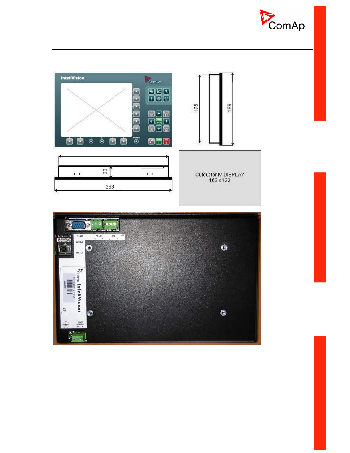
Terminal and dimensions
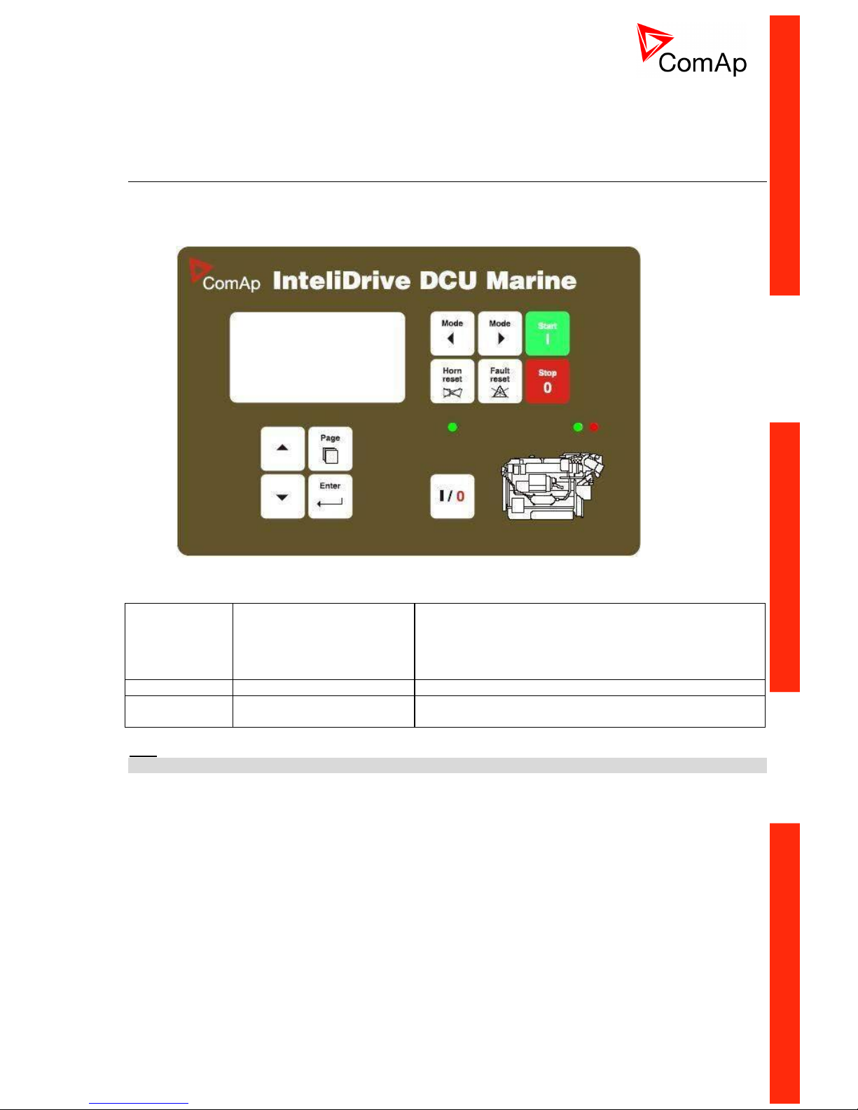
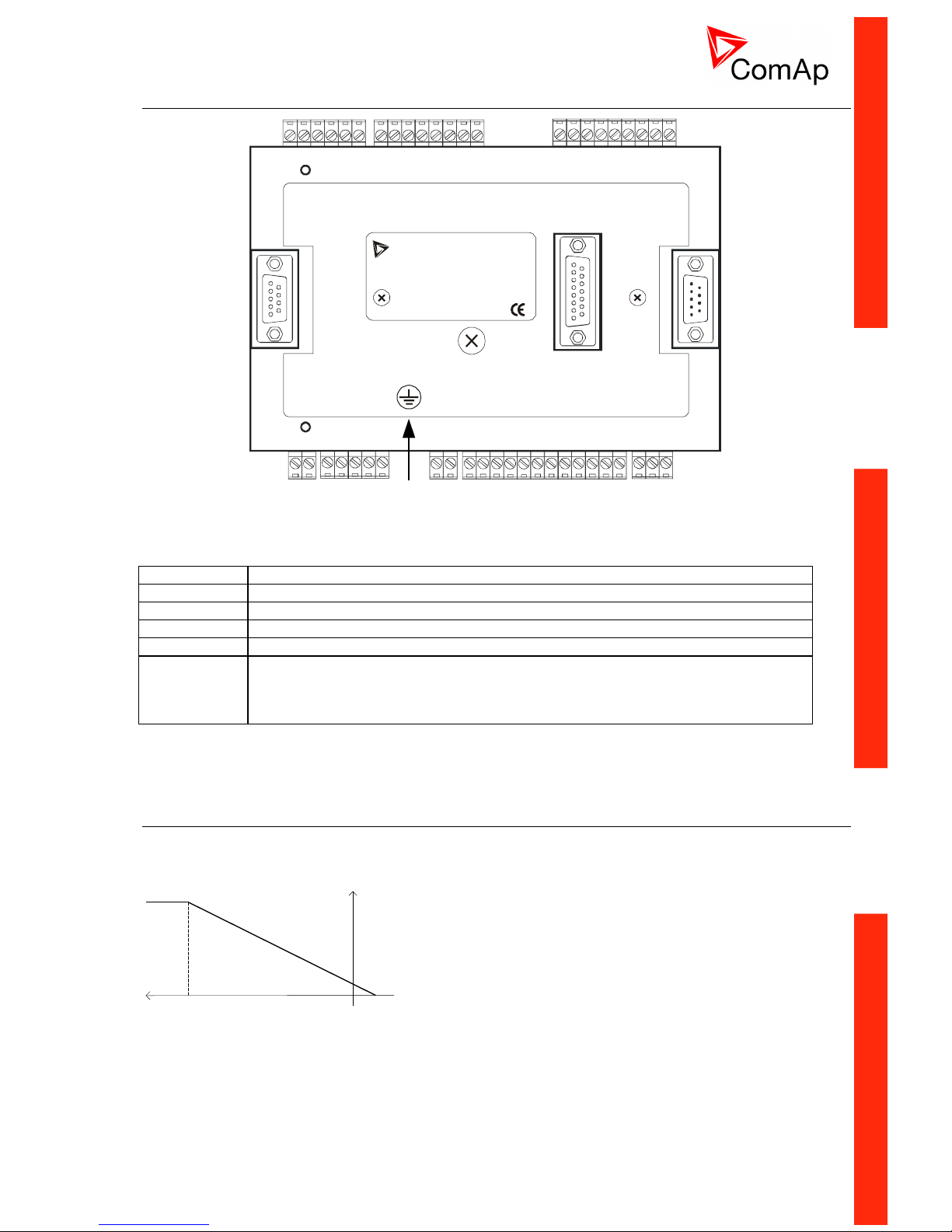
ID-DCU MARINE
The front panel of the InteliDrive controller is intended for installation in an overall enclosure – rubber seal for
IP 65 - see chapter Technical data.
Front panel LED
Right RED
Active alarm indication
Blinks when new alarm is activated.
Steady lights after “Fault reset” confirmation - when alarm
is still active.
Disappears after “Fault reset” confirmation – when alarm
is inactive.
Right GREEN
Engine running indication
Light when engine is running.
Left GREEN
Indication of Binary output
Close load state
Light when output is Closed.
Hint:
Please check the last software version.
Page 11
ID-DCU-MARINE-2.2.2, ©ComAp – June 2015 - 11 ID-DCU-MARINE-2.2.2.pdf
ID-DCU MARINE terminals
Grounding
Terminal
BOOT
JUMPER
BINARY INPUTS
RP
M
BINARY INPUTS
ANALOG
INPUTS
BINARY
OUTPUTS
POWE
R
8 - 36 V DC
EXTENSION MODULE
ID-RPU
RS 232
LB 1
EXTENSION MODULE
ID-COM
+
-
RPM GND
RPM IN
BI1
BI2
BI3
BI4
BI5
SHIELD
COM
D+
BO1
BO2
BO3
BO4
BO5
BO8
BO6
BO12
BO13
BO14
BO9
BO7
BO10
BO11
AIN1
AIN2
AIN3
AIN4
AIN6+
AIN5+
AIN8+
AIN8-
AIN6-
AIN5-
AIN7+
AIN7-
BI6
BI7
BI8
BI9
BI10
BI11
BI13
BI12
BI14
ID-DCU-Marine
RPM
Primary RPM
BI1 to BI14
Binary inputs, active when closed to minus power supply
BO1 to BO14
Binary outputs; Low side switch; 0,5 Amps each;
D+
D plus terminal
AIN1 to AIN4
Analog inputs – group 1
AIN5+, AIN5AIN6+, AIN6AIN7+, AIN7AIN8+, AIN8-
Analog inputs – group 2
ID-DCU xx -LT version with display preheating
LT is an option for extending of operating temperature range from -20 to -40 °C. Heating foil is not part of
standard ID-DCU and ID-MCU (without -LT extension).
Board temperature
+5 °C
- 40 °C
Preheating
3,5 W
The only one low temperature sensitive part is the controller
display.
ID-DCU-Industrial-LT version contains a preheating foil on the
display activated below +5°C (measured on the PCB). Heating
is switched off when controller power supply is below 10VDC
(together with display backlight).
Page 12
ID-DCU-MARINE-2.2.2, ©ComAp – June 2015 - 12 ID-DCU-MARINE-2.2.2.pdf
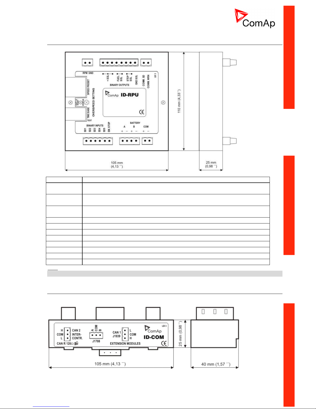
ID-RPU terminals
Redundant Protection Unit. ID-RPU is mounted directly to ID-DCU MARINE box.
RPM
Secondary RPM
+SOL
Common power supply for galvanic separated Fuel solenoid and Stop solenoid
outputs.
FUEL SOL
Fuel solenoid output, High side switch (8 Amps), BW detection in open state or above
1 amp load
STOP SOL
Stop solenoid output, High side switch (8 Amps), BW detection in open state or above
1 amp load
GND SOL
Common GND for Fuel and Stop solenoid outputs
COMM.SD
Common Shut down output, Low side switch (0,5 Amps)
COMM.WRN
Common Warning output, Low side switch (0,5 Amps)
SD1 to SD5
Shut down inputs, BW detection, Normally open
EM.STOP
Emergency stop input, Normally closed
A+, A-
Primary battery
B+, B-
Secondary battery
COM+, COM-
Battery A, B output to ID-DCU MARINE
Hint:
10 k resistor must be connected in parallel to SD1 to SD5 inputs.
ID-COM terminals
Communication interface ID-COM is mounted directly to ID-DCU MARINE box.
Page 13
ID-DCU-MARINE-2.2.2, ©ComAp – June 2015 - 13 ID-DCU-MARINE-2.2.2.pdf
CAN1
Extension modules: EMS, IS-AIN8(TC), IS-BIN16/8, IGS-PTM, IGL-RA15
CAN2
Intercontroller: I-RD-CAN-ID-DCU-MARINE, I-LB+, IG-IB, IB-NT,
others ID-DCU MARINE
ID-DCU ID-COM
INTERFACE
INTERFACE
INTERFACE
CAN1
J1939
J1587
CAN2
PROCESSOR
TTL
TTL
TTL
120 ohms
120 ohms
Hint:
Put jumper to connect the internal 120 terminating resistor for CAN2 interface.
ID-COM module is not required when inter-controller CAN2 and J1587 lines are not used. In this case
connect Extension modules CAN1 directly to Extension modules port ID-COM on ID-DCU MARINE (9-pin
connector: 5=H, 9=L).
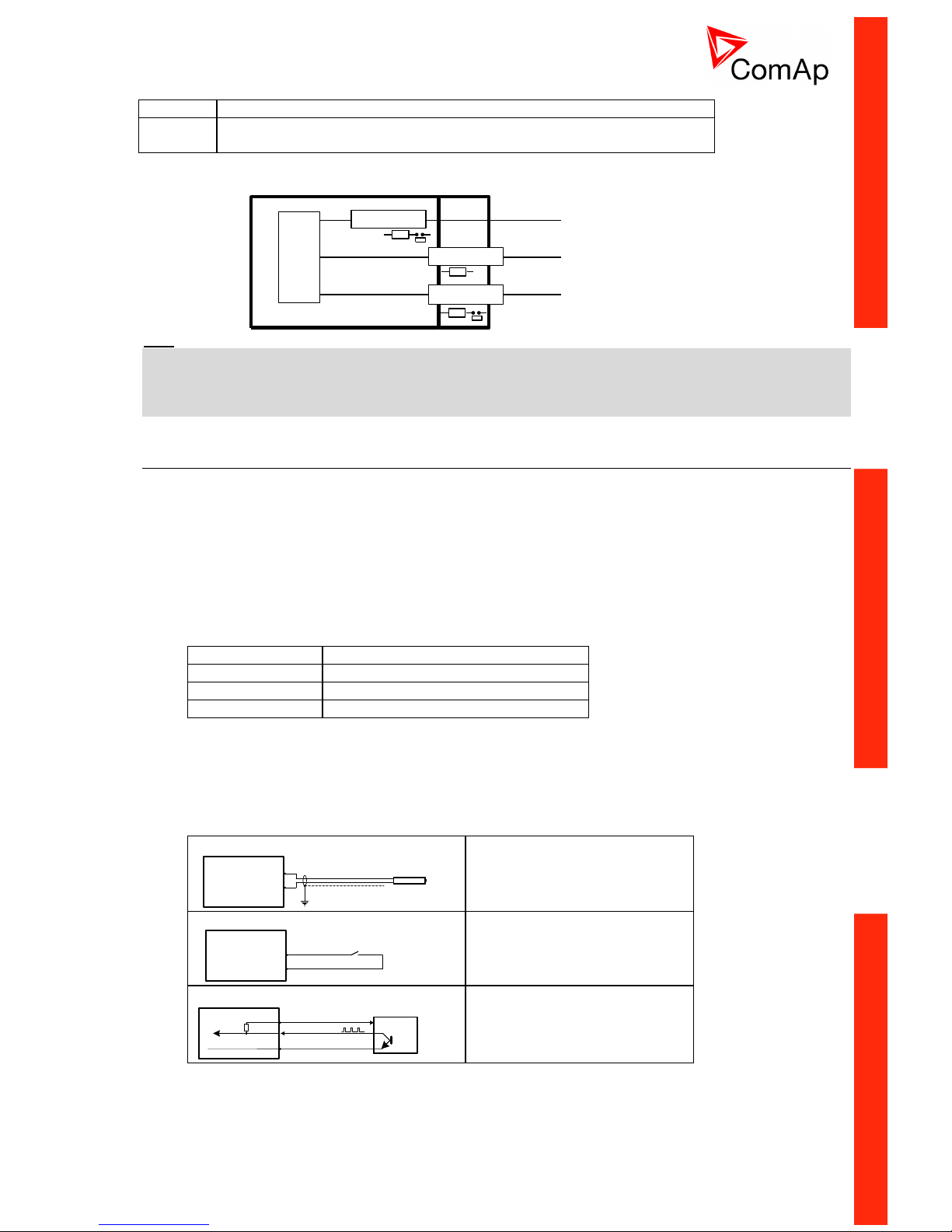
ID-SCM Speed control module
ID-SCM module is interface module for InteliDrive controller application. Module is mounted directly to IDDCU MARINE controller case. Module power supply: 8 to 36VDC.
Inputs
RPM1, RPM2: Two inputs for frequency (e.g. flow) measuring. Expected sensor is magnetic pickup – with
maximal frequency range up to 8 kHz. The output values SCM Freq1, SCM Freq2 calculation use setpoints
SCM unit: FreqRate1 and FreqRate2 - see below.
Closed jumper divides input frequency by 16 - recommended for higher frequency (>1000Hz) measuring.
Jumper position does not influence output value range.
Jumper
RPM input nominal frequency range
Closed
> 1000 Hz
Closed or Opened
500 – 1000 Hz
Opened
< 500 Hz
IMP1, IMP2: Two impulse inputs for integral (e.g. consumption) measuring. It is expected NPN – open
collector (active) impulse sensor with maximal frequency range up to 60 Hz. Minimal pulse duration is 1ms.
The output values SCM Imp1, SCM Imp2 calculation use setpoints SCM unit: TransferRate1 and
TransferRate2 - see below.
ID-SCM inputs wiring example
RPM IN
RPM GND
Magnetic pickup
RPM1, RPM2
Magnetic pickup wiring to
RPM1 and RPM2 inputs.
PWR
IN
GND
Contact
IMP1, IMP2
Contact sensor wiring to
IMP1 and IMP2 inputs.
Active NPN
sensor
+24VDC
GND
IMP1, IMP2
PWR
IN
GND
Active NPN sensor wiring to
IMP1 and IMP2 inputs.
Page 14
ID-DCU-MARINE-2.2.2, ©ComAp – June 2015 - 14 ID-DCU-MARINE-2.2.2.pdf
Outputs
AOUT1, AOUT2: Two configurable analog outputs for indication or any loop control. Outputs are jumper
adjustable between 0 to 10VDC and 0 to 20 mA.
AOUT3 - Speed governor: Configurable analog voltage interface to engine speed governor for mechanical
engines (without ECU). Output is jumper selectable between ±10VDC and ±10VDC via 10 k or PWM
(1600Hz / 5V, 10mA max).
Default jumpers setting: AOUT1 and AOUT2 ~ 0-10VDC; Speed governor ~ ±10VDC; RPM1 and
RPM2 ~ opened jumper (divides input frequency by 1).
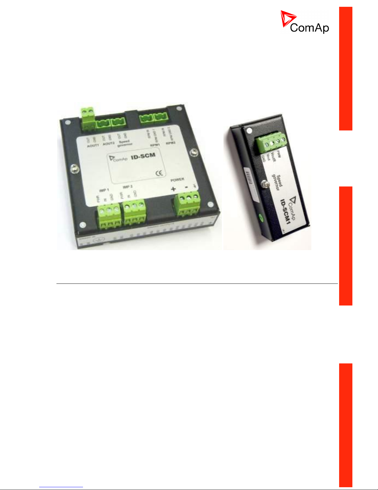
ID-SCM1
ID-SCM cost effective version with just one Speed governor output. ID-SCM1 module is one analog output
module for InteliDrive industrial or marine applications. Module is mounted directly to ID-DCU MARINE
controller case.
Technical data
Power supply: internal supply from ID-DCU MARINE (8 to 36 VDC)
Operating temperature range: -40°C to +70°C
Number of analog outputs: 1, no galvanic separation
Analog output refreshment: 100 ms
Analog output options
a) PWM 1600 Hz (fix), 5V level, max 10 mA
b) 0 to 10VDC ± 1%, 10 k output resistance
c) 0 to 10VDC ± 1%, max 5 mA (voltage output)
Configuration in DriveConfig
a) Module = SCM
b) I/O – Analog outputs – SCM - AOUT1 (only)
a. Source
b. Low convert limit
c. Hi convert limit
Page 15
ID-DCU-MARINE-2.2.2, ©ComAp – June 2015 - 15 ID-DCU-MARINE-2.2.2.pdf
InteliVision 8, InteliVision 8 Marine
Terminals and Dimension
Page 16
ID-DCU-MARINE-2.2.2, ©ComAp – June 2015 - 16 ID-DCU-MARINE-2.2.2.pdf
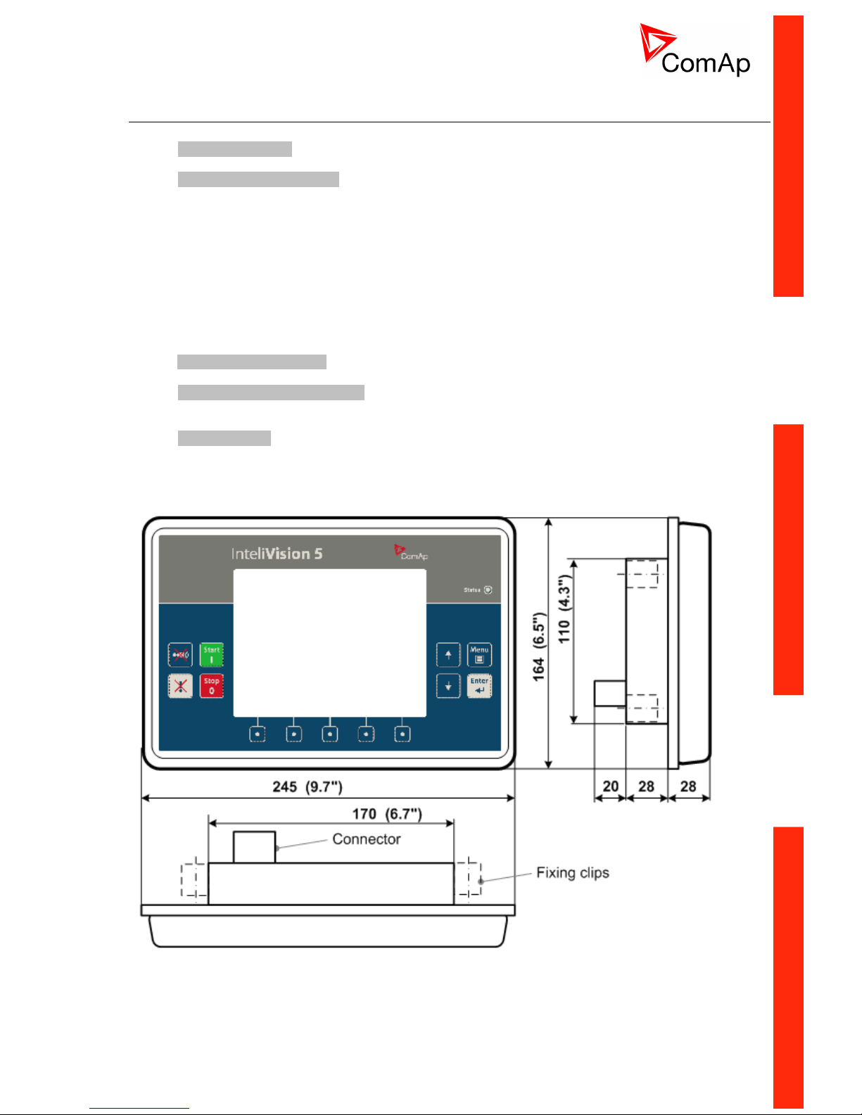
InteliVision 5 CAN, InteliVision 5 CAN Backlit
5” color display. InteliVision 5 CAN is offered in two hardware modifications:
InteliVision 5 CAN
InteliVision 5 CAN Backlit
The only HW difference between two versions is presence of standard or backlight keyboard version, i.e. if
there is present a feature of back-lighted buttons or not. Both versions are IP65 protected from all sides,
equipped with binary output switch for HORN signaling, CAN interface is galvanically separated.
The InteliVision 5 CAN version is intended to use with InteliDrive controllers only (ID-DCU, ID-DCU MARINE,
ID-Mobile, ID-Mobile Logger), Backlit version supports also InteliGen-NT and InteliSys-NT controllers.
Depending on customer preferences there can be used optional accessories:
InteliVision 5 Harness-2 - 2m prefabricated cable with unassigned wires at the end
InteliVision 5 IP 65 Connector - connector set containing connector body and 10 corresponding
terminal female pins
ECU Simulator - set containing supported USB/CAN converter and various
cabling, for new firmware / font / logo download into the
InteliVision 5 CAN
Page 17
ID-DCU-MARINE-2.2.2, ©ComAp – June 2015 - 17 ID-DCU-MARINE-2.2.2.pdf
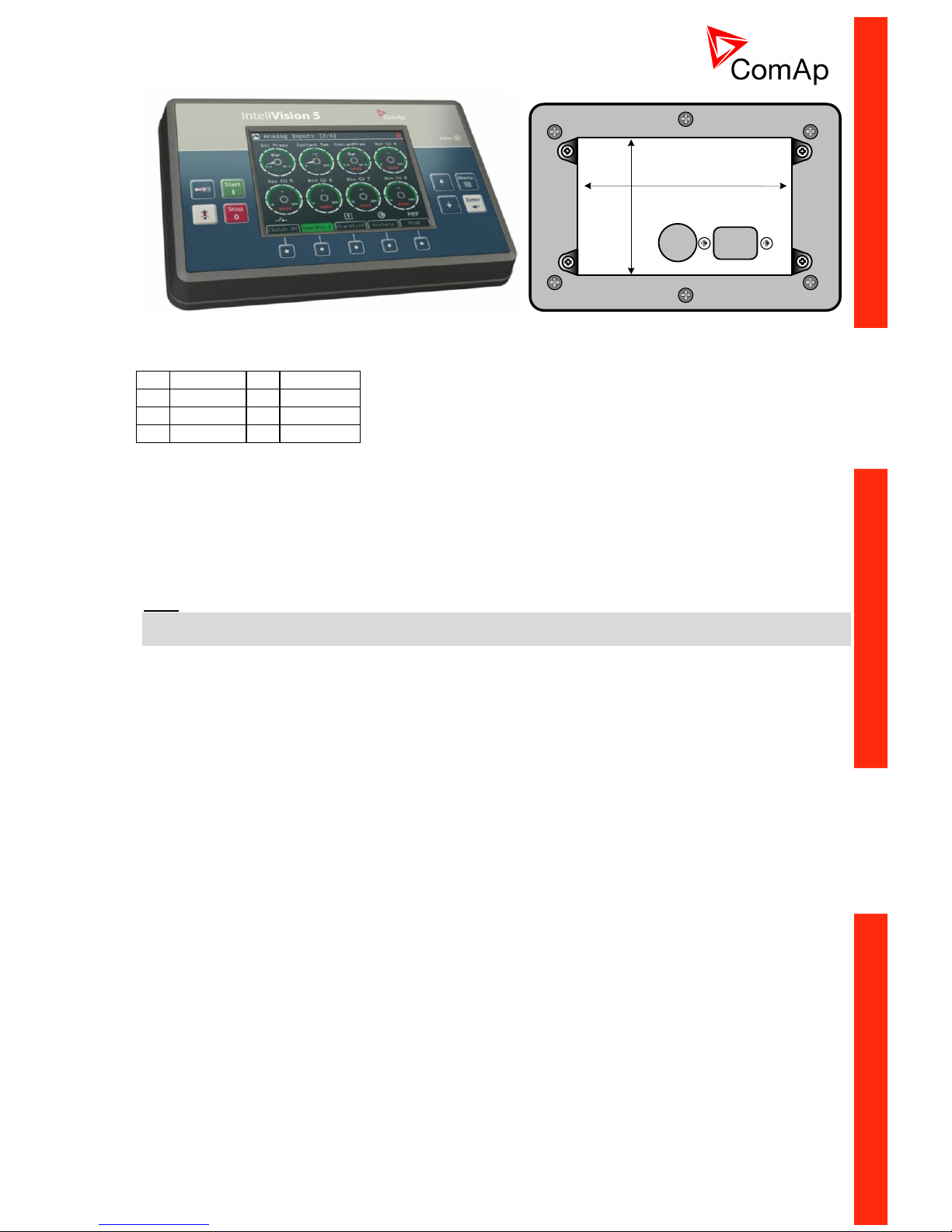
170 (6.7")
110 (4.3")
InteliVision 5 CAN connector wiring
1
GND
5
UBatt
2
A/B IN
6
CAN-L
3
BO-A
7
COM
4
BO-B
8
CAN-H
1 - 5 Power supply 8 – 36VDC
6 - 8 CAN bus (with galvanic separation)
3 - 4 Binary output configured for Horn function. It is Solid State Relay with galvanic separation. Max
36VDC/0,5A (like free contact).
2 – 1 Analog/Binary Input for display and buttons backlit control. Connect resistive pot for continuous
backlit change: 0 ~ 0%; 2400 ~ 100%. Or just place contact to switch between 0% and 100%
intensity.
Note:
It is possible to connect up to five InteliVision 5 CAN or four InteliVision 8 displays to common CAN2 bus.
The display addresses must be different in this case.
Page 18
ID-DCU-MARINE-2.2.2, ©ComAp – June 2015 - 18 ID-DCU-MARINE-2.2.2.pdf
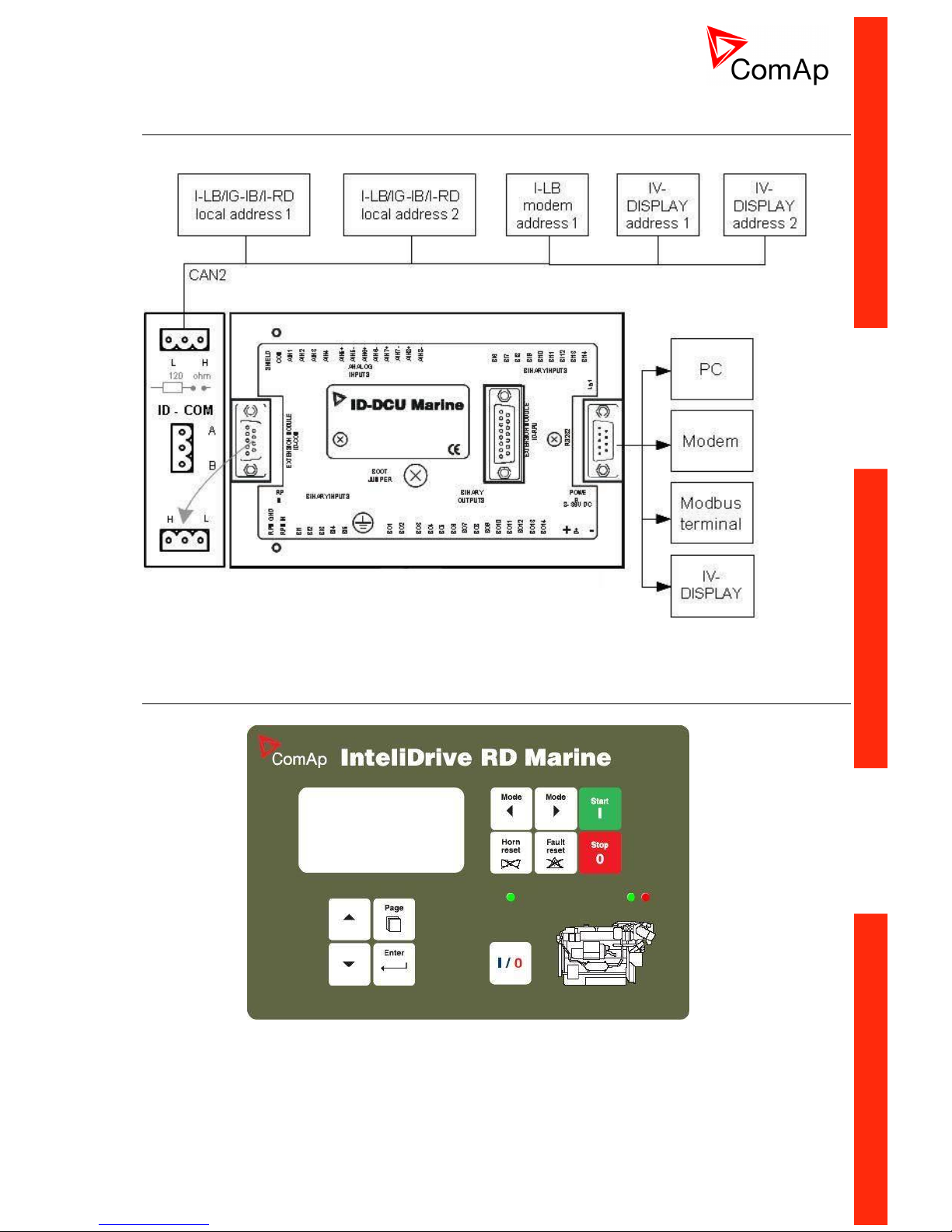
Communication lines wiring
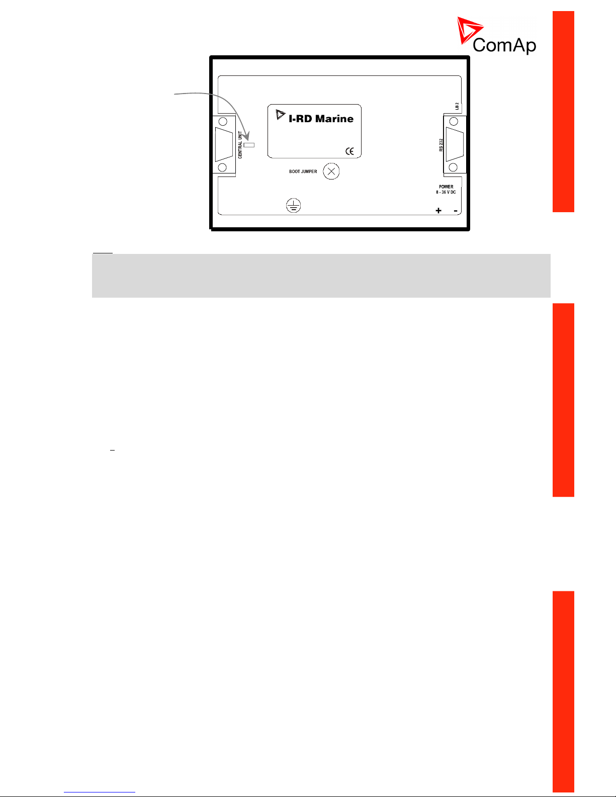
I-RD-CAN-ID-DCU-MARINE (Remote Panel)
Page 19
ID-DCU-MARINE-2.2.2, ©ComAp – June 2015 - 19 ID-DCU-MARINE-2.2.2.pdf
Hint:
The ID-DCU MARINE controller can be used as an I-RD-CAN-ID-DCU-MARINE remote display after
uploading of the I-RD-CAN-ID-DCU-MARINE firmware. The CAN1 physical interface is then used for CAN
connection to the controller (there is no need to use ID-COM module), controller’s CAN2 physical interface
has to be used on the other side of the CAN bus.
Remote Display I-RD-CAN-ID-DCU-MARINE (Remote Panel) works as “a remote control panel” for
the ID-DCU MARINE master controller.
All panel buttons works the same way as corresponding buttons on master controller. All LEDs
displays the same state as corresponding LEDs on master controller.
Start, Stop buttons and setpoint changes are not active when master ID-DCU MARINE controller is
in LOC (Local) mode.
I-RD-CAN-ID-DCU-MARINE screen listing does not influence screen on master controller.
Interruption of the serial line between master device and I-RD-CAN-ID-DCU-MARINE will have no
effect to the engine. Master device will always be able to work without connected Remote display.
I-RD-CAN-ID-DCU-MARINE displays the same screens as its master controller and can be switched
to the same languages. The user interface is identical as the master controller.
I-RD-CAN-ID-DCU-MARINE is the same mechanical and electronic design (the same box but some
electronic components were removed). No inputs and outputs are available on I-RD-CAN-ID-DCUMARINE only.
It is possible to connect I-RD-CAN-ID-DCU-MARINE to ID-DCU MARINE via RS232 (38,4kbps) or
via CAN bus (50 or 250 kBd).
I-RD-CAN-ID-DCU-MARINE automatically downloads new configuration table from master controller
if the CRC doesn’t match the CRC of the stored configuration table.
I-RD-CAN-ID-DCU-MARINE uses separate mhx firmware different from controller firmware
compatible with both ID-DCU and ID-DCU MARINE.
I-RD-CAN-ID-DCU-MARINE firmware can be reprogrammed via Boot load procedure only.
I-RD-CAN-ID-DCU-MARINE backlight can be switched to full intensity when middle power supply
terminal (D+ in DCU) is closed to + power supply.
BL
Jumper (under cover)
to connect I-RD-CANID-DCU-MARINE
internal 120Ω resistor
for CAN bus line
terminating
. .
Page 20
ID-DCU-MARINE-2.2.2, ©ComAp – June 2015 - 20 ID-DCU-MARINE-2.2.2.pdf
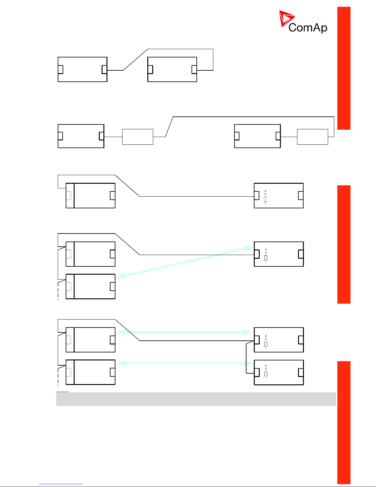
I-RD-CAN-ID-DCU-MARINE wiring
RS232 interface: three wire cable (2-3, 3-2, 5-5), max. cable length up to 10 meters.
ID-CU I-RD
RS232 RS232
Contr.addr 1
CAN addr. 1
Contr.addr 1
Using converters to RS485 or RS422 increases distance up to 1000 meters.
Recommend external converter: ADVANTECH – ADAM 4520: RS232 to RS422/485 converter, DIN rail,
automatic RS485 bus supervision, no external data flow control signals, galvanic isolated, baud rate
38400bps.
ID-CU I-RD
RS232 RS232
RS232 /
RS422/485
RS232 /
RS422/485
RS422/485
Converter Converter
Contr.addr 1
CAN addr. 1
Contr.addr 1
CAN bus connection requires ID-COM module on ID-DCU MARINE. Use I-RD-CAN-ID-DCU-MARINE
Central unit 9-pin connector (5=CAN H, 9=CAN L) to connect CAN bus. Put jumper to connect I-RD-CAN-IDDCU-MARINE internal 120 resistor for CAN bus line terminating.
ID-CU
CAN2
ID-COM
I-RD
Contr.addr 1
CAN addr. 1
Contr.addr 1
5 - CAN H
9 = CAN L
120 ohm
I-RD-CAN-ID-DCU-MARINE can monitor any ID-DCU MARINE controller on the CAN2 bus based on I-RDCAN-ID-DCU-MARINE Contr. address setting.
1.ID-CU
CAN2
ID-COM
I-RD
2.ID-CU
ID-COM
`
`
Contr.addr 1
Contr.addr 2
CAN addr. 1
Contr.addr 2
5 - CAN H
9 = CAN L
120 ohm
It is possible to connect up to five I-RD-CAN-ID-DCU-MARINE to common CAN2 bus. The I-RD-CAN-IDDCU-MARINE addresses must be different in this case.
1.ID-CU
CAN2
ID-COM
I-RD
2.ID-CU
ID-COM
I-RD
CAN addr. 1
CAN addr. 2
Contr.addr 1
Contr.addr 2
Contr.addr 1
Contr.addr 2
5 - CAN H
9 = CAN L
120 ohm120 ohm
Hint:
There is no connection between ID-DCU MARINE and Remote panel during ID-DCU MARINE controller
programming and in INIT state.
Page 21

ID-DCU-MARINE-2.2.2, ©ComAp – June 2015 - 21 ID-DCU-MARINE-2.2.2.pdf
How to establish ID-DCU MARINE to I-RD-CAN-ID-DCU-MARINE connection
Following screen appears after I-RD-CAN-ID-DCU-MARINE power supply is switched on and there is no
connection to ID-DCU MARINE established.
Screen rows
Meaning / selection range
I-RD-CAN-ID-DCU-MARINE front
panel button to change
I-RD-Industrial 1.x
I-RD-CAN-ID-DCU-MARINE firmware
branch and version
ComAp 2004
Copyright
SN: xxxxxxxx
Controller serial number
Contr. Addr: 1
Controller address: 1 to 8 and AUTO
/
Connection: CAN addr.1
Connection: CAN addr.1, CAN addr.2,
RS232
Page
NO CONNECTION
TRYING…. , PROGRAMMING
I-RD-CAN-ID-DCU-MARINE status
during Init state.
1. Connect selected communication line between ID-DCU MARINE controller and I-RD-CAN-ID-DCUMARINE panel.
2. Switch ID-DCU MARINE and I-RD-CAN-ID-DCU-MARINE power supply on.
3. After I-RD-CAN-ID-DCU-MARINE Initialization screen appears: Use front panel / buttons to
change Controller address in the range 1 to 8 or AUTO. I-RD-CAN-ID-DCU-MARINE automatically
increases the controller address and tries to open connection. This Controller address must
correspond to connected ID-DCU MARINE Basic setting: Controller address setpoint.
4. Use Page button to set I-RD-CAN-ID-DCU-MARINE connection type: CAN addr.1, CAN addr.2 or
RS232.
5. Then press Enter button to start data download. Message TRAYING … appears on the I-RD-CANID-DCU-MARINE screen. Unsuccessful attempt to read data is repeated each 15 sec.
6. The Programming bargraph appears on I-RD-CAN-ID-DCU-MARINE screen after connection is
opened.
7. Standard ID-DCU MARINE screen appears after complete configuration is loaded to I-RD-CAN-IDDCU-MARINE.
Hint:
To switch to Init screen press Page button for more than 2 sec when CFG table error message appears on
the I-RD-CAN-ID-DCU-MARINE screen.
Page 22
ID-DCU-MARINE-2.2.2, ©ComAp – June 2015 - 22 ID-DCU-MARINE-2.2.2.pdf
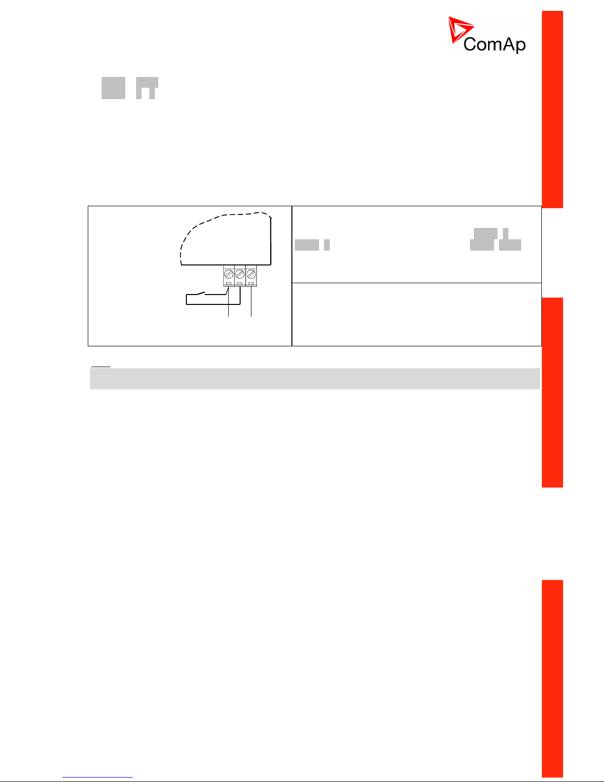
I-RD-CAN-ID-DCU-MARINE backlight-brightness intensity change
(the same procedure for ID-DCU MARINE and I-RD-CAN-ID-DCU-MARINE)
1. Enter + Page buttons = switch to Info screen and then
2. Enter + / button increases/decreases the display backlight (it is stored - until the next change).
3. The setpoint Basic setting: LightTimeOff in I-RD-CAN-ID-DCU-MARINE works locally for I-RD-CAN-IDDCU-MARINE (this is only exception) and it is not transferred to the central unit. Backlight is after this time
switched off from current level. Any key touch activates the backlight.
That means it is possible to set I-RD-CAN-ID-DCU-MARINE backlight level and LightTimeOff independently
to ID-DCU MARINE.
From I-RD firmware version 1.2 and hardware version 2.0 from s.n. xxxx0006 it is possible to change
Remote panel display backlight between adjustable and full level via external switch – see drawing below.
POWER
8-36VDC
+ -
POWER
SUPPLY
BACKLITE
SWITCH
REMOTE PANEL
Opened switch = Backlight is adjustable by Enter+ /
Enter+ panel buttons from INFO screen (Enter+Page)
Closed switch = full backlight like in ID-DCU MARINE
Hint:
It is not possible to control I-RD-CAN-ID-DCU-MARINE backlight continuously via analog input like on IDDCU MARINE.
BL
Page 23
ID-DCU-MARINE-2.2.2, ©ComAp – June 2015 - 23 ID-DCU-MARINE-2.2.2.pdf
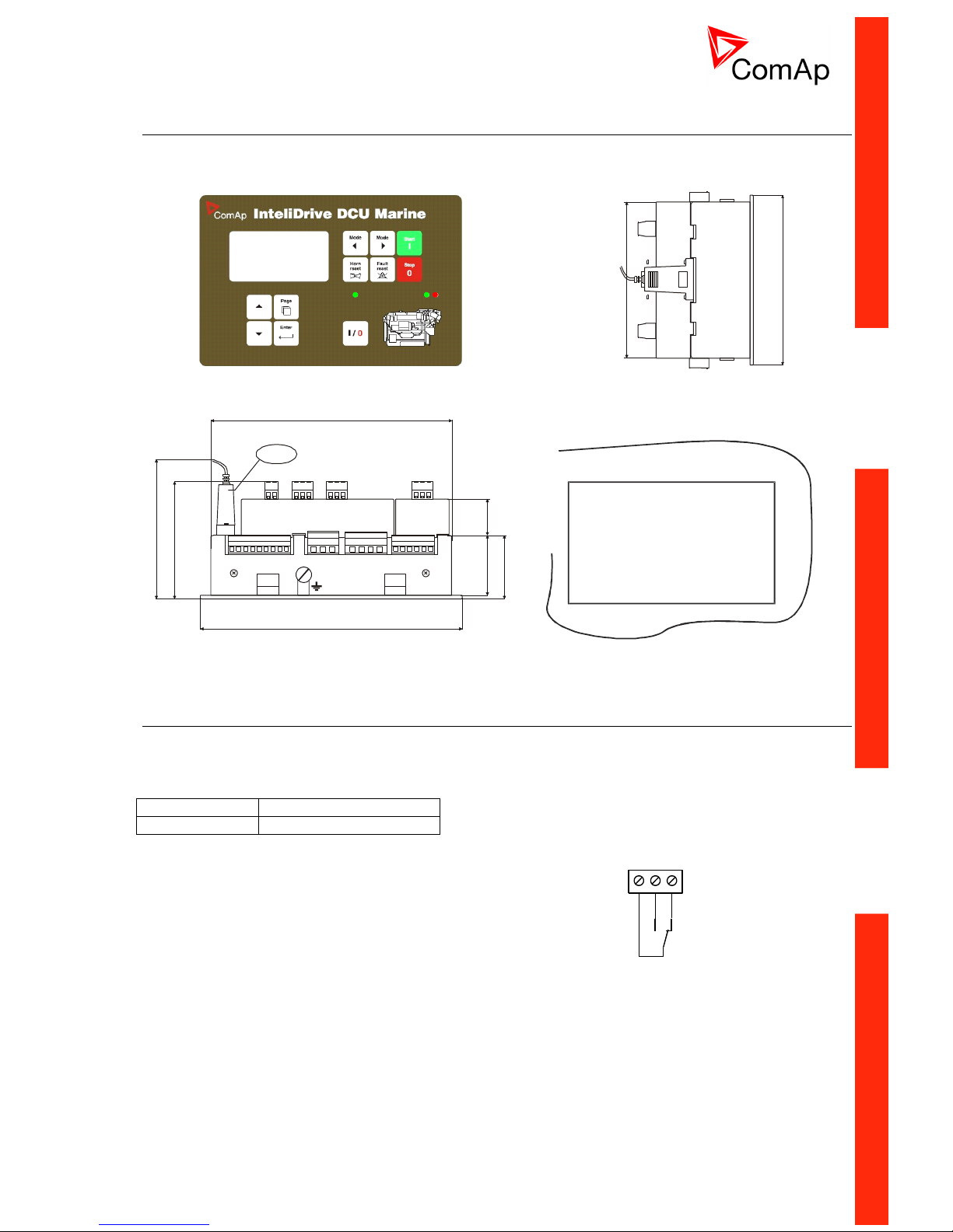
ID DCU MARINE dimensions
ID-COM and ID-SCM are mounted directly to ID-DCU MARINE case.
I-RD-CAN-ID-DCU-MARINE (Slave panel) has the same dimensions.
ID-RPU
ID-CU
ID-COM
183 (7,2")
80(3,1")
42,5(1,7")
24
(0,9")
47(1,8")
~ 110(4,3")
170 (8,87")
RS232
123(4,8")
110(4,4")
Cutout
for InteliDrive
113 x 175 mm
(4.4 x 6,9“)
ID-DCU MARINE box is fixed using four screw clips.
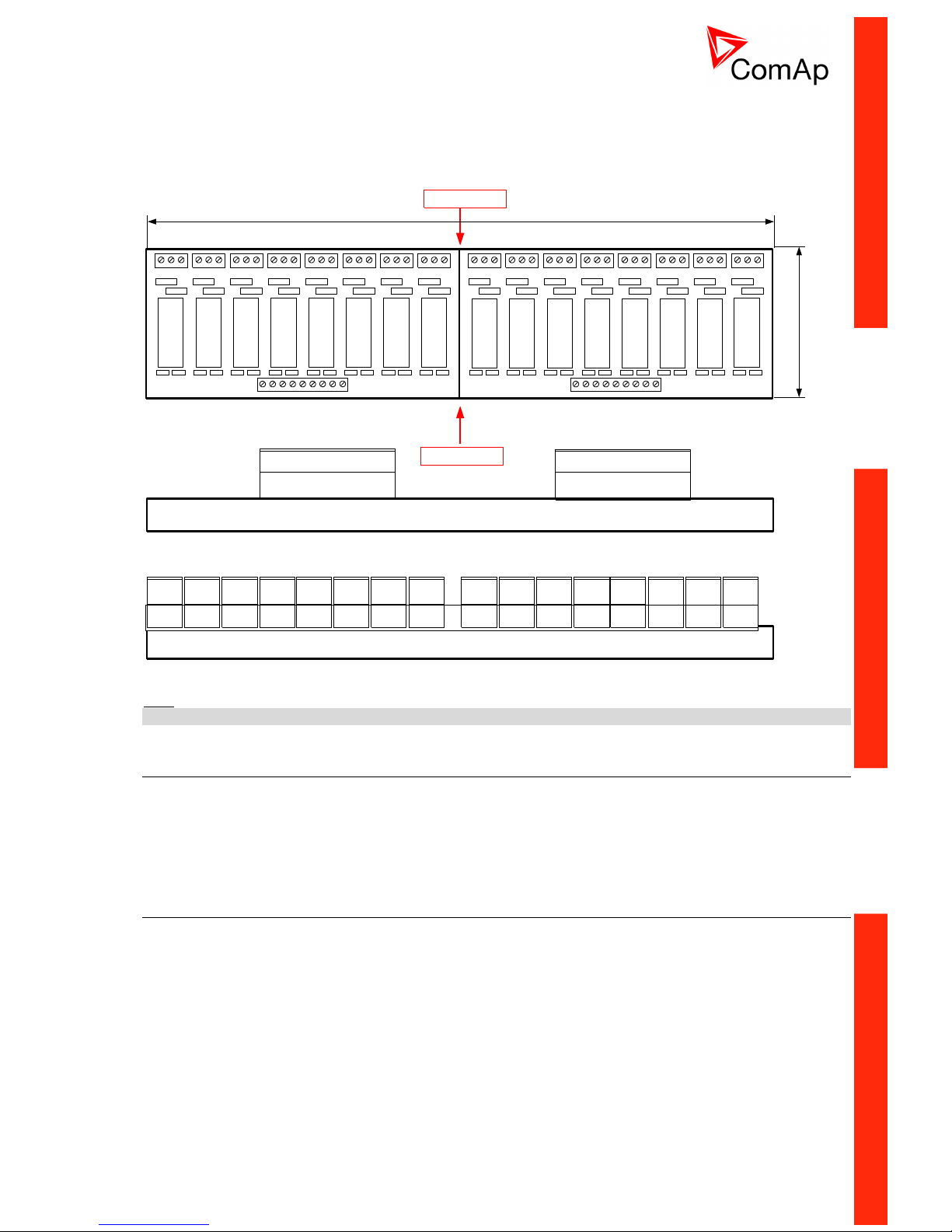
I-RB8/16 technical description
Relay board contains 16 or 8 relays for ID-DCU MARINE binary (open collector) output separation. All relays
are placed in sockets.
Product options
I-RB16
16 relays, load 24 VDC
I-RB8
8 relays, load 24 VDC
Number relays: 16 or 8 in sockets
Nominal voltage: 24 VDC
Voltage range: 16,8 – 36 VDC
Relay opens at: 10% of nominal voltage
Electric / mechanic cycles: 100 000 / 10 000 000
Operating temperature range: - 40°C to 70°C
Maximal load: 6 A resistive load at 24VDC
4 A inductive load at 24 VDC
Contacts protection: varistor 14DK390 between 1-2 and 1-3
1K2 3
1-2 n.o.
1-3 n.c.
Page 24
ID-DCU-MARINE-2.2.2, ©ComAp – June 2015 - 24 ID-DCU-MARINE-2.2.2.pdf
Mechanical dimension
I-RB16 is 35 mm DIN rail mounted. One unit contains two parts (separate PCB) 8 relays each on common
plastic base.
I-RB16, I-RB8 is 60mm high from DIN rail base.
16
X17
11 1 11 1 11
1 +
X18
11 1 11 1 11
RE1
RE2
RE3
ER4
RE5
RE6
RE7
RE8
RE9
RE10
RE11
ER12
RE13
RE14
RE15
RE16
X3X1X2X6 X4X5X8 X7X11 X9X10X14 X12X13X16 X15
9 +
8
16 X18 9 +
View B
X18
8 X17 1 +
View B
3 X1 1
X1 X2 X3 X4 X5 X6 X7 X8 X9 X10 X11 X12 X13 X14 X15 X16
View A
3 X2 1 3 X3 1 3 X4 1 3 X5 1 3 X6 1 3 X7 1 3 X8 1 3 X9 1 3 X10 1 3 X11 1 3 X12 1 3 X13 1 3 X14 1 3 X15 1 3 X16 1
View A
300
95
X17
Hint:
I-RB16 contains two separate boards, 8 relay each.
ECU
Electronic Control Unit (fuel injection unit) is kind of extension module connected to CAN1 bus and
communicating via J1939 protocol. Generally can read up to 16 binary and analog values from engine
(inputs) and transmit up to 16 binary outputs (e.g. Start, Stop commands) and four Analog outputs (e.g.
Speed request). ECU Size = Large is extended version of electronic control unit containing doubled number
of inputs / outputs in respect of Standard ECU.
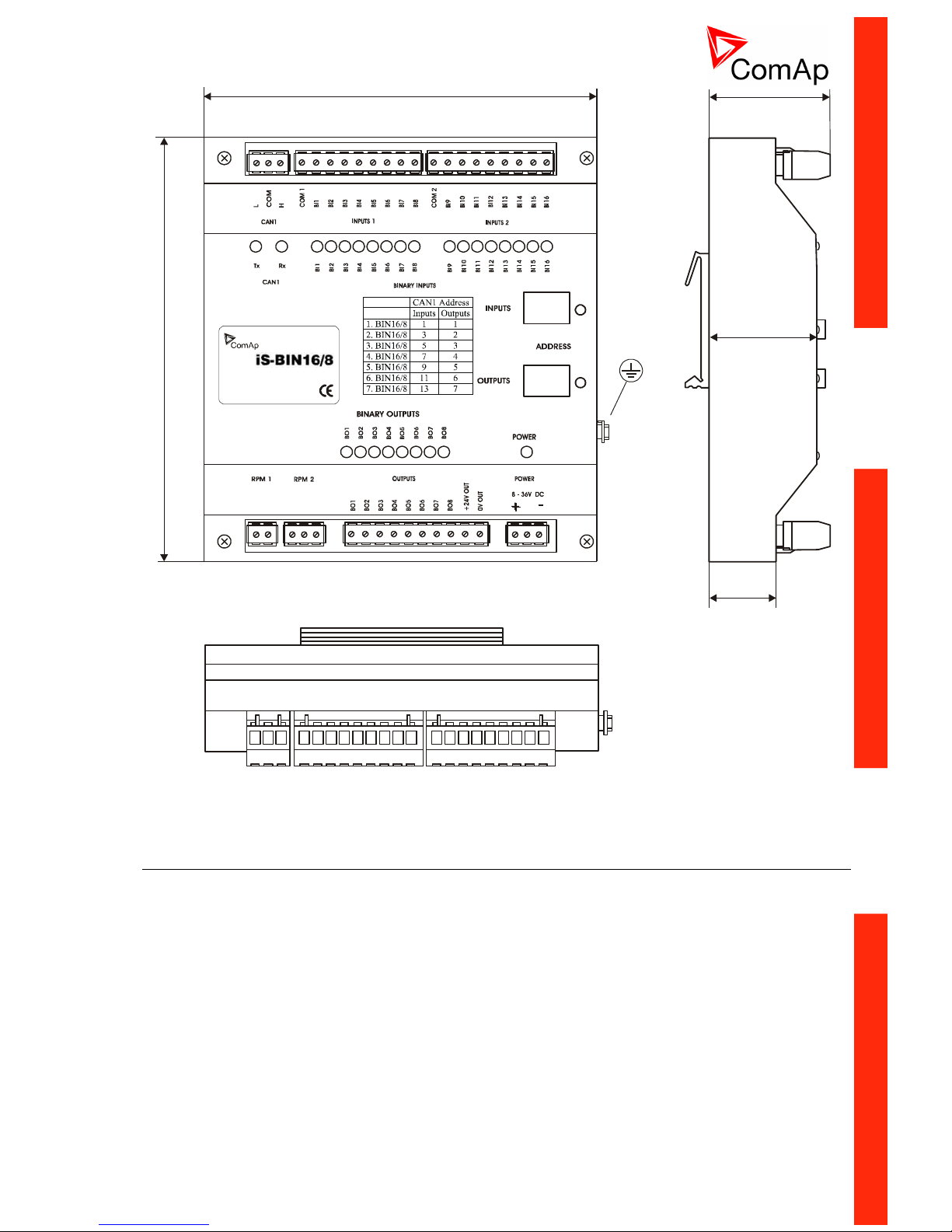
IS-BIN16/8
Extension module with 16 binary inputs and 8 binary outputs. All I/O can be configured to any logical function
or protection - see chapter Binary inputs and Binary outputs. RPM1 and RPM2 inputs are not supported in
InteliDrive.
IS-BIN16/8 module is connected on InteliDrive CAN1 bus. The corresponding module Address must be set
on module and in controller configuration. Communication fail is indicated in controller Alarm list and by
binary outputs Comm BIN fail, Comm BOUT fail. Use DriveConfig PC tool for controller configuration.
The Binary I/O specification see in chapter Technical data.
Page 25
ID-DCU-MARINE-2.2.2, ©ComAp – June 2015 - 25 ID-DCU-MARINE-2.2.2.pdf
45 (1,8")
146 (5,7")
160 (6,3")
40 (1,6")
25 (1,0")
IN1 -
RPM +
IN 2
IN1 +
RPM -
IS-BIN16/8 unit is DIN rail mount (35mm)
Inteli IO8/8
“Inteli IO8/8” is the name of the module, but it is possible to configure the module (by internal switch) to two
configurations:
1. Inteli IO8/8 (8 binary inputs, 8 binary outputs and 2 analog outputs)
2. Inteli IO16/0 (16 binary inputs, 0 binary outputs and 2 analog outputs)
Default configuration of module:
In case that the software of the controller doesn’t support this module (it is the ID-DCU Marine 2.2 case), you
can add this module to the configuration as standard BIN / BOUT / AOUT extensions (as group of 8 signals).
In this case you cannot define the type of Inputs / Outputs, all Inputs / Outputs are configured as:
Binary inputs – pull up
Binary outputs – Low side
Analog output – current, range 0-20mA
Page 26

ID-DCU-MARINE-2.2.2, ©ComAp – June 2015 - 26 ID-DCU-MARINE-2.2.2.pdf
AGND
POWER
Inteli IO8/8
Analog output
+ -
AOUT
Inteli IO8/8 0-20 mA Analog output
Terminator for analog output has special analog ground (AGND), which must not be connected to the GND.
Limit of analog ground (AGND) is 100mA.
Page 27
ID-DCU-MARINE-2.2.2, ©ComAp – June 2015 - 27 ID-DCU-MARINE-2.2.2.pdf
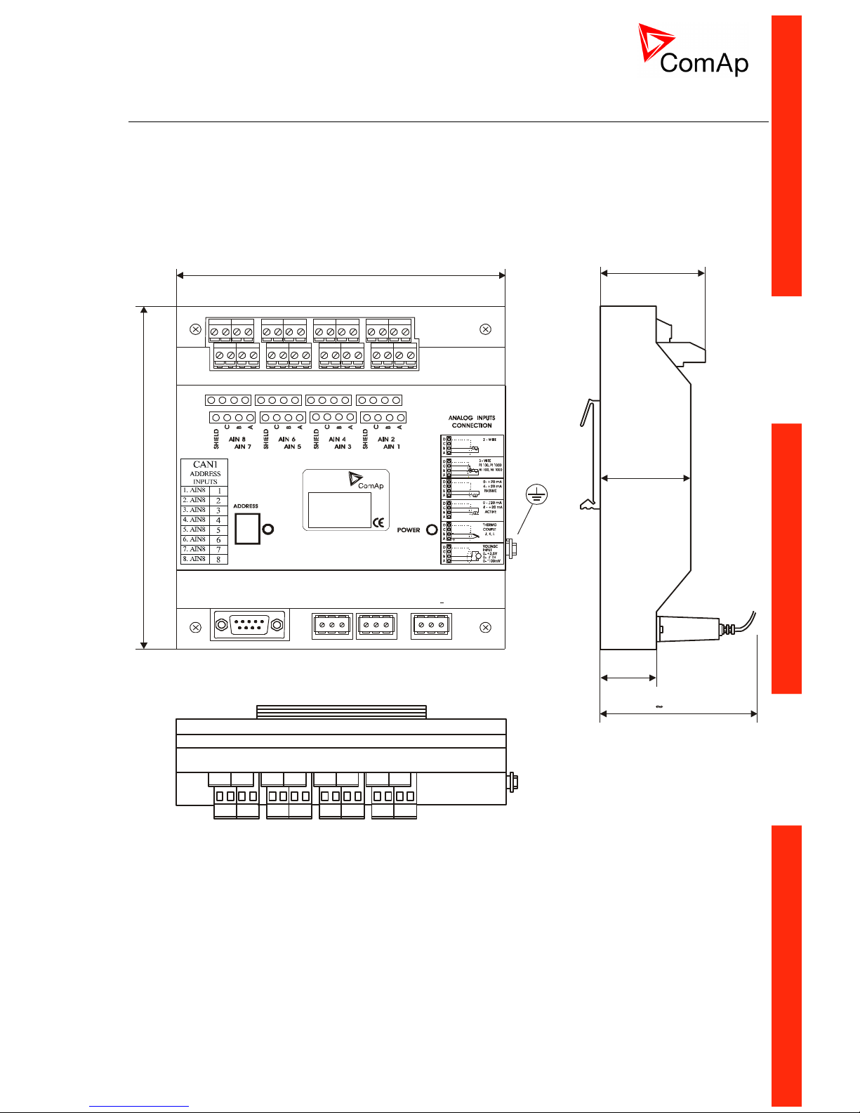
IS-AIN8
Extension module with 8 analog inputs. All inputs can be configured to any logical function or protection - see
chapter Analog inputs.
IS-AIN8 module is connected on InteliDrive CAN1 bus. The corresponding module Address must be set on
module and in controller configuration. Communication fail is indicated in controller Alarm list and by binary
output Comm AIN fail. Use DriveConfig PC tool for controller configuration.
The analog inputs specification see in chapter Technical data.
46,4 (18,3")
40 (15,7")
25 (9,8")
70 (27,5")
146 (57,5")
160 (63")
POWER
8 - 36V DC
COM
COM
CAN
CAN
RS 232
H
H
L
L
+
iS-AIN8
IS-AIN8 unit is DIN rail mount (35mm)
Page 28
ID-DCU-MARINE-2.2.2, ©ComAp – June 2015 - 28 ID-DCU-MARINE-2.2.2.pdf
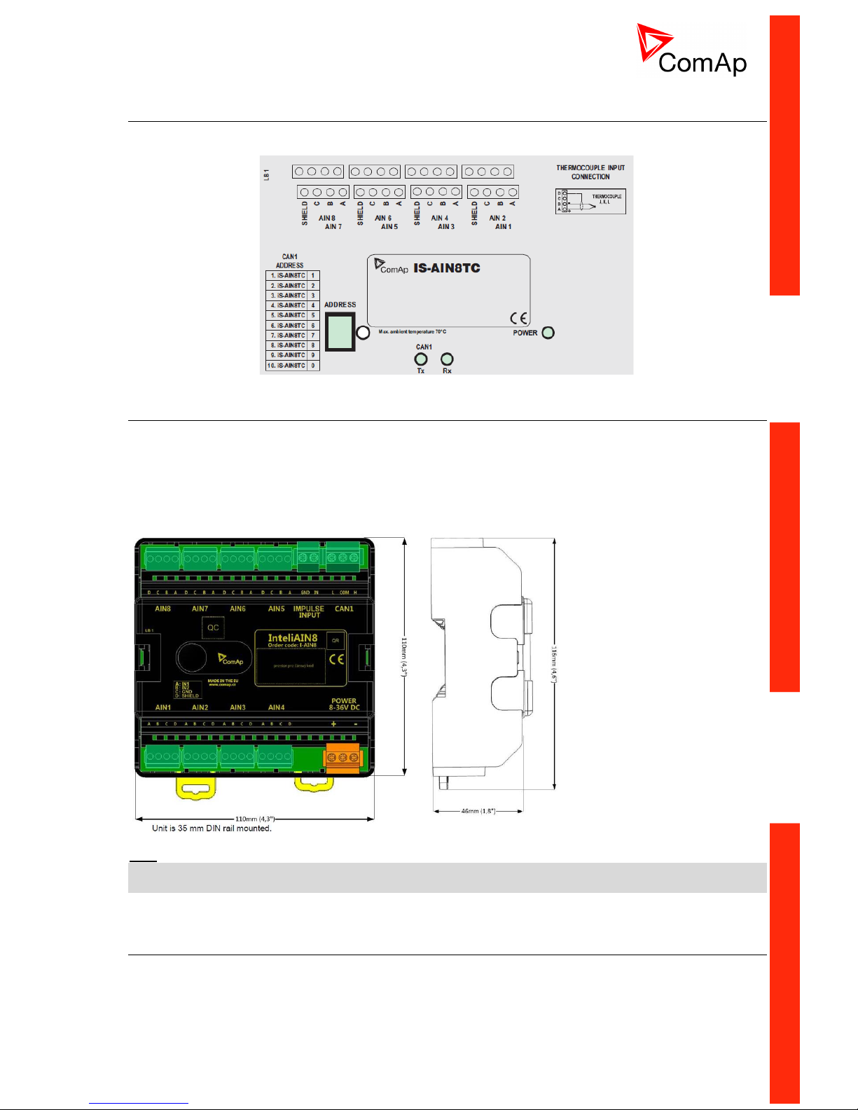
IS-AIN8TC
Extension module with 8 thermocouple analog inputs, i.e. it is simplified IS-AIN8 module with the same
dimensions. Thermocouple types J, K, L are supported.
Inteli AIN8
Inteli AIN8 module is extension module equipped with analog inputs and impulse input, however the impulse
input is not supported by InteliDrive-DCU Marine.
8 channels of Analog inputs can be configured as:
resistor three wire input
current input
voltage input
Hint:
See more details in separate document IGS-NT & ID-DCU Accessory Modules, the document is available for
download on ComAp web pages.
Inteli AIN8TC
Inteli AIN8TC module is extension module equipped with 8 analog inputs dedicated for thermocouple
sensors only.
Page 29
ID-DCU-MARINE-2.2.2, ©ComAp – June 2015 - 29 ID-DCU-MARINE-2.2.2.pdf
Hint:
See more details in separate document IGS-NT & ID-DCU Accessory Modules, the document is available for
download on ComAp web pages.
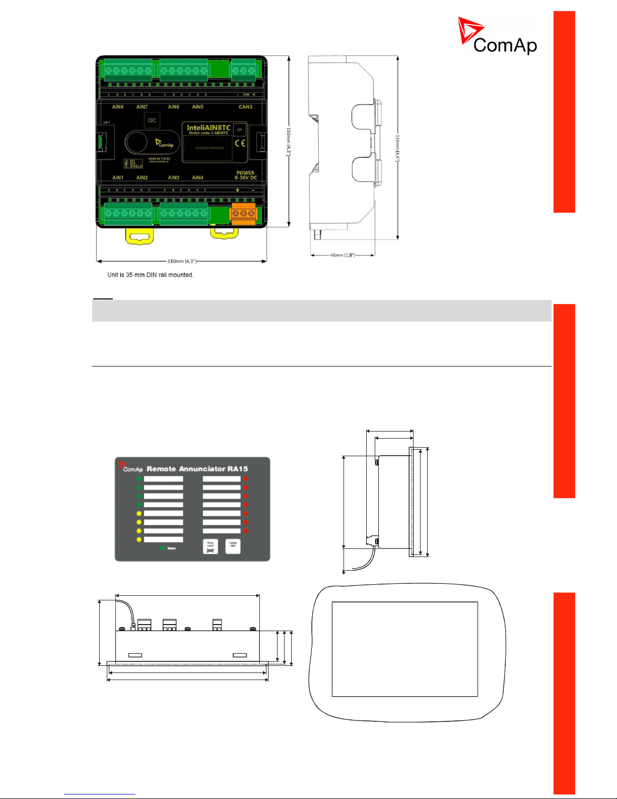
IGL-RA15 Remote annunciator
Remote (CAN1 bus, up to 200 meters) 15 LEDs states indicator. One iGL-RA15 unit can be connected to IDDCU MARINE via CAN1 as Binary output group of addresses 5 and 6. Detail descriptions see in IGLRA15.pdf user guide.
Communication fail is indicated in controller Alarm list and by binary outputs Comm BOUT fail. Use
DriveConfig PC tool for controller configuration.
165 (6,5”)
38 (1,5”)
40 (1,6”)
~ 75 (3,0”)
~ 35 (1,4”)
180 (7,1”)
185 (7,3”)
106 (4,2”)
44 (1,7”)
54 (2,1”)
~ 25 (1,0”)
120 (4,7”)
125 (4,9”)
Cutout
for Remote Annunciator
167 x 108 mm
(6,6 x 4,3)”
Page 30
ID-DCU-MARINE-2.2.2, ©ComAp – June 2015 - 30 ID-DCU-MARINE-2.2.2.pdf
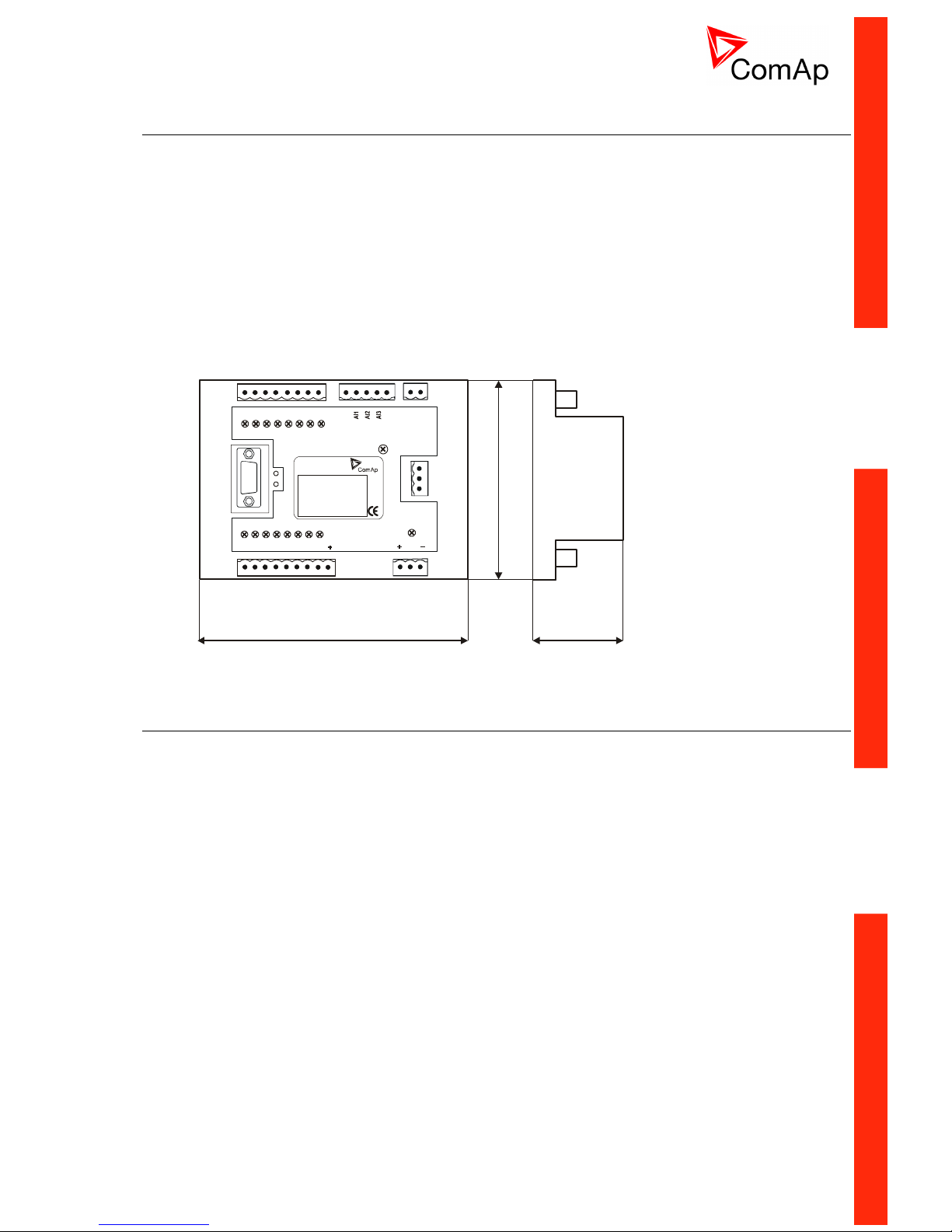
IGS-PTM
Extension module with 4 analog inputs, 8 Binary I/O. All I/O can be configured to any logical function or
protection - see chapter Binary inputs, Binary outputs and Analog inputs.
IGS-PTM module is connected on InteliDrive CAN1 bus. The corresponding module Address (1 to 4) must
be set on module and in controller configuration. Communication fail is indicated in controller Alarm list and
by binary output CommBIN fail, CommBOUT fail, CommAIN fail. Use DriveConfig PC tool for controller
configuration.
Any analog input can be configured for range:
0 – 250 (suitable for Pt100, Ni100),
0 – 100 mV (suitable for thermocouples),
0 – 20 mA.
Detail description see in IGS-PTM-1.0.pdf manual.
95 mm
(3,7´´)
43 mm
(1,7´´)
96 mm (3,8´´)
COMPENSATION
GND
POWER
8-36V DC
BINARY OUTPUTS
BINARY INPUTS
ANALOG INPUTS
AI4
BI8
BI7
BI6
BI5
BI4
BI3
BI2
BI1
0-20 mA
ANALOG OUT
BO8
BO1
BO2
BO3
BO4
BO5
BO6
BO7
CAN
RxTx
CAN
L
H
COM
LB 4
AO-
AO+
iGS-PTM
IGS-PTM unit is DIN rail (35mm) mounted.
I-AOUT8
Extension module with 8 analog outputs. All outputs can be configured to any logical function - see chapter
Analog outputs.
I-AOUT8 module is connected on InteliDrive CAN1 bus. The corresponding module Address 1 to 4 (default
1) must be set on module (by Adr.1 and Adr.2 jumpers) and in controller configuration. Communication fail is
indicated in controller Alarm list and by binary output Comm AOUT fail. Use DriveConfig PC tool for
controller configuration.
Each analog output can be switched by jumper for.
- 0 to 20 mA (default)
- 0 to 10 VDC
- Pwm (Pulse Width Modulation on 1,2 kHz)
Module is 35 mm DIN rail mounted. CAN1 terminating 120 resistor jumper is connected in default. AGND
terminals are on the same potential.
Page 31

ID-DCU-MARINE-2.2.2, ©ComAp – June 2015 - 31 ID-DCU-MARINE-2.2.2.pdf
95 mm
(3,7´)
43 mm
(1,7´)
96 mm (3,8')
Power
supply
I-AOUT8
ComAp
HW:
SW:
+ 8-36 VDC
GND
AGND
AOUT5
AGND
AOUT6
AGND
AOUT7
AGND
AOUT8
ANALOG OUTPUTS
AOUT1
AGND
AOUT2
AGND
AOUT3
AGND
AOUT4
AGND
ANALOG OUTPUTS
CANL
CCOM
CANH
CAN
U - I - p
U - I - p
U - I - p
U - I - p
p - I - U
p - I - U
p - I - U
p - I - U
1 2 Pwr
120 ohm
Functions
Number of analog
outputs
8, no galvanic separation
Type of analog outputs
(jumper selectable)
U
I
p
0 to 10VDC ± 1% , max 5 mA
0 to 20 mA ± 1% , max 500 - default
pwm 1200 Hz, 5V level, max 10 mA
Power supply
8 to 36 VDC
Current consumption
100 ÷ 300 mA at 24 VDC
Communication interface
CAN1, with jumper selectable address 1 to 4
Jumper selectable terminating resistor 120 .
RS232 interface
TTL, firmware upgrade via AT-link.
Operating temperature
range
-40°C to +70°C
Analog outputs
refreshment
Max. 300 ms
CAN address jumper setting
Up to four modules can be connected to one controller. Set module CAN address corresponding to
configuration according table below.
CAN Address
Jumper 1
Jumper 2
1
No
No
2
Yes
No 3 No
Yes 4 Yes
Yes
Page 32

ID-DCU-MARINE-2.2.2, ©ComAp – June 2015 - 32 ID-DCU-MARINE-2.2.2.pdf
Analog output hardware modification
Follow the p-I-I-U symbols on the module sticker. There are two equivalent positions for mA measuring.
AOUT
jumper
Symbol
Function
p
Pwm
Puls-With-Modulation
I
0 to 20 mA
U
0 to 10 VDC
LED indication
Green LED is located near the power supply connector.
I-AOUT8 module state
LED Pwr
No power supply
Dark
Memory fail
Fast blink (100/100 ms)
Communication fail
Slow blink (300/300 ms)
OK
Continuous light
Wiring and jumper setting example
Voltage output
0 to 10 VDC
Current output
0 to 20 mA
Current output
0 to 20 mA
Pwm output
5V, max 10 mA
AGND
AOUT
AGND
AOUT
max 500ohm
+
+
+
max 5 mA
+
AGND
AOUT
max 500ohm
AGND
AOUT
Pwm output
1200 Hz
Current output
0 to 20 mA
Current output
0 to 20 mA
Voltage output
0 to 10 VDC
Hint:
Extension module communication fail can be configured in DriveConfig to No protection, Warning,
Shutdown.
Page 33

ID-DCU-MARINE-2.2.2, ©ComAp – June 2015 - 33 ID-DCU-MARINE-2.2.2.pdf
I-LB+ Communication Bridge
I-LB+ is communication modules for communication with all devices connected to CAN2 bus. I-LB+ is
successors of the IG-MU unit designed to be used with ComAp controllers. It therefore provides additional
communication port and higher communication speed. Speed for direct/modem connection can be up to
57600 bps (IG-MU only 19200 bps). I-LB+ can be connected with PC via USB, RS232 or RS485.
For more details see Accessory Modules for IG-NT, IS-NT and ID-DCU document on ComAp web pages
http://www.comap.cz/.
IG-IB Internet bridge
Internet interface unit for single or multiple engines.
95 mm
(3,7´´)
43 mm
(1,7´´)
96 mm (3,8´´)
It is recommended to use IG-IB firmware version 2.0
IG-IB unit is DIN 35 mm rail mounted.
InternetBridge-NT
InternetBridge-NT is a communication module that allows connection of a single controller as well as whole
site to the Internet or Local area network. The connection to the Internet can be via built-in cellular modem
supporting 2G and 3G networks or Ethernet cable.
Hint:
Just CAN2 connection between InteliDrive DCU Marine and InternetBridge-NT device is possible. RS485 as
well as RS232 InternetBridge-NT interface cannot be used for interconnection with InteliDrive DCU Marine
controllers.
Page 34

ID-DCU-MARINE-2.2.2, ©ComAp – June 2015 - 34 ID-DCU-MARINE-2.2.2.pdf
I-CB communication bridge
I-CB (Communication bridge) is programmable CAN1 bus interface between InteliDrive and Engine Control
Units (like MTU, CAT etc.) without standard J1939 communication protocol. Engine values from ECU (RPM,
Oil pressure and other) are converted to standard InteliDrive I/O protocol.
Use ICBEdit software for I-CB configuration.
POWER
8-36V DC
COM
RS 232
LB 4
i-CB
95 mm
(3,7´´)
43 mm
(1,7´´)
96 mm (3,8´´)
Page 35

ID-DCU-MARINE-2.2.2, ©ComAp – June 2015 - 35 ID-DCU-MARINE-2.2.2.pdf
Recommended wiring
ID-RPU wiring
14
BATT A BATT B
+ +
-
-
+24VDC
0VDC
Max 8 A
Max 8 A
2
2
n.o.
n.c.
+
-
K17 K18
I-RB16
9 9
1 2
3
16x
K1-K16
5x10kohm
Hint:
BW protection of the ID-RPU outputs Fuel solenoid and Stop solenoid is active in open state only.
To avoid BW detection configure not wired inputs or outputs of ID-RPU as Not used by DriveConfig sw.
Battery minus terminals are separated.
See also Recommended wiring according DNV rules.
Page 36

ID-DCU-MARINE-2.2.2, ©ComAp – June 2015 - 36 ID-DCU-MARINE-2.2.2.pdf
Wiring example - Complete system without RPU
14
L H
H
-
A
B
1
2
3
4
5
6
7
8
H
L
A
B
CAN2
CAN1
ID-COM
+
L
J1587
J1939
K17 K18
I-RB16
9 9
1 2
3
16x
K1-K16
120 ohm
120 ohm
CAN2
59H
L
IS-BIN
L H
IS-AIN
L H
IGS-PTM
L H
120 ohm
+
-
POWER
+
-
POWER
+
-
POWER
120 ohm
IG-IB
IG-MU
+
-
POWER
+
-
POWER
L HL H
120 ohm
Page 37

ID-DCU-MARINE-2.2.2, ©ComAp – June 2015 - 37 ID-DCU-MARINE-2.2.2.pdf
Electronic engine without redundancy line
14
-
1
2
3
4
5
6
7
8
H
L
A
B
+
J1939
K17 K18
I-RB16
9 9
1 2
3
16x
K1-K16
120 ohm
CAN1
59H
L
IS-BIN
L H
IS-AIN
L H
IGS-PTM
L H
120 ohm
+
-
POWER
+
-
POWER
+
-
POWER
120 ohm
Engine without ECU (mechanical engine)
14
K17 K18
I-RB16
9 9
1 2
3
16x
K1-K16
120 ohm
CAN1
59H
L
IS-BIN
L H
IS-AIN
L H
IGS-PTM
L H
120 ohm
+
-
POWER
+
-
POWER
+
-
POWER
120 ohm
-
+
Page 38

ID-DCU-MARINE-2.2.2, ©ComAp – June 2015 - 38 ID-DCU-MARINE-2.2.2.pdf
Bus/Communication architecture
RS232
One of following possibilities is available:
PC software interface (DriveConfig, InteliMonitor).
Modbus protocol option for SCADA systems.
Analog or GSM Modem interface.
IG-IB – internet interface.
CAN1 / J1939 / KWP2000
CAN1 is data line for controller Inputs/Outputs extension. It is possible to connect following extension
modules:
ECU (Engine Control Unit),
IGS-PTM (8 BI, 8BO, 4AI, 1AO),
IS-AIN8 (8AI),
IS-AIN8TC (8AI – TC only),
IS-BIN 16/8 (16BI, 8BO),
Inteli IO8/8 (8 or 16 BI, 8 or 0 BO, 2AO).
Full physical CAN interface on ID-DCU MARINE is available, no ID-COM interface needed. Maximal CAN
bus length is up to 200m.
CAN2
Inter-controller CAN for multiple engines applications. ID-COM module is necessary. It is possible to connect
ID-DCU MARINE controllers and/or
IG-MU (Direct cable, analog modem or GSM modem interface) and/or
IG-IB (Internet interface) and/or
IB-NT and/or
I-RD-CAN-ID-DCU-MARINE remote display (Slave panel).
The data rate is selectable in two levels: 250 kBd for 200 meters line and 50 kBd for 900 meters line.
Redundancy line (e.g.J1708)
There are 2 data lines in the system, one CAN SAE J1939 datalink and one SAE J1708/J1587 datalink. The
J1939 datalink is used for control and monitoring data. The J1708/J1587 datalink is used for redundancy
control and monitoring.
The ID-COM interface is necessary to use for synchronous J1708/1587 data line.
CAN bus Connection rules
CAN bus line must be connected in series, from one unit to the next (no star, no cable stubs, no branches)
both ends must by the 120 (internal or external) resistor terminated.
Maximal CAN2 bus length is up to 200 meters when Basic settings: CAN bus mode = 250 kBd or up to 900
meters when Basic settings: CAN bus mode = 50 kBd.
For CAN data cables details see chapter Technical data – Communication interface. CAN cable shielding
connect to ID-DCU MARINE case.
ID-DCU MARINE contains internal 120 resistor over jumper setting on CAN1 bus. Use D SUB9 male
connector: CAN H = 5, CAN L = 9, COMMON = 3 and 8.
IGS-PTM unit contains internal jumper-removable 120 resistor. To be sure check resistor presence by
ohmmeter. Unit with internal resistor should be connected to the end of CAN2 line.
Page 39

ID-DCU-MARINE-2.2.2, ©ComAp – June 2015 - 39 ID-DCU-MARINE-2.2.2.pdf
I-CB wiring and configuration
CAN H
CAN L
Engine
Control Unit
120Ohm
Controller
CAN H
CAN L
CA N L
CA N H
CO M
CA N L
CA N H
CO M
CAN H
CAN L
I-CB
CAN 1
CAN ECU
ECU
120ohm
CAN 1CAN 2
1. Configure I-CB using I-CBEdit software. Configured I-CB behaves like fictive IS-AIN and IS-BIN units. ICB configuration associates selected values (from ECU database) received from Engine Control Unit to
selected CAN addressees (fictive IS-AIN, IS-BIN inputs and outputs).
2. Configure corresponding CONTROLLER CAN addresses in PC configuration tool.
3. Configure separate inputs and outputs in corresponding Analog, Binary inputs, outputs in PC
configuration tool.
Hint:
In case of CAT engines, there is RS232 connection between I-CB and CCM.
Page 40

ID-DCU-MARINE-2.2.2, ©ComAp – June 2015 - 40 ID-DCU-MARINE-2.2.2.pdf
Getting started
How to install
Hint:
All components shall be used within marked electrical ratings – see chapter Technical data.
General
To ensure proper function:
Use grounding terminals. The InteliDrive DCU Marine power feeding input is galvanically isolated from
controller body, use the grounding terminal for proper grounding.
Wiring for binary inputs and analog inputs must not be lead parallel with high voltage/current cables.
Analog and binary inputs should be provided with shielded cables, especially when length >3m.
Power supply
Use min. power supply cable of 1.5 mm2 to ensure proper function.
Maximum continuous DC power supply voltage is 36VDC. Maximum allowable power supply voltage is
39VDC – see chapter Technical data.
For redundancy power supply use ID-RPU module – see chapter Recommended wiring.
+
+
Battery
-
-
controller
and load
HUGE
LOADS
STARTER
T2,5 A
Hint:
The InteliDrive DCU Marine controller should be grounded properly in order to protect against atmospheric
discharges!
Install separate conductors for signal and power inputs. Allow for conductor voltage drop when determining
conductor size. All power supplies must have common ground.
When there is a potential risk of the controller being subjected to conditions outside its capabilities - an
outside protection device should be used.
Power supply fusing
External fuse rated max. 2.5A shall be used to limit current from the power supply to the controller and
modules. Controller and I/O modules should never be connected directly to the starting battery.
Fuse value and type depends on number of connected devices and wire length.
Recommended fuse (not fast) type - due to internal capacitors charging during power up.
Binary output protections
Do not connect binary outputs directly to DC relays without protection diodes. Use protection diodes even if
the relays are not connected directly to controller outputs. Use a fast recovery 3A / 50V diodes.
Page 41

ID-DCU-MARINE-2.2.2, ©ComAp – June 2015 - 41 ID-DCU-MARINE-2.2.2.pdf
+
-
K1
K1K2K2
24VDC
+
-
controller
Fuse
Fuse
Battery
DC relays
Fuse
Example of controller protection
Hint:
External fuse rated max. 2.5A shall be used to limit current from the binary outputs.
Grounding
To ensure proper function:
The shortest possible piece of wire should be used when grounding the controller.
Use cable min. 2,5mm2 .
The “-“ terminal of the battery has to be properly grounded.
Magnetic pick-up
To ensure proper function use a shielded cable.
+
Battery
-
GAC
Speed Control Unit
ESD 5500
MAGNETIC
PICK-UP
C
D
Signal
Signal
+
+-
-
Power
Supply
Power
Supply
GND
RPM-IN
controller
Be aware of interference signal from Speed governor when one speed pick-up is used.
Page 42

ID-DCU-MARINE-2.2.2, ©ComAp – June 2015 - 42 ID-DCU-MARINE-2.2.2.pdf
ID-DCU MARINE Analog inputs hardware configuration
Configure Analog inputs AI1-AI8 connection by jumpers on PCB (remove cover).
Controller default jumper setting from production
AI1 to AI4
Current sensor
AI5 to AI8
Resistance sensor
Grounding Terminal
BOOT JUMPE R
BINARY INPUT SRPM
BINARY INPUT SANALOG INPU TS
BINARY OUTP UTS POWER
8 - 36 V DC
EXTENSIONMODULE
ID-RPU
RS232
LB1
EXTENSIONMODULE
ID-COM
+
-
RPMGND
RPMIN
BI1
BI2
BI3
BI4
BI5
SHIELD
COM
D+
BO1
BO2
BO3
BO4
BO5
BO8
BO6
BO12
BO13
BO14
BO9
BO7
BO10
BO11
AIN1
AIN2
AIN3
AIN4
AIN6+
AIN5+
AIN8+
AIN8-
AIN6-
AIN5-
AIN7+
AIN7-
BI6
BI7
BI8
BI9
BI10
BI11
BI13
BI12
BI14
1
2
3
4
AI1
AI2
AI3
AI4
1
2
3
4
AI5+
AI6+
AI7+
AI8+
Jumpers setting
1
2
3
4
Current
Measurement
– Jumper on pins 1-2.
1
2
3
4
Voltage (thermocouples
AI5-AI8) measurement
– Jumper on pins 2-3.
1
2
3
4
Resistance
measurement
- Jumper on pins 3-4.
Hint:
Maximal voltage on controller Differential analog inputs AI5 to AI8 is in the range –2 to +5 VDC against
minus power supply terminal!
Page 43

ID-DCU-MARINE-2.2.2, ©ComAp – June 2015 - 43 ID-DCU-MARINE-2.2.2.pdf
ID-DCU MARINE Analog inputs software configuration
See table below
Protections:
No protection
Warning
Sensor fail
Colldown
Shutdown
Alarm only
HistRecord only
Protections:
No protection
Warning
Sensor fail
Colldown
Shutdown
Alarm only
HistRecord only
Protections:
No protection
Warning
Sensor fail
Colldown
Shutdown
Alarm only
HistRecord only
Sensor
characteristics
+
R
I
Analog input
Protections:
No protection
Warning
Sensor fail
Colldown
Shutdown
Alarm only
HistRecord only
Logical analog
input list
Analog output
Binary outputs
State machine
Hardware
jumper
ID-DCU
Value
Bargraph
Hint:
ID-DCU MARINE hardware jumper must correspond with software configuration.
Configuration
See drawing above.
Property
Value
Name
Value name is displayed on the screens and in the Alarm list and History record.
Enter up to 14 ASCII characters.
Name is automatically set to Function name if function is selected from the Logical
function list – see Function item.
Dim
Dimension is displayed on the screens. Select dimension from the list or add a new one.
Sensor
Select sensor from the list or create a customer sensor characteristics in User sensor
window. There must be corresponding analog input hardware jumper setting in
InteliDrive controller. See Sensor availability in table below.
Resolution
Output value (reading) resolution. DriveConfig indicates when Resolution is out of the
value range.
Sensor range
Full output value (reading) range for 20 mA (current), 250 Ω, 2400 Ω (resistive), 1 V, 4V,
5V, 100 mV (voltage) sensor.
Protection type
Select from the list. Configure two levels protection as standard or more levels (window)
protection in Expert mode.
Active when
Configure direction Over or Under limit when protection is activated. Options “Under
limit+Fls” and “Over limit+Fls” means that the protection is activated in case of Analog
Input value is Under/Over the protection limit or in case that non valid value (####) is
indicated on the Analog Input.
Block type
Configure protection activity: All the time or Engine running with three different
adjustable delays when protection is active after engine start (RPM > Starting RPM).
Bargraph 100%
Value for bargraph full scale.
Function
Select from the list if function is required or leave free if input is a protection only.
Hint:
Some configuration items (e.g. Protection) stay without change when Property - Sensor is changed to None.
20mA = 10,0 Bar
Page 44

ID-DCU-MARINE-2.2.2, ©ComAp – June 2015 - 44 ID-DCU-MARINE-2.2.2.pdf
Sensors availability
Sensors available on ID-DCU MARINE
AI1 – AI4
Resolution
Sensor range
HW jumper
Pt1000/°C, Ni1000/°C,
Pt1000/°F, Ni1000/°F
Fix, not configurable
Resistance: 3-4
4-20 mA active,
±20 mA active (measures + only)
Adjustable see Hint
below.
For 20 mA input
Current: 1-2
0-250 Ω, 0-2400 Ω
For 250 or 2400 Ω
Input
Resistance: 3-4
Tristate
Resistance: 3-4
0 to 4VDC
Adjustable
Voltage: 2-3
Sensors available on ID-DCU MARINE
AI5 – AI8
Resolution
Sensor range
HW jumper
Pt100/°C, Pt1000/°C, Ni100/°C, Ni1000/°C,
Pt100/°F, Pt1000/°F, Ni100/°F, Ni1000/°F
Fix, not configurable
Resistance: 3-4
Thermocpl J/°C, Th…. K/°C, Th…L/°C,
Thermocpl J/°F, Th…. K/°F, Th…L/°F
Fix, not configurable
Voltage: 2-3
4-20 mA active, ±20 mA active
Adjustable see Hint
below.
For 20 mA input
Current: 1-2
0-250 Ω, 0-2400 Ω
For 250 or 2400 Ω
input
Resistance: 3-4
±1 V, 0-100mV
For 1V or 100mV
Voltage: 2-3
Tristate
Resistance: 3-4
0 to 5VDC
Adjustable
Voltage: 2-3
Page 45

ID-DCU-MARINE-2.2.2, ©ComAp – June 2015 - 45 ID-DCU-MARINE-2.2.2.pdf
Configuration examples
Conversion from 4-20mA to 6,0 Bar Oil pressure sensor (Wrn+Sd protection and Oil press function)
Conversion from ± 1V input to engine speed request 0 to 100%
Step 1. Create new User sensor
Hint:
HW configuration: CU 0-1V can be used for characteristics ± 1V, but this ± characteristics can be configured
to AI5 to AI8 inputs only!
Sensor range (gray background) automatically follows the User sensor characteristics (zero value in drawing
above is not important).
Page 46

ID-DCU-MARINE-2.2.2, ©ComAp – June 2015 - 46 ID-DCU-MARINE-2.2.2.pdf
Conversion from ± 20mA to ±100% request
Request [%]
-20 mA
20 mA
+100%
mA
0 mA
-100%
Sensor fail
Sensor fail
Bargraph
0%
+100%
Sensor characteristics ± 20mA works in full ± range on ID-DCU
MARINE AI5 to AI8 only. ID-DCU MARINE AI1 to AI4 measures 0 to
20 mA range only.
Default sensor characteristics creates conversion to ±100%.
Bargraph indicates only positive values 0 to +100%.
Page 47

ID-DCU-MARINE-2.2.2, ©ComAp – June 2015 - 47 ID-DCU-MARINE-2.2.2.pdf
Conversion from ± 20mA to +100% request with User sensor
-20 mA
20 mA
+100%
mA
0 mA
0%
+50%
Request [%]
Sensor fail
Sensor fail
Bargraph indication
0%
100%
Sensor characteristics ± 20mA works in full ± range on ID-DCU
MARINE AI5 to AI8 only. ID-DCU MARINE AI1 to AI4 measures 0 to
20 mA range only.
Step 1. Create User sensor as below.
Step 2. Configure user sensor instead default ± 20mA sensor.
Step 3. Configure Bargraph 100% to correspond User sensor.
Bargraph indicates full 0 to 100% range in this case.
1. Step: Create User sensor like below.
2. Step: Configure user sensor instead default ± 20mA sensor.
Page 48

ID-DCU-MARINE-2.2.2, ©ComAp – June 2015 - 48 ID-DCU-MARINE-2.2.2.pdf
User sensor examples
Availability
Configuration
AI1 to AI4
AI5 to AI8
Analog input
jumper = 1-2
(current)
0 - 20mA / 600
AI1 to AI4
AI5 to AI8
4 - 20mA / 100,0
AI5 to AI8
Analog input
jumper = 2-3
(voltage)
0 – 1V / 10,000
AI5 to AI8
0 - 100mV / 100,00
AI1 to AI4
AI5 to AI8
Analog input
jumper = 3-4
(resistance)
0 – 1200 / 100
Hint:
It is possible to set up to 30 points non-linear sensor characteristics.
Connect external resistors (voltage divider) to extend input voltage range.
Page 49

ID-DCU-MARINE-2.2.2, ©ComAp – June 2015 - 49 ID-DCU-MARINE-2.2.2.pdf
Hardware connection
Connection of ID-DCU MARINE analog inputs
ID-CU
COM
- POWER
AI4
AI3
AI2
AI1
AI6-
AI6+
AI5-
AI5+
AI8-
AI8+
AI7-
AI7+
All jumpers in position (3-4)
Standard connection of resistive sensors to ID-DCU
MARINE analog inputs AI1 to AI8. The COM
terminal must be always connected to the negative
power terminal.
Different sensors connection to ID-DCU MARINE.
AI configuration jumpers must be in corresponding
position and corresponding DriveConfig
configuration according to used sensor.
Analog input common terminal COM has to be
connected to ID minus Power supply terminal.
Mixed connection of ID-DCU MARINE analog
inputs:
AI2, AI7 – current sensor
AI1, AI5 – resistive sensor
AI3, AI8 – voltage input
AI6 – thermocouple (voltage)
AI4 – Not used
ID-CU
COM
- POWER
AI4
AI3
AI2
AI1
AI6-
AI6+
AI5-
AI5+
AI8-
AI8+
AI7-
AI7+
All jumpers in position (3-4)
2x 470 ohms
2x 470 ohms
Mixed connection of InteliDrive analog inputs:
AI1, AI2, AI5, AI6 – resistive sensor
AI3, AI7 – binary input
AI4, AI8 – three state input
Analog input common terminal COM has to be
connected to ID minus Power supply terminal.
To ensure a proper function use shielded cables, especially for length over >3m.
Analog inputs on IS-AIN8
IS-AIN8 analog inputs can be configured to
Resistor two wire input
Resistor three wire input
Current input
Thermocouple input
Voltage input
Select sensor characteristic from the list or define user sensor characteristic in DriveConfig.
Page 50

ID-DCU-MARINE-2.2.2, ©ComAp – June 2015 - 50 ID-DCU-MARINE-2.2.2.pdf
A
B
C
D
Resistor sensor input – two wire connection.
Range 0 to 2400 .
Pt100, Pt1000, Ni100, Ni1000
D terminal is shielding
A
B
C
D
Resistor sensor input – three wire connection.
Range 0 to 2400 .
Pt100, Pt1000, Ni100, Ni1000 – recommended.
D terminal is shielding
A
B
C
D
Passive current sensor (current source is in IS-AIN8)
Range 0 to + 20 mA or 4 to + 20 mA
D terminal is shielding
A
B
C
D
+
+24 VDC
0 VDC
Sensor
mA
A
B
C
D
+
+24 VDC
0 VDC
Sensor
mA
Active current sensor (current source is in sensor)
Range –20mA to +20 mA or 4 to + 20 mA
D terminal is shielding
A
B
C
D
+
Thermocouple J, K, L
D terminal is shielding
From IS-AIN8 hardware version 5.1 can be B thermocouple
terminal connected to frame.
A
B
C
D
+
Voltage input
Range 0 to + 2500 mV.
Voltage range is 0 to ± 1000 mV.
D terminal is shielding
A
B
C
D
+
R1
R2
For 10V input voltage range connect external resistors R1, R2
and select sensor characteristic 10V.
R1=10 kΩ, R2=2,7 kΩ
D terminal is shielding
Hint
Thermocouples connected to IS-AIN8 hardware versions below 5.0 must be galvanically separated from the
frame.
If the thermocouples are connected to IS-AIN8, appropriate jumpers must be removed (see rear sticker).
Page 51

ID-DCU-MARINE-2.2.2, ©ComAp – June 2015 - 51 ID-DCU-MARINE-2.2.2.pdf
Analog inputs on IS-AIN8TC
IS-AIN8TC analog inputs can be configured to Thermocouple input only.
Select sensor characteristic from the list or define user sensor characteristic in DriveConfig.
A
B
C
D
+
Thermocouple J, K, L
D terminal is shielding
Analog inputs on Inteli AIN8TC
Inteli AIN8TC module is extension module equipped with 8 analog inputs dedicated for thermocouple
sensors only.
Page 52

ID-DCU-MARINE-2.2.2, ©ComAp – June 2015 - 52 ID-DCU-MARINE-2.2.2.pdf
Analog inputs on Inteli AIN8
8 channels Analog inputs can be configured as resistor three wire / current / voltage input. Impulse input is
not supported by InteliDrive DCU Marine.
Measuring resistance:
3 – wire measurement
A
B
C
D
Ranges: Pt100, Pt1000, Ni100, Ni1000, 0 – 250Ω, 0 – 2400Ω, 0 – 10kΩ
2 – wire measurement
A
B
C
D
Ranges: Pt100, Pt1000, Ni100, Ni1000, 0 – 250Ω, 0 – 2400Ω, 0 – 10kΩ
Page 53

ID-DCU-MARINE-2.2.2, ©ComAp – June 2015 - 53 ID-DCU-MARINE-2.2.2.pdf
Measuring current:
a) Active sensor: ±20mA, 4 – 20mA
A
B
C
D
4-20mA
b) Passive sensor: 0 – 20mA, 4 – 20mA
A
B
C
D
+
-
Measuring voltage: ±1V, 0 – 2,5V, 0 – 5V, 0 – 10V
A
B
C
D
+
Page 54

ID-DCU-MARINE-2.2.2, ©ComAp – June 2015 - 54 ID-DCU-MARINE-2.2.2.pdf
Analog Sensor availability
Table of supported sensors on various modules. Do not configure sensors that are not supported on the
input.
ID AI1-4
ID AI5-8
IGS-PTM
IS-AIN8
IS-AIN8TC
Inteli AIN8
Inteli AIN8TC
PT100/°C
Y Y Y Y
PT1000/°C
Y Y Y Y
NI100/°C
Y Y Y Y
NI1000/°C
Y Y Y Y
PT100/°F
Y Y Y Y
PT1000/°F
Y Y Y Y
NI100/°F
Y Y Y Y
NI1000/°F
Y Y Y Y
Thermo J/°C
Y Y Y Y
Thermo K/°C
Y Y Y Y
Thermo L/°C
Y Y Y Y
Thermo J/°F
Y Y Y Y
Thermo K/°F
Y Y Y Y
Thermo L/°F
Y Y Y Y
4-20mA passive
Y Y
4-20mA active
Y Y Y Y Y
0-20mA passive
Y Y
+-20mA active
Y Y Y Y Y
0-250
Y Y Y Y Y
0-2400
Y Y Y Y
0-2.4V Y Y
0 – 4V Y
0 – 5V Y Y
Tristate Y Y
+-1V Y Y Y
0-10V Y Y
0-100mV
Y Y Y
Hint:
Fahrenheit sensors are supported from IS-AIN8 of sw version 2.2 only.
Analog as Binary input
To use Analog input as binary configure following characteristics:
Primary
Converted
0 0 1000
1
Analog as three state (tristate) binary input
Open, close and failure (broken wire, short wire) states are detected. Threshold level is 750 , failure is
detected when circuit resistance is <10 or > 2400 .
Page 55

ID-DCU-MARINE-2.2.2, ©ComAp – June 2015 - 55 ID-DCU-MARINE-2.2.2.pdf
Binary inputs / outputs on ID-DCU MARINE
Use wiring cables min. of 1.0 mm2 to ensure proper function.
+24VDC
0 VDC
BI 1
BI 2
BI 3
BI 4
BI 5
BI 6
BI 7
BI 8
BI 9
BI 10
BI 12
BI 13
BI 14
BI 11
+ -
BO 7
BO 8
BO 9
BO 10
BO 12
BO 13
BO 14
BO 11
ID-DCU
BO 1
BO 2
BO 3
BO 4
BO 5
BO 6
Hint:
Incorrect polarity of the binary output connection may cause a damage of the binary outputs.
Binary inputs on IS-BIN16/8
There are two groups of eight Binary inputs BI1 to BI8 and BI9 to BI16. Each group has a separate Common
terminal COM1 and COM2. The Common terminal can be connected to positive or negative pole – see
following drawing. Binary inputs are galvanically separated from IS-BIN16/8 power supply.
A Binary inputs Common terminal is connected to
positive supply terminal, Binary inputs contacts are
closed to negative supply terminals.
Binary inputs common terminal is connected to
negative supply terminal, Binary inputs contacts are
closed to positive supply terminals.
BI 1 (BI 9)
BI 2 (BI 10)
BI 3 (BI 11)
BI 8 (BI 16)
COM 1 (COM 2)
+
8 - 36 V
-
IS-BIN 16/8
+
8 - 36 V
-
BI 1 (BI 9)
BI 2 (BI 10)
BI 3 (BI 11)
BI 8 (BI 16)
COM 1 (COM 2)
IS-BIN 16/8
Input voltage range for opened contact is from 8 VDC to Power supply VDC. Input voltage range for closed
contact is from 0 to 2 VDC. Voltage level is defined between Binary input and Binary input COM terminal and
does not depend on “positive” or “negative” connection.
Hint:
It is recommended to separate inputs by diodes when two or more binary inputs are connected in parallel to
avoid wrong input activation when one controller is switched off.
Page 56

ID-DCU-MARINE-2.2.2, ©ComAp – June 2015 - 56 ID-DCU-MARINE-2.2.2.pdf
controller
BIBI
controller
Binary inputs on Inteli IO8/8
BI1 COM
GND
or
Inteli IO8/8
Binary input – pull up
Inteli IO8/8 pull up Binary input
Binary outputs on IS-BIN16/8
IS-BIN16/8 binary outputs are galvanically separated from IS-BIN16/8 power supply. It is necessary to
connect plus 24 VDC (power supply) to IS-BIN16/8 terminal according to following drawing.
The maximum load values are 0.5 A / 36V for one output.
IS-BIN 16/8
BO 1
BO 8
0 V DC
24 V DC
BO 2
+
8 - 36 V
-
Binary outputs on Inteli IO8/8
Inteli IO8/8 low side (LSS) Binary output
Page 57

ID-DCU-MARINE-2.2.2, ©ComAp – June 2015 - 57 ID-DCU-MARINE-2.2.2.pdf
Binary output separation
In some special cases e.g. when Relays plus terminal is disconnected via EMERGENCY STOP contact, the
binary outputs must be separated using diodes to avoid false Binary output LED indication.
In the Example below when EMERGENCY STOP contact is opened, the BO3 LED should light (without
separating diode SD3) even if the BO3 output is opened.
+
BO 3
BO 4
BO x
- POWER SUPPLY
EMERGENCY
STOP
+24VDC
0 VDC
iS-CU
iS-BIN
iGS-PTM
iG-IOM
SD3
SD4
IS-AIN8(TC), IS-BIN8/16 address setting
Press Address button during IS-AIN8(TC) power supply on to switch to addressing mode.
Then repeatedly press or keep pressed address button to adjust required address according to ID-DCU
MARINE configuration.
After setting requested address, release the buttons and wait until the digits blink – it indicates write the
changed address to EEPROM memory.
Hint:
CAN address 0 disables corresponding CAN message (Group data are not send).
Inteli IO8/8 address setting
Configuration as Inteli IO8/8 - CAN address for binary inputs is determined by DIP switch A, CAN
address for binary output and analog outputs is determined by DIP switch B.
Configuration as Inteli IO16/0 - CAN address for binary inputs is determined by DIP switch A, first
group of 8 input has address A, second group of 8 inputs has address A+1. CAN address of analog
outputs is set by DIP switch B.
In case of setting the CAN address to zero - the appropriate group of signals is deactivated.
Inteli AIN8(TC) address setting
DIP switch determinates CAN address for analog inputs.
IS-AIN8(TC), IS-BIN8/16 SW version check
Let suppose IS-AIN8(TC) of SW version 1.4. Shortly press address button. Following sequence appears on
the display: number “1”, one second pause, number “4”, two second pause, number “1”, one second pause,
number “4”, two second pause and finally IS-AIN8(TC) actual address.
Page 58

ID-DCU-MARINE-2.2.2, ©ComAp – June 2015 - 58 ID-DCU-MARINE-2.2.2.pdf
Table of recommended CAN1 address setting on IS-AIN8(TC) and IS-BIN16/8
CAN 1 Address
CAN1 Address
1. iS-AIN8(TC)
1
Inputs
Outputs
2. iS-AIN8(TC)
2
1. iS-BIN16/8
1
1
3. iS-AIN8(TC)
3
2. iS-BIN16/8
3
2
4. iS-AIN8(TC)
4
3. iS-BIN16/8
5 3
4. iS-BIN16/8
N/A
4
Table of corresponding address setting in DriveConfig – during ID-DCU MARINE configuration.
Address
Address
1. iS-AIN8(TC)
1
Inputs
Outputs
2. iS-AIN8(TC)
2
1. iS-BIN16/8
1, 2
1
3. iS-AIN8(TC)
3
2. iS-BIN16/8
3. 4
2
4. iS-AIN8(TC)
4
3. iS-BIN16/8
5, 6 3
4. iS-BIN16/8
N/A
4
Hint:
ID-DCU MARINE 2.1 and later supports only 6 octet groups of external binary inputs, i.e. the fourth
iS-BIN 16/8 is supported only for binary outputs.
Hint:
IS-BIN16/8 module has separate CAN1 addresses for binary inputs Group 1, Group 2 and binary outputs
Group (total three addresses). The CAN1 address for BI Group 1 and for BO Group can be adjusted on the
iS-BIN16/8. The address for BI Group 2 is set automatically to the address following after BI Group 1.
Hint:
CAN bus line has to be terminated by 120 resistors on the both ends. It is recommended to connect CAN
COM terminals between all controllers and cable shielding to the ground in one point for longer distances.
External units can be connected on the CAN bus line in any order, but line arrangement (no tails no star) is
necessary.
Recommended CAN bus data cables see in Chapter Technical data.
IG-MU and IG-IB units are connected to CAN2 bus.
IGS-PTM and IGL-RA15 module connection
It is possible to connect up to four IGS-PTM and one IGL-RA15 to one controller. IGS-PTM behaves like ISAIN and IS-BIN modules in one unit. IGS-PTM and IGL-RA15units contain internal jumper removable 120
resistor.
Hint:
Only IGS-PTM from hardware version 2.0 and software version 4.0 is compatible with InteliDrive.
Page 59

ID-DCU-MARINE-2.2.2, ©ComAp – June 2015 - 59 ID-DCU-MARINE-2.2.2.pdf
Binary Inputs
Any InteliDrive controller extension physical binary input can be configured as “function” or “protection”.
Following chapter contains Logical binary inputs list that can be configured to any physical input.
ID-DCU MARINE binary inputs Remote Start, Remote Stop, Rem Start/Stop are not active in LOC (local)
mode.
Hint:
Minimal input pulse duration is 120 ms to be detected as valid (binary inputs sampling rate is 100 ms).
Adjustable delay can be configured to any binary input when is used as a protection: Standard = 0,5 sec or
one of BinInp delay 1, 2, 3 that can be adjusted by corresponding Setpoint BinInp Delay 1, 2, 3.
Input
BI delay
configuration
Setpoint
Standard (0,5s)
BinInp delay 1
BinInp Delay 1
BinInp delay 2
BinInp Delay 2
BinInp delay 3
BinInp Delay 3
See setpoints BinInp delay 1 [s] etc…
Access Lock
If the input is closed
- Panel buttons Start, Stop are inactive
- No setpoints can be adjusted from controller front panel
- Controller mode (e.g. OFF-AUX) cannot be changed
- Fault reset (screen sensitive), Horn reset buttons are still active
- It is possible to list Values, Setpoints and History
- Binary inputs function is without change
Active Access lock is indicated by “L” in the upper right corner of controller screen.
Hint:
Access Lock does not protect Setpoints change, Mode change and START, STOP commands from
InteliMonitor (direct or modem). To avoid unqualified changes of the selected setpoints or commands use
password protection.
Remote Lock
If the input is closed following commands received via RS232 or CAN2 interface (e.g. from InteliMonitor or
from remote display) are inactive:
- Remote engine start, stop commands
- Fault reset and horn reset
- Setpoints change
Engine can be started, stopped via Binary inputs (e.g. Remote Start) or via front panel buttons.
Page 60

ID-DCU-MARINE-2.2.2, ©ComAp – June 2015 - 60 ID-DCU-MARINE-2.2.2.pdf
InteliDrive local / remote commands blocking overview Y = available; N = blocked
Device
Command
Access lock
Remote lock
LOC (Local)
mode
ID-DCU MARINE
panel
START N Y
Y
STOP N Y
Y
FLT RES Y Y
Y
HORN RES
Y Y Y
Setpoint change
N Y Y
Mode change
N Y Y
ID-DCU MARINE
Bin Inputs
Remote start
Y Y N
Remote stop
Y Y N
Remote OFF
Y Y N
External modules
Bin Inputs
...start/stop
Y Y N
Remote OFF
Y Y N
Remote HBR
Y Y N
I-RD-CAN-ID-DCUMARINE
START Y N
N
(RS232 or CAN2)
STOP Y N
N
FLT RES Y N
N
HORN RES
Y N N
Setpoint change
Y N N
Mode change
Y N N
InteliMonitor
START Y N
N
(serial line)
STOP Y N
N
FLT RES Y Y
N
HORN RES
Y Y N
Setpoint change
Y N N
Mode change
Y N N
Low Brightness
Active Binary input switches ID-DCU MARINE display backlight between two adjustable intensity levels.
Alternative intensity of the backlight can be set independently by ID-DCU MARINE panel buttons:
1. Hold Enter and press Page to switch to ID Info screen (from any measure screen)
2. Hold Enter and pres / arrow key to increase/decrease display brightness
The adjusted intensity is stored in non-volatile memory.
Hint:
Both backlight levels are default (from production) set to maximum.
Force Block
Active input blocks protections that are configured as “Force Block” Prot. block type. Corresponding setpoint
is ForceBlock del.
Fault Reset
Binary input for Alarm acknowledge (level sensitive) has the same function as controller front panel button
Fault reset (i.e. the acknowledge function is screen sensitive).
Hint:
There is separated acknowledge for ECU Alarms – see Binary input ECU FltReset.
Horn Reset
Binary input Horn Reset is level sensitive.
Page 61

ID-DCU-MARINE-2.2.2, ©ComAp – June 2015 - 61 ID-DCU-MARINE-2.2.2.pdf
Remote OFF
Controller is switched to OFF mode if input is closed and back to previous mode after is opened. Input is not
active in LOC (Local) mode. Active binary input Remote OFF is indicated by “L” character in the right upper
corner on ID-DCU MARINE screen.
Hint:
Remote OFF will switch controller to OFF mode even if the Access Lock or Remote Lock is active or
Controller mode is password protected.
Remote HRB (CMB only)
Controller is switched to HRB mode if closed and back to previous mode if opened. Input is not active in
LOC (Local) mode.
ECUComFailBlck
Active input blocks indication of ECU communication fail e.g. in the case the ECU is switched off.
Emergency Stop
Engine Shut down activation. It is recommended to configure Emergency Stop as normally closed contact
from safety reason (this configuration is in default aid archive).
Remote Start
External “edge sensitive” request for engine start. Binary input is active in all AUX, EME, HRB and PRP
modes and inactive in LOC (Local) mode. There is only one start attempt, use RemRepStart (PRP) binary
input or Blackout Start (AUX, EME and HRB) binary input for repetitive starting procedure using
Cranking Attempts and CrankFail Pause setpoints until the engine does not start. Unsuccessful start is
recorded to Alarm list and History. The second edge on Binary input Remote Start skips the Idle time when
engine is running in Idle state.
Binary input Remote Start signal is equivalent to ID-DCU MARINE (I-RD-CAN-ID-DCU-MARINE) front panel
Start button.
Remote Stop
Engine “edge sensitive” stop request. The first edge changes engine state from running to cooling, the
second edge stops engine (skip the rest of cooling). Binary input is inactive in LOC (Local) mode.
Remote Stop signal is equivalent to ID-DCU MARINE (I-RD-CAN-ID-DCU-MARINE) front panel Stop
button.
Hint:
Binary inputs Remote Start and Remote Stop are edge (not level) sensitive. Minimal pulse duration to
safely detect the edge is at least the 120 ms (binary input sampling rate is 100 ms).
RemRepStart (PRP only)
Remote engine start with cranking attempts according to setpoint Engine params Crank Attempts.
Page 62

ID-DCU-MARINE-2.2.2, ©ComAp – June 2015 - 62 ID-DCU-MARINE-2.2.2.pdf
Blackout Start (AUX, EME, CMB-EME, CMB-HRB)
External “edge sensitive” request for engine start. Input is inactive in LOC (Local) mode. Adjustable number
of attempts (see setpoints Engine params: Crank Attempts, MaxCrank Time and Cranking Pause).
Engine starting signals
Remote Start
Blackout Start
RemRepStart
Panel START button
Input
sensitive
Edge sensitive;
2-nd edge skips Idle
Edge sensitive;
Edge sensitive;
Edge sensitive;
2-nd edge skips Idle
Active in
MODE
AUX; EME; PRP
CMB:EME;
CMB:HRB
AUX; EME
CMB:EME;
CMB:HRB
(PRP – not available)
PRP
(other modes –
not available)
AUX; EME; PRP
CMB:EME; CMB:HRB
LOC
Inactive in
MODE
LOC
LOC
LOC
- all time active
Number of
starting
attempts
1 x
Engine params:
Crank Attempts
Engine params:
Crank Attempts
1 x
Engine stopping signals
Remote Stop
Panel STOP button
(1 sec holding time for
Stop button activation!)
Input sensitive
Edge sensitive;
2-nd edge skips Cooling
Edge sensitive;
2-nd edge skips Cooling
Active in MODE
AUX; EME; PRP
CMB:EME; CMB:HRB
AUX; EME; PRP
CMB:EME; CMB:HRB
Inactive in
MODE
LOC
-
Hint:
The setpoint Crank Attempts is not followed if Sd Override is active, crank attempts number is then
unlimited in case of Blackout Start.
Back Up Speed (PRP only)
If input is active and Logical Analog input Requested RPM is not valid (out of range, sensor fail),
Loadsharing: ThrottlePos is set to Load sharing: Back Up Speed value. Loadsharing: ThrottlePos = 0,0%
when analog request is out of range and Binary input Back Up Speed is not active.
Fire Speed (PRP only)
If active, clutch is disconnected and Loadsharing: ThrottlePos is set to Engine params: FireAlarmSpeed,
the ThrottlePos value change is influenced by ramp specified by Loadsharing: RQSP Ramp.
Rem Clutch (PRP only)
If active closes binary output Clutch Connect – see Clutch Connect (PRP only).
StartBlocking1 .. StartBlocking5
OR logical function of all StartBlocking Logical Binary inputs forces controller NotReady state ( i.e. disables
engine start). It is active in LOC (Local) mode as well.
Page 63

ID-DCU-MARINE-2.2.2, ©ComAp – June 2015 - 63 ID-DCU-MARINE-2.2.2.pdf
RunIndication1, RunIndication2, RunIndication3
Binary input can be used for engine running indication e.g. via Oil pressure contact. Active Running
indication blocks engine start (to avoid starter damage).
Engine running state =
RPM > Engine params: Starting RPM or
Analog input Oil pressure > Engine params: Starting Poil or
Active Binary input RunIndication1 or
Active Binary input RunIndication2 or
Active Binary input RunIndication3.
Nominal Speed
Skips Idle Time and switch controller from Idle to Running state when closed before Idle Time is over.
Emerg.Manual
This input is designed to allow the engine to be controlled externally, not by the controller. This feature is
especially designed for marine gen-sets, which are supposed to be started manually as the controller has no
power supply before the gen-set is started. It may be also useful in case of testing the gen-set or in case of a
failure, which does not allow the gen-set to be controlled by the controller, but the gen-set itself is stays
operational.
The controller behaves following way:
- Shows the text EmergMan in the engine status on the main screen.
- Stops all functions regarding the engine control, deactivates all outputs related to it except Fuel Solenoid.
- Stop Fail alarm is not being evaluated and Stop Solenoid is not activated if nonzero speed is detected.
- When the input is deactivated, the controller takes control over the engine according to the situation in
which the gen-set was in the moment of deactivation. I.e. the engine remains running if it was running in the
moment the input was deactivated.
EnClutchStart (PRP only)
Binary input activates Engine start via clutch. Engine is started by the other running engine via closed clutch
- binary output Clutch Connect. See Load sharing: MaxClStrPer protection setpoint.
Sd Override
Blocks all protections except Over-speed, Emergency Stop and protections configured as “Sd override”
(=Sprinkler).
All alarms are detected
Alarms are recorded on the controller Alarm list screen
Alarm are recorded into History
Enabled Active calls remains active
Controller front panel engine RED LED blinks or lights
Hint:
The setpoint Crank Attempts is not followed if Sd Override is active, crank attempts number is then
unlimited in case of Blackout Start.
Speed Down, Speed Up
The Engine Values: Speed Request is decreased / increased when the binary input is closed. Speed Down
has higher priority when both Up and Down inputs are active. RPM inc/dec rate is defined by setpoint
Engine params: BI Speed ramp.
Engine speed can be set by Logical Analog Input Requested RPM or by BI Speed Up and Speed Down.
Following Speed Request initialization is valid when Analog input Requested RPM is not configured.
Speed Request (Idle) = 0,0%. Inputs are active in LOC (Local) mode.
Speed Request (Running) = 50,0% for AUX (ECU 50% = Nominal RPM).
Speed Request (Running) = 0,0% for PRP.
See Engine Values: Speed Request charts for PRP and AUX / EME / HRB modes.
Hint:
Minimal Speed Up and Speed Down pulse duration is 110ms to be accepted by controller.
Page 64

ID-DCU-MARINE-2.2.2, ©ComAp – June 2015 - 64 ID-DCU-MARINE-2.2.2.pdf
ECU FltReset
Binary input for ECU Alarm acknowledge (level sensitive) has the same function as controller front panel
Fault reset button (screen sensitive - active only in ECU Alarm list screen).
Hint:
Activation of ECU Fault reset will affect InteliDrive DCU Marine controller only, no reset request is sent to
ECU. There is separated acknowledge input for Alarms – see Binary input Fault Reset.
BI Droop
This input changes state of logical binary output Droop Sw that can be configured as J1939 output to
change ECU mode. Input is active only when Basic setting: Governor Mode = BIN.INPUT (DROOP when
closed).
BI Secondr RPM (AUX, EME, CMB only)
This input changes state of logical binary output Second RPM Sw that can be configured as J1939 output to
change ECU mode. Input is active only when Basic setting: Speed Select = BIN.INPUT.
BI Nominal
This input changes state of logical binary output Idle/Nominal that can be configured as J1939 output to
change ECU mode. Input is active only when Basic setting: Idle/Nominal = BIN.INPUT.
Rem Start/Stop
Rem Start/Stop is level signal that activates engine start when closed and stop after is opened. It is inactive
in LOC (Local) mode.
It is not possible to stop engine by panel Stop button and by Binary input Remote Stop when
Rem Start/Stop is active. Rem Start/Stop input can be configured to Binary output Timer active to enable
engine automatic start/stop function – see Basic settings / Timer setpoints.
Hint:
Engine “Start fail” is Warning (level 1) protection and does not block another start when Rem Start/Stop is
still closed. To prevent unlimited number of starts – configure on LBO Start fail Sd protection.
Hint:
Engine stays running when Rem Start/Stop is opened in controller LOC (Local) mode.
PrestartOvrd
PrestartOvrd skips the Prestart procedure timing and continues to Cranking. The same effect has repeated
press of Start button.
Example: Finish engine preheating (prelubrication) based on temperature (pressure) limit.
ClutchBlocking (PRP only)
ClutchBlocking can block the LBO Clutch Connect. Active input is indicated in Alarm list as “Clutch
Blocking” message.
ModeL Button
Input simulates the panel <- Mode button.
ModeR Button
Input simulates the panel Mode -> button.
Page Button
Input simulates the panel Page button.
Enter Button
Input simulates the panel Enter button.
Page 65

ID-DCU-MARINE-2.2.2, ©ComAp – June 2015 - 65 ID-DCU-MARINE-2.2.2.pdf
Up Button
Input simulates the panel button.
Down Button
Input simulates the panel button.
ECU DiagBlck
Input controls ECU Diagnostic functionality in case of setting ECU Diag = EXTERNAL.
Clear DayCons
Rising edge clears Day consumption counter.
Clear TripCons
Rising edge clears Trip consumption counter.
Page 66

ID-DCU-MARINE-2.2.2, ©ComAp – June 2015 - 66 ID-DCU-MARINE-2.2.2.pdf
Memo1 Trigger
Rising edge forces to fill register Statistics: Memo1 by Logical Analog Input: Memory1 actual value.
Memo1 Statistics value can be set or resetted by InteliMonitor command.
Memo2 Trigger
Rising edge forces to fill register Statistics: Memo2 by Logical Analog Input: Memory2 actual value.
Memo2 Statistics value can be set or resetted by InteliMonitor command.
User Mask 1 .. User Mask 4
This input allows user to activate chosen function in ScreenEditor (tool inside DriveConfig) for particular
screen instrument. User may choose from the following functions:
None
Show
Hide
No action
regarding this
screen
instrument is
taken.
By default the screen instrument is
hidden. If any of mask inputs (User
Mask 1, User Mask 2, User Mask 3,
User Mask 4) connected to this
particular screen instrument is
activated, this screen instrument is
shown.
By default the screen instrument is
shown. If any of mask inputs (User
Mask 1, User Mask 2, User Mask 3,
User Mask 4) connected to this
particular screen instrument is
activated, this screen instrument is
hidden.
E.g. this function can be used to "swap" between two different screen instruments when certain conditions
are fulfilled. Logical binary inputs Mask 1..4 can be used to define any custom condition for this "swapping"
function.
Page 67

ID-DCU-MARINE-2.2.2, ©ComAp – June 2015 - 67 ID-DCU-MARINE-2.2.2.pdf
Binary inputs from J1939 configuration
Binary inputs protection
Page 68

ID-DCU-MARINE-2.2.2, ©ComAp – June 2015 - 68 ID-DCU-MARINE-2.2.2.pdf
Property: Function line is free, no logical function is (usually) selected.
Page 69

ID-DCU-MARINE-2.2.2, ©ComAp – June 2015 - 69 ID-DCU-MARINE-2.2.2.pdf
Binary outputs
Hint:
Depending on Modules configuration there are exist more groups of binary items that can be configured to
any physical binary output.
Source: Log Bout
Horn
Binary output for Horn, Buzzer alarm acoustic indication. Output is automatically switched off after Engine
protection: Horn timeout. Horn is active unlimited time (until Fault reset) when Horn timeout = 0.
Alarm
The output closes if any alarm is activated and opens after Fault reset even if the Alarm is still active.
Common Alarm
The output closes if any Wrn, Sd, Cd, Fls, alarm is active and stays closed until all alarms disappear and
Fault reset is pressed = output is opened when Alarm list is empty.
Common Wrn
The output closes when any Warning alarm is active. Output opens when all Wrn alarms disappear and Fault
reset is pressed (no Wrn alarm in Alarm list).
Common Sd
The output closes when any Shut-down alarm is active. Output opens when all Sd alarms disappear and
Fault reset is pressed (no Sd alarm in Alarm list).
Common Cd
The output closes when any Cool-down alarm is active. Output opens when all Cd alarms disappear and
Fault reset is pressed (no Cd alarm in Alarm list).
Common Fls
The output closes when any Sensor fail alarm is active. Output opens when all Fls alarms disappear and
Fault reset is pressed (no Fls alarm in Alarm list).
OFF Mode
The output is closed in controller OFF mode.
Page 70

ID-DCU-MARINE-2.2.2, ©ComAp – June 2015 - 70 ID-DCU-MARINE-2.2.2.pdf
PRP Mode (PRP only)
The output is closed in controller PRP mode.
AUX Mode (AUX only)
The output is closed in controller AUX mode.
EME Mode (EME and CMB only)
The output is closed in controller EME mode.
HRB Mode (CMB only)
The output is closed in controller HRB mode.
Not In LOC
The output is closed, if LOC (Local) mode is not selected.
In LOC
The output is closed, if LOC (Local) mode is selected.
CPU Ready
CPU indication – output is closed when CPU is ready.
Clutch Connect (PRP only)
Output is closed if Binary input Rem Clutch is active or controller front panel I/0 button is pressed and actual
engine RPM is between: ClutchMinSpeed and ClutchMaxSpeed.
Output stays closed even if the RPM goes out of limits above. Can’t be opened by button when Binary input
Rem Clutch is closed. BI Rem clutch is not active in LOC (Local) mode.
Clutch
button
level ensitive
BINARY INPUT
Rem Clutch
BINARY OUTPUT
Clutch connect
closed
pressed pressed
Idle/Nominal
The output closes during engine start, after Idle time setpoint elapses. The output opens again after Cooling
time is finished. The opposite logic output Nominal/Idle is available as well.
Hint:
Connect Binary output Idle/Nominal to electronic speed governor to switch the speed: opened = IDLE,
closed=RATED.
Starter
Closed output energizes the engine starter.
Stop Solenoid
Output is closed during engine stopping procedure.
Prelubrication
Periodic prelubrication function – see Engine params: PrelubrTime and PrelubrPause.
Prestart
The output closes prior to the engine start (Preheat, Prelubrication) – see Engine params: Prestart time.
Page 71

ID-DCU-MARINE-2.2.2, ©ComAp – June 2015 - 71 ID-DCU-MARINE-2.2.2.pdf
Ready To Start
Engine ready for start indication: no start blocking alarm is active. Output is active in LOC (Local) mode as
well (even if can’t be started by binary inputs).
Ready To Load
Output closes if the engine is in Running state and can be loaded. Opens in Cooling state. Active only if
RPM > MinLoadSpeed.
Engine Running
It activates when RPM rises above Starting RPM and opens when RPM=0.
Ignition
Ignition system activation/deactivation during start - stop procedure.
The output becomes active during cranking if RPM > 30, becomes inactive during cranking pause and after
stop of the engine (RPM = 0).
Unload
1 sec (fix) pulse prior to transfer from Running to Cooling state.
Cooling
Closes in cooling state, opens after engine stop.
Fuel Solenoid
Closed output opens the fuel solenoid. Adjustable to DIESEL or GAS. See also the Fuel Solenoid setpoint
description.
Cooling Pump
The output closes when engine starts and opens AfterCoolTime delayed after stop the engine.
Watchdog
Indicates correctly running firmware when cycling on/off with 0,5s period.
Close Load (AUX, EME, CMB only)
The output is closed/opened with rising edge of Binary input Rem On/Off (or I/0 front panel button) when
engine is in Running state and engine RPM is over MinLoadSpeed. Output opens when RPM is below
MinLoadSpeed. Close load can be opened remotely (e.g. from InteliMonitor) when Binary input Rem On/Off
is closed.
Droop Sw
The output is closed when setpoint Basic setting: Governor Mode = DROOP or Governor Mode =
BIN.INPUT and corresponding Binary input BI Droop is closed. This logical output (Source) can be
configured to corresponding J1939 output (e.g. Governor Mode in Volvo-IndustrialD12 Aux).
Page 72

ID-DCU-MARINE-2.2.2, ©ComAp – June 2015 - 72 ID-DCU-MARINE-2.2.2.pdf
Second RPM Sw (AUX, EME, CMB only)
The output is closed when setpoint Basic setting: Speed Select = Secondary or Speed Select = BIN.INPUT
and corresponding Binary input BI Secondr RPM is closed. This logical output (Source) can be configured to
corresponding J1939 output (e.g. Frequency Select in Volvo-IndustrialD12 Aux) see an example below.
Stop Pulse
1 sec pulse is generated in the beginning of Stop procedure.
Comm AIN Fail
Communication warning fail when any Analog input module address does not communicate (2s timeout).
Comm BIN Fail
Communication warning fail when any Binary input module address does not communicate (2s timeout).
Comm AOUT Fail
Communication warning fail when any Analog output module address does not communicate (2s timeout).
Comm BOUT Fail
Communication warning fail when any Binary output module address does not communicate (2s timeout).
Nominal/Idle
Inverted function to binary output Idle/Nominal. The output closes during engine start, after Idle Time
setpoint elapses. The output closes again after Cooling Time is finished.
Alarm Blink
Function is based on Binary output Common Alarm - stays closed when any alarm is active (at least one
item in Alarm list) and opens for 2 sec when any new Alarm is activated. The first activation is delayed 2 sec.
No Fault reset influence when at least one alarm is active. Output opens when Alarm list is empty.
Nominal Sw
The output is closed when setpoint Basic setting: Idle/Nominal = NOMINAL or Idle/Nominal = BIN.INPUT
and corresponding Binary input BI Nominal is closed. This logical output (Source) can be configured to
corresponding J1939 output (e.g. Idle Speed Select in Volvo-IndustrialD12 Aux).
Logical 0
Constant value that can be configured to any output (e.g. CurrentGear in Volvo-PRP).
Logical 1
Constant value that can be configured to any output (e.g. CurrentGear in Volvo-PRP).
Second RPM Sw
Page 73

ID-DCU-MARINE-2.2.2, ©ComAp – June 2015 - 73 ID-DCU-MARINE-2.2.2.pdf
Operational
Output closes with binary output Prestart and opens with binary output Cooling pump (see setpoint Engine
params: AfterCoolTime).
Timer Active
Binary output Timer Active is closed and opened according to Timer setpoints setting. Engine starts and
stops when this output is connected (configured) to Binary input Rem Start/Stop. Timer is active in all
controller modes include OFF mode.
Alarm BlinkAct
It follows the panel Red LED. Starts blink after any (Wrn, Sd) Alarm is activated, light after Fault reset,
disappear after Fault reset when no alarm is active.
Common SdO
Indicates any active protection configured as Shut down Override.
Derating Alarm
Power derating indication, information received from J1587 communication bus.
RdyForRemStart
Indicates Ready state for Remote engine start.
ECU PowerRelay
The output closes at the beginning of prestart and opens if the engine shall be stopped.
This output can be used to indicate when the ECU should be powered up i.e. only while the engine is
running.
This output also influences evaluation of communication failure with ECU and related FLS alarms from
analog inputs read from the ECU. If the output is configured (which means configured on physical binary
output or VBOUT output), the issuing of communication error is blocked during Prestart and Stopping
procedure as shown in the picture.
Hint:
The input must be configured on physical binary output or VBOUT output. It is not enough to configure it as a
PLC input for example.
StartButtEcho
1 sec pulse is generated after panel Start button is pressed.
Beginning of
Prestart
Fuel
solenoid
deactivation
End of
Prestart
Engine
stopped
t
ECU PowerRelay
ECU
communication
failure alarm
blocked
Page 74

ID-DCU-MARINE-2.2.2, ©ComAp – June 2015 - 74 ID-DCU-MARINE-2.2.2.pdf
StopButtEcho
1 sec pulse is generated after panel Stop button is pressed.
FltResButtEcho
1 sec pulse is generated after panel Fault reset button is pressed. The pulse is generated only in case that
Alarm List screen is displayed on the controller, i.e. in the time of possibility to acknowledge alarms.
HrnResButtEcho
1 sec pulse is generated after panel Horn reset button is pressed.
ClutchButtEcho
1 sec pulse is generated after panel I/0 button is pressed.
ActLoadShar
Indication of active Load sharing.
User Button 1 … User Button 16
InteliVision function buttons can be assigned to these LBOs User Button 1 .. 16. The configuration of
button’s functionality is done via Screen Editor feature in DriveConfig PC application.
RemoteControl1 … RemoteControl8
Those eight LBOs can be handled from InteliMonitor Remote switch window. This way can operator directly
handle controller binary outputs or other e.g. PLC functions.
Page 75

ID-DCU-MARINE-2.2.2, ©ComAp – June 2015 - 75 ID-DCU-MARINE-2.2.2.pdf
Source: Info
CAN16 1 … CAN16 16 (PRP only)
Indication of separate bits in Info: CAN16 value indicating the active communicating controllers on CAN2
bus. E.g. 11000000 value indicates there are two controllers communicating on CAN2 - addresses 1 and 2.
ECU Alarms 1-1 … ECU Alarms 1-16
ECU Alarms 2-1 … ECU Alarms 2-16
ECU Alarms 3-1 … ECU Alarms 3-16
ECU Alarms 4-1 … ECU Alarms 4-16
Separate ECU Alarms (bits) indication of following objects. The link between each ECU Alarm and bit
position in ECU Alarm x is in corresponding esf (esc) file. Now it is supported for Volvo engines only.
Bit
ECU Alarms 1
Obj.no. 10916
ECU Alarms2
Obj.no. 10917
ECU Alarms3
Obj.no. 10918
ECU Alarms4
Obj.no. 10919
1
EngCool Press
#N/A
5V DC Fail
SAE J1939 fail
2
Fuel Press
#N/A
Pickup Failure
J1939 Datalink
3
Water in fuel
#N/A
Timing Failure
J1939 Bus
4
Oil Level
#N/A
Starter Output
SAE J1587 fail
5
Oil Diff Press
#N/A
Primary Batt
Prg MemoryFail
6
EngOil Press
#N/A
Secondary Batt
CalibrMem fail
7
Boost Press
#N/A
15 supply
Controller#1
8
Intake Temp
#N/A
30 supply
EMSSupply10A
9
AirInletPress
#N/A
EMS supply
ExtraSupply7A
10
EngCool Temp
#N/A
Extra supply
30Supply7A
11
Coolant Level
Injector 1
BattPotential
#N/A
12
CrankcasePress
Injector 2
ExtSTOP Active
#N/A
13
Exhaust Temp
Injector 3
D12SeaWatPres
#N/A
14
EngineOil Temp
Injector 4
D12ExhTemp
#N/A
15
Piston CoolPr
Injector 5
PrimBatActive
#N/A
16
SeaWater Press
Injector 6
SecBatActive
#N/A
Page 76

ID-DCU-MARINE-2.2.2, ©ComAp – June 2015 - 76 ID-DCU-MARINE-2.2.2.pdf
Source: RPU unit
Values of ID-RPU unit are available (visible) only when ID-RPU module is selected. States does not activate
Alarms.
FS-Status
Binary output Fuel solenoid (FS) status when the output is closed:
0
Fail: High Current (HC), Overheat (OT)
1
OK
Hint:
The High Current is indicated if output current is over 1A approx.
FS-Load
Binary output Fuel solenoid (FS) status when the output is opened:
0
OK
1
Fail: Broken wire (BW)
SS-Status
Binary output Stop solenoid (SS) status when output is closed – see FS-Status table above.
SS-Load
Binary output Stop solenoid (SS) status when output is opened – see FS-Load table above.
FS / SS -Status
FS / SS -Load
FS / SS is closed, normal operation
1
No meaning
FS / SS is closed, HC or OT
0
No meaning
FS / SS is opened, normal operation
No meaning
0
FS / SS is opened, BW
No meaning
1
BinOut Power
Status of ID-RPU Fuel solenoid and Stop solenoid power supply terminal. Active when Power supply is NOT
connected.
Battery Fail
Indicates that system is switched to Battery B.
RPU Control
When closed ID-RPU module is active (after ID-DCU MARINE fail) for engine Sd and Overspeed protection.
RPU Watchdog
ID-RPU watchdog timer is over = ID-DCU MARINE fail when closed.
Hint:
Fuel and Stop solenoid Broken wire indications are available in the list of Prg.states - see below.
Page 77

ID-DCU-MARINE-2.2.2, ©ComAp – June 2015 - 77 ID-DCU-MARINE-2.2.2.pdf
Source: Prg.states
Programmable states (protections) list. Any item from the following list activates Alarm list indication.
ECU
J1939 communication fail indication.
Bw RPU FuelSol
ID-RPU Binary output Fuel solenoid - Broken wire indication.
Bw RPU StopSol
ID-RPU Binary output Stop solenoid - Broken wire indication.
Hint:
Binary output Stop solenoid and Fuel solenoid broken wire is indicated in open state.
J1587
J1587 communication fail indication.
ECU AlarmList
Output is closed when at least one item is in ECU Alarm list.
UnivState 1 … UnivState 7
Universal states 1 to Universal states 7 indication. See Universal states description.
EcuDiagBlocked
Output is closed when Basic setting: ECU Diag = DISABLED.
PLC Message 1 … PLC Message 4
The output is closed while the alarm generated by the PLC block Force Prot is present in the alarm list.
Emergency Stop
Indication of Emergency Stop input.
Engine RPM
Engine speed state indication. Output is closed when no RPM is received from J1939 (sensor fail) or
Overspeed or Under speed is detected.
Overload
Active overload protection activation.
OthrCommEr
Intercontroller communication error.
ChrgAlternFail
Charger fail detection. D+ output current is limited to cca 300 mA.
Guaranteed level for signal Charging OK = 90% of supply voltage.
There are three possible conditions for stop engine cranking: Starting RPM, StartingPOil and D+ function
(when ENABLED). Starter goes off when any of these conditions becomes valid.
Page 78

ID-DCU-MARINE-2.2.2, ©ComAp – June 2015 - 78 ID-DCU-MARINE-2.2.2.pdf
Stop Fail
Engine stop fail indication. Stop fail: engine does not reach 0 RPM after stop command within Engine
params: Stop time.
Overspeed
Overspeed indication.
Underspeed
Under speed indication.
Pickup Fail
Pickup fail indication. Pickup fail: lost of RPM signal in running state (other running indication is active).
Battery Flat
ID-DCU MARINE controller reset during Cranking state.
Battery Volt
Indication when battery voltage (ID-DCU MARINE power supply) is out of Engine protect: Batt <V and Batt
>V limits.
WrnService Time
Output is closed when Service time (count down) = 0.
Hint:
History record and Alarm list indication is activated as well.
Not Lubricated
The lubrication cycle (PrelubrTime) is not finished after controller Switch on or return from OFF mode.
Start Fail
The last start attempt was unsuccessful.
OP RPMdep
Out of Oil pressure RPM dependent limit indication.
CP RPMdep
Out of Cooling pressure RPM dependent limit indication.
Battery A volt
It is closed when the battery A voltage of RPU is out of limits: Engine protection: Batt >V, Batt <V,
Batt V del.
Battery B volt
It is closed when the battery B voltage of RPU is out of limits: Engine protection: Batt >V, Batt <V,
Batt V del.
Wrn RPM diff
It is closed when difference between Engine speed from ID-DCU MARINE and ID-RPU is higher than
100RPM.
Hint:
It is expected the ID-DCU MARINE and ID-RPU RPM are from the same source (flywheel).
Page 79

ID-DCU-MARINE-2.2.2, ©ComAp – June 2015 - 79 ID-DCU-MARINE-2.2.2.pdf
SwitchToBatt B
It is closed when ID-RPU was switched power supply to the battery B.
Start Blocking
Start blocking indication.
ClutchBlocking
Clutch blocking indication.
Source: Ana protections
List of Analog inputs protection indication is dynamic. Any protection configured e.g. on Analog input appears
in Source: Ana protection Binary output list.
Source: Bin protections
List of Binary inputs protection - indication is dynamic. Any protection configured on Binary input appears in
Source: Bin protection.
Source: Binary Inputs CU
Binary CU list contains all ID-DCU MARINE binary inputs that can be configured to Binary outputs. This
source contains binary inputs physical states (no protection activity).
Source: RPU unit
Following list contains ID-RPU Shut down inputs state that can be configured to Binary outputs.
RPU-SD 1
Indication of ID-RPU Shut down 1 input state.
Page 80

ID-DCU-MARINE-2.2.2, ©ComAp – June 2015 - 80 ID-DCU-MARINE-2.2.2.pdf
RPU-SD 2
Indication of ID-RPU Shut down 2 input state.
RPU-SD 3
Indication of ID-RPU Shut down 3 input state.
RPU-SD 4
Indication of ID-RPU Shut down 4 input state.
RPU-SD 5
Indication of ID-RPU Shut down 5 input state.
EmStop RPU
Indication of ID-RPU Emergency stop input state.
Source: Binary Inputs
List (depend on modules configuration) contains all Extension modules binary inputs that can be configured
to any Binary outputs. This source contains binary inputs physical states (no protection activity).
Source: J1939
Following list contains all binary values received from J1939 that can be configured to Binary outputs. This
list depends on selected ESF file. For more detail see corresponding engine specification.
Running
Engine running state indication.
Overspeed
Engine overspeed indication.
OilPress
Oil pressure out of limit indication.
OilTemp
Oil temperature out of limit indication.
CoolantTemp
Coolant temperature out of limit indication.
Coolant Level
Coolant level out of limit indication.
Page 81

ID-DCU-MARINE-2.2.2, ©ComAp – June 2015 - 81 ID-DCU-MARINE-2.2.2.pdf
Binary output to J1939 configuration: Source-Value
Page 82

ID-DCU-MARINE-2.2.2, ©ComAp – June 2015 - 82 ID-DCU-MARINE-2.2.2.pdf
Analog Inputs
Logical analog inputs list
LCD Brightness
Analog input for external LCD brightness setting (e.g. via potentiometer). Keyboard LCD brightness setting
does not work when input is configured. Expected value is in the range 0 to 100%.
Engine Speed
RPM value from ECU - J1939.
Oil Press
Running indication and speed dependable protection in PRP. This value is indicated on the first controller
screen.
Coolant Temp
This value is indicated on the first controller screen.
Hint:
Configure Oil Press and Coolant Temp logical inputs to display values on the first controller screen.
Coolant Press (PRP only)
Running indication and speed dependable protection in PRP.
Requested RPM
AI influences directly Engine Values: Speed Request register when configured without ramp. In the case of
sensor fail (out of range) is Speed request = 0,0% for PRP and 50,0% (=Nominal RPM) for AUX. There is
expected range of values 0,0 … 100,0% for this Logical Analog input.
See Engine Values: Speed Request charts for PRP and AUX / EME / HRB modes.
Engine Torque (PRP only)
Actual engine torque in %, received from J1939.
Page 83

ID-DCU-MARINE-2.2.2, ©ComAp – June 2015 - 83 ID-DCU-MARINE-2.2.2.pdf
Fuel ConsAct
There are two cumulative Statistics registers - values TripCons and DayCons. Those statistic values
increment value based on sampling of Logical Analog Input Fuel ConsAct. LAI can be sourced from ECU
Fuel Rate [ l/h ] or separate Actual Fuel consumption sensor connected to physical Analog input.
Both statistics values is possible to modify in InteliMonitor – Set Statistics command or clear by Logical
Binary Inputs ClearDayCons or ClearTripCons.
MainScrAna1, MainScrAna2
Logical Analog Inputs MainScrAna1 or MainScrAna2 enables to redirect any Analog input value on the ID-
DCU Marine main screen on “OilPress” and “CoolTemp” position.
Hint:
Default names “OilPress” and “CoolTemp” do not change when the Logical Analog Inputs MainScrAna1 or
MainScrAna2 are connected to other source values and has to be changed by translator.
OFF AUX
LAI
Running
OilPress
2,8 Bar
…MainScrAna1
CoolTemp
998 RPM
68 °C
…MainScrAna2
Configuration example:
1. Default configuration:
ID / AIN1_Function = Oil Press; MainScrAna1
ID / AIN2_Function = Coolant Temp; MainScrAna2
2. To display e.g. value from AIN3 “AirTemp1” instead “OilPress” (the first position) and AIN4
“AirTemp2” instead “CoolTemp” value:
a. Select AIN3 Property Function = MainScrAna1
b. Select AIN4 Property Function = MainScrAna2
c. Create new language (in DriveConfig Languages) based on English
d. Rename (in DriveConfig Translator / Analog values) text “OilPress” to “AirTemp1” in the
newly created language
e. Rename (in DriveConfig Translator / Analog values) text “CoolTemp” (no space between) to
“AirTemp2” in the newly created language
f. Switch the ID-DCU Marine controller into newly created and modificated language (Enter +
Page, Page, select the new language by up/down arrows, Enter)
Hint:
Translate text “OilPress” and “CoolTemp” - no space between words because of similar texts (e.g. Coolant
Temp, etc. are located on other screens).
Page 84

ID-DCU-MARINE-2.2.2, ©ComAp – June 2015 - 84 ID-DCU-MARINE-2.2.2.pdf
Memory1, Memory2
There are two Statistics registers Memo1 and Memo2. Those statistic values are based on Logical Analog
Input Memory1 or Memory2 value in the time of Logical Binary input Memo1 Trigger or Memo2 Trigger
rising edge. Both statistics values is possible to modify in InteliMonitor – Set Statistics command.
Cold Temp 1 .. Cold Temp 4
If there is an additional terminal board between a thermocouple sensor and the IS-AIN8 (TC) module and
there is a significant temperature difference between this terminal board and the module, it is necessary to
measure the temperature at this terminal board and use this temperature for the thermocouple compensation
instead of the internal temperature of the module.
Cold Temp 1 Logical Analog input is intended for measurement of this thermocouple compensation
temperature for the IS-AIN8 (TC) module with index #1, Cold Temp 2 corresponds to IS-AIN8 (TC) module
with index #2 etc.
Hint:
Thermocouples without internal compensation "Thermo(nc)..." must be used for this case.
Cyl Temp 1 … Cyl Temp 16
Analog inputs for engine Cylinder temperature measuring.
Page 85

ID-DCU-MARINE-2.2.2, ©ComAp – June 2015 - 85 ID-DCU-MARINE-2.2.2.pdf
Analog inputs from J1939 configuration
Analog inputs protection
How to configure three level protection ?
Three level protection configuration
1. Switch to I-O , analog inputs, e.g. ID-AIN8
2. Switch to Expert mode
Page 86

ID-DCU-MARINE-2.2.2, ©ComAp – June 2015 - 86 ID-DCU-MARINE-2.2.2.pdf
3. Configure standard two level protection
Expert field is now empty. This field is visible in Expert mode only.
Standard two level protection (ID-AIN8) example:
Page 87

ID-DCU-MARINE-2.2.2, ©ComAp – June 2015 - 87 ID-DCU-MARINE-2.2.2.pdf
4. Above step configured protection are now visible in Expert field
… and corresponding limits as well
5. Add the third protection: “+” button, and edit Property (e.g. Wrn, Under, ….)
Any protection limit/delay can be set to Constant (then value is fixed, specified in line below) and can
not be changed by customer (not included in setpoint list) … or …
Page 88

ID-DCU-MARINE-2.2.2, ©ComAp – June 2015 - 88 ID-DCU-MARINE-2.2.2.pdf
In example above there is Wrn limit type set to Const = 60.
There is visible setpoint corresponding to Wrn, Over protection. It is possible to change limit name,
value and limits.
Use “+” button to add new limit for the third (Wrn, Under) protection. Name “Limit3” can be changed.
Limit and Delay type must be in this case set to “Setpoint”
Page 89

ID-DCU-MARINE-2.2.2, ©ComAp – June 2015 - 89 ID-DCU-MARINE-2.2.2.pdf
Use “+” button to add Delay setpoint and set/change name value and limits.
Page 90

ID-DCU-MARINE-2.2.2, ©ComAp – June 2015 - 90 ID-DCU-MARINE-2.2.2.pdf
How to indicate AIN 8 protection on BO?
1. Select free universal state for selected protection
2. Configure this UnivState to some Binary output and modify Bin output Name.
Page 91

ID-DCU-MARINE-2.2.2, ©ComAp – June 2015 - 91 ID-DCU-MARINE-2.2.2.pdf
Oil pressure and Water temperature on the first ID controller screen
indication
1. Reading from ID-DCU MARINE analog inputs
Page 92

ID-DCU-MARINE-2.2.2, ©ComAp – June 2015 - 92 ID-DCU-MARINE-2.2.2.pdf
2. Reading form J1939
J1939 value
logical function
Please note there can be configured Protection as well.
Protection types
Warning
Indication only (no engine stop)
Shutdown
Fast engine stop
Cooldown
Engine stop with cooling period
Fail sensor
Measured value is out of sensor characteristics.
Warning+BW
Indication + Broken wire detection
Shutdown+BW
Shut down + Broken wire detection
Warning + Fls
Warning is activated in the case of sensor fail as well
Shutdown + Fls
Shut down is activated in the case of sensor fail as well
Sd override
This protection stays active in the case of Sd override is activated.
Alarm only
Only Alarm list indication, disappear without confirmation
HistRecOnly
History record only
Page 93

ID-DCU-MARINE-2.2.2, ©ComAp – June 2015 - 93 ID-DCU-MARINE-2.2.2.pdf
Analog outputs
Source: Basic Settings
Engine RPM
Current engine speed.
EngRPMfiltered
Filtered current engine speed for nice displaying without nozzle oscillations.
Mode Loc
Text string value containing "LOC" or empty text string depending on Activated or Deactivated LOC mode.
Source: Engine Values
Speed Request
Internal Speed Request value which can be used to control engine speed. See following flow charts how the
Speed Request value is generated in case of PRP or AUX/EME/HRB mode.
Page 94

ID-DCU-MARINE-2.2.2, ©ComAp – June 2015 - 94 ID-DCU-MARINE-2.2.2.pdf
T Cyl Aver
Calculated Average temperature value from Logical Analog inputs Cyl Temp 1 .. Cyl Temp 16.
T Cyl Max
Detected Maxima temperature value from Logical Analog inputs Cyl Temp 1 .. Cyl Temp 16.
T Cyl Min
Detected Minimal temperature value from Logical Analog inputs Cyl Temp 1 .. Cyl Temp 16.
Oil Press
Internal value corresponding to Logical Analog input Oil Press.
Cool Temp
Internal value corresponding to Logical Analog input Coolant Temp.
Page 95

ID-DCU-MARINE-2.2.2, ©ComAp – June 2015 - 95 ID-DCU-MARINE-2.2.2.pdf
Source: Loadsharing (PRP only)
RQSP Aver
Average value calculated from all Speed Request values of controllers running in Loadsharing mode
together (on the same CAN2 bus).
See Loadsharing block diagram.
RQSP Ramp
Ramped Loadsharing: RQSP Aver Value (in Loadsharing mode) or ramped Engine Values:
Speed Request value (in Running mode). The Ramp speed is specified by setpoint Loadsharing:
RQSP Ramp.
See Loadsharing block diagram.
ThrottlePos
Output Value of Loadsharing functional block inside ID-DCU Marine controller. It is Loadsharing:
RQSP Ramp value influenced by loadsharing variation signal (this signal can increase / decrease the
RQSP Ramp value by +/- 1,5%). The ThrottlePos value is intended to send as required speed to an engine.
See Loadsharing block diagram.
See following chart describing ThrottlePos value in Running and Loadsharing state.
Hint:
The regulation speed of loadsharing variation signal (max 1,5%) is given by PI loop parameters
Loadsharing: Load Gain and Load Int. The Loadsharing: ThrottlePos value is influenced by ramping
specified by Loadsharing: RQSP Ramp setpoint.
Hint:
The Loadsharing state can be activated from Running state and if both following conditions are met:
Actual Engine speed is in range specified by setpoints Loadsharing: ClutchMinSpeed and
ClutchMaxSpeed
Logical Binary input Rem Clutch is active (or I/0 front panel button is pressed)
There is loadsharing activation delay specified by setpoint Loadsharing: Clutch Del to postpone loadsharing
regulation after transient events after engine mechanical connection to gear-box.
Hint:
It is essential requirement to configure engine load information (ECU value “actual load”, physical analog
input reading actuator position feedback or boost pressure etc.) into Logical Analog input Engine Torque for
loadsharing functionality.
Hint:
All ID-DCU Marine controllers working in the same loadsharing group have to be interconnected on CAN2
bus, controllers must have different controller addresses.
Hint:
Loadsharing state - the Loadsharing: Back Up Speed value is taken into account instead of Engine
Values: Speed Request if the Logical Analog input Requested RPM indicates Sensor Fail (#####) and
Logical Binary input Back Up Speed is active.
Page 96

ID-DCU-MARINE-2.2.2, ©ComAp – June 2015 - 96 ID-DCU-MARINE-2.2.2.pdf
Page 97

ID-DCU-MARINE-2.2.2, ©ComAp – June 2015 - 97 ID-DCU-MARINE-2.2.2.pdf
Source: Analog CU
Battery Volt
Internal Voltage measured on controller board.
CPU Temp
Internal Temperature measured on controller board.
Ain CU 1 .. Ain CU 8
Analog input value corresponding to analog input located directly on ID-DCU controller.
Hint:
The name "Ain CU 1" is just default value which can be changed in analog input Property: Name.
Source: Info
Engine State
Code of the current state of the engine control. The text representation of each code can be obtained
following way:
1. Open the archive in DriveConfig and use the function File -> Generate Cfg Image -> Comm. objects
to create a list of all communication objects.
2. Open the file, find the row containing „Engine State“ value and look for the column "Type". The
column "Type" contains reference to a list of codes and their representations located in the bottom
part of the file.
SW Version
Major and minor firmware version number. E.g. value "2,2" means version 2.2. Release version number is
not included.
SW Branch
Firmware branch code. Contains 1 in case of standard branches.
Mode ID
This value contains actual controller mode. The controller mode is selected by the setpoint Basic Settings:
Mode ID but the setpoint can be overridden by Logical Binary input Remote OFF.
Timer Text
Code of the currently running system process timer. The text representation of each code can be obtained
by the procedure described at the value Engine state.
Timer Val
The value contains remaining time of the currently running system process timer.
ECU DiagSource
This value indicates from which source the ECU diagnostic messages are being received. The source
depends on ECU type.
Page 98

ID-DCU-MARINE-2.2.2, ©ComAp – June 2015 - 98 ID-DCU-MARINE-2.2.2.pdf
Source: Statistics
NumSuccStarts
Successful engine start number counter. The counter is increased by 1 even if the particular start command
will take more than one attempt.
Hint:
The counter can be readjusted/reset from InteliMonitor menu Monitor -> Set statistics.
NumUnscStarts
Unsuccessful starts counter. The counter is incremented always when Start fail alarm is issued.
Hint:
The counter can be readjusted/reset from InteliMonitor menu Monitor -> Set statistics.
Service Time
This is maintenance countdown timer. The timer is located in setpoints group Engine protect as well as in
Statistics values. Adjust the timer to the requested maintenance interval. It will be decremented while the
engine is running. The alarm WrnServiceTime is issued as soon as the timer counts down to zero.
Memo1, Memo2
There are two Statistics registers Memo1 and Memo2. Those statistic values are based on Logical Analog
Input Memory1 or Memory2 value in the time of Logical Binary input Memo1 Trigger or Memo2 Trigger
rising edge. Both statistics values is possible to modify in InteliMonitor – Set Statistics command.
Page 99

ID-DCU-MARINE-2.2.2, ©ComAp – June 2015 - 99 ID-DCU-MARINE-2.2.2.pdf
Analog output configuration
Any of values from the Source list can be configured to any physical or ECU/J1939 (virtual) Analog output.
Analog outputs availability
Module
Number of outputs
Note
ID-SCM
3
10V or 20mA or 10V/10kΩ
IGS-PTM
1
10V or 20mA
I-AOUT8
8
10V or 20mA or pwm
I-IO8/8
2
20mA (10V or pwm not supported
by ID-DCU Marine 2.2)
ECU (J1939)
4 (virtual)
Format depends on ECU
Analog output configuration
It is possible to convert Source analog value by linear interpolation (conversion). The conversion is given by
definition of two points, Low and High one.
Following is example of transfer characteristics 0 - 100% to 0 – 20mA.
Following are examples of transfer characteristics 0 - 100% to 4 – 20mA. The first case is transfer
characteristics -25 - 100% to 0 – 20mA, it contains the needed conversion to 4 – 20mA.
Page 100

ID-DCU-MARINE-2.2.2, ©ComAp – June 2015 - 100 ID-DCU-MARINE-2.2.2.pdf
InteliDrive – Engine ECU communication
Hint:
Cummins MODBUS engines are not supported in InteliDrive.
Example of standard J1939 engine
List of possible J1939 analog data that can be configured to received in ID-DCU MARINE.
Name
Engine speed
RPM
Actual torque
%
Demand torque
%
Coolant temp
°C
EngineOil temp
°C
Boost Pressure
bar
Intake Manifold Temp
°C
Air Intake pressure
bar
Exhaust Gas Temp
°C
Accelerator Pedal position
%
Percent Load
%
Fuel Rate
L/h
EngOil Filter Diff.Press
bar
Battery Potential (Voltage)
V
Fuel Delivery Pressure
bar
Engine Oil level
%
Crankcase Pressure
bar
Coolant Pressure
bar
Coolant Level
%
Fault reset = accepts (confirms) diagnostic message = removes inactive message form ECU Alarm list only
when ECU Alarm list is visible.
Hint:
Fault reset button is “screen sensitive”. It is active only on selected actual controller screen.
 Loading...