

Page 1

InteliCompact
NT®
Paralelling gen-set controller
SW version 1.3.1, December 2011
Operator Guide
Copyright © 2011 ComAp s.r.o.
ComAp, spol. s r.o.
Kundratka 17, 180 00 Praha 8, Czech Republic
Tel: +420 246 012 111, Fax: +420 266 316 647
E-mail: info@comap.cz, www.comap.cz
Page 2

I
NTELICOMPACT-NT, SW VERSION 1.3, ©COMAP – SEPTEMBER 2011 REFERENCE GUIDE.PDF 2
Table of contents
1
Document information...................................................................................................................... 3
1.1 Clarification of notation...............................................................................................................3
1.2 Conformity Declaration...............................................................................................................3
2 Operator guide ................................................................................................................................. 4
2.1 Front panel elements.................................................................................................................. 4
2.2 User interface modes ................................................................................................................. 6
2.3 Display screens and pages structure......................................................................................... 6
2.4 View measured values ............................................................................................................... 8
2.5 Setpoints - view and change...................................................................................................... 8
2.6 Browsing the history log ............................................................................................................. 9
2.7 Browsing alarms.......................................................................................................................10
2.8 Entering the password.............................................................................................................. 10
2.9 Controller information screen................................................................................................... 11
2.10 Controller language selection...............................................................................................13
2.11 User interface mode selection ............................................................................................. 13
2.12 Display contrast adjustment.................................................................................................13
Page 3
I
NTELICOMPACT-NT, SW VERSION 1.3, ©COMAP – SEPTEMBER 2011 REFERENCE GUIDE.PDF 3
1 Document information
INTELICOMPACT-NT® - OPERATOR GUIDE
W
RITTEN BY: JAN TOMANDL AND REVISED BY: JAN DONAT
©2011
COMAP LTD.
K
UNDRATKA 17, PRAHA 8, CZECH REPUBLIC
P
HONE: +420246012111, FAX: +420266316647
W
EB: http://www.comap.cz, E-MAIL: INFO@COMAP.CZ
D
OCUMENT HISTORY
REVISION NUMBER RELATED SW. VERSION DATE
1 1.0 30.05.2008
2 1.1 28.02.2009
3 1.3.1 12.12.2011
1.1 Clarification of notation
NOTE:
This type of paragraph calls readers attention to a notice or related theme.
CAUTION!
This type of paragraph highlights a procedure, adjustment etc., which can cause a damage or
unproper function of the equipment if not performed correctly and may not be clear at first sight.
WARNING!
This type of paragraph indicates things, procedures, adjustments etc. which need high level of
attention, otherwise can cause personal injury or death.
1.2 Conformity Declaration
The following described machine complies with the appropriate basic safety and health
requirement of the EC Low Voltage Directive No: 73/23 / EEC and EC Electromagnetic
Compatibility Directive 89/336 / EEC based on its design and type, as brought into
circulation by us.
Page 4
I
NTELICOMPACT-NT, SW VERSION 1.3, ©COMAP – SEPTEMBER 2011 REFERENCE GUIDE.PDF 4
2 Operator guide
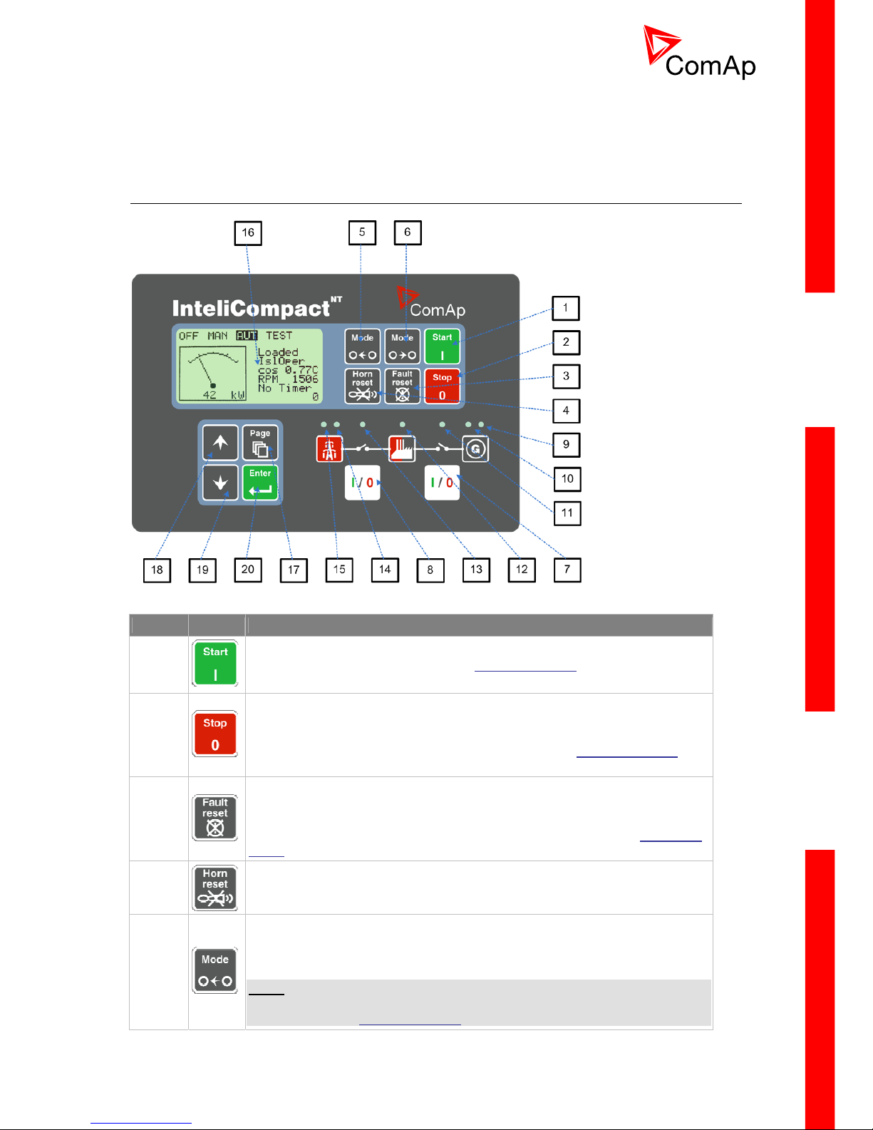
2.1 Front panel elements
G
EN-SET CONTROL BUTTONS
POSITION DESCRIPTION
1
START button. Works in MAN mode only. Press this button to initiate the
start sequence of the engine. See the Reference Guide
– “Engine start”
chapter to learn more about start sequence.
2
STOP button. Works in MAN mode only. Press this button to initiate the stop
sequence of the gen-set. Repeated pressing or holding the button for more
than 2s will cancel current phase of stop sequence (like ramping the power
down or cooling) and next phase will continue. See the Reference Guide
–
“Engine cooldown and stop” chapter to learn more about stop sequence.
3
FAULT RESET button. Use this button to acknowledge alarms and
deactivate the horn output. Inactive alarms will disappear immediately and
status of active alarms will be changed to "confirmed" so they will disappear
as soon as their reasons dismiss. Learn more about alarms in the Reference
Guide – “Alarm management” chapter.
4
HORN RESET button. Use this button to deactivate the horn output without
acknowledging the alarms.
5
MODE LEFT button. Use this button to change the mode. The button works
only if the main screen with the indicator of currently selected mode is
displayed.
NOTE:
This button will not work if the controller mode is forced by one of binary
inputs listed in the Reference Guide – “Operating modes” chapter.
Page 5

I
NTELICOMPACT-NT, SW VERSION 1.3, ©COMAP – SEPTEMBER 2011 REFERENCE GUIDE.PDF 5
6
MODE RIGHT button. Use this button to change the mode. The button works
only if the main screen with the indicator of currently selected mode is
displayed.
NOTE:
This button will not work if the controller mode is forced by one of binary
inputs listed in the Reference Guide – “Operating modes” chapter.
7
GCB button. Works in MAN and TEST modes only. Press this button to open
or close the GCB or start synchronizing manually. Note that certain conditions
must be valid otherwise GCB closing resp. starting of synchronization is
blocked. See the Reference Guide
– “Connecting to the load” chapter for
details.
8
MCB button. Works in MAN and TEST modes only. Press this button to open
or close the MCB or start reverse synchronization manually.
NOTE:
Only in InteliCompact SPTM version.
CAUTION!
You can disconnect the load from the mains supply with this button! Be sure
you know well what you are about to do!
G
EN-SET OPERATION INDICATORS
POSITION DESCRIPTION
9
General alarm. This red indicator lights if at least one alarm is present in the alarm list.
It blinks if a new alarm has appeared and is still not acknowledged.
10
Gen-set voltage OK. This green indicator lights if the generator voltage and frequency
is in limits.
NOTE:
The limits for the generator voltage and frequency are given by setpoints in the Gener
Protect group.
11
GCB position. This green indicator blinks if the forward sychronizing is currently in
progress; otherwise it shows current status of the generator circuit breaker according to
the feedback input.
12 Bus under voltage. This green indicator shows if the bus is under voltage or not.
13
MCB position. This green indicator blinks if the reverse sychronizi ng is currently in
progress; otherwise it shows current status of the mains circuit breaker according to the
feedback input.
NOTE:
Only in InteliCompact SPTM version.
14
Mains voltage OK. This green indicator lights if the mains is evaluated as healthy. See
the Reference guide
– “AMF function” chapter for details about mains evaluation.
NOTE:
Only in InteliCompact SPTM version.
15
Mains failure. This red indicator lights when the mains failure is detected and after the
gen-set has started and is about to take the load it lights permanently until the mains
failure disappears.
NOTE:
Only in InteliCompact SPTM version.
D
ISPLAY AND DISPLAY CONTROL BUTTONS
Page 6

I
NTELICOMPACT-NT, SW VERSION 1.3, ©COMAP – SEPTEMBER 2011 REFERENCE GUIDE.PDF 6
POSITION DESCRIPTION
16 Graphic B/W display, 128x64 pixels
17
PAGE button. Use this button to switch over display pages. See next chapter
for details about display pages and screens structure
18
UP button. Use this button to move up or increase value.
19
DOWN button. Use this button to move down or decrease value.
20
ENTER button. Use this button to finish editing a setpoint or moving right in
the history page.
2.2 User interface modes
There are two modes of the user interface:
• User mode allows the user to go through all screens with measurements and alarms. The
button does not work, i.e. setpoints and history pages are not accessible.
• Engineer mode gives the qualified person full access to all pages and screens.
See the chapter “User interface mode selection” in Reference Guide
to learn how to switch the user
interface mode.
2.3 Display screens and pages structure
The displayed information is structured into "pages" and "screens". Use PAGE button to switch over
the pages.
1. The page Measurement consists of screens which display measured values like voltages,
current, oil pressure etc., computed values like i.e. gen-set power, statistic data and the alarm
list on the last screen.
2. The page Setpoints contains all setpoints organized to groups and also a special group for
entering password.
3. The page History log shows the history log in the order that the last record is displayed first.
NOTE:
The picture below shows the structure of displayed data. The contents of each particular screen may
be slightly different according to the firmware branch and version.
Page 7

I
NTELICOMPACT-NT, SW VERSION 1.3, ©COMAP – SEPTEMBER 2011 REFERENCE GUIDE.PDF 7
S
TRUCTURE OF THE DISPLAYED DATA (BASIC)
Page 8

I
NTELICOMPACT-NT, SW VERSION 1.3, ©COMAP – SEPTEMBER 2011 REFERENCE GUIDE.PDF 8
2.4 View measured values
Press button repeatedly until you see the main screen with the kW meter and mode selector.
Then press
or to select a requested screen within the measurement page.
M
AIN SCREEN
2.5 Setpoints - view and change
1. Press button repeatedly until you see a screen with a list of setpoint groups. Then select
desired group by pressing the
or buttons and finally press button to
continue into the selected group.
2. Now you will see the list of setpoints which belong to the selected group together with their
current setting. Use the
or buttons again to select the setpoint you want to modify
and press
.
3. The current value of the setpoint will appear in the right part under the setpoint name and you
can change it by pressing
or buttons. The rate of changing the value will
accelerate when the button is held down
4. Press
button to confirm the change or to discard it and return to the list of
setpoints of the selected group.
5. Continue with change of another setpoint or press
to return to the list of groups.
L
IST OF GROUPS OF SETPOINTS
Page 9

I
NTELICOMPACT-NT, SW VERSION 1.3, ©COMAP – SEPTEMBER 2011 REFERENCE GUIDE.PDF 9
L
IST OF SETPOINTS WITHIN SELECTED GROUP
E
DITING A SETPOINT
2.6 Browsing the history log
1. Press button repeatedly until you see the main history log screen with the reason
column and the latest record.
NOTE:
The records are numbered in reverse order, i.e. the latest (newest) record is "0" and older
records have "-1", "-2" etc.
2. Use the
button to move over columns within the selected record. Pressing it repeatedly
will move cyclically through the columns, i.e. after last column the first one will be displayed.
3. Use buttons
and to move over the records.
4. Press
button to select another display page.
M
AIN HISTORY LOG SCREEN
NOTE:
The first history record after the controller is switched on, programmed or watchdog reset occurs
contains diagnostic values instead of operational. Some fields in these records seem to have
nonsense values. Do not take these values into account.
Page 10

I
NTELICOMPACT-NT, SW VERSION 1.3, ©COMAP – SEPTEMBER 2011 REFERENCE GUIDE.PDF 10
2.7 Browsing alarms
The Alarmlist and ECU Alarmlist are displayed on the last two screens in the measurement page. If
the main screen is displayed then the Alarmlist screen will appear automatically always when a new
alarm occurs. It can be also displayed manually as described in the chapter “View measured values”
in Reference Guide
.
• Use the
to move over the alarms in the ECU Alarmlist. Details of the selected alarm are
displayed in the bottom line.
• Press
button to reset alarms.
• Active alarms are displayed as white text on black background. It means the alarm is stil
active, i.e. the appropriate alarm conditions are still present.
• Inactive alarms are displayed as black text on white background. It means the alarm is no
more active, i.e. the appropriate alarm conditions are gone.
• Not confirmed alarms are displayed with an asterisk. It means the alarm is still not
acknowledged (confirmed).
A
LARMLIST
ECU
ALARMLIST
NOTE:
The ECU AlarmList is visible only if an ECU is configured.
2.8 Entering the password
The password must be entered prior adjusting setpoints that are password-protected. Pa ssword is
located in the first group of setpoints and the way how to enter or change password is similar t o
change of setpoints as described in the “Setpoints” chapter in Reference Guide
.
NOTE:
It is possible to change only passwords of the same or lower level than actually entered password!
Page 11

I
NTELICOMPACT-NT, SW VERSION 1.3, ©COMAP – SEPTEMBER 2011 REFERENCE GUIDE.PDF 11
NOTE:
Lost password? Display the information screen which contains the serial number and a password
decode number as is described in the chapter below. Write down both numbers and send a request to
retrieve the passord to your local distributor containing these two numbers. You can also save and
send an archive instead.
2.9 Controller information screen
1. Press the button repeatedly until you will see the main controller screen with the mode
2. Hold down the
selector and kW analog meter.
button and simultaneously press the button to see the controller
disappear automatically after 5 secs
4. Press the button
information screen.
3. The information screen will
again within 5s to switch to language selection screen.
5. Press the button again to switch to the user interface mode selection screen. This
6. Next pressing of the button
screen also contains serial number and password decode number.
switches back to the information screen.
7. Press the button
to get back to the controller main screen.
Page 12

I
NTELICOMPACT-NT, SW VERSION 1.3, ©COMAP – SEPTEMBER 2011 REFERENCE GUIDE.PDF 12
S
TRUCTURE OF THE DISPLAYED DATA (ADVANCE)
The information screen contains following information:
• Controller Name
• Firmware identification string
• Serial number of the controller
• ESF version
• Firmware version, application version
• Application type
• Branch name
NOTE:
ESF version is shown only when electronic engine is configured.
Page 13

I
NTELICOMPACT-NT, SW VERSION 1.3, ©COMAP – SEPTEMBER 2011 REFERENCE GUIDE.PDF 13
2.10 Controller language selection
There are two languages available in the controller. Default languages are English and Chin ese. The
languages can be changed or modified during the configuration in LiteEdit. Please see the LiteEdit
documentation for details.
To switch the controller language:
1. Display the information screen as described above.
2. While the information screen is still displayed, press the
button.
3. Language menu will appear, use
or buttons to select the desired language.
4. Press
to confirm the selection.
2.11 User interface mode selection
To switch the User interface mode, follow instructions below:
1. Display the information screen as described above.
2. While the information screen is still displayed, press the
button twice.
3. User interface mode menu will appear, use
or buttons to select the desired mode
(User or Engineer).
4. Press
to confirm the selection.
2.12 Display contrast adjustment
1. Press the button repeatedly until you will see the main controller screen with the mode
selector and kW analog meter.
2. Hold down the
button and simultaneously press button or repeatedly to
increase or decrease the contrast.
 Loading...