

Page 1
Copyright © 2015 ComAp a.s.
ComAp a.s..
Kundratka 2359/17, 180 00 Praha 8, Czech Republic
Tel: +420 266 790 611, Fax: +420 266 316 647
Technical support hotline: +420 266 790 666
E-mail: info@comap.cz, www.comap.cz
Compact Controller for Stand-by and Parallel Operating Gen-sets
Inteli New Technology
Modular Generator Controller
Multiple Internal engines application – SW configuration
MINT
IG-NT GC, IG-NTC GC, IS-NT,IG-NT-BB, IG-NTC-BB, IS-NTC-BB
Software version IGS-NT-GeCon-MARINE-3.2, July 2015
REFERENCE GUIDE
Page 2

2
Table of Contents
Table of Contents ............................................................................................................................................... 2
General guidelines .............................................................................................................................................. 4
What is described in this manual? ................................................................................................................. 4
Dangerous voltage ......................................................................................................................................... 5
Adjust set points ............................................................................................................................................. 5
Clarification of notation ................................................................................................................................... 5
Available Firmware and Archive sets ................................................................................................................. 6
General description ............................................................................................................................................ 7
Description of the controller system (with all options) .................................................................................... 7
Comparing of IGS-NT-GeCon-MARINE 3.2 with standard gen-set fw .......................................................... 7
Available documentation ................................................................................................................................ 7
Example of interconnection GeCon x Engine controller ..................................................................................... 9
Functions .......................................................................................................................................................... 11
Modified setpoints ........................................................................................................................................ 11
Controller modes .......................................................................................................................................... 12
Power management ..................................................................................................................................... 16
DeadBusStart function ................................................................................................................................. 20
Load shedding .............................................................................................................................................. 20
DROOP ........................................................................................................................................................ 22
Protection mode settings .............................................................................................................................. 24
External breaker control ............................................................................................................................... 24
Heavy consumers support ........................................................................................................................... 25
Variable speed support ................................................................................................................................ 26
Force value – step by step guide ................................................................................................................. 27
Values for continuous writing from external sources ................................................................................... 29
User Buttons................................................................................................................................................. 29
User Mask function ...................................................................................................................................... 30
Remote Control Function ............................................................................................................................. 31
Virtual Peripheral Inputs-Outputs (VPIO) module ........................................................................................ 32
Shared Inputs and Outputs .......................................................................................................................... 32
Distributed Binary Inputs and Outputs ......................................................................................................... 34
Modbus Reading and Writing ....................................................................................................................... 35
User MODBUS ............................................................................................................................................. 35
Modbus Switches ......................................................................................................................................... 36
Power Formats ............................................................................................................................................. 36
PLC functions ............................................................................................................................................... 36
Multi language support ................................................................................................................................. 37
ECU interface customizing ........................................................................................................................... 37
Volt/PF control adjustment ........................................................................................................................... 37
Sync/load control adjustment ....................................................................................................................... 39
Protections and Alarm management ................................................................................................................ 40
Gen-set operation states .................................................................................................................................. 47
SynchroScope mode ........................................................................................................................................ 48
Inputs and Outputs ........................................................................................................................................... 49
Virtual and physical modules ....................................................................................................................... 49
Analog outputs ............................................................................................................................................. 49
Setpoints ........................................................................................................................................................... 51
ProcessControl ............................................................................................................................................. 51
Basic settings ............................................................................................................................................... 57
Delays/Timers .............................................................................................................................................. 68
Analog protect .............................................................................................................................................. 71
Gener protect ............................................................................................................................................... 72
Pwr management ......................................................................................................................................... 79
HeavyConsumers ......................................................................................................................................... 84
Sync/Load ctrl............................................................................................................................................... 84
Sync/load control adjustment ....................................................................................................................... 84
Inteli NT GeCon-MARINE MINT, SW Version 3.2, ©ComAp – July 2015
IGS-NT-GeCon-MARINE-MINT-3.2.PDF
Page 3

3
Volt/PF ctrl .................................................................................................................................................... 89
Force value ................................................................................................................................................... 91
Load shedding .............................................................................................................................................. 92
Timer settings ............................................................................................................................................... 94
Act. calls/SMS .............................................................................................................................................. 94
Date/Time ..................................................................................................................................................... 96
Table of values ................................................................................................................................................. 98
Group: Engine values ................................................................................................................................... 98
Group: Gener values .................................................................................................................................... 99
Group: Bus values ...................................................................................................................................... 106
Group: Power management ....................................................................................................................... 109
Group: Sync/Load ctrl ................................................................................................................................ 112
Group: Volt/PF ctrl ...................................................................................................................................... 114
Group: Force value .................................................................................................................................... 114
Group: Load shedding ................................................................................................................................ 116
Group: Analog CU ...................................................................................................................................... 116
Group: Bin inputs CU ................................................................................................................................. 117
Group: Bin outputs CU ............................................................................................................................... 118
Group: Log Bout ......................................................................................................................................... 118
Group: Info ................................................................................................................................................. 122
Group: Statistics ......................................................................................................................................... 128
Table of binary input functions........................................................................................................................ 133
HeavyConsumers ....................................................................................................................................... 174
Table of analog input functions ...................................................................................................................... 175
Table of binary output functions ..................................................................................................................... 184
Controller configuration and monitoring ......................................................................................................... 221
Direct connection to the PC ....................................................................................................................... 221
GenConfig functions ................................................................................................................................... 221
InteliMonitor ................................................................................................................................................ 222
Modbus protocol ......................................................................................................................................... 222
Value and setpoint codes ........................................................................................................................... 222
Technical data ............................................................................................................................................ 222
Inteli NT GeCon-MARINE MINT, SW Version 3.2, ©ComAp – July 2015
IGS-NT-GeCon-MARINE-MINT-3.2.PDF
Page 4
4
General guidelines
Following described machine complies with the appropriate basic safety and health
requirement of the EC Low Voltage Directive No: 73/23 / EEC and EC
Electromagnetic Compatibility Directive 89/336 / EEC based on its design and type,
as brought into circulation by us.
What is described in this manual?
This manual describes IGS-NT -GeCon-MARINE- „MINT“ software configuration. The Generator controller
software configuration is designed for multiple sets applications with internal load sharer and synchronizer.
What is the purpose of this manual?
This manual provides general information on how to configure and operate the controller.
This manual is intended for use by:
Operators of gen-sets/generators
Gen-set/generator control panel builders
For everybody who is concerned with installation, operation and maintenance of the genset/generator
!! Warnings !!
Remote control
The IGS-NT controller can be remotely controlled. In case that maintenance needs to be done to the genset, check the following to ensure that the engine cannot be started.
To be sure:
Disconnect remote control via RS232 line
Disconnect input REMOTE START/STOP
or
Disconnect output STARTER and output GCB CLOSE/OPEN
The controller contains a large number of configurable setpoints, because of this it is impossible to describe
all of its functions. These are subject to change from SW version to SW version. This manual only describes
the product and is not guaranteed to be set for your application on arrival.
Text
PAGE (Capital letters in the frame) buttons on the front panel
Break Return (Italic) set points
Generator protections (Bold) Set point group
REMOTE START/STOP (Capital letters) binary inputs and outputs
Cyan background Valid for IS-NT only
Conformity declaration
Note:
ComAp believes that all information provided herein is correct and reliable and reserves the right to update
at any time. ComAp does not assume any responsibility for its use unless otherwise expressly undertaken.
Inteli NT GeCon-MARINE MINT, SW Version 3.2, ©ComAp – July 2015
IGS-NT-GeCon-MARINE-MINT-3.2.PDF
Page 5
5
Be aware that the binary outputs can change state during and after software
reprogramming (before the controller is used again ensure that the proper
configuration and setpoint settings are set in the controller)!!!
Be aware that gen-set can automatically or remotely start !!!
Switch the controller to SEM mode and disconnect the Binary outputs Starter and Fuel
to avoid unexpected automatic start of gen-set and GCB closing.
!!! CAUTION !!!
Dangerous voltage
The terminals for voltage and current measurement should never be touched.
Properly connect the grounding terminals.
Do not disconnect the CT terminals for any reason.
Adjust set points
All setpoints are preadjusted to their typical values. But the set points in the “Basic settings” settings
group !!must!! be adjusted before the first startup of the gen-set.
!!! WRONG ADJUSTMENT OF BASIC PARAMETERS
CAN DESTROY THE GEN-SET !!!
The following instructions are for qualified personnel only. To avoid personal injury do
not perform any action not specified in this User guide !!!
WARNING – VERY IMPORTANT !!!
Clarification of notation
HINT
This type of paragraph points out details to help user installation/configuration.
NOTE:
This type of paragraph calls readers’ attention to a notice or related theme.
CAUTION!
This type of paragraph highlights a procedure, adjustment, etc. which may cause damage or improper
functioning of the equipment if not carried out correctly and may not be clear at first sight.
WARNING!
This type of paragraph indicates things, procedures, adjustments, etc. which demand a high level of
attention, otherwise personal injury or death may occur.
EXAMPLE:
This type of paragraph indicates examples of usage for illustrational purposes.
Inteli NT GeCon-MARINE MINT, SW Version 3.2, ©ComAp – July 2015
IGS-NT-GeCon-MARINE-MINT-3.2.PDF
Page 6

6
Available Firmware and Archive sets
InteliGen NT GC
InteliGen NTC GC
InteliGen NT BaseBox
InteliGen NTC BaseBox
InteliSys NT BaseBox
InteliSys NTC BaseBox
IG-NT-GC-GeCon-MARINE-3.2
IG-NT-BB-GeCon-MARINE-3.2
IS-NT-GeCon-MARINE-3.2
InteliGen NT GC
InteliGen NTC GC
InteliGen NT BaseBox
InteliGen NTC BaseBox
InteliSys NT BaseBox
InteliSys NTC BaseBox
IG-GC-GeCon-MARINE -SPTM-
3.2
IG-BB-GeCon-MARINE -SPTM-
3.2
IS- GeCon-MARINE-SPTM-3.2
IG-GC-GeCon-MARINE -SPI-
3.2
IG-BB-GeCon-MARINE -SPI-3.2
IS- GeCon-MARINE-SPI-3.2
IG-GC-GeCon-MARINE -MINT-
3.2
IG-BB-GeCon-MARINE -MINT-
3.2
IS- GeCon-MARINE-MINT-3.2
IG-GC-GeCon-MARINE -
COMBI-3.2
IG-BB-GeCon-MARINE -
COMBI-3.2
IS- GeCon-MARINE-COMBI-3.2
For suitable firmware for your controller please consult this table:
Firmware (*.mhx)
Archives (*.ant)
Some features are available only in InteliGen NT Basebox, InteliGen NTC Basebox and InteliSys NT. These
features are highlighted by green background.
Features which are not available in InteliGenNT GC controller:
User MODBUS
Distributed Binary Inputs and Outputs
Inteli NT GeCon-MARINE MINT, SW Version 3.2, ©ComAp – July 2015
IGS-NT-GeCon-MARINE-MINT-3.2.PDF
Page 7

7
General description
PDF FILE
DESCRIPTION
IGS-NT & ID-DCU Accessory Modules 02-
2015.pdf
Thorough description of accessory modules for IGS-NT
family, technical data, information about installation of the
modules, how to connect them to controller and set them
properly.
IGS-NT Troubleshooting Guide 08-2014.pdf
How to solve most common troubles with InteliGen NT and
InteliSys NT controllers. Including the list of alarm massages.
IGS-NT Communication Guide 09-2014.pdf
Communication guide for IG/IS-NT controllers. It contains
information how to connect control unit and all
communication features descriptions
IGS-NT Installation Guide 08-2014.pdf
Installation guide for IG/IS-NT controllers. It contains
technical information about controler and extension modules
IGS-NT Application Guide 05-2013.pdf
Application guide for IG/IS-NT controllers. It refers to
application and typical installation settings and sites
structures
Description of the controller system (with all options)
NT Family controllers are comprehensive AMF-controllers for single and multiple generating sets operating
in stand-by or parallel modes. A modular construction allows upgrades to different levels of complexity in
order to provide the best solution for various customer applications.
NT Family controllers are equipped with a powerful graphic display showing icons, symbols and bar-graphs
for intuitive operation, which sets, together with high functionality, new standards in Gen-set controls.
The controller automatically starts the gen-set, closes the Gen-set C.B. when all conditions are met, then
stops the engine* (* sw GeCon opens GCB only, not stops the engine) on external signal or by pressing
push buttons.
Parallel to the Mains operation is a standard feature. Isolated parallel and Power Management System
support are optional. Forward and reverse synchronizing, Generator protections, Mains protection including
vector shift, load and power factor control are the major functions provided. Interfacing to foreign
synchronizers and load sharers is supported.
The key feature of the controller is its easy-to-use operation and installation. Predefined configurations for
typical applications are available as well as user-defined configurations for special applications.
Comparing of IGS-NT-GeCon-MARINE 3.2 with standard gen-set fw
GeCon does not take care of Engine control
GeCon accepts in SEM mode external control of GCB and Engine
GeCon can control the engine via Binary start/stop output signals only – see below. The
independent Engine controller (e.g. ID-DCU) is expected.
Synchronizing and unloading timeouts can be disabled by setpoint setting (or Force value function)
All regulations (load, VAr sharing, frequency, voltage) can be disabled by setpoint change or by
Force value.
Interface GeCon to engine controller is provided by I/O wires no by communication line.
Available documentation
Inteli NT GeCon-MARINE MINT, SW Version 3.2, ©ComAp – July 2015
IGS-NT-GeCon-MARINE-MINT-3.2.PDF
Page 8

8
IGS-NT Operator Guide 01-2014.pdf
Operator guide for IG/IS-NT
Inteli NT GeCon-MARINE MINT, SW Version 3.2, ©ComAp – July 2015
IGS-NT-GeCon-MARINE-MINT-3.2.PDF
Page 9
9
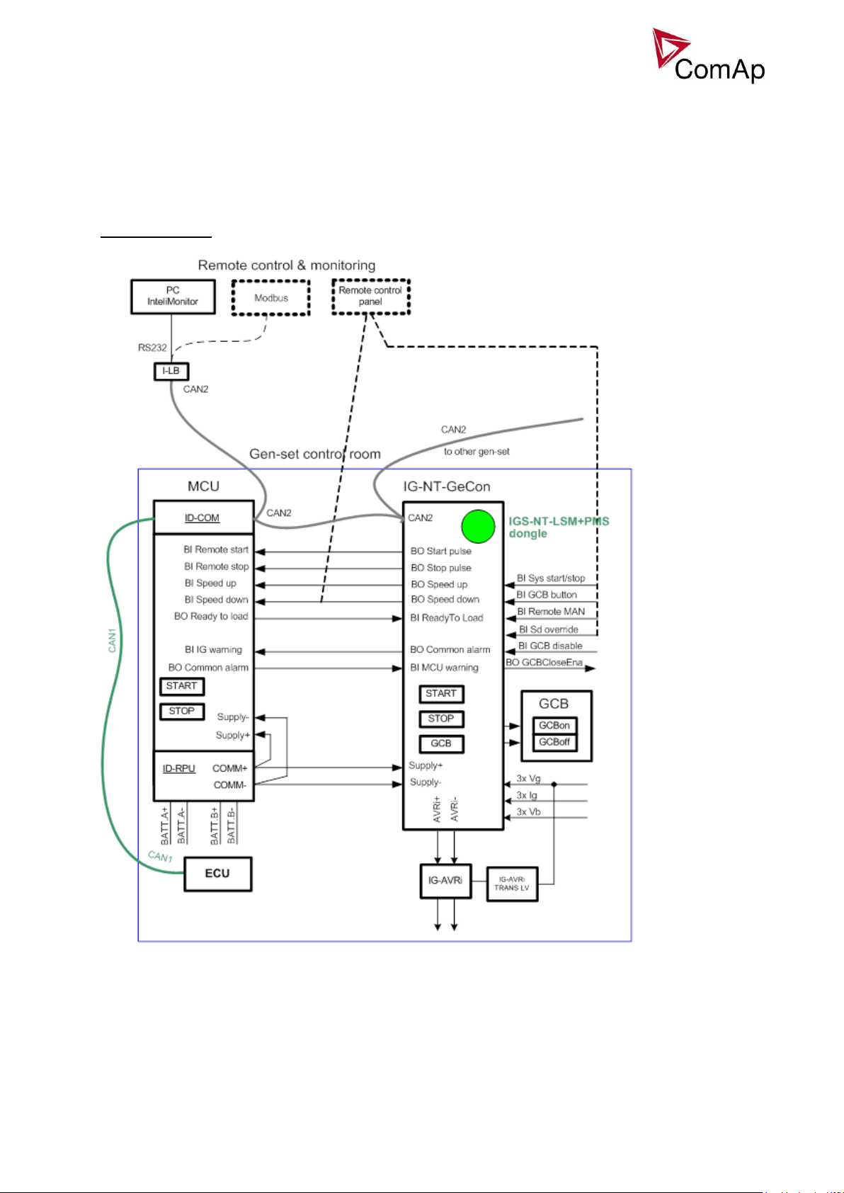
Example of interconnection
GeCon x Engine controller
Schematic wiring:
Important signals/ interconnections:
From GeCon side:
BO: Start pulse, Stop pulse - for sending Start and Stop signals
Speed control (during synchronisation, regulation):
BO: Speed Up, Speed Down or Aout SG out
Inteli NT GeCon-MARINE MINT, SW Version 3.2, ©ComAp – July 2015
IGS-NT-GeCon-MARINE-MINT-3.2.PDF
Page 10

10
BI: ReadyToLoad – signal from Engine unit – it means that Engine is ready (speed is ok, no 2nd level
alarms) and can be loaded.
Other signals:
- Information about Warnings / SD in one unit can be sent to second unit.
- ECU – in case of Ecu communicating via CAN bus J1939 – GeCon can be connected to CAN1 for
showing ECU values on the display
- Interconnection on CAN2:
o For Time and Date synchronisation only- in case of IGS-NT and ID-DCU
o In case of connection IB-NT or I-LB+ - you can monitor both kind of units (IGS-NT, ID-DCU)
o In case of connection display – you can switch between both kind of units (IGS-NT, ID-DCU)
Inteli NT GeCon-MARINE MINT, SW Version 3.2, ©ComAp – July 2015
IGS-NT-GeCon-MARINE-MINT-3.2.PDF
Page 11
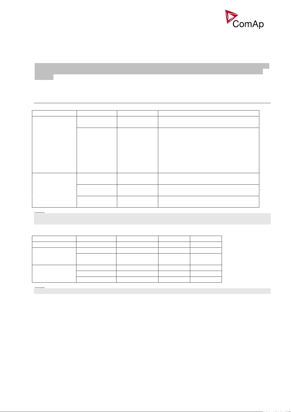
11
Functions
Group
Setpoint
Option
Function
Process control
StartStopBtn
ENABLED
DISABLED
Standard panel Start/Stop buttons function.
Panel Start/Stop buttons are disabled.
ProtectionMode
ACTIVE
NOT ACTIVE
ACTIVE:
2-nd level protections are evaluated, GCB
or MCB is controlled.
NOT ACTIVE:
2-nd level protections are evaluated, GCB
or MCB is NOT opened.
Exceptions are Emerg Stop and alarms
types Sdoverride.
Sync/Load ctrl
Sync timeout
1-1800s
NO TIMEOUT
Standard MINT function.
Unlimited synchronizing time.
GCB open level
1-100%
NO LEVEL
Standard MINT function.
No generator power open level detection.
GCB open del
1-1800s
NO TIMEOUT
Standard MINT function.
Unlimited unloading procedure.
“HAND”
SEM
AUT
Basic setting
ControllerMode
SEM
SEM
AUT
Process control
StartStopBtn
DISABLED
ENABLED
ENABLED
ProtectionMode
NOT
ACTIVE/ACTIVE
ACTIVE
ACTIVE
Sync/Load ctrl
Sync timeout
NO TIMEOUT
1-1800s
1-1800s
GCB open level
NO LEVEL
1-100%
1-100%
GCB open del
NO TIMEOUT
1-1800s
1-1800s
For the IGS-NT-GeCon-MARINE is possible to use IGS-NT-LSM+PMS or IGS-NT-GeCon-LSM+PMS dongle
which enables the Load sharing and Power management functions. (both types of dongles have the same
function)
Modified setpoints
Below mentioned are GeCon specific setpoints only.
Hint:
All above mentioned setpoints can be Forced by Binary input(s) to another value (or switched between
ENABLED and DISABLED).
Based on setpoint settings there are three possible operational modes HAND – SEM - AUT:
Hint:
It is possible to configure (Force value) “HAND” – SEM switching via Binary input.
Inteli NT GeCon-MARINE MINT, SW Version 3.2, ©ComAp – July 2015
IGS-NT-GeCon-MARINE-MINT-3.2.PDF
Page 12

12
Controller modes
OFF mode
Use OFF mode to block controller functions (even if is power on). OFF mode is used for controller firmware
or configuration change.
Binary outputs (e.g. GCB CLOSE/OPEN) are not energized, all closed Binary outputs are opened when
controller is switched to OFF mode.
Gen-set cannot be started and operated from IGS-NT-GeCon controller – no response for panel buttons and
Binary input commands.
Hint:
Switching to OFF mode is blocked on running engine to avoid accidental engine stop by mode change or by
firmware or configuration programming.
Inteli NT GeCon-MARINE MINT, SW Version 3.2, ©ComAp – July 2015
IGS-NT-GeCon-MARINE-MINT-3.2.PDF
Page 13
13
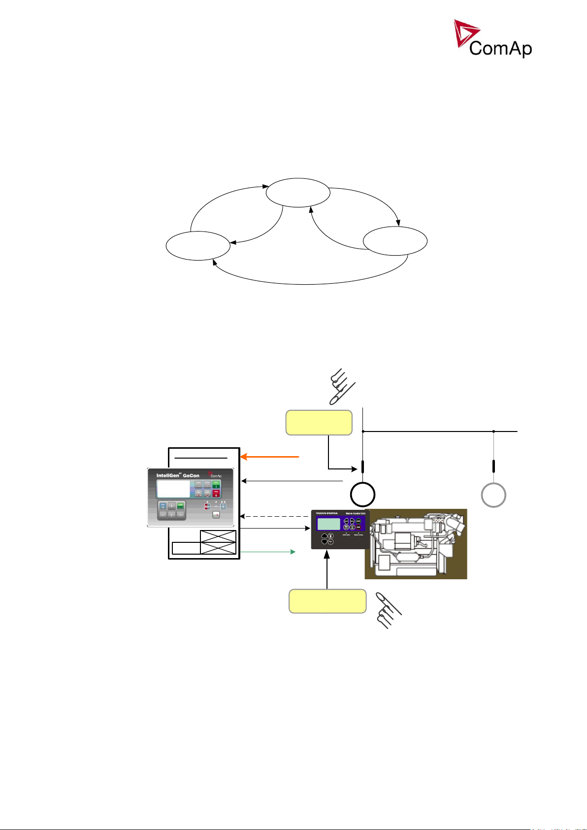
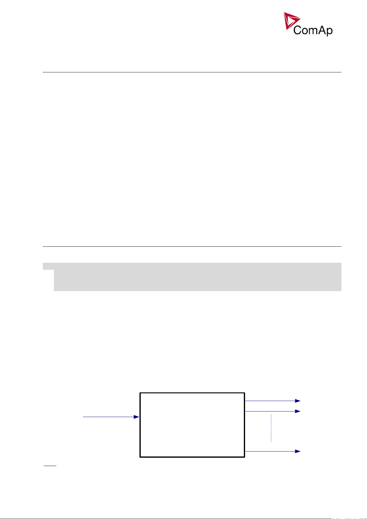
MAN mode
Stopped
Running
Loaded
BI:ReadyToLoad
BI:GCB feedback active
BI:GCB feedback
not active
BI:ReadyTo
Load - deact
BI:ReadyTo
Load - deact
IG-EE GeCon
MINT
MCU
GCB feedback
GCB
close/open
Vg, Ig, Vb
RS232 - PC
Speed control
(Sync/Load ctrl)
GCB
START
STOP
(ReadyToLoad)
G
G
External Engine
Start / Stop
External GCB
Close / Open
generator
measuring
Process control: StartStopBtn = DISABLED
ProtectionMode = NOT ACTIVE
Sync/Load ctrl: Sync timeout = NO TIMEOUT
GCB open level = NO LEVEL
GCB open del = NO TIMEOUT
MCU
In MANual mode, the controller evaluates configured protections only(when LBI:ReadyToLoad=1 only). All
regulation loops are disabled, not active. Controller’s state changes based on sensed signals ReadyToLoad
and GCB feedback. In case of some active protection, this is signalized by appropriate binary outputs.
Engine cannot be started from GeCon, GeCon cannot close the GCB, etc..,only opens GCB in cause SD
alarm and Setpoint:Protection mode:ACTIVE.
Controller flow chart in MAN mode
HAND mode
Hand mode is a special type of SEM mode. In Hand mode, the panel Start, Stop buttons are not working,
GCB is supposed to be controlled externally. The Hand mode is achieved by setpoints adjustment - see the
following picture.
Inteli NT GeCon-MARINE MINT, SW Version 3.2, ©ComAp – July 2015
IGS-NT-GeCon-MARINE-MINT-3.2.PDF
Page 14
14
SEM mode
Engine start can be activated from
o Engine controller (e.g. ID-DCU, ID-MCU)
o GeCon panel – Start button
o GeCon BI: StartButton
o Remotely e.g. from InteliMonitor
GeCon BI: ReadyToLoad initiates GeCon “Running” state” - activates Gener protect: Min stab
time a Max stab time within the generator electric protections are activated.
Gen-set is loaded/unloaded from
o GeCon panel – GCB button
o GeCon BI: GCBButton
o Direct GCB “hand” control
o Remotely e.g. from InteliMonitor
o LBI: Gen unload
GCB closing from controller can be blocked by BI: GCB disable (does not block synchronization process)
Controller flow chart in SEM mode:
Inteli NT GeCon-MARINE MINT, SW Version 3.2, ©ComAp – July 2015
IGS-NT-GeCon-MARINE-MINT-3.2.PDF
Page 15

15
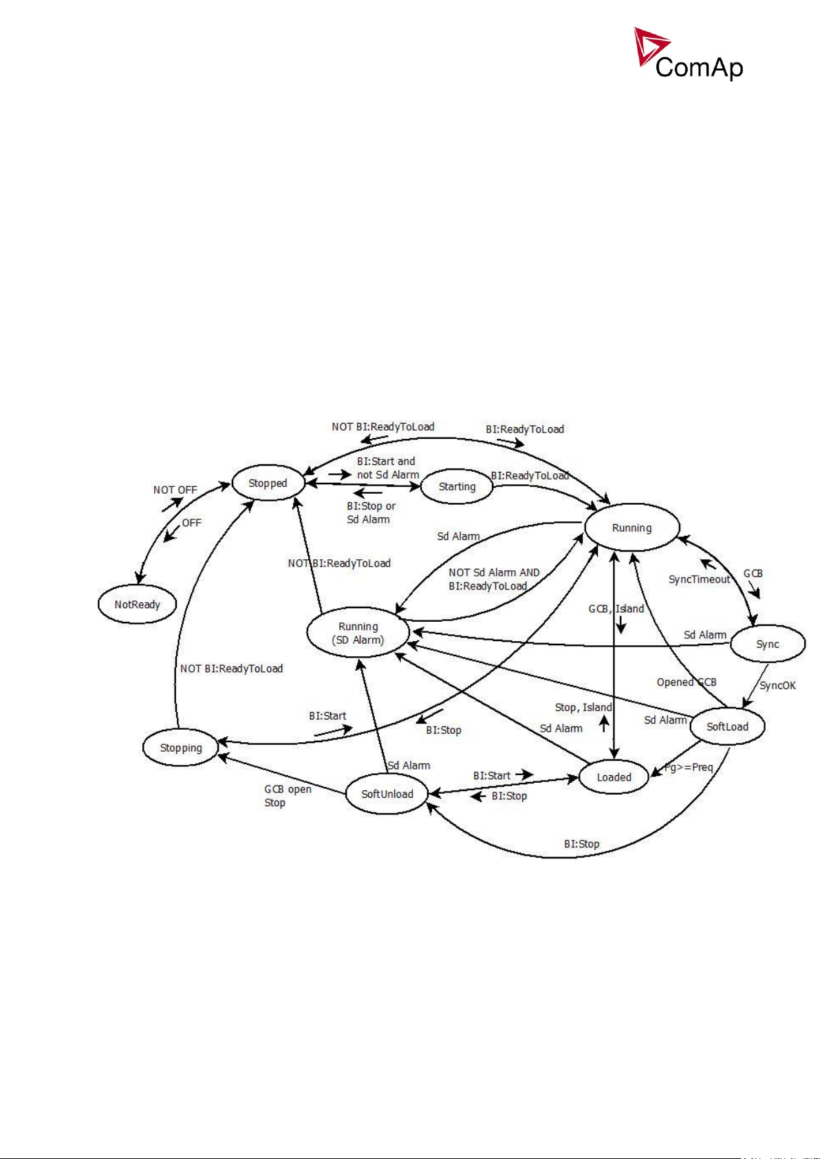
AUT mode
Engine start or Power management is activated from GeCon BI: Sys start/stop
GeCon BI: ReadyToLoad initiates GeCon “Running” state” - activates Gener protect: Min stab
time a Max stab time within the generator electric protections are activated.
Gen-set starts synchronizing and is loaded/unloaded automatically based on
o Power management setting
o GeCon BI: Sys start/stop
GeCon will stop engine started from engine controller when BI Sys start/stop or due to Power
management function.
Controller flow chart in AUT mode:
Inteli NT GeCon-MARINE MINT, SW Version 3.2, ©ComAp – July 2015
IGS-NT-GeCon-MARINE-MINT-3.2.PDF
Page 16
16
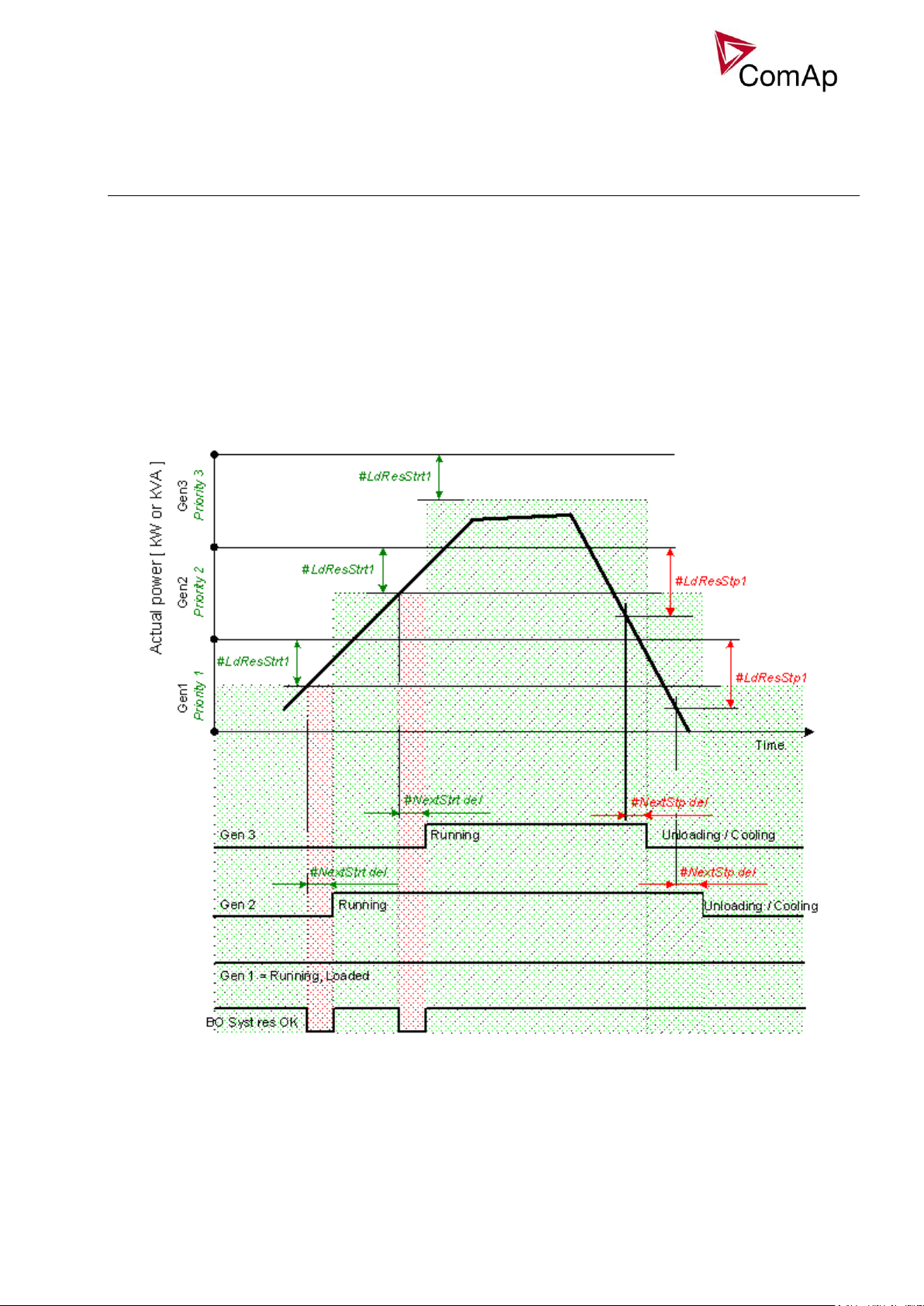
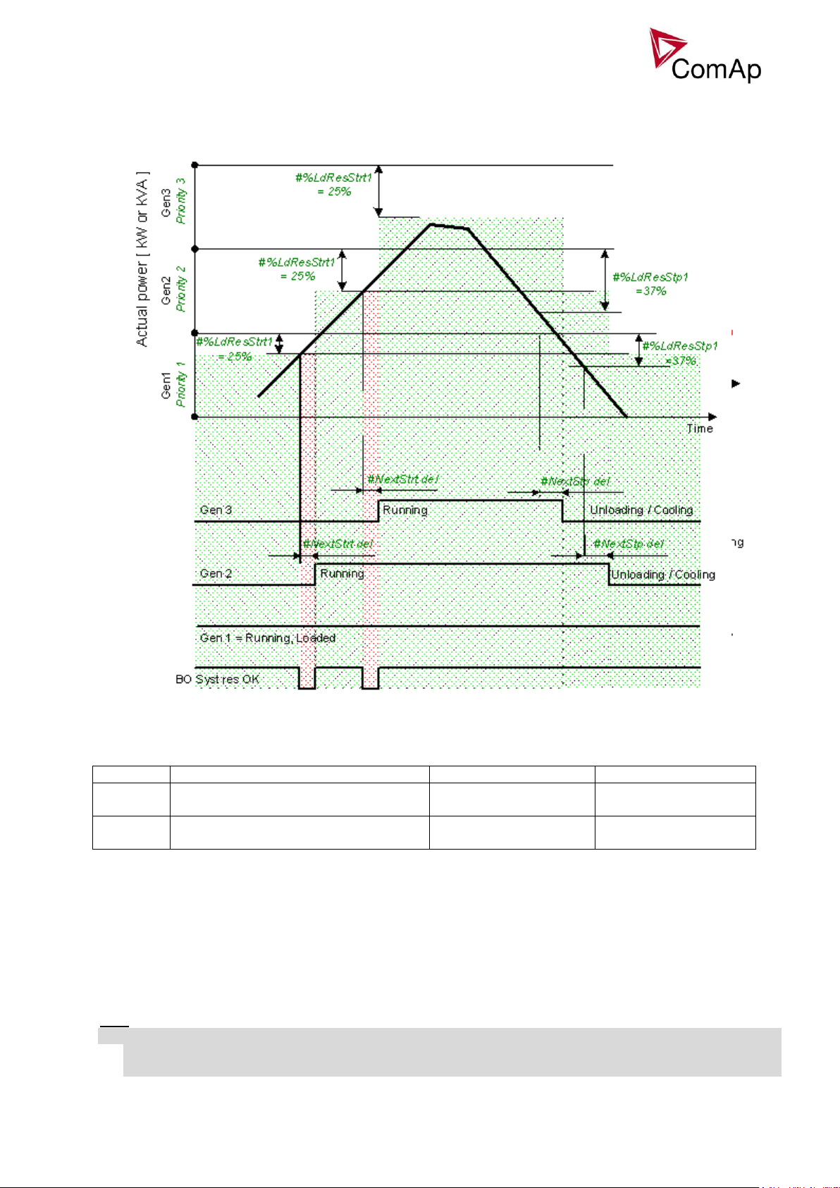
Power management
Automatic gen-set start / stop function based on load changes and/or Running hours or Generator size.
Following functions are available:
Power management in kW
Guarantees adjustable load reserve (load step) in kW. Suitable for load demand-based optimization.
Activation: #Pwr mgmt mode = ABS (kW)
Power management in kVA
Guarantees adjustable load reserve (load step) in kVA. Suitable for generator- or busbar dimensioningbased optimization.
Activation: #Pwr mgmt mode = ABS (kVA)
Relative power management in %
Guarantees that the engines will be not continuously loaded more than to a certain level, leaving less than
selected relative load reserve. Suitable for engine life-based optimization.
Activation: #Pwr mgmt mode = REL (%)
Inteli NT GeCon-MARINE MINT, SW Version 3.2, ©ComAp – July 2015
IGS-NT-GeCon-MARINE-MINT-3.2.PDF
Page 17
17
Reserve
Actual Reserve
Start condition
Stop condition
Absolute
kW / kVA
ARstrt = ΣPg
Nom
– ΣPg
Act
ARstp = ΣPg*
Nom
– ΣPg
Act
ARstrt < #LdResStrt
ARstp > #LdResStp
Relative
%
RRstrt = (ΣPg
Nom
– ΣPg
Act
) / ΣPg
Nom
RRstp = (ΣPg*
Nom
– ΣPg
Act
) / ΣPg*
Nom
RRstrt < #%LdResStrt
RRstp > #%LdResStp
ARstrt
Actual Absolute reserve in kW or kVA - for engine start calculation.
ARstp
Actual Absolute reserves in kW or kVA - for engine stop calculation.
RRstrt
Actual Relative reserve in % - for engine start calculation.
RRstp
Actual Relative reserves in % - for engine stop calculation.
ΣPg
Nom
Sum of Nominal power of all gen-sets on the bus.
ΣPg*
Nom
Sum of Nominal power of all gen-sets on the bus apart of the one, which is going to be stopped.
ΣPg
Act
Sum of Actual power of all gen-sets on the bus = system load.
Start/Stop conditions in Power management
Where
Hint:
Optional functions in absolute or relative Power management are:
- Running hours balancing (equalization),
- Load demand (different size) engines swap and
Inteli NT GeCon-MARINE MINT, SW Version 3.2, ©ComAp – July 2015
IGS-NT-GeCon-MARINE-MINT-3.2.PDF
Page 18
18
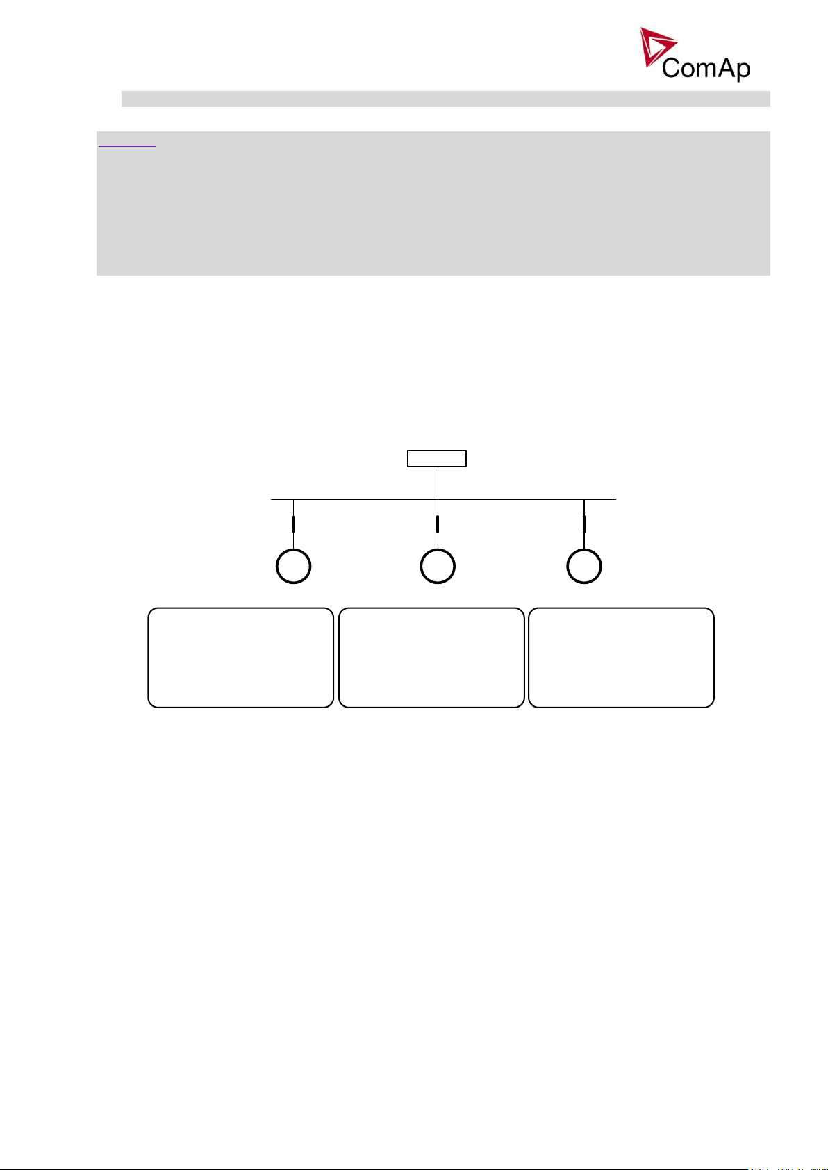
G1 G2 G3
LOAD
1.controller 2.controller 3.controller
Basic settings:
Contr.addr = 1
Pwr management:
#Pwr mgmt mode = RUN HOURS EQU
Priority ctrl = MASTER
RunHoursBase = 100 h
#RunHrsMaxDiff = 10 h
Control group = COMMON
Basic settings:
Contr.addr = 2
Pwr management:
#Pwr mgmt mode = RUN HOURS EQU
Priority ctrl = SLAVE
RunHoursBase = 200 h
#RunHrsMaxDiff = 10 h
Control group = COMMON
Basic settings:
Contr.addr = 3
Pwr management:
#Pwr mgmt mode = RUN HOURS EQU
Priority ctrl = SLAVE
RunHoursBase = 300 h
#RunHrsMaxDiff = 10 h
Control group = COMMON
- Power management of two or more gen-set groups (bus tie support).
CAUTION!
The function of the controller is designed to handle the maximum sum of nominal power at 32000kW
(3200.0kW, 320.00MW depending on the power format in the controller). If the sum of nominal power of all
gen-sets connected to the intercontroller CAN exceeds these values the power format needs to be changed
accordingly.
Example: There are 20 gen-sets each with 2000kW of nominal power. The sum of the nominal power is
40000kW. Therefore the power format in kW cannot be used because the sum exceeds 32767. Therefore
power format in MW needs to be chosen because the sum in MW is 40MW (it does not exceeds 320.00MW).
Running hours balancing
The gen-sets priorities are automatically swapped to balance engine running hours. Up to 32 controllers are
supported.
Activation: #PriorAutoSwap = RUN HOURS EQU
Important setpoints: RunHoursBase , #RunHrsMaxDiff
Different sized engines (Load demand) swap
Three running engines (priorities) are swapped based on load demand (one “small” engine runs on “small”
load and swaps to another one “big” engine that runs when load increases).
Activation: #PriorAutoSwap = LD DEMAND SWAP
Important setpoints: #PwrBandContr1, #PwrBandContr2, #PwrBandContr3, #PwrBandContr4,
#PwrBandChngDe.
Inteli NT GeCon-MARINE MINT, SW Version 3.2, ©ComAp – July 2015
IGS-NT-GeCon-MARINE-MINT-3.2.PDF
Page 19
19
G1 G2 G3
LOAD
1.controller 2.controller 3.controller
Basic settings:
Contr.addr = 1
Pwr management:
#Pwr mgmt mode = LD DEMAND SWAP
Priority ctrl = MASTER
#PwrBandContr1 = 1
#PwrBandContr2 = 2
#PwrBandContr3 = 2+3
#PwrBandChngDe = 10 s
Control group = COMMON
Basic settings:
Contr.addr = 2
Pwr management:
#Pwr mgmt mode = LD DEMAND SWAP
Priority ctrl = SLAVE
#PwrBandContr1 = 1
#PwrBandContr2 = 2
#PwrBandContr3 = 2+3
#PwrBandChngDe = 10 s
Control group = COMMON
Basic settings:
Contr.addr = 3
Pwr management:
#Pwr mgmt mode = LD DEMAND SWAP
Priority ctrl = SLAVE
#PwrBandContr1 = 1
#PwrBandContr2 = 2
#PwrBandContr3 = 2+3
#PwrBandChngDe = 10 s
Control group = COMMON
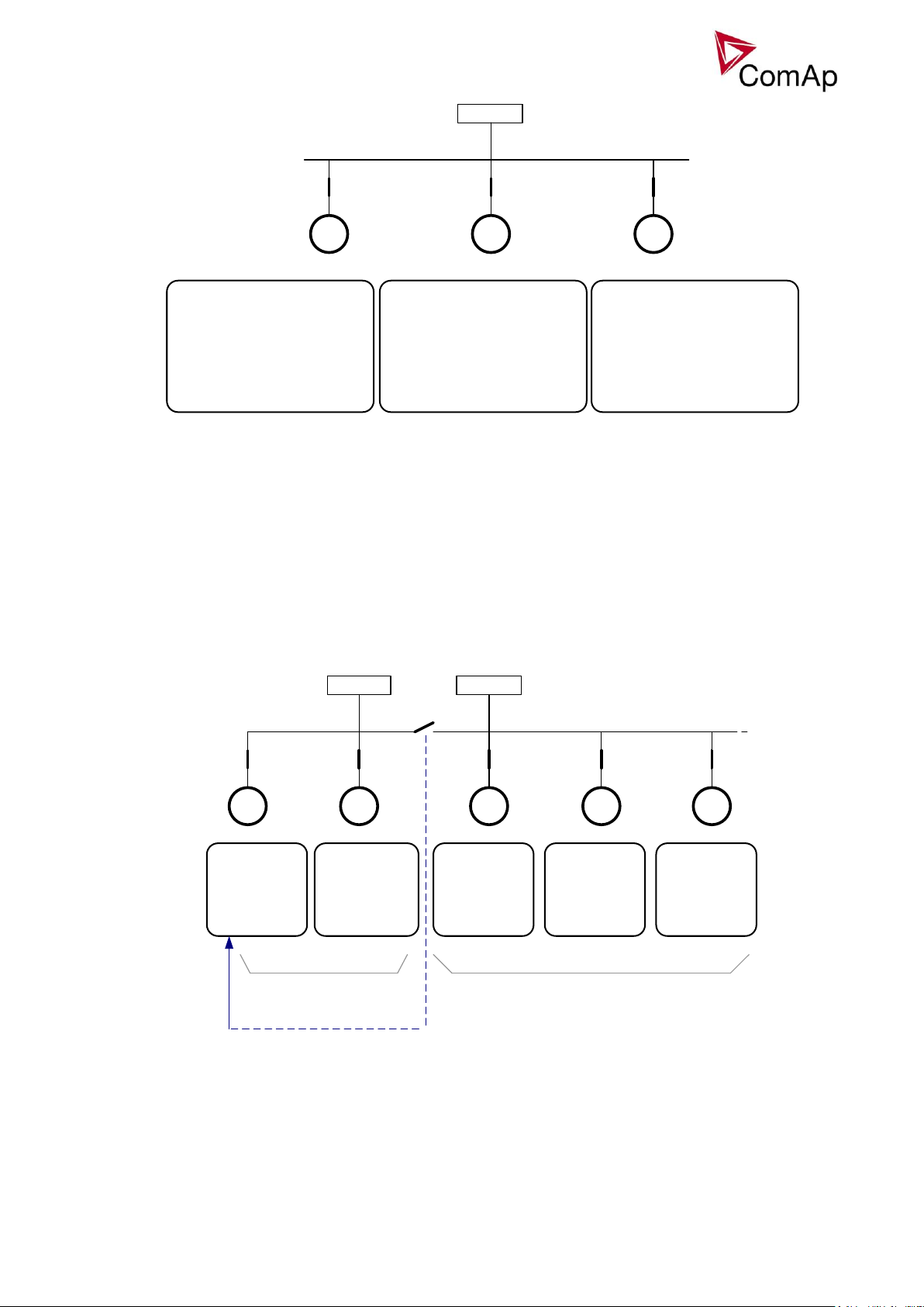
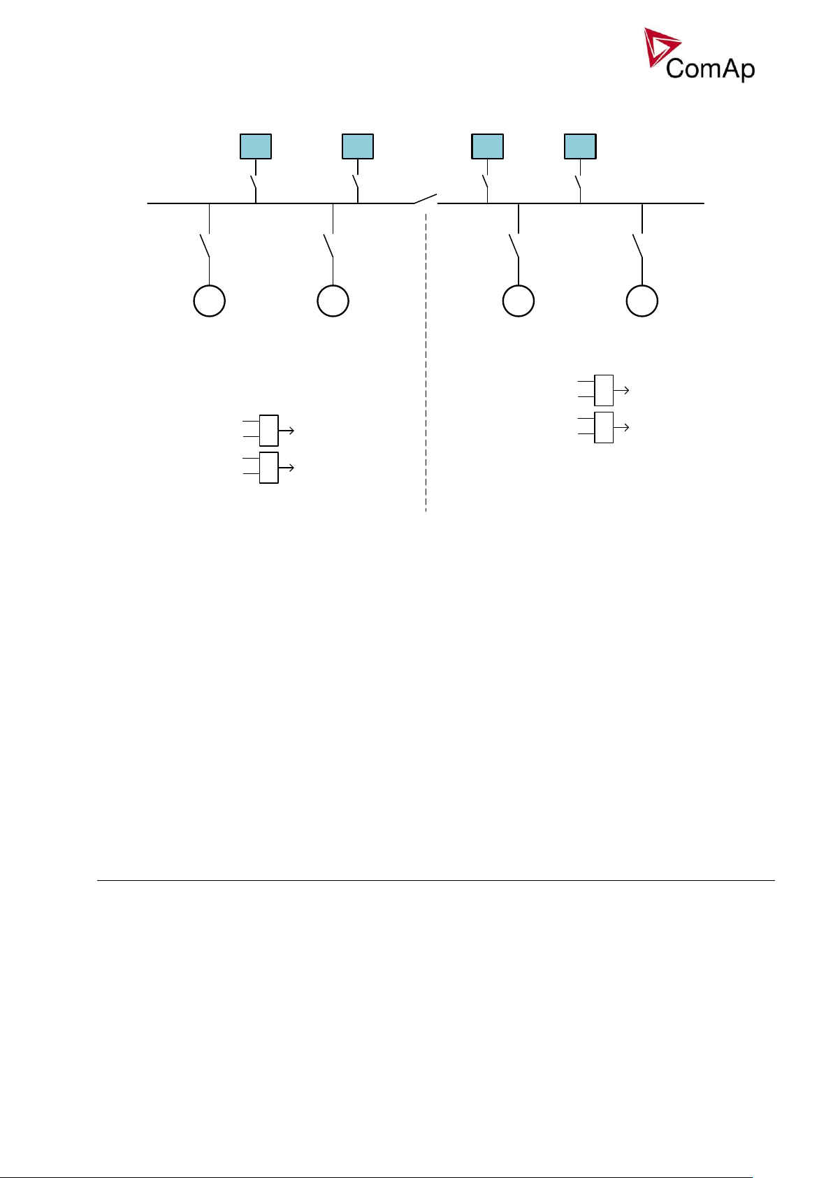
G1 G2 G3 G4 G5
LOAD1 LOAD 2
Basic settings:
Contr.addr = 1
Pwr management:
Control group = 1
GroupLinkLeft = 1
GroupLinkRight = 2
BTB
BI Group link
1.controller
2.controller
3.controller 4.controller 5.controller
Basic settings:
Contr.addr = 2
Pwr management:
Control group = 1
GroupLinkLeft = C
GroupLinkRight = C
Basic settings:
Contr.addr = 3
Pwr management:
Control group = 2
GroupLinkLeft = C
GroupLinkRight = C
Basic settings:
Contr.addr = 4
Pwr management:
Control group = 2
GroupLinkLeft = C
GroupLinkRight = C
Basic settings:
Contr.addr = 5
Pwr management:
Control group = 2
GroupLinkLeft = C
GroupLinkRight = C
Control group 2.
Control group 1.
BTB feedback
Pwr management of splitted group
Important setpoints: Control group, GroupLinkLeft, GroupLinkRight
When a Bus-tie disconnects the gen-set group the Power management and Load and Var share can operate
separately on each of them.
To enable the independent Pwr management, Load and Var sharing between the gensets, group of gensets
splitted by bus tie breaker, configure the setpoints as depicted on this picture.
Inteli NT GeCon-MARINE MINT, SW Version 3.2, ©ComAp – July 2015
IGS-NT-GeCon-MARINE-MINT-3.2.PDF
Page 20
20
CurShedLev
CurRecLev
FreqShedLvl
FreqRecLvl
LdShed stage 1
LdShed stage 2
LdShed stage 10
ManualLdRecon
Load shedding:
Ld Shed delay
Ld recon delay
DeadBusStart function
Function is determined for emergency incident - blackout on the power bus – on the ship.
Function is controlled by this setpoints/signals:
Setpoint:DeadBusStrt [ ENABLED / DISABLED ]
Setpoint:DeadBusST del [ 0…600s ]
LBO: DeadBusStart
Alarm: DeadBusStart
Description:
When controler detects no voltage (any bus phase voltage is below 15 VAC) on the bus for the time
„DeadBusSTdel”, then this function activates local start command, starts the gen-set, and connects it to the
bus.
When the function Dead Bus Start is evaluated, LBO:Dead Bus Start is activated.
When LBO:Dead Bus Start=1 then Power management system is internally DEACTIVATED – all gensets with active LBO:DeadBusStart are started and connected to the bus (and run in loadsharing).
Activation and deactivation of this function is written to the history.
For deactivation of this function is necessary to switch to SEM mode and confirm the DeadBusStart alarm.
DeadBusStart function works in AUT mode only.
Function is available in MINT aplication.
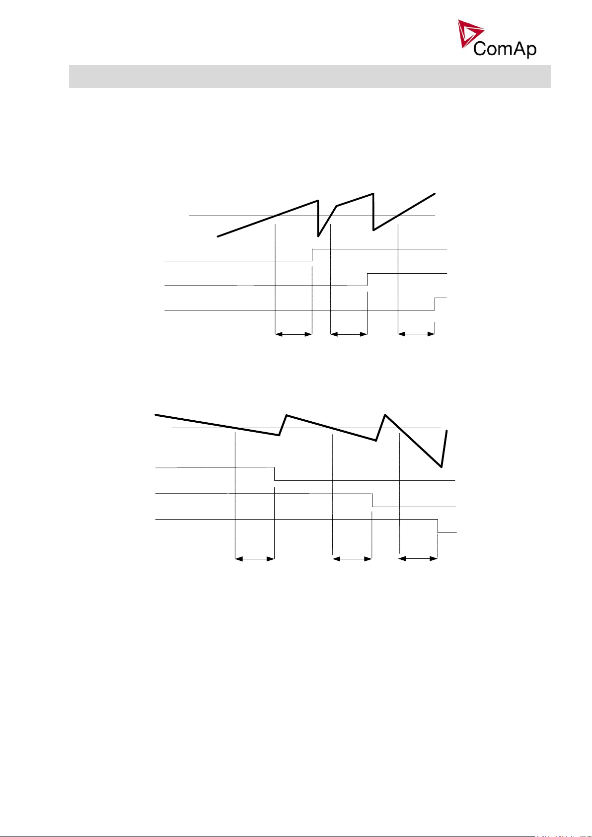
Load shedding
Load shedding fiction is dedicated for tripping of non-essential load in case of high generator current, or drop
of generator frequency above/below preadjusted limits, for preadjusted time.
All LOAD SHED outputs are activated (closed) to trip the unessential load when gen-set goes to island:
a) When GCB is closed after mains fail and gen-set starts in AUT mode.
b) When MCB opens from parallel to mains operation in AUT mode.
c) Before MCB is opened in SEM mode by button.
The load shedding function is active in all controller modes except OFF and MAN.
Load shedding has ten steps and each step is linked with its own Load shed x binary output. The non
essential load shedding is based on generator current and generator frequency. There is only one level for
current load shedding and one level for frequency load shedding for all 10 steps, as well for reconnection
level and delay. Load shed can only move from one step to the next, e.g. No LoadShed to LdShed S1 to
LdShed S2 to LdShed S10 and vice versa.
If manual reconnection of the load is desired, the AutoLd recon setpoint needs to be disabled (AutoLd recon
= DISABLED) and the MAN load recon binary input needs to be configured.
Rising edge on this input resets the controller to a lower stage, but only if the load is under the Ld recon level
at that moment.
The current load shedding can be activated in case any of phase current exceeds the adjusted limit. The
reconnection is able only in case all of the current values are below reconnection level.
Hint:
Inteli NT GeCon-MARINE MINT, SW Version 3.2, ©ComAp – July 2015
IGS-NT-GeCon-MARINE-MINT-3.2.PDF
Page 21
21
Ld shed
del
Ld shed
del
Ld shed
del
BO Load shed 1
BO Load shed 2
BO Load shed 3
Curr shed level
Gen-set current
closed
closed
closed
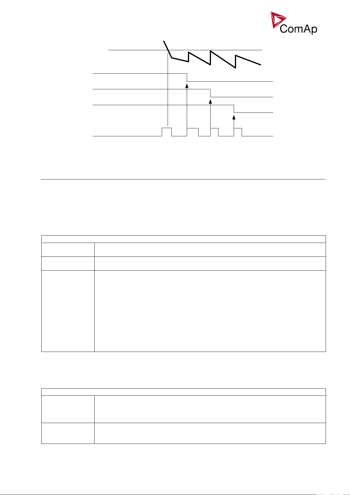
Ld recon del Ld recon delLd recon del
BO Load shed 2
Curr recon level
Gen-set current
BO Load shed 3
BO Load shed 1
opened
opened
opened
If no Load Shedding outputs are configured, there is no record to history and no screen timer indication of
the activity of this function.
On the following pictures, the generator current load shedding is depicted. The current is evaluated from all 3
phases, each phase can activate the load shedding. On the picture, due to transparency, only 3 load shed
outputs are depicted, not all 10.
The generator frequency based load shedding is in fact the same, but fall below preadjusted limit is watched,
instead of exceeding of the limit as in case of current load shedding.
Load reconnection – automatic -> AutoLd recon = ENABLED
Load reconnection – manual -> AutoLd recon = DISABLED
Inteli NT GeCon-MARINE MINT, SW Version 3.2, ©ComAp – July 2015
IGS-NT-GeCon-MARINE-MINT-3.2.PDF
Page 22
22
BO Load shed 2
Curr recon level
BO Load shed 3
BO Load shed 1
BI Man load recon
opened
opened
opened
no action
Gen-set current
ProcCrtlMulti: Reg kW/kVAr
STD
Standard isochronous Load Sharing and VAr Sharing are based on CAN
intercontroller communication.
DROOP
Load Sharing and VAr Sharing regulations are based on droop. Requested power of
each gen-set is calculated based on bus voltage and bus frequency.
EMERG DROOP
Load Sharing and VAr Sharing regulation are based on standard CAN intercontroller
communication, but can be conditionally switched to droop. All controllers are
continually checking the CAN16/CAN32 register (value in group “Info”) to see witch
addresses are they in cooperation (use the LBI EmergDroopEnab to confirm the
supervised constalation of addresses on CAN). In case of lost of any controller from
CAN the regulations are automatically switched to droop (yellow alarm EmergDroop
act appears in alarm list, message EmergDROOPon is writen in history). Load Sharing
and VAr Sharing regulation are switched back to the standard mode 60 s after the
constalation of addresses on CAN returns back to the original state (message
EmergDROOPoff is written in history, alarm EmergDroop act has to be confirmed
manually). The purpose of this function is protection against the cut off the CAN
intercontroller line.
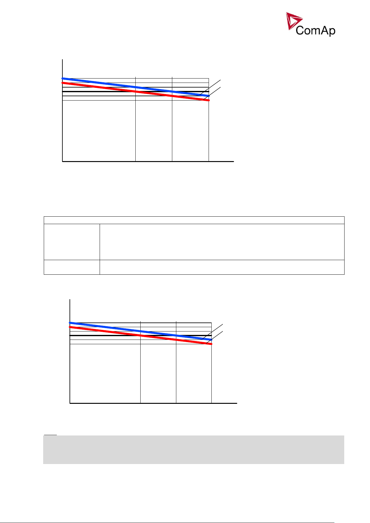
Sync/load ctrl: Load droop, LdDroopOffset
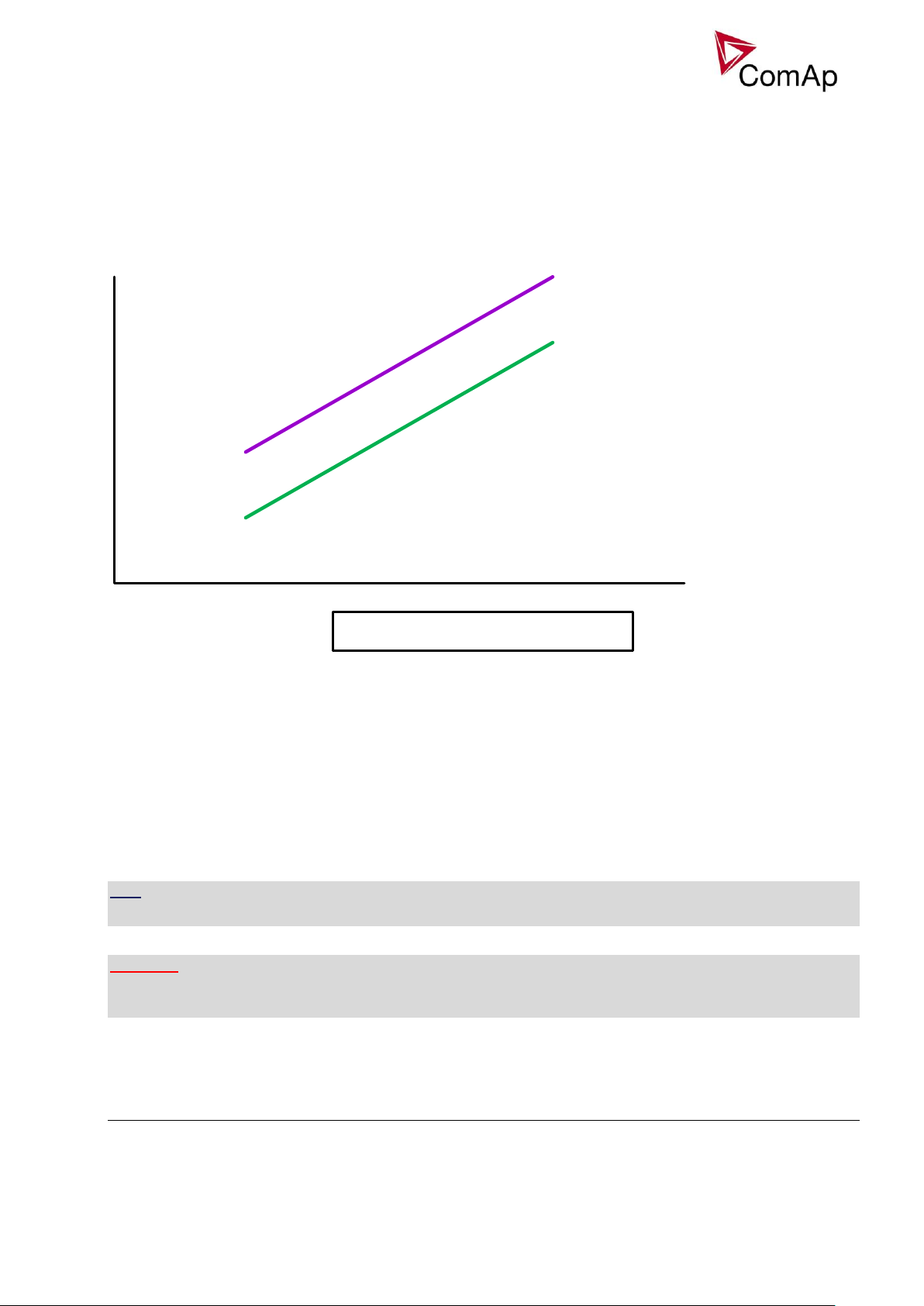
Load droop
This setpoint defines the slope of the load droop correlation. The slope is set as a
droop of frequency in percentages of the requested frequency (Basic settings:
Nominal freq + Nom frq offset) on the range of the requested power from 0 to 100% of
Basic settings: Nomin power.
LdDroopOffset
This setpoint defines the value of requested power on the requested frequency (Basic
settings: Nominal freq + Nom frq offset). Allows to shift the droop correlation line up
or down.
DROOP
The droop regulation of kW/kVAr is the alternative to the isochronous Load Sharing and VAr Sharing. In the
isochronous regulation are all information about the kW/kVAr shared via intercontroller communication line
whereas in droop no intercontroller communication is needed. The droop regulation is based on voltage and
frequency which are measured on the common bus. The requested kW/kVAr are calculated in each
controller from the actual bus voltage and bus frequency. This principle of regulation needs the voltage and
frequency beeing changing within defined limits. Type of regulation depends on settings of setpoint
ProcCrtlMulti: Reg kW/kVAr.
Load Sharing in droop
Characteristics of Load Sharing in droop are given by settings of these parameters:
Inteli NT GeCon-MARINE MINT, SW Version 3.2, ©ComAp – July 2015
IGS-NT-GeCon-MARINE-MINT-3.2.PDF
Page 23
23
50%
Preq
50Hz
49Hz
Load droop = 4% ˜ 2 Hz (1% ˜ 0,5 Hz)
51Hz
75% 100%
f
LdDroopOffset = 75%
LdDroopOffset = 50%
Nomin power
Sync/load ctrl: VAr droop, VArDroopOffset
VAr droop
This setpoint defines the slope of the VAr droop correlation. The slope is set as a
droop of voltage in percentages of the generator nominal voltage (Basic settings:
GenNomV) on the range of the requested reactive power from 0 to 100% of nominal
reactive power (value of nominal reactive power is not given by setpoint but it is
calculated from setpoint Nomin power whilst the PF=0,8).
VArDroopOffset
This setpoint defines the value of requested reactive power on the nominal voltage
(Basic settings: GenNomV). Allows to shift the droop correlation line up or down.
50%
Qreq
230,0 V
225,4 V
VAr droop = 4% ˜ 9,2 V (1% ˜ 2,3 V)
234,6 V
75% 100%
V
VArDroopOffset = 75%
VArDroopOffset = 50%
Nomin reactive power
Example: Load droop = 4%, LdDroopOffset = 50% (75%)
VAr Sharing in droop
Characteristics of VAr Sharing in droop are given by settings of these parameters:
Example: VAr droop = 4%, VArDroopOffset = 50% (75%)
Hint:
Droop mode allows cooperation of gen-set equipped by ComAp control system with gen-set equipped by any
third party control system. The steady bus voltage and bus frequency has to be regulated by this third party
control system. Active and reactive power of gen-set equipped by ComAp controller is kept on values given
by droop settings.
Inteli NT GeCon-MARINE MINT, SW Version 3.2, ©ComAp – July 2015
IGS-NT-GeCon-MARINE-MINT-3.2.PDF
Page 24

24
Note:
Over frequency and under frequency protections are active in droop. Be aware that the gen-set frequency in
droop can cross the levels of these protections. The force value on the under/over frequency protection limits
can be used if it is needed to set the different limits in droop.
Protection mode settings
Protections in this application are affected by Setpoint ProtectionMode (group ProcessControl).
This setpoint is active in MAN,SEM and AUT mode.
Setpoint ProtectionMode has 2 options of settings:
ACTIVE:
Standard setting – all protections are active, in case of 2nd level alarm the breaker is opened/controlled.
(2-nd level alarms are evaluated, GCB or MCB is controlled)
NOT ACTIVE:
2-nd level alarms are evaluated only , but GCB or MCB are NOT opened (no actions).
Exceptions are Emergency Stop and Sd override alarms type.
External breaker control
This application accepts external breaker control in these situations:
MINT application:
Mode:MAN, SEM
External breaker control is accepted only when LBI:ReadyToLoad=1.
Exceptions:
If the BUS voltage is >15V and GCBfdb=1 and LBI:ReadyToLoad=0 then BO GCB Fail and History
record are performed.
SPtM application:
Mode:SEM
External MCB control is accepted
External GCB control is accepted only when LBI:ReadyToLoad=1.
Exceptions:
If the Mains parameters are out of limits (voltage and frequency) and GCB and MCB are closed
and LBI:ReadyToLoad=1 – external control is not accepted – Wrn MCB fail and Wrn GCB fail are
evaluated.
If the Mains voltage is > 15V and MCBfdb=1 and GCBfdb=1 and LBI:ReadyToLoad=0 then BO
GCB Fail and History record are performed.
SPI application:
Mode: SEM
External GCB control is accepted only when LBI:ReadyToLoad=1.
Exceptions:
Inteli NT GeCon-MARINE MINT, SW Version 3.2, ©ComAp – July 2015
IGS-NT-GeCon-MARINE-MINT-3.2.PDF
Page 25

25
If the Mains parameters are out of limits (voltage and frequency) and GCB and MCB are closed
and LBI:ReadyToLoad=1 – external control is not accepted – Wrn MCB fail and Wrn GCB fail are
evaluated.
If the Mains voltage is > 15V and MCBfdb=1 and GCBfdb=1 and LBI:ReadyToLoad=0 then BO
GCB Fail and History record are performed.
Heavy consumers support
On ship are ussualy several heavy consumers which are connected to power bus only for limited
time. Before connecting is necessary to start more genset or easily increase actual load reserve for
covering the connection of heavy consumer.
Defining sizes of Heavy consumers:
Group: HeavyConsumers
Setpoints: HeavyConsumer1..6
Request before connection of Heavy consumer:
LBI: HeavyConsumer1 (request for increasing load reserve before Heavy consumer connection)
Confirmation/feedback for Heavy consumer connection
LBO: HeavyCons fdb1 (after activation the Heavy consumer connection is possible)
How it works:
1) Before Heavy consumer connection – the request is activated (LBI: HeavyConsumer1)
2) When LBI: HeavyConsumer1 is activated then size of consumer (Setpoints:
HeavyConsumer1) is added to actual load reserve.
3) When the load reserve is increased (Syst res OK is activated) then HeavyCons fdb1 is
activated.
4) Based on the HeavyCons fdb1=1 the user can connect HeavyConsumer1 to bus.
CAUTION!
The user must ensure that each heavy consumer will have the same size over all controllers (it means that
HeavyConsumer1 has the size in controller #1 and #2.) (these setpoints are not shared)
Each controller counts level for start and stop (in power management system) locally, so user must ensure
correct activation of Heavy consumer inputs in all controllers (for example via Share Inputs/Outputs).
Solution is shown on the picture:
Inteli NT GeCon-MARINE MINT, SW Version 3.2, ©ComAp – July 2015
IGS-NT-GeCon-MARINE-MINT-3.2.PDF
Page 26
26
G1 G2 G3 G4
1 2 3 4
Control group 1 Control group 2
BTB
SHBIN
SHBI1:HeavyCons 1 -> LBI: HeavyConsumer1
SHBI2:HeavyCons 2 -> LBI: HeavyConsumer2
SHBI3:HeavyCons 3
&
SHBI5:BTBfeedback
LBI:HeavyConsumer3
SHBI4:HeavyCons 4
&
SHBI5:BTBfeedback
LBI:HeavyConsumer4
SHBIN
SHBI3:HeavyCons 3 -> LBI: HeavyConsumer3
SHBI4:HeavyCons 4 -> LBI: HeavyConsumer4
SHBI1:HeavyCons 1
&
SHBI5:BTBfeedback
LBI:HeavyConsumer1
SHBI2:HeavyCons 2
&
SHBI5:BTBfeedback
LBI:HeavyConsumer2
Heavy
Consumer
Heavy
Consumer
Heavy
Consumer
Heavy
Consumer
Two kinds of Heavy consumers:
Bow thruster
After connection of bow thruster to the bus it can be loaded from 0-100% variously acording to the
current maneuvers of ship.
In this case the request (increasing of actual Load reserve) must stay active (LBI:
HeavyConsumer1=1) all the time during connection of bow thruster to bus
Compressor
Compressor usually work ON/OFF (with unchanging load)
So after connection of compressor to the bus (and its activation) the load of Compressor is added
to current load on the bus and the user can deactivated the request (LBI: HeavyConsumer1->0),
because compressor has stable load which was currently connected.
Variable speed support
This fw contains variable speed support which is used on Hybrid ship (ship with DC bus).
Variable speed control is usually used on ship where the gen-sets work in long term period on
small load. By changing speed on genset is possible to achieve lower fuel consumption.
Frequency (and Voltage) are usually control according to current load.
For variable speed is used:
Setpoints:
Nominal freq 30..65 Hz (step 1 Hz) FV (Basic settings Group)
Inteli NT GeCon-MARINE MINT, SW Version 3.2, ©ComAp – July 2015
IGS-NT-GeCon-MARINE-MINT-3.2.PDF
Page 27
27
ForceBlock6Del 0-60s (step 0,1s) FV (Delays/Timers Group)
30Hz
50Hz
138V
230V
voltage
frequency
Magnetic flux =U/f ~konstant
GenNomV, BusNomV FV (Basic settings Group)
Voltage dependence on frequency
In generator is induced magnetic flux, which is almost constant in various RPM.
It is necessary to change nominal frequency together with nominal voltage – due to their
dependence.
Temporary blocking of fix frequency and voltage protections
Temporary blocking of frequency and voltage fix protections
After submitting a request for change of nominal frequency and voltage the generator needs some
time for performing the changes. During this time the fix frequency and voltage protections
(connected to nominal values) must be blocked.
The time need for blocking of these protections is set by setpoint:
ForceBlock6Del 0-60s (step 0,1s) FV (Delays/Timers Group)
HINT
With larger frequency range the regulation can be rougher, in this case the AC/DC inverter is expected.
WARNING!
Used generator should be designed for variable rotation.
With frequency changes the nominal value of Voltage must be also changed.
Force value – step by step guide
In this chapter there is complete step by step guide which shows how to use Force value function of the
controller.
Inteli NT GeCon-MARINE MINT, SW Version 3.2, ©ComAp – July 2015
IGS-NT-GeCon-MARINE-MINT-3.2.PDF
Page 28
28
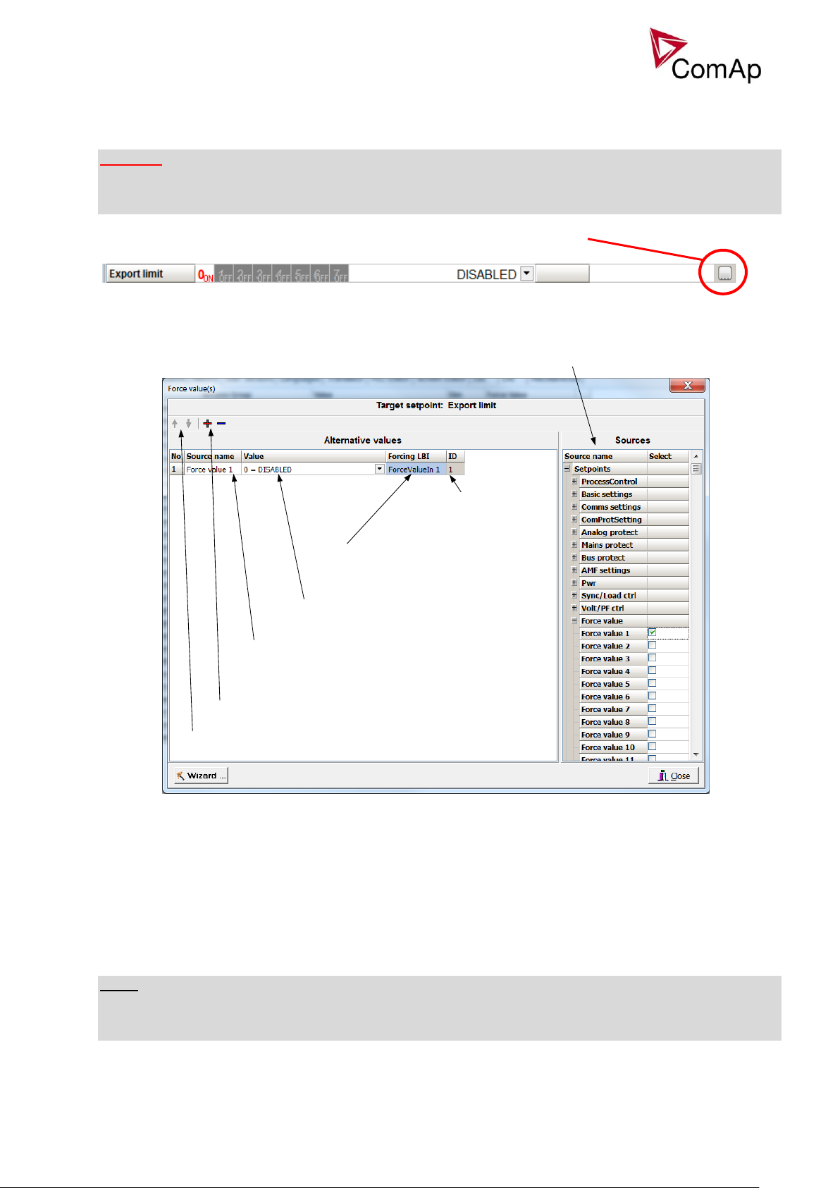
Add or remove Force value
Change position of Force value functions (priority)
Change the name of the source setpoint
(available only for Force value 1-16 setpoints)
Select the value that should be forced (i.e.
the value of the particular setpoint)
Rename binary input that
triggers the forcing
ID of binary input
(1 for ForceValueIn 1 etc.)
Select source setpoint or value
Forcing of values is used to change particular setpoint temporarily by activation of related Binary Input. This
is used to change function of controller under given conditions (e.g. there are two different periods during the
day when Export limit given by distribution network is required or not).
WARNING!
Setpoints must not be written continuously (e.g. via Modbus connection)! If continuous change of setpoints
is required, combination of External values and Force value function needs to be used. The memory that
holds setpoints is designed for up to 105 writings. Than memory may be damaged!
Setpoints that are available for forcing may be identified by Force value button on the right side in GenConfig
(see the figure below).
When the button is clicked, Force value dialog appears.
For example if we add Force value:Force value 1 to be forced to ProcessControl:Export limit as value 0
(DISABLED) by Binary Input FORCEVALUEIN 1 we can change the function of Export limit from ENABLED to
DISABLED by activation of FORCEVALUEIN 1. It is possible to rename the setpoint to e.g.
Force value:ExportDisabled and Binary Input as well to e.g. DISABLEEXPLIM. The function will not change
(only the corresponding names).
It is possible to use several force value functions for one setpoint. If more than one forcing Binary Input is
active, the one with the highest position (lowest number in the Force value dialog) is used.
It is possible as well to use one Binary Input to force multiple setpoints (e.g. in case of complex function
change).
NOTE:
It is possible only to force value or setpoint in other setpoint if their dimension and range are the same (e.g.
only value with dimension in hours and which is Integer 16 to a setpoint with dimension hours and which is
as well Integer 16). You may use PLC block Convert to change the dimension and range if needed.
Inteli NT GeCon-MARINE MINT, SW Version 3.2, ©ComAp – July 2015
IGS-NT-GeCon-MARINE-MINT-3.2.PDF
Page 29
29
Values for continuous writing from external sources
This function is especially designed for continuous writing of setpoints from external sources (e.g. via
Modbus connection).
WARNING!
Setpoints must not be written continuously (e.g. via Modbus connection)! If continuous change of setpoints
is required, combination of External values and Force value function needs to be used. The memory that
holds setpoints is designed for up to 105 writings. Than memory may be damaged!
It is possible to use up to four different External values for continuous writing from external sources. The
values are adjusted by setpoints in Force value group. Default (also initial) value may be adjusted, rate of
change of ExtValueX (by Binary Inputs EXTVALUEX UP and EXTVALUEX DOWN) can be adjusted as well as
high and low limit of the value.
There are two way, how to adjust External values. One is using Binary Inputs mentioned above. Second one
is to write the value directly using e.g. Modbus. External values then may be converted using PLC block
convert and force into setpoint which is then continuously forced (note: NOT WRITTEN) by the value of
ExtValueX. This way internal memory is safe and no damage may occur.
External values are reverted back to their default (initial) value (given by corresponding setpoint) when
Binary Input for their reset is active (and they change to the previous value after Binary Input deactivates).
When the Binary Input is active the External value cannot be changed by Modbus writing or by using Binary
Inputs for up and down value.
NOTE:
External values are not available for external writing when any Binary Input (up, down or reset) related to
them is active.
Note also that when the controller is reset (powered down and up again), all external values are reverted
back to their default (initial) values.
HINT
For information on how to write (or read) objects from controller via Modbus, please refer to the latest
Communication guide for InteliGen and InteliSys.
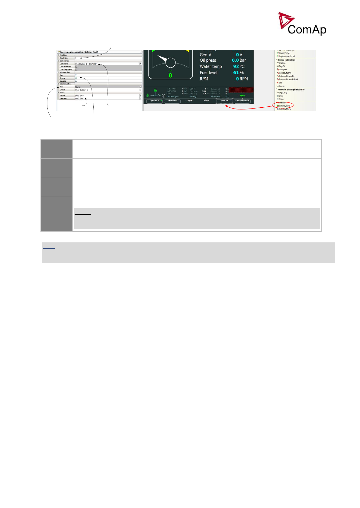
User Buttons
There are several User Buttons available in the controller. It is possible to set them on Soft Buttons in
InteliVision 5 or 8.
Inteli NT GeCon-MARINE MINT, SW Version 3.2, ©ComAp – July 2015
IGS-NT-GeCon-MARINE-MINT-3.2.PDF
Page 30
30
Selects which button is this function mapped to
(0 – first button, 1 – second button and so on)
Choose UserButton index and
its function (ON/OFF etc.)
Choose which colour will be
available for this button
Select which condition triggers
which coulour
Adjust text for the button
when it is active or inactive
ON
Pressing the button changes the state of log. Binary Output USER BUTTON X to closed.
When the output is closed and the button is pressed state is not changed.
OFF
Pressing the button changes the state of log. Binary Output USER BUTTON X to opened.
When the output is opened and the button is pressed state is not changed.
ON/OFF
Pressing the button changes the state of log. Binary Output USER BUTTON X to opened or
closed depending on previous state (it is changed to the opposite state).
PULSE ON
Pressing the button issues log. Binary Output USER BUTTON X to close for one second.
NOTE:
Repeated pressing of button during the closed period (one second) causes issuing other
puls of length of one second to be generated from the moment of button pushing.
Available functions for soft buttons are listed in the following table.
HINT
It is possible to lock User Button with password (go to tab Commands in GenConfig). User Buttons 1-5, 6-8
and 9-16 can be locked separately. It is also possible to use User Buttons in SCADA diagrams.
User Mask function
In GenConfig you can easily set any object in Screen Editor to show or hide based on activation of particular
Logical Binary Input available for users. Below, there is diagram showing the setup of User Mask function in
Screen Editor.
Inteli NT GeCon-MARINE MINT, SW Version 3.2, ©ComAp – July 2015
IGS-NT-GeCon-MARINE-MINT-3.2.PDF
Page 31

31
Select the proper function
Show = appears when LBI gets active
Hide = disappears when LBI gets active
None = no function
Select the object
Select which User Mask is used for
this object
NOTE:
Masking of screens in InteliVision 5 supports only Show function
Use also other masking functions (masking can react on several internal states, e.g. activation of Timers).
Remote Control Function
It is possible to remotely control several Binary Outputs in the controller. You can either use Remote
Switches tool in InteliMonitor (select Remote switches in menu for corresponding controller), import Remote
Switches tool to a SCADA diagram in Line Diagram Editor or use external device via Modbus (register
#46361 and command #26 (1A hex), for more information on Modbus please refer to the InteliGen/InteliSys
Communication guide).
Remote Switch will activate or deactivate depending on remote control so it can be used to manually control
devices, simulate malfunctions while commissioning etc.
Figure: Remote Switches tool in InteliMonitor, Remote Switches tools in Line Diagram Editor and Mobus commands
Inteli NT GeCon-MARINE MINT, SW Version 3.2, ©ComAp – July 2015
IGS-NT-GeCon-MARINE-MINT-3.2.PDF
Page 32

32
LBO:RemoteControl1 LBI:Emerg. manual
Remote Switch
command
Vitual Output
Virtual Input
1
2
3
4
5
6
7
8
VPIO module
Remote Switches may be easily used to trigger logical Binary Input function and all other related functions as
normal switch on Binary Input. Module VPIO (Virtual Peripheral Inputs- Outputs) can be added to
configuration and it will copy the state of Remote Switch on virtual output to its counterpart virtual input.
Refer to the figure below for example.
Virtual Peripheral Inputs-Outputs (VPIO) module
For the controller there are several modules available. One of them is Virtual Peripheral Inputs-Outputs
module which is particularly usefull for connection of logical Binary Output functions to logical Binary Input
functions. This way internal controller function may easily trigger other internal controller functions without
unnecessary wiring or usage of PLC functions.
Module is functioning the same way as normal module with 8 outputs and 8 inputs, but the difference is, that
each input copies its counterpart output. It is possible to select any logical Binary Output function for one of
the outputs of VPIO module. Inputs on VPIO module work the same way as standard input of the controller
(i.e. it can be assigned function and protection).
For example of this function please refer to the chapter Remote Control function.
Shared Inputs and Outputs
It is possible to share Binary and Analog values between all the controllers via CAN bus, thus saving
physical Inputs and Outputs and excess wiring.
Figure: Using of Remote Switches to trigger logical binary inputs
Inteli NT GeCon-MARINE MINT, SW Version 3.2, ©ComAp – July 2015
IGS-NT-GeCon-MARINE-MINT-3.2.PDF
Page 33

33
SHBOUT (1) SHBIN (1)
SHBOUT (2)
Not Received
Module SHBIN (2) is not
inserted
SHBOUT (3)SHBIN (3)
SHBIN (2)
Not Received
Module SHBIN (3) is not
inserted
Not Received
Module SHBIN (1) is not
inserted
CAN
CAN
Controller 1 Controller 2
Controller 3
Shared Binary Inputs and Outputs may be used exactly in the same way as standard physical Inputs and
Outputs. If SHBIN or SHAIN modules are configured, at least one corresponding module of SHBOUT or
SHAOUT (respectively) is needed. If it is not configured, corresponding protection appears because SHBIN
or SHAIN will be missing. See the figure below for more information.
CAUTION!
For proper function of Shared Binary and Analog Inputs and Outputs, only one source of Shared Binary or
Analog Outputs must be configured (i.e. it is not possible to configure in one controller SHBOUT1 and to
another one as well SHBOUT1).
HINT
Controller sends Shared Binary Outputs each 100ms if there are any changes in any bit position. If there are
no changes, controller sends the information with period 1s.
Figure: Adding of various modules
Figure: Principal Scheme (same for shared Binary I/O and shared Analogue I/O
Inteli NT GeCon-MARINE MINT, SW Version 3.2, ©ComAp – July 2015
IGS-NT-GeCon-MARINE-MINT-3.2.PDF
Page 34

34
SHBIN (1)
SHBOUT (2)
Not Received
Module SHBIN (2) is not
inserted
SHBOUT (3)SHBIN (3)
CAN
Controller 2
Controller 3
Not Transimitted
Module SHBOUT (1) is not
inserted
Level 1, Level 2 or no protection is displayed
DISTBOUT
DISTBIN
-01
DISTBIN
-02
DISTBIN
-03
DISTBIN
-04
Controller CAN 1
DISTBOUT
DISTBIN
-01
DISTBIN
-02
DISTBIN
-03
DISTBIN
-04
Controller CAN 2
DISTBOUT
DISTBIN
-01
DISTBIN
-02
DISTBIN
-03
DISTBIN
-04
Controller CAN 3
DISTBOUT
DISTBIN
-01
DISTBIN
-02
DISTBIN
-03
DISTBIN
-04
Controller CAN 4
CAN communication
Distributed Binary Inputs and Outputs
It is possible to share Binary and Analog values between all the controllers via CAN bus, thus saving
physical Inputs and Outputs and excess wiring.
DISTBIN and DISTBOUT work in a different way than SHBIN and SHBOUT. Each controller has one pack of
eight DISTBOUT available (if not configured or no function is assigned to any output, it does not broadcast
them). The number of DISTBOUT module is not shown in the configuration and it is always corresponding to
the CAN address of the controller (e.g. the controller with address 5 will be broadcasting DISTBOUT-05
which can be received if module DISTBIN-05 is configured in another controller. Up to 32 DISTBIN modules
can be configured (meaning that the controller will be receiving all DISTBOUT from all the controller, even
his own).
It is not possible to change the name of DISTBIN inputs or add protections.
In the example below you can see 4 controllers with various DISTBIN and DISTBOUT configuration.
NOTE:
HINT
Controller sends Distributed Binary Outputs each 100ms if there are any changes in any bit position. If there
are no changes, controller sends the information with period 1s.
NOTE:
DISTBIN and DISTBOUT function is not available for IM-NT-GC and IG-NT(C)-GC controller.
NOTE:
DISTBIN and DISTBOUT function is conditioned by IGS-NT-LSM+PMS dongle.
Inteli NT GeCon-MARINE MINT, SW Version 3.2, ©ComAp – July 2015
IGS-NT-GeCon-MARINE-MINT-3.2.PDF
Page 35

35
Modbus Reading and Writing
User Modbus register number
Standard Modbus register number
Communication object number
Value, Setpoint, Alarm state
Select type
Select object
Controller supports Modbus Slave functions (an external device may write or read from a controller). Modbus
registers corresponding to objects in the controller can be exported to text form in GenConfig.
Figure: Exporting of Modbus registers
If Modbus Master function is required extension module I-CB/Modbus connected via CAN1 can be used. For
more information on how to use this module please refer to InteliGen/InteliSys Communication Guide and to
I-CBEdit manual.
User MODBUS
Users can define Modbus registers from 42873 to 43000. Values, setpoints and Alarm states can be
specified for these new Modbus registers to prepare the Modbus protocol for batch reading and writing or to
standardize Modbus protocol between FW versions or branches.
NOTE:
User MODBUS function is not available for IM-NT-GC controller.
Inteli NT GeCon-MARINE MINT, SW Version 3.2, ©ComAp – July 2015
IGS-NT-GeCon-MARINE-MINT-3.2.PDF
Page 36

36
Modbus Switches
Register for writing
Modbus register number
Value for back-reading
Modbus register number
ModbusSw1
46337
ModbusSw1
40547
ModbusSw2
46338
ModbusSw2
40548
Register port for writing
Input value
LBO ModbusSw16 ………………….ModbusSw1
ModbusSw1 (46337)
000F HEX
0000 0000 0000 1111
Register port for writing
Input value
LBO ModbusSw32 ………………….ModbusSw17
ModbusSw2 (46338)
F000 HEX
1111 0000 0000 0000
Group
PLC Block
IS-NT-GeCon
MARINE
3.2
IG-NT-GeCon
MARINE
3.2
The “Modbus Switches” contains of two groups of LBOs named “ModbusSw1” and “ModbusSw2”. Both
registers are available on Modbus for simple writing (using command 6 or 16). The particular bits of these
registers are available as binary status for universal use in logical binary outputs of the controller as
“ModbusSw1..ModbusSw32”. No password is required for writing of those registers. There are two Values
“ModbusSw1” and “ModbusSw2” in group “Log Bout” available for back-reading.
NOTE:
The LSB of ModbusSw1 (46337) corresponds with LBO “ModbusSw1”
The LSB of ModbusSw2 (46338) corresponds with LBO “ModbusSw17”
The Values ModbusSw1 and ModbusSw2 have the position of LSB opposite-wise.
Examples:
Power Formats
IGS-NT family allows user to choose from several Power Formats that affect dimensions in which values and
some setpoints are interpreted or adjusted. Power formats may be changed in Miscellaneous tab in
GenConfig. There are following Power Formats available:
1 kW kVAr kVA kX V
0,1 kW kVAr kVA kX V
0,01 MW MVAr MVA MX kV
0,01 MW MVAr MVA MX V
NOTE:
Range of some setpoints and values is changed significantly when different Power Formats are selected.
Last Power Format is designed to be used in combined Power/High Voltage and Low Voltage instalations.
High voltage is then interpreted in Volts (e.g. 33256V instead of 33kV).
Last two Power Formats can be used in combination on one CAN bus.
PLC functions
Following functions are available in IGS-NT-GeCon-MARINE firmware.
Inteli NT GeCon-MARINE MINT, SW Version 3.2, ©ComAp – July 2015
IGS-NT-GeCon-MARINE-MINT-3.2.PDF
Page 37

37
Logical function
OR/AND
128
32
XOR/RS
128
32
Comparators
Comp Hyst
16
4
Comp Time
16
4
Comp Win
16
4
Math operations
Math Fc
16
2
Ext Math Fc 8 2
Interp. Fc’B’ 8 1
Math AxB/C 4
Regulators
PID Ana B 4 2
PID Bin 4 2
Ramp functions
Ramp 4 2
Up/Down 4 2
Inc/Dec 2 2
Mov Avg 2 1
Time functions
Timer 4 1
Delay
16
Delay „B“
8
8
Others
Ana Switch
16
2
Force Hist 4 4
Force Prot 4 4
Jump 4 4
Mux Const. 4 4
Counter 4 1
Decomp 4 4
Convert
10
10
Multi language support
NT Family controllers support up to three Languages that is possible to switch during controller duty. Every
terminal (i.e. Remote display or PC-InteliMonitor) can be switched to different language. Use PC-GenConfig
- Translator tool to translate texts to another language.
Default application archives contain all texts in English only.
ECU interface customizing
The list of available ECU interfaces can be found in GenConfig / Modules / ECU list.
In sw GeCon is possible to configure the any ECU communicating via J1939, but controller can read
information only. Writing any information is not possible. ECUs comunicate via modbus are not supported.
Volt/PF control adjustment
IG-AVRi output connection
Every time refer to corresponding AVR manual before interface connecting. Use no droop AVR.
IG-AVRi-TRANS (AC power supply for AVRi) has to be supplied from gen-set voltage.
AVRi outputs can be connected as symmetrical: OUT1-OUT2 or unsymmetrical OUT1-OCOM or OUT2OCOM.
Potentiometer on the AVRi defines maximal OUT1, OUT2 voltage range.
Use symmetrical (OUT1,OUT2) AVRi output to connect the AVRi to AVR auxiliary voltage input.
Inteli NT GeCon-MARINE MINT, SW Version 3.2, ©ComAp – July 2015
IGS-NT-GeCon-MARINE-MINT-3.2.PDF
Page 38

38
100.0 %
10 V
0 V
AVR DCout bias
0 %
A
V
R
i
p
o
t
s
e
t
t
o
m
i
n
i
m
u
m
2 V
A
V
R
i
p
o
t
s
e
t
t
o
m
a
x
i
m
u
m
OUT1 – OCOM [V]
100.0 %
10 V
0 V
AVR DCout bias
0 %
A
V
R
i
p
o
t
s
e
t
t
o
m
i
n
i
m
u
m
2 V
A
V
R
i
p
o
t
s
e
t
t
o
m
a
x
i
m
u
m
OUT2 – OCOM [V]
[V]
100.0 %
A
V
R
i
p
o
t
=
m
a
x
i
m
u
m
AVR DCout bias
10 V
Out1 to Out2
0 V
0 %
-10 V
A
V
R
i
p
o
t
=
m
i
n
i
m
u
m
50 %
AVRi output voltage
Out1 - OCOM
Out2 - OCOM
Out1 – Out2
Bias \ Pot
Min
Max
Min
Max
Min
Max
0 %
0 0 2
10
- 2 V
-10 V
50 %
1 5 1 5 0 V
0 V
100 %
2
10 0 0
+ 2 V
10 V
Use unsymmetrical output if an external AVR potentiometer has to be replaced with AVRi.
AVRi output voltage should change generator voltage typically in range 10 % of Nominal voltage.
For more details please refer to Installation guide – chapter AVR interface examples.
AVRi Out1 or Out 2 to GND output voltage depends on AVRi trim setting
AVRi Out1 to Out 2 output voltage
Voltage control adjustment
HINT:
To judge optimal adjusting induce generator voltage jumps by AVR DCout bias change or by Nominal
voltage change .
AVRi output OCOM is common output. GND was used instead of OCOM
PF control adjustment
The genset should be cca 30 % loaded in parallel to mains and baseload mode.
1) Set the same values PF gain, PF int as in voltage control loop.
2) Set Process control: #SysLdCtrl PtM = BASELOAD, #SysBaseLoad = 30 % of Nominal load,
#SysPFCtrl PtM = BASEPF, #SysPwrFactor = 1.0.
3) Start and synchronize the gen-set in MAN Mode by pressing GCB ON/OFF
4) When running in parallel 30% loaded increase slowly PF gain to unstable point and then decrease
value by 30 % to insure stable performance.
5) Adjust PF int (usually setting to 100% gives optimal performance).
Inteli NT GeCon-MARINE MINT, SW Version 3.2, ©ComAp – July 2015
IGS-NT-GeCon-MARINE-MINT-3.2.PDF
1) Set Voltage gain, Voltage int to zero and AVR DCout bias to 50%.
2) Start always with AVRi pot min adjustment (fully counterclockwise).
3) Start the gen-set in MAN Mode to nominal speed, without load.
4) Adjust generator voltage to nominal value by the potentiometer present on the AVR. If there is no
potentiometer on the AVR, use AVR DCout bias to adjust the nominal voltage.
5) Change AVR DCout bias to 0% and 100% to check generator voltage control range (typically 10
% of nominal voltage). Adjust voltage control range by AVRi trim.
6) Set AVR DCout bias to be Nominal voltage on generator (50%).
7) When gen-set is running unloaded increase carefully Voltage gain to unstable point and then
decrease value by 30 % to insure stable performance.
8) Adjust Voltage int (usually setting to 100% gives optimal performance).
Page 39

39
RPMRPM
Volt [V] Volt [V]
0 V
+10 V- 10 V
Speed governor
voltage output1500 0 V
- 10 V
1500
+10 V
Speed governor
voltage output
+ 5 % of nominal+ 5 % of nominal
- 5 % of nominal - 5 % of nominal
Hint:
To judge optimal adjusting induce generator power jumps by SysBaseLoad change or by soft changes of
AVR DCout bias.
Sync/load control adjustment
Hint:
Use isochronous speed governor.
Two wire shielded connection from IGS-NT SPEED GOVERNOR output (SG OUT, SG COM) to Speed
governor auxiliary input is recommended.
A full range change of the IGS-NT speed governor output (from SpeedGovLowLim to SpeedGovHiLim)
should cause 5-10% change of the engine speed (SpeedGovLowLim ~ 95% RPM
100% RPM
, SpeedGovHiLim ~ 105% RPM
nom
nom.
IMPORTANT
Speed governor has to be adjusted for optimum performance before Sync / load control adjusting.
Check generator phase sequence before the first GCB connection.
, Speed gov bias ~
nom
SpeedRegChar = POSITIVE SpeedRegChar = NEGATIVE
Before optimal Sync/load setpoints adjusting disconnect GCB OPEN/CLOSE output or set Phase window =
0 to avoid paralleling.
Synchronizer adjustment
1) Start the engine in SEM Mode.
2) Set the engine RPM by speed trim on speed governor or by Speed gov bias and SpeedGovLowLim and
SpeedGovHiLim to Nominal frequency.
3) To start synchronizing press GCB ON/OFF button. GCB LED starts to flash to indicate synchronization.
To stop synchronization press again GCB ON/OFF .
Slip control adjusting:
4) Adjust Freq gain to unstable speed control and decrease value by 30 % to insure stable performance.
5) Adjust Freq int to stable (fast and smooth) slip control. Synchroscope movement on the controller
measure screen should slow down and stop (in any position, because Angle control is off).
Angle control adjusting:
6) Set Angle gain. Synchroscope on the controller measure screen should move slowly and stop in “up“
position. Set Angle gain to unstable value (synchroscope swings) and decrease value by 30 % to
insure stable performance.
Inteli NT GeCon-MARINE MINT, SW Version 3.2, ©ComAp – July 2015
IGS-NT-GeCon-MARINE-MINT-3.2.PDF
Page 40

40
Protections and Alarm management
Setpoint group
Analog protections
Configurable
Analog protect
Generator protections
Configurable
Gener protect
Mains protections – should not be used in MINT
application
Configurable
Mains protect
Fix protections
Fix
Gener protect – part of them,
Analog protect – part of them
Level
Protection
types
Abbre
viation
GeCon action
Record
1
History record
Hst
None
History only
1
Alarm only
Al
None
Alarmlist only
1
Warning
Wrn
None
Alarmlist and History
2
Off load
OfL
Controller opens GCB without soft
unloading, gen-set runs 1 minute at
Nominal RPM in AUT mode, in SEM mode
it runs till operator intervene
Alarmlist and History
2
Breaker Open
BO
Controller opens GCB without soft
unloading, gen-set state changes to
Running. Request for STOP the engine is
not executed.
Alarmlist and History
2
Slow stop
Stp
Soft unloading then the GCB opens, BO:
Stop pulse activation, or deactivation of
Remote S/S signal; the gen-set state
changes to Stopping.
Alarmlist and History
2
Shutdown
Sd
Controller opens GCB without soft
unloading. Request for STOP the engine is
not executed.
Alarmlist and History
X
Sensor fail
Fls
Can be indicated when Analog input value
is ±6% out of sensor characteristic range.
Fls can optionally activate corresponding
(e.g. Sd) Analog input protection as well.
Alarmlist and History
Protection groups
There are two groups of protections in the controller: fix and customer configurable.
Protection types
Because of limited (adjustable) GeCon influence to the Engine and GCB (depends on configuration and
wiring) the GeCon protection system is more focused to fail indication. All Protection types are available
because of IGS-NT system compatibility even if some Protection types have the same result in GeCon (e.g.
BO, Stp, Sd).
Inteli NT GeCon-MARINE MINT, SW Version 3.2, ©ComAp – July 2015
IGS-NT-GeCon-MARINE-MINT-3.2.PDF
Page 41

41
Default protections in MINT
Fix – firmware based
Generator:
Corresponding setpoints
IDMT overcurrent
BO
Basic settings: Nomin current; Gener protect:
2Inom del It is possible to switch off this protection.
IDMT Active power
BO
Gener protect: OverldStrtEval; 2POvrldStrtEvDel
IDMT EarthFault Current
BO
Gener protect: NomEthFltCurr, 2EthFltCurr del
Shortcurrent
BO
Gener protect: Ishort; Ishort del
Generator voltage: Ug1>, Ug1<,
Ug2>, Ug2<, Ug3>, Ug3<
BO
Gener protect: Gen >V ; Gen <V ; Gen V del.
Possibility to switch off
Generator frequency: Gen < f,
Gen > f
BO
Gener protect: Gen >f; Gen <f; Gen V del
Possibility to switch off
Default – configurable
Reverse power
BO
Gener protect: Reverse power; ReversePwr del
EarthFaultCurr
BO
Gener protect: EarthFaultCurr; EthCurr del
Excitation Loss
BO
Gener protect: ExcitationLoss, ExctLoss del
Bus voltage and frequency protections – it’s up to the operator to configure protection in
card protections (in GenConfig).
Generator voltage and frequency protections - it’s up to the operator to configure
protection on Generator voltage values. Both protections can be deactivated by value “0” in setpoint.
Gen I unbalance, Gen V unbalance and Bus V unbalance - it’s up to the operator to
configure protection in card protections (in GenConfig).
LBI: Shutdown override
If the Binary input Sd override is closed, all 2nd level protections are disabled to allow engine run in an
emergency situation, e.g. sprinkler devices power supply.
All protections are shown in Alarmlist and recorded into History, but the controller doesn’t stop the engine
because of them. If the input is deactivated and some protections are still active or not yet reset, the
controller starts to take these protections into account and consequently stops the engine.
Take in account, that the binary outputs, signalizing activation of the particular protection are active
independently on the state of BI: SdOverride.
Hint:
All 2nd level protections are locked out, except of these:
- Emergency stop
- Binary and analog protections configured as Sd override type. In fact this protection type means:
"Unoverridable shutdown", i.e. it works the same way as standard shutdown protection, however it
can not be overriden (blocked) by the Sd override input.
Inteli NT GeCon-MARINE MINT, SW Version 3.2, ©ComAp – July 2015
IGS-NT-GeCon-MARINE-MINT-3.2.PDF
Page 42

42
Circuit breakers operation sequence, GCB/MCB fail detection
BO: CB status
BI: CB fdb neg
BI: CB fdb
BO: CB ON coil
1s
BO: CB close/open
BO: CB UV coil
minimum 1s from UV switching on,
together with MinStab time elapsing is
necessary before the CB is allowed to
close
When closing the CB, the CB status LBO
switches over only when both feedbacks
are in correct position
Note:
In the following text, “CB” abbreviation is used for MCB or GCB respectively.
Related binary inputs:
- CB fdb – CB feedback binary input
- CB fdb neg – negative CB feedback binary input. Used for increasing the reliability of CB status
evaluated by the controller. In case that it is not configured, negative value of CB fdb is calculated
internally within the controller.
Related binary outputs:
- CB close/open – output for circuit breaker. Equals to 1 during the time when CB is requested o be
closed.
- CB ON coil – output for closing coil of the CB. 2s pulse (5s if synchronising is not provided by the
particular CB) is used for closing the CB.
- CB OFF coil – output for opening coil of the CB. 2s pulse (5s if synchronising is not provided by the
particular CB) is used for opening the CB.
- CB UV coil – output for undervoltage coil of the CB. Permanently active, 2s negative pulse (5s if
synchronising is not provided by the particular CB) is used for CB opening request
- CB status – output indicating CB status as evaluated by the controller. This signal is used for lighting
LEDs on the panel, switching the regulations, CB fail evaluation, etc.
Possible CB sequences:
CB close command:
Inteli NT GeCon-MARINE MINT, SW Version 3.2, ©ComAp – July 2015
IGS-NT-GeCon-MARINE-MINT-3.2.PDF
Page 43

43
2s
2s
1s
BO: CB OFF coil
2s
BO: CB status
BI: CB fdb neg
BI: CB fdb
BO: CB ON coil
1s
BO: CB close/open
BO: CB UV coil
If the CB is not closed after
the first attempt, it is only reset
by OFF pulse and no CB fail is
issued. This would be issued
after the second unsuccessfull
attempt.
BO: CB status = 0
BI: CB fdb neg = 1
BI: CB fdb = 0
BO: CB fail
ON pulse has finished and CB
status is not =1. CB fail is
issued immediatelly
2s
BO: CB OFF coil
BO: CB fail
500 ms
<2s
BO: CB status = 0
BI: CB fdb neg = 1
BI: CB fdb
BO: CB ON coil
1s
BO: CB close/open
BO: CB UV coil
CB fail – If any inconsistence between
the two feedback signals is detected, CB
fail is issued.
ON pulse is shortened/interrupted
and replaced by UV and OFF pulse
OFF pulse is activated until both
feedbacks return to the correct
position +2 seconds.
Repeated CB close command:
CB fail – fdb mismatch:
Inteli NT GeCon-MARINE MINT, SW Version 3.2, ©ComAp – July 2015
IGS-NT-GeCon-MARINE-MINT-3.2.PDF
Page 44

44
2s
BO: CB OFF coil
BI: CB fdb neg
BI: CB fdb
BO: CB close/open
BO: CB UV coil
During CB opening the CB status
LBO is deactivated with change of
the first feddback status
Further behavior of UV output
depends on the system status. In
case of transition to cooling stays
off, if the Cb was opened manually
and the engine keeps running, it
activates again after timeout
elapses.
BO: CB status
<2s
2s
BO: CB OFF coil
BI: CB fdb neg
BI: CB fdb
BO: CB close/open
BO: CB UV coil
BO: CB status
BO: CB ON coil
Closing pulse is shortened, opening
sequence is started immediatelly
CB opening by protection or manual
command (button pressed)
CB open command:
Transition closing -> opening (opening command is issued during closing pulse):
Inteli NT GeCon-MARINE MINT, SW Version 3.2, ©ComAp – July 2015
IGS-NT-GeCon-MARINE-MINT-3.2.PDF
Page 45

45
Alarm: GCB fail
BO GCB close/open
BI GCB feedback
Alarm detection:
immediatelly
active
closed
opened
Alarm: GCB fail
BI GCB feedback
BO GCB close/open
Alarm detection:
immediatelly
active
opened
closed
Alarm: GCB fail
BO GCB close/open
BI GCB feedback
active
opened
opened
Time delay
5 sec
2s
2s
BO: CB OFF coil
BI: CB fdb neg
BI: CB fdb
BO: CB close/open
BO: CB UV coil
BO: CB status
BO: CB ON coil
OFF a UV pulse is always activated for
the full time. manual control (= CB
button) is deactivated during opening
pulse.
Here starts the standard closing
sequence – see CB close command.
In this moment, the reason for closing the
CB is activated again (e.g. Remote
Start/Stop is activated)
Transition opening -> closing (closing command is issued during opening pulse)
Other CB fail reasons:
When the BO CB close/open is in steady state and CB feedback is changed, the CB fail is detected
immediately (no delay).
When the BO CB close/open opens, there is 5 resp. 2 sec delay for the breaker to respond before a CB
fail is detected. In such case, if CB OFF coil is used for opening the CB and CB fail occurs during
opening the CB, the signal CB OFF coil is automatically extended until the breaker opening is detected
(evaluated as CB status).
2 sec when the CB is used for synchronizing
5 sec in other cases
Inteli NT GeCon-MARINE MINT, SW Version 3.2, ©ComAp – July 2015
IGS-NT-GeCon-MARINE-MINT-3.2.PDF
Page 46

46
In case that CB fail is detected after switching the controller on (CB is closed), the CB OFF coil output is
activated immediately.
Inteli NT GeCon-MARINE MINT, SW Version 3.2, ©ComAp – July 2015
IGS-NT-GeCon-MARINE-MINT-3.2.PDF
Page 47

47
Gen-set operation states
Not ready
Gen-set is not ready to start
Init
Fw and archive incompatibility or invalid values in setpoint – controller does not work
Starting
Waiting for ReadyToLoad signal
Running
Waiting for GCB connection or start synchronizing
Soft load
Gen-set power is ramping up
Loaded
Gen-set is loaded
Soft unld
Gen-set power is ramping down
Stopping
Stopping procedure before the BI ReadyToLoad is opened.
Stopped
Stopped - initial state – waiting for engine start. LBI:ReadytoLoad is deactived.
Brks Off
GCB opened
Synchro
Gen-set is synchronizing (Bus voltage OK, GCB is
open)
MultIslOp
Multiple Island - gen-set is running loaded in island
parallel mode (MCB is open, GCB is closed)
MultParOp
Multiple Parallel – gen-set is running loaded in
mains parallel mode (MCB is closed, GCB is
closed)
Gen-set can operate in following states
Breakers conditions
Inteli NT GeCon-MARINE MINT, SW Version 3.2, ©ComAp – July 2015
IGS-NT-GeCon-MARINE-MINT-3.2.PDF
Page 48

48
SynchroScope mode
3x
3xV
G
3xV
B
3x
GCB1
IGS-NT
Gen-set
or
Generator
controller
IGS-NT
SynchroScope
application
3xV
G
3xV
B
GCB
BUS
BO: In synchonism
SychroScope mode is determinated for case, when you need synchroscope function only. For this request is
suitable MINT application –MAN mode.
Configuration:
LBI: HotStandby is activated by Logical 1 – v card LBI
LBI: Gen sync is activated all the time by Logical 1 – in card LBI - Synchro check is active all the time
- In case that bus and generator voltage are in synchronism - Binary output “In synchronism” is
activated
- Binary output signal “In synchronism” from SynchroScope controller is used in primary gen-set or
generator controller for double check before closing breaker during synchronism
BI: In synchro is used for permit of closing breaker in primary gen-set or generator controller
This "SynchroScope controller" is used for evaluation of synchronism only.
This "SynchroScope controller" does not care about any protection, engine or generator.
It measures only bus and generator voltage and in the case of both voltages synchronism it activates binary
output “In synchronism”.
Double check in case of synchronisation process before closing breaker is strictly required for
certification of ships according to several Marine certification (e.q. Germanischer Lloyd certification)
Correct connection for double check during synchronisation
SynchScope configuration you can find in IGS-NT-GeCon-Marine package.
Inteli NT GeCon-MARINE MINT, SW Version 3.2, ©ComAp – July 2015
IGS-NT-GeCon-MARINE-MINT-3.2.PDF
Page 49

49
Inputs and Outputs
Module name
BIN
BOUT
AIN
AOUT
IMPULSE
Note
IGS-NT
controller
x x x x
Number of I/O depends on type.
IGS-PTM
8 8 4 1 -
Standard I/O extension module.
IS-AIN8
- - 8 - -
Standard I/O extension module.
IS-AIN8TC
- - 8 - -
8 thermocouple inputs
IS-BIN16/8
16 8 - - -
Standard I/O extension module.
Inteli AIN8
- - 8 - 2
Inteli AIN8TC
- - 8 - -
Inteli IO8/8
8 8 - 2 -
Inteli IO16/0
16 0 - 2 -
Inteli AIO9/1
- - 2 1 -
I-CB
x x x x -
Configurable communication bridge.
IGL-RA15
-
15 - - - 15 Green, Red, Yellow LED panel.
I-AOUT8
- - - 8 -
8 Analog outputs
VPIO
8 8 - - -
Virtual periphery I/O module.
SHBIN
8 - - - -
SHared (virtual) Binary INput module
SHBOUT
- 8 - - -
SHared (virtual) Binary OUTput module
SHAIN
- - 8 - -
Shared (virtual) Analog INput module
SHAOUT
- - - 8 -
Shared (virtual) Analog OUTput module
PLC x x x x - Programmable (internal) logic module.
Requested power range
Controller analog output setting
0 – 1000 kW
Low limit: -250 kW
High limit: 1000 kW
Low – High kW
Low limit: Low - (High – Low)/4 kW
High limit: High kW
Virtual and physical modules
Number of I/O can be extended and project wiring can be reduced using the following extension and virtual
modules.
HINT
For more details about Virtual peripherals (Shared and Internal virtual I/O periphery and PLC) see last
version of IGS-NT-Application guide-x.x.pdf.
CAUTION!
Usage of any 3rd-party peripheral modules in cooperation with ComAp controller is not recommended.
ComAp can’t guarantee the proper function of controller with none-ComAp peripheral modules.
Analog outputs
IS-NT controller has one analogue output, free configurable. To this output there can be configured any
analogue value, which is in the controller. To scale the output use the internal calculator in the GenConfig
PC tool.
If the output range 4 to 20 mA is needed, the limits for analog output should be set according to an example
in the following table:
Inteli NT GeCon-MARINE MINT, SW Version 3.2, ©ComAp – July 2015
IGS-NT-GeCon-MARINE-MINT-3.2.PDF
Page 50

50
This setting ensures that 0 kW (Low kW) will correspond to 4 mA.
No analog output is available on IG-NT controller. Use extension unit IGS-PTM (one analog output) or IAOUT8 (eight analog outputs).
Inteli NT GeCon-MARINE MINT, SW Version 3.2, ©ComAp – July 2015
IGS-NT-GeCon-MARINE-MINT-3.2.PDF
Page 51

51
Setpoints
Password protection
Any setpoint can be password protected - 7 levels of password is available. The password is a four-digit
number. Only setpoints associated with the entered password level can be modified.
Even though one level may have been set from the front panel, the affected setpoints are not accessible
from InteliMonitor (direct or Modem) until this level is set in IMON (InteliMONitor). Setpoints opened from
front panel are automatically closed 15 minutes after the last key has been pressed or when wrong value of
password is set. Any password can be changed once that level password or higher has been entered.
The controller programming (configuration) requires the highest password - 7 level.
ProcessControl
#SysBaseLoad [ kW – MW*]
From this value, the requested gen-set group power is calculated, according to the number of gen-sets
running. The complete system produces the power equal to this value. Active only when SysLdCtrl PtM =
BASELOAD.
Step: 0,1 kW / 1 kW / 0,01 MW*
Range: 0,1 kW – 650,00 MW*
ForceValue possibility: No
*Note:
The actual setpoint units and range depend on setting of the Power format (see GenConfig manual).
Hint:
If you set this setpoint to a higher value than the system is available to produce, the total produced power is
limited with the sum of Nomin power setpoints of all gen-sets in the system.
LocalBaseload [ kW – MW*] (FV)
If the value is OFF, the gen-set takes part in the #SysBaseload production or in Load Sharing. If it is set to a
certain value, the gen-set produces this power regardless of the other gen-sets. It is taken out from the PMS
in this case.
If the gen-sets operate in island parallel mode, the requested LocalBaseload value can be reduced if the
actual load is lower than this value. The gen-sets in the group will try to match their LocalBaseloads based
on their addresses, so the first limited would be the one with the highest CAN address.
Step: 0,1 kW / 1 kW / 0,01 MW*
Range: OFF, 0,1 kW - Nomin power*
Force value possibility: Yes
*Note:
The actual setpoint units and range depend on setting of the Power format (see GenConfig manual).
Hint:
In the case the total load of the gen-set group which work in LocalBaseload mode is dropping and the load of
the gen-set of the highest address is under 5% of its nominal power then the gen-sets of the second and first
highest address get to load sharing mode together (see the picture below).
Inteli NT GeCon-MARINE MINT, SW Version 3.2, ©ComAp – July 2015
IGS-NT-GeCon-MARINE-MINT-3.2.PDF
Page 52

52
Actual load [ kW ]
Time
5% of Running
nom. power
Gen1
Add. 1
Gen2
Add. 2
Gen3
Add. 3
Actual power [ kW ]
Time
LocalBaseload = 100% Nom. Power
LocalBaseload = OFF
LocalBaseload = 100% Nom. Power
INTERNAL
Requested System Base load value is read from ProcessControl:#SysBaseLoad.
EXTERNAL
Requested System Base load value is read from the analog input MLC:AnExSysBld.
It is expected that this signal be propagated via the Virtual periphery system from
one source controller. In that controller, a physical analog input (with external Base
load request signal) must be connected to AOUT virtual periphery module and this
signal is then propagated to all other controllers set to EXTERNAL mode.
#SysPwrFactor [ ]
Requested gen-set power factor when #SysPFCtrl PtM = BASEPF. Values 0,60 – 0,99 correspond to lagging
(inductive, L) PF, 1,01 – 1,20 correspond to leading (capacitive, C) PF.
Step: 0,01
Range: 0,60 - 1,20
#SysLdCtrl PtM [ BASE LOAD / LDSHARING ]
BASE LOAD The gen-set is a part of the System delivered power control (#SysBaseLoad) and
produces a certain part of it, according to the actual number of running gen-sets and
self Nomin power. This option is only active in parallel with mains, in island parallel
operation the mode is always internally set to LDSHARING.
LDSHARING The gen-set load is shared with other gen-sets according to the actual load.
#SysPFCtrl PtM [ BASEPF / VSHARING ]
BASEPF The gen-set power factor is controlled to a preadjusted level #SysPwrFactor. This
option is only active in parallel with mains, in island parallel operation the mode is
always internally set to VSHARING.
VSHARING The power factor is equalized with other gen-sets according to the actual reactive
load.
SysBaseLdMode [ INTERNAL / EXTERNAL ] (FV)
This setpoint selects from where the System Base load value is read if ProcessControl:#SysLdCtrl PtM =
BASE LOAD and MCB is closed (parallel to mains operation):
Force value possibility: Yes
Hint:
You should set only one controller in the logical control group to send the data to the CAN bus (= AOUT
virtual periphery source), otherwise the system will not work properly.
Inteli NT GeCon-MARINE MINT, SW Version 3.2, ©ComAp – July 2015
IGS-NT-GeCon-MARINE-MINT-3.2.PDF
Page 53

53
SysBasePFMode [ INTERNAL / EXTERNAL ] (FV)
INTERNAL
Requested System Power factor value is read from ProcessControl:#SysPwrFactor.
EXTERNAL
Requested System Power factor value is read from the analog input
MPF:AnExSysBPF. It is expected that this signal be propagated via the Virtual
periphery system from one source controller. In that controller, a physical analog
input (with external Base load request signal) must be connected to SHAOUT virtual
periphery module and this signal is then propagated to all other controllers set to
EXTERNAL mode.
EXT LOAD
REQUEST
IS-AIN8
IG/IS-NT
CAN 1
VAO
LAI (PMS : A nExS ysB ld)
EXTERNAL
G
IG/IS-NT
CAN 2
VAI
LAI (PMS : A nExS ysB ld)
EXTERNAL
IG/IS-NT
VAI
LAI (PMS : A nExS ysB ld)
EXTERNAL
G
G
EXT LOAD
REQUEST
IS-AIN8
IG/IS-NT
CAN 1
EXTERNAL
G
IG/IS-NT
CAN 2
VAI
LAI (PMS : A nExS ysB ld)
EXTERNAL
IG/IS-NT
VAI
LAI (PMS : A nExS ysB ld)
G
G
IM-NT
EXTERNAL
VAO
VAI
LAI (PMS : A nExS ysB ld)
EXTERNAL
CAN 2
This setpoint selects from where the System Base load value is read if ProcessControl:#SysPFCtrl PtM =
BASEPF and MCB is closed (parallel to mains operation):
Hint:
You should set only one controller in the logical control group to send the data to the CAN bus (= SHAOUT
virtual periphery source), otherwise the system will not work properly.
Recommended wiring:
Without InteliMains With InteliMains
Reg kW/kVAr [STD / DROOP / EMERG DROOP] (FV)
STD: Standard isochronous Load Sharing and VAr Sharing are based on CAN intercontroller
communication.
Inteli NT GeCon-MARINE MINT, SW Version 3.2, ©ComAp – July 2015
IGS-NT-GeCon-MARINE-MINT-3.2.PDF
Page 54

54
DROOP: Load Sharing and VAr Sharing regulations are based on droop. Requested power of each gen-set
is calculated based on bus voltage and bus frequency.
EMERG DROOP: Load Sharing and VAr Sharing regulation are based on standard CAN intercontroller
communication, but can be conditionally switched to droop. All controllers are continually checking the
CAN16/CAN32 register (value in group “Info”) to see witch addresses are they in cooperation (use the LBI
EmergDroopEnab to confirm the supervised constalation of addresses on CAN). In case of lost of any
controller from CAN the regulations are automatically switched to droop (yellow alarm EmergDroop act
appears in alarm list, message EmergDROOPon is writen in history). Load Sharing and VAr Sharing
regulation are switched back to the standard mode 60 s after the constalation of addresses on CAN returns
back to the original state (message EmergDROOPoff is written in history, alarm EmergDroop act has to be
confirmed manually). The purpose of this function is protection against the cut off the CAN intercontroller
line.
Derating1 strt [ X ] (FV)
Derating2 strt [ X ] (FV)
The starting values for the power derating function. The gen-set nominal power is decreased according to
the adjusted curve.
The setpoint actual physical dimension is given by the related analog input and the value assigned to it.
Step: 1 X
Range: ± 32000 X
Force value possibility: Yes
Hint:
DeratingX strt unit [X] depends on DeratingPowerX analog input unit. It can be e.g.°C in case of temperature
derating function.
Derating1 end [ X ] (FV)
Derating2 end [ X ] (FV)
Ending value for power limitation – at this value the gen-set power is limited to DeratingX pwr value and it
won’t go lower for higher input values.
The setpoint actual physical dimension is given by the related analog input and the value assigned to it.
Step: 1 X
Range: ± 32000 X
Force value possibility: Yes
Hint:
To record the power derating activity into the History:
- Configure the binary output Derating X act to a virtual periphery input.
- Configure either “History record” or “Warning”-type alarm to this input to record power derating
activity in History and optionally to indicate it in Alarmlist.
Derating1 pwr [ % ] (FV)
Derating2 pwr [ % ] (FV)
The ratio of decreasing of the gen-set nominal power at DeratingX end level.
Step: 1 % of Nomin power
Range: 0 - 100 % of Nomin power
Hints:
DeratedX power = 90% means the nominal power reduction to 90%, not by 90%.
Derating ratio is set to zero and functions are not active when Analog inputs PowerDeratingX are not
configured (e.g. in default configuration).
When Power derating function is active, the generator nominal power is decreased to DeratedX power and
so Overload protection (BO Overload) is based on this Derated power!
Inteli NT GeCon-MARINE MINT, SW Version 3.2, ©ComAp – July 2015
IGS-NT-GeCon-MARINE-MINT-3.2.PDF
Page 55

55
Process control:
Derating1Start [X]
Derating1End [X]
Derated1Power [%]
Power derating 1
analog input
Nominal power
influences Overload
protection etc.
Power derating
Process control:
Derating2Start [X]
….
Power derating 2
analog input
The generator nominal power is reduced according to the bigger restriction – the more reduced channel out
of the two.
Synchro enable [ NONE / FORW ARD ] (FV)
Enable or disable forward synchronization.
NONE: No synchronizing is enabled. Only closing GCB to dead bus allowed in this case.
FORWARD: GCB synchronizing is enabled.
Force value: Yes
#Neutral cont. [ EACH / COMMON ]
Setpoint changes behaviour of binary output Neutral CB C/O that is used for Neutral contactor control.
EACH: Separate Neutral contactors and four pole GCB’s are supposed on each engine.
a) When GCB is opened (after start, before stop):
Binary output Neutral CB C/O (Neutral contactor) closes when Generator voltage is higher than 75%
of Nominal voltage.
Binary output Neutral CB C/O (Neutral contactor) opens when Generator voltage is lower than 50%
of Nominal voltage.
b) When more gen-sets are connected to the bus and MCB is opened (island running group) Binary
output Neutral CB C/O (Neutral contactor) is closed on running gen-set with the lowest
Contr.address only. When lower controller address gen-set is connected to the bus, Neutral
contactor connection changes.
c) Binary output Neutral CB C/O (Neutral contactor) is opened when gen-sets are running in parallel to
the mains (MCB is closed).
Following see a connection example for setting Neutral cont. = EACH
Inteli NT GeCon-MARINE MINT, SW Version 3.2, ©ComAp – July 2015
IGS-NT-GeCon-MARINE-MINT-3.2.PDF
Page 56

56
G
GCB
Vg
Ig
Neutral
contactor
IG/IS-NT
G
GCB
Vg
Ig
Neutral
contactor
IG/IS-NT
G
GCB
Vg
Ig
Neutral
contactor
IG/IS-NT
4
Controller
address 2
Controller
address 3
Controller
address 4
N N
N
MCB
G
GCB
Vg
Ig
Neutral
contactor
IG/IS-NT
Controller
address 1
N
4
4
4 4
G
GCB
Vg
Ig
IG/IS-NT
G
GCB
Vg
Ig
IG/IS-NT
G
GCB
Vg
Ig
IG/IS-NT
3
Controller
address 2
Controller
address 3
Controller
address 4
MCB
G
GCB
Vg
Ig
Neutral
contactor
IG/IS-NT
Controller
address 1
N
3
3
3
3
N N
close/open
feedback
COMMON: Only one common Neutral contactor and three pole GCB’s are supposed for whole gen-set
group. Neutral N wire is fix connected through the whole gen-set group. Binary outputs Neutral CB C/O for
Neutral contactor control from all controllers are connected in parallel. Neutral contactor feedback is
connected to all controllers as well.
a) When MCB is opened Neutral contactor closes when at least one Generator voltage from the group
(at least one phase) is higher than 75% of Nominal voltage.
b) When MCB is opened Neutral contactor opens when all phases of all Genset voltages are lower than
50% of Nominal voltage.
c) When MCB is closed Neutral contactor opens.
Hint:
Configure Binary output Neutral CB C/O and Binary input Neutral CB fdb Prior to Neutral contactor function
is used.
Neutral contactor fail is detected when no feedback comes within 400ms from the command or when MCB
and Neutral contactor are closed together for more than 400 ms.
When more logical controller groups are present on the CAN bus, the Neutral contactor is selected
independently in each group, i.e. more Neutral contactors are expected even in EACH mode of operation –
one in each group. Of course, every NCB feedback is expected to be connected only within a group that
controls the corresponding NCB.
Following see a connection example for setting Neutral cont. = COMMON
ProtectionMode [ ACTIVE / NOT ACTIVE ] (FV)
ACTIVE:
Standard setting – all protections are active.
2-nd level protections are evaluated, GCB or MCB is controlled.
Inteli NT GeCon-MARINE MINT, SW Version 3.2, ©ComAp – July 2015
IGS-NT-GeCon-MARINE-MINT-3.2.PDF
Page 57

57
StartStopBtn= DISABLED
ProtectionMode = NOT ACTIVE
Setting for systems where engine is started separately and
protections are controlled externally (not from controller).
StartStopBtn= ENABLED
ProtectionMode = ACTIVE
Standard settings for system where engine start/stop and GCB is
controlled from controller.
!!! VERY IMPORTANT !!!
The maximum input current to the controller current terminals is 11 Amps. Higher value is
displayed as measured limit, e.g. 15 Amps from CT is measured and displayed as 11 Amps.
Take special care when selecting CT’s. All available 5 Amp CT’s do not have a range up to 11
Amps.
NOT ACTIVE:
2-nd level protections are just evaluated, but GCB or MCB is NOT opened (no actions).
Exceptions are Emergency Stop and alarms types Sd override.
Recommended settings
StartStopBtn [ ENABLED / DISABLED ] (FV)
ENABLED: Standard settings for systems where engine start/stop and GCB is controlled from controller.
DISABLED: Disables the engine Start and Stop buttons and corresponding Binary start/stop signals.
WatchedContr [0 - 16]
This setpoint serves for full redundancy system. This setpoint is adjusted to 0 on master controller or on
controllers, where redundancy system is not required.
Non zero value of this setpoint indicates that the controller is watching the master controller with address,
which is defined by this setpoint. The backup controller evaluates the CAN messages from it’s master
controller and in case no message is received in regular interval, BO: CtrlBHeat FD is activated on backup
controller. This backup controller can assume control process in less then 200ms after fail of the master
controller. For more details about full redundancy system see Application sheet focused on Redundancy.
Basic settings
Nomin power [ kW ] (FV)
Nominal power of the generator.
Step: 1 kW
Range: 1 – 32000 kW
Force value: Yes
Nomin current [ A ] (FV)
This is the current limit for the generator. IDMT over current and short current protections are based on this
setpoint. See Generator protections: 2Inom del, Ishort setpoints. Nominal current can be different from
generator rated current value.
Step: 1 A
Range: 1 - 10000 A
Force value: Yes
CT ratio prim [ A ]
Gen-set phases Current Transformers ratio – primary side.
Step: 1 A
Range: 1 – 10000 A
CT ratio sec [ /5A / /1A ]
Gen-set phases Current Transformers ratio – secondary side selection /5A or /1A. Available in IG-xxC and
IS-NT versions. In standard IG-EE/NT units only 5 A range available.
Inteli NT GeCon-MARINE MINT, SW Version 3.2, ©ComAp – July 2015
IGS-NT-GeCon-MARINE-MINT-3.2.PDF
Page 58

58
EarthFltCurCTp [ A ]
Earth Fault protection Current Transformer ratio – primary side.
Step: 1 A
Range: 1 – 10000 A
EarthFltCurCTs [ /5A / /1A ]
Earth Fault protection Current Transformer ratio – secondary side selection /5A or /1A. Available in IG-xxC
and IS-NT versions. In standard IG-EE/NT units only 5 A range available.
VT ratio [ /1 ]
Gen-set Voltage Transformers ratio.
Step: 0,1 V / V
Range: 0,1 – 500,0 V / V
Vg InpRangeSel [ 277 V / 120 V ]
Gen-set voltage sensing inputs range selection. Available in IG-xxC and IS-NT versions. In standard IGEE/NT units only 277 V range available.
Hint:
The range 277 V is suitable for both European (230 V) and American (277 V) measurement.
The range 120 V is intended for high-voltage applications where voltage transformers with output range 100
V are used, or for alternative American (120 V) measurement.
Vb VT ratio [ /1 ]
Bus Voltage Transformers ratio.
Step: 0,1 V / V
Range: 0,1 – 500,0 V / V
Hint:
Set VT ratio to 1,0 if no Voltage Transformers are used.
Vb InpRangeSel [ 277 V / 120 V ]
Bus voltage sensing inputs range selection. Available in IG-xxC and IS-NT versions. In standard IG-EE/NT
units only 277 V range available.
GenNomV [ V ] (FV)
Nominal generator voltage (phase to neutral).
Step: 1V
Range: 80 – 30000 V
Force value: Yes
Hint:
The nominal value can be externally changed using Force value function. However, it is intended for
changes between standard nominal voltages only (230 / 120 V) using Force value X source setpoints.
It is prohibited to use another controller values as a source for Force value in this case!!!
GenNomVph-ph [ V ]
Nominal generator voltage (phase to phase).
Step: 1V
Range: 130 – 60000 V
Hint:
If one of the nominal voltages is changed, the other is automatically adjusted to correspond with the new
value. E.g. if GenNomV is changed to 220 V, the GenNomVph-ph is changed to 220*1,73 = 381 V.
BusNomV [ V ] (FV)
Nominal bus voltage (phase to neutral).
Step: 1V
Range: 80 – 30000 V
Force value: Yes
Inteli NT GeCon-MARINE MINT, SW Version 3.2, ©ComAp – July 2015
IGS-NT-GeCon-MARINE-MINT-3.2.PDF
Page 59

59
Hint:
The nominal value can be externally changed using Force value function. However, it is intended for
changes between standard nominal voltages only (230 / 120 V) using Force value X source setpoints.
It is prohibited to use another controller values as a source for Force value in this case!!!
BusNomVph-ph [ V ]
Nominal bus voltage (phase to phase).
Step: 1V
Range: 130 – 30000 V
Hint:
Both Gen and Bus nominal voltages must be set to the same value when no PT is used.
FixVoltProtSelect [ PHASE-NEUTRAL / PHASE-PHASE ]
PHASE-NEUTRAL: The generator and mains/bus voltage are displayed as phase-to-neutral voltages.
PHASE-PHASE: The generator and mains/bus voltage are displayed as phase-to-phase voltages.
Nominal freq [ Hz ] (FV)
Nominal generator frequency
Step: 1Hz
Range: 35 – 65 Hz
Force value: Yes
In case of change value of this setpoint, the setpoint is blocked for next change for time ForceBlock6Del.
Hint:
The nominal value can be externally changed using Force value function. However, it is intended for
changes between standard nominal frequencies only (50 / 60 Hz) using Force value X source setpoints.
It is prohibited to use another controller values as a source for Force value in this case!!!
Nom frg offset [ Hz ] (FV)
Nominal generator frequency
Step: 0,01 [Hz]
Range: -2.00 .. 2.00 [Hz]
Force value: Yes
The setpoint adjusts offset of nominal system frequency (Nominal Freq) with step 0.01 Hz.
Controller regulates to the Nominal Freq + Nom frq offset frequency.
The value Nominal Freq + Nom frq offset is used as 100% for generator and mains/bus frequency
protections and as requested value for frequency regulation (except synchronizing) if the setpoint Freq reg
loop is set to ALL THE TIME.
Gear teeth [ - ]
Step: 1 [ - ]
Range: 1…500
Force value: No
Number of teeth on the engine’s flywheel for the pick-up sensor.
This setpoint was added based on the customer's request to display RPM.
GeCon just shows RPM value, but this value is NOT used for control of system.
Inteli NT GeCon-MARINE MINT, SW Version 3.2, ©ComAp – July 2015
IGS-NT-GeCon-MARINE-MINT-3.2.PDF
Page 60

60
OFF
The backlight is off all the time
EngCoolTime [ s ]
Step: 1 [ s ]
Range: 0 …..3600s
Force value: No
Setpoint for setting of respecting time for Cooling.
In the case of a request to stop the engine the GeCon send Stop pulse (after opening GCB). This Stop pulse
is send to the Engine controller (Engine controller should to be move from Running state to Cooling).
After the time EngCoolTime count down the GeCon send second Stop pulse which should move Engine
controller from Cooling state to Stopped.
Hint:
Time in setpoint EngCoolTime must be longer than CoolingTime in EngineControler otherwise second Stop
pulse from GeCon will shorten required Cooling time in Engine controller.
ControllerMode [ OFF / SEM / AUT / MAN ] (FV)
Equivalent to Controller mode changes by MODE or MODE buttons.
Force value: Yes
Hint:
Mode change can be separately password protected.
FltRes GoToSEM [ DISABLED / ENABLED ] (FV)
DISABLED: Controller stays in AUT mode after Fault reset .
ENABLED: Automatic switch from AUT to SEM mode after Fault reset to avoid automatic engine start. This
function is active for all 2nd-level protections (Shut down, Slow stop, ElProt, Off-load).
Force value: Yes
Hint:
Set to ENABLED to avoid automatic engine start when Fault reset button is pressed after shut down in
automatic mode.
Local buttons [ PANEL / EXTBUTTONS / BOTH ]
PANEL: Only the buttons on the controller front panel are enabled.
EXTBUTTONS: Only the external signals (copies of the panel buttons) are enabled.
BOTH: Both controller buttons and external signals are enabled.
Hint:
This switch is valid for these signals: GCBButton, MCBButton, FaultResButton, HornResButton, StartButton,
StopButton.
DispBaklightTO [min] (FV)
Range [units] OFF, 1-240 min, NO TIMEOUT [min]
This setpoint adjusts timeout after which the display (internal display or IS display #1) backlight is switched
off.
NOTE:
When IntelliVision is used this setpoint does not adjust its behavior. Its backlight is adjusted by internal
IntelliVision "setpoint".
Inteli NT GeCon-MARINE MINT, SW Version 3.2, ©ComAp – July 2015
IGS-NT-GeCon-MARINE-MINT-3.2.PDF
Page 61

61
NO TIMEOUT
The backlight is on all the time
DispBlkStrtOff [- ] (FV)
Range [units] DISABLED, ENABLED [-]
If this setpoint is in ENABLED position the display backlight is temporarily switched off during gen-set start.
UserBtn pulse [s ] (FV)
Step: 0,1 [ s ]
Range: 0,2 …10 s
Force value: Yes
Setpoint UserBtn pulse allows user to choose the duration of UserButton pulse.
DeadBusStrt [ ENABLED / DISABLED ]
DISABLED: Function is deactivated.
ENABLED:
Function is determined for emergency incident, when is blackout on the power bus – on the ship.
Controler detects no voltage (any bus phase voltage is below 15 VAC) on the bus for the time
„DeadBusSTdel”, then this function activate local start command, starts the gen-set, and connect it to the
bus.
When the function Dead Bus Start is evaluated, LBO:Dead Bus Start is activated.
When LBO:Dead Bus Start=1 then Power management system is internally DEACTIVATED – all
genset with active LBO:Dead Bus Start are started and connected to the bus (and run in
loadsharing).
Activation and deactivation of this function is writed down to the history.
During whole this function is activated signal LBO: Dead Bus Start.
For switching off this function is necessary to switch over to SEM mode and confirm the alarm
DeadBusStart.
Dead bus start function works in AUTo mode only.
Function is available in MINT aplications.
DeadBusSTdel [ s ]
Delay for dead bus start function activation.
Step: 1s
Range: 0 – 600 s
DispBaklightTO [ min ] (FV)
Step: 1 min
Range: OFF, 1 – 240 min, NO TIMEOUT
Force value: Yes
Timeout after which the display backlight is switched off.
OFF = the backlight is off all the time, NO TIMEOUT = the backlight is on all the time.
DispBklStrtOff [ENABLED / DISABLED]
ENABLED - controller backlight is switch off during start of the engine. As soon as the engine proceed into
Idle or Running state, the controller backlight is switched to original value.
DISABLED - controller backlight is not damped during start procedure.
Inteli NT GeCon-MARINE MINT, SW Version 3.2, ©ComAp – July 2015
IGS-NT-GeCon-MARINE-MINT-3.2.PDF
Page 62

62
ResetActAlarms [ DISABLED / ENABLED ]
DISABLED: If Fault reset is activated (from any source), only inactive (normally displayed) alarms are
reset. So only inactive alarms can be cleared from the Alarmlist.
ENABLED: If Fault reset is activated (from any source), all currently present (including inverse displayed
= active) alarms are reset (asterisk in Alarmlist disappears for all present alarms). I.e. after an active (inverse
displayed) alarm later on becomes inactive (normally displayed), it is cleared automatically from the Alarmlist
if previously reset.
Hint:
ENABLED mode corresponds to the way that IG and IS controllers (previous generation) handled the
alarms.
ConvCoefPulse1 - 4 [ ]
This setpoint adjusts the rate of increasing of the PulseCounter1 – 4 (integrating internal counters that can
be seen at PulseCounter1-4). The setpoint assigns number of pulses (BI:PulseCounter1 – 4) to increase the
PulseCounter integrating value by 1.
Step: 1/X
Range: 1 – 65000 1/X
Example:
Number of pulses on the physical input BI: PulseCounter1: 10
ConvCoefPulse1 = 2
Value of the PulseCounter1 integrating counter: 5
Gen-set name
User-defined name, used for controller identification at remote connections. Gen-set name is max 15
characters long and has to be entered using PC software.
Hint:
The setpoint can be changed using PC SW only (e.g. InteliMonitor). Gen-set name isn’t affected by
GenConfig SW.
LB/UART Log [ENABLED / DISABLED]
Enables history logging of IG-IB / I-LB connection.
Force value possibility: Yes
Hint:
If communication via IG-IB is interrupted for more than 5s, it is automatically terminated. If it is established
again after this period, it is considered as a newly created connection and a new record “Terminal” is done
into history in case of LB/UART Log = ENABLED. This may cause overfilling of the history in case of some
monitoring tools, e.g. InteliSupervisor.
Contr. addr [ ]
Controller CAN bus and RS-485 identification number. Each controller in the group has to have its own
unique number.
Step: 1
Range: 1 to 32
Hint:
When opening Direct or Modem connection to the controller (using PC monitoring/control SW), the Contr.
address has to correspond to the Gen-set setting in PC SW.
RS232(1) mode [ DIRECT / MODEM (HW) / MODEM (SW) /
MODBUS-DIRECT / MODBUS-MDM(HW) / ECU link]
Communication protocol selection for RS232(1) line.
Inteli NT GeCon-MARINE MINT, SW Version 3.2, ©ComAp – July 2015
IGS-NT-GeCon-MARINE-MINT-3.2.PDF
Page 63

63
DIRECT: Connection to a local PC running InteliMonitor. RS232 or RS485 (with internal or
external converter) lines can be used. Set this also for IG-IB connected via RS232 line.
MODEM (HW): Analog/GSM/ISDN modem connection. Select this for standard modems with HW flow
control. If selected and no CTS signal is detected, communication may not work
correctly.
MODEM (SW): Analog/GSM/ISDN modem connection. Select this for modems without HW flow control
– controller will use SW flow control signals XOn, Xoff, so only TxD and RxD signals
need to be connected between the controller and the modem.
MODBUS-DIRECT Modbus protocol for direct connection to PLC / external SCADA terminal.
Communication speed can be selected via setpoint RS232(1)MBCSpd.
MODBUS-MDM(HW)Modbus protocol for modem (remote) connection to PLC / external SCADA terminal.
Communication speed can be selected via setpoint RS232(1)MBCSpd.
ECU-LINK Port redirected to connect the ECU with special (not J1939) interface, e.g. Cummins
Modbus.
Hint:
Detail description of Modbus protocol see in Communication guide.
RS232(2) mode [ DIRECT / MODEM (HW) / MODEM (SW) /
MODBUS-DIRECT / MODBUS-MDM(HW) / ECU-LINK]
Communication protocol selection for RS232(2) line.
Description is the same like for RS232(1) mode.
Available only in IS-NT and in IG-xxC versions.
RS232(1)MBCSpd [ 9600 bps / 19200 bps / 38400 bps / 57600 bps ]
Defines the communication speed on RS232(1) line when ModBus mode is selected.
RS232(2)MBCSpd [ 9600 bps / 19200 bps / 38400 bps / 57600 bps ]
Defines the communication speed on RS232(2) line when ModBus mode is selected. Available only in IS-NT
and in IG-xxC versions.
RS232(1)MdmIni [ ]
Auxiliary modem initialization string – executed after the default modem initialization string. Used with
modem connected to the RS232(1) communication port.
Hint:
Applicable only for MODEM(HW), MODEM(SW) and MODBUS-MDM(HW) modes.
Use for special AT command setting of your modem if default string does not initiate the modem properly. AT
commands must be separated using semicolon “;”, max. length 31 characters.
The setpoint can be changed only using PC SW when configuring IG-EE/NT.
RS232(2)MdmIni [ ]
Auxiliary modem initialization string – executed after the default modem initialization string. Used with
modem connected to the RS232(2) communication port.
Available only in IS-NT and in IG-xxC versions.
Hint:
Applicable only for MODEM(HW), MODEM(SW) and MODBUS-MDM(HW) modes.
Use for special AT command setting of your modem if default string does not initiate the modem properly. AT
commands must be separated using semicolon “;”, max. length 31 characters.
The setpoint can be changed only using PC SW when configuring IG-EE/NT.
RS485(1) conv. [ DISABLED / ENABLED ]
If set to ENABLED, the communication RS232(1) port is redirected to the built-in RS485 converter. That
means the remote display RS485 line (for IG-Disp connection) is blocked and the converter is used for
communication with superior system or ECU.
Available in all controllers except of IS-NT.
Hint:
Applicable only for DIRECT, MODBUS-DIRECT modes.
Inteli NT GeCon-MARINE MINT, SW Version 3.2, ©ComAp – July 2015
IGS-NT-GeCon-MARINE-MINT-3.2.PDF
Page 64

64
MODEM
The address is used for modem connection via I-LB
OTHER
The address is used for direct connection to any other device as e.g. IV8 or I-RD.
MODEM
The address is used for modem connection via I-LB
OTHER
The address is used for direct connection to any other device as e.g. IV8 or I-RD
This converter is not isolated!
RS485(2) conv. [ DISABLED / ENABLED ]
If set to ENABLED, the communication RS232(2) port is redirected to the built-in isolated RS485 converter.
Available only in IS-NT and in IG-xxC versions.
Hint:
Applicable only for DIRECT, MODBUS-DIRECT modes.
CAN bus mode [ 32C / 8C ]
CAN bus speed selection.
32C: High speed CAN (250 kbps) applicable up to 32 controllers, CAN bus length limited up to 200
meters.
8C: Low speed CAN (50 kbps) applicable up to 8 controllers, CAN bus length limited up to 900 meters.
Hint:
Low speed use for long distance connection only. Set all connected controllers to the same speed.
If having problems with needed CAN bus length, see Communication guide / I-CR module.
CAN2emptDetect [ DISABLED / ENABLED ] (FV)
Enables the detection of missing intercontroller CAN connection. If enabled and no other controllers are
detected on the CAN bus (the complete bus, not only within the logical group), this protection activates.
Force value: Yes
CANAddrSwitch1
The setpoint selects function of the terminal address 122 at the CAN2 line. See the latest communication
guide for details about this topic.
CANAddrSwitch2
The setpoint selects function of the terminal address 125 at the CAN2 line. See the latest communication
guide for details about this topic.
IP address
In fixed settings mode this setpoint is used to adjust the IP address of the ethernet interface of the
controller. Ask your IT specialist for help with this setting.
In Automatic settings mode this setpoint is used to display the IP address, which has been assigned
by the DHCP server. It is not possible to change the setpoint value manually in this setting (the value
is immediately reverted back by controller communication module IB-COM).
IP Addr mode
The setpoint is used to select the method how the ethernet connection is adjusted.
Inteli NT GeCon-MARINE MINT, SW Version 3.2, ©ComAp – July 2015
IGS-NT-GeCon-MARINE-MINT-3.2.PDF
Page 65

65
FIXED
The ethernet connection is adjusted fixedly according to the setpoints IP address, Net
mask, Gateway IP, DNS IP. .
This method should be used for classic ethernet or Internet connection. When this type
of connection is opening the controller is specified by it's IP address. That means it
would be inconvenient if the IP address were not fixed (static).
AUTOMATIC
The ethernet connection settings is obtained automatically from the DHCP server.
The obtained settings is then copied to the related setpoints (it is not possible to set
those setpoints manually in this setting, for more information please see the following
setpoints: IP address, Net mask, Gateway IP and DNS IP). If the process of obtaining
the settings from DHCP server is not successful the value 000.000.000.000 is copied to
the setpoint IP address and the module continues trying to obtain the settings.
This method is beneficial for AirGate connection as it makes the connection very easy,
in fact "plug and play". When this type of connection is opening the controller is
specified by it's AirGate ID and the IP address does not play any role.
CAUTION!
If you need to use fixed ethernet settings you should consult the proper setting with your IT specialist.
Net mask
In fixed settings mode this setpoint is used to adjust the network mask of the network segment
where the controller is connected.
In Automatic settings mode this setpoint is used to display the network mask which has been
assigned by the DHCP server. It is not possible to change the setpoint value manually in this setting
(the value is immediately reverted back by controller communication module IB-COM).
Gateway IP
In fixed settings mode this setpoint is used to adjust the IP address of the gateway of the network
segment where the controller is connected.
In Automatic settings mode this setpoint is used to display the gateway IP address which has been
assigned by the DHCP server. It is not possible to change the setpoint value manually in this setting
(the value is immediately reverted back by controller communication module IB-COM).
A gateway is a device which connects the respective segment with the other segments and/or Internet.
ComApProtoPort
Range [units] 1 .. 255 [-]
This setpoint is used to adjust the port, which is used for ethernet connection to a PC with any of ComAp PC
program (i.e. InteliMonitor, GenConfig). This setpoint should be adjusted to 23, which is the default port
used by all ComAp PC programs. A different value should be used only in special situations as e.g. sharing
one public IP address among many controllers or to overcome a firewall restrictions.
AirGate
Range DISABLED, ENABLED [-]
Inteli NT GeCon-MARINE MINT, SW Version 3.2, ©ComAp – July 2015
IGS-NT-GeCon-MARINE-MINT-3.2.PDF
Page 66

66
DISABLED
This is a standard mode, in which the controller listens to the incoming traffic and answers
the TCP/IP queries addressed to him. This mode requires the controller to be accessible
from the remote device (PC), i.e. it must be accessible at a public and static IP address if
you want to connect to it from the Internet.
ENABLED
This mode uses the "AirGate" service, which hides all the issues with static/public address
into a black box and you do not need to take care about it. You just need only a
connection to the Internet. The AirGate server address is adjusted by the setpoint AirGate
addr.
This setpoint selects the ethernet connection mode.
AirGate IP
Range max. 32 characters [-]
This setpoint is used for entering the domain name or IP address of the AirGate server. Use the free AirGate
server provided by ComAp at address airgate.comap.cz if your company does not operate it's own AirGate
server.
SMTP authent
Range DISABLED, ENABLED [-]
Switch this setpoint to ENABLED position if your SMTP server requires authentificated access. You have
also adjust SMTP user name and SMTP password. Ask your internet provider or IT manager for this
information.
NOTE:
Most of public free SMTP servers require authentification. You will get instructions when you register to the
freemail service.
SMTP user name
Range max. 32 characters [-]
Use this setpoint to enter the user name for the SMTP server if SMTP authentification is enabled.
SMTP password
Range max. 32 characters [-]
Use this setpoint to enter the password for the SMTP server if SMTP authentification is enabled.
SMTP address
Range max. 32 characters
CAUTION!
Inteli NT GeCon-MARINE MINT, SW Version 3.2, ©ComAp – July 2015
IGS-NT-GeCon-MARINE-MINT-3.2.PDF
Page 67

67
Proper setting of SMTP-related setpoints as well as controller mailbox are essential for sending alerts via e-
mails.
This setpoint is used for entering the domain name (e.g. smtp.yourprovider.com) or IP address (e.g.
74.125.39.109) of the SMTP server. Please ask your internet provider or IT manager for this information.
NOTE:
You may also use one of free SMTP servers, e.g. smtp.gmail.com. However, please note that some free
SMTP servers may cause delays (in hours..) when sending e-mails.
NOTE:
If you do not want to send active e-mails, you may leave this setpoint blank, as well as other setpoints
related to SMTP server and e-mail settings.
Contr mailbox
Range max. 32 characters
Enter an existing e-mail address into this setpoint. This address will be used as sender address in active
e-mails that will be sent from the controller. Do not enter your or other recipient's e-mail address.
Recipient's addresses are to be entered into the setpoints AcallCH1-Addr, AcallCH2-Addr and AcallCH3-
Addr.
NOTE:
Most of SMTP server will reject sending e-mails that contain nonexisting address in the sender address field.
Time zone
Range [units] - [-]
This setpoint is used to select the time zone where the controller is located. See your computer time zone
setting (click on the time indicator located in the rightmost position of the the windows task bar) if you are not
sure about your time zone.
NOTE:
If the time zone is not selected properly the active e-mails may contain incorrect information about sending
time, which may result in confusion when the respective problem actually occured.
DNS IP
Range [units] - [-]
In fixed settings mode this setpoint is used to adjust the domain name server (DNS), which is
needed to traslate domain names in e-mail addresses and server names into correct IP addresses.
In Automatic settings mode this setpoint is used to display DNS server, which has been assigned by
the DHCP server. It is not possible to change the setpoint value manually in this setting (the value is
immediately reverted back by controller communication module IB-COM).
ECU Diag (FV)
Range [units] DISABLED, ENABLED [-]
This setpoint is used to disable reading of diagnostic codes from the ECU if an external diagnostic tool is
connected to the engine.
Inteli NT GeCon-MARINE MINT, SW Version 3.2, ©ComAp – July 2015
IGS-NT-GeCon-MARINE-MINT-3.2.PDF
Page 68

68
BINARY INPUT
BinInp delayX
physical
closed
Engine running
state
RunOnlyBlkDelX
PROTECTION
active
inactive
PROTECTION BLOCKED
A message ECU Diag disabled is displayed in the alarm list while ECU diagnostics is disabled.
SHxOcol detect [ DISABLED / ENABLED ]
This setpoint is used to enable/disable evaluation of collisions of virtual shared peripherial modules. A
collision means that there is more than one source (shared outputs module) active on the CAN2 bus.
NOTE:
In certain situations multiple sites with bus tie breakers may need to have more shared outputs sources as
the CAN bus line is in some points interrupted according to bus tie breakers position. Normally a collision
would be indicated if there were more sources on the bus and this setpoint can be used to disable the
evaluation of collisions in this special case.
Delays/Timers
Horn timeout [ s ] (FV)
The maximum amount of time the Binary output Horn is closed (horn, buzzer will sound). OFF = the output
won’t be activated, NO TIMEOUT = the output stays closed until the alarm has been reset.
Step: 1s
Range: OFF, 1 – 3600 s, NO TIMEOUT
Force value: Yes
RunOnlyBlkDel1 [ s ]
Delay for Engine running Alarms activation – group 1 – see drawing below.
Step: 0,1s
Range: 0,0 – 3000,0 s
RunOnlyBlkDel2 [ s ]
Delay for Engine running Alarms activation – group 2.
Step: 0,1s
Range: 0,0 – 3000,0 s
RunOnlyBlkDel3 [ s ] (FV)
Delay for Engine running Alarms activation – group 3.
Step: 0,1s
Range: 0,0 – 3000,0 s
Force value: Yes
Inteli NT GeCon-MARINE MINT, SW Version 3.2, ©ComAp – July 2015
IGS-NT-GeCon-MARINE-MINT-3.2.PDF
Page 69

69
BINARY INPUT
BinInp delayX
physical
closed
Engine running
state
RunOnlyBlkDel
PROTECTION
active
inactive
DriveConfig: I/O, Property, Protection active = Closed
BINARY INPUT
BinInp delay
physical
BINARY INPUT
Internal value
no change
BINARY INPUT
BinInp delay
physical
BINARY INPUT
closed
Internal value
BinInp delay 1 [ s ] (FV)
Binary input protection is activated when input is closed for longer time than BinInp delay 1. To use this
delay, Binary input must be configured in GenConfig for Property – Delay = BinInp delay 1.
Step: 0,1s
Range: 0,0 – 600,0 s
Force value: Yes
BinInp delay 2 [ s ] (FV)
Binary input protection is activated when input is closed for longer time than BinInp delay 2. To use this delay
Binary input must be configured in GenConfig for Property – Delay = BinInp delay 2.
Step: 0,1s
Range: 0,0 – 600,0 s
Force value: Yes
BinInp delay 3 [ s ] (FV)
Binary input protection is activated when input is closed for longer time than BinInp delay 3. To use this delay
Binary input must be configured in GenConfig for Property – Delay = BinInp delay 3.
Step: 0,1s
Range: 0,0 – 600,0 s
Force value: Yes
Hint:
BinInp delay is active only for Binary inputs configured as protection.
If these setpoints are not used, default BI delay is 0,5s.
Inteli NT GeCon-MARINE MINT, SW Version 3.2, ©ComAp – July 2015
IGS-NT-GeCon-MARINE-MINT-3.2.PDF
Page 70

70
BINARY INPUT
BinInp delay
physical
BINARY INPUT
Internal value
DriveConfig: I/O, Property, Protection active = Opened
opened
BINARY INPUT
ForceBlock del
FORCE BLOCK
Protection
closed
BINARY INPUT
Prot. block type = Force block
closed
active
active
inactive
BinInpDelayX
ForceBlockDel1 [ s ] (FV)
ForceBlockDel2 [ s ] (FV)
ForceBlockDel3 [ s ] (FV)
ForceBlockDel4 [ s ] (FV)
ForceBlockDel5 [ s ] (FV)
ForceBlockDel6 [ s ] (FV)
Delays for Force block protection activation after the corresponding Binary input Force block is opened.
Protection deactivation is without delay. Protection is activated/deactivated independent on engine running
or not running state – it depends only on the corresponding Force block X input.
Step: 0,1s
Range: 0,0 – 60,0 s
Force value: Yes
Service time 1 [ h ]
Service time 2 [ h ]
Service time 3 [ h ]
Service time 4 [ h ]
Running hours down counters are decremented when engine is running. Service alarm is indicated in Alarm
list and History record is activated when at least one of the counters reaches zero. Service time X setpoints
are actual counter values.
Step: 1 h
Range: 0 – 65535 h
Hint:
Once a service time has elapsed the corresponding Service time X setpoint must be adjusted again to a nonzero value to clear the alarm and begin a new countdown.
You can rename the particular timers using Translator to indicate specific service intervals – e.g. “OilChange
time”, “SparkPlug time”, ...
Inteli NT GeCon-MARINE MINT, SW Version 3.2, ©ComAp – July 2015
IGS-NT-GeCon-MARINE-MINT-3.2.PDF
Page 71

71
Analog protect
The content depends on programmable protections settings. This list contains pre-set protections from
default archives:
Batt >V [ V ]
Warning level for battery over voltage.
Step: 0,1 V
Range: 8,0 – 40,0 V
Batt <V [ V ]
Warning level for low battery voltage.
Step: 0,1 V
Range: 8,0 – 40,0 >V
Batt volt del [ s ]
Delay for battery voltage alarms.
Step: 1 s
Range: 0 – 600,0 s
Max+CylDifPmin [ C ]
Max+CylDifPmin = Maximum positive Cylinder temperature Difference at minimal gen-set Power level.
Maximum positive deviation of one cylinder temperature from the average at the PminCylDifEval load. Alarm
can be activated depending on Block type (set in GenConfig ->Software configuration->Analog inputs) – all
the time or after some time after start (depends on RunOnlyBlkDelX time).
Step: 1 C
Range: ± 32000 C
Max-CylDifPmin [ C ]
Max-CylDifPmin = Maximum negative Cylinder temperature Difference at minimal gen-set Power level.
Maximum negative deviation of one cylinder temperature from the average at the PminCylDifEval. load.
Alarm can be activated depending on Block type (set in GenConfig ->Software configuration->Analog inputs)
– all the time or after some time after start (depends on RunOnlyBlkDelX time).
Step: 1 C
Range: ± 32000 C
Max+CylDifPnom [ C ]
Max-CylDifPnom = Maximum positive Cylinder temperature Difference at nominal gen-set Power level.
Maximum positive deviation of one cylinder temperature from the average at the Nomin power. Alarm can be
activated depending on Block type (set in GenConfig ->Software configuration->Analog inputs) – all the time
or after some time after start (depends on RunOnlyBlkDelX time).
Step: 1 C
Range: ± 32000 C
Max-CylDifPnom [ C ]
Max-CylDifPnom = Maximum negative Cylinder temperature Difference at nominal gen-set Power level.
Maximum negative deviation of one cylinder temperature from the average at the Nomin power. Alarm can
be activated depending on Block type (set in GenConfig ->Software configuration->Analog inputs) – all the
time or after some time after start (depends on RunOnlyBlkDelX time).
Step: 1 C
Range: ± 32000 C
PminCylDifEval [ kW – MW* ]
Minimum gen-set Power for Cylinder temperature Difference evaluation. The protection is not evaluated, if
the gen-set power is lower than this limit.
Step: 0,1 kW / 1 kW / 0,01 MW*
Inteli NT GeCon-MARINE MINT, SW Version 3.2, ©ComAp – July 2015
IGS-NT-GeCon-MARINE-MINT-3.2.PDF
Page 72

72
Gen-set power
Cylinder temperature
deviation from average
Max+CylDifPmin
Max-CylDifPmin
Max+CylDifPnom
Nominal power
PminCylDifEval
Max-CylDifPnom
+
-
Average temperature
2POvrldStEvDel * OverldStrtEval
Reaction time =
Pgen - OverldStrtEval
Range: 0,0 kW – Nominal power*
*Note:
The actual setpoint units and range depend on setting of the Power format (see GenConfig manual).
CylDifEvalDel [ s ]
Cylinder temperature Difference Evaluation Delay.
Step: 1s
Range: 0 – 600 s
Cylinder temperature deviation protection type: warning
Gener protect
Hint:
Generator protections are ignored when Process control: ProtectionMode = NOT ACTIVE. This is important
in the case the GCB and engine is not controlled from controller.
The content depends on programmable protections (Universal states) settings. This list contains pre-set
protections from default archives + fixed protections, which are always present.
Electric protection are evaluated when LBI:ReadyToLoad=1 and max stab time was finished.
OverldStrtEval [ % ] (FV)
Specifies the overload level, where the protection evaluation starts (see figure at 2PovrldStEvDel). Under
this level the protection is not active.
Step: 1 % of Nomin power
Range: 100 – 200 %
Force value: Yes
2POvrldStEvDel [ s ]
IDMT curve shape selection. 2PovrldStEvDel is the Reaction time of IDMT protection for 200% overload
Pgen = 2* OverldStrtEval.
Step: 0,1 s
Range: 0,0 - 600,0 s
Protection: BreakerOpen & Cool-down.
IDMT is inverse proportional to the generator overload. The higher the overload gets the less time will elapse
before the protection activates.
When the IDMT protection is activated the GCB is opened, the event is recorded in the Alarmlist and History,
and the engine will cool down and stop.
Inteli NT GeCon-MARINE MINT, SW Version 3.2, ©ComAp – July 2015
IGS-NT-GeCon-MARINE-MINT-3.2.PDF
Page 73

73
Pgen [%]
<=100
101
102
105
110
120
150
2POvrldStEvDel [s]
0,1 No action
10 5 2 1 0,5
0,2
0,2 No action
20
10 4 2 1 0,4
0,5 No action
50
25
10 5 2,5 1 1,0 No action
100
50
20
10 5 2
1,5 No action
150
75
30
15
7,5 3 2,0 No action
200
100
40
20
10 4 2,5 No action
250
125
50
25
12,5
5
5,0 No action
500
250
100
50
25
10
10,0
No action
1000
500
200
100
50
20
20,0
No action
2000
1000
400
200
100
40
50,0
No action
No action
2500
1000
500
250
100
Pgen [%]
<=110
111
112
115
120
150
200
2POvrldStEvDel [s]
0,1 No action
11
5,5
2,2
1,1
0,275
0,123
0,2 No action
22
11
4,4
2,2
0,55
0,245
0,5 No action
55
27,5
11
5,5
1,375
0,612
1,0 No action
110
55
22
11
2,75
1,223
1,5 No action
165
82,5
33
16,5
4,125
1,834
2,0 No action
220
110
44
22
5,5
2,445
2,5 No action
275
137,5
55
27,5
6,875
3,056
5,0 No action
550
275
110
55
13,75
6,112
10,0
No action
1100
550
220
110
27,5
12,223
20,0
No action
2200
1100
440
220
55
24,445
50,0
No action
No action
2750
1100
550
137,5
61,112
Where Reaction time is the amount of time from IDMT detection to the opening of the GCB.
Hint:
The maximum allowable Reaction time is 3600 sec.
Reaction time is the amount of time from IDMT detection to the opening of the GCB.
Following example shows reaction times for OverldStrtEval = 100% in dependence on generator power and
setpoint 2PovrldStEvDel value:
Following example shows reaction times for OverldStrtEval = 110% in dependence on generator power and
setpoint 2PovrldStEvDel value:
Inteli NT GeCon-MARINE MINT, SW Version 3.2, ©ComAp – July 2015
IGS-NT-GeCon-MARINE-MINT-3.2.PDF
Page 74

74
Pgen
Nominal power
2POvrldStEvDel
Maximal Reaction time
Reaction time
OverldStrtEval
Min Power PtM [ % ] (FV)
Minimum Power in Parallel to the Mains is the minimal value of the gen-set power in parallel to the mains.
Gen-set is never loaded below this level (even if the active load control loop requests a lower level). There is
no indication or alarm when Min Power PtM level is reached.
Step: 1 % of Nomin power
Range: 0 – 100 % of Nomin power
Force value: Yes
Hint:
If the setpoint Base load is lower than setpoint Gener protect: Min power PtM, the gen-set requested load is
set to Gener protect: Min power PtM.
The value of Min Power PtM is ignored during Warming procedure.
The setpoint is used as a limit for Low power protection: if it becomes active, the load is ramped-down using
setpoint Sync/Load strl: Load ramp, to Min power PtM. After protection becomes inactive, the power
limitation is automatically terminated.
Ishort [ % ]
If the level set in this setpoint is reached, the GCB is opened with delay defined in Ishort del. Intended for
shortcurrent detection.
Step: 1 % of Nomin current
Range: 100 - 500 % of Nomin current
Protection: BreakerOpen & Cool-down.
Ishort del [ s ]
Delay for generator shortcurrent protection.
Step: 0,02 s
Range: 0,00 – 10,00 s
Hint:
Ishort del can be set to 0,01 s but this value is rounded to the proximate controller evaluation period.
2Inom del [ s ]
IDMT curve shape selection. 2Inom del is the Reaction time of IDMT protection for 200% overcurrent
Igen = 2* Nominal current.
Inteli NT GeCon-MARINE MINT, SW Version 3.2, ©ComAp – July 2015
IGS-NT-GeCon-MARINE-MINT-3.2.PDF
Page 75

75
Igen [%]
<=100
101
102
105
110
120
150
200
2Inom del
0,1 No action
10 5 2 1 0,5
0,2
0,1
0,2 No action
20
10 4 2 1 0,4
0,2
0,5 No action
50
25
10 5 2,5 1 0,5
1,0 No action
100
50
20
10 5 2 1 2,0 No action
200
100
40
20
10 4 2
5,0 No action
500
250
100
50
25
10 5 10,0
No action
No action
500
200
100
50
20
10
20,0
No action
No action
No action
400
200
100
40
20
50,0
No action
No action
No action
No action
500
250
100
50
!!! VERY IMPORTANT !!!
The maximum input range of the controller current terminals is 11 Amps. Anything over this
value is displayed as measured limit, e.g. 15 Amps from CT is measured and displayed as 11
Amps.
Take special care when selecting CT’s. All available 5 Amp CT’s do not have a range up to 11
Amps.
2Inom del * Nomin current
Reaction time =
Igen - Nomin current
Step: 0,1 s
Range: 0,0 - 60,0 s
Protection: BreakerOpen & Cool-down.
IDMT is inversely proportional to the generators overcurrent. The higher the overcurrent gets the less time
will elapse before the protection is activated.
When the IDMT protection is activated the GCB is opened, the event is recorded in the Alarmlist and History,
and the engine will cool down and stop.
Where Reaction time is the amount of time from IDMT detection to the opening of the GCB.
Hint:
The maximum allowable Reaction time is 900 sec.
Reaction time is the amount of time from IDMT detection to the opening of the GCB.
Igen is the maximum current of the three phases of generator current.
EXAMPLE of Reaction time for different over current levels.
Inteli NT GeCon-MARINE MINT, SW Version 3.2, ©ComAp – July 2015
IGS-NT-GeCon-MARINE-MINT-3.2.PDF
Page 76

76
Igen
Nominal current
Ishort
2Inom del
Maximal Reaction time
Reactiontime
Gen >V [ % ] (FV)
Threshold for generator over voltage in % of nominal voltage.
Step: 1 % ,(0=OFF)
Range: Gen <V BO – 150 % of GenNomV or GenNomVph-ph respectively
Protection: BreakerOpen
Gen <V [ % ] (FV)
Threshold for generator under voltage in % of nominal voltage.
Step: 1 % (0=OFF)
Range: 50 – Gen >V BO % of GenNomV or GenNomVph-ph respectively
Protection: BreakerOpen
Hint:
All three phases are checked for generator voltage protection. Minimum or maximum out of three is used.
Gen V del [ s ]
Delay for generator under and over voltage protection.
Step: 0,02 s
Range: 0,00 – 600,00 s
Gen >f [ % ] (FV)
Threshold for generator over frequency in % of nominal frequency.
Step: 0,1 % (0=OFF)
Range: Gen<f – 150,0 % of Nominal freq
Protection: BreakerOpen
Gen <f [ % ] (FV)
Threshold for generator under frequency in % of nominal frequency.
Step: 0,1 % (0=OFF)
Range: 50,0 – Gen>f % of Nominal freq
Protection: BreakerOpen
Inteli NT GeCon-MARINE MINT, SW Version 3.2, ©ComAp – July 2015
IGS-NT-GeCon-MARINE-MINT-3.2.PDF
Page 77

77
Hint:
The generator frequency is evaluated from the L3 phase.
Gen f del [ s ]
Delay for generator under frequency and over frequency protection.
Step: 0,02 s
Range: 0,00 – 600,00 s
IDMTCurrEval [ENABLED / DISABLED] (FV)
Min stab time [ s ]
This is the minimum time the controller will wait, after switching the engine to nominal RPM, to close the
GCB (the delay ensures that the GCB is closed with correct generator frequency/voltage).
Step: 1s
Range: 1 – Max stab time s
Force value: Yes
Max stab time [ s ]
This is the maximum time the controller will wait for generator voltage and frequency to build up, after
switching the engine to nominal RPM.
Step: 1s
Range: Min stab time – 3600 s
Force value: Yes
Hint:
When generator voltage in Max stab time does not reach defined limits (see Gener protect group), an alarm
occurs and the gen-set will cool down and stop.
BusMeasError [ DISABLED / ENABLED ] (FV)
DISABLED: The protection is off.
ENABLED: Bus measure error is detected in MINT / COX application when the voltage on
controller‘s bus terminals is out of limits 20 seconds after:
a) GCB (own) was closed in SEM or AUT mode.
b) MCB (feedback) was closed in AUT mode.
c) Any other GCB in power management group (on CAN bus) was closed. The alarm is activated after
20 s, however the GCB (own) closing is blocked immediately from safety reasons.
Force value: Yes
Reverse power [%] (FV)
Range 0 .. 50 [%]
This setpoint adjusts the threshold level for the generator reverse (negative) power protection. The threshold
is adjusted in % of the generator nominal power.
The protection activates if the generator power drops below the threshold for time longer than ReversePwr
del.
NOTE:
The generator reverse power protection is Breaker open (BO) type.
ReversePwr del [s]
Range 0 .. 600.0 [s]
The setpoint adjusts the delay for generator reverse power protection. The threshold for the protection is
adjusted by setpoint Reverse power.
Inteli NT GeCon-MARINE MINT, SW Version 3.2, ©ComAp – July 2015
IGS-NT-GeCon-MARINE-MINT-3.2.PDF
Page 78

78
Nom EthFltCurr [A] (FV)
Range [units] 0 .. 10000 [A]
This setpoint adjust the level of EarthFault Current when IDMT protection starts to get evaluated. Time of
evaluation of this protection is given by the setpoint 2EthFltCur del. When the EarthFault Current goes below
the level given by Nom EthFltCurr, protection starts decreasing its thermal counter. For more information
about this protection, refer to the setpoint 2EthFltCur del.
2EthFltCur del OFF, 0.1 .. 600.0 [s]
Range [units] OFF, 0.1 .. 600.0 [s]
This setpoint adjusts the reaction time of the IDMT EarthFault Current protection if the current is 200% of the
base level given by the setpoint Nom EthFltCurr.
The reaction time of the IDMT EarthFault Current protection is not fixed; it depends on how much is the
current above the limit (base level). The higher is the current the shorter the reaction time will be.
EXAMPLE OF IDMT CURRENT PROTECTION CURVE
NOTE:
The IDMT EarthFault Current protection is Breaker open and cool down (BO) type.
NOTE:
This protection's internal counter accumulates and it starts continuously decreasing when the EarthFault
Current goes below Nom EthFltCurr. This function prevents the protection from completely reseting when the
EarthFault Current goes below Nom EthFltCurr for only a short period of time. This behavior emulates circuitbreaker with thermal current protection.
ExcitationLoss [%]
Range [units] 0 .. 150 [%]
This setpoint adjusts excitation loss protection level. Corresponding level in kVA is calculated from nominal
power of gen-set as a negative percentage given by this setpoint (e.g. this setpoint is adjusted to 50% and
nominal power of gen-set is 200 kW, therefore excitation loss protection level is set to -100 kVAr)
Inteli NT GeCon-MARINE MINT, SW Version 3.2, ©ComAp – July 2015
IGS-NT-GeCon-MARINE-MINT-3.2.PDF
Page 79

79
Delay for this protection is given by the setpoint ExctLoss del.
This protection is breaker off and cooldown type. For more information on protection types please refer to the
section Alarm types.
ExctLoss del [s]
Range [units] OFF, 0.1 .. 600.0 [s]
This setpoint adjusts the delay for loss of excitation protection. Threshold of this protection is given by the
setpoint ExcitationLoss.
Pwr management
Pwr management [ DISABLED / ENABLED ] (FV)
DISABLED: Controller is not included into Power Management System. It reacts on Sys
start/stop input closing immediately and starts the engine (in AUT mode only). If Sys
start/stop is deactivated, the controller will try to soft unload to mains or other loaded
gen-sets. If this is not possible, it opens the GCB immediately. After that, it cools
down the engine and stops it.
ENABLED: If in AUT mode and the correct dongle (IGS-NT-LSM+PMS) is present, the controller
will take part in the Power Management System. I.e. it will decide based on the
actual load and other gen-sets’ condition whether to run or not.
Force value: Yes
#Pwr mgmt mode [ ABS (kW) / ABS (kVA) / REL (%LOAD) ]
ABS (kW): Setpoints #LoadResStrt X and #LoadResStop X are set in absolute values in kW.
ABS (kVA): Setpoints #LoadResStrt X and #LoadResStop X are set in absolute values in kVA. Nominal
kVA of each gen-set is calculated from Nomin current and Gen nom V setpoints.
REL (%): Setpoints #%LdResStrt and #%LdResStop are set in relative values in %. Then % means
minimum allowable relative power reserve of all running gen-sets in % of Nomin power.
Priority [ ] (FV)
Adjusts the priority of the gen-sets. Based on these priorities gen-sets are started or stopped. Priority 1 is the
highest, Priority 32 is the lowest. Value 0 is intended only for external forcing input – to achieve the highest
priority in the system.
Step: 1
Range: 0 – 32
Force value: Yes
Hint:
Two or more gen-sets can have the same priority. In that case they behave as one big gen-set with the sum
of gen-sets’ Nomin power.
#PriorAutoSwap [ DISABLED / RUN HOURS EQU / LD DEMAND SWAP ]
DISABLED: Gen-set priority is given by setpoint Priority or forcing inputs Priority Sw X.
RUN HOURS EQU: Running Hours Equalization mode. All gen-sets in the logical group are kept to
work approximately the same number of running hours. See also setpoints
RunHoursBase and #RunHrsMaxDiff. Up to 32 engines can cooperate in this
mode.
LD DEMAND SWAP: For different sized engines, this mode allows to optimally select the running
engines according to the actual site load. Up to 3 engines can cooperate in this
mode.
Inteli NT GeCon-MARINE MINT, SW Version 3.2, ©ComAp – July 2015
IGS-NT-GeCon-MARINE-MINT-3.2.PDF
Page 80

80
Priority ctrl [ SLAVE / MASTER ] (FV)
SLAVE: Gen-set priority can be influenced by another controller via the CAN bus. The
controller can be instructed to set another Priority than given by it’s Priority
setpoint.
MASTER: At least one controller in the logical group has to be selected as MASTER if some
PriorityAuto Swapping mode is enabled. Only the controller with lowest CAN
address becomes an active master, the other are ignored by SLAVE controllers.
The MASTER controller evaluates the Priority changing for all other controllers in
the group and sends them the “forced” Priority values.
Force value: Yes
#SysAMFstrtDel [ s ]
System start delay between input Sys start/stop closing and start of Power Management System. When
input Sys start/stop is controlled by mains decoupling relay, this setpoint adjusts the delay between the
mains failure and the emergency start of the gen-sets. If the MCB feedback is closed, Power management is
started with 1s delay after the input Sys start/stop closing - parallel operation with the mains.
Step: 1 s
Range: 0 – 600 s
#SysAMFstopDel [ s ]
System stop delay between input Sys start/stop opening and Power Management System deactivation.
When input Sys start/stop is controlled by mains decoupling relay, this is a delay between the end of mains
failure and opening of GCB. If the MCB feedback is closed, gen-sets are softly unloaded to mains prior to
GCB opening.
Step: 1 s
Range: 0 – 600 s
#LoadResStrt 1 (2, 3, 4) [ kX ]
Active if Pwr mgmt mode = ABS (kW) / ABS (kVA).
Required system load reserve, or in the other words load reserve defines the maximum allowable load jump.
The active set of load reserve setpoints 1, 2, 3, 4 is selectable via binary inputs Load reserve 2, 3, 4.
When the required load reserve is not achieved, another gen-set is started. The system can work with active
(kW) or apparent (kVA) power.
Step: 1 kX
Range: -32000 – #LoadResStop 1 (2,3,4) kX
Range LoadResStrt 1 .. 32000 [ kX ]
This setpoint is used to adjust the load reserve for stop in absolute mode. i.e. Pwr mgmt mode = ABS (kW)
or ABS (kVA) if the reserve set #1 is active. Learn more about reserves in the chapter Reserves, minimal
running power.
The currently active reserve set is selected by binary inputs Load res 2, Load res 3 and Load res 4. If none
of these inputs is active the set #1 is selected.
NOTE:
The reserve for stop must be always adjusted higher than the reserve for start.
#LoadResStop 1 (2, 3, 4) [kX]
Active if Pwr mgmt mode = ABS (kW) / ABS (kVA).
The active set of load reserve setpoints 1, 2, 3, 4 is selectable via binary inputs Load reserve 2, 3, 4. When
#LoadResStop 1 (2, 3, 4) level is achieved, the gen-set with the lowest priority (highest setpoint Priority) is
stopped.
Next gen-set is stopped when:
P
> P
BNom
Inteli NT GeCon-MARINE MINT, SW Version 3.2, ©ComAp – July 2015
IGS-NT-GeCon-MARINE-MINT-3.2.PDF
+ Reserve
Akt
Page 81

81
P
Sum of the nominal power of all gen-sets on the bus apart of the one, which is going to be
BNom
stopped.
P
System load
Akt
Reserve #LoadResStop 1 or 2 or 3 or 4
Step: 1 kX
Range: #LoadResStrt 1 (2,3,4) – 32000 kX
#%LdResStrt 1 (2, 3, 4) [ % ]
Active if Pwr mgmt mode = REL (%).
System reserve is defined by the maximum allowable relative load reserve of running gen-sets.
Step: 1 %
Range: 0 – #LoadResStop 1 (2,3,4) %
Hint:
Use load reserve sets to separate minimum initial power for start-up and necessary reserve in steady
running conditions.
#LoadResStop 1 (2, 3, 4) [kX]
Active if Pwr mgmt mode = ABS (kW) / ABS (kVA).
The active set of load reserve setpoints 1, 2, 3, 4 is selectable via binary inputs Load reserve 2, 3, 4. When
#LoadResStop 1 (2, 3, 4) level is achieved, the gen-set with the lowest priority (highest setpoint Priority) is
stopped.
Next gen-set is stopped when:
P
> P
BNom
P
BNom
P
System load
Akt
Reserve #LoadResStop 1 or 2 or 3 or 4
Step: 1 kX
Range: #LoadResStrt 1 (2,3,4) – 32000 kX
+ Reserve
Akt
Sum of the nominal power of all gen-sets on the bus apart of the one, which is going to be
stopped.
#%LdResStop 1 (2, 3, 4) [ % ]
Active if Pwr mgmt mode = REL (%).
Next gen-set is stopped when:
(P
- P
BNom
Akt
) / P
P
Sum of the nominal power of all gen-sets on the bus apart of the one, which is going to be
BNom
P
System load
Akt
%Reserve #%LdResStop 1 or 2 or 3 or 4
Step: 1 %
Range: #%LdResStrt 1 (2,3,4) – 110 %
Hint:
If additional Minimum Running Power system is used, the engine might not stop even if required by load
reserves. Yet another conditions must be fulfilled in this case.
!!! IMPORTANT !!!
Reserve for stop always has to be higher than corresponding reserve for start for all Power Management
modes !
Inteli NT GeCon-MARINE MINT, SW Version 3.2, ©ComAp – July 2015
IGS-NT-GeCon-MARINE-MINT-3.2.PDF
> %Reserve
BNom
stopped.
Page 82

82
#NextStrt del [ s ]
The delay before next gen-set start-up in Pwr management. Delay is not used, when the first gen-set(s)
starts.
Step: 1 s
Range: 0 – 3600 s
#OverldNextDel [ s ]
The delay before next gen-set start-up in Pwr management when the system load is equal or higher than
nominal power of all gen-sets on the bus.
Delay is not used, when the first gen-set(s) starts. Delay is used only when in island parallel operation, not in
mains parallel.
Step: 1 s
Range: 0 – 3600 s
#NextStopDel [ s ]
The delay before next gen-set stopping in Pwr management. When delay is elapsed, the gen-set starts soft
unload, opens GCB, cools down and stops.
Step: 1 s
Range: 0 – 36000 s
#SlowStopDel [ s ]
When the Slow stop protection occurs, the controller announces to the rest of the system, that the engine is
no more ready.
a) If there are another sets ready to start and supply the load, the protection waits until the substitute engine
starts and connects to the bus. Then the engine with the active Slow stop protection softly unloads, cools
down and stops. The controller waits for substitute engine max for #SlowStopDel time.
b) If there is no other set to start, the protection activates immediately. If soft unload possible (another set is
running or MCB is closed) engine is softly unloaded, if not, GCB opens immediately.
As every protection it has to be reset by operator to get ready again.
Step: 1 s
Range: 0 – 600 s
#MinRunPower 1 (2, 3) [ kW ]
It is minimum required power of gen-set group (sum of Nomin power of running gen-sets). When Binary input
Sys start/stop is closed, starts and stays running such a number of gen-sets to keep selected
#MinRunPower X value. This is independent on load reserves system, so even if there is high load reserve
that would allow to stop some engines, Minimum Running Power system may force them to keep running.
When binary input MinRunPower X is closed, the corresponding #MinRun power X value is selected. When
more binary inputs MinRunPower X are closed, the higher number has higher priority. When no input closed,
no #MinRunPower X is selected and minimum running power is zero, leaving only the load reserves system
to work.
Step: 1 kW
Range: 0 – 65000 kW
Hint:
An engine will be stopped only if the sum of remaining gen-sets’ nominal powers is higher or equal to
#MinRunPower X level.
Activation of any of LBI MinRunPower caused starting of all gen-sets in the group originaly. Later the gensets not needed for coverage of requested MinRunPower has been stoped.
RunHoursBase [ h ] (FV)
Running hours base to correct actual Running hours (previous) differences between particular gen-sets.
Step: 1 h
Range: 0 - 200000 h
Force value: Yes
Example:
Gen-set 1 actual Running hours = 1000 h.
Gen-set 2 actual Running hours = 2000 h.
Inteli NT GeCon-MARINE MINT, SW Version 3.2, ©ComAp – July 2015
IGS-NT-GeCon-MARINE-MINT-3.2.PDF
Page 83

83
Adjust RunHoursBase for Gen-set 1 = 1000 h and RunHoursBase for Gen-set 2 = 2000 h to be on the same
base for Running Hours Equalization.
#RunHrsMaxDiff [ h ]
Maximum allowed Running hours difference between gen-sets. Conditions to take part in Running Hours
Equalization:
Pwr management = ENABLED.
#PriorAutoSwap = RUN HOURS EQU
Binary input Sys start/stop is closed.
When a gen-set reaches #RunHrsMaxDiff value its Priority is automatically swapped with lowest priority genset that takes part in Running Hours Equalization.
Step: 1 h
Range: 0 - 65000 h
#PwrBandContr 1
#PwrBandContr 2
#PwrBandContr 3
#PwrBandContr 4 [ 1 / 2 / 1+2 / 3 / 1+3 / 2+3 / 1+2+3 ]
According to selected controller addresses combination (controllers must have addresses 1-3), running gensets are selected based on the actual site load.
The limits of site power bands are given by nominal powers of particular gen-sets. The gen-sets that are
required to run in certain power band get the priorities 1, other gen-sets get the priority 32. This system does
not influence the setpoint Priority.
Example:
Gen-set 1 = 20 kW
Gen-set 2 = 50 kW
Gen-set 3 = 100 kW
#PwrBandContr1 = 1 (active if load under 20-#LoadResStrt X kW)
#PwrBandContr2 = 1+2 (active between 20 .. 70-#LoadResStrt X kW)
#PwrBandContr3 = 3 (active between 70 .. 100-#LoadResStrt X kW)
#PwrBandContr4 = 2+3 (active between 100 .. 150-#LoadResStrt X kW)
Above the last power band, all gen-sets will be instructed to run.
#PwrBnChngDlUp [s]
Range [units] 0 .. 3600 [s]
This setpoint is used for adjusting the delay of changing the power band if the load demand rose above the
upper limit of the current power band. Learn more about this topis in the chapter Gen-set size optimalization.
#PwrBnChngDlDn
Range [units] 0 .. 3600 [s]
This setpoint is used for adjusting the delay of changing the power band if the load demand dropped below
the lower limit of the current power band. Learn more about this topis in the chapter Gen-set size
optimalization.
Control group [ ]
Defines the logical group which links this gen-set with other gen-sets on the CAN bus. The gen-sets in each
logical group make the Load Sharing and VAr Sharing independently on other groups, allowing more such
groups to be present on the CAN bus. Groups can be linked together using GroupLink tools.
Step: 1
Range: COMMON (=1), 2 – 32
Inteli NT GeCon-MARINE MINT, SW Version 3.2, ©ComAp – July 2015
IGS-NT-GeCon-MARINE-MINT-3.2.PDF
Page 84

84
GroupLinkLeft
GroupLinkRight [ ]
These setpoints define the gen-set groups present to both sides of a special breaker. The information about
the breaker status is sent to all controllers via CAN bus and the affected controllers will behave according to
it.
Step: 1
Range: COMMON (=1), 2 – 32
Hint:
Example: if settings are GroupLinkLeft = 1 and GroupLinkRight = 2 and the special breaker is closed, a CAN
message is sent to notify all gen-sets in groups 1 and 2, that they should work together and make Load and
VAr Sharing not only within their groups, but together with the other group, too.
The message is sent if logical binary input GroupLink is active, and this signal should be linked to the
feedback of the special breaker (e.g. Bus-tie).
HeavyConsumers
HeavyConsumer 1 (2, 3, 4, 5, 6) [ kW ]
Step: 1 kW
Range: 0 – 32 767kW
Force value: No
(sum of all active HeavyConsumers is added to require load reserve, in case of sum from all active
HeavyConsumers (LBI:HeavyConsumer1-6 = logical 1) is reqirement for actual load reserve limited to
32 000kW)
Sync/Load ctrl
Sync/load control adjustment
Hint:
Use isochronous speed governor.
Two wire shielded connection from IGS-NT SPEED GOVERNOR output (SG OUT, SG COM) to Speed
governor auxiliary input is recommended.
A full range change of the IGS-NT speed governor output (from SpeedGovLowLim to SpeedGovHiLim)
should cause 5-10% change of the engine speed (SpeedGovLowLim ~ 95% RPM
100% RPM
IMPORTANT
Speed governor has to be adjusted for optimum performance before Sync / load control adjusting.
Check generator phase sequence before the first GCB connection.
, SpeedGovHiLim ~ 105% RPM
nom
nom.
, Speed gov bias ~
nom
Inteli NT GeCon-MARINE MINT, SW Version 3.2, ©ComAp – July 2015
IGS-NT-GeCon-MARINE-MINT-3.2.PDF
Page 85

85
RPMRPM
Volt [V] Volt [V]
0 V
+10 V- 10 V
Speed governor
voltage output1500 0 V
- 10 V
1500
+10 V
Speed governor
voltage output
+ 5 % of nominal+ 5 % of nominal
- 5 % of nominal - 5 % of nominal
Voltage match
1 2 3
Note:
1 1 0 Phase L3 is out of voltage window
SpeedRegChar = POSITIVE SpeedRegChar = NEGATIVE
Before optimal Sync/load setpoints adjusting disconnect GCB OPEN/CLOSE output or set Phase window =
0 to avoid paralleling.
Synchronizer adjustment
7) Start the engine in SEM Mode.
8) Set the engine RPM by speed trim on speed governor or by Speed gov bias and SpeedGovLowLim and
SpeedGovHiLim to Nominal frequency.
9) To start synchronizing press GCB ON/OFF button. GCB LED starts to flash to indicate synchronization.
To stop synchronization press again GCB ON/OFF .
Slip control adjusting:
10) Adjust Freq gain to unstable speed control and decrease value by 30 % to insure stable performance.
11) Adjust Freq int to stable (fast and smooth) slip control. Synchroscope movement on the controller
measure screen should slow down and stop (in any position, because Angle control is off).
Angle control adjusting:
12) Set Angle gain. Synchroscope on the controller measure screen should move slowly and stop in “up“
position. Set Angle gain to unstable value (synchroscope swings) and decrease value by 30 % to
insure stable performance.
SpeedRegChar [ POSITIVE / NEGATIVE ]
Switch between speed governor characteristic.
POSITIVE: When the controller Speed governor output voltage increases – engine speed increases.
NEGATIVE: When the controller Speed governor output voltage decreases – engine speed increases.
Hint:
When set to NEGATIVE, Binary outputs Speed Up and Speed Dn still work without inversion.
Voltage window [ % ] (FV)
Maximum difference between generator and mains/bus voltage.
Step: 0,1 % of GenNomV
Range: 0,0 – 100,0 % of GenNomV
Force value: Yes
Hint:
See Voltage phases match indication on the controller Synchronizing screen.
Example 1.
Inteli NT GeCon-MARINE MINT, SW Version 3.2, ©ComAp – July 2015
IGS-NT-GeCon-MARINE-MINT-3.2.PDF
Page 86

86
Voltage match
1 2 3
Note:
1 1 1 All phases are in voltage window
IG/IS-NT
MCB
LOAD
GCB
4
Vm Im
MCB GCB
3x10 kV 3x230/400VAC
Vg Ig
L1, L2, L3, N
G
4
T1
T2
3
Example 2.
GtoM AngleReq [ ]
Requested phase difference between generator and mains voltage during synchronizing. Use this setpoint
for phase correction of potential transformers connection.
Step: 1
Range: -45 to +45
Following is an example of the controller connection to a high voltage system.
T1 shifts phase +30 and no shift is on T2.
GtoM AngleReq = +30 for this example.
Phase window [ ] (FV)
Maximum phase angle (mains/bus x generator voltage) difference between requested and actual angle for
synchronizing.
Step: 1
Range: 0 – 90
Force value: Yes
Hint:
If you want to lock out the GCB closing during synchronizing loop test, set Phase window = 0. This allows the
control loop to be tested while actual GCB closing is blocked.
Dwell time [ s ] (FV)
The period of time that the phase angle must be within Phase window and voltage difference within Voltage
window before a breaker (GCB/MCB) is closed.
Step: 0,1 s
Range: 0,0 – 25,0 s
Force value: Yes
Freq gain [ % ]
Gain of frequency control loop.
Step: 0,1 %
Range: 0,0 % - 200,0 %
Freq int [ % ]
Relative integration factor of frequency control loop.
Step: 1 %
Range: 0 % – 100 %
Inteli NT GeCon-MARINE MINT, SW Version 3.2, ©ComAp – July 2015
IGS-NT-GeCon-MARINE-MINT-3.2.PDF
Page 87

87
Freq reg loop [ GCB OPEN / SYNC ONLY ] (FV)
GCB OPEN: Frequency control is active during running unloaded period and during synchronizing.
SYNC ONLY: Frequency control is active during synchronizing only.
Force value: Yes
Angle gain [ % ]
Gain of angle control loop.
Step: 0,1%
Range: 0,0 % to +200,0 %
Speed gov bias [ V ] (FV)
Speed control DC output bias level of SPEED GOVERNOR voltage output.
Step: 0,01 V
Range: SpeedGovLowLim to SpeedGovHiLim V
Force value: Yes
SpdGovPWM rate [ Hz ]
Pulse-Width Modulation rate of the Speed Regulator pulse output.
Step: 1 Hz
Range: 500 – 3000 Hz
Hint:
This adjusting can be used for some Cummins and CAT engines speed governor interfaces. We recommend
to keep the default setting (1200 Hz) for all other speed governor types (coming out through the analog
interface +/- 10V).
SpeedGovLoLim [ V ]
Low limit for voltage on analog output of Speed Regulator.
Step: 0,01 V
Range: -10,00 V – SpeedGovHiLim
SpeedGovHiLim [ V ]
High limit for voltage on analog output of Speed Regulator.
Step: 0,01 V
Range: SpeedGovLowLim - 10,00 V
TauSpeedActuat [ s ]
Time constant of the speed actuator connected to the binary Up/Down outputs. This is to match the reaction
of the controller’s regulator with the actual reaction time of the actuator.
Step: 0,1 s
Range: 1,0 - 300,0 s
Load ramp [ s ] (FV)
Increasing or decreasing load rate. In seconds / Nomin power.
Step: 1 s
Range: 0 – GCB open del s
Force value: Yes
When the timer is countdown then the state soft load or unload is terminated.
Load gain [ % ]
Gain of power control loop.
Step: 0,1 %
Range: 0 – 200,0 %
Load int [ % ]
Relative integration factor of power control loop.
Step: 1 %
Inteli NT GeCon-MARINE MINT, SW Version 3.2, ©ComAp – July 2015
IGS-NT-GeCon-MARINE-MINT-3.2.PDF
Page 88

88
Operation mode
Island
Parallel to mains
Gen-set state
Running
GCB opened
Loaded island
GCB closed
MCB opened
Synchronizing
Loaded in parallel
GCB closed
MCB closed
Range: 0 – 100 %
Hint:
Load gain and Load int setpoints are active only when gen-set operates in parallel to the mains, when GCB
and MCB are closed. This is valid for both single and multiple applications.
RampStartLevel [ % ]
Value of initial load, on which starts the load ramping according to Load ramp setting.
Step: 1 %
Range: 0 – 100 %
GCB open level [ % ] (FV)
Power level for opening the GCB while soft unload is in progress. If this level isn’t reached, the GCB opens
after GCB open del time.Setting = NO LEVEL disables this GCB open criteria.
Step: % of Nomin power
Range: NO LEVEL, 1 to 100 %
GCB open del [ s ] (FV)
The timeout to unload the gen-set. Should the load ramp fail to bring the gen-set power down to GCB open
level to allow the opening of GCB, the breaker will open after GCB open del. Setting = NO TIMEOUT
disables this GCB open timeout criteria.
Step: 1 s
Range: Load ramp – 1800, NO TIMEOUT
Force value: Yes
Hint:
It is possible to open GCB by panel button or externally.
Sync timeout [ s ] (FV)
Maximum allowed time for forward or reverse synchronization.
Step: 1 s
Range: 1 – 1800 s, NO TIMEOUT
Hint:
If the synchronizing does not succeed within (Sync timeout / 10, but minimum 60) s, the speed regulator
output is reset and synchronisation is automatically started again. So if you set the Sync timeout to
sufficiently high value, the synchronizing cycle can be internally repeated up to 10 times.
If NO TIMEOUT is selected, then the time for synchronizing has no limitation and can only be interrupted by
pressing the GCB or STOP button in SEM mode or removing a corresponding request input in AUT mode. In
the NO TIMEOUT case, the synchronization is restarted every 1800 / 10 = 180 s.
LS gain [ % ]
Gain of load sharing control loop.
Step: 0,1 %
Range: 0 – 200,0 %
LS int [ % ]
Relative integration factor of load sharing control loop.
Step: 1 %
Range: 0 – 100 %
Hint:
LS gain and LS int setpoints are active only when gen-set operates in multiple island operation (with other
gen-sets), when GCB is closed.
SpeedRegOut behaviour for multi-gen-set applications
Inteli NT GeCon-MARINE MINT, SW Version 3.2, ©ComAp – July 2015
IGS-NT-GeCon-MARINE-MINT-3.2.PDF
Page 89

89
Sync/Load ctrl:
Freq reg loop =
SYNC ONLY
Output value =
Speed gov bias
Active loop:
LS gain
LS int
background nom.
freq. matching
Active loop:
Freq gain
Freq int
Angle gain
Active loop:
Load gain, int /
LS gain, int
(Depends on
#SysLdCtrl PtM
setting)
Sync/Load ctrl:
Freq reg loop =
GCB OPEN
Active loop:
Freq gain
Freq int
Sync/LoadCtrl: SpeedGovBias
PID: Freq gain, Freg int, Angle gain
PID: Load gain, Load int,
PID: LS gain, LS int,
AO: Speed Request
1
2
3
4
Position 1 – engine start, running, GCB open
Position 2 – synchronization
Position 3 – Single parallel with mains operation – GCB closed, MCB closed
Position 4 – multiple genset in island or in parallel with mains operation, GCB closed
Load droop [ %] (FV)
Range 0- 20%
This setpoint defines the slope of the load droop correlation. The slope is set as a droop of frequency in
percentages of the requested frequency (Basic settings: Nominal freq + Nom frq offset) on the range of the
requested power from 0 to 100% of Basic settings: Nomin power.
LdDroopOffset [ %] (FV)
Range 0- 100%
This setpoint defines the value of requested power on the requested frequency (Basic settings: Nominal
freq + Nom frq offset). Allows to shift the droop correlation line up or down.
Volt/PF ctrl
AVRRegChar [ POSITIVE / NEGATIVE ]
Switch between AVR characteristic.
POSITIVE: When the controller and AVRi output voltage increases – generator voltage increases.
NEGATIVE: When the controller and AVRi output voltage decreases – generator voltage increases.
Hint:
When set to NEGATIVE, Binary outputs AVR Up and AVR Dn still work without inversion.
Voltage gain [ % ]
Gain of voltage control loop.
Step: 0,1 %
Range: 0,0 to +200,0 %
Voltage int [ % ]
Relative integration factor of voltage control loop. Increasing of integration value causes quicker response.
Step: 1 %
Range: 0 – 100 %
Hint:
Inteli NT GeCon-MARINE MINT, SW Version 3.2, ©ComAp – July 2015
IGS-NT-GeCon-MARINE-MINT-3.2.PDF
Page 90

90
Operation mode
Island
Parallel to mains
Gen-set state
Running,
GCB opened
Loaded island
GCB closed
MCB opened
Synchronizing
Loaded in parallel
GCB closed
Active loop:
Volt gain, int;
Active loop:
Volt gain, int;
Active loop:
Volt gain, int;
Active loop:
PF control
Operation mode
Multiple Island
Multiple Parallel to mains
Gen-set state
Running,
GCB opened
Loaded island
GCB closed
MCB opened
Synchronizing
Loaded in parallel
GCB closed
Active loop:
Volt gain, int;
Active loop:
VS gain, int;
Active loop:
Volt gain, int;
Active loop:
PF control
Voltage gain and Voltage int setpoints are active (adjust AVR) when GCB is open to maintain the Nominal
voltage or to match voltage during synchronizing. Voltage loop operates as well in single island operation.
PF gain [ % ]
Gain of power factor control loop.
Step: 0,1 %
Range: 0,0 – 200,0 %
PF int [ % ]
Relative integration factor of power factor control loop. Increasing of integration value causes quicker
response.
Step: 1 %
Range: 0 – 100 %
Hint:
When any gain setpoint is set to zero, the corresponding control loop is switched OFF.
PF gain and PF int setpoints are active only when the gen-set runs parallel to mains.
VoltRegOut behaviour in single-gen-set applications
AVR DCout bias [ % ] (FV)
AVRi voltage output bias level. This is a basic voltage level of the output if there is no regulation loop active.
Step: 0,1 %
Range: 0 – 100,0 %
Force value: Yes
Hint:
Real voltage level depends on AVRi outputs connection and output level potentiometer setting. Maximum
range is 10 V.
VS gain [ % ]
Gain of VAr sharing control loop.
Step: 0,1 %
Range: 0,0 – 200,0 %
VS int [ % ]
Relative integration factor of VAr sharing control loop. Increasing of integration value causes quicker
response.
Step: 1 %
Range: 0 – 100 %
VoltRegOut behaviour in multi-gen-set applications
Inteli NT GeCon-MARINE MINT, SW Version 3.2, ©ComAp – July 2015
IGS-NT-GeCon-MARINE-MINT-3.2.PDF
Page 91

91
Var droop [%] (FV)
Range 0 – 20%
This setpoint defines the slope of the VAr droop correlation. The slope is set as a droop of voltage in
percentages of the generator nominal voltage (Basic settings: GenNomV) on the range of the requested
reactive power from 0 to 100% of nominal reactive power (value of nominal reactive power is not given by
setpoint but it is calculated from setpoint Nomin power whilst the PF=0,8).
VarDroopOffset [%] (FV)
Range 0 – 20%
This setpoint defines the value of requested reactive power on the nominal voltage (Basic settings:
GenNomV). Allows to shift the droop correlation line up or down.
TauVoltActuat [ s ]
Time constant of the voltage regulator connected to the binary Up/Down outputs. This is to match the
reaction of the controller‘s regulator with the actual reaction time of the voltage regulator.
Step: 0,1 s
Range: 1,0 - 300,0 s
Force value: Yes
Hint:
Use this for older generators where motorised potentiometer is used for voltage adjust to the AVR.
Force value
Force value 1-16 [ X ]
„Source“ setpoints containing the alternative values for selected „target“ setpoints. The setpoint with index X
corresponds to the Force value Xth function. Procedure description see in GenConfig-x.y User guide.
Hint:
As the “source” for Force value channel can be used any compatible value in the controller (in general all
values and setpoints of types integer8,16,32). In that case the corresponding Force value X setpoint is
unused on that channel.
ExtValue1LoLim [ X ]
ExtValue2LoLim [ X ]
ExtValue3LoLim [ X ]
ExtValue4LoLim [ X ]
ExtValueX low limit. The value is not decreased under this limit, even if the request still exists (via binary
input ExtValueX down).
Step: 1 X
Range: -32000 – ExtValueXHiLim X
Inteli NT GeCon-MARINE MINT, SW Version 3.2, ©ComAp – July 2015
IGS-NT-GeCon-MARINE-MINT-3.2.PDF
Page 92

92
ExtValue1HiLim [ X ]
ExtValue2HiLim [ X ]
ExtValue3HiLim [ X ]
ExtValue4HiLim [ X ]
ExtValueX high limit. The value is not increased above this limit, even if the request still exists (via binary
input ExtValueX up).
Step: 1 X
Range: ExtValueXLoLim – 32000 X
ExtValue1 rate [ X/s ] (FV)
ExtValue2 rate [ X/s ] (FV)
ExtValue3 rate [ X/s ] (FV)
ExtValue4 rate [ X/s ] (FV)
ExtValueX rate of change per second. If the binary input ExtValueX down or ExtValueX up is active, the
value is changed according to this rate.
Step: 1 X/s
Range: 1 – 10000 X/s
Hint:
If binary input ExtValueXreset is active, the corresponding ExtValueX is held at its default value, regardless
of the activity of inputs Up and Down and regardless of incoming external set commands.
Using this function in combination with Force value you can externally control selected setpoints’ values and
achieve some special behaviour of the controller.
ExtValue1deflt [ X ] (FV)
ExtValue2deflt [ X ] (FV)
ExtValue3deflt [ X ] (FV)
ExtValue4deflt [ X ] (FV)
ExtValueX default (starting) value. If ExtValueX is changed from this default value using Modbus command,
the new value is kept in ExtValueX until another command arrives or until the controller has been switched
off. If the binary input ExtValueXreset is active, the ExtValueX is held at this value regardless of other
conditions.
Step: 1 X
Range: -32000 – 32000 X
Load shedding
CurLdShedAct [DISABLED / ISLAND ONLY /
ISL+TRIP PARAL / ALL THE TIME] (FV)
DISABLED Current Load shedding is switched off at all
ISLAND ONLY Current Load shedding is active only in island operation; before GCB closing all the
LdShed outputs get closed; in parallel operation with mains is always switched off
ISL+TRIP PARAL The same functionality as ISLAND ONLY, but in additional it closes all the LdShed outputs
during the power failure ( =change from parallel to island operation); according to the Load
in island operation it can be potentially reconnected beck
ALL THE TIME Current Load Shedding works only according to gen-set Power, it works without reference
to operation type (island, parallel or any transitions)
Force value possibility: Yes
Inteli NT GeCon-MARINE MINT, SW Version 3.2, ©ComAp – July 2015
IGS-NT-GeCon-MARINE-MINT-3.2.PDF
Page 93

93
CurLdShedLvl [ % ] (FV)
When generator current in any phase exceeds this level for more than Shed delay time, controller proceeds
to the next Load shedding stage - the next binary output Load shed x is closed.
Step: 1 % of Nomin Current
Range: Ld recon level - 200 % of Nomin current
Force value: Yes
CurLdRecLvl [ % ] (FV)
When gen-set current in all phases drops under this level for more than Recon delay time, controller
proceeds to the lower Load shedding stage. The binary output for higher stage is opened (Load shed x).
Automatic load reconnection works only when AutoLd recon = ENABLED.
Step: 1 % of Nomin current
Range: 0 - Ld shed level
Force value: Yes
FreqLdShedAct [DISABLED / ISLAND ONLY /
ISL+TRIP PARAL / ALL THE TIME] (FV)
DISABLED Frequency Load shedding is switched off at all
ISLAND ONLY Frequency Load shedding is active only in island operation; before GCB closing all the
LdShed outputs get closed; in parallel operation with mains is always switched off
ISL+TRIP PARAL The same functionality as ISLAND ONLY, but in additional it closes all the LdShed outputs
during the power failure ( =change from parallel to island operation); according to the Load
in island operation it can be potentially reconnected beck
ALL THE TIME Frequency Load Shedding works only according to gen-set Power, it works without
reference to operation type (island, parallel or any transitions)
Force value possibility: Yes
FreqLdShedLvl [ % ] (FV)
When generator frequency drops below this level for more than Shed delay time, controller proceeds to the
next Load shedding stage - the next binary output Load shed x is closed.
Step: 1 % of Nomin freq
Range: 0 % of Nomin freq - Ld recon level
Force value: Yes
FreqLdRecLvl [ % ] (FV)
When generator frequency exceeds this level for more than Recon delay time, controller proceeds to the
lower Load shedding stage. The binary output for higher stage is opened (Load shed x). Automatic load
reconnection works only when AutoLd recon = ENABLED.
Step: 1 % of Nomin freq
Range: Ld shed level - 200 % of Nomin freq
Force value: Yes
Shed delay [ s ] (FV)
Time delay for both current and frequency LD shed level limit.
Step: 0,1 s
Range: 0,0 – 600,0 s
Force value possibility: Yes
Recon delay [ s ] (FV)
The amount of time that the current/frequency has to be under/above recon level before the next part of the
load is reconnected.
Step: 1 s
Range: 0 - 600 s
Force value: Yes
AutoLd recon [ DISABLED / ENABLED ] (FV)
Switch between manual and automatic reconnection of shedded load.
Inteli NT GeCon-MARINE MINT, SW Version 3.2, ©ComAp – July 2015
IGS-NT-GeCon-MARINE-MINT-3.2.PDF
Page 94

94
DISABLED Rising edge on this input resets controller to the lower stage, but only if the load is under the
Ld recon level. Ld recon delay is not important in this case.
ENABLED Load reconnection is automatic and depends on setpoints Ld recon level and Ld recon
delay. Binary input MAN load recon has no function.
Hint:
Load shadding contains 10 levels for connect/disconnect of Loads. Now only configured Load shedding
levels are used in system. In case of configure Load shedding levels 2,3,4 – system will operate with Load
shedding levels 1,2,3 and 4 only. Important is the highest number of configured level of Load shedding.
Timer settings
TimerChannel1 … TimerChannel16
Defines the setting of particular timer channel.
There is 16 channels, each defines occurrence date and time (year, month, day, hour, minute), duration time
(in minutes, maximum is 24*60), repeating period (day, week, month, once). In case of week – day of the
week selection, when should be executed + selection of repeating (every 1st, 2nd, 3rd or 4th week); In case of
month – day of the month selection (e.g. every 3rd day or every 2nd Monday)
Every channel can be disabled by blocking input (physical input or logical output). If blocking input is active
then the timer is not activated.
All the channels are divided into groups of 4. Every group can have independent binary input. There is also
one common input for all 16 channels.
Act. calls/SMS
History record [ DISABLED / ENABLED ] (FV)
Enables or disables active calls/SMS/mails to selected phone, mobile or mail address when a History record
type “protection” occurs.
Force value: Yes
Hint:
If enabled for an SMS type active call, an empty Alarmlist would be sent, as this type of protection does not
appear there. So together with the Alarmlist content, the prefix of the History record (“Hst” in English) is sent
to indicate the reason for the active call (available in future SW versions).
Alarm only [ DISABLED / ENABLED ] (FV)
Enables or disables active calls/SMS/mails to selected phone, mobile or mail address when an Alarm only
type protection occurs.
Force value: Yes
Warning [ DISABLED / ENABLED ] (FV)
Enables or disables active calls/SMS/mails to selected phone, mobile or mail address when a Warning type
protection occurs.
Force value: Yes
Off load [ DISABLED / ENABLED ] (FV)
Enables or disables active calls/SMS/mails to selected phone, mobile or mail address when an Off load type
protection occurs.
Force value: Yes
Hint:
If enabled for an SMS type active call, an empty Alarmlist would be sent, as this type of protection does not
appear there. So together with the Alarmlist content, the prefix of the Off load protection (“OfL” in English) is
sent to indicate the reason for the active call (available in future SW versions).
Inteli NT GeCon-MARINE MINT, SW Version 3.2, ©ComAp – July 2015
IGS-NT-GeCon-MARINE-MINT-3.2.PDF
Page 95

95
BrkOpen [ DISABLED / ENABLED ] (FV)
Enables or disables active calls/SMS/mails to selected phone, mobile or mail address when a BrkOpen type
protection occurs.
Force value: Yes
Mains protect [ DISABLED / ENABLED ] (FV)
Enables or disables active calls/SMS/mails to selected phone, mobile or mail address when a Mains protect
type protection occurs.
Force value: Yes
Hint:
If enabled for an SMS type active call, an empty Alarmlist would be sent, as this type of protection does not
appear there. So together with the Alarmlist content, the prefix of the Mains protection (“MP” in English) is
sent to indicate the reason for the active call (available in future SW versions).
Slow stop [ DISABLED / ENABLED ] (FV)
Enables or disables active calls/SMS/mails to selected phone, mobile or mail address when a Slow stop type
protection occurs.
Force value: Yes
Shutdown [ DISABLED / ENABLED ] (FV)
Enables or disables active calls/SMS/mails to selected phone, mobile or mail address when a Shutdown type
protection occurs.
Force value: Yes
ShutdownOvr [DISABLED / ENABLED ] (FV)
Enables or disables active calls/SMS/mails to selected phone, mobile or mail address when a Shutdown
Override type protection occurs.
Force value: Yes
AcallCH1..3-Type (FV)
Up to three separate channels are available for any of the following types of messages:
DISABLED: Channel is disabled.
DATA-ANA: Standard analog modem connection to monitoring SW.
DATA-GSM: Standard GSM modem connection to monitoring SW.
DATA-ISDN: Standard ISDN modem connection to monitoring SW.
DATA-CDMA: CDMA modem connection to monitoring SW.
SMS-GSM: Channel sends SMS message via GSM network. Only with GSM modem connected.
SMS-CDMA: Channel sends SMS message via CDMA network. Only with CDMA modem connected.
IB-E-MAIL: Channel sends E-mail. Only when IG-IB connected.
IB-EML-SMS: Channel sends E-mail in short format (SMS). Only when IG-IB connected.
An Email contains
- header with serial number and application info
- Alarm list contents
- latest 20 History records (reason, date, time)
Example of EML-SMS:
AL=(Sd Water Temp,Wrn Water Temp,!Emerg Stop,ActCallCH1Fail)
Hint:
GSM modem must be connected to controller for Active GSM call or SMS.
IG-IB does not support direct SMS, just as an email.
Connected device type (Analog / GSM / ISDN / CDMA modem) is recognized automatically.
AcallCH1..3-Addr
Address for channel 1...3 active call. Each above message type has either a phone number or an e-mail
address associated to it.
Inteli NT GeCon-MARINE MINT, SW Version 3.2, ©ComAp – July 2015
IGS-NT-GeCon-MARINE-MINT-3.2.PDF
Page 96

96
For more details see PC software guide chapter IG-IB Internet communication.
Hint:
To receive active call run InteliMonitor – Type of connection = Active call. Active call window contains list of
received ANT files. Each list item contains Gen-set name, Date, Time, controller serial number.
NumberRings AA [ ]
Number of rings prior to answering the modem connection from PC to controller.
Step: 1
Range: 1 – 30
Hint:
NumberRings AA change is not accepted immediately but after controller is switched on or when modem is
connected to controller.
ActCallAttempt [ 1 to 250 ]
When an active call is issued, this setpoint defines the number of attempts to deliver the message.
Step: 1
Range: 1 to 250
Hint:
Timeout for connection is 90 sec and after 120 sec controller starts the next attempt. During the time the
controller is trying to issue an active call, incoming calls are blocked.
Acall+SMS lang [ 1 to 7 ]
The setpoint specifies in which language the SMS and e-mail messages are issued in case of active call.
Adjusted number corresponds to the order of a language as configured in GenConfig. If the selected number
is out of range of possible languages of the controller, the first language is selected as default.
Date/Time
Time stamp act [ DISABLED / ENGINE RUNNING / ALWAYS ] (FV)
Defines the activity of time stamp function:
DISABLED No periodic records are made.
ENGINE RUNNING Records are made with period given by Time stamp per only if engine is running.
ALWAYS Records are made with period given by Time stamp per regardless of the engine state.
Force value: Yes
Time stamp per
Time interval for periodic history records.
Step: 1 min
Range: 1 - 240 min
#SummerTimeMd [ DISABLED / WINTER / SUMMER,
WINTER-S, SUMMER-S ]
DISABLED: Automatic switching between summer and wintertime is disabled.
WINTER (SUMMER) : Automatic switching between summer and wintertime is enabled and it is set to
winter (summer) season.
WINTER-S (SUMMER-S) : Modification for southern hemisphere.
PremortHistPer [s]
Range: [ 100ms – 200ms – 300ms – 1s – 3s]
Inteli NT GeCon-MARINE MINT, SW Version 3.2, ©ComAp – July 2015
IGS-NT-GeCon-MARINE-MINT-3.2.PDF
Page 97

97
This setpoint adjusts the period with which fast history records are written. Fast history is triggered if level 2
alarm is issued and the LBI:ReadyToLoad=1. For any setting of this setpoint Fast History contains 50
records.
#Time [HHMMSS]
Real time clock adjustment.
#Date [DDMMYYYY]
Actual date adjustment.
Hint:
#Time and #Date setpoints are synchronized via CAN bus each hour with the lowest address controller.
#Time or #Date change in any controller changes Time or Date in all controllers on CAN bus.
Inteli NT GeCon-MARINE MINT, SW Version 3.2, ©ComAp – July 2015
IGS-NT-GeCon-MARINE-MINT-3.2.PDF
Page 98

98
Table of values
Group
Engine values
Units
1/min
Description
Current engine speed. This value is showed in case of pick up connection.
Controller does not use this value for control.
Group
Engine values
Units
°C
Related FW
3.2
Description
The value contains average cylinder temperature, i.e. average of all configured
logical analog inputs Cyl temp 1 ... Cyl temp 32
NOTE:
Available in IS-NT only.
Group
Engine values
Units
°C
Related FW
3.2
Description
The value contains the maximum of all cylinder temperatures, i.e. maximum of all
configured logical analog inputs Cyl temp 1 ... Cyl temp 32
NOTE:
The value is intended for creating the "high cylinder temperature" alarm using an
universal analog protection. There is a special wizard at the I/O tab in GenConfig
which makes the configuration of cylinder temperatures easy.
NOTE:
Available in IS-NT only.
Group
Engine values
Units
°C
Related FW
3.2
Description
The value contains the minimus of all cylinder temperatures, i.e. maximum of all
Group: Engine values
Value: RPM
Value: T Cyl aver
Value: T Cyl max
Value: T Cyl min
Inteli NT GeCon-MARINE MINT, SW Version 3.2, ©ComAp – July 2015
IGS-NT-GeCon-MARINE-MINT-3.2.PDF
Page 99

99
configured logical analog inputs Cyl temp 1 ... Cyl temp 32
NOTE:
The value is intended for creating the "misfiring cylinder" alarm using an universal
analog protection.
NOTE:
Available in IS-NT only.
Group
Generator
Units
kW
Related FW
3.2
Description
Generator total active power.
Group
Gener values
Units
kW
Related FW
3.2
Description
Generator active power in phase L1.
Group
Gener values
Units
kW
Related FW
3.2
Description
Generator active power in phase L2.
Group
Gener values
Units
kW
Related FW
3.2
Description
Generator active power in phase L3.
Group
Gener values
Units
kVAr
Related FW
3.2
Group: Gener values
Value: Act power
Value: Act pwr L1
Value: Act pwr L2
Value: Act pwr L3
Value: React power
Inteli NT GeCon-MARINE MINT, SW Version 3.2, ©ComAp – July 2015
IGS-NT-GeCon-MARINE-MINT-3.2.PDF
Page 100

100
Description
Generator total reactive power.
Group
Gener values
Units
kVAr
Related FW
3.2
Description
Generator reactive power in phase L1.
Group
Gener values
Units
kVAr
Related FW
3.2
Description
Generator reactive power in phase L2.
Group
Gener values
Units
kVAr
Related FW
3.2
Description
Generator reactive power in phase L3.
Group
Gener values
Units
kVA
Related FW
3.2
Description
Generator total apparent power.
Group
Gener values
Units
kVA
Related FW
3.2
Description
Generator apparent power in phase L1.
Group
Gener values
Units
kVA
Related FW
3.2
Value: React pwr L1
Value: React pwr L2
Value: React pwr L3
Value: Appar pwr
Value: Appar pwr L1
Value: Appar pwr L2
Inteli NT GeCon-MARINE MINT, SW Version 3.2, ©ComAp – July 2015
IGS-NT-GeCon-MARINE-MINT-3.2.PDF
 Loading...