

Page 1
InteliATS
NT
®
Automatic Transfer Switch Controller
IA-NT PWR unit
SW version 1.2, January 2010
Reference Guide
January 2010
Copyright © 2010 ComAp s.r.o.
Written by Vlastimil Vostřák
Prague, Czech Republic
ComAp, spol. s r.o.
Kundratka 2359/17, 180 00 Praha 8, Czech Republic
Tel: +420 246 012 111, Fax: +420 246 316 647
E-mail: info@comap.cz, www.comap.cz
Page 2

InteliATSNT PWR, SW version 1.0, ©ComAp – March 2009 2
IA-NT- PWR-1.0-Reference Guide R1.pdf
Table of Contents
Table of Contents .................................................................................................................................... 2
Document information ............................................................................................................................. 4
Clarification of notation........................................................................................................................ 4
Text ..................................................................................................................................................... 4
Conformity Declaration........................................................................................................................ 4
General Guidelines.................................................................................................................................. 5
What is in this manual?....................................................................................................................... 5
Description............................................................................................................................................... 7
Description of the controller system.................................................................................................... 7
Configurability...................................................................................................................................... 8
What is in the package?...................................................................................................................... 8
IL-NT RS232 Communication module ................................................................................................ 9
IL-NT RS232-485 Communication module....................................................................................... 12
IL-NT S-USB Service USB communication module.......................................................................... 12
IL-NT RD Remote display software .................................................................................................. 13
IB-Lite Communication module......................................................................................................... 13
Programming of IA-NT controller ...................................................................................................... 13
User Interface ........................................................................................................................................ 14
Terminals............................................................................................................................................... 15
IA-NT PWR terminals and face......................................................................................................... 15
Recommended Wiring........................................................................................................................... 16
IA-NT PWR – Wiring Diagram........................................................................................................... 16
Applications ........................................................................................................................................... 17
AMF using two separate breakers with feedbacks (MCB and GCB)................................................ 17
AMF using two separate breakers with feedbacks (MCB and GCB) + Test on Load....................... 18
AMF using two-position ATS with feedback...................................................................................... 19
AMF using three-position ATS with feedbacks ................................................................................. 20
AMF + manual transfer & neutral control using three-position ATS ................................................. 21
AMF + no battery operation .............................................................................................................. 22
Getting Started ...................................................................................................................................... 23
How to install..................................................................................................................................... 23
Three phase applications.................................................................................................................. 25
Current measurement ....................................................................................................................... 25
Voltage measurement....................................................................................................................... 25
Single phase applications ................................................................................................................. 26
Inputs and Outputs ................................................................................................................................28
Binary inputs IA-NT - default............................................................................................................. 29
Binary inputs – list ............................................................................................................................. 29
Binary outputs IA-NT - default........................................................................................................... 31
Binary outputs - list............................................................................................................................ 31
Setpoints................................................................................................................................................ 35
Password........................................................................................................................................... 35
Basic Settings.................................................................................................................................... 35
Engine Params.................................................................................................................................. 37
Gener Protect.................................................................................................................................... 39
AMF Settings..................................................................................................................................... 41
Date/Time.......................................................................................................................................... 44
SMS/E-Mail ....................................................................................................................................... 45
Function Description.............................................................................................................................. 47
Operating modes............................................................................................................................... 47
Circuit breakers timing ...................................................................................................................... 50
Alarm Management ............................................................................................................................... 52
Warning (WRN)................................................................................................................................. 52
Trip (TRP).......................................................................................................................................... 52
Mains failure (MF) ............................................................................................................................. 52
Page 3

InteliATSNT PWR, SW version 1.0, ©ComAp – March 2009 3
IA-NT- PWR-1.0-Reference Guide R1.pdf
AMF time chart – genset OK............................................................................................................. 53
AMF time chart – genset not started properly................................................................................... 53
Voltage phase sequence detection................................................................................................... 54
Gen-set Operation States...................................................................................................................... 55
List of possible events....................................................................................................................... 55
History file.......................................................................................................................................... 56
Remote Control and Data Logging........................................................................................................ 57
Direct connection to the PC .............................................................................................................. 57
PC software – LiteEdit....................................................................................................................... 57
Modbus protocol................................................................................................................................57
Remote Communication........................................................................................................................ 61
Internet connection............................................................................................................................ 61
Recommended ISDN modem ........................................................................................................... 61
Recommended GSM modem............................................................................................................ 61
Mobile SIM card setting..................................................................................................................... 61
IL-NT-RD Remote display software....................................................................................................... 62
General description........................................................................................................................... 62
Warning!............................................................................................................................................ 62
IL-NT-RD Software installation.......................................................................................................... 62
IL-NT-RD Wiring................................................................................................................................63
Function description.......................................................................................................................... 65
SW compatibility................................................................................................................................65
Maintenance .......................................................................................................................................... 66
Backup battery replacement ............................................................................................................. 66
Technical Data....................................................................................................................................... 67
Inputs/Outputs overview.................................................................................................................... 67
Power supply..................................................................................................................................... 67
Operating conditions ......................................................................................................................... 67
Dimensions and weight..................................................................................................................... 67
Mains and generator ......................................................................................................................... 68
Binary inputs and outputs.................................................................................................................. 68
IL-NT RS232 interface (optional card) .............................................................................................. 68
IL-NT RS232-485 interface (optional card)....................................................................................... 69
IL-NT S-USB interface (optional card) .............................................................................................. 69
IB-Lite interface (optional card)......................................................................................................... 69
Page 4
InteliATSNT PWR, SW version 1.0, ©ComAp – March 2009 4
IA-NT- PWR-1.0-Reference Guide R1.pdf
Document information
INTELIATS
NT
PWR® - REFERENCE GUIDE
W
RITTEN BY: VLASTIMIL VOSTŘÁK
©2009
COMAP LTD.
K
UNDRATKA 17, PRAHA 8, CZECH REPUBLIC
P
HONE: +420246012111, FAX: +420266316647
W
EB: HTTP://WWW.COMAP.CZ, E-MAIL: INFO@COMAP.CZ
D
OCUMENT HISTORY
REVISION NUMBER RELATED SW. VERSION DATE
1 1.0 22.02.2009
2 1.0.1 24.03.2009
3 1.2 09.01.2010
Clarification of notation
NOTE:
This type of paragraph calls readers attention to a notice or related theme.
CAUTION!
This type of paragraph highlights a procedure, adjustment etc., which can cause a damage or
unproper function of the equipment if not performed correctly and may not be clear at first sight.
WARNING!
This type of paragraph indicates things, procedures, adjustments etc. which need high level of
attention, otherwise can cause personal injury or death.
Text
PAGE (Capital letters in the frame) buttons on the front panel
Break Return (Italic) set points
Generator protections (Bold) Set point group
REMOTE START/STOP (Capital letters) binary inputs and outputs
Conformity Declaration
The following described machine complies with the appropriate basic safety and
health requirement of the EC Low Voltage Directive No: 73/23 / EEC and EC
Electromagnetic Compatibility Directive 89/336 / EEC based on its design and type,
as brought into circulation by us.
Page 5

InteliATSNT PWR, SW version 1.0, ©ComAp – March 2009 5
IA-NT- PWR-1.0-Reference Guide R1.pdf
General Guidelines
What is in this manual?
This manual describes the InteliATS
NT
PWR (IA-NT-PWR) software, which is designed for automatic
transfer switch applications and provides general information on how to install and operate the
InteliATS
NT
controller.
This manual is dedicated for
• Automatic transfer switch panel builders
• Operators of remote gen-sets (started remotely from InteliATS
NT
)
• For everybody who is concerned with installation, operation and maintenance of the gen-set
InteliATS controller SW and HW versions compatibility
Software InteliATS
NT
v. 1.0 is compatible with the InteliATSNT hardware v. 1.3.
There are two modifications of the InteliATS
NT
HW - STD and PWR and two modifications of the
InteliATS
NT
SW – STD and HW which together with the appropriate archive file (IA-NT-STD-X.X.AIL or
IA-NT-PWR-X.X.AIL) form the InteliATS
NT
PWR or STD controller.
Beside that the InteliATS
NT
1.0 software is compatible with IL-NT AMF HW 1.3 too, which is used
when a low temperature ATS application is needed. In this case the InteliATS
NT
SW must be
combined (purchased) with the IL-NT AMF 25 LT HW to obtain the low temperature ATS controller.
NOTE:
Because of large variety of InteliATSNT parameters settings, it is not possible to describe any
combination. Some of InteliATSNT functions are subject of changes depend on SW version.
The data in this manual only describes the product and are not warranty of performance or
characteristic.
CAUTION!
SW and HW must be compatible (e.g. IA-NT firmware and IA-NT HW) otherwise the function will be
disabled. If wrong software is downloaded, message HARDWARE INCOMPATIBLE appears on
controller screen. In this case use Boot load (jumper) programming – close Boot jumper and follow
instructions in LiteEdit, download correct software.
NOTE:
ComAp believes that all information provided herein is correct and reliable and reserves the right to
update at any time. ComAp does not assume any responsibility for its use unless otherwise expressly
undertaken.
WARNING!
Remote control - InteliATSNT controller can be remotely controlled. In case of the work on the
controlled devices check, that nobody can perform remote operation.To be sure disconnect
- remote control via RS232 line
- input REM TRANSFER
- input REMOTE AUT
- input REMOTE TEST
or disconnect output Rem START/STOP and outputs GCB CLOSE/OPEN and MCB CLOSE/OPEN
Page 6

InteliATSNT PWR, SW version 1.0, ©ComAp – March 2009 6
IA-NT- PWR-1.0-Reference Guide R1.pdf
WARNING!
Every time you want to disconnect following InteliATSNT controller terminals:
- Mains voltage measuring and / or
- Binary output for MCB control and / or
- MCB Feedback
Switch InteliATSNT to MAN or OFF Mode or disconnect the Binary outputs Rem Start/Stop and GCB
Close/Open to avoid unexpected automatic start of gen-set and GCB closing.
WARNING!
Dangerous voltage
In no case touch the terminals for voltage and current measurement!
Always connect grounding terminals!
In any case do not disconnect InteliATSNT current transformer terminals!
The following instructions are for qualified personnel only. To avoid personal injury do not
perform any action not specified in this Reference guide!!!
Page 7
InteliATSNT PWR, SW version 1.0, ©ComAp – March 2009 7
IA-NT- PWR-1.0-Reference Guide R1.pdf
Description
Description of the controller system
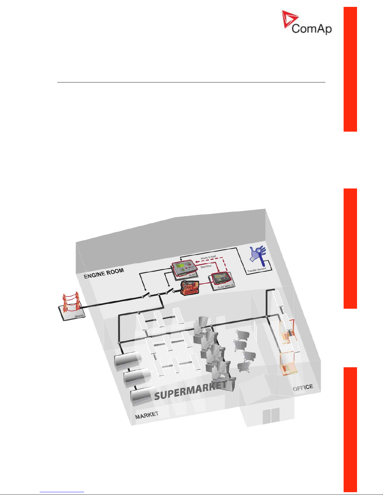
InteliATS
NT
is a comprehensive Automatic Transfer Switch controller designed to monitor the incoming
AC mains supply (1 or 3 phases) for under & over voltage, under & over frequency and voltage
unbalance. In the case of any mains supply disproportion it will send a remote start command to the
gen-set and make change over for both generator and mains contactors. The gen-set requires a
remote start type control unit (e.g. the ComAp InteliLite
NT
MRS 10 controller), at least a key-start box
with an external input for the start/stop signal.
InteliATS
NT
controllers are equipped with a powerful graphic display showing icons, symbols and bargraphs for intuitive operation, which sets, together with high functionality, new standards in Gen-set
controls.
The key features are:
• Easy-to-use operation and installation. Factory default configuration covers most of
applications
• Different customer changes are possible thanks to the configurability
• Excellent remote communication capabilities
• High reliability
Example application
Page 8

InteliATSNT PWR, SW version 1.0, ©ComAp – March 2009 8
IA-NT- PWR-1.0-Reference Guide R1.pdf
Configurability
One of the key features of the controller is high level of adaptability of the system to the needs of
every particular application. The way, how to achieve this, is the configuration.
NOTE:
Use LiteEdit PC software to read configuration from the controller or disk, view it, modify it and write
the configuration to controller or disk.
The firmware contains a number of binary inputs and outputs needed for all necessary functions
available in the firmware. But not all functions are required at the same time on different gen-sets and
also the controller hardware does not have so many input and output terminals. One of the main tasks
of the configuration is mapping of "logical" firmware inputs and outputs to the "physical" hardware
inputs and outputs.
Configuration parts:
1. Mapping of logical binary inputs (functions)
or assigning alarms to physical binary input
terminals
2. Mapping of logical binary outputs (functions)
to physical binary output terminals
3. Changing language of the controller texts
The controller is delivered with a default configuration, which should fit to most standart
applications. This default configuration can be changed only using PC and LiteEdit software. See
LiteEdit documentation for details.
NOTE:
You need one of communication modules to connect the controller to a PC with LiteEdit. There is a
special easy removable service module for cases, where there is no communication module
permanently attached.
Once the configuration is modified, it can be stored in a file for later usage with another controller or
for backup purposes. The file is called archive and has file extension ".ail". An archive contains full
image of the controller at the moment of saving (if the controller is online to the PC) except firmware,
i.e. besides configuration there are also current adjustment of all setpoints, all measured values, a
copy of history log and a copy of alarm list.
The archive can be simply used for cloning of controllers, which means preparing controllers with
identical configuration and settings.
What is in the package?
Accessories Description Optional / Obligatory
IA-NT PWR InteliATSNT central unit, PWR version Obligatory
IL-NT-RS232 RS232 communication card Optional
IL-NT-RS232-485 RS232 and RS485 communication card Optional
IL-NT-S-USB Service USB communication card Optional
*IL-NT RD Remote display software Optional
IB-Lite Internet communication bridge Optional
*Remote display for IA-NT controllers uses standard IL-NT controller with Remote display software
NOTE:
For detailed information about extension modules used with IA-NT controllers, please see the IL-NT,
IC-NT-Accessory Modules manual.
Page 9
InteliATSNT PWR, SW version 1.0, ©ComAp – March 2009 9
IA-NT- PWR-1.0-Reference Guide R1.pdf
IL-NT RS232 Communication module
IL-NT RS232 is optional plug-in card to enable InteliATS
NT
for RS232 communication. This is required
for computer or Modbus connecting. Card inserts into expansion slot back on the controller.
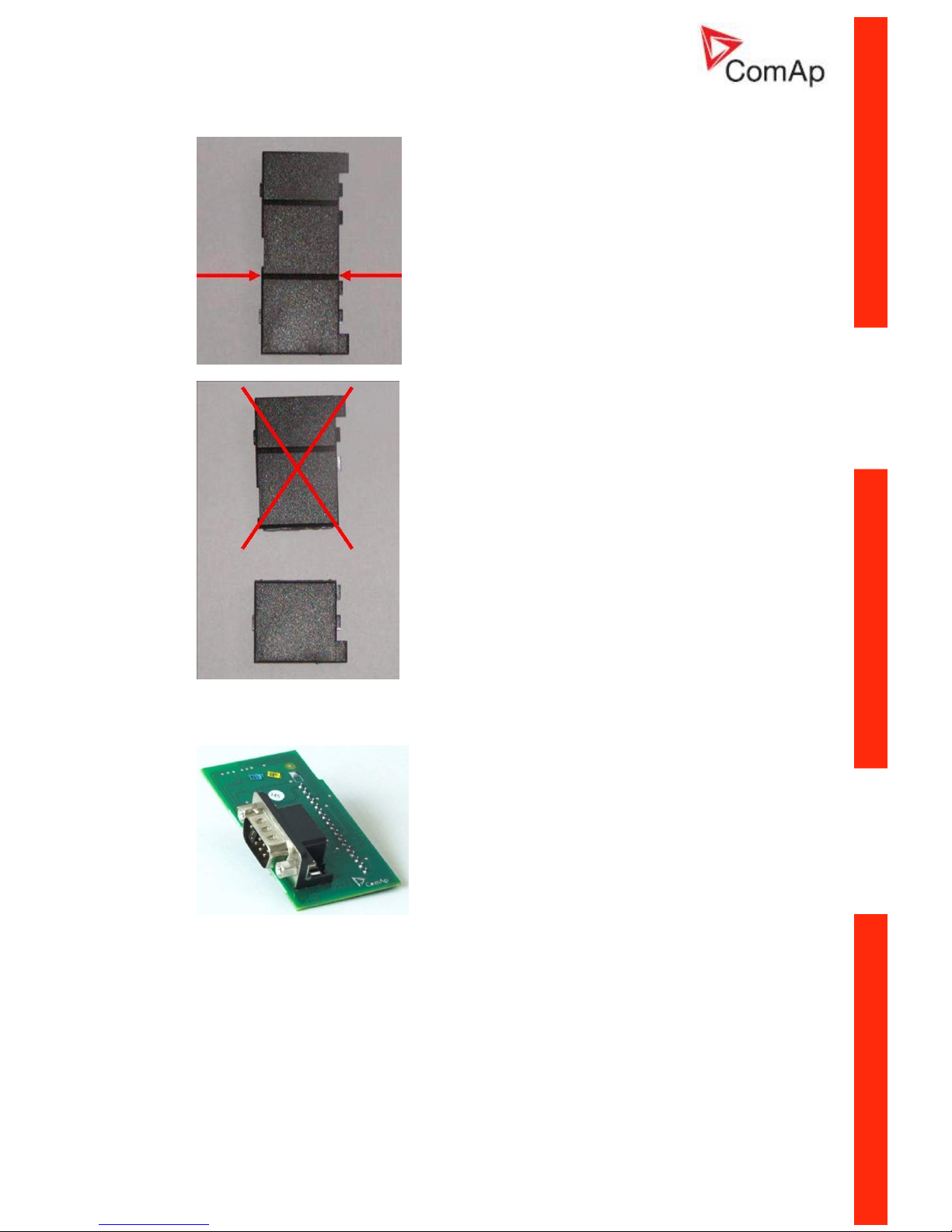
To insert the module, you must open the cover first (use screwdriver to open) and then insert the
module into slot. Once you have inserted it, the module will snap under plastic teeth. It is supposed to
be installed permanently. Should you need to remove it, the safest way is to remove whole back cover
and than remove module manually.
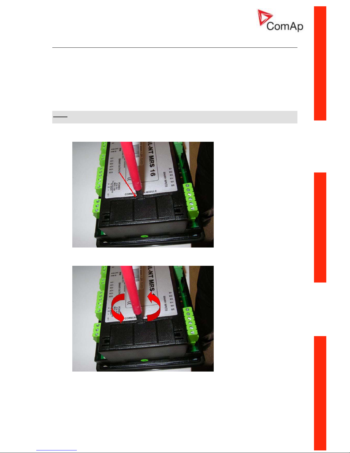
How to install RS 232 communication module:
NOTE:
The following procedure is analogic also for other communication modules.
1. Insert a screwdriver into the slot of the cover.
2. Move the screwdriver to set apart the small cover. Be careful!
3. Remove the small cover.
Page 10
InteliATSNT PWR, SW version 1.0, ©ComAp – March 2009 10
IA-NT- PWR-1.0-Reference Guide R1.pdf
4. Break apart the small cover into two pieces. Do not throw away the smaller part!
5. Take RS 232 communication module.
Page 11
InteliATSNT PWR, SW version 1.0, ©ComAp – March 2009 11
IA-NT- PWR-1.0-Reference Guide R1.pdf
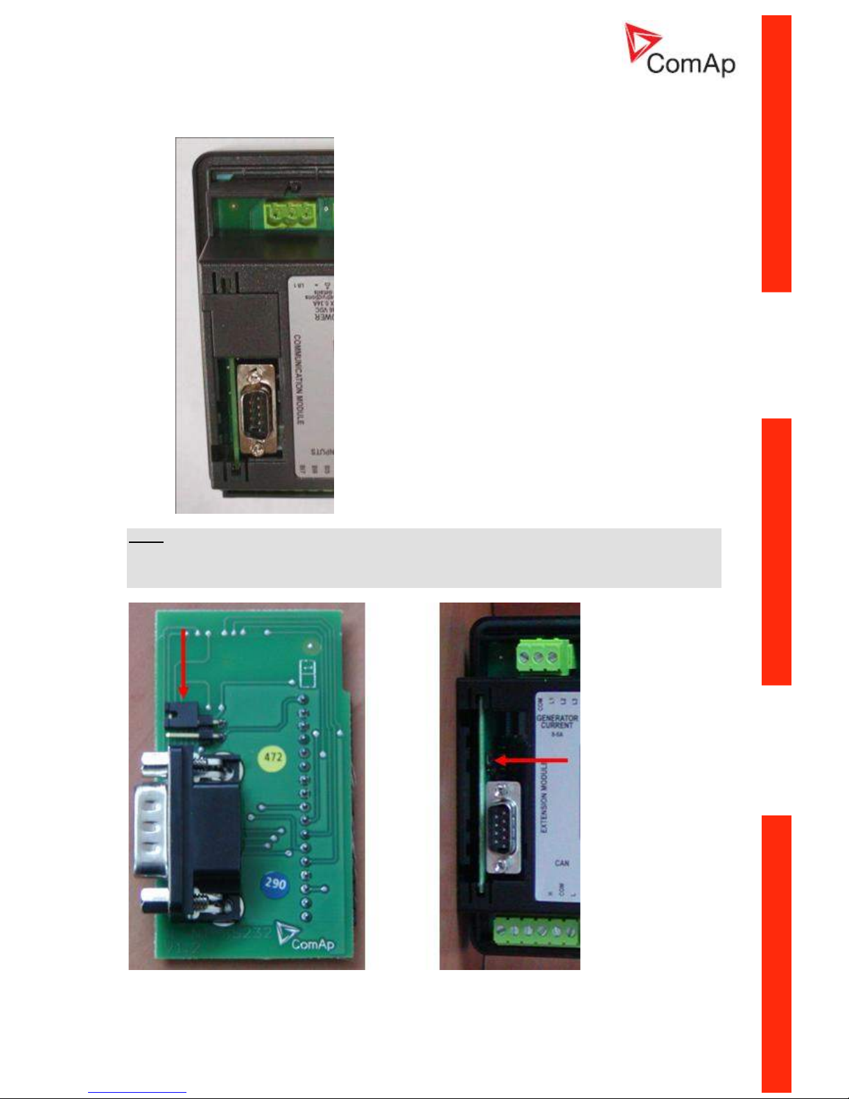
6. Plug RS 232 communication module into the slot of the controller.
7. Put back the small cover.
NOTE:
When you insert RS 232 communication module, the boot jumper is hidden. For that reason we
recommend to use RS 232 communication module with the boot jumper placed on it. See pictures
below:
RS 232 communication module with the boot jumper.
Page 12

InteliATSNT PWR, SW version 1.0, ©ComAp – March 2009 12
IA-NT- PWR-1.0-Reference Guide R1.pdf
IL-NT RS232-485 Communication module
IL-NT RS232-485 is optional plug-in card to enable InteliATS
NT
the RS232 and RS485 communication.
This is required for computer or Modbus connection. Card inserts into expansion slot back on the
controller. The IL-NT RS232-485 is a dual port module with RS232 and RS485 interfaces at
independent COM channels. The RS232 is connected to COM1 and RS485 to COM2.
To insert the module, please follow the instructions for IL-NT RS232 module, procedure is analogous.
You must open the cover first (use screwdriver to open) and then insert the module into slot. Once you
have insert it, the module will snap under plastic teeth. It is supposed to be installed permanently.
Should you need to remove it, the safest way is to remove whole back cover and than remove module
manually.
IL-NT S-USB Service USB communication module
IL-NT S-USB is optional plug-in card to enable InteliATS
NT
communication via USB port. This is
required for computer or Modbus connecting. Card inserts into expansion slot back on the controller.
To insert the module, please follow the instructions for IL-NT RS232 module, procedure is analogous.
You must open the cover first (use screwdriver to open) and then insert the module into slot. Once you
have inserted it, part of the module will remain over plastic box. It is supposed to be used as a service
tool. When you need to remove it, grab module in cutouts and pull it up manually.
NOTE:
Use the shielded USB A-B cable with this module! Recommended is ComAp cable – Order code:
“USB-LINK CABLE 1.8M”.
RS485
Boot jumper
RS485 Terminator jumper
RS232
Page 13

InteliATSNT PWR, SW version 1.0, ©ComAp – March 2009 13
IA-NT- PWR-1.0-Reference Guide R1.pdf
IL-NT RD Remote display software
IL-NT RD is remote display software for a controller. Remote display provides the same control and
monitoring functions as controller itself. Remote display for IA-NT controllers uses standard IA-NT
controller with IL-NT Remote display software. No further programing of the display is required – unit
is self configurable from the main controller. It is connected with the controller via IL-NT-RS232
communication modules using RS232 line. Longer distances (up to 1200m) are possible using IL-NTRS232-485 communication module or when RS232/RS485 converters are used.
The IL-NT RD hardware type should fit to the master IA-NT.
NOTE:
Please see the “IL-NT-RD Remote display software” chapter for more details.
IB-Lite Communication module
IB-Lite is optional plug-in card to enable InteliATS
NT
communication via Ethernet/Internet. Card inserts
into expansion slot back on the controller.
To insert the module, please follow the instructions for IL-NT RS232 module, procedure is analogous.
You must open the cover first (use screwdriver to open) and then insert the module into slot. Once you
have inserted it, part of the module will remain over plastic box. It is supposed to be used as a service
tool. When you need to remove it, grab module in cutouts and pull it up manually.
See IB-Lite-Reference Guide for further details.
Programming of IA-NT controller
Programming is possible only in OFF mode when the engine is not running.
NOTE:
For more information on programing, see LiteEdit Reference Guide.
CAUTION!
Check the statistic values after firmware upgrade. Readjust the values if necessary.
Page 14

InteliATSNT PWR, SW version 1.0, ©ComAp – March 2009 14
IA-NT- PWR-1.0-Reference Guide R1.pdf
User Interface
There is an interchangable User Interface on controller. It allows two different modes of displaying
controller menu.
The first mode called USER is dedicated for users who prefer easy function and need only monitor
actual values, see alarms or change language settings.
Second mode is called ENGINEER and it is dedicated for advaced users, who desire to change the
settings of controller, monitor all values and check the history of events.
Changing the mode of User Interface is possible from default measuring screen of controller by
simultaneous pressing the ENTER and PAGE button and than press again PAGE. On screen will be
displeyed the choice of two different User Interfaces.
Please see latest IA-NT Operator Guide for detailed description.
Page 15
InteliATSNT PWR, SW version 1.0, ©ComAp – March 2009 15
IA-NT- PWR-1.0-Reference Guide R1.pdf
Terminals
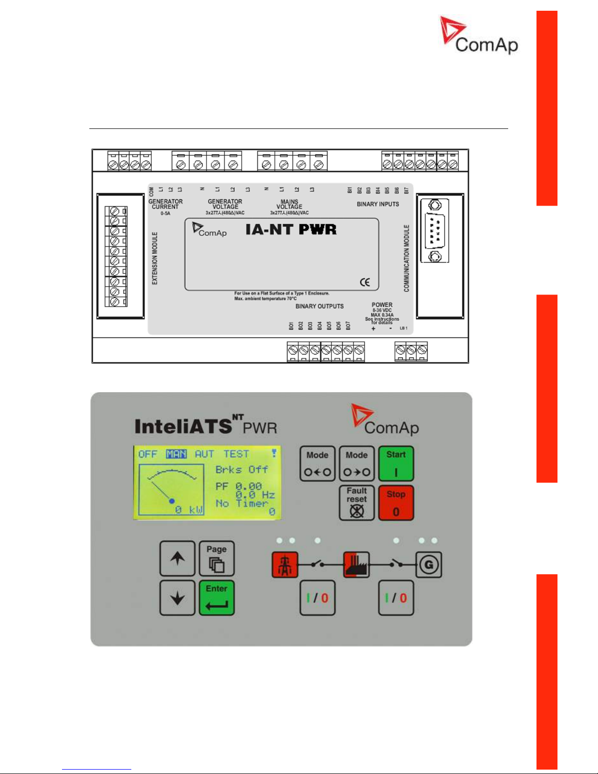
IA-NT PWR terminals and face
Page 16
InteliATSNT PWR, SW version 1.0, ©ComAp – March 2009 16
IA-NT- PWR-1.0-Reference Guide R1.pdf
Recommended Wiring
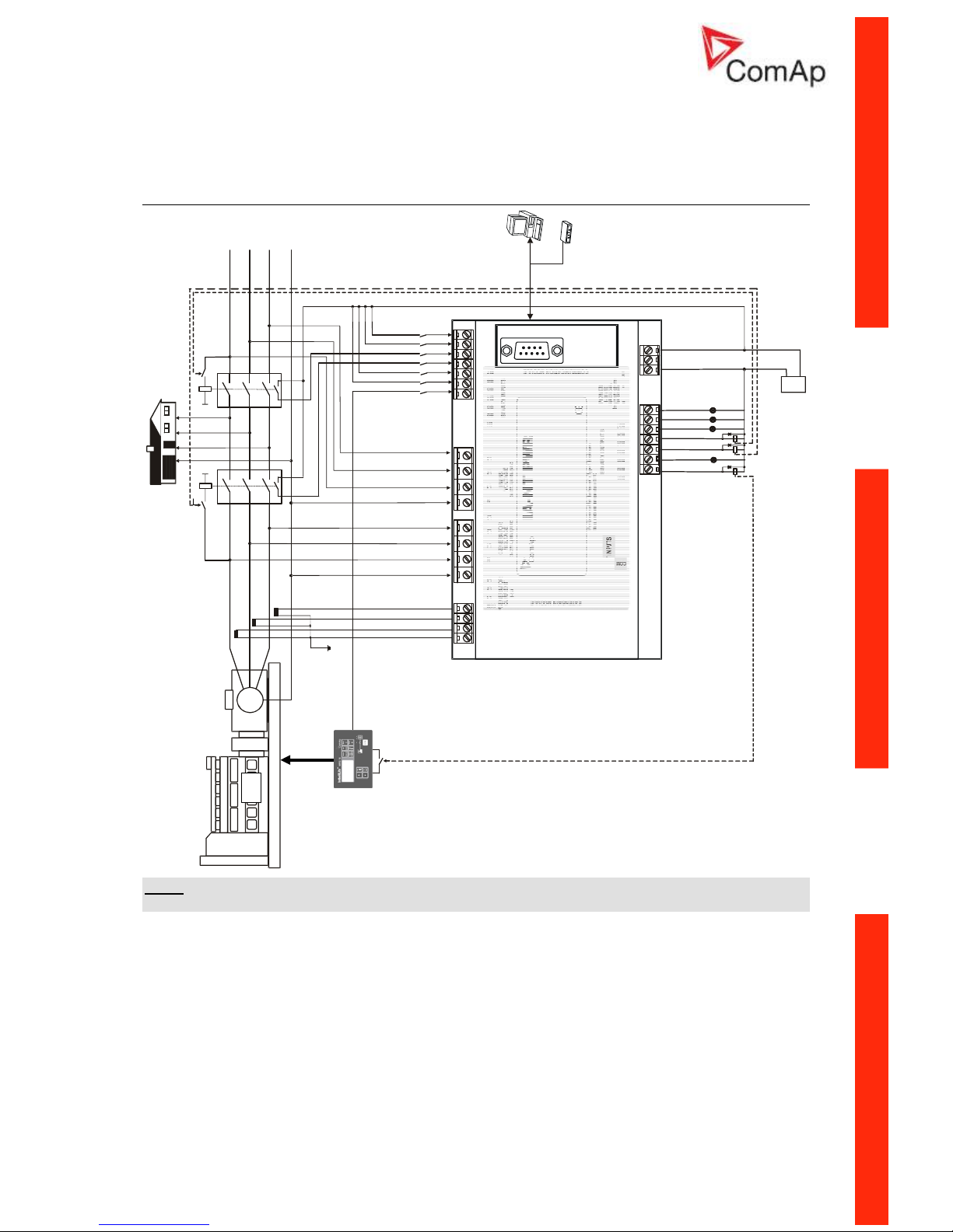
IA-NT PWR – Wiring Diagram
L1
L2
L3
N
DIESEL/GAS ENGINE
GENERATOR
G
RS-232C
Interface
Modemor PC
LOAD
B.Generator C.
.Mains C.B
GEN READY TO LOAD
MAINS FAIL BLOCK
REMOTE AUT
GCB FEEDBACK
MCB FEEDBACK
REMOTE TEST
REMOTE TEST ONLD
A
L
S
T
A
R
T
F
A
IL
G
C
B
C
L
O
S
E
/O
P
E
N
G
E
N
S
T
A
R
T
/S
T
O
P
A
L
M
A
IN
S
F
A
IL
A
L
A
R
M
R
E
A
D
Y
T
O
A
M
F
M
C
B
C
L
O
S
E
/O
P
E
N
CONTROL
SIGNALS
B
A
T
T
E
R
Y
-
+
+24V 0V
BINARY
OUTPUTS
GEN-SET CONTROLLER
NOTE:
MCB and GCB is recommended to be mechanically interlocked.
Page 17
InteliATSNT PWR, SW version 1.0, ©ComAp – March 2009 17
IA-NT- PWR-1.0-Reference Guide R1.pdf
Applications
The most typical application for the ATS controllers is Auto Mains Failure (AMF) application, where the
controller watches for the mains power supply fault and then starts a load transfer process.
Next possible application is manually controlled load transfer between two power supply sources
(mains x generator).
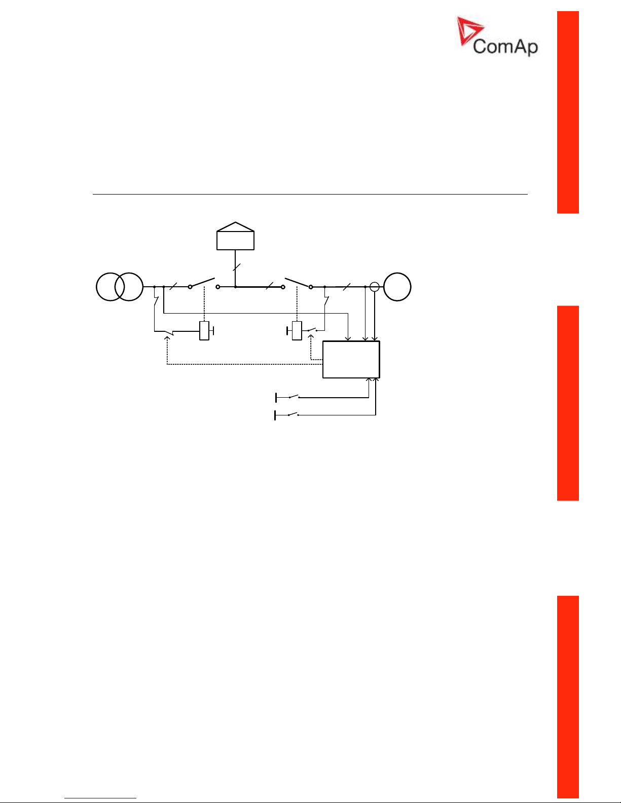
AMF using two separate breakers with feedbacks (MCB and GCB)
G
IA-NT
GCB
3x
LOAD
3xU
M
3xU
G
3xI
G
MCB
3x
T
3x
MCB
MCB FEEDBACK
K4
MCB GCB
GCB FEEDBACK
3x
MCB CLOSE/OPEN
GCB CLOSE/OPEN
BO
BI
MCB
K3
GCB
GCB
Specification
• Automatic remote gen-set start when the mains fails (AUT mode)
• GCB & MCB full control with feedbacks
• Break transfer on mains failure
• Break return on mains return (Load reclosing)
• Test mode (set running and waiting for mains failure)
Hardware requirements
1x IA-NT PWR
Setpoints
MCB Logic = “CLOSE-OFF”
Page 18
InteliATSNT PWR, SW version 1.0, ©ComAp – March 2009 18
IA-NT- PWR-1.0-Reference Guide R1.pdf
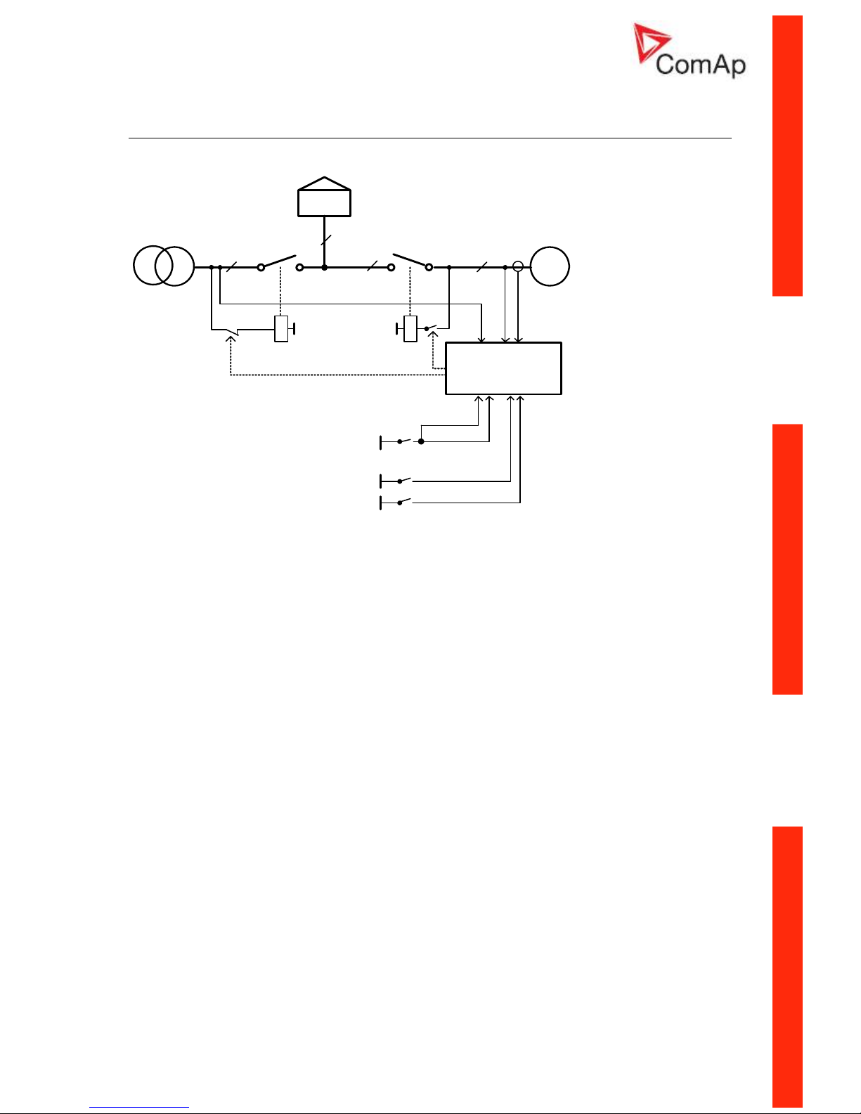
AMF using two separate breakers with feedbacks (MCB and GCB) +
Test on Load
G
GCB
3x
LOAD
3x UM3x UG3xI
G
MCB
3x
T
3x
K4
MCB GCB
K3
3x
BO
BI
IA-NT
MCB
MCB
FEEDBACK
GCB
GCB FEEDBACK
TEST ON LOAD
ON LOAD
TEST
REQUIRED
REMOTE
TEST
/CLOSE OPEN
GCB
MCB CLOSE /OPEN
Specification
• Automatic remote gen-set start when the mains fails (AUT mode)
• GCB & MCB full kontrol with feedbacks
• Break transfer on mains failure
• Break return on mains return (Load reclosing)
• Test mode (set running and waiting for mains failure)
• On Load Test - load transfer to gen-set (Island operation) and back to mains in TEST mode on
BI Test on load activation/deactivation. There are 2 breaks in this operation. Controller may
be forced to TEST mode by BI Remote TEST
Hardware requirements
1x IA-NT PWR
Setpoints
MCB Logic = “CLOSE-OFF”
RetFromIsland = “AUTO” – automatic return (MCB Close) to mains after TEST
RetFromIsland = “MANUAL” – mual return to mains (MCB Close) after TEST – IA-NT goes to MAN
mode.
Page 19
InteliATSNT PWR, SW version 1.0, ©ComAp – March 2009 19
IA-NT- PWR-1.0-Reference Guide R1.pdf
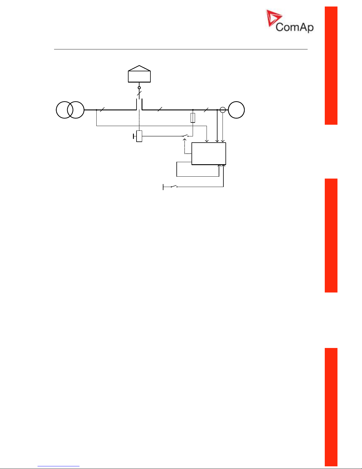
AMF using two-position ATS with feedback
G
IA-NT
3x
3xU
M
3xU
G
3x
I
G
3x
T
MCB FEEDBACK
GCB FEEDBACK
3x
MCB CLOSE/OPEN
GCB CLOSE/OPEN
BO
BI
K3
ATS on "II" position
LOAD
ATS
3x
ATS
I
II
Specification
• Automatic remote gen-set start when the mains fails (AUT mode)
• Two-position ATS control with feedback
• Break transfer on mains failure
• Break return on mains return (Load reclosing)
• Test mode (set running and waiting for mains failure)
Hardware requirements
1x IA-NT PWR
Setpoints
MCB Logic = “CLOSE-ON”
Page 20
InteliATSNT PWR, SW version 1.0, ©ComAp – March 2009 20
IA-NT- PWR-1.0-Reference Guide R1.pdf
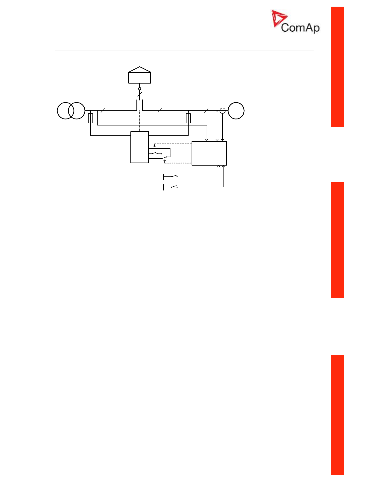
AMF using three-position ATS with feedbacks
G
IA-NT
3x
3xU
M
3xU
G
3x
I
G
3x
T
MCB FEEDBACK
GCB FEEDBACK
3x
MCB CLOSE/
OPEN
GCB CLOSE/
OPEN
BO
BI
ATS on "II" position
LOAD
ATS
3x
ATS
III0
ATS on "I" position
K4
K3
Specification
• Automatic remote gen-set start when the mains fails (AUT mode)
• Three-position ATS control with feedbacks, pass through neutral position
• Break transfer on mains failure
• Break return on mains return (Load reclosing)
• Test mode (set running and waiting for mains failure)
Hardware requirements
1x IA-NT PWR
Setpoints
MCB Logic = “CLOSE-ON”
Page 21

InteliATSNT PWR, SW version 1.0, ©ComAp – March 2009 21
IA-NT- PWR-1.0-Reference Guide R1.pdf
AMF + manual transfer & neutral control using three-position ATS
G
IA-NT
3x
3xU
M
3xU
G
3x
I
G
3x
T
REM TRANSFER
NEUTRAL POS
3x
MCB CLOSE/
OPEN
GCB CLOSE/
OPEN
BO
BI
Force Neutral Position
LOAD
ATS
3x
ATS
III0
Manual Load Transfer
K3
K4
K5
NEUTRAL
POS
Specification
• Automatic remote gen-set start when the mains fails (AUT mode)
• Three-position ATS control without feedback, pass through neutral position
• Manual request for load transfer (AUT mode)
• Request for switching to neutral position – the highest priority, overrides MCB & GCB state,
forces switch to neutral position. After deactivating return to previous state (MCB or GCB)
Hardware requirements
1x IA-NT PWR
Setpoints
MCB Logic = “CLOSE-ON”
Page 22

InteliATSNT PWR, SW version 1.0, ©ComAp – March 2009 22
IA-NT- PWR-1.0-Reference Guide R1.pdf
AMF + no battery operation
3xU
M
3xU
G
Specification
It is possible to operate controller without a battery supplying the controller. For such operation the
following conditions have to be fulfilled:
• Controller is supplied from 24V/2.5A AC/DC power supply whose source is switched between
Mains and Gen-set via relay (another contacts of the relay for GCB switching) according to
the Mains state (OK/Fault). See the schematic diagram for more details
• Normally closed relay contacts have to be used for the gen-set start command. Setpoint
“GenStart Logic” has to be set to CLOSE-OFF
• Switching of the 24V AC/DC power supply is blocked when GCB is closed, so the power
supply is not switched to Mains if voltage on the mains bus appears – protection against
“Flip-flopping” of the power supply when voltage changes arise on Mains.
It (power supply) will be switched to Mains when GCB is opened.
Then in the case of Mains failure:
• 24V AC/DC power supply source is switched to gen-set
• Voltage supplying controller disappears
• Gen Start relay is deenergized and contacts closed
• Gen-set is started
• Controller is supplied from running gen-set
• Controller is initialized, waits for Gen OK conditions
• MCB is opened, GCB closed and the 24V AC/DC power supply source is locked in gen-set
position.
If Mains returns:
• GCB is opened, 24V AC/DC power supply source is unlocked and switched to Mains
• MCB is closed
• Gen-set is stopped
Hardware requirements
1x IA-NT PWR
1x 24V/2.5A AC/DC power supply
Page 23

InteliATSNT PWR, SW version 1.0, ©ComAp – March 2009 23
IA-NT- PWR-1.0-Reference Guide R1.pdf
Getting Started
How to install
General
To ensure proper function:
• Wiring for binary inputs and analog inputs must not be run with power cables.
• Binary inputs should use shielded cables, especially when length >3m.
Power supply
To ensure proper function:
• Use min. power supply cable of 1.5mm
2
Maximum continuous DC power supply voltage is 36VDC. Maximum allowable power supply voltage
is 39VDC. The InteliATS
NT
’s power supply terminals are protected against large pulse power
disturbances. When there is a potential risk of the controller being subjected to conditions outside its
capabilities, an outside protection devise should be used.
NOTE:
The InteliATSNT controller should be grounded properly in order to protect against lighting strikes!!
The maximum allowable current through the controller’s negative terminal is 4A (this is dependent on
binary output load).
For the connections with 12VDC power supply, the InteliATS
NT
includes internal capacitors that allow
the controller to continue operation if the battery voltage dip occurs. If the voltage before dip is 10V,
after 100ms the voltage recovers to 7 V, the controller continues operating. During this voltage dip the
controller screen backlight can turn off and on but the controller keeps operating.
It is possible to further support the controller by connecting the external capacitor and separating
diode or I-LBA module:
The capacitor size depends on required time. It shall be approximately thousands of microFarads.
The capacitor size should be 5 000 microFarad to withstand 150ms voltage dip under following
conditions:
Voltage before dip is 12V, after 150ms the voltage recovers to min. allowed voltage, i.e. 8V
NOTE:
Before the battery is discharged the message "Low BackupBatt" appears.
Page 24

InteliATSNT PWR, SW version 1.0, ©ComAp – March 2009 24
IA-NT- PWR-1.0-Reference Guide R1.pdf
Or by connecting special I-LBA Low Battery Adaptor module:
The I-LBA module ensures min. 350ms voltage dip under following conditions:
RS232 and other plug-in module is connected.
Voltage before dip is 12V and after 350ms the voltage recovers to min. allowed voltage 5V.
The I-LBA enables controller operation from 5VDC (for 10 to 30 sec).
The wiring resistance from battery should be up to 0.1 Ohm for I-LBA proper function.
NOTE:
I-LBA may not eliminate voltage drop when used with low temperature (-40°C) version of controller
and display heating element is on (below 5°C). Current drain of heating element exhausts LBA
capacitors very fast
Power supply fusing
A one-amp fuse should be connected in-line with the battery positive terminal to the controller and
modules.
Fuse value and type depends on number of connected devices and wire length.
Recommended fuse (not fast) type - T1A. Not fast due to internal capacitors charging during
power up.
Binary output protections
NOTE:
Do not connect binary outputs directly to DC relays without protection diodes, even if they are not
connected directly to controller outputs.
Page 25

InteliATSNT PWR, SW version 1.0, ©ComAp – March 2009 25
IA-NT- PWR-1.0-Reference Guide R1.pdf
Grounding
To ensure proper function:
• Use as short as possible cable to the grounding point on the switchboard
• Use cable min. 2,5mm
2
• The “-“ terminal of the battery has to be properly grounded
Three phase applications
Current measurement
To ensure proper function
Use cables of 2,5mm
2
Use transformers to 5A
Connect CT according to following drawings
Voltage measurement
G
GENERATOR MAINS
L3L2L1N
L1
L2
L3
N
L3L2L1N
G
GENERATOR MAINS
L3L2L1N
L1
L2
L3
L3L2L1N
NOTE:
No separation transformers for three wires voltage connection (without N) are needed.
Switchboard lighting strikes protection according standard regulation is expected!!!
Page 26

InteliATSNT PWR, SW version 1.0, ©ComAp – March 2009 26
IA-NT- PWR-1.0-Reference Guide R1.pdf
Single phase applications
There is not a separate archive file for single-phase applications. Use standard ail archives.
Recommended wirings
Generator (and mains) single-phase voltage has to be connected to all three-voltage terminals L1, L2
and L3. Generator current has to be connected to L1l and COM terminals only.
Voltage measurement
G
GENERATOR MAINS
L3L2L1N
L
N
L3L2L1N
NOTE:
Switchboard lighting strikes protection according standard regulation is expected!!!
Current measurement
To ensure proper function
Use cables of 2,5mm
2
Use transformers to 5A
Connect CT according to following drawings. Terminals L2l and L3l are opened.
Set points adjustment
To run a single-phase application, the following set points have to be set:
Gener Protect: Amps Unbal Sd to 200 %
Gener Protect: Amps Unbal Del to 60,0 s
Page 27

InteliATSNT PWR, SW version 1.0, ©ComAp – March 2009 27
IA-NT- PWR-1.0-Reference Guide R1.pdf
Binary inputs
Binary outputs
+
Battery
-
iL
4k7
Ω
+
-
Power
Supply
+
Battery
-
iL
LOAD
+
-
Power
Supply
Page 28

InteliATSNT PWR, SW version 1.0, ©ComAp – March 2009 28
IA-NT- PWR-1.0-Reference Guide R1.pdf
Inputs and Outputs
For Inputs/Outputs overview table see chapter Technical Data.
NOTE:
Any Binary input or output can be configured to any IA-NT controller terminal or changed to different
function by LiteEdit software. There is fix 1 sec delay when any binary input is configured as
protection.
Not Used
Binary input has no function. Use this configuration when Binary input is not connected.
Alarm
If the input is closed (or opened) selected alarm is activated.
Binary Alarm configuration items
Name 14 characters ASCII string
NC Normally closed Contact type
NO Normally opened
Warning Alarm type
Trip
All the time Valid if checkbox “Engine running
only” is not checked
Alarm active
Engine running only Valid if checkbox “Engine running
only” is checked
Control
Use this setting to configure the desired function from the list below.
Page 29

InteliATSNT PWR, SW version 1.0, ©ComAp – March 2009 29
IA-NT- PWR-1.0-Reference Guide R1.pdf
Binary inputs IA-NT - default
BI1 GenReadyToLoad
BI2 MainsFailBlock
BI3 Remote AUT
BI4 GCB Feedback
BI5 MCB Feedback
BI6 Remote TEST
BI7 Remote TEST OnLd
Binary inputs – list
Rem Start/Stop
External request for engine run. AUT mode only.
NOTE:
If the binary input Rem Start/Stop is active and mains failure occures, the MCB breaker opens and
after the Trans Del delay the GCB breaker is closed. Once the mains is OK, the MainsReturnDel delay
elaspes and the GCB breaker is opened. Then after the Trans Del delay is MCB breaker closed. Genset remains running as long as Rem Start/Stop is active. See AMF time chart for more details.
Rem Transfer
External request for an immediate transfer from mains to generator without waiting for the AMF
Settings: EmergStart Del has elapsed. In the case the transfer not succeeded the system will stay in
neutral position. The MainsFailBlock input performs its work normally.
GCB Feedback
Use this input for indication, whether the generator circuit breaker is open or closed.
If the feedback is not used, connect this input to the output GCB CLOSE/OPEN
MCB Feedback
This input indicates whether MCB is closed or opened.
Emergency Stop
If the input is opened, the stop signal for the gen-set is sent and the MCB and GCB are opened. Input
is inverted (normally closed) in default configuration.
Access Lock
If the input is closed, no setpoints can be adjusted from controller front panel and gen-set mode (OFFMAN-AUT-TEST) cannot be changed.
NOTE:
Access Lock does not protect setpoints and mode changing from LiteEdit. To avoid unqualified
changes the selected setpoints can be password protected. Also the button Fault reset, is not blocked
at all and buttons Start and Stop in MAN mode are not blocked.
Page 30

InteliATSNT PWR, SW version 1.0, ©ComAp – March 2009 30
IA-NT- PWR-1.0-Reference Guide R1.pdf
Remote OFF
If closed, IA-NT is switched to OFF mode (there are four modes OFF-MAN-AUT-TEST). When opens
controller is switched back to previous mode.
NOTE:
This binary input should be connected to schedule timer switch, to avoid start of engine.
Remote MAN
If the input is active, MAN mode is forced to the controller independently on the position of the MODE
selector.
Remote AUT
If the input is active, AUTO mode is forced to the controller independently on the position of the MODE
selector. If another of remote inputs is active, then the REMOTE AUT input has the lowest priority.
Remote TEST
If closed, IA-NT is switched to TEST mode (there are four modes OFF-MAN-AUT-TEST). When opens
controller is switched back to previous mode.
Rem TEST OnLd
Affects the behavior in TEST mode. When input is closed, the controller automatically transfers load
from the mains to the gen-set. Setpoint AMF Settings: ReturnFromTEST must be set to MANUAL.
Load is automatically transferred back to the mains when any gen-set shut down protection activates.
RemControlLock
If the input is active, setpoints writing or command sending from the external terminal is disabled.
FaultResButton
Binary input has the same function as Fault Reset button on the InteliATSNT front panel.
GCB Button
Binary input has the same function as GCB button on the InteliATSNT front panel. It is active in MAN
mode only.
MCB Button
Binary input has the same function as MCB button on the InteliATSNT front panel. It is active in MAN
mode only.
MainsFailBlock
If the input is closed, the automatic start of the gen-set at Mains failure is blocked. In case of running
gen-set the GCB is opened, gen-set goes to Cooling procedure and stops.
GenReadyToLoad
Indicates wether the gen-set is ready to undertake load. Conditions for successful gen-set start and
readiness to undertake load can be – depending on the GenerProtect setpoint – evaluated from the
voltage and the frequency of the generator or from the state of GenReadyToLoad input. The
conditions have to be fulfilled during time defined by the MaxGenStartDel setpoint (which can be even
unlimited). More info can be found in the setpoint description.
Neutral Pos
In MAN mode this input switches a three position ATS switch to its neutral position – it activates the
binary output NeutralPosition and switches the MCB and GCB off.
Page 31

InteliATSNT PWR, SW version 1.0, ©ComAp – March 2009 31
IA-NT- PWR-1.0-Reference Guide R1.pdf
Binary outputs IA-NT - default
BO1 GenStart/Stop
BO2 Alarm
BO3 GCB Close/Open
BO4 MCB Close/Open
BO5 Ready To AMF
BO6 AL Mains Fail
BO7 AL Start Fail
Binary outputs - list
Not Used
Output has no function.
GenStart/Stop
The closed relay sends remote start signal to the gen-set. Generator protections are blocked when the
output is inactive and the GCB is blocked too. Output can be inverted (CLOSE-OFF) using Basic
Settings: GenStart Logic setpoint.
Prestart
The output closes when the gen-set start is requested and opens after the AMF Settings: Prestart
Time has elapsed. Afterwards the GenStart/Stop output is activated as a start signal for the remote
gen-set.
Pretransfer
Is activated during the Prestart phase when the Mains Fail had occurred and the gen-set start is the
result of this event. See the AMF Settings: Prestart Time setpoint for more info.
Alarm
The output closes if :
• any alarm comes up or
The output opens if
• FAULT RESET is pressed
The output closes again if a new fault comes up.
GCB Close/Open
The output controls the generator circuit breaker.
NOTE:
Supposed time to close (reaction time) of GCB is 0.1 sec.
GCB ON Coil
The output activates Generator Circuit Breaker coil.
GCB OFF Coil
The output deactivates Generator Circuit Breaker coil.
Page 32

InteliATSNT PWR, SW version 1.0, ©ComAp – March 2009 32
IA-NT- PWR-1.0-Reference Guide R1.pdf
GCB UV Coil
The output controls Generator Circuit Breaker coil after voltage drop-out.
MCB Close/Open
The output controls the mains circuit breaker.
MCB ON Coil
The output activates Mains Circuit Breaker coil.
MCB OFF Coil
The output deactivates Mains Circuit Breaker coil.
MCB UV Coil
The output controls Mains Circuit Breaker coil after voltage drop-out.
Gen Healthy
The output is a copy of generator status LED on IA-NT front panel. The output is closed if gen-set is
running and all gen-set electric values are in limits.
Ready To AMF
The output is active, if the controller is able to start the engine and simultaneously the controller is in
AUT Mode.
Ready
The output is closed if following conditions are fulfilled:
• Gen-set is not running and
• Controller is not in OFF Mode
Ready To Load
The output is closed if gen-set is running and all electric values are in limits and no alarm is active - it
is possible to close GCB or it is already closed. The output opens during cooling state.
Cooling
The output closes when system is in Cooling state.
Mains Healthy
The output is copy of mains status LED on IA-NT front panel. The output is closed if mains voltage
and frequency are within limits.
AL Gen >V
The output closes if the generator overvoltage shutdown alarm activates.
The output opens, if
• alarm is not active and
• FAULT RESET is pressed
AL Gen <V
The output closes if the generator undervoltage shutdown alarm activates.
The output opens, if
• alarm is not active and
• FAULT RESET is pressed
AL Gen Volts
The output closes if the generator over/under voltage alarm or voltage asymmetry alarm activates.
The output opens, if
Page 33

InteliATSNT PWR, SW version 1.0, ©ComAp – March 2009 33
IA-NT- PWR-1.0-Reference Guide R1.pdf
• alarm is not active and
• FAULT RESET is pressed
AL Gen Freq
Output closes if the generator over/under frequency alarm activates.
The output opens, if
• alarm is not active and
• FAULT RESET is pressed
AL Gen >Freq
Output closes if the generator over frequency alarm activates.
The output opens, if
• alarm is not active and
• FAULT RESET is pressed
AL Gen <Freq
Output closes if the generator under frequency alarm activates.
The output opens, if
• alarm is not active and
• FAULT RESET is pressed
AL Mains Volts
The output closes if the mains over/under voltage alarm or voltage asymmetry alarm activates.
The output opens, if
• alarm is not active
AL Mains Freq
Output closes if the mains over/under frequency alarm activates.
The output opens, if
• alarm is not active
AL Stop Fail
Output closes when the engine have to be stopped, but speed or frequency or voltage or oil pressure
is detected. This protection goes active 60s after stop command. With start goes this protection
inactive.
The output opens, if
• alarm is not active and
• FAULT RESET is pressed
AL Mains Fail
Output closes if the mains over/under voltage alarm, voltage asymmetry alarm or mains over/under
frequency alarm activates.
The output opens, if
• alarm is not active
AL Start Fail
Output closes after the gen-set start-up fails.
The output opens, if
• alarm is not active and
• FAULT RESET is pressed
AL Overcurrent
Output closes if the generator
• IDMT over current or
• current unbalance or
Page 34

InteliATSNT PWR, SW version 1.0, ©ComAp – March 2009 34
IA-NT- PWR-1.0-Reference Guide R1.pdf
• short current alarm activates.
The output opens, if
• Alarm is not active and
• FAULT RESET is pressed
AL BatteryFail
Output closes when IA-NT performs reset during start procedure (probably due to weak battery) or
when battery under/over voltage warning appears.
The output opens, if
• alarm is not active and
• FAULT RESET is pressed
AL Common Wrn
Output closes when any warning alarm appears.
The output opens, if
• No warning alarm is active and
• FAULT RESET is pressed
AL Common Trip
Output closes when any trip alarm appears.
The output opens, if
• No trip alarm is active and
• FAULT RESET is pressed
Mode OFF
The output is closed, if OFF Mode is selected.
Mode MAN
The output is closed, if MAN Mode is selected.
Mode AUT
The output is closed, if AUT Mode is selected.
Mode TEST
The output is closed, if TEST mode is selected.
The output opens, if
• Alarm is not active and
• FAULT RESET is pressed
Exerc Timer 1
Output activates when Timer 1 is active. Simultaneously, gen-set is started when it is in AUT mode.
Exerc Timer 2
Output activates when Timer 2 is active. Simultaneously, gen-set is started when it is in AUT mode.
Not In AUT
Output activates when the controller is not in AUT mode.
Neutral Pos
Switches ATS switch to its neutral position.
Neutral Coil
Activates the neutral position coil of the ATS switch.
Page 35

InteliATSNT PWR, SW version 1.0, ©ComAp – March 2009 35
IA-NT- PWR-1.0-Reference Guide R1.pdf
Setpoints
Password
EnterPassword
Password is a four-digit number. Password enables change of relevant protected setpoints.
Use ↑ or ↓ keys to set and ENTER key to enter the password.
NOTE:
There is only 1 level of a password.
ChangePassword
Use ↑ or ↓ keys to set and ENTER key to change the password.
NOTE:
At first the password has to be entered before the new password can be changed.
Basic Settings
ControllerName
User defined name, used for InteliNT identification at remote phone or mobile connection.
ControllerName is max 14 characters long and have to be entered using LiteEdit software.
Nominal Power [kW]
Nominal power of the generator
Step: 1kW
Range: 1 – 5000 kW
Nomin Current [ A ]
It is current limit for generator IDMT over current and short current protection and means maximal
continuous generator current. See Gener Protect: Amps IDMT Del, Short Crct Sd setpoints.
Nominal Current can be different from generator rated current value.
Step: 1 A
Range: 1 - 10000 A
CT Ratio [/5A]
Gen-set phases current transformers ratio.
Step: 1 A
Range: 1 – 5000 A / 5A
NOTE:
For CT Ratio <= 250 the values of power and current are displayed in a controller with one decimal.
For CT Ratio > 250 the values of power and current are displayed in a controller with integral
numbers. If you change CT Ratio in LiteEdit or directly in the controller, decimal numbers will not be
changed immediately. The change will be executed only by reconfiguring in LiteEdit. The statistics of
power will be recounted at this time with regards to decimal numbers of power.
WARNING! When you change the firmware, statistics can be invalid!
PT Ratio [/1]
Gen-set potential transformers ratio.
Step: 0,1 V / V
Range: 0,1 – 500,0 V / V
Page 36

InteliATSNT PWR, SW version 1.0, ©ComAp – March 2009 36
IA-NT- PWR-1.0-Reference Guide R1.pdf
Vm PT Ratio [/1]
Mains potential transformers ratio.
Step: 0,1 V / V
Range: 0,1 – 500,0 V / V
Nomin Volts [V]
Nominal generator voltage (phase to neutral)
Step: 1V
Range: 80 – 20000 V
Nominal Freq [Hz]
Nominal generator frequency (usually 50 or 60 Hz )
Step: 1Hz
Range: 45 – 65 Hz
ActivityAtOFF [ENABLE/DISABLE]
ENABLE: Controller at OFF mode stays at standard behavior of OFF mode.
DISABLE: Controller at OFF mode opens all binary outputs and there is Fault reset active all the
time.
ControllerMode [OFF, MAN, AUT,TEST]
Equivalent to Controller mode changes by MODE→ or ←MODE buttons.
NOTE:
Controller Mode change can be separately password protected.
ControllerAddr (1 .. 32) [-]
Controller identification number. It is possible to set controller address different from the default value
(1) so that more controllers can be interconnected (via RS485) and accessed e.g. from Modbus
terminal.
NOTE:
When opening connection to the controller it's address has to correspond with the setting in PC tool.
From LiteEdit it is only possible to connect to controllers with address 1.
COM1 Mode [DIRECT/MODEM/MODBUS]
Communication protocol switch for the COM1 channel.
DIRECT: LiteEdit communication protocol via direct cable.
MODEM: LiteEdit communication protocol via modem.
MODBUS: Modbus protocol. See detailed description in InteliCommunication guide.
NOTE:
For details on communic. speed and other technical parameters please see chapter Technical Data.
For detail description see chapter Modbus protocol. Register oriented modbus is supported.
COM2 Mode [DIRECT/MODBUS]
Communication protocol switch for the COM2 channel, if dual communication module is pluged in.
DIRECT: LiteEdit communication protocol via direct cable.
MODBUS: Modbus protocol. See detailed description in InteliCommunication guide.
NOTE:
For details on communic. speed and other technical parameters please see chapter Technical Data.
For detail description see chapter Modbus protocol. Register oriented modbus is supported.
Page 37

InteliATSNT PWR, SW version 1.0, ©ComAp – March 2009 37
IA-NT- PWR-1.0-Reference Guide R1.pdf
GenStart Logic [CLOSE-ON/CLOSE-OFF]
The set point influences the behavior of the output Gen Start/Stop.
CLOSE-ON: Gen-set should start when the output Gen Start/Stop is closed.
CLOSE-OFF: Gen-set should start when the output Gen Start/Stop is opened.
Batt Undervolt [V]
Warning threshold for low battery voltage.
Step: 0,1 V
Range: 8V – 40 (Battery >Volts)
Batt Overvolt [V]
Warning threshold for hi battery voltage.
Step: 0,1 V
Range: 8V – 40 (Battery <Volts)
Batt Volt Del [s]
Delay for low battery voltage alarm.
Step: 1s
Range: 0 – 600 s
Engine Params
Prestart Time [s]
Time of closing of the Prestart and/or Pretransfer output prior to the engine start.
Set to zero if you want to leave the output Prestart/Pretransfer open.
Step: 1s
Range: 0 – 600 s
Cooling Time [s]
Runtime of the unloaded gen-set to cool the engine before stop.
Step: 1s
Range: 0 – 3600 s
Max Start Del [s]
This timeout starts after closing binary output GEN START/STOP. When generator does not reach
defined limits Basic Settings: Nominal Freq) within Max Start Del, Trp Start Fail alarm occurs and the
gen-set will shut down. See the table below for a description of the engine start evaluation.
If MaxStartDel is longer then 600 s it means there is NO TIMEOUT.
Step: 1s
Range: 0 – 600 s, 601 s = NO TIMEOUT
Page 38

InteliATSNT PWR, SW version 1.0, ©ComAp – March 2009 38
IA-NT- PWR-1.0-Reference Guide R1.pdf
Engine start evaluation diagram:
Min Stab Time [s]
Minimum time interval between defined generator voltage is reached to GCB is closed.
If BI: GenReadyToLoad is not configured, timer is not used.
Step: 1s
Range: 1 – 300 s
Stop Time [s]
Period given by the value of the Stop Time setpoint tells the controller how long should it wait for the
engine to change to the stop state (stop state means GenReadyToLoad signal is deactivated or
generator voltages disappeared). If the engine is still running after the stop time expires the Wrn Stop
Fail alarm is announced. Stop Fail starts counting always when the controller sends Stop command to
the engine (Start/Stop output is deactivated).
Step: 1s
Range: 0 – 3601 sec Value 3601 means the controller doesn’t care for the engine is
stopped (Wrn Stop Fail is never announced).
Page 39

InteliATSNT PWR, SW version 1.0, ©ComAp – March 2009 39
IA-NT- PWR-1.0-Reference Guide R1.pdf
Gener Protect
NOTE:
All electric protections when activated result in shutdown.
GenerProtect [ENABLE/DISABLE]
ENABLE: Generator protections of the controller are active.
DISABLE: Generator protections of the controller are inactive.
Short Crct Trp [%]
Shutdown occurs when generator current reaches Short Crct Sd limit.
Step: 1 % of Nominal current
Range: 100 - 500 %
Short Crct Del [s]
Delay for generator shorcurrent alarm.
Step: 0.01s
Range: 0.00 – 10.00 s
Amps IDMT Del [s]
IDMT curve shape selection. Amps IDMT Del is Reaction time of IDMT protection for 200%
overcurrent Igen = 2* Nomin Current.
Step: 0.1 s
Range: 0.1 - 60.0 s
IDMT is “very inverse” generator over current protection. Reaction time is not constant but depends on
generator over current level according following formula.
Amps IDMT Del * Nomin Current
Reaction time =
Igen - Nomin Current
Igen is maximal value of all measured phases of generator current.
NOTE:
Reaction time is limited up to 900 sec = 15 minutes. IDMT protection is not active for Reaction time
values longer than 15 minutes.
EXAMPLE of Reaction time for different over current levels. Values in column 200% are IDMT Curr
Del.
Overcurrent
200 % =
IDMT Curr
Del
≤ 100 % 101 % 110 %
0,2 s
No action 20 s 2 s
2 s
No action 200 s 20 s
Reaction time
20 s
No action No action
(time > 900 s)
200 s
Page 40

InteliATSNT PWR, SW version 1.0, ©ComAp – March 2009 40
IA-NT- PWR-1.0-Reference Guide R1.pdf
Igen
Nominal Current
Short Crct Sd
Amps IDMT Del
Maximal Reaction time
Rea c tio n time
Amps Unbal Trp [%]
Threshold for generator current asymmetry (unbalance).
Step: 1% of Nominal current
Range: 1 – 200% of Nominal current
Amps Unbal Del [s]
Delay for generator current unbalance
Step: 0.1 s
Range: 0.0 – 600.0 s
Gen >V Trp [%]
Threshold for generator overvoltage. All three phases are checked. Maximum out of three is used.
Step: 1% of Nominal voltage
Range: 0(Gen <V Sd) – 200%
Gen <V Trp [%]
Threshold for generator undervoltage. All three phases are checked. Minimum out of three is used.
Step: 1% of Nominal voltage
Range: 0% – 200 (Gen >V Sd)%
Gen V Del [s]
Delay for generator undervoltage and overvoltage alarm
Step: 0.1s
Range: 0.0 – 600.0 s
Volt Unbal Trp [%]
Threshold for generator voltage unbalance alarm.
Step: 1% of Nominal voltage
Range: 0 – 200% of Nominal voltage
Page 41

InteliATSNT PWR, SW version 1.0, ©ComAp – March 2009 41
IA-NT- PWR-1.0-Reference Guide R1.pdf
Volt Unbal Del [s]
Delay for generator voltage unbalance alarm.
Step: 0.1s
Range: 0.0 – 600.0 s
Gen >Freq Trp [% ]
Threshold for generator phase L3 overfrequency.
Step: 0.1% of Nominal frequency
Range: 0 (Gen <Freq Sd) – 200.0% of Nominal frequency
Gen <Freq Trp [% ]
Threshold for generator phase L3 underfrequency.
Step: 0.1% of Nominal frequency
Range: 0.0 – 200 (Gen >Freq Sd ) % of Nominal frequency
Gen Freq Del [s]
Delay for generator underfrequency and overfrequency alarm.
Step: 0.1s
Range: 0.0 – 600.0 s
AMF Settings
RetFromIsland [MANUAL, AUTO]
MANUAL: After closing GCB, IA-NT goes to MAN Mode automatically.
AUTO: No automatic switching to MAN Mode.
EmergStart Del [s]
Delay after the mains failure to the start of the gen-set
Step: 1s
Range: 0 – 6000 s
MainsReturnDel [s]
Delay after the mains return to the GCB opening.
Step: 1s
Range: 1 – 3600 s
Transfer Del [s]
Delay after GCB opening to MCB closing during the return procedure.
Delay after MCB opening to GCB closing if the setpoint MCB Opens On set to GENRUN
Step: 0.1s
Range: 0 – 600.0 s
Page 42

InteliATSNT PWR, SW version 1.0, ©ComAp – March 2009 42
IA-NT- PWR-1.0-Reference Guide R1.pdf
The time charts bellow show recommended setting of AMF Settings: Transfer Del setpoint.
If the Transfer Del setpoint is set shorter If some delay between MCB feedback
than the time required for opening of the deactivation and closing of GCB Close/Open
circuit breaker, the controller closes GCB output is required, then the Transfer Del
Close/Open output straight away (100 ms) must be set to sum of “MCB opening” + “del”
after the MCB feedback input deactivates. time.
MCB
Close/Open
MCB
Close/Open
MCB
Feedback
GCB
Close/Open
MCB
Feedback
GCB
Close/Open
MCB Close Del [s]
Delay after mains returns to MCB closing, if gen-set is not running(e.g. is in start-up procedure)
Step: 0.1s
Range: 0 – 60.0 s
Mains >V [%]
Threshold for mains overvoltage. All three phases are checked. Maximum out of three is used.
Step: 1% of Nominal voltage
Range: 50 (Mains <V) – 150%
Mains <V [%]
Threshold for mains undervoltage. All three phases are checked. Maximum out of three is used.
Step: 1% of nominal voltage
Range: 50% – 150 (Mains >V)%
Mains V Del [s]
Delay for mains undervoltage and overvoltage
Step: 0.1 s
Range: 0 – 600.0 s
Mains V Unbal [%]
Threshold for mains voltage unbalance
Step: 1% of Nominal voltage
Range: 1 – 150%
Mains VUnb Del [s]
Delay for mains voltage unbalance
Step: 0.1 s
Range: 0- 60.0
Mains >Freq [%]
Threshold for mains overfrequency. All three phases are checked. Maximum out of three is used.
Step: 0.1% of Nominal frequency
Range: 50 (Mains <Freq) – 150.0%
MCB opening
del
Transfer Del
Transfer
Del
MCB opening
Page 43

InteliATSNT PWR, SW version 1.0, ©ComAp – March 2009 43
IA-NT- PWR-1.0-Reference Guide R1.pdf
Mains <Freq [%]
Threshold for mains underfrequency. All three phases are checked. Maximum out of three is used.
Step: 0.1% of Nominal frequency
Range: 50% – 150.0(Mains >Freq)%
Mains Freq Del [s]
Delay for mains underfrequency and overfrequency
Step: 0.1s
Range: 0 – 60.0 s
MCB Logic [CLOSE-ON / CLOSE-OFF]
The set point influences the behavior of the output MCB CLOSE/OPEN
CLOSE-ON: When the output MCB CLOSE/OPEN is closed – MCB should be closed.
CLOSE-OFF: When the output MCB CLOSE/OPEN is closed – MCB should be opened.
IA “OFF”
MCB logic = ”CLOSE-ON”
IA “ON”
Mains O.K.
Signal after exter
inverted relay
MCB logic = ”CLOSE-OFF”
nal
+
Battery
-
iL
DO 4
MCB
AUX.
INVERTING
RELAY
NOTE:
In the case MCB Logic = “CLOSE-OFF” it is necessary to change externally the polarity of the output
signal.
ReturnFromTEST [MANUAL / AUTO]
The set point influences the behavior of the TEST mode.
MANUAL
:
1) Select TEST, gen-sets starts and running unloaded
Page 44

InteliATSNT PWR, SW version 1.0, ©ComAp – March 2009 44
IA-NT- PWR-1.0-Reference Guide R1.pdf
2) To transfer load from mains to the gen-set press MCB ON/OFF or wait for power-cut.
3) When mains recovers, the gen-set remains running loaded.
4) To stop the gen-set select AUTO Mode
5) In AUT Mode:
a) After the MainsReturnDel InteliATS
NT
opens the GCB
b) After the Transfer Del delay InteliATS
NT
closes the MCB.
c) The gen-set is cooled and stopped
AUT
:
1) Select TEST, gen-sets starts and running unloaded
2) To transfer load from mains to the gen-set wait for the power-cut. the controller does not response
for MCB ON/OFF button.
3) When the mains recovers:
a) After the MainsReturnDel the controller opens the GCB
b) After the Transfer Del delay the controller closes the MCB.
4) The gen-set remains running.
5) To stop the gen-set select a different mode than TEST.
MCB Opens On [MAINSFAIL / GENRUN]
MAINSFAIL
The command to open the MCB is given immediately after mains fail condition evaluated.
GENRUN
The command to open the MCB is not given till the Gen-set starts (with respecting the setpoint
EmergStart Del), reaches proper voltage and frequency and Min Stab Time elapses. After that, the
MCB is opened, Transfer Del timer is started and the GCB is closed after the timer elapses.
NOTE:
This option should be used for MCBs using 230V control and not equipped with the undervoltage coil.
GCBFeedbackDel [s]
After closing binary output GCB close/open this timer starts. After the timer elapses the state of BI:
GCB feedback is evaluated.
If the setting of the GCB feedback del setpoint is longer then 60.0 s it means there is NO TIMEOUT.
Step: 0.1s
Range: 0 – 60.0 s, 60.1 s = NO TIMEOUT.
MCBFeedbackDel [s]
After closing binary output MCB close/open this timer starts. After the timer elapses the state of BI:
MCB feedback is evaluated.
If the setting of the MCB feedback del setpoint is longer then 60.0 s it means there is NO TIMEOUT.
Step: 0.1s
Range: 0 – 60.0 s, 60.1 s = NO TIMEOUT.
Date/Time
Time Stamp Per [min]
Time interval for periodic history records.
Step: 1 min
Range: 0 – 200min
SummerTimeMod [DISABLED / WINTER / SUMMER, WINTER S, SUMMER-S]
DISABLED: Automatic switching between summer and wintertime is disabled.
WINTER (SUMMER) : Automatic switching between summer and wintertime is enabled and it is set to
winter (summer) season.
WINTER-S (SUMMER-S) : Modification for southern hemisphere.
Page 45

InteliATSNT PWR, SW version 1.0, ©ComAp – March 2009 45
IA-NT- PWR-1.0-Reference Guide R1.pdf
Time [HHMMSS]
Real time clock adjustment.
Date [DDMMYYYY]
Actual date adjustment.
Timer 1..2 Repeat
[NONE/MONDAY/TUESDAY/WEDNESDAY/THURSDAY/WEDNESDAY/FRI
DAY/SATURDAY/SUNDAY/MON-FRI/MON-SAT/MON-SUN/SAT-SUN]
Defines TIMER 1 activation. Binary output TIMER 1 is internally linked with Rem Start/Stop binary
input. Refer to binary inputs for details.
NONE: Timer function is disabled
MONDAY, TUESDAY, WEDNESDAY, THURSDAY, WEDNESDAY, FRIDAY, SATURDAY, SUNDAY:
Timer is activated on daily basis.
MON-FRI, MON-SAT, SAT-SUN:
Timer is activated on selected day interval.
Timer1..2 ON Time
Day time when Timer output activates.
Timer1..2Duration
Duration of Timer output is active.
Step: 1 min
Range: 1 – 1440 s
SMS/E-Mail
Remote alarm messaging
If a GSM modem and/or Internet Bridge is connected to the controller, the controller can send SMS
messages and/or emails in the moment when a new alarm appears in the Alarm list. The message will
contain a copy of the Alarm list.
To enable this function, you should select with setpoints Yel Alarm Msg and Red Alarm Msg, which
levels of alarms shall be announced (red/yellow/both) and also enter valid GSM phone number and/or
e-mail address to the setpoints TelNo/Addr Ch1 and TelNo/Addr Ch2. It is possible to put either a
GSM number or e-mail to both setpoints.
NOTE:
An internet module must be available for sending of e-mails. Similarly, a GSM modem is necessary for
sending of SMS.
NOTE:
There are 5 attempts for any active call (SMS/E-Mail). Timeout for connection is 90 sec and after 120
sec controller starts the next attempt. During the time the IA-NT is trying to send an active call type,
incoming calls are blocked.
Yel Alarm Msg [DISABLED, ENABLED]
Set this setpoint to YES if you want to get messages when a yellow (warning) alarm occurs.
Page 46

InteliATSNT PWR, SW version 1.0, ©ComAp – March 2009 46
IA-NT- PWR-1.0-Reference Guide R1.pdf
NOTE:
The target address (GSM phone number or e-mail address) must be set correctly to the setpoint(s)
TelNo/Addr Ch1 resp. TelNo/Addr Ch2.
Red Alarm Msg [DISABLED, ENABLED]
Set this setpoint to YES if you want to get messages when a red (shutdown) alarm occurs.
NOTE:
The target address (GSM phone number or e-mail address) must be set correctly to the setpoint(s)
TelNo/Addr Ch1 resp. TelNo/Addr Ch2.
TelNo/Addr Ch1, 2
Enter either a valid GSM phone number or e-mail address to this setpoint, where the alarm messages
shall be sent. Type of active call is considered from the value of this parameter. If it consist „@“ it is
supposed to be e-mail address and active e-mail is sent. If the value is number, without „@“, it is
supposed to be the telephone number and active SMS is sent.
NOTE:
For GSM numbers use either national format (i.e. like number you will dial if you want to make a local
call) or full international format with "+" character followed by international prefix in the begining.
This setpoint can be modified from PC only!
Page 47

InteliATSNT PWR, SW version 1.0, ©ComAp – March 2009 47
IA-NT- PWR-1.0-Reference Guide R1.pdf
Function Description
Operating modes
Selection of the operating mode is done through Mode buttons on the front panel or by changing of the
Controller mode
setpoint (from the front panel or remotely).
NOTE:
If this setpoint is configured as password-protected, correct password must be entered prior
attempting to change the mode.
NOTE:
Mode can not be changed, if Access Lock input is active.
There are following binary inputs that can be used to force one respective operating mode
independently on the mode setpoint selection:
• Remote OFF
• Remote MAN
• Remote AUT
• Remote TEST
• Rem TEST OnLd
If the respective input is active the controller will change mode to the respective position according to
the active input. If more inputs are active the mode will be changed according to priorities of the
inputs. The priorities matches the order in the list above. If all inputs are deactivated the mode will
return to the original position given by the setpoint.
OFF
The behavior of the controller in OFF mode depends mainly on setting of the ActivityAtOff setpoint.
No activity
Setpoint ActivityAtOff
= DISABLED.
The controller opens all binary outputs and Fault reset is active all the time.
Standard activity
Setpoint ActivityAtOff
= ENABLED.
The GCB will be opened and the engine will be immediately stopped in this mode without unloading
and cooling. The MCB is closed permanently (MCB Opens On
= GENRUN) or is open or closed
according to the mains is present or not (MCB Opens On
= MAINSFAIL). No AMF (Auto Mains Failure
- evaluates Mains failure / return) function will be performed. Buttons MCB, GCB, START, STOP
including the appropriate binary inputs for external buttons are not active. Output GenStart/Stop
is not
energized.
MAN
The engine can be started and stopped manually using START and STOP buttons (or external buttons
wired to appropiate binary inputs) in MAN mode. This will activate/deactivate GenStart/Stop
binary
output which polarity depends on GenStart Logic
setpoint. When the engine is running, GCB can be
closed to a dead bus. Also MCB can be closed and opened manually using the MCB button,
regardless the mains is present or not. No autostart is performed. No reaction to the input Rem
Start/Stop.
NOTE:
The engine can run without load unlimited time. The controller does not automatically stop the running
gen-set in MAN Mode and does not start the gen-set when power cut comes.
Page 48

InteliATSNT PWR, SW version 1.0, ©ComAp – March 2009 48
IA-NT- PWR-1.0-Reference Guide R1.pdf
NOTE:
The breakers are internally locked to close two voltages against each. The controller will automatically
recognize if the breaker can be closed, it means it is never possible to close both breakers together
NOTE:
If some voltage arises on generator bus (e.g. gen-set was started externally - not via IA-NT), generator
LED blinks and [Stop], [MCB], [GCB] buttons are inactive. To bring them into operation [Start] button
has to be pressed - it will synchronize IA-NT with gen-set state.
CAUTION!
The MCB can be opened manually in MAN mode. Accidental opening the MCB will cause the object
(load) will remain without power!!!
AUT
The engine is started and stopped either by the binary input Rem Start/Stop or by the AMF
mechanism or by the manual transfer request via Rem Transfer
binary input. Buttons MCB, GCB,
START, STOP including the appropriate binary inputs for external buttons are not active. The full start
sequence up to the moment when the engine is loaded is automatic as well as unloading and stop
sequence.
The controller behavior when gen-set is stopped and restarted again whilst the mains failure
constantly persists:
• If the problem on the gen-set side appears, all faults messages are auto-quit and no next
operation is be blocked
• Gen-set Start/Stop signal stays active
• Controller waits for gen-set parameters are OK (means GenReadyToLoad signal is activated or
generator voltages are in allowed limits) and then GCB is reclosed
• For ensuring GCB Open/Close output remains off whilst Gen Voltage is OK long enough to
rewind the Circuit breaker to the off position use the Transfer Del setpoint
AMF sequence (simplified)
State Condition of the transition Action Next state
Mains failed1 or MCB feedback dropout
MCB Opens On = MAINSFAIL
MCB CLOSE/OPEN off
EmergStart Del timer started
Mains failure Mains
operation
Mains failed
1
or MCB feedback dropout
MCB Opens On = GENRUN
EmergStart Del timer started Mains failure
Mains voltage and frequency OK
MCB Opens On = MAINSFAIL
After elapsing MCB Close Del
MCB CLOSE/OPEN on
Mains operation
Mains voltage and frequency OK
MCB Opens On = GENRUN
None Mains operation
EmergStart Del elapsed
MCB Opens On = MAINSFAIL
Engine start sequence performed,
then
GCB CLOSE/OPEN on
2
Island operation
Mains
failure
EmergStart Del elapsed
MCB Opens On = GENRUN
Engine start sequence performed,
then MCB CLOSE/OPEN off, time
delay Transfer Del performed and
GCB CLOSE/OPEN on
2
Island operation
Island
operation
Mains voltage and frequency OK MainsReturnDel timer started Mains return
Mains failed Island operationMains
return
MainsReturnDel elapsed GCB CLOSE/OPEN off, then after
Transfer Del MCB CLOSE/OPEN
on and then engine stop sequence
performed
3
Mains operation
1
Mains failed means mains over/under -voltage, over/under -frequency, voltage assymetry (preset
delay must elapse)
Page 49

InteliATSNT PWR, SW version 1.0, ©ComAp – March 2009 49
IA-NT- PWR-1.0-Reference Guide R1.pdf
2
If during start-up sequence mains returns, then MCB is reclosed with delay MCB Close Del (if
opened, depending on MCB Opens On
setpoint) and start-up sequence is interrupted.
3
If mains fails during stop procedure (cooling) again, stop sequence is interrupted, MCB opened and
GCB reclosedclosed with delay Transfer Del
.
See also chapters: Circuit breakers timing
and AMF time chart.
WARNING!
If an red alarm is present and the gen-set is in AUT mode, it can start by self after all red alarms
becomes inactive and are acknowledged!!!
TEST
The behavior of the controller in TEST mode depends mainly on setting of the ReturnFromTEST
setpoint.
Automatic return
Setpoint ReturnFromTEST
= AUTO.
The gen-set will be started when the controller is put to TEST mode and will remain running unloaded.
If a mains failure occurs, the MCB will be opened and after Transfer Del
the GCB will be closed and
the gen-set will supply the load. After mains is recovered, the delay MainsReturnDel
will count
down and if elapses and the mains is still ok, the controller will transfer the load back to the
mains and the gen-set will remain running unloaded again until the mode is changed.
Manual return
Setpoint ReturnFromTEST
= MANUAL.
The gen-set will be started when the controller is put to TEST mode and will remain running unloaded.
If a mains failure occurs, the gen-set will take the load after it has started.
The load can be transferred to the gen-set also manually:
• If the MCB button is pressed, the controller will open the MCB, then wait for Transfer Del
and
finally close the GCB.
Once the load is supplied by the gen-set, the gen-set remains supplying it until the controller is
switched to other mode.
Test with load
If the binary input Rem TEST OnLd is activated, the controller is switched to TEST mode (i.e. the genset will be started as described above), but once started the controller will automatically make a
switchover, i.e. open MCB, wait for Transfer Del
and close GCB.
After the binary input Rem TEST OnLd has been deactivated, the controller goes back to previous
operation mode and it's behavior depends on it. In most cases it will be AUT mode and the controller
will either stay supplying the load if the mains is failed, or will transfer the load back to the mains.
Periodic exercises
The output from the Exerc timer 1
is internally connected to the Remote TEST binary input to enable
periodic testing of the gen-set.
The controller must have AUT mode selected by mode buttons and other "mode forcing" binary inputs
must not be active to ensure proper function of the exercise.
NOTE:
If a shutdown or other red alarm comes while the load is supplied from the gen-set and the mains is
healthy, the load is switched back to the mains.
CAUTION!
The gen-set starts automatically and is always running in TEST mode!
Page 50

InteliATSNT PWR, SW version 1.0, ©ComAp – March 2009 50
IA-NT- PWR-1.0-Reference Guide R1.pdf
Circuit breakers timing
Relation between Mains fail and MCB and start of gen-set
MCB Opens On = MAINSFAIL:
Mains fail is detected as Mains <V, Mains >V, Mains V Unbal, Mains <Freq, Mains >Freq. After
detection MCB is opened.
NOTE:
When MCB feedback drop-out and measured mains electrical limits (voltage, frequency) are still in
limits, the controller switches MCB ON again.
EmergStart Del
Mains fail
MCB
opened
Mains V Del or Mains Freq
Del or Mains VUnb Del
genset start
MCB Opens On = GENRUN:
The MCB is not opened till the engine starts and gets ready to take the load.
Transfer Del
Engine started
MCB opened
MinGenStabTime
GCB closed
MaxGenStartDel
Relation between Mains return and MCB
OFF Mode, GCB and MCB are opened
Mains return
MCB closed (only when genset is
not running and GCB is opened)
MCB Close Del
Page 51

InteliATSNT PWR, SW version 1.0, ©ComAp – March 2009 51
IA-NT- PWR-1.0-Reference Guide R1.pdf
Relation between GCB and MCB
Conditions: AUTO Mode, Mains =off, MCB = opened, GCB = closed, gen-set loaded.
Mains returns: GCB opens (according 3., MainsReturnDel), MCB closes (Transfer Del)
GCB opened
MCB closed
Transfer Del
Relation between GCB and MCB (Test mode)
Situation 1: Mains =OK, MCB = closed, GCB = opened, RPM=0.
Change mode to TEST: gen-set starts, GCB = opened.
Mains cut: MCB opens (according 1.), GCB closes (Transfer Del)
Situation 2: ReturnFromTEST=MANUAL, Mains =OK, MCB is closed, gen-set is running.
Press MCB on/off -> MCB opens, GCB closes (Transfer Del), gen-set is running loaded.
MCB opened
GCB closed
Transfer Del
Page 52

InteliATSNT PWR, SW version 1.0, ©ComAp – March 2009 52
IA-NT- PWR-1.0-Reference Guide R1.pdf
Alarm Management
Following alarms are available:
• Warning
• Trip
• Mains failure
Warning (WRN)
When warning comes up, only alarm outputs and common warning output are closed.
Possible warnings:
See List of possible events
Trip (TRP)
When the trip alarm comes up, InteliATS
NT
opens outputs GCB CLOSE/OPEN, GENSTART/STOP
and PRESTART to stop the engine immediately. Alarm outputs and common shutdown output are
closed. Active or not reset protection disables start.
Possible shut-down alarms:
See List of possible events
Mains failure (MF)
Mains failure detection depends on Auto mains failure (AMF) setpoints (levels and delays) adjusting.
When the mains failure comes up, mains circuit breaker is opened.
Possible mains failure reasons:
See List of possible events
NOTE:
Mains failure is not written to alarm list!
Page 53

InteliATSNT PWR, SW version 1.0, ©ComAp – March 2009 53
IA-NT- PWR-1.0-Reference Guide R1.pdf
AMF time chart – genset OK
AMF time chart – genset not started properly
NOTE:
For more details please see the:
* AMF Setting: MinStabTime & MaxStartDel setpoint description,
** AMF Setting: MCB Opens On & Transfer Del setpoint description,
*** AMF Setting: MCB Close Del setpoint description
Page 54

InteliATSNT PWR, SW version 1.0, ©ComAp – March 2009 54
IA-NT- PWR-1.0-Reference Guide R1.pdf
Voltage phase sequence detection
InteliATSNT controller detects phase sequence on both generator and mains/bus voltage terminals.
These protections are important after controller installation to avoid wrong voltage phases phase
connection. Following alarms can be detected:
Wrong phase sequence
There is fix defined phase sequence in InteliATSNT controller L1, L2, L3. When the phases are
connected in different order (e.g. L1, L3, L2 or L2, L1, L3) following alarms are detected:
Gen CCW Rot = wrong generator phase sequence
Mains CCW Rot = wrong mains phase sequence
GCB, MCB fail detection
MCB or GCB fail detection is based on binary output CB close/open comparing with binary input CB
feedback.
There are three different time delays for CB fail detection – see following diagrams.
When is BO GCB close/open (MCB Close/Open) in steady state and GCB feedback (MCB feedback)
is changed the GCB fail is detected immediately (no delay).
Alarm: GCB fail
BO GCB close/open
BI GCB feedback
Alarm detection:
immediatelly
active
closed
opened
Alarm: GCB fail
BI GCB feedback
BO GCB close/open
Alarm detection:
imm ediatelly
active
opened
closed
When BO GCB close/open (MCB Close/Open) opens there is 5 sec delay for GCB fail (MCB fail)
detection.
Alarm: GCB fail
BO GCB close/open
BI GCB feedback
active
opened
opened
Time delay
5 sec
When BO GCB close/open (MCB Close/Open) closes, there is 5sec delay for GCB fail (MCB fail)
detection:
Alarm: GCB fail
BO GCB close/open
BI GCB feedback
active
closed
closed
Time delay
5 or 2 sec
NOTE:
You can solve state of MCB fail by pressing Fault Reset button.
Page 55

InteliATSNT PWR, SW version 1.0, ©ComAp – March 2009 55
IA-NT- PWR-1.0-Reference Guide R1.pdf
Gen-set Operation States
Electric state machine
MainsOper Mains is present
MainsFlt Mains cut off – immediate state
MainsFlt Mains cut off – takes EmergStart del
IslOper Island operation
MainsRet Mains recover
Brks Off GCB, MCB opened
MinStabTO Minimal Stabilization Timeout
MaxStabTO Maximal Stabilization Timeout
Trans Del Forward return break delay. Delay between GCB opening and MCB closing
List of possible events
Events
specification
Protection
type
Information on binary
output available (See
list of Binary outputs)
Description
Wrn Batt Volt WRN YES Battery voltage is out of limits given by Batt
Undervolt/Batt OverVolt setpoints.
Binary input Configurable YES Configurable Warning/Shutdown alarms on
the inputs of IA-NT.
Trp BatteryFlat TRP YES If the controller switches off during starting
sequence due to bad battery condition it
doesn’t try to start again and activates this
protection.
Trp Start Fail TRP YES Gen-set start failed.
ParamFail NONE NO Wrong checksum of parameters. Happends
typically after downloading new firmware or
changing of the parameter. The controller
stays in INIT mode. Check all parameters
and write at least one new parameter.
Trp Gen Lx >,<V TRP YES The generator voltage is out of limits given
by Gen <V Sd and Gen >V Sd setpoints.
Trp Gen V Unbal TRP YES The generator voltage is unbalanced more
than the value of Volt Unbal Sd setpoint.
Trp Gen >Freq TRP YES The generator frequency is out of limits
given by Gen >Freq Sd and Gen <Freq Sd
setpoints.
Wrn Amps Unbal TRP NO The generator current is unbalanced.
EmergencyStop TRP NO If the input Emergency Stop is opened
shutdown is immediately activated.
GCB Fail TRP NO Failure of generator circuit breaker.
MCB Fail MF NO Failure of mains circuit breaker.
Wrn GeStateNA WRN NO Neither GenerProtect enabled nor BI
GenReadyToLoad defined. At least one
must be enabled / configured.
Trp GenRd Fail TRP NO Signal BI GenReadyToLoad lost
Wrn Stop Fail WRN YES Gen-set stop failed. The alarm appears if
the STOP command fails and the START
command was issued before.
Low BackupBatt WRN NO RTC backup battery is flat
Page 56

InteliATSNT PWR, SW version 1.0, ©ComAp – March 2009 56
IA-NT- PWR-1.0-Reference Guide R1.pdf
History file
InteliATS
NT
stores a record of each important event into the history file. The history file seats 117
records. When the history file is full, the oldest records are removed.
NOTE:
To force history download in LiteEdit (direct, modem or Internet) open History window and select
History | Read history command.
Record structure
Abbreviation Historical value
Num Number of historical event
Reason Event specification
Date Date of historical event in format DD/MM/YY
Time Time of historical event in format HH:MM:SS
Mode Controller’s mode
Pwr Generator active power
PF Generator PF
LChr Character of the load
Gfrq Generator frequency
Vg1 Generator voltage L1
Vg2 Generator voltage L2
Vg3 Generator voltage L3
Ig1 Generator current L1
Ig2 Generator current L2
Ig3 Generator current L3
Vm1 Mains voltage L1
Vm2 Mains voltage L2
Vm3 Mains voltage L3
Mfrq Mains frequency
UBat Battery voltage
BIN Binary inputs IA-NT
BOUT Binary outputs IA-NT
Page 57

InteliATSNT PWR, SW version 1.0, ©ComAp – March 2009 57
IA-NT- PWR-1.0-Reference Guide R1.pdf
Remote Control and Data Logging
Direct connection to the PC
InteliATS
NT
can be connected directly with PC via optional IL-NT RS232 interface.
Use the standard serial cable to connect PC with InteliATS
NT
.
NOTE:
Make sure the grounding system on controller and PC – COM port (negative of the PC DC supply) are
identical – before the first direct connection. There must not be any voltage between these two points
otherwise the internal reversible fuse in controller burns out. The simple solution is to assure, that the
PC supply 240/20V is ground free (GND terminal is not connected).
5 - GND
2 - RxD
3 - TxD
PC
5 - GND
2 - RxD
3 - TxD
RS232
RS232
230 VAC
0 VDC
CONTROLLER
+
-
Battery
Required the same
voltage potential
between GND‘s
RS 232
PC software – LiteEdit
On the PC (for direct or modem connection) has to be installed the ComAp’s software package
LiteEdit. (based on Windows 95 or newer platform)
LiteEdit enables:
• read the quantities
• adjust all set points
• control the engine
• configure the controller
• select software configuration
• modify alarm inputs and outputs
• modify password, commands protections
• direct, modem or Internet communication
Modbus protocol
The selection of the function of iL serial port is done via the setpoint COMx Mode in Basic settings
• 57600 bps, 8 data bits, 1 stop bit, no parity
• Transfer mode RTU
• Function 3 (Read Multiply Registers)
• Function 6 (Write Single Register)
• Function 16 (Write Multiply Registers)
• The response to an incoming message is sent with minimum 4.096 ms delay after message
reception
The complete description of Modbus communication protocol can be found in Modbus Protoc ol
Reference Guide PI-MBUS-300 and Open Modbus Specification Release 1.0. Both documents are
available from web site at http://www.modicon.com/openmbus/
.
Page 58

InteliATSNT PWR, SW version 1.0, ©ComAp – March 2009 58
IA-NT- PWR-1.0-Reference Guide R1.pdf
Communication object vs. Register
All the data intended for communication has its representation as communication objects in the
controller. The communication object is represented by the n-byte array in the controller memory and
identified by the unique 16-bit communication object number. The register, according to Modbus
communication protocol, represents a two-byte data and in communication functions is referenced by
16-bit register address. Further in the description of communication functions the communication
object number will always be used as a register address and length of the communication object
will be expressed by number of registers. Just one communication object can be read or written
by one communication function.
NOTE:
To obtain communication object numbers it is possible to download the actual controller description
on-line from controller or from (ail) archive and use “export data” function from LiteEdit software.
Communication object list (exported from default IA-NT-PWR archive)
Setpoints of IA-NT PWR:
Name Firmware ver. Application Date App. ver. Ser. num. Filename
IA-NT-PWR
IA-NT-1.2.3
R:7.01.2010
PWR 8.1.201 1,2 12345678
IA-NT-PWR-
1.2.AIL
Group Name Value Dimens. Password Com. obj. Lo limit Hi limit Data type
Basic Settings ControllerName PWR No 8637 Short string
Basic Settings Nominal Power 200 kW No 8276 1 5000 Unsigned 16
Basic Settings Nomin Current 350 A No 8275 1 10000 Unsigned 16
Basic Settings CT Ratio 2000 /5A No 8274 1 5000 Unsigned 16
Basic Settings PT Ratio 1,0 /1 No 9579 0,1 500,0 Unsigned 16
Basic Settings Vm PT Ratio 1,0 /1 No 9580 0,1 500,0 Unsigned 16
Basic Settings Nominal Volts 231 V No 8277 80 20000 Unsigned 16
Basic Settings Nominal Freq 50 Hz No 8278 45 65 Unsigned 16
Basic Settings ActivityAtOFF ENABLED No 11620 String list
Basic Settings ControllerMode OFF No 8315 String list
Basic Settings ControllerAddr 1 Yes 24537 1 32 Unsigned 8
Basic Settings COM1 Mode DIRECT Yes 24522 String list
Basic Settings COM2 Mode DIRECT Yes 24451 String list
Basic Settings GenStart Logic CLOSE-ON No 9100 String list
Basic Settings Batt Undervolt 18,0 V No 8387 8,0 40,0 Integer 16
Basic Settings Batt Overvolt 36,0 V No 9587 18,0 40,0 Integer 16
Basic Settings Batt Volt Del 5 s No 8383 0 600 Unsigned 16
Engine Params Prestart Time 0 s No 8394 0 600 Unsigned 16
Engine Params Cooling Time 0 s No 8258 0 3600 Unsigned 16
Engine Params Max Star tDel 20 s No 10914 0 601 Unsigned 16
Engine Params Min Stab Time 3 s No 8259 1 300 Unsigned 16
Engine Params Stop Time 60 s No 9815 1 3601 Unsigned 16
Gener Protect GenerProtect ENABLED No 11030 String list
Gener Protect Short Crct Trp 250 % No 8282 100 500 Unsigned 16
Gener Protect Short Crct Del 0,00 s No 9991 0,00 10,00 Unsigned 16
Gener Protect Amps IDMT Del 4,0 s No 8283 1,0 60,0 Unsigned 16
Gener Protect Amps Unbal Trp 50 % No 8284 1 200 Unsigned 16
Gener Protect Amps Unbal Del 5,0 s No 8285 0,0 600,0 Unsigned 16
Gener Protect Gen >V Trp 110 % No 8291 70 200 Unsigned 16
Gener Protect Gen <V Trp 70 % No 8293 0 110 Unsigned 16
Gener Protect Gen V Del 3,0 s No 8292 0,0 600,0 Unsigned 16
Gener Protect Volt Unbal Trp 10 % No 8288 1 200 Unsigned 16
Gener Protect Volt Unbal Del 3,0 s No 8289 0,0 600,0 Unsigned 16
Gener Protect Gen >Freq Trp 110,0 % No 8296 85,0 200,0 Unsigned 16
Gener Protect Gen <Freq Trp 85,0 % No 8298 0,0 110,0 Unsigned 16
Gener Protect Gen Freq Del 3,0 s No 8297 0,0 600,0 Unsigned 16
AMF Settings RetFromIsland AUTO No 9590 String list
Page 59

InteliATSNT PWR, SW version 1.0, ©ComAp – March 2009 59
IA-NT- PWR-1.0-Reference Guide R1.pdf
AMF Settings EmergStart Del 5 s No 8301 0 6000 Unsigned 16
AMF Settings MainsReturnDel 20 s No 8302 1 3600 Unsigned 16
AMF Settings Transfer Del 1,0 s No 8303 0,0 600,0 Unsigned 16
AMF Settings MCB Close Del 1,0 s No 8389 0,0 60,0 Unsigned 16
AMF Settings Mains >V 110 % No 8305 60 150 Unsigned 16
AMF Settings Mains <V 60 % No 8307 50 110 Unsigned 16
AMF Settings Mains V Del 2,0 s No 8306 0,0 600,0 Unsigned 16
AMF Settings Mains V Unbal 10 % No 8446 1 150 Unsigned 16
AMF Settings Mains VUnb Del 2,0 s No 8447 0,0 60,0 Unsigned 16
AMF Settings Mains >Freq 102,0 % No 8310 98,0 150,0 Unsigned 16
AMF Settings Mains <Freq 98,0 % No 8312 50,0 102,0 Unsigned 16
AMF Settings Mains Freq Del 0,5 s No 8311 0,0 60,0 Unsigned 16
AMF Settings MCB Logic CLOSE-ON No 8444 String list
AMF Settings ReturnFromTEST MANUAL No 8618 String list
AMF Settings MCB Opens On GENRUN No 9850 String list
AMF Settings GCBFeedbackDel 3,0 s No 9836 1,0 60,1 Unsigned 16
AMF Settings MCBFeedbackDel 3,0 s No 9056 1,0 60,1 Unsigned 16
Date/Time Time Stamp Per 60 min No 8979 0 240 Unsigned 8
Date/Time SummerTimeMod DISABLED No 8727 String list
Date/Time Time 0:00:00 No 24554 Time
Date/Time Date 1.1.2006 No 24553 Date
Date/Time Timer1 Repeat NONE No 10045 String list
Date/Time Timer1 ON Time 5:00:00 No 10042 Time
Date/Time Timer1Duration 5 min No 10044 1 1440 Unsigned 16
Date/Time Timer2 Repeat NONE No 10202 String list
Date/Time Timer2 ON Time 5:00:00 No 10199 Time
Date/Time Timer2Duration 5 min No 10201 1 1440 Unsigned 16
SMS/E-Mail Yel Alarm Msg OFF No 8482 String list
SMS/E-Mail Red Alarm Msg OFF No 8484 String list
SMS/E-Mail TelNo/Addr Ch1 No 9597 Long string
SMS/E-Mail TelNo/Addr Ch2 No 9598 Long string
Values of IA-NT PWR:
Name Firmware ver. Application Date App. ver. Ser. num. Filename
IA-NT-PWR
IA-NT-1.0
R:23.01.2009
PWR 17.2.2009 1,0 12345678 IA-NT-PWR-1.0.AIL
Group Name Value Dimension Com. obj. Data type
Generator Gen kW 150 kW 8202 Integer 16
Generator Gen kW L1 50 kW 8524 Integer 16
Generator Gen kW L2 50 kW 8525 Integer 16
Generator Gen kW L3 50 kW 8526 Integer 16
Generator Gen kVAr 15 kVAr 8203 Integer 16
Generator Gen kVAr L1 5 kVAr 8527 Integer 16
Generator Gen kVAr L2 5 kVAr 8528 Integer 16
Generator Gen kVAr L3 5 kVAr 8529 Integer 16
Generator Gen kVA 153 kVA 8565 Integer 16
Generator Gen kVA L1 51 kVA 8530 Integer 16
Generator Gen kVA L2 51 kVA 8531 Integer 16
Generator Gen kVA L3 51 kVA 8532 Integer 16
Generator Gen PF 1,00 8204 Integer 8
Generator Gen Load Char R 8395 Char
Generator Gen PF L1 1,00 8533 Integer 8
Generator Gen Ld Char L1 R 8626 Char
Generator Gen PF L2 1,00 8534 Integer 8
Generator Gen Ld Char L2 R 8627 Char
Generator Gen PF L3 1,00 8535 Integer 8
Generator Gen Ld Char L3 R 8628 Char
Generator Gen Freq 50,0 Hz 8210 Unsigned 16
Generator Gen V L1-N 230 V 8192 Unsigned 16
Page 60

InteliATSNT PWR, SW version 1.0, ©ComAp – March 2009 60
IA-NT- PWR-1.0-Reference Guide R1.pdf
Generator Gen V L2-N 230 V 8193 Unsigned 16
Generator Gen V L3-N 230 V 8194 Unsigned 16
Generator Gen V L1-L2 398 V 9628 Unsigned 16
Generator Gen V L2-L3 398 V 9629 Unsigned 16
Generator Gen V L3-L1 398 V 9630 Unsigned 16
Generator Gen A L1 41 A 8198 Unsigned 16
Generator Gen A L2 41 A 8199 Unsigned 16
Generator Gen A L3 41 A 8200 Unsigned 16
Mains Mains V L1-N 231 V 8195 Unsigned 16
Mains Mains V L2-N 230 V 8196 Unsigned 16
Mains Mains V L3-N 230 V 8197 Unsigned 16
Mains Mains V L1-L2 398 V 9631 Unsigned 16
Mains Mains V L2-L3 398 V 9632 Unsigned 16
Mains Mains V L3-L1 398 V 9633 Unsigned 16
Mains Mains Freq 50,0 Hz 8211 Unsigned 16
Controller I/O Battery Volts 24,3 V 8213 Integer 16
Controller I/O Bin Inputs [1111001] 8235 Binary 16
Controller I/O Bin Outputs [1111000] 8239 Binary 16
Statistics Energy kWh 0 8205 Integer 32
Statistics Energy kVArh 0 8539 Integer 32
Statistics Num Starts 0 8207 Unsigned 16
Statistics Num BadStarts 0 11195 Unsigned 32
IA Info Breaker State ##### 8455 Unsigned 16
IA Info Timer Text ##### 8954 Unsigned 16
IA Info Timer Value 0 s 8955 Unsigned 16
IA Info FW Version 0,0 8393 Unsigned 8
IA Info Application 19 8480 Unsigned 8
IA Info FW Branch 10 8707 Unsigned 8
IA Info PasswordDecode ##### 9090 Unsigned 32
Date/Time Time ##### 24554 Time
Date/Time Date ##### 24553 Date
Page 61

InteliATSNT PWR, SW version 1.0, ©ComAp – March 2009 61
IA-NT- PWR-1.0-Reference Guide R1.pdf
Remote Communication
NOTE:
Refer to InteliCommunication guide for all additional information.
Internet connection
IA-NT controllers can be monitored from InteliMonitor or LiteEdit over the Internet using IB-Lite
plug-in.
Recommended ISDN modem
• Askey TAS-200E
• ASUScom TA-220ST
• Develo Microlink ISDN i
Recommended GSM modem
• Siemens M20, TC35, TC35i, ES75, MC39
• Wavecom M1200/WMOD2
• Wavecom - Maestro 20, dual 900/1800MHz.
• Wavecom – Fastrack M1306B, dual 900/1800 MHz (Fastrack M1206B is NOT recommended)
• FALCOM A2D, dual 900/1800MHz.
GSM Modem setup
Prior to start work with GSM modem run following program for GSM proper setup.
Program writes all the necessary AT commands to configure the GSM modem properly for use with
IA-NT.
This program runs independent on LiteEdit:
• Start MS Windows-Start-Program files - LiteEdit –Gm_setup.exe.
• Select COM port
• Select iG-CU (=IS-CU) or iG-MU unit
• Press S
etup button
• Follow commands in GSM Modem Setup window
Typical real baud rate for GSM data communication is 80 to 90 Bps.
NOTE:
It is strongly recommended to use the same type of modem on the both sides (IA and PC) of
connection.
Analog
modem
Analog
modem
GSM
modem
GSM
modem
or
Mobile SIM card setting
• Adjust SIM card in GSM modem following way:
• enable data connection (when required)
• no PIN code
Page 62

InteliATSNT PWR, SW version 1.0, ©ComAp – March 2009 62
IA-NT- PWR-1.0-Reference Guide R1.pdf
IL-NT-RD Remote display software
This chapter describes Remote display software IL-NT-RD, which is designed as an remote signalling
and control software for InteliATS
NT
, InteliLiteNT and InteliDrive Lite controllers. It is the optional
software which is possible to upload into controller instead of standard controller’s firmware.
General description
Remote display software works as “remote display and control” for the master InteliATS
NT
, InteliLiteNT
or InteliDrive Lite controller. Genset/Engines can be controlled from remote display as well as from
master controller. All remote display screens (Measure, Setpoints and History) displays the same data
like master controller. Front panel buttons on both controllers work the same way. All remote display
LED’s shows the same state as corresponding LED’s on master controller.
Warning!
It is highly recommended to use the same type and model of controller for master and remote
display. Only in such case is assured the proper function of all buttons, LED diods and display.
Another combinations of HW types and models from Master controller and remote display are
not supported nor tested!
IL-NT-RD Software installation
The IL-NT-RD remote display firmware is installed in the same way as any other IA-NT firmware using
LiteEdit software. Please see LiteEdit Reference guide for details about upgrading firmware. IL-NT-RD
contains only firmware, not an archive.
However when there is IL-NT-RD firmware installed in the controller the procedure to install back the
original standard firmware is following:
• Open any type of online connection.
• DDE server will try to open the connection, but it will fail and write red error message in the
status bar.
• At this moment go to C
ONTROLLER -> PROGRAMMING AND CLONING -> PROGRAMMING and select
proper! firmware you want program to the controller. Choosing the wrong type of firmware
may result in non-functional controller.
• Press "OK" button to programm the firmware to the controller.
Page 63

InteliATSNT PWR, SW version 1.0, ©ComAp – March 2009 63
IA-NT- PWR-1.0-Reference Guide R1.pdf
• It may be required to switch off power supply of controller, close the boot jumper and switch
on controller again. Follow the information windows accordingly.
• After programming is finished (it may be required to power off controller, open the boot jumper
and power it on again) open configuration window and perform the configuration process
manually. There is no compatibility of the configuration between different firmware versions.
• In some cases the "wrong setpoints" message can occur in the DDE server status line and the
controller is blocked showing "Init" state. Use C
ONTROLLER -> RESET FROM INIT STATE menu
item to put the controller to normal operation. Be sure you have checked all setpoints before.
CAUTION!
Check the statistic values after firmware upgrade. Readjust the values if necessary.
IL-NT-RD Wiring
IL-NT-RD can be connected to InteliATSNT, InteliLiteNT or InteliDrive Lite controller via RS232 or
RS485 communication line. It is possible to connect only up to two remote displays to one master
controller, if they are using different communication COMs. It is not supported to connect two or more
remote displays to one communication line, eg. RS485. It is possible to monitor only one master
controller from one remote display at the time.
Connection process
Remote display after power on automaticaly starts to search for any master controller connected. It
starts to search on COM1 from master controllers address 1 to 32 and later on COM2 from address 1
to 32. Remote display tries two communication speeds 38400 bps and 56000bps.
During this process is displayed text “Detecting…” on screen and progress bar below counts from 0 to
100%. This process takes approx. 10-15 seconds. Than is 5 seconds pause and process continues
again until compatible master controller is found.
Not supported types of controllers, not supported application, or controllers that are not properly
comunicating are skipped during the search.
Controller type selection
IL-NT-RD automatically detects controller type.
Troubles with connection
There are few reasons why remote display can not connect with master controller:
1. Not supported type of controller connected (Eg. IGS-NT, ID-DCU, IC-NT, IGS-CU, etc.)
2. Not supported firmware in master controller
3. Configuration table error in master controller
4. Wrong settings of setpoint COMx Mode in master controller
5. Wrong connection, wiring, communication fail
Direct RS232 connection
HW module: IL-NT-RS232
Master controller settings: ControllerAddr = 1..32
COM1 Mode = DIRECT
Up to 2 meters: Recommended to use our standard AT-LINK cable.
Page 64

InteliATSNT PWR, SW version 1.0, ©ComAp – March 2009 64
IA-NT- PWR-1.0-Reference Guide R1.pdf
Up to 10 meters: Recommended to use standard Null-modem cable for local
connection between controller and remote display, although the three wires
(TxD, RxD, GND) RS 232 connection is enough for direct communication:
IA-NT/IL-NT/ID-Lite connector (D-SUB9 female) IL-NT-RD connector (D-SUB9 female)
RxD 2 3 TxD
TxD 3 2 RxD
GND 5 5 GND
Remote RS485 and/or direct RS232 connection
HW module: IL-NT-RS232-485
Up to 1000 meters (only with RS485):
Case 1) RS232 / Master controller settings:
ControllerAddr = 1..32
COM1 Mode = DIRECT
Case 2) RS485 / Master controller settings:
ControllerAddr = 1..32
COM2 Mode = DIRECT
Case 3) RS232 + RS485 / Master controller settings:
ControllerAddr = 1..32
COM1 Mode = DIRECT
COM2 Mode = DIRECT
It is possible to make a RS232 direct connection with IL-NT-RS232 module on one side and IL-NTRS232-485 module on the other side.
Page 65

InteliATSNT PWR, SW version 1.0, ©ComAp – March 2009 65
IA-NT- PWR-1.0-Reference Guide R1.pdf
Alternative connection using external RS232-RS422/485 converter:
Recommend external converter:
ADVANTECH – ADAM 4520: RS232 to RS422/485 converter, DIN rail, automatic RS485 bus
supervision, no external data flow control signals, galvanic isolated, baud rate 38400 or 56000 bps.
Any connected RS 232 to RS 422/485 converter has to be set to passive DSR signal (when DSR
connected) after switch on.
Function description
Remote display IL-NT-RD works as remote display and control of the master InteliATSNT, InteliLiteNT or
InteliDrive Lite controller. It is supposed and highly recommended that both, remote display and
master are using the same HW type and model of controller. Another types and models of master and
remote display are not supported nor tested. All remote display’s LEDs show the same state as
corresponding LEDs on master controller. Front panel buttons on both controllers work in the same
way. Genset/Engine can be controlled from remote display as well as from master controller. User can
switch screens, set password, change setpoints and view history records.
All IL-NT-RD screens Init, Measure, Setpoints and History display the same data like in the master
controller.
Master device is always able to work without connected Remote display.
Interruption of the serial line between master device and Remote display has no effect to the master
controller.
If the serial line between master device and remote display is interrupted, or communication cannot be
established, remote display shows it’s Init screen and message “Trying” and all LED’s are off.
Once remote display finds compatible master it shows “Preparing” and downloads configuration table
from master controller.
After the configuration from master is downloaded remote display jump to master controllers Init
screen and all LEDs and blinking.
It is possible to switch to remote displays Init screen to check it’s version and serial number of used
controller and communication status by pressing PAGE button for 3 seconds.
SW compatibility
IL-NT-RD sw. version 1.0 is compatible with masters SW:
• All InteliATS
NT
standard software from ver. 1.0
• All InteliLite
NT
standard software from ver. 1.1
• All ID-Lite standard software from ver. 1.0
• Chosen InteliATS
NT
, InteliLiteNT and ID-Lite customer branches
Some of the future InteliATS
NT
, InteliLiteNT, ID-Lite versions may require upgrade of the IL-NT-RD
software.
Page 66

InteliATSNT PWR, SW version 1.0, ©ComAp – March 2009 66
IA-NT- PWR-1.0-Reference Guide R1.pdf
Maintenance
Backup battery replacement
The internal backup battery should be replaced approx. every 5-7 years. Replace the battery, if the
alarm Low BackupBatt occurs. Follow these instructions:
1. Disconnect all terminals from the controller and remove the controller from the switchboard.
2. Release the rear cover using a flat screwdriver or another suitable tool.
3. Remove all plug-in modules.
4. The battery is located in a holder on the circuit board. Remove the old battery with a small
sharp screwdriver and push with a finger the new battery into the holder. Use only CR1225
lithium battery.
5. Put the rear cover back. Use slight pressure to lock the snaps into the housing. Pay attention
that the cover is in correct position and not upside down!
6. Plug the modules back into the slots.
7. Power the controller on, adjust date and time and check all setpoints.
Page 67

InteliATSNT PWR, SW version 1.0, ©ComAp – March 2009 67
IA-NT- PWR-1.0-Reference Guide R1.pdf
Technical Data
Inputs/Outputs overview
Model BIN BOUT COM1 COM2
Gen.
Voltage
Mains
Voltage
Gen.
Current
IA-NT PWR 7 7 Y* Y* Y Y Y
NOTE:
* With optional plug-in module
Y -Available
N -Not available
Power supply
Voltage supply 8-36V DC
Consumption 40-430mA depend on supply voltage and
temperature
Consumption depends on supply voltage 0,104A at 8VDC
0,080A at 12VDC
0,051A at 24VDC
0,044A at 30VDC
0,040A at 36VDC
Allowed supply voltage drop-out: 100ms from min. 10V, return to min. 8V
Battery voltage measurement tolerance 2 % at 24V
NOTE:
For the supply voltage less than 7V the backlight of the display is switched off.
Short-term voltage drops (e.g. during the engine cranking) do not affect the operation at all.
Operating conditions
Operating temperature IA-NT -20.+70
o
C
Storage temperature -30.+80
o
C
Protection front panel IP65
Humidity 95% without condensation
Standard conformity
Low Voltage Directive EN 61010-1:95 +A1:97
Electromagnetic Compatibility EN 50081-1:94, EN 50081-2:96
EN 50082-1:99, EN 50082-2:97
Vibration 5 - 25 Hz, ±1,6mm
25 - 100 Hz, a = 4 g
Shocks a = 200 m/s
2
Dimensions and weight
Dimensions 180x120x55mm
Weight 450g
Page 68

InteliATSNT PWR, SW version 1.0, ©ComAp – March 2009 68
IA-NT- PWR-1.0-Reference Guide R1.pdf
Mains and generator
Nominal frequency 50-60Hz
Frequency measurement tolerance 0,2Hz
Current inputs
Nominal input current (from CT) 5 A
Load (CT output impedance) < 0,1 Ω
CT input burden < 0,2 VA per phase (In=5A)
Max. measured current from CT 10 A
Current measurement tolerance 2% from the Nominal current
Max. peak current from CT 150 A / 1s
Max. continuous current 12 A
Voltage inputs
Measuring voltage range 0 – 277 VAC phase to neutral
0 – 480 VAC phase to phase
Maximal measured voltage 340 VAC phase to neutral
600 VAC phase to phase
Input resistance 0.6 MΩ phase to phase
0.3 MΩ phase to neutral
Voltage measurement tolerance 2 % from the Nominal voltage
Overvoltage class III / 2 (EN61010)
Binary inputs and outputs
Binary inputs
Number of inputs 7
Input resistance 4,2 kΩ
Input range 0-36 VDC
Switching voltage level for close contact indication 0-2 V
Max voltage level for open contact indication 8-36 V
Binary open collector outputs
Number of outputs 7
Maximum current 0,5 A
Maximum switching voltage 36 VDC
IL-NT RS232 interface (optional card)
Plugs into IA-NT controller COMMUNICATION MODULE port.
Maximal distance 10m
Maximum Speed Up to 57.6 kBd (DIRECT), 38.4kBd Analog
modem, 9.6 kBd digital modem, 57.6 kBd (MODBUS)
Recommend external converter:
ADVANTECH – ADAM 4520: RS232 to RS422/485 converter, DIN rail, automatic RS485 bus
supervision, no external data flow control signals, galvanic isolated.
Recommended internal converter:
ADVANTECH – PCL-745B or PCL745S: Dual port RS422/485 Interface card, automatic RS485 bus
supervision, no external data flow control signals, galvanic isolated
NOTE:
For details on all IA-NT extension and communication modules see IL-NT, IC-NT-Accessory Modules
manual.
Page 69

InteliATSNT PWR, SW version 1.0, ©ComAp – March 2009 69
IA-NT- PWR-1.0-Reference Guide R1.pdf
IL-NT RS232-485 interface (optional card)
Plugs into IA-NT controller COMMUNICATION MODULE port.
Maximal distance 10m (RS232), 1200m (RS485)
Maximum Speed Up to 57.6 kBd (DIRECT), 38.4kBd Analog
modem, 9.6 kBd digital modem, 57.6 kBd (MODBUS)
IL-NT S-USB interface (optional card)
Plugs into IA-NT controller COMMUNICATION MODULE port.
Maximal distance 5m
Maximum Speed Up to 57.6 kBd (DIRECT), 38.4kBd Analog
modem, 9.6 kBd digital modem, 57.6 kBd (MODBUS)
Use only shielded A-B USB cables up to 5m length.
Recommend USB cable:
USB-LINK CABLE 1.8M – ComAp A-B USB cable.
IB-Lite interface (optional card)
Plugs into IA-NT controller COMMUNICATION MODULE port.
Interface to Ethernet RJ45 (10baseT)
Operating temperature -30..+70
o
C
Storage temperature -30..+70
o
C
 Loading...