

Page 1

25
SUMMARY
SUMMARYSUMMARY
SUMMARY
ON CONSIGNMENT OF THE MACHINE
ON CONSIGNMENT OF THE MACHINEON CONSIGNMENT OF THE MACHINE
ON CONSIGNMENT OF THE MACHINE................................
................................................................
................................................................
................................................................
................................................................
................................................................
................................................................
................................................................
...................................
......
...26
2626
26
INTRODUCTORY COMMENT
INTRODUCTORY COMMENTINTRODUCTORY COMMENT
INTRODUCTORY COMMENT ................................
................................................................
................................................................
................................................................
................................................................
................................................................
................................................................
................................................................
.................................................
..................................
.................26
2626
26
TECHNICAL DATA
TECHNICAL DATATECHNICAL DATA
TECHNICAL DATA ................................
................................................................
................................................................
................................................................
................................................................
................................................................
................................................................
................................................................
................................................................
................................................................
....................................26
2626
26
SYMBOLOGY USED ON THE MACHINE
SYMBOLOGY USED ON THE MACHINESYMBOLOGY USED ON THE MACHINE
SYMBOLOGY USED ON THE MACHINE................................
................................................................
................................................................
................................................................
................................................................
................................................................
................................................................
................................................................
..................................
....
..27
2727
27
SYMBOLOGY USED IN THE MANUAL
SYMBOLOGY USED IN THE MANUALSYMBOLOGY USED IN THE MANUAL
SYMBOLOGY USED IN THE MANUAL................................
................................................................
................................................................
................................................................
................................................................
................................................................
................................................................
................................................................
....................................
........
....29
2929
29
MACHINE PREPARATION
MACHINE PREPARATIONMACHINE PREPARATION
MACHINE PREPARATION................................
................................................................
................................................................
................................................................
................................................................
................................................................
................................................................
................................................................
......................................................
............................................
......................30
3030
30
1. HANDLING OF THE PACKED MACHINE......................................................................................................................................................30
2. HOW TO UNPACK THE MACHINE..............................................................................................................................................................30
3. CABLE CONNECTION TRACTION MOTOR (machines with traction) ............................................................................................................30
4. INSTALLATION OF THE BATTERIES INTO THE MACHINE ..........................................................................................................................31
5. BATTERY TYPE..........................................................................................................................................................................................31
6. MAINTENANCE OF THE BATTERY..............................................................................................................................................................31
7. DISPOSAL MODALITY...............................................................................................................................................................................32
8. CONNECTION OF THE BATTERY CHARGER...............................................................................................................................................32
9. RECHARGE OF THE BATTERIES.................................................................................................................................................................32
10. CONNECTION OF THE BATTERY CONNECTOR.........................................................................................................................................33
11. BATTERIES’ INDICATOR (machines with traction) ...................................................................................................................................33
12. BATTERIES’ INDICATOR (machines without traction) ..............................................................................................................................33
13. HEIGHT HANDLE BAR..............................................................................................................................................................................33
14. SQUEEGEE ASSEMBLY............................................................................................................................................................................34
15. ADJUSTMENT SQUEEGEE HEIGHT..........................................................................................................................................................34
16. ADJUSTMENT SQUEEGEE INCLINATION.................................................................................................................................................34
17. RECOVERY TANK ....................................................................................................................................................................................34
18. SOLUTION TANK .....................................................................................................................................................................................35
19. SOLUTION WATER ..................................................................................................................................................................................35
20. BRUSH ASSEMBLY .................................................................................................................................................................................35
GENERAL RULES OF SECURITY
GENERAL RULES OF SECURITYGENERAL RULES OF SECURITY
GENERAL RULES OF SECURITY ................................
................................................................
................................................................
................................................................
................................................................
................................................................
................................................................
................................................................
............................................
........................
............36
3636
36
PERFORMANCE
PERFORMANCEPERFORMANCE
PERFORMANCE ................................
................................................................
................................................................
................................................................
................................................................
................................................................
................................................................
................................................................
................................................................
................................................................
....................................
........
....37
3737
37
SETTING FOR WORK......................................................................................................................................................................................37
DEVICE TOO FULL..........................................................................................................................................................................................38
MOVEMENT (machines without traction) ........................................................................................................................................................38
MOVEMENT (machines with traction).............................................................................................................................................................39
BRAKE (machines without traction) ................................................................................................................................................................39
BRAKE (machines with traction) .....................................................................................................................................................................39
ON COMPLETION OF THE WORK
ON COMPLETION OF THE WORKON COMPLETION OF THE WORK
ON COMPLETION OF THE WORK................................
................................................................
................................................................
................................................................
................................................................
................................................................
................................................................
................................................................
...........................................
......................
...........40
4040
40
DAILY MAINTENANCE
DAILY MAINTENANCEDAILY MAINTENANCE
DAILY MAINTENANCE................................
................................................................
................................................................
................................................................
................................................................
................................................................
................................................................
................................................................
...........................................................
......................................................
...........................41
4141
41
CLEANING RECOVERY TANK..........................................................................................................................................................................41
CLEANING OF THE SUCTION FILTER..............................................................................................................................................................41
CLEANING SOLUTION FILTER ........................................................................................................................................................................42
CLEANING OF THE SQUEEGEE .......................................................................................................................................................................42
DISASSEMBLY OF THE BRUSH......................................................................................................................................................................42
REPLACEMENT OF THE SQUEEGEE RUBBERS...............................................................................................................................................43
CLEANING OF THE BATTERY COMPARTMENT...............................................................................................................................................43
WEEKLY MAINTENANCE
WEEKLY MAINTENANCEWEEKLY MAINTENANCE
WEEKLY MAINTENANCE ................................
................................................................
................................................................
................................................................
................................................................
................................................................
................................................................
................................................................
.......................................................
..............................................
.......................44
4444
44
CLEANING OF THE SQUEEGEE HOSE .............................................................................................................................................................44
CHECK BRAKE................................................................................................................................................................................................44
CLEANING SOLUTION TANK...........................................................................................................................................................................44
TROUBLE SHOOTING GUIDE
TROUBLE SHOOTING GUIDETROUBLE SHOOTING GUIDE
TROUBLE SHOOTING GUIDE................................
................................................................
................................................................
................................................................
................................................................
................................................................
................................................................
................................................................
.................................................
..................................
.................45
4545
45
INSUFFICIENT WATER ONTO THE BRUSH......................................................................................................................................................45
THE MACHINE DOES NOT CLEAN SATISFACTORILY......................................................................................................................................45
THE SQUEEGEE DOES NOT DRY PERFECTLY.................................................................................................................................................45
EXCESSIVE FOAM PRODUCTION ...................................................................................................................................................................45
CHOICE AND USE OF BRUSHES
CHOICE AND USE OF BRUSHESCHOICE AND USE OF BRUSHES
CHOICE AND USE OF BRUSHES................................
................................................................
................................................................
................................................................
................................................................
................................................................
................................................................
................................................................
............................................
........................
............46
4646
46
Page 2
26
On consignment of the machine
On consignment of the machineOn consignment of the machine
On consignment of the machine
When the machine is consigned to the customer, an immediate
check must be performed to ensure all the material mentioned
in the shipping documents have been received and moreover to
find out that the machine has not suffered damage during
transportation. If damage has occurred, get the shipping agent
to verify immediately the amount and nature of the damage
suffered and at the same time informs our claim department. It
is only by prompt action of this type that compensation for
damage may be successfully claimed.
Introductory comment
Introductory commentIntroductory comment
Introductory comment
This is a floor cleaning machine which, using the mechanic
abrasive action of a rotary brush and the chemical action of a
solution water-detergent, is able to clean any type of floor,
picking up during its advance movement, the removed dirt and
the detergent solution which has not been absorbed from the
floor.
The machine must be used only for such purpose
The machine must be used only for such purposeThe machine must be used only for such purpose
The machine must be used only for such purpose. We would
impress upon you that any machine will function efficiently and
operate successfully, only if used correctly and maintained in
fully efficient working order. We therefore suggest you to read
this instruction booklet carefully and re-read it whenever
difficulties arise in the course of machine use. Our Service
Department is at your disposal for all such advice and servicing
as may prove necessary
.
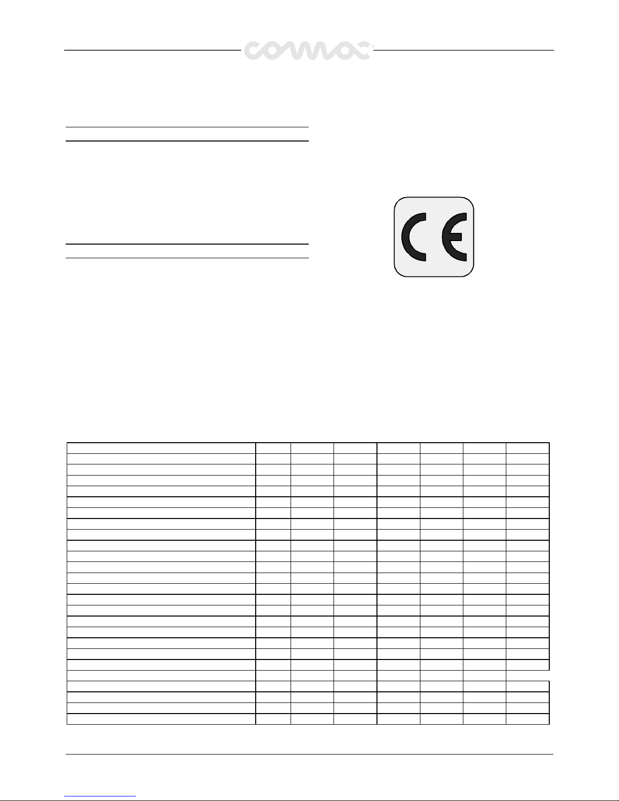
TECHNICAL DATA
TECHNICAL DATATECHNICAL DATA
TECHNICAL DATA U.M.
U.M.U.M.
U.M. SIMPLA45
SIMPLA45SIMPLA45
SIMPLA45 SIMPLA45t
SIMPLA45tSIMPLA45t
SIMPLA45t SIMPLA50
SIMPLA50SIMPLA50
SIMPLA50 SIMPLA50t
SIMPLA50tSIMPLA50t
SIMPLA50t SIMPLA61
SIMPLA61SIMPLA61
SIMPLA61 SIMPLA61t
SIMPLA61tSIMPLA61t
SIMPLA61t
Cleaning width mm 455 455 510 510 610 610
Squeegee width mm 660 660 755 755 755 755
Working capacity, up to sqm/h 1580 1580 1785 1785 2135 2135
Brush diameter mm 1x455 1x455 1x510 1x510 1x610 1x610
Brush speed rpm 250 250 250 250 220 220
Brush pressure kg 25 25 25 25 30 30
Brush motor (power) W 560 560 560 560 560 560
Traction motor (power) W - 150 - 150 - 150
Drive semi-aut. autom. semi-aut. autom. semi-aut. autom.
Movement speed km/h - 0÷3.5 - 0÷3.5 - 0÷3.5
Max. gradient 2% 10% 2% 10% 2% 10%
Suction motor (power) W 350 350 350 350 350 350
Suction vacuum mbar 110 110 110 110 110 110
Solution tank l505050505050
Recovery tank l555555555555
Machine length mm 1300 1300 1300 1300 1400 1400
Machine height mm 1010 1010 1010 1010 1010 1010
Machine width (without squeegee) mm 500 500 560 560 630 630
Voltage V 24 24 24 24 24 24
Batteries Ah/5h 140 140 140 140 140 140
Battery compartment mm 350x380
Batteries weight kg 88 88 88 88 88 88
Machine weight (empty and without batteries) kg 86 93 86 93 100 107
Acoustic radiation pressure level (in conformity with EN dB (A) 70 70 70 70 70 70
Vibration level m/sqs 1.60 1.60 1.60 1.60 1.60 1.60
Page 3
27
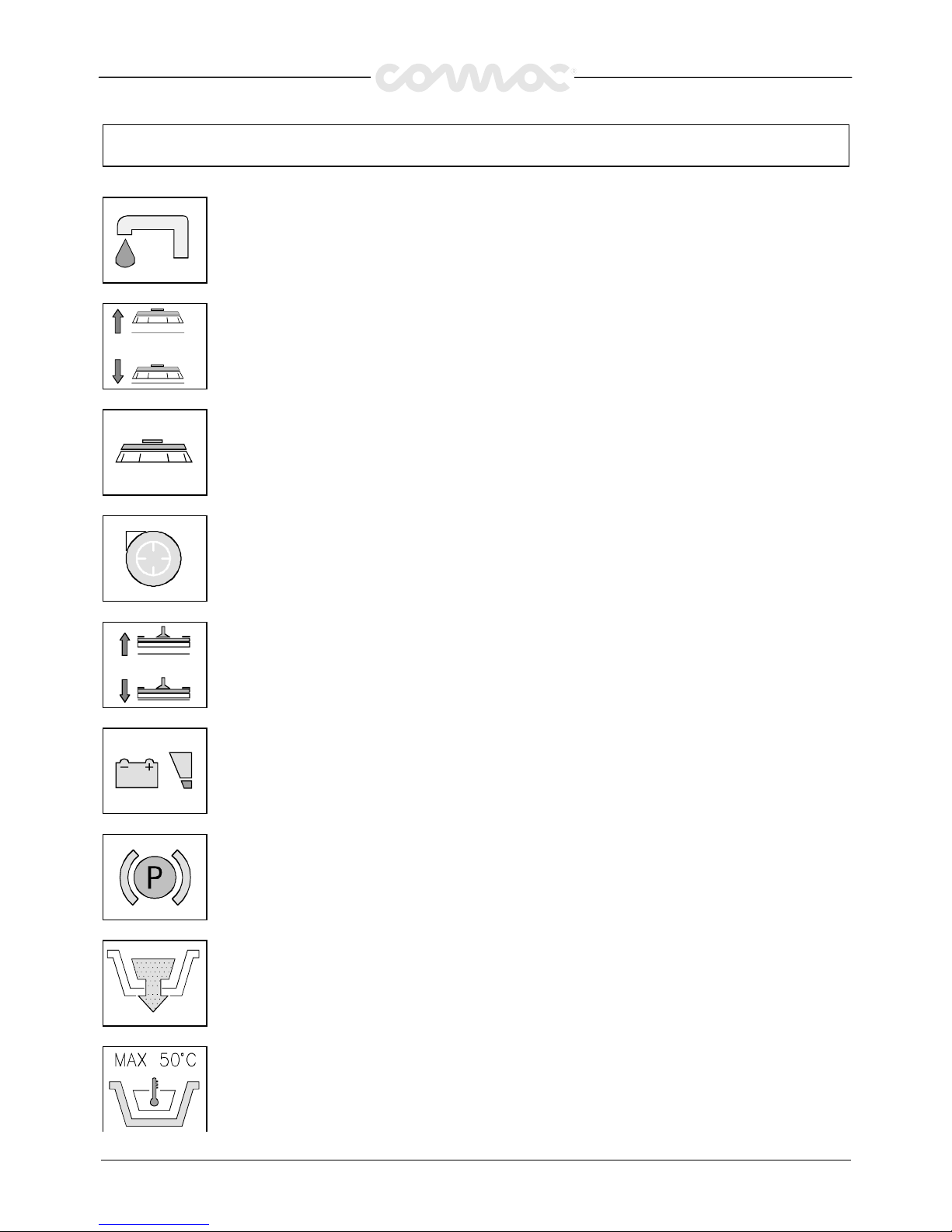
SYMBOLOGY USED ON THE MACHINE
SYMBOLOGY USED ON THE MACHINESYMBOLOGY USED ON THE MACHINE
SYMBOLOGY USED ON THE MACHINE
Symbol denoting cock
Indicates the cock lever
Indicates the solenoid valve switch
Symbol denoting up-down brush base
Indicates the lever of the brush base lifting
Symbol denoting brush
Indicates the brush motor switch
Symbol denoting suction motor
Indicates the suction motor switch
Symbol denoting up - down of the squeegee
Indicates the squeegee lever
Symbol denoting charge level of the batteries
Symbol denoting brake
It is used on top of the emergency and parking brake lever
It is used to indicate the signal lamp of the hand brake on
Indicates the exhaust pipe of the recovery tank
Indication of the maximum temperature of the solution detergent
Placed near the charging hole of the solution tank
Page 4
28
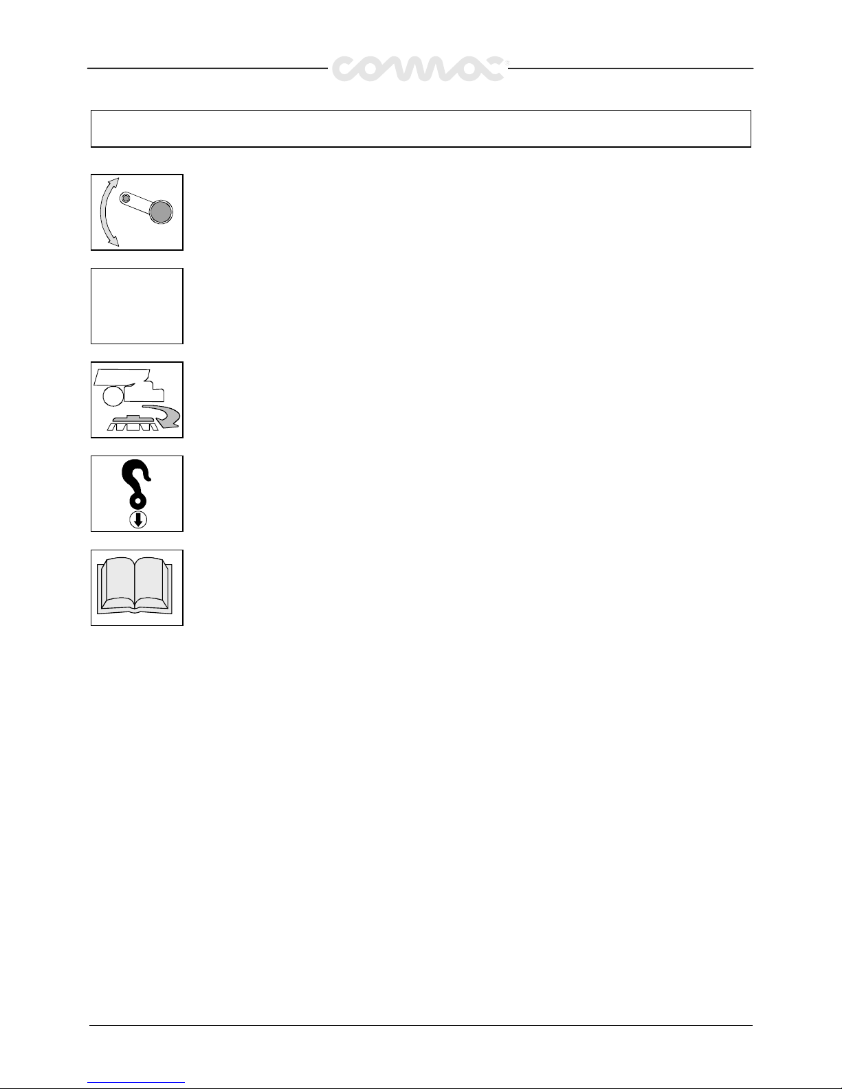
SYMBOLOGY USED ON THE MACHINE
SYMBOLOGY USED ON THE MACHINESYMBOLOGY USED ON THE MACHINE
SYMBOLOGY USED ON THE MACHINE
Indicates the regulation lever for the handle bar height
0/1
0/10/1
0/1
Indicates the general switch
Symbol denoting brush release
Indicates the push button of the brush release
Symbol denoting the coupling
Indicates the anchor points and the load direction
Symbol denoting the open book
Indicates that, the operator has to read the manual before the use of the machine
Page 5
29
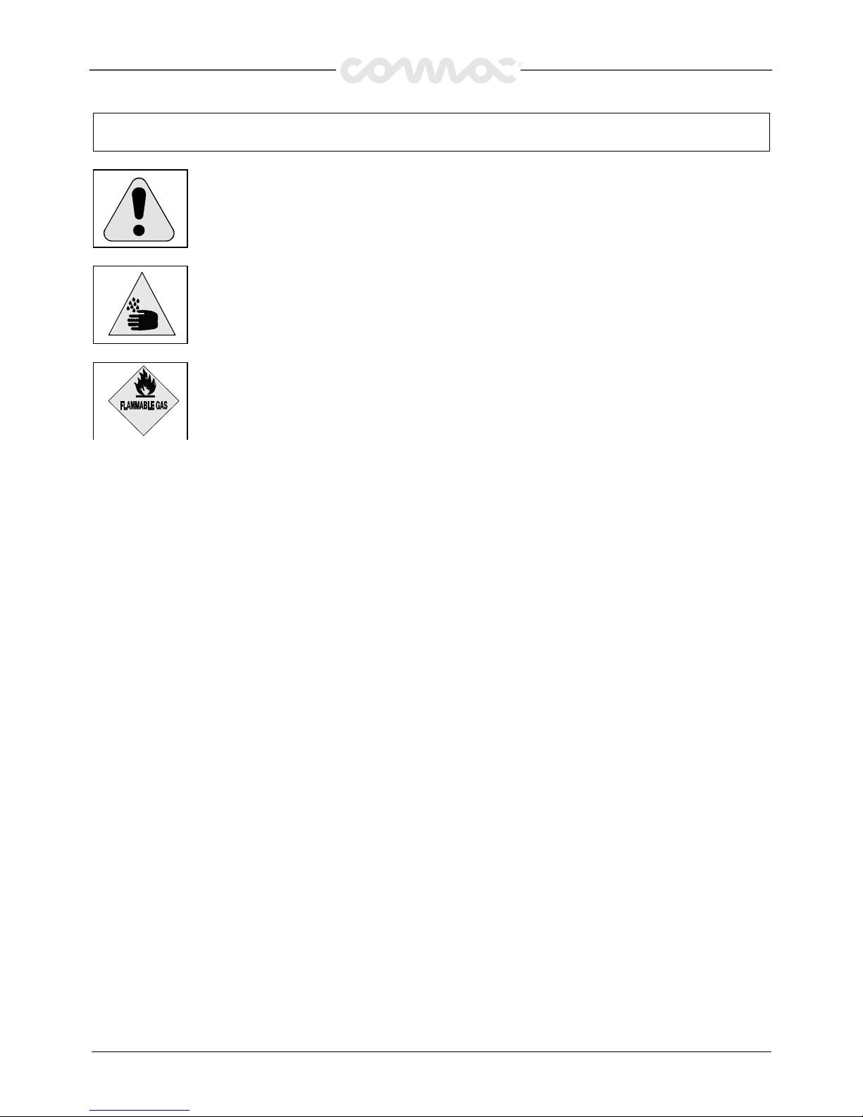
SYMBOLOGY USED IN THE MANUAL
SYMBOLOGY USED IN THE MANUALSYMBOLOGY USED IN THE MANUAL
SYMBOLOGY USED IN THE MANUAL
Symbol denoting a warning
Read carefully the sections preceded by this symbol, for the safety of the operator and of the machine
Indicates danger of gas exhalations and emission of corrosive liquids
Indicates fire danger
Do not approach with free flames
Page 6
30
MACHINE PREPARATION
MACHINE PREPARATIONMACHINE PREPARATION
MACHINE PREPARATION
1.
1.1.
1.
HANDLING OF THE PACKED MACHINE
HANDLING OF THE PACKED MACHINEHANDLING OF THE PACKED MACHINE
HANDLING OF THE PACKED MACHINE
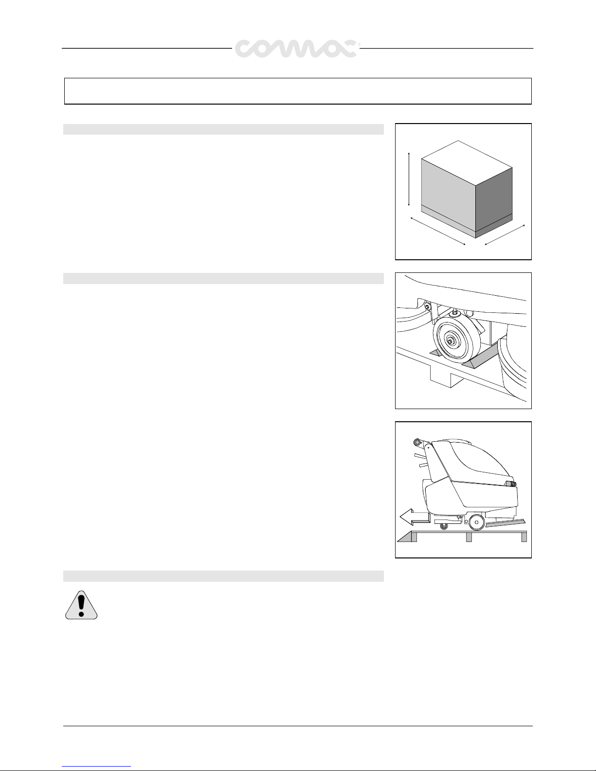
The machine is packed in a specific package provided on a pallet for the handling with
fork trucks. Do not place more than two packages on top of each other.
The total weight is : 105 kg, machines without traction (Simpla 45-50)
115 kg, machines with traction (Simpla 45-50 T)
134 kg, machines without traction (Simpla 61)
144 kg, machines with traction (Simpla 61 T)
The overall dimensions are:
A:
A:A:
A: 1150 mm (Simpla 45-50) A:
A:A:
A: 1280 mm (Simpla 61)
B:
B:B:
B: 610 mm B:
B:B:
B: 760 mm
C:
C: C:
C: 1250 mm C:
C:C:
C: 1520 mm
A
C
B
2.
2.2.
2.
HOW TO UNPACK THE MACHINE
HOW TO UNPACK THE MACHINEHOW TO UNPACK THE MACHINE
HOW TO UNPACK THE MACHINE
1.
Take off the outer package
2.
The machine is fixed on the pallet with wooden wedges which block the wheels
3.
Take off these wedges
4. Using a chute, get the machine down from the pallet, pushing it in reverse motion.
Avoid violent blows to the base.
5.
Keep the pallet for eventual transport necessities
3.
3.3.
3.
CABLE CONNECTION TRACTION MOTOR (machines with traction)
CABLE CONNECTION TRACTION MOTOR (machines with traction) CABLE CONNECTION TRACTION MOTOR (machines with traction)
CABLE CONNECTION TRACTION MOTOR (machines with traction)
WARNING!
WARNING! WARNING!
WARNING! This operation must be carried out by a technician of the
Comac service dept. COMAC
COMAC COMAC
COMAC
Page 7
31
MACHINE PREPARATION
MACHINE PREPARATIONMACHINE PREPARATION
MACHINE PREPARATION
4.
4.4.
4.
INSTALLATION OF THE BATTERIES INTO THE MACHINE
INSTALLATION OF THE BATTERIES INTO THE MACHINE INSTALLATION OF THE BATTERIES INTO THE MACHINE
INSTALLATION OF THE BATTERIES INTO THE MACHINE
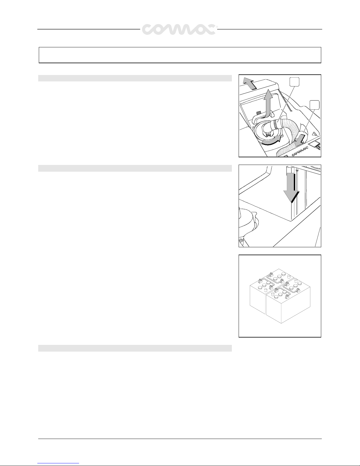
The batteries must be fitted in the suitable compartment under the recovery tank ad they
must moreover satisfy the requirements quoted in the Specification CEI 21-5.
For the battery installation it is necessary to:
1.
Open forward the cover of the recovery tank
2.
Detach the squeegee hose (1) from the recovery tank
3.
Take off the suction plug (2) rotating it counterclockwise
4.
Take off the recovery tank and take care to insert the prop in its position
5.
Place the batteries
1
2
5.
5.5.
5.
BATTERY TYPE
BATTERY TYPE BATTERY TYPE
BATTERY TYPE
For the energy supply use following type of batteries:
lead batteries for traction use with tubular plates and electrolyte free;
or batteries hermetically sealed for traction with gel/gas recombination technology.
DO NOT USE OTHER KIND OF BATTERIES
Every battery is compost out of DIN elements with serial connections and arranged ingroups in two boxes, every group supplies to the holdfasts a voltage of 12V. The
maximum dimensions and the weight of every container are: width 172 mm, length 360
mm, height 285 mm; weight 37,5 Kg.
They have to be moved by suitable means of lifting and transport to weight and
dimension. They have to be coupled using the two handles present at the top of each
box.
They have to be insert in the battery room with the holdfasts in position towards the
posterior part of the machine.
There must be a serial connection between them in order to achieve a voltage of 24V to
the holdfast of the battery. The electric connection process has to be carried out by
specialised persons which were trained by a COMAC service center
6.
6.6.
6.
MAINTENANCE OF THE BATTERY
MAINTENANCE OF THE BATTERYMAINTENANCE OF THE BATTERY
MAINTENANCE OF THE BATTERY
For the maintenance and the recharge follow the instructions given by the constructor of
the batteries.
Pay particular attention to the choose of the battery-charger, which differs according to
the type and capacity of the battery.
Page 8
32
MACHINE PREPARATION
MACHINE PREPARATIONMACHINE PREPARATION
MACHINE PREPARATION
7.
7.7.
7.
DISPOSAL MODALITY
DISPOSAL MODALITY DISPOSAL MODALITY
DISPOSAL MODALITY
When the battery is exhausted let carry out the disconnection by specialised and trained
persons, hook them and lift them with suitable means out of the battery room.
IT IS OBLIGATORY TO HAND OVER THE EXHAUSTED BATTERIES, WHICH ARE
CLASIFIED AS DANGEROUS WASTE, TO A AUTHORIZE INSTITUTION CORRISPONDING
TO THE DISPOSAL LAW.
8.
8.8.
8.
CONNECTION OF THE BATTERY CHARGER
CONNECTION OF THE BATTERY CHARGER CONNECTION OF THE BATTERY CHARGER
CONNECTION OF THE BATTERY CHARGER
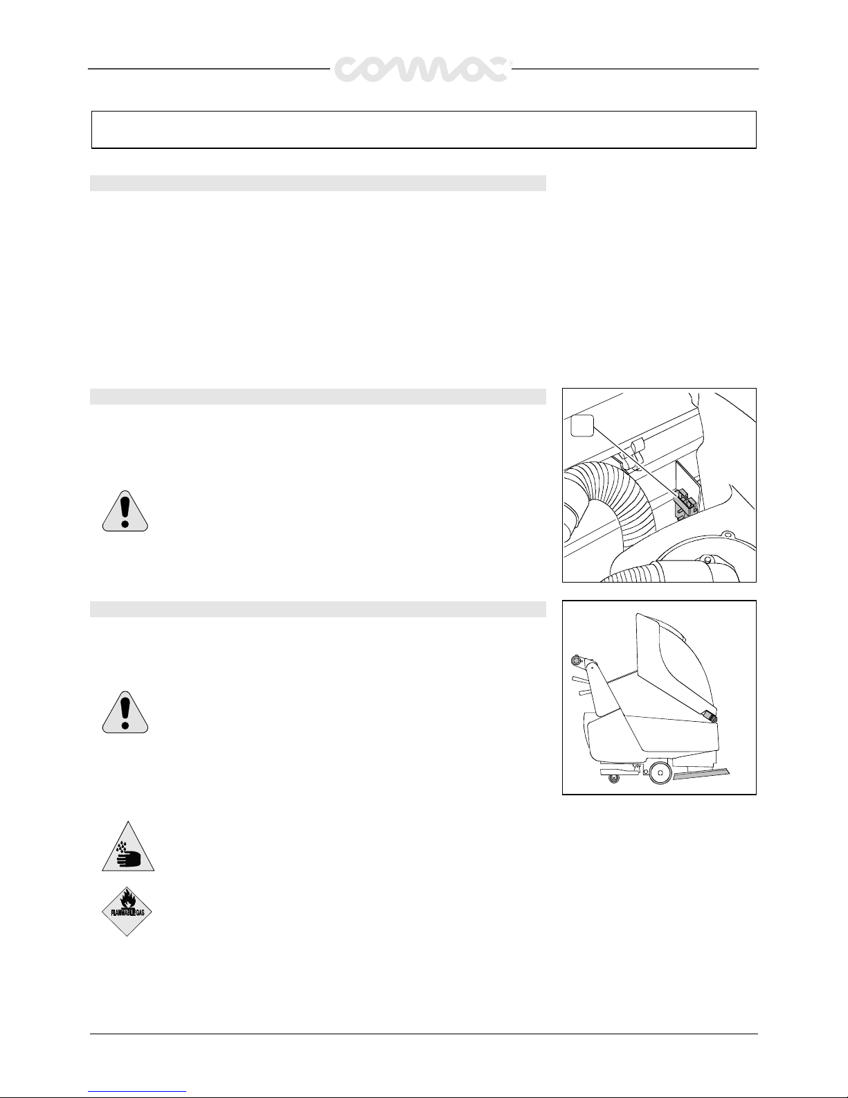
Under the recovery tank cover there is the battery connector (2) in which the connector
of the battery charger has to be inserted. The coupling connector of the battery charger
is delivered in the bag where this instruction booklet is found and must be assembled on
the battery charger cables following the suitable instructions.
ATTENTION!
ATTENTION!ATTENTION!
ATTENTION! This operation must be completed from qualified staff. A
wrong or imperfect connection of cables to the connector can cause to
serious damages to persons or things.
2
9.
9.9.
9.
RECHARGE OF THE BATTERIES
RECHARGE OF THE BATTERIES RECHARGE OF THE BATTERIES
RECHARGE OF THE BATTERIES
In order not TO cause the risk of permanent damages to the batteries, one should at all
costs avoid their complete discharge and effect recharging within a few minutes after
that the signal lamp of discharged batteries begins to blink.
NOTE
NOTENOTE
NOTE: Never leave the batteries completely discharged, even if the
machine is not being used. When recharging the batteries, keep the
recovery tank lifted supporting it with the prop as indicated in figure.
Make sure that the battery charger is suitable for the used batteries
capacity ant type
.
Danger of gas exhalations and emission of corrosive liquids
Danger of gas exhalations and emission of corrosive liquidsDanger of gas exhalations and emission of corrosive liquids
Danger of gas exhalations and emission of corrosive liquids
Fire danger
Fire dangerFire danger
Fire danger
Do not approach with free flames
Do not approach with free flamesDo not approach with free flames
Do not approach with free flames
Page 9
33
MACHINE PREPARATION
MACHINE PREPARATIONMACHINE PREPARATION
MACHINE PREPARATION
10.
10.10.
10.
CONNECTION OF THE BATTERY CONNECTOR
CONNECTION OF THE BATTERY CONNECTOR CONNECTION OF THE BATTERY CONNECTOR
CONNECTION OF THE BATTERY CONNECTOR
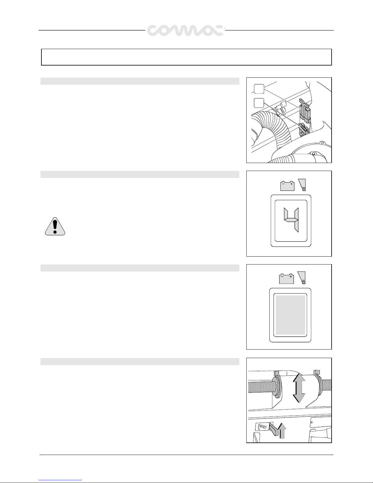
The battery connector (2) has to be connected to the connector of the machine (1)
2
1
11.
11.11.
11.
BATTERIES’ INDICATOR (machines with traction)
BATTERIES’ INDICATOR (machines with traction)BATTERIES’ INDICATOR (machines with traction)
BATTERIES’ INDICATOR (machines with traction)
The batteries’ indicator is digital with 4 fixed positions and a blinking one. The
numbers, which appear on the display, show the approximate charge level.
4444 = maximum charge, 3333 = charge 3/4, 2222 = charge 2/4, 1111 = charge 1/4,
0000 = (blinking) discharged batteries)
WARNING!
WARNING! WARNING!
WARNING! Some seconds after that “0” blinks, the brush motor
automatically switches off. Anyway, the machine can finish to dry before
recharging the batteries.
12.
12.12.
12.
BATTERIES’ INDICATOR (machines without traction)
BATTERIES’ INDICATOR (machines without traction)BATTERIES’ INDICATOR (machines without traction)
BATTERIES’ INDICATOR (machines without traction)
The batteries’ indicator is a green signal lamp, which remains always on until the
batteries are charged. When the signal lamp begins to blink, it is necessary to proceed
with the recharge of the batteries.
13.
13.13.
13.
HEIGHT HANDLE BAR
HEIGHT HANDLE BAR HEIGHT HANDLE BAR
HEIGHT HANDLE BAR
The handle bar is adjustable in three different positions:
1.
Release the lever
2.
Put the handle bar at the desired height, compatibly with the clamping holes
3.
Release the lever
Page 10
34
MACHINE PREPARATION
MACHINE PREPARATIONMACHINE PREPARATION
MACHINE PREPARATION
14.
14.14.
14.
SQUEEGEE ASSEMBLY
SQUEEGEE ASSEMBLY SQUEEGEE ASSEMBLY
SQUEEGEE ASSEMBLY
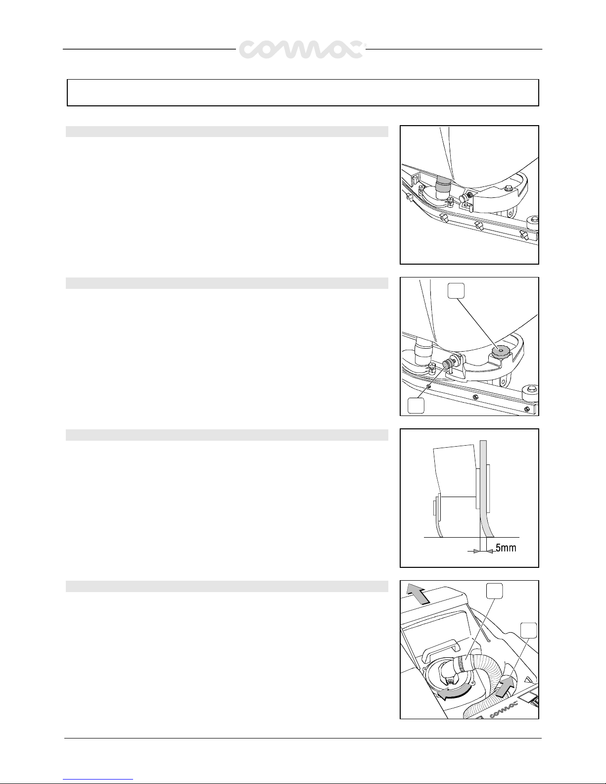
The squeegee, which is packed separately from the machine, should be assembled as
shown in the figure, threading the stud bolt in the coupling until the release of the lever.
Fit the squeegee hose into its coupling, paying attention that the hose has to pass on
the right side from the lifting cable.
15.
15.15.
15.
ADJUSTMENT SQUEEGEE HEIGHT
ADJUSTMENT SQUEEGEE HEIGHT ADJUSTMENT SQUEEGEE HEIGHT
ADJUSTMENT SQUEEGEE HEIGHT
The squeegee has to be regulated depending on the wearing of the rubbers. To adjust
this, rotate the knob (2) counterclockwise to lift the squeegee and clockwise to lower it.
Note:
Note:Note:
Note: The right and left wheels must be adjusted at the same amount so that the
squeegee works in parallel to the floor.
2
1
16.
16.16.
16.
ADJUSTMENT SQUEEGEE INCLINATION
ADJUSTMENT SQUEEGEE INCLINATION ADJUSTMENT SQUEEGEE INCLINATION
ADJUSTMENT SQUEEGEE INCLINATION
During working operation, the rear rubber has to work slightly tilted backwards and this
equally in its whole length for about 5mm. Should it be necessary to increase the
rubber bending in the central part, then tilt the squeegee body backwards and turn
the adjuster (1) counterclockwise. If the rubber bending is to be noticeable at the sides
of the squeegee, turn the adjuster clockwise. At the end of the adjustment, block the
adjuster nut.
17.
17.17.
17.
RECOVERY TANK
RECOVERY TANK RECOVERY TANK
RECOVERY TANK
Open the cover and check that, the suction plug (2) is properly blocked by fitting the
notches in its proper seat rotating it clockwise and that it is connected regularly to the
hose which goes to the suction motor.
Check furthermore that, the squeegee hose (1) is properly placed in their seats and that
the plug of the exhaust pipe, which is located in the front part of the machine, is closed.
1
2
Page 11
35
MACHINE PREPARATION
MACHINE PREPARATIONMACHINE PREPARATION
MACHINE PREPARATION
18.
18.18.
18.
SOLUTION TANK
SOLUTION TANK SOLUTION TANK
SOLUTION TANK
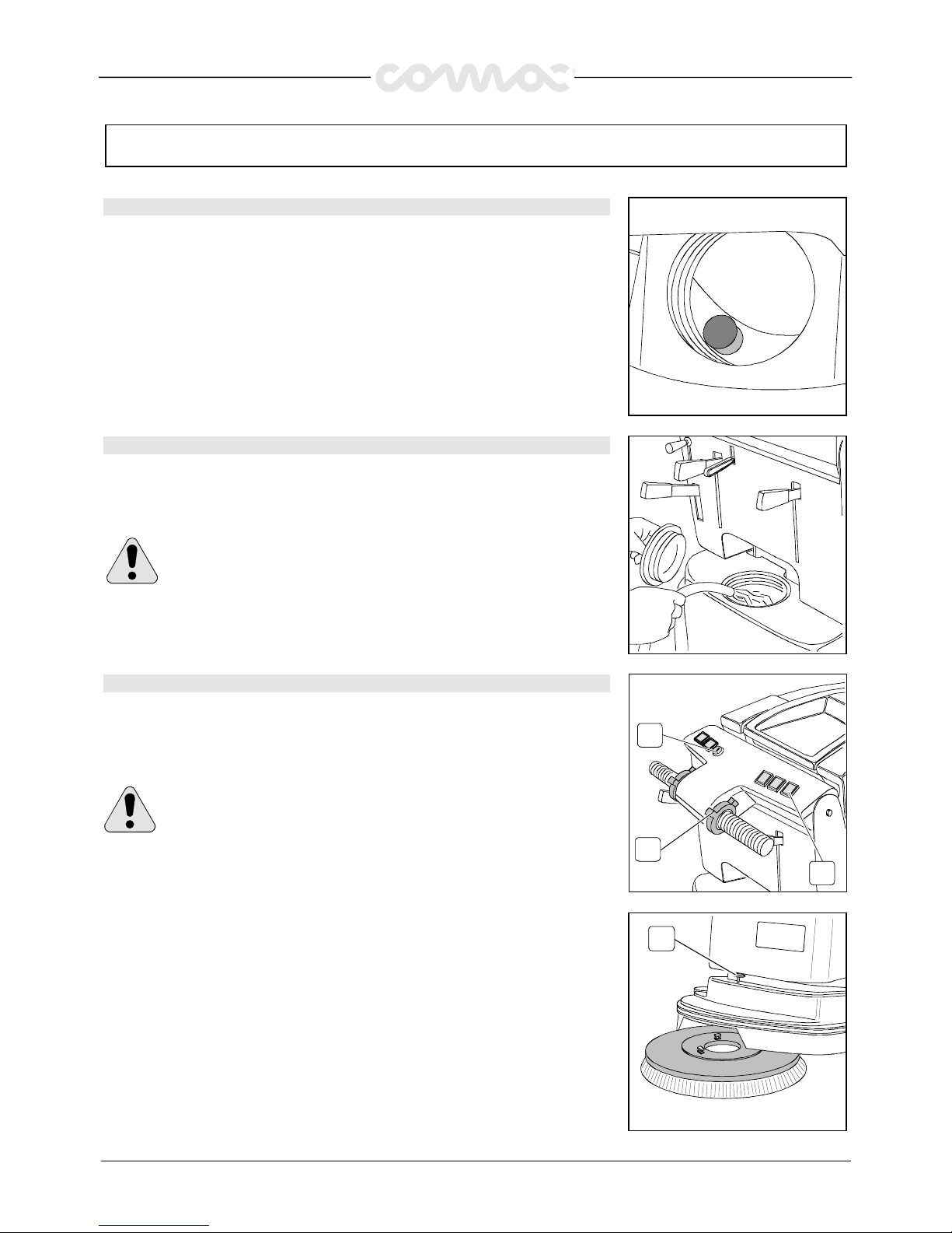
Take off the water inlet plug and check that, the solution filter, placed on the left bottom
side, has been assembled properly.
19.
19.19.
19.
SOLUTION WATER
SOLUTION WATERSOLUTION WATER
SOLUTION WATER
Fill the solution tank with clean water at a temperature not more than 50
°C and add
liquid detergent in the proper concentration following the instructions of the
manufacturer. Excess foam could damage the suction motor, so use only the minimum
amount of detergent necessary. Reassemble the cover.
WARNING!
WARNING!WARNING!
WARNING! Always use low foam detergent. To avoid the production of
foam, before starting to clean, put a minimum quantity of antifoam liquid
into the recovery tank. Never use pure acid
Never use pure acid Never use pure acid
Never use pure acid
20.
20.20.
20.
BRUSH ASSEMBLY
BRUSH ASSEMBLY BRUSH ASSEMBLY
BRUSH ASSEMBLY
1.
With the brush base in lifted position, insert the brush placing it in correspondence
with the plate under the brush base.
2.
Lower the brush base, turn the key (1) into position ON, press the brush switch (2),
push the lever (3) on the handle bar. At this point the brush is coupled.
WARNING!
WARNING!WARNING!
WARNING! During this operation make sure that, there are not any
objects or persons close to the brush.
1
3
2
3. Adjust, through the knob (1), the height of the splash guard rubber so that it touch
the floor.
The adjustment has to be repeated regularly depending on the brush wear.
1
Page 12

36
GENERAL RULES OF SECURITY
GENERAL RULES OF SECURITYGENERAL RULES OF SECURITY
GENERAL RULES OF SECURITY
The rules below have to be followed carefully in order to avoid damages to the operator and to the machine.
The rules below have to be followed carefully in order to avoid damages to the operator and to the machine.The rules below have to be followed carefully in order to avoid damages to the operator and to the machine.
The rules below have to be followed carefully in order to avoid damages to the operator and to the machine.
r
Read the labels carefully on the machine. Do not cover them for any reason and replace them immediately if damaged
r
The machine must be used exclusively by authorized staff that has been instructed for its use
r
During the working of the machine, pay attention to other people and especially to the children
r
Do not mix different detergents, avoiding harmful odours
r
Do not place any liquid containers onto the machine
r
The storage temperature has to be between - 25° C and + 55° C
r
Operating conditions: room temperature between 0°C and 40°C with respective humidity between 30 and 95%
r
Do not use the machine in explosive atmosphere
r
Do not use the machine as a means of transport
r
Do not use acid solutions which could damage the machine and/or the persons
r
Avoid working with the brush when the machine stands still, in order to prevent floor damages
r
Do not vacuum inflammable liquids
r
This appliance is not suitable for picking up hazardous dust
r
In case of fire, use a powder extinguisher. Do not use water
r
Do not strike shelvings or scaffoldings, where
r
there is danger of falling objects
r
Adapt the utilization speed to the adhesion conditions
r
ATTENTION!
ATTENTION!ATTENTION!
ATTENTION! Do not use the machine on areas having a higher gradient than the one stated on the number plate
r
When the machine is in parking position, take off the key and insert the parking brake
r
The machine has to carry out simultaneously the operations of washing and drying. Different operations have to be carried out
in areas which are not permitted for the passage of non employed staff. Signal the areas of moist floors with suitable signs
r
If the machine does not work properly, check by conducting simple maintenance procedures. Otherwise, it is better to ask for
COMAC
COMACCOMAC
COMAC technical service
r
Where parts are required, ask for ORIGINAL spare parts to an agent and/or to an authorized COMAC
COMACCOMAC
COMAC dealer
r
Use only original COMAC
COMAC COMAC
COMAC brushes indicated in the paragraph “CHOICE AND USE OF BRUSHES”
r
In case of danger act immediately upon the emergency brake
r
For any cleaning and maintenance operation take off the power supply from the machine
r
Do not take off the pieces which require the use of tools to be removed
r
To restore all the connections electrical workers after whichever maintenance operation
r
Do not wash the machine with direct water jets or with high water pressure nor with corrosive material
r
Every 200 working hours have a machine check through a COMAC
COMACCOMAC
COMAC service department
r
In order to avoid scales on the solution tank filter, do not fill the detergent solution many hours before the machines’ use
r
Before using the machine, check that all doors and coverings are in their position as indicated in this use and maintenance
catalogue
r
Be sure the recovery tank is empty before removing it
r
Provide for the scrapping of the material of normal wear following strictly the respective rules
r
When, after years of precious work, your COMAC
COMACCOMAC
COMAC machine has to be abandoned, provide for the scrapping in appropriate
centres, because of the presence of toxic-harmful materials, especially oils, batteries and electronic components, and
considering that the machine itself has been constructed using materials integrally recyclable.
Page 13
37
PERFORMANCE
PERFORMANCEPERFORMANCE
PERFORMANCE
SETTING FOR WORK
SETTING FOR WORKSETTING FOR WORK
SETTING FOR WORK
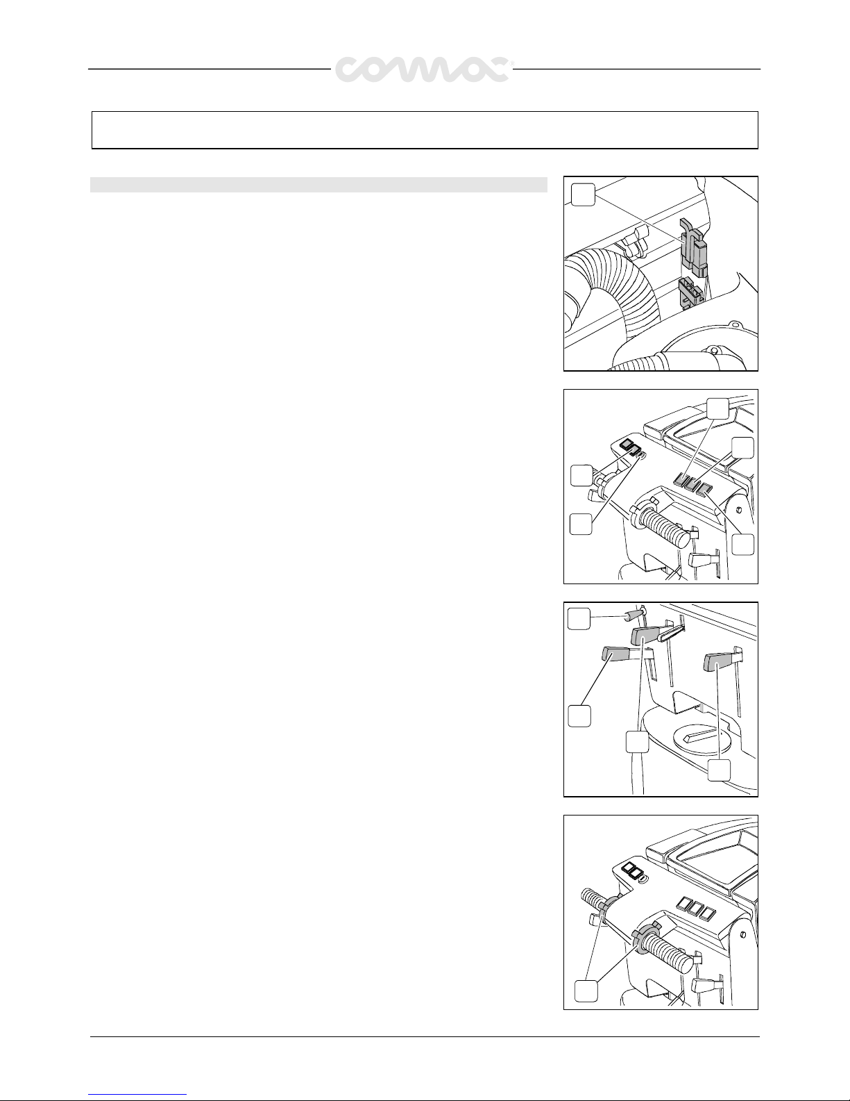
1.
Connect the connector (1) to the batteries
1
2. Turn the key of the general switch (2) into position “1” (clockwise). Immediately, the
signal lamp comes on (3).
3.
Press the solenoid valve switch (4)
4.
Press the suction motor switch (5)
5.
Press the brush switch (6)
6
5
4
3
2
6. Acting upon the cock lever (1) adjust the quantity of the detergent solution which has
to be sufficient to wet the floor uniformly but not too much to get out of the
splashguard. Please keep in mind that, the correct solution quantity depends always
on the type of floor, the dirt and the speed.
7.
Release the lever (2) and lower the brush base
8.
Lower the squeegee acting upon the lever (3)
9.
Check that the parking brake (4) is released
1
4
3
2
10. Pushing forward the lever (1) on the handle bar, the machine begins to move. During
the first metres of operating, check that the quantity of the detergent solution is
sufficient and that the squeegee dries perfectly.
The machine will now start working efficiently until the detergent solution runs out.
1
Page 14
38
PERFORMANCE
PERFORMANCEPERFORMANCE
PERFORMANCE
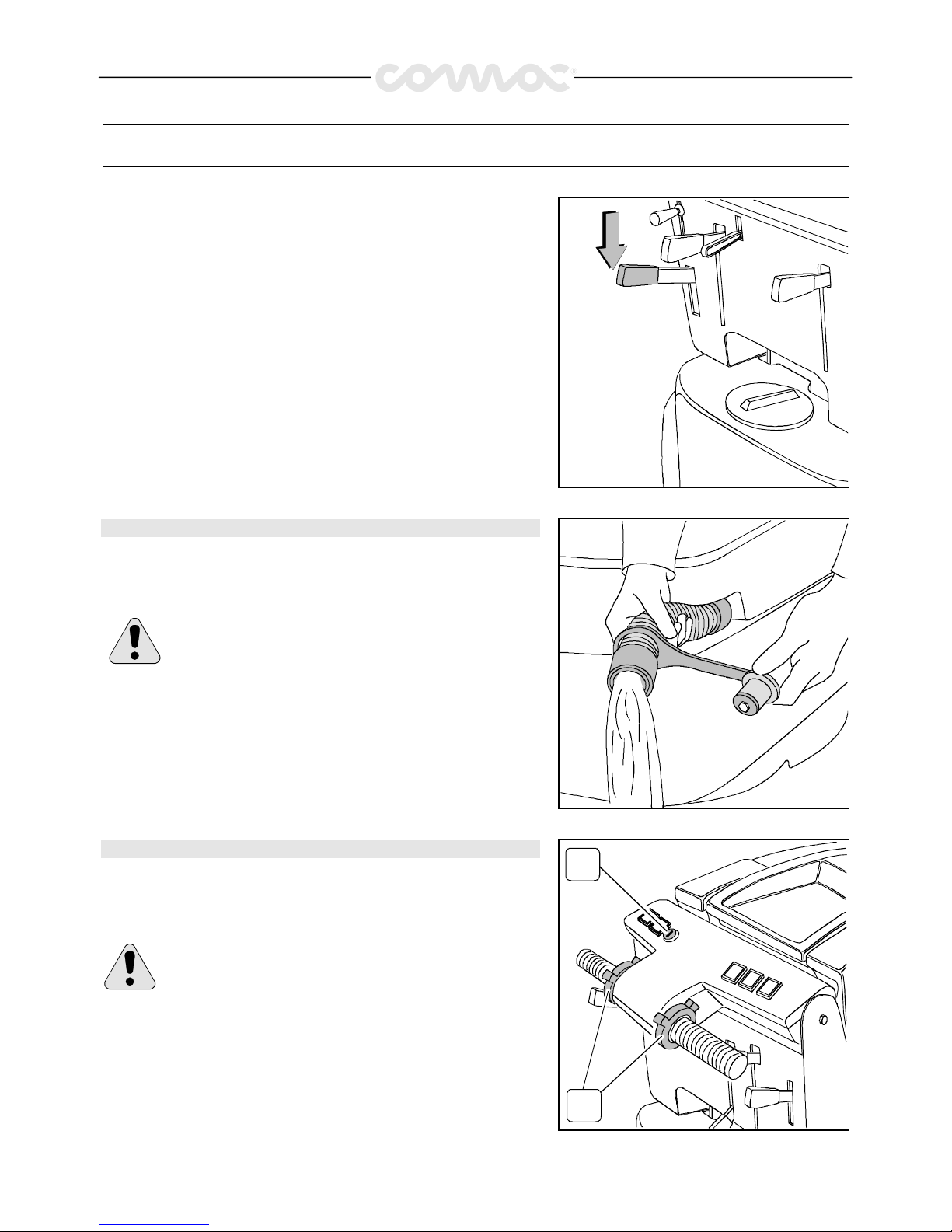
Whenever problems during operating should arise, release the lever and
push immediately the emergency brake placed on the left side. This
command will block the traction of the machine. To restart the machine
again, once the problem has been solved, release the lever of the parking
brake and push forward the lever on the handle bar.
DEVICE TOO FULL
DEVICE TOO FULLDEVICE TOO FULL
DEVICE TOO FULL
The machine is equipped with a float, which intervenes when the recovery
tank is full causing the closure of the suction hose. In this case, it is
necessary to proceed with the emptying of the recovery tank taking off the
plug of the exhaust pipe.
WARNING!
WARNING! WARNING!
WARNING! This operation has to be carried out using gloves
to protect from contact with dangerous solutions
.
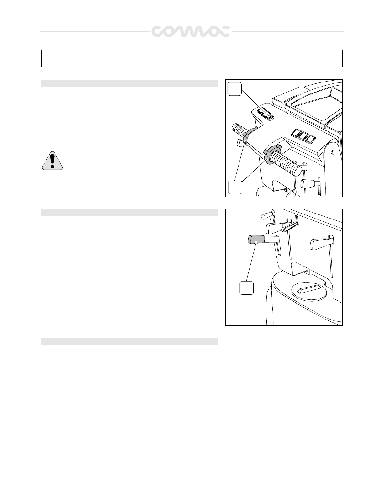
MOVEMENT (machines without traction)
MOVEMENT (machines without traction)MOVEMENT (machines without traction)
MOVEMENT (machines without traction)
The traction of these machines is obtained through the brush, which works
slightly inclined, so that the machine is being dragged forward. To move the
machine, it is necessary to act upon the key (1), wait for 3 seconds and
then rotate forward (forward movement) the lever (2) on the handle bar.
WARNING!
WARNING! WARNING!
WARNING! When carrying out even short backward
movements, make sure that the squeegee is lifted
.
2
1
Page 15
39
PERFORMANCE
PERFORMANCEPERFORMANCE
PERFORMANCE
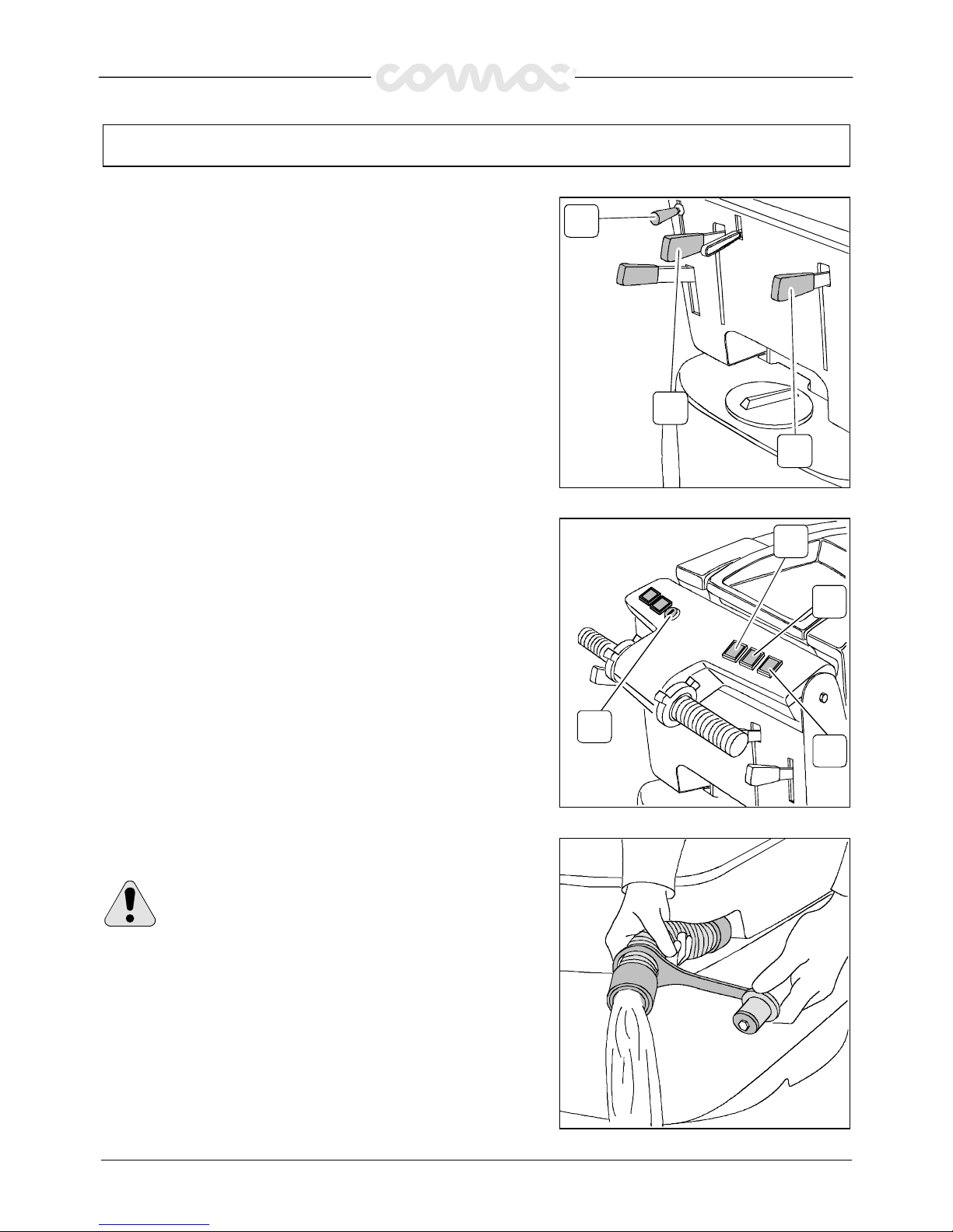
MOVEMENT (machines with traction)
MOVEMENT (machines with traction)MOVEMENT (machines with traction)
MOVEMENT (machines with traction)
These machines are equipped with electronically commanded traction, with
two speeds forwards and one backwards.
To move the machine, it is necessary to act upon the key (1), wait for three
seconds and then rotate forward (forward movement) or backward (rear
movement) the lever (2) on the handle bar. Pushing forward the lever a few
millimetres, the first speed is available, pushing the lever forward
completely, the second speed is obtained.
In reverse motion, the speed movement is reduced.
WARNING!
WARNING! WARNING!
WARNING! When carrying out even short backward
movements, make sure that the squeegee is lifted
.
2
1
BRAKE (machines without traction)
BRAKE (machines without traction)BRAKE (machines without traction)
BRAKE (machines without traction)
The machine is equipped with a braking system controlled through the left
lever (1), which is used as a parking and emergency brake.
1
BRAKE (machines with traction)
BRAKE (machines with traction)BRAKE (machines with traction)
BRAKE (machines with traction)
The machine is equipped with an electronical brake system. To brake in
normal working conditions, it is enough to release the lever on the handle
bar.
In case of need (stop, danger, etc. …), act upon the mechanical brake
pushing downwards the lever (1).
Page 16
40
ON COMPLETION OF THE WORK
ON COMPLETION OF THE WORKON COMPLETION OF THE WORK
ON COMPLETION OF THE WORK
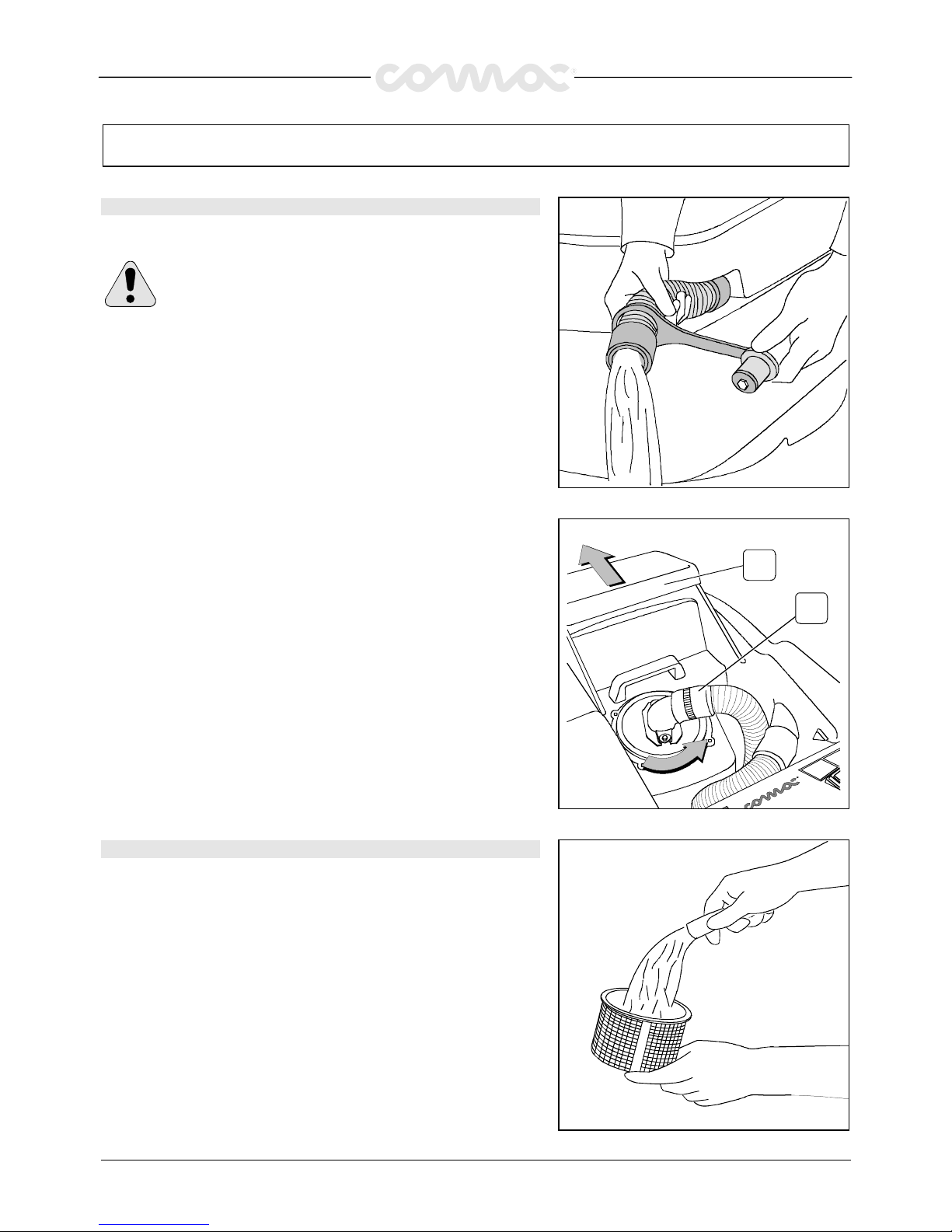
Having finished the job and before any type of maintenance is done:
1.
Close the cock through the lever (1)
2.
Raise the brush base through the lever (2)
3.
Raise the squeegee through the lever (3)
1
3
2
4. Switch off the solenoid valve switch (1)
5.
Switch off the brush switch (2)
6.
Switch off the suction motor switch (3)
7.
Bring the machine up to the place provided for the water outlet
8.
Turn the key (4) into position “0” (counterclockwise)
9.
Insert the parking brake
2
3
1
4
10. Extract the hose placed on the front part of the recovery tank
11.
Unscrew the exhaust plug and empty the tank
WARNING!
WARNING! WARNING!
WARNING! This operation has to be carried out using gloves
to protect from contact with dangerous solutions.
12.
Take off the brush and clean it with a water jet (for the brush
disassembly please read further on under “DISASSEMBLY OF THE
BRUSH”)
Page 17
41
DAILY MAINTENANCE
DAILY MAINTENANCEDAILY MAINTENANCE
DAILY MAINTENANCE
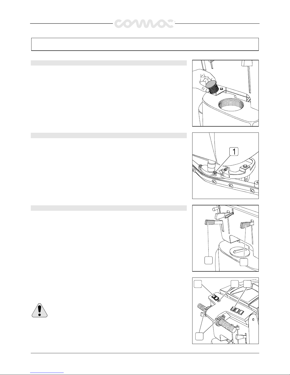
CLEANING RECOVERY TANK
CLEANING RECOVERY TANKCLEANING RECOVERY TANK
CLEANING RECOVERY TANK
1.
Extract the hose placed on the front part of the recovery tank
2.
Unscrew the exhaust plug and empty the tank
WARNING!
WARNING!WARNING!
WARNING! This operation has to be carried out using gloves
to protect from contact with dangerous solutions.
3. Lift the cover of the recovery tank (1)
4.
Take off the suction plug (2) rotating it counterclockwise
5.
Take off the filter and its protection
6.
Rinse everything with a water jet
1
2
CLEANING OF THE SUCTION FILTER
CLEANING OF THE SUCTION FILTERCLEANING OF THE SUCTION FILTER
CLEANING OF THE SUCTION FILTER
1.
Lift the cover
2.
Take off the suction plug by rotating it counterclockwise
3.
Take off the filter
4.
With a water jet clean the walls and the bottom of the filter
5.
Wash thoroughly all components
6.
Reassemble everything
Page 18
42
DAILY MAINTENANCE
DAILY MAINTENANCEDAILY MAINTENANCE
DAILY MAINTENANCE
CLEANING SOLUTION FILTER
CLEANING SOLUTION FILTERCLEANING SOLUTION FILTER
CLEANING SOLUTION FILTER
1.
Unscrew the plug on the solution tank
2.
Take off the filter pulling the cap upwards and clean it thoroughly
3.
Reassemble everything pushing the cap up to the snap on the filter body
CLEANING OF THE SQUEEGEE
CLEANING OF THE SQUEEGEECLEANING OF THE SQUEEGEE
CLEANING OF THE SQUEEGEE
In order to have the best drying results, check that the squeegee is always clean.
To clean the squeegee it is necessary to:
1.
Take off the hose from the squeegee
2.
Loosen the knobs (1) as indicated
3.
Take off the opening and clean it
4.
Clean the inside of the squeegee thoroughly
5.
Clean the squeegee rubbers thoroughly
6.
Reassemble everything once more
DISASSEMBLY OF THE BRUSH
DISASSEMBLY OF THE BRUSHDISASSEMBLY OF THE BRUSH
DISASSEMBLY OF THE BRUSH
This machine is equipped with an automatic brush release system, to avoid troublesome
operating procedures. Go ahead as follows:
1.
Lift the brush base acting upon the lever (1)
2.
Brake the machine acting upon the lever (2)
1
2
3. Turn the key (1) into position “1”, press the brush switch (2); keeping the release
button (4) pressed, push for an instant the lever on the handle bar (3) ad then
release it.
The brush will move for a few instants and will fall at once under the cover.
WARNING!
WARNING!WARNING!
WARNING! During this operation make sure that, there are not any objects
or persons close to the brush.
3
4
1 2
Page 19
43
DAILY MAINTENANCE
DAILY MAINTENANCEDAILY MAINTENANCE
DAILY MAINTENANCE
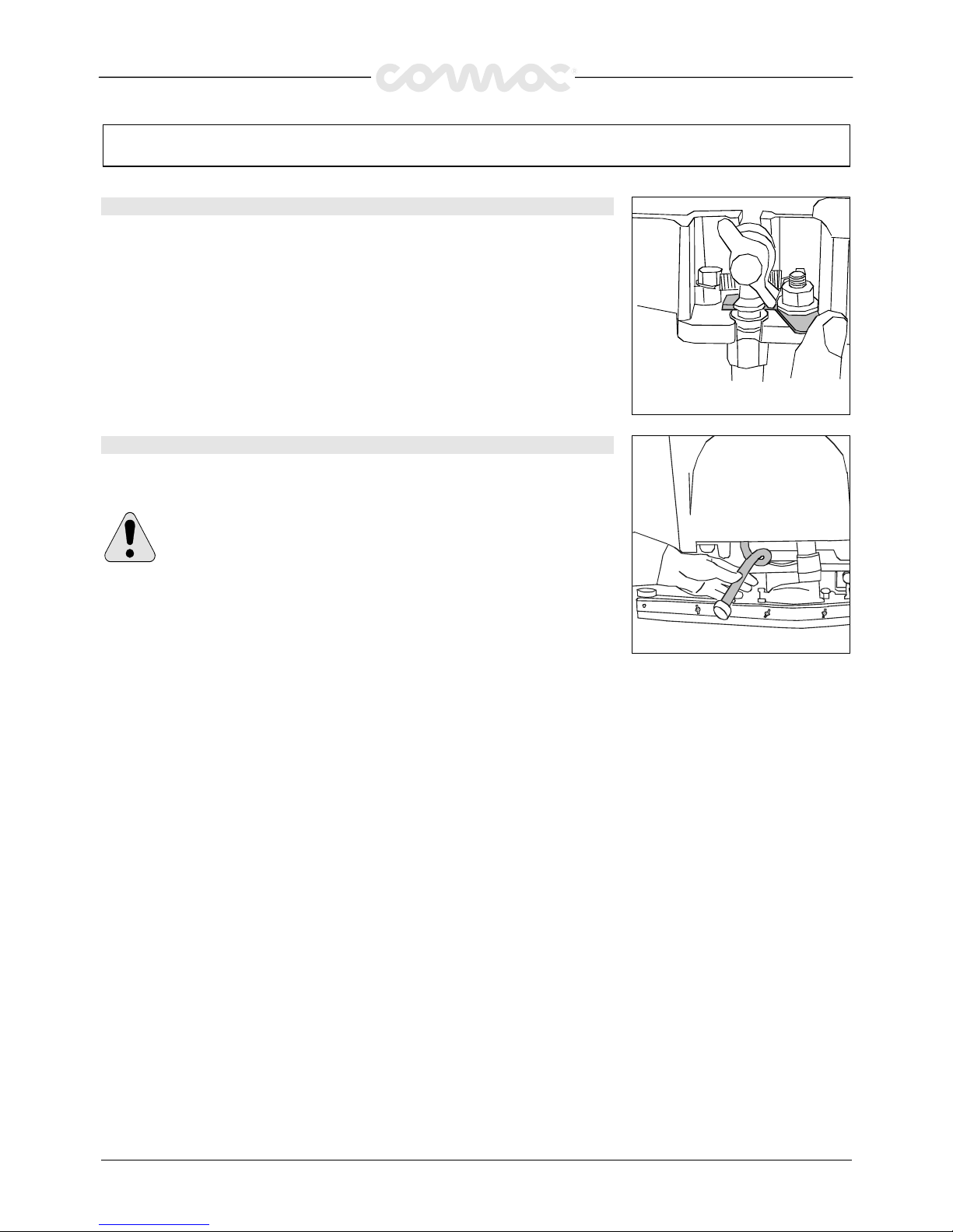
REPLACEMENT OF THE SQUEEGEE RUBBERS
REPLACEMENT OF THE SQUEEGEE RUBBERSREPLACEMENT OF THE SQUEEGEE RUBBERS
REPLACEMENT OF THE SQUEEGEE RUBBERS
Check the squeegee rubbers wear and if necessary, change them.
To replace them:
1.
Take off the squeegee hose from its coupling
2.
Push the rocker arm of uncoupling and parade the stud bolt skilful
3.
Remove the squeegee from its support
4.
Loosen the nuts which block the rubber blades and take them off
5.
Replace the rubbers
6.
To reassemble the squeegee repeat the above-mentioned operations inversely
CLEANING OF
CLEANING OF CLEANING OF
CLEANING OF THE BATTERY COMPARTMENT
THE BATTERY COMPARTMENTTHE BATTERY COMPARTMENT
THE BATTERY COMPARTMENT
To empty the battery compartment from possible liquids, use the suitable hose placed
under the solution tank and accessible from the rear part of the machine
.
ATTENTION!
ATTENTION!ATTENTION!
ATTENTION! This operation has to be carried out using gloves to protect
from contact with dangerous solutions. Danger of emission of corrosive
Danger of emission of corrosiveDanger of emission of corrosive
Danger of emission of corrosive
liquids. Fire danger: do
liquids. Fire danger: doliquids. Fire danger: do
liquids. Fire danger: do not approach with free flames.
not approach with free flames.not approach with free flames.
not approach with free flames.
Page 20
44
WEEKLY MAINTENANCE
WEEKLY MAINTENANCEWEEKLY MAINTENANCE
WEEKLY MAINTENANCE
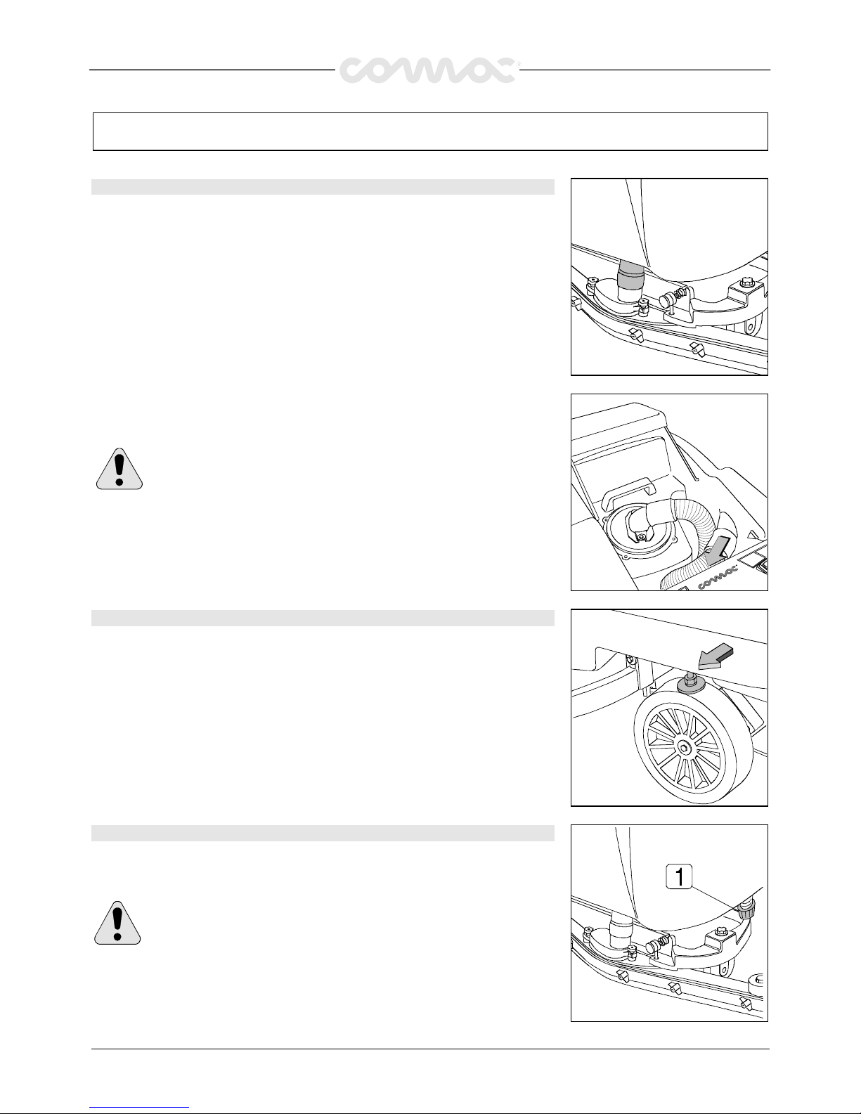
CLEANING OF THE SQUEEGEE HOSE
CLEANING OF THE SQUEEGEE HOSECLEANING OF THE SQUEEGEE HOSE
CLEANING OF THE SQUEEGEE HOSE
Weekly or whenever suction seems to be unsatisfactory check that the squeegee hose is
not obstructed. Eventually, clean it proceeding as follows:
1.
Take off the hose from its coupling on the squeegee
2.
Take off the other end from the recovery tank
3. Wash the inner part of the hose with a water jet introduced from the side where it is
being connected to the tank
4.
To reassemble the hose repeat the above-mentioned operations inversely
WARNING!
WARNING! WARNING!
WARNING! Do not wash the hose, which goes from the suction motor to
the suction plug.
CHECK BRAKE
CHECK BRAKECHECK BRAKE
CHECK BRAKE
Once a week check the distance between the brake pads and the wheels. Eventually,
adjust them through the nuts bringing them back to a distance of 3mm in resting
conditions.
CLEANING SOLUTION TANK
CLEANING SOLUTION TANKCLEANING SOLUTION TANK
CLEANING SOLUTION TANK
1.
Unscrew the plug on the solution tank
2.
Rinse with a water jet
3.
Unscrew the exhaust plug (1) and empty the tank
WARNING!
WARNING!WARNING!
WARNING! This operation has to be carried out using gloves to protect
from contact with dangerous solutions.
Page 21
45
TROUBLE SHOOTING GUIDE
TROUBLE SHOOTING GUIDETROUBLE SHOOTING GUIDE
TROUBLE SHOOTING GUIDE
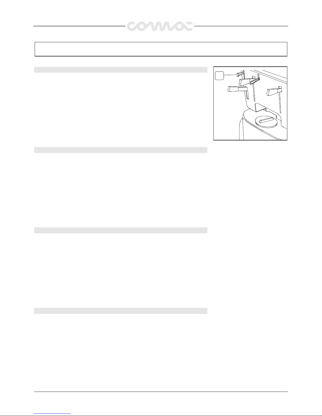
INSUFFICIENT WATER ONTO THE BRUSH
INSUFFICIENT WATER ONTO THE BRUSHINSUFFICIENT WATER ONTO THE BRUSH
INSUFFICIENT WATER ONTO THE BRUSH
1.
Make sure that the cock (1) is open
2.
That there is water in the solution tank
3.
Make sure that the solenoid valve switch is on
1
THE MACHINE DOES NOT CLEAN SATISFACTORILY
THE MACHINE DOES NOT CLEAN SATISFACTORILYTHE MACHINE DOES NOT CLEAN SATISFACTORILY
THE MACHINE DOES NOT CLEAN SATISFACTORILY
1.
Check the condition of the brush and replace it, if necessary (the brush has to be
replaced when the bristles reach around 15mm)
2.
Use a different kind of brush to the one fitted as standard. For cleaning operations on
floors where the dirt proves to be particularly resistant, we recommend using special
brushes that may be supplied optionally according to needs (see under “CHOICE
AND USE OF BRUSHES”).
THE SQUEEGEE DOES NOT DRY PERFECTLY
THE SQUEEGEE DOES NOT DRY PERFECTLYTHE SQUEEGEE DOES NOT DRY PERFECTLY
THE SQUEEGEE DOES NOT DRY PERFECTLY
1.
Check that the squeegee rubbers are clean
2.
Adjust the inclination of the squeegee (see under “SQUEEGEE” in “MACHINE
PREPARATION”)
3.
Check that the suction hose is correctly fitted in its housing on the recovery tank
4.
Take off the entire suction assembly and clean it
5.
Replace the rubbers, if worn
6.
Check that the suction motor switch is on
7.
Check the adjustment of the wheels
EXCESSIVE FOAM PRODUCTION
EXCESSIVE FOAM PRODUCTIONEXCESSIVE FOAM PRODUCTION
EXCESSIVE FOAM PRODUCTION
Check that a low foam detergent has been used. If required, add a small quantity of
antifoam liquid into the recovery tank.
Remember that, when the floor is not very dirty, more foam is generated. In this case
dilute more the detergent.
Page 22

46
CHOICE AND USE OF BRUSHES
CHOICE AND USE OF BRUSHESCHOICE AND USE OF BRUSHES
CHOICE AND USE OF BRUSHES
POLYPROPYLENE BRUSH (PPL)
POLYPROPYLENE BRUSH (PPL)POLYPROPYLENE BRUSH (PPL)
POLYPROPYLENE BRUSH (PPL)
It is used on all types of floors which are hot water resistant (not more than 60
°C). The Polypropylene brush is nonhygroscopic
and therefore conserves its characteristics even if working in the wet conditions.
NYLON BRUSH
NYLON BRUSHNYLON BRUSH
NYLON BRUSH
It is used on all types of floors with excellent wear and hot water resistance (more than 60
°C). The nylon is hygroscopic and so,
over time, looses its characteristics working on the wet.
ABRASIVE BRUSH
ABRASIVE BRUSHABRASIVE BRUSH
ABRASIVE BRUSH
The brush bristles are charged with very aggressive abrasives. It is used to clean very dirty floors. To avoid floor damages, work
strictly only with the necessary pressure.
STEEL BRUSH
STEEL BRUSHSTEEL BRUSH
STEEL BRUSH
The bristles are made of steel wires; it is used to descale floors which are anyhow resistant to the abrasion, very uneven or with
wide joints.
THICKNESS OF THE BRISTLES
THICKNESS OF THE BRISTLESTHICKNESS OF THE BRISTLES
THICKNESS OF THE BRISTLES
The thicker the bristles are, the more rigid they will be. These ones are therefore used on smooth floors or with small joints.
On uneven floors with deep joints it is recommended that, softer bristles, which enter more easily in depth, are used.
Please bear in mind that, when the bristles are worn out and get too short, they will get rigid and cannot penetrate anymore. As
well as for thick bristles, the brush will begin to jump.
PAD HOLDER
PAD HOLDERPAD HOLDER
PAD HOLDER
The pad holder is recommended to clean glossy areas.
There are two types of pad holders:
1.
The traditional pad holder is equipped with anchor points, which allow the abrasive pad to be held and dragged during the
work process.
2.
The pad holder is of the CENTER LOCK type, apart from the anchor points, is equipped with a central blocking release system
made in plastic. This allows a perfect match with the abrasive pad and to hold it without the risk of falling down. This type of
pad holder is recommended especially for machines with more brushes, where the centering of the pads is difficult.
LIST FOR THE CHOICE OF THE BRUSHES
LIST FOR THE CHOICE OF THE BRUSHESLIST FOR THE CHOICE OF THE BRUSHES
LIST FOR THE CHOICE OF THE BRUSHES
Machine
MachineMachine
Machine Q.ty
Q.tyQ.ty
Q.ty Code
CodeCode
Code Bristles type
Bristles typeBristles type
Bristles type
Thick
Thick Thick
Thick ∅
∅∅
∅ Brush
Brush Brush
Brush ∅
∅∅
∅
Notes
NotesNotes
Notes
Simpla 45 1
66820010
66820020
66820030
66820040
66720020
PPL
PPL
PPL
ABRASIVE
Pad holder Center Lock
0.8
0.6
0.4
1
-
455
455
455
455
445
Pad blocking
Simpla 50 1
66823010
66823020
66823030
66823040
66723020
PPL
PPL
PPL
ABRASIVE
Pad holder Center Lock
0.9
0.3
0.6
1
-
510
510
510
510
495
Pad blocking
Simpla 61 1
66823200
66823210
PPL
PPL
0.6
0.9
610
610
 Loading...