

COMAC INNOVA 2011, INNOVA 2011 60, INNOVA 2011 65, INNOVA 2011 75, INNOVA 2011 85 B User Manual
...Page 1
USE AND MAINTENANCE MANUAL
INNOVA 2011
60-65-75-85 B
70 S
ED. 06-2012 EN
ORIGINAL
INSTRUCTIONS
Doc. 10029401
Ver. AB
Page 2
The descriptions contained in this document are not binding.
The company therefore reserves the right to make any modifications at any time to
elements, details, or accessory supply, as considered necessary for reasons of
improvement or manufacturing/commercial requirements.
The reproduction, even partial, of the text and drawings contained in this document is
prohibited by law.
The company reserves the right to make any technical and/or supply modifications.
The images are for reference purposes only, and are not binding in terms of design
and supply.
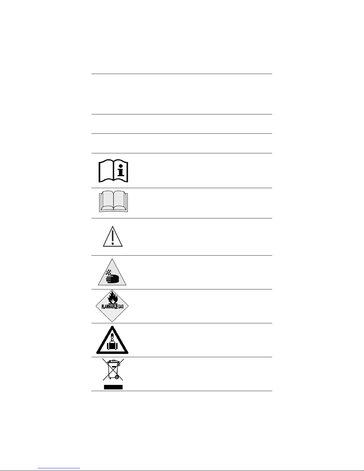
Symbols used in the manual
Open book symbol with an "i"
Indicates the need to consult the instruction manual
Open book symbol
Used to tell the operator to read the manual before using the
machine
Warning symbol
Carefully read the sections marked with this symbol and observe
the indications, for the safety of the operator and the machine
Warning symbol
Indicates danger of gas exhalation and leakage of corrosive
liquids
Warning symbol
Indicates the danger of fire
Do not go near with free flames
Warning symbol
Indicates that the packed product should be handled with
suitable lifting means that comply with the legal requirements
Disposal symbol
Carefully read the sections marked with this symbol, for machine
disposal
Page 3

3
CONTENTS
ON CONSIGNMENT OF THE MACHINE............................................................................................................................................................ 5
INTRODUCTORY COMMENT ............................................................................................................................................................................ 5
INTENDED USE .................................................................................................................................................................................................. 5
SERIAL NUMBER PLATE .................................................................................................................................................................................. 5
TECHNICAL DESCRIPTION............................................................................................................................................................................... 6
SYMBOLS USED ON THE MACHINE ................................................................................................................................................................ 7
GENERAL SAFETY REGULATIONS ................................................................................................................................................................. 9
MACHINE PREPARATION ............................................................................................................................................................................... 10
1. HANDLING THE PACKAGED MACHINE .......................................................................................................................................................................... 10
2. HOW TO UNPACK THE MACHINE ................................................................................................................................................................................... 10
3. HOW TO MOVE THE MACHINE ....................................................................................................................................................................................... 10
4. INSTRUMENT PANEL COMPONENTS (INNOVA 2011 60 B VERSIONS) ...................................................................................................................... 10
5. INSTRUMENT PANEL COMPONENTS (INNOVA 2011 65 -75-85 B INNOVA 2011 70 S) .............................................................................................. 11
6. INSTRUMENT PANEL COMPONENTS (INNOVA 2011 60 B VERSIONS) ...................................................................................................................... 11
7. INSTRUMENT PANEL COMPONENTS (INNOVA 2011 65 -75-85 B INNOVA 2011 70 S) .............................................................................................. 11
8. FOOTBOARD FRONT-RIGHT COMPONENTS ................................................................................................................................................................ 11
9. FOOTBOARD FRONT-LEFT COMPONENTS .................................................................................................................................................................. 12
10. FOOTBOARD REAR COMPONENTS ............................................................................................................................................................................. 12
11. MACHINE'S SIDE COMPONENTS .................................................................................................................................................................................. 12
12. MACHINE'S REAR COMPONENTS ................................................................................................................................................................................ 13
13. TYPE OF BATTERY ......................................................................................................................................................................................................... 13
14. BATTERY MAINTENANCE AND DISPOSAL .................................................................................................................................................................. 13
15. FITTING THE BATTERIES INTO THE MACHINE ........................................................................................................................................................... 13
16. BATTERY CONNECTION AND BATTERY CONNECTORS ........................................................................................................................................... 14
17. BATTERY CHARGER CONNECTION (VERSIONS WITHOUT CB) ............................................................................................................................... 14
18. BATTERY CHARGER CONNECTION (VERSIONS WITH CB) ...................................................................................................................................... 15
19. BATTERY CHARGE LEVEL INDICATOR ....................................................................................................................................................................... 17
20. WORKING FORWARD SPEED ....................................................................................................................................................................................... 17
21. REVERSE FUNCTION ..................................................................................................................................................................................................... 17
22. RECOVERY TANK ........................................................................................................................................................................................................... 17
23. SOLUTION TANK (INNOVA 2011 60-65-75-85 B) .......................................................................................................................................................... 17
24. SOLUTION TANK (70S VERSIONS) ............................................................................................................................................................................... 18
25. FILLING THE SOLUTION TANK ...................................................................................................................................................................................... 18
26. DETERGENT SOLUTION ( VERSIONS WITHOUT CDS ) ............................................................................................................................................. 18
27. DETERGENT SOLUTION (VERSIONS WITH CDS) ....................................................................................................................................................... 19
28. DETERGENT ADJUSTMENT (VERSIONS WITHOUT CDS) ......................................................................................................................................... 20
29. REGULATING THE DETERGENT (VERSIONS WITH CDS) .......................................................................................................................................... 20
30. DETERGENT PUMP PRIMING (VERSIONS WITH CDS)............................................................................................................................................... 21
31. SQUEEGEE ASSEMBLY (INNOVA 2011 60 B VERSIONS) ......................................................................................................................................... 22
32. SQUEEGEE ASSEMBLY (INNOVA 2011 65 -75-85 B INNOVA 2011 70 S) ................................................................................................................. 22
33. SQUEEGEE INCLINATION .............................................................................................................................................................................................. 22
34. ADJUSTING THE SQUEEGEE SUPPORT HEIGHT ....................................................................................................................................................... 22
35. BRUSH ASSEMBLY (INNOVA 2011 60 B VERSIONS) ................................................................................................................................................. 22
36. BRUSH HEAD CASING ASSEMBLY (INNOVA 2011 65-75-85 B VERSIONS) ............................................................................................................. 23
37. DISC BRUSH ASSEMBLY (INNOVA 2011 65-75-85 B VERSIONS) ............................................................................................................................. 23
38. CYLINDRICAL BRUSH ASSEMBLY (INNOVA 2011 70 S) ............................................................................................................................................ 24
39. BRUSH HEAD EXTRA-PRESSURE (INNOVA 2011 65-75-85 B VERSIONS) ............................................................................................................... 24
40. SERVICE BRAKE AND PARKING BRAKE ..................................................................................................................................................................... 25
41. FLASHING LIGHT (OPTIONAL) ...................................................................................................................................................................................... 25
42. EMPTY SOLUTION TANK DEVICE ................................................................................................................................................................................. 25
43. KIT WATER MANAGEMENT (INNOVA 2011 60 B VERSIONS) ..................................................................................................................................... 25
WORK ............................................................................................................................................................................................................... 26
44. PREPARING TO WORK .................................................................................................................................................................................................. 26
45. OVERFLOW DEVICE (INNOVA2011 60 B) ..................................................................................................................................................................... 27
Page 4

4
46. OVERFLOW DEVICE (INNOVA2011 65-75-85 B INNOVA2011 70 S) ........................................................................................................................... 27
AT THE END OF THE WORK ........................................................................................................................................................................... 28
DAILY MAINTENANCE .................................................................................................................................................................................... 29
47. CLEANING THE RECOVERY TANK ............................................................................................................................................................................... 29
48. CLEANING THE SUCTION MOTOR FILTER .................................................................................................................................................................. 29
49. CLEANING THE SQUEEGEE .......................................................................................................................................................................................... 30
50. CLEANING THE SOLUTION TANK AND FILTER ........................................................................................................................................................... 30
51. CLEANING THE FILTER AND SOLUTION TANK (S VERSION) .................................................................................................................................... 31
52. DISC BRUSH ASSEMBLY (INNOVA 2011 60 B VERSIONS) ........................................................................................................................................ 31
53. DISC BRUSH DISASSEMBLY (INNOVA 2011 65-75-85 B VERSIONS) ....................................................................................................................... 31
54. DISASSEMBLY OF CYLINDRICAL BRUSHES (S VERSIONS) ..................................................................................................................................... 32
55. CLEANING DEBRIS HOPPER (S VERSIONS) ............................................................................................................................................................... 32
WEEKLY MAINTENANCE ................................................................................................................................................................................ 34
56. CLEANING OF THE SUCTION HOSE (INNOVA 2011 60 B VERSIONS) ...................................................................................................................... 34
57. CLEANING OF THE SUCTION HOSE (INNOVA 2011 65-75-85 B VERSIONS)............................................................................................................ 34
58. CLEANING OF THE SUCTION HOSE (S VERSIONS) ................................................................................................................................................... 35
59. CLEANING OF THE DETERGENT CANISTER (VERSIONS WITH CDS) .................................................................................................................... 35
EXTRAORDINARY MAINTENANCE ................................................................................................................................................................ 36
60. REPLACING THE FRONT SQUEEGEE RUBBER .......................................................................................................................................................... 36
61. REPLACING THE REAR SQUEEGEE RUBBER ............................................................................................................................................................ 36
62. REPLACEMENT OF THE BRUSH HEAD CASING ......................................................................................................................................................... 36
63. CLEANING OF THE DOSING SYSTEM (VERSIONS WITH CDS) ................................................................................................................................. 36
TROUBLESHOOTING ...................................................................................................................................................................................... 38
64. INSUFFICIENT WATER ON THE BRUSHES .................................................................................................................................................................. 38
65. THE SQUEEGEE DOES NOT DRY PERFECTLY .......................................................................................................................................................... 38
66. THE MACHINE DOES NOT CLEAN WELL ..................................................................................................................................................................... 38
67. EXCESSIVE FOAM PRODUCTION ................................................................................................................................................................................ 38
68. THE SUCTION DOES NOT FUNCTION .......................................................................................................................................................................... 39
69. THE BRUSHES MOTOR DOES NOT FUNCTION (INNOVA 2011 60 B VERSIONS) ................................................................................................... 39
70. THE BRUSHES MOTOR DOES NOT FUNCTION (INNOVA 2011 65 -75-85 B VERSIONS) ....................................................................................... 39
71. IT IS IMPOSSIBLE TO RAISE OR LOWER THE BRUSH HEAD OR SQUEEGEE ........................................................................................................ 39
72. THE MACHINE DOES NOT START ................................................................................................................................................................................ 39
73. ELECTRIC FUSES AND THERMAL CUT-OUTS ............................................................................................................................................................ 39
74. THE AUTOMATIC WATER/DETERGENT DOSING SYSTEM DOES NOT WORK........................................................................................................ 40
DISPOSAL ........................................................................................................................................................................................................ 41
CHOOSING AND USING THE BRUSHES ....................................................................................................................................................... 42
EC DECLARATION OF CONFORMITY ............................................................................................................................................................ 43
EC DECLARATION OF CONFORMITY ............................................................................................................................................................ 44
Page 5
5
On consignment of the machine
When the machine is consigned to the customer, an immediate check must
be performed to ensure all the material mentioned in the shipping documents
has been received, and also to check the machine has not suffered damage
during transportation. If this is the case, the carrier must ascertain the extent
of the damage at once, informing our customer service office. It is only by
prompt action of this type that the missing material can be obtained, and
compensation for damage successfully claimed.
Introductory comment
INNOVA 2011 is a scrubbing machine that is able to clean a wide variety of
types of flooring and types of dirt by using the mechanical action of two disc
or cylindrical brushes, depending on the model, and the chemical action of a
water-detergent solution. As it advances, it also collects the dirt removed and
the detergent solution not absorbed by the floor.
The machine must be only used for this purpose. Even the best
machines will only work well if used correctly and kept in good working order.
We therefore suggest you read this instruction booklet carefully and read it
again whenever difficulties arise while using the machine If necessary,
remember that our customer assistance service (organised in collaboration
with our dealers) is always available for advice or direct intervention.
Intended use
The scrubbing machine is exclusively designed for the professional cleaning
of surfaces and floors in industrial, commercial and public environments. The
machine is only suitable for use in closed (or at least covered) places.
The machine is not suitable for use in the rain, or under water jets. It is
FORBIDDEN to use the machine for picking up dangerous dusts or
inflammable liquids in places with a pote ntially explosi ve atmosphere. I n
addition, it is not suitable as a means of transport for people or objects.
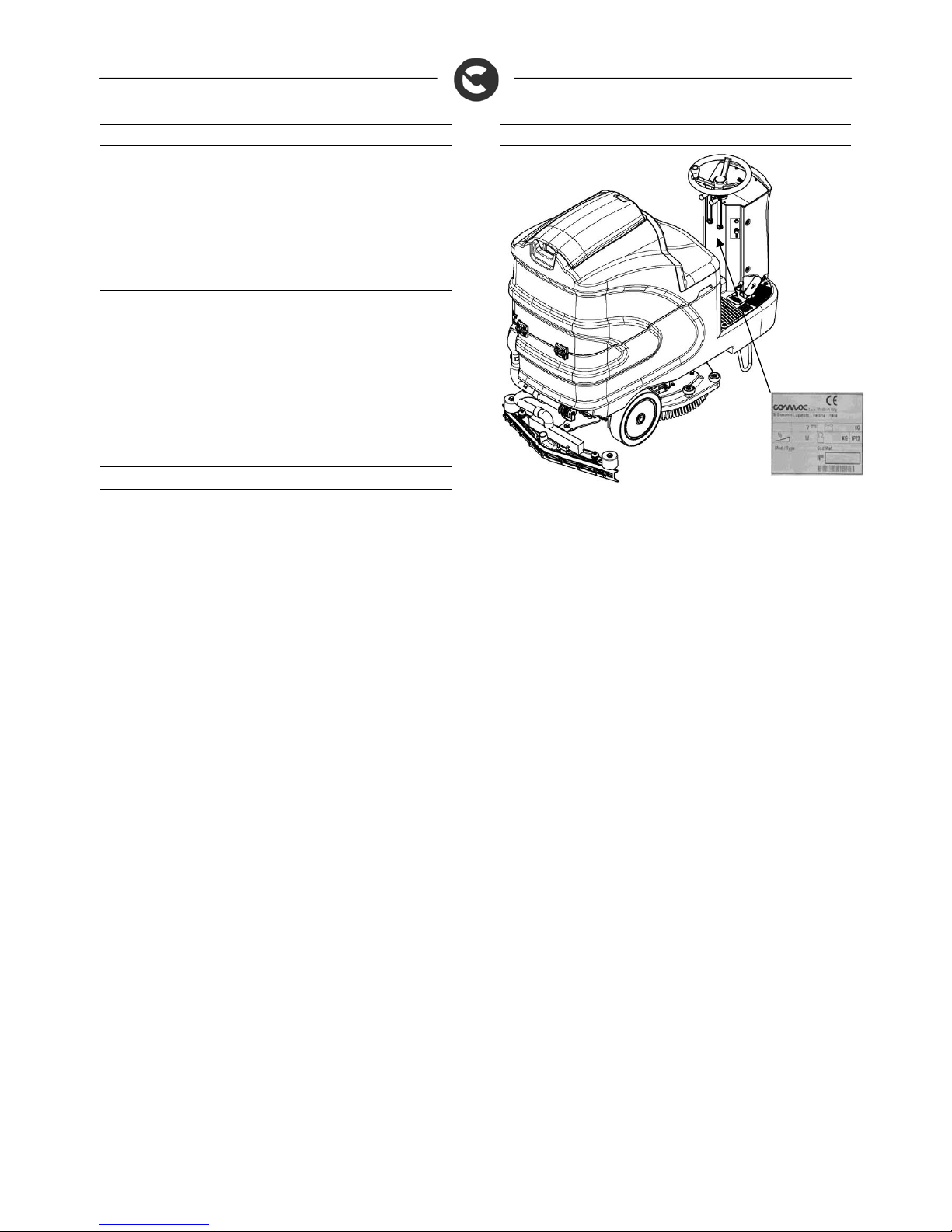
Serial number plate
Page 6

6
TECHNICAL DESCRIPTION U/M 60 B 65 B 75 B 85 B 70 S
Working width mm 610 650 750 850 690
Squeegee width
mm 780 970 970 1085 970
Work capacity, up to m2/h 3660 3900 4500 5100 4100
Disc brush
Nr / mm
1 / 610 2 / 340 2 / 390 2 / 430 -
Cylindrical brushes
Nr / mm
- - - - 1 / 210
Brush rotations giri/min. 170 170 170 170 520
Brush motor V / W 24 / 450 24 / 450 24 / 450 24 / 450 24 / 560
Pressure on the brushes
kg 30 30 – 60 30 – 60 30 – 60 20
Traction motor V / W 24 / 400 24 / 400 24 / 400 24 / 400 24 / 400
Traction wheel
mm
220 220 220 220 220
Forward speed
km/h
06 06 06 06 06
Maximum gradient with full load % 10 10 10 10 10
Suction motor V / W 24 / 310 24 / 310 24 / 310 24 / 310 24 / 310
Suction vacuum mbar 160 160 160 160 160
Rear elastic wheels
mm
300x70 300x70 300x70 300x70 300x70
Solution tank l 110 110 110 110 110
Recovery tank l 125 125 125 125 125
Detergent tank (CDS version only) l
-
5 5 5 5
Steering diameter mm 1910 1910 1910 1910 1910
Machine length mm 1495 1495 1495 1495 1495
Machine height mm 1320 1320 1320
1320
1320
Machine width (without squeegee) mm 680 680 770 855 805
Battery compartment (l x L x h) mm 384x520x340
Rated battery voltage V 24 24 24 24 24
Battery weight (max) kg 136 136 136 136 136
Machine weight (empty and without batteries) kg 223 223 223 223 233
Machine weight in running order (machine + batteries + water + operator) kg 545 544 544 544 554
Noise level (ISO 11201) dB (A) - - - - Hand vibration level (ISO 5349-1) m/s2 - - - - Body vibration level (ISO 2631) m/s2 - - - - -
Page 7
7
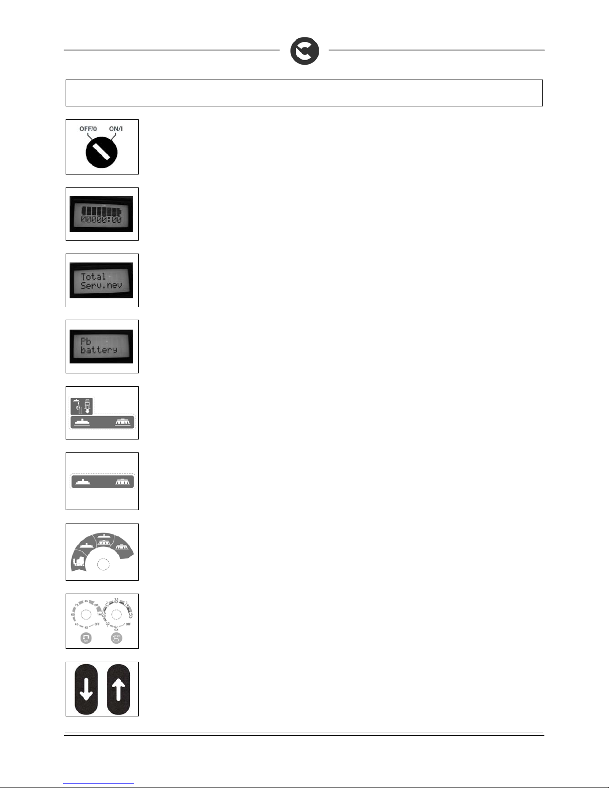
SYMBOLS USED ON THE MACHINE
Main switch symbol (key switch)
Used on the instrument panel, to indicate the key switch for machine operation on (I) or off (O)
Indicator showing battery charge level on the upper line and hour-counter on the lower line
Indicator showing the type of hour-counter (total) on the upper line and the type of service (none) on the lower line
Indicator showing the type of technology of the batteries used (lead)
Brush head / squeegee motion symbol (idle position)
Used to indicate the movement levers of the brush head and squeegee
Brush head / squeegee motion symbol (working position)
Used to indicate the movement levers of the brush head and squeegee
Brush head/squeegee operating symbols
Used to indicate the I-DRIVE programs selector
Symbol denoting regulation of water quantity (l/h) and detergent (%), CDS system
Used on the instrument panel, to indicate the adjustment of the detergent percentage dissolved in the water, and the
amount of water distributed on the brushes
Pedal labels that indicate the forward and reverse direction of the machine
Used to indicate the direction of the machine
Page 8
8
SYMBOLS USED ON THE MACHINE
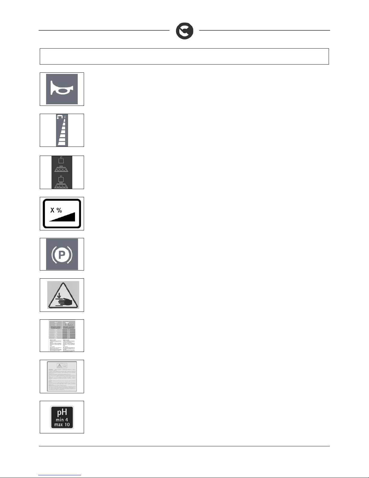
Symbol denoting acoustic alarm
Used to indicate the acoustic alarm button
Water quantity adjustment symbol
Used on the steering column to indicate the knobs for adjusting the quantity of water distributed on the brushes
Symbol denoting pressure applied to the brushes
Used to indicate the pedal to increase the pressure on the brushes
Indicates the maximum gradient
Parking brake symbol
Used on the instrument panel to indicate the red warning light showing parking brake on. Used to indicate the machines
brake lever
Indicates the risk of crushed hands
Label with instructions for the use of standard or concentrated detergents (CDS system only)
Label with warnings on the type of detergent to use (CDS system only)
Label with Ph value of the detergent to use (CDS system only)
Page 9

9
GENERAL SAFETY REGULATIONS
The regulations below must be carefully followed in order to avoid harm to the operator and damage to the machine.
Read the labels on the machine carefully. Do not cover them for any reason and replace them immediately if they become damaged.
The machine must be exclusively used by authorised, trained personnel.
The machine is designed for dry use only and should not be used or kept outdoors in damp conditions.
Disconnect from the mains/battery before performing cleaning or maintenance operations on the machine.
If the machine is used where there is a risk of falling objects, the machine must be equipped with protections against falling objects.
During the working of the machine, pay attention to other people and especially to children.
The machine is not suitable for cleaning carpets.
Do not mix different types of detergent as this may produce harmful gases.
Do not place any liquid containers on the machine.
The storage temperature must be between -25C and +55C; do not store outdoors in damp conditions.
Conditions of use: room temperature between 0°C and 40°C with relative humidity between 30 and 95%
Do not use the machine in an explosive atmosphere.
Do not use the machine as a means of transport.
Do not use acid solutions that could damage the machine and/or harm people.
Do not vacuum inflammable liquids.
Do not use the device to collect dangerous powders.
In the event of a fire, use a powder extinguisher. Do not use water.
Do not knock against shelving or scaffolding, where there is a danger of falling objects. Use protective devices (helmet).
Adapt the speed to the adhesion conditions.
Do not use the machine on surfaces with an inclination greater than the one shown on the plate.
When the machine is in parking mode, remove the key and insert the parking brake.
If you notice any damage to the battery charger cable, contact a COMAC technical assistance centre immediately.
The machine is designed to carry out the washing and dry ing operati ons s imultaneous ly. Differe nt operati ons s hould only be car ried out in ar eas w here
the passage of unauthorised persons is prohibited. Signal the presence of damp floors with suitable signs.
If the machine does not work properly, check this is not caused by failur e to carry out routine maintenance. Otherwise, request the interv ention of the
COMAC technical assistance centre.
If you need to replace any components, request the ORIGINAL spare parts from a COMAC dealer and/or Authorised Retailer.
Use original COMAC brushes only indicated in the paragraph “CHOOSING AND USING THE BRUSHES".
In the event of danger, activate the emergency lever (connector placed under the operator's seat) immediately.
Before carrying out any maintenance work, switch off the machine and disconnect the battery connector.
Restore all electrical connections after any maintenance interventions.
Do not remove any protection devices which require the use of tools in order to be removed.
Do not wash the machine with direct water jets or with pressurised water, nor with corrosive substances.
After at least every 200 hours of operation, have the machine checked by a COMAC assistance centre
To prevent scaling in the solution tank filter, do not fill the tank with detergent solution many hours before using the machine.
Before using the machine, check that all the hatches and covers are positioned as shown in this Use and Maintenance Manual.
Make sure the recovery tank is empty before lifting.
When disposing of consumption materials, observe the laws and regulations in force.
The machine does not cause harmful vibrations.
When your COMAC machine has reached the end of its long work ing life, dispose of the materials it contains (espec ially oils, batteries and e lectronic
components) in an appropriate manner, and bearing in mind that the machine itself was constructed using 100% recyclable materials.
The batteries must be removed from the machine before its disposal.
The batteries must be disposed of in a safe manner, fully observing the laws and regulations in force.
The machine is not suitable for use by children and persons with reduced physical, mental and sensory capabilities, or people who lack experience and knowledge.
Children must be supervised to ensure they do not play with the device.
When the machine if left unattended, engage the parking brake for safety against unintentional movements.
Page 10
10
MACHINE PREPARATION
1. HANDLING THE PACKAGED MACHINE
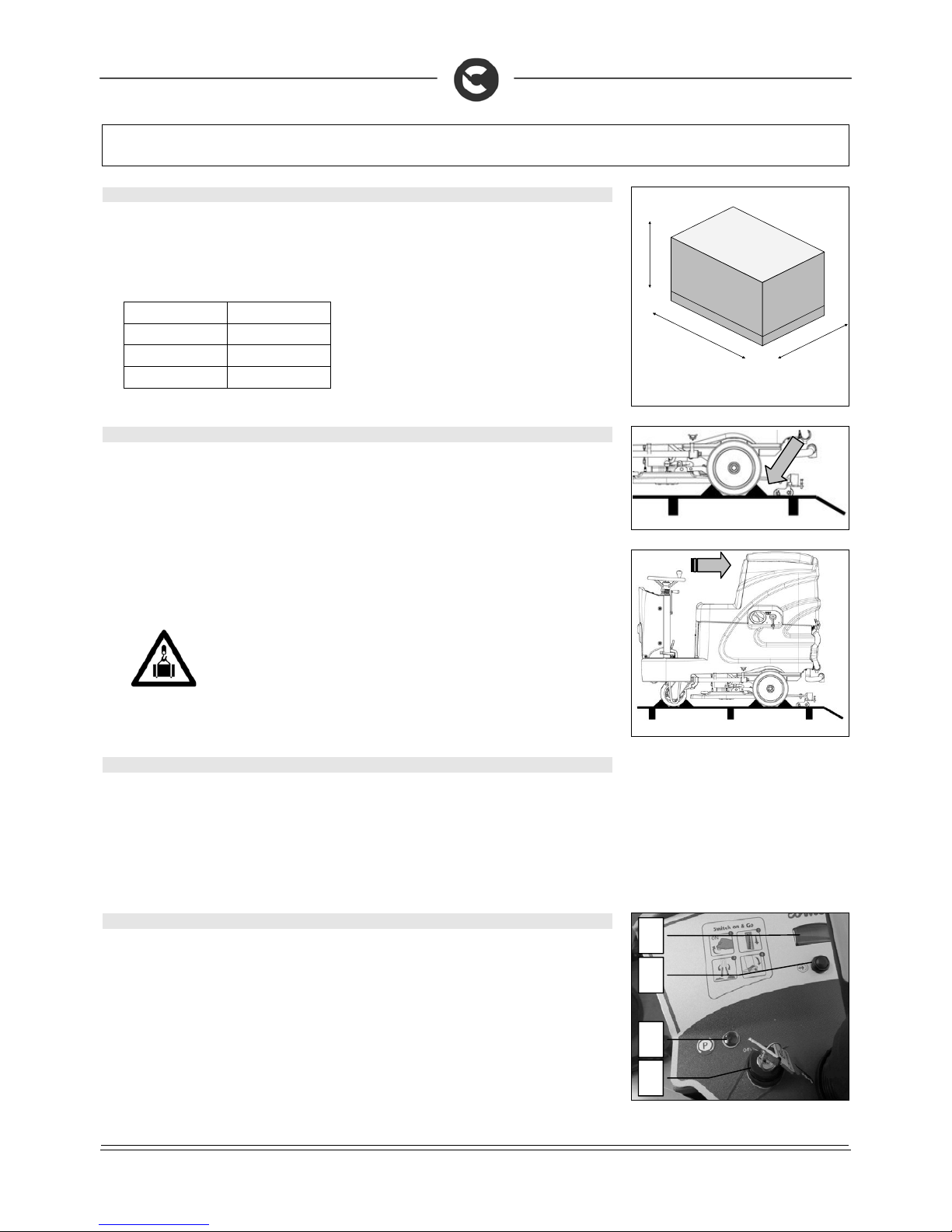
The machine is contained in specific packaging with a pallet for the handling with fork trucks. The
packages cannot be placed on top of each other.
The total mass of the machine with packaging is 240 kg (without batteries).
The dimensions of the packaging is as follows:
60-65-75-85 B 70 S
A: 1610mm A: 1610mm
B: 730mm B: 730mm
C: 1600mm C: 1600mm
A
C
B
2. HOW TO UNPACK THE MACHINE
1. Remove the outer packaging.
2. The machine is fixed to the pallet with wedges which block the wheels.
3. Remove the wedges.
4. Use a chute to get the machine down from the pallet, pushing it backw ards. Do not assemble th e rear
squeegee before unloading the machine, and av oid violently jolting the brush head. To assemble th e
squeegee, read the “ASSEMBLING THE SQUEEGEE” paragraph.
5. Keep the pallet for any future transport needs.
ATTENTION: if the product is delivered in cardboard containers, handle the packed
product with suitable lifting means that comply with the legal requirements.
3. HOW TO MOVE THE MACHINE
1. Make sure the recovery tank and the solution tank are empty
2. Make sure that the detergent can is empty (CDS version)
3. Check that the brush head and squeegee are lifted off the ground
4. Place it on a pallet using a chute
5. Check that the key switch is on OFF and remove the key
6. Engage the parking brake
7. Secure the machine to the pallet using wooden wedges
4. INSTRUMENT PANEL COMPONENTS (INNOVA 2011 60 B VERSIONS)
The instrument panel components are identified as follows:
1. Battery level / hour-counter display
2. Battery level hour-counter display command button
3. Main key switch.
4. Red warning light indicating that the parking brake is on
1
2 4 3
Page 11
11
MACHINE PREPARATION
5. INSTRUMENT PANEL COMPONENTS (INNOVA 2011 65 -75-85 B INNOVA 2011 70 S)
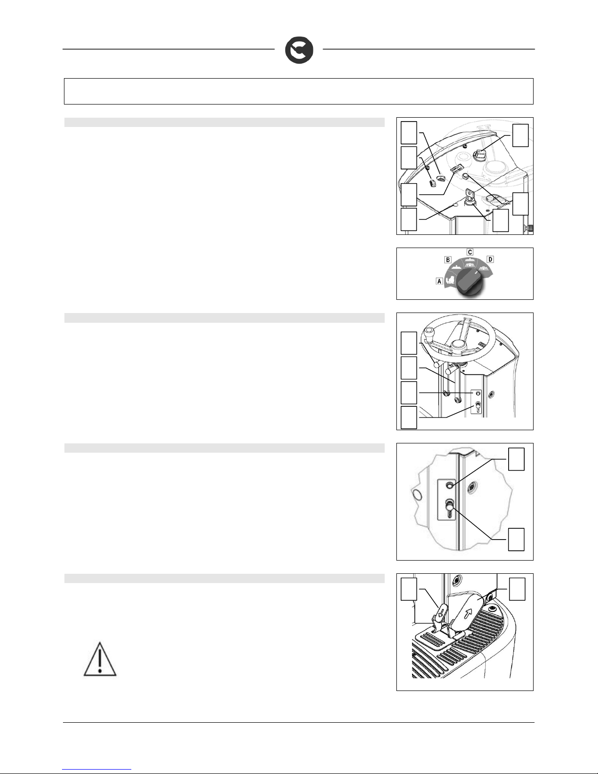
The instrument panel components are identified as follows:
5. Water outlet regulation switch (CDS versions)
6. Detergent outlet regulation switch (CDS versions)
7. Working program adjustment switch, I-Drive device
8. Battery level / hour-counter display
9. Battery level hour-counter display command button
10. Main key switch.
11. Red warning light indicating that the parking brake is on
Choose the desired operating program with the I-Drive device:
A. Transfer: movement of the machine without working
B. Drying: use the squeegee only
C. Washing / Drying: use both the brushes and the squeegee
D. Washing only: use brushes only
6. INSTRUMENT PANEL COMPONENTS (INNOVA 2011 60 B VERSIONS)
The steering column components are identified as follows:
12. Squeegee body lifting lever
13. Brush head body lifting lever
14. Horn button
15. Detergent solution adjustment lever
7. INSTRUMENT PANEL COMPONENTS (INNOVA 2011 65 -75-85 B INNOVA 2011 70 S)
The steering column components are identified as follows:
16. Horn button
17. Detergent solution adjustment lever (version without CDS ) - clean water adjustment lever (v ersion
with CDS)
8. FOOTBOARD FRONT-RIGHT COMPONENTS
The components at the front right of the footboard are identified as follows:
18. Accelerator pedal, forward
19. Accelerator pedal, reverse
WARNING: Only by simultaneously pressing the pedals is the reverse made
15
14
13
12
19 18
16
17
6 5 9 10
8
7
11
Page 12
12
MACHINE PREPARATION
9. FOOTBOARD FRONT-LEFT COMPONENTS
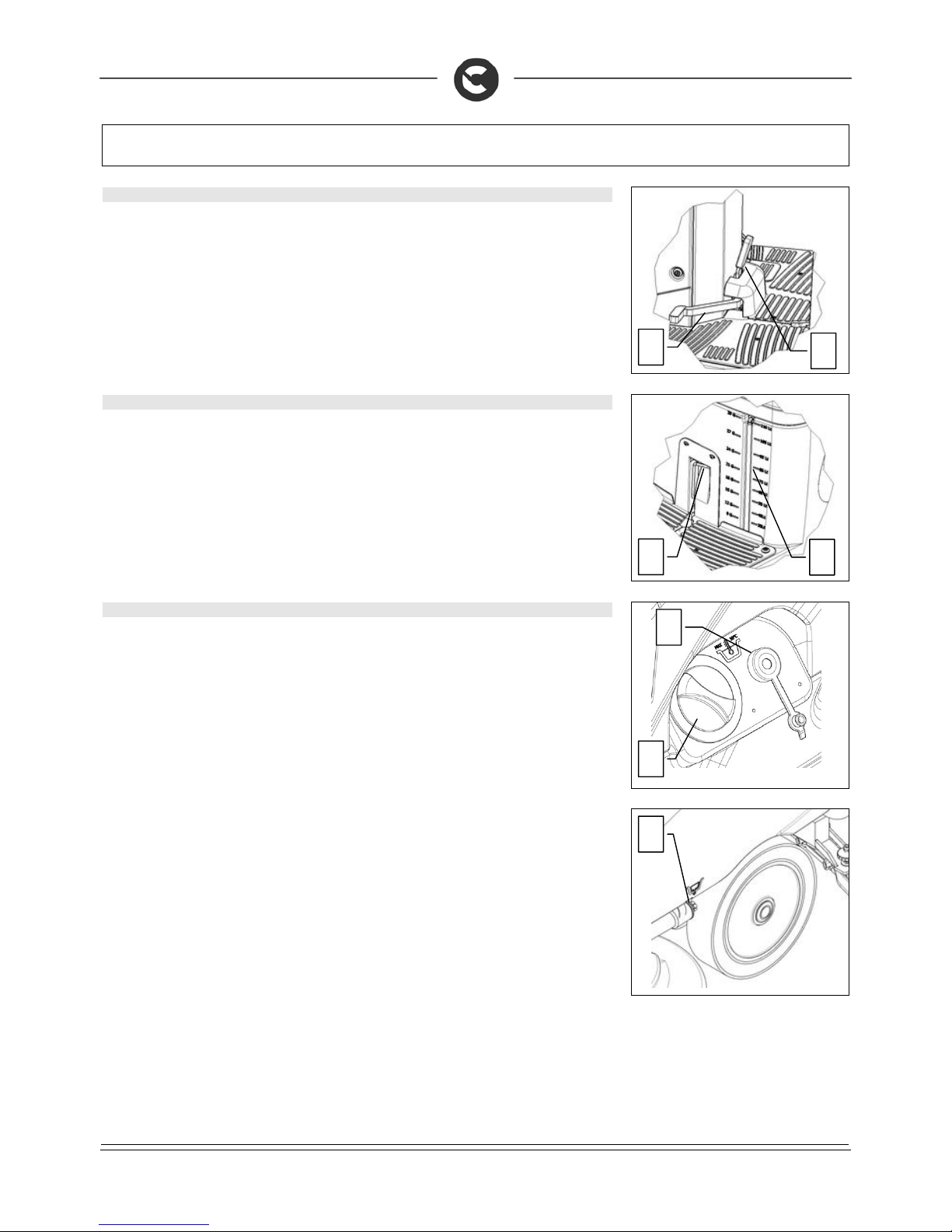
The components at the front right of the footboard are identified as follows:
20. Brake pedal
21. Parking brake lever
10. FOOTBOARD REAR COMPONENTS
The components at the rear of the footboard are identified as follows:
22. The brush head extra-pressure pedal is present on the Innova 2011 65- 75-85 B versions only (see
paragraph BRUSH HEAD EXTRA-PRESSURE)
23. Water level pipe (versions with CDS) or solution level pipe (versions without CDS)
11. MACHINE'S SIDE COMPONENTS
The side components of the machine are identified as follows:
24. Water-detergent filler cap (versions without CDS), water filler (versions with CDS)
25. Water filler cap
26. Water-detergent discharge cap (versions without CDS), water discharge (versions with CDS)
20
21
22
23
26
24
25
Page 13
13
MACHINE PREPARATION
12. MACHINE'S REAR COMPONENTS
The rear components of the machine are identified as follows:
27. Recovery tank discharge cap
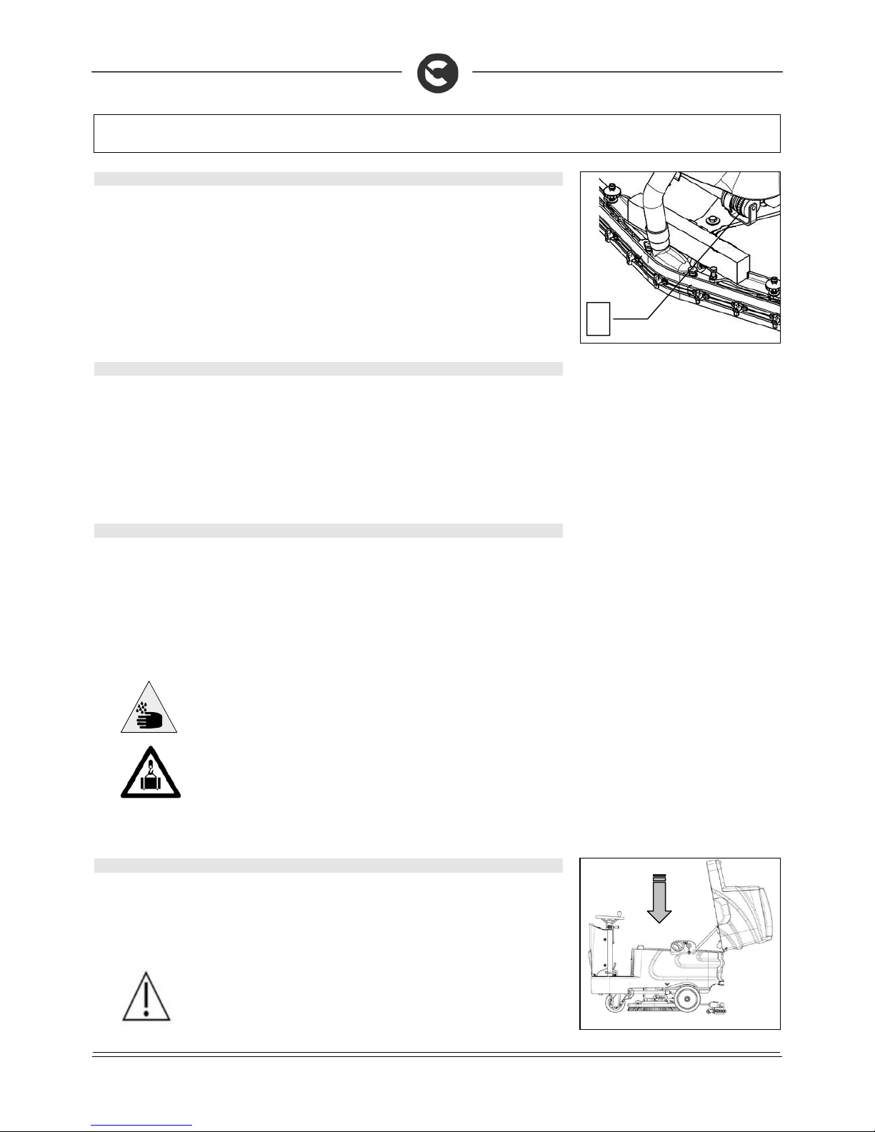
13. TYPE OF BATTERY
To power the machine it is necessary to use:
liquidelectrolyte lead traction batteries;
sealed traction batteries with gasrecombination or gel technology.
OTHER TYPES MUST NOT BE USED.
The batteries must meet the requirements lai d out in the norms: CEI EN 60254-1:2005-12 (CEI 21-5) +
CEI EN 60254-2:2008-06 (CEI 21-7).
The battery compartment can house four 6V or two 12V batteries
For a good operating performance, we suggest the use of four 6V/210 Ah C5 batteries
14. BATTERY MAINTENANCE AND DISPOSAL
For maintenance and recharging, comply with the instructions provided by the battery manufacturer.
Particular attention must be paid when choosing the battery charger, if not supplied, since there are
different kinds according to the type and capacity of the battery.
When the battery reaches the end of its working life, it must be disconn ected by expert, trained p ersonnel,
then lifted (using the grips and suitable lifting devic es) to remove it from the battery comp artment. DEAD
BATTERIES ARE CLASSIFIED AS DANGEROUS WASTE AND MUST BE DELIVERED TO THE
AUTHORISED BODIES FOR CORRECT DISPOSAL.
ATTENTION: you are advised to always wear pr otectiv e g loves , to av oid the r is k
of serious injury to your hands
ATTENTION: You are advised to on ly lift and move the batteries with lifting and
transportation means suitable for the specific weight and size
15. FITTING THE BATTERIES INTO THE MACHINE
The batteries must be housed in the special compa rtment beneath the recovery tank. They should be
handled using lifting equipment that is suitable in terms of both weight and hook-up system. They must
also satisfy the requirements of Standard CEI 2 1-5. T he d ime ns ions o f the battery compartment are: 384 x
520 x H340 mm.
WARNING: For battery maintenance and daily recharging, you must fully respec t
the indications provided by the manufacturer or retailer. All installation and
maintenance operations must be carried out by specialised personnel.
27
Page 14
14
MACHINE PREPARATION
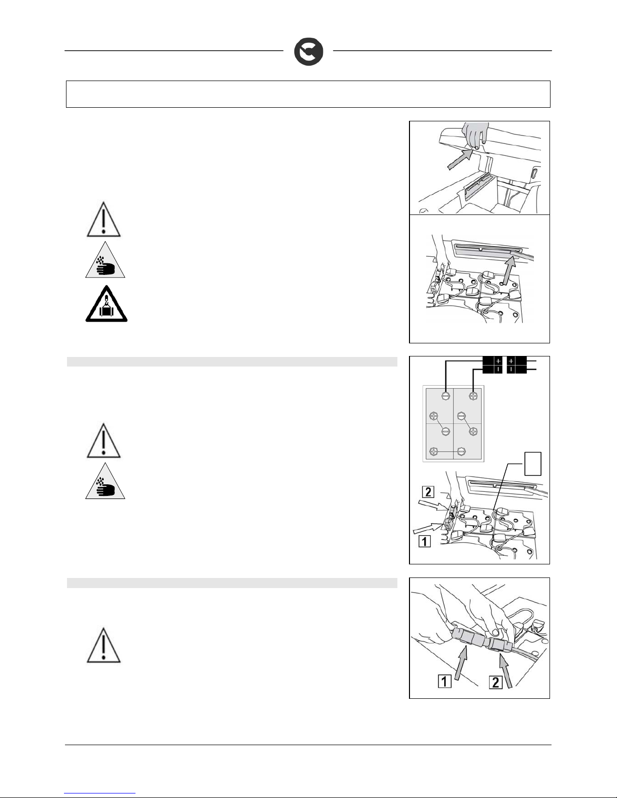
To insert the batteries you must:
1. Lock the machine engaging t he brake lever
2. Make sure that the key switch is in the “OFF” position
3. Make sure the recovery tank is empty, otherwise empty it completely
4. Grip the handle under the seat to open the recovery tank.
5. Lift the recovery tank until it hooks to the end of the safety clamp.
6. house the batteries in the compartment, positioning the poles “+” and “-“ opposite each other
WARNING: you are advised to use airtight batteries only , to avoid the lea kage
of acids!
ATTENTION: you are advised to always wear protect ive gloves, to avoid the
risk of serious injury to your hands
ATTENTION: You are advised to only lift and move the batteries with lifting
and transportation means suitable for the specific weight and size
16. BATTERY CONNECTION AND BATTERY CONNECTORS
1. connect the batteries in series - using the jumper cables supplied (3) - to the poles “+” and “-“
2. Connect the battery connec tor cable (1) to the termi nal poles “+” and “-“ to obtain a vol tage of 24V on
the clamps
3. Connect the battery connector (1) to the machine connector (2).
ATTENTION: you are advised to have the electric c onnections made by a
qualified, COMAC-trained technician
ATTENTION: y ou are advised to always wear protective gloves, to avoid the
risk of serious injury to your hands
17. BATTERY CHARGER CONNECTION (VERSIONS WITHOUT CB)
In order not to cause permanent damage to the batteries it is essential to avoi d their complete dis charge:
arrange the recharge within a few minutes of the switching on of the flashing "discharged batteries" signal.
ATTENTION: never leave the batteries completely discharged, even if the
machine is not being used. Check the battery charger is suitable for the
batteries installed, in terms of both capacity and type.
3
Page 15
15
MACHINE PREPARATION
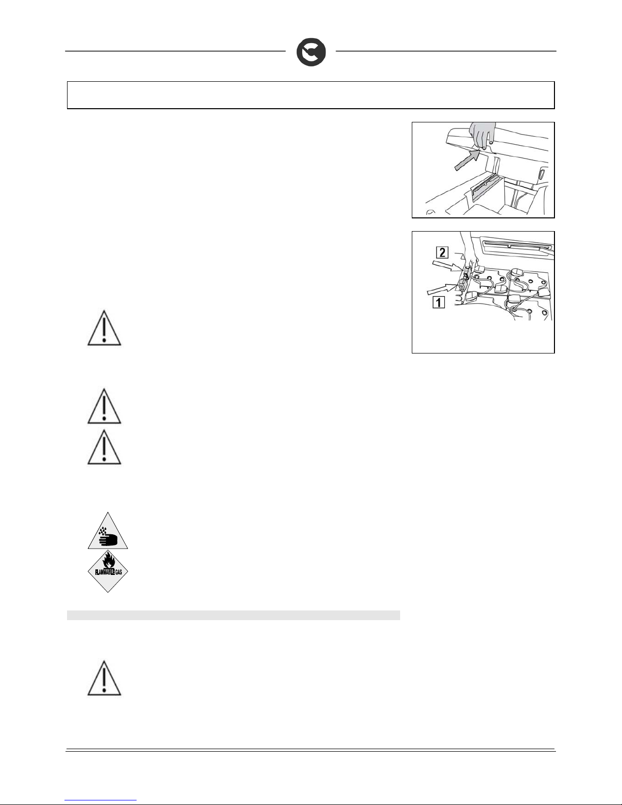
To connect the batteries you must:
1. Make sure the recovery tank is empty, otherwise empty it completely
2. Make sure that the key switch is in the “OFF” position
3. Move the machine near to the battery charger
4. Engage the parking brake
5. Grip the handle under the seat to open the recovery tank.
6. Lift the recovery tank until it hooks to the end of the safety clamp.
7. Disconnect the electrical connector from the battery connector (1) from the machine connector (2)
8. Connect the battery charger cable connector
9. Close the recovery tank until the prop is hooked in the first point of the safety stop
The coupling connector of the battery charger is consigned inside the bag containing this instruction
booklet, and must be assembled on the cables of the battery charger as indicated in the instructions.
ATTENTION: this process must be carried out by qualified personnel. An
incorrect connection of the connector may cause problems with machine
functioning.
10. Connect the recently wired cable to the external battery charger
ATTENTION: Carefully read the use and maintenance instructions of the
battery charger that is used for charging.
ATTENTION: Keep the recovery tank open for the duration of the battery
recharging cycle to allow gas fumes to escape
11. After recharging the batteries completely, the battery connector (1) must be connected to the
machine connector (2).
ATTENTION: danger of exhalation of gas and leakage of corrosive liquids
ATTENTION: danger of fire: do not go near with free flames
18. BATTERY CHARGER CONNECTION (VERSIONS WITH CB)
In order not to cause permanent damage to the batteries it is essential to avoid their c omplete discharge :
arrange the recharge within a few minutes of the switching on of the flashing "discharged batteries" signal.
ATTENTION: never leave the batteries completely discharged, even if the
machine is not being used. Check the battery charger is suitable for the
batteries installed, in terms of both capacity and type.
Page 16
16
MACHINE PREPARATION
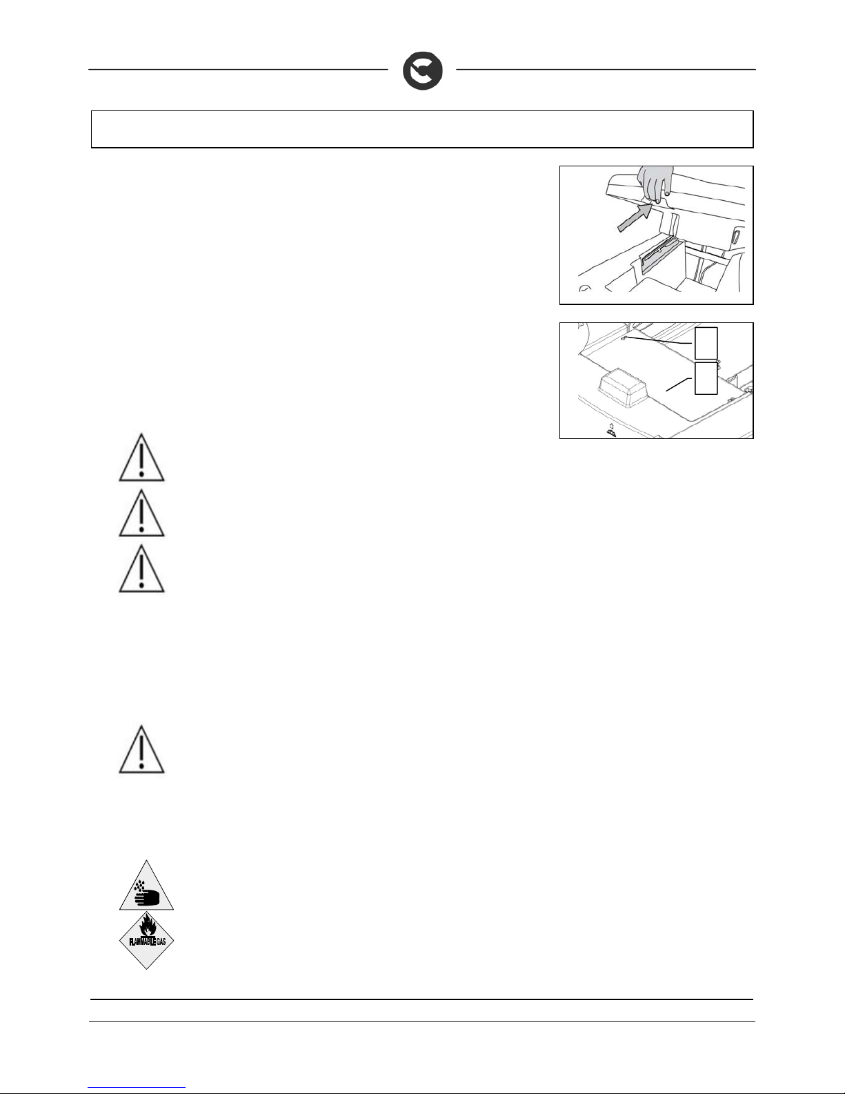
To connect the batteries you must:
1. Make sure the recovery tank is empty, otherwise empty it completely
2. Make sure that the key switch in the “0” position
3. Move the machine near to the battery charger
4. Engage the parking brake
5. Grip the handle under the seat to open the recovery tank.
6. Lift the recovery tank until it hooks to the end of the safety clamp.
7. Remove the protective sheath (1), pull ing it toward the rear of the machine until the screw (2) can
pass through the slot present on the sheath
8. Connect the battery charger cable to the socket on the charger itself
9. Close the recovery tank until the prop is hooked in the first point of the safety stop
10. Plug the battery charger cable into the mains socket
The charger power cable is delivered inside the bag containing this instruction booklet.
ATTENTION: this process must be carried out by qualified personnel. An
incorrect connection of the connector may cause problems with machine
functioning.
WARNING: Carefully read the use and maintenance manual of the charger
that is delivered inside the bag containing this instruction booklet.
WARNING: Before inserting the charger power cable into the s ocket, verify
that there is no condensate or other forms of liquids.
ATTENTION: the machine is equipped with an automatic system that
disconnects the power supply from the electrical system while the batteries are
being recharged
ATTENTION: in order not to cause permanent damage to the batter ies it is
essential to avoid their complete discharge: arrange the recharge wit hin a few
minutes of the switching on of the flashing "discharged batteries" signal
ATTENTION: never leave the batteries completely discharged, even if the
machine is not being used
ATTENTION: for the daily recharging of the batteries, you must fully respect
the indications provided by the manufacturer or retailer. All installation and
maintenance operations must be carried out by specialised personnel
ATTENTION: Always make sure the green LED of the battery charger is on
before using the machine again
ATTENTION: danger of exhalation of gas and leakage of corrosive liquids
ATTENTION: danger of fire: do not go near with free flames
2
1
Page 17
17
MACHINE PREPARATION
19. BATTERY CHARGE LEVEL INDICATOR
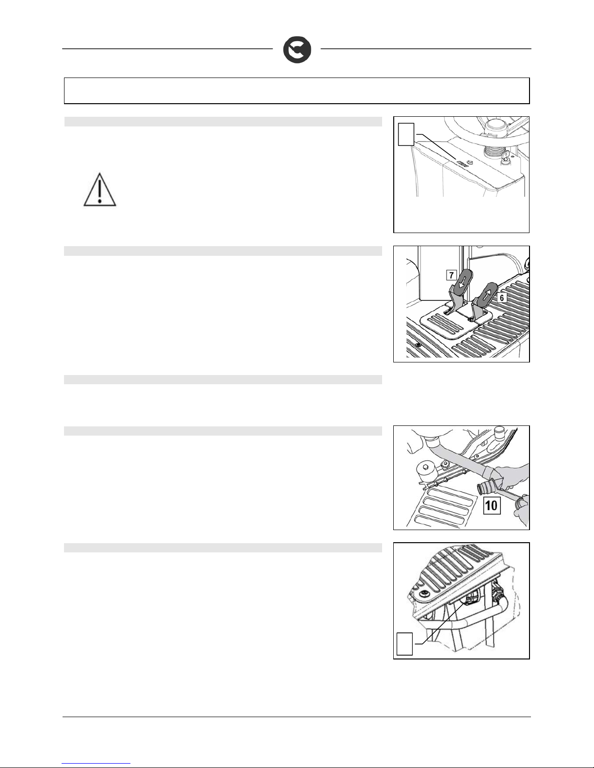
On the instrument panel of the machine there is a monitor (1) indic ating (a mongst oth er thing s) the batt ery
charge status. If the upper line contains 8 light indicator s, the batt ery charge level is 100%. If the ed ges of
the indicators are flashing, this means the batteries are run down.
ATTENTION: a few seconds after the last indicator on the monitor has
flashed, the brush motor will automatically switch off. With the remaining
charge it is possible to complete the drying process before recharging
20. WORKING FORWARD SPEED
This machine is equipped with electronic traction control.
To move the machine, after having turned the key in the ON position, push the drive pedal (6) adjusting
the speed by pressing and releasing the pedal. The machine will then start moving.
21. REVERSE FUNCTION
To make a reversing manoeuvre, press both pedals (6 and 7) the machine will then start moving
backwards. During reverse motion, the machine emits an acoustic signal.
22. RECOVERY TANK
Make sure the recovery tank is empty, otherwise empty it completely.
Check the cap of the drainage tube (10) (on the rear of the machine) is correctly closed.
23. SOLUTION TANK (INNOVA 2011 60-65-75-85 B)
The recovery tank must be completely empty each time the solution tank is filled.
Remove the front inlet cap and check the solution filter is correctly fitted.
Check that the solution filter cap (1), under the solution tank in the front right of the machine, is properly closed.
1
1
Page 18
18
MACHINE PREPARATION
24. SOLUTION TANK (70S VERSIONS)
The recovery tank must be completely empty each time the solution tank is filled.
Remove the front inlet cap and check the solution filter is correctly fitted.
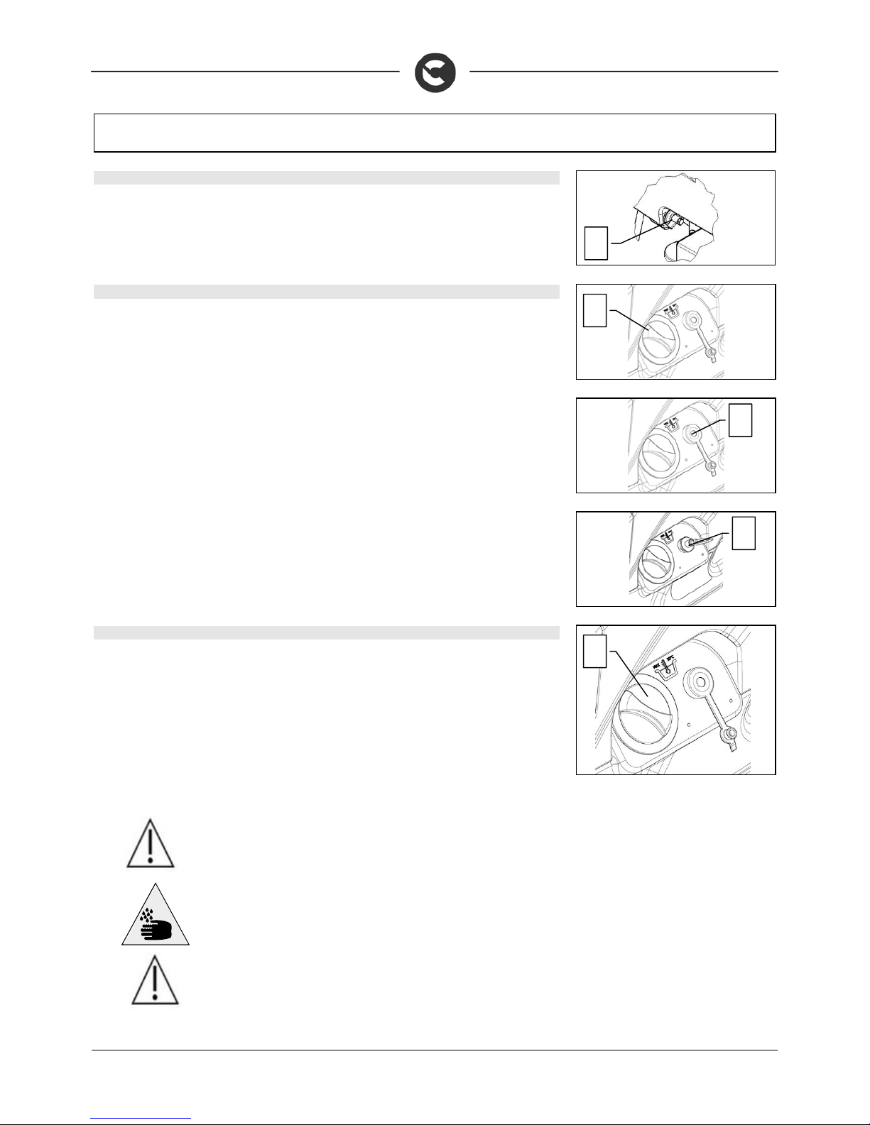
Check that the solution tank discharge ca p (1), under the solution ta nk in the front left of the machine, is
properly closed.
25. FILLING THE SOLUTION TANK
The solution tank can be filled in three different ways:
1. Unscrew the filler cap (1) and fill using a hose.
2. Using the rubber cap (2), this supports the water hose on its own, be sur e to unsc rew the cap to al low
the proper vent of air.
3. Using on request (optional) a tank clean water refillin g system via a quick coupling (3), FFF with float
to control the overflow.
26. DETERGENT SOLUTION ( VERSIONS WITHOUT CDS )
Remove the filler cap and check the solution filter (1) is correctly assembled.
Check that the filter cap, under the solution tank in the front right of the machine, is properly closed.
Fill it with clean water at a temperat ure not exceeding 50C. The amount inside th e tank can be seen by
means of the level pipe on the fr ont left of the seat. The s olution tank has a max imum capacity of about
110 litres. Add the liquid detergent to the tank in the co ncentration and m anner indic ated on the deterg ent
manufacturer's label. The formation of excess foam could damage the suction motor, so use only the
minimum amount of detergent that is necessary.
WARNING: Always use detergents whose manufacturer's label indicates their
suitability for scrubbing machines. Do not use acid or alkaline products or
solvents without this indication.
ATTENTION: Protective gloves should always be worn before handling
detergents or acidic or alkaline solutions to avoid serious injury to hands.
ATTENTION: always use low foam detergent. To avoid the production of
foam, before starting to clean, put a minimum quantity of antifoam liquid into
the recovery tank. Do not use pure acids.
2
1
1
3
1
Page 19
19
MACHINE PREPARATION
27. DETERGENT SOLUTION (VERSIONS WITH CDS)
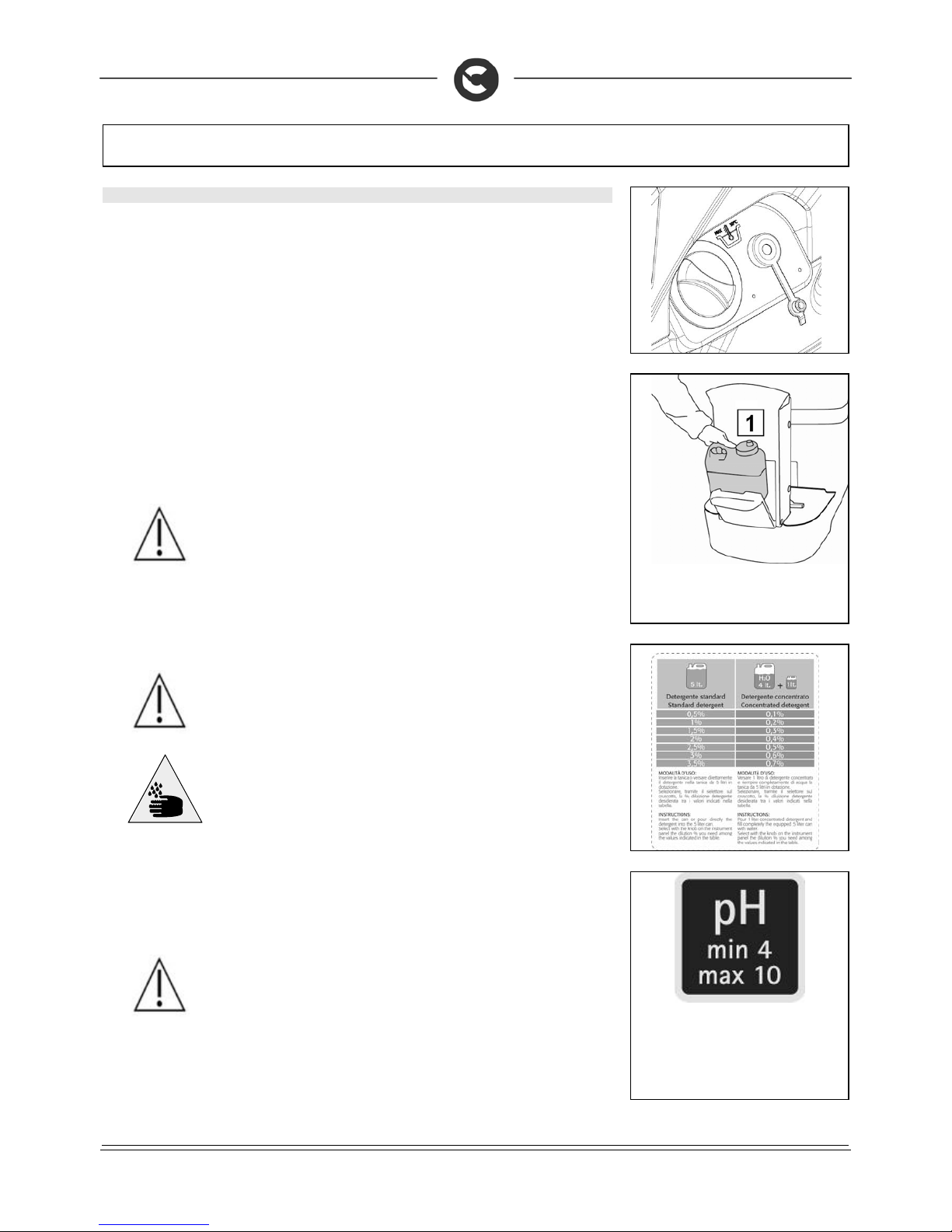
Remove the filler cap and check the solution filter (1) is correctly assembled.
Check that the filter cap, under the solution tank in the front right of the machine, is properly closed
Fill it with clean water at a temperat ure not exceeding 50C. The amount inside th e tank can be seen by
means of the level pipe on the fr ont left of the seat. The s olution tank has a max imum capacity of about
110 litres.
Insert the detergent as follows:
1. Check the switch key is on “OFF”.
2. Open the detergent canister compartment (1) located in front of the steering column
3. Unscrew the cap of the canister in the c ompartment and fill it with liquid detergent in the manner
indicated on the label supplied with the machine. Make sure to properly close the screw cap to
prevent leakage during operation, and that the detergent s uction filter is properly positioned on the
bottom of the canister
4. Close the detergent canister compartment
ATTENTION: always use low foam detergent. To avoid the production of
foam, before starting to clean, put a minimum quantity of antifoam liquid into
the recovery tank. Do not use pure acids.
5. To regulate the water/detergent mixture, careful ly read the “REGULATING THE DETERGENT WITH
THE CDS SYSTEM” paragraph.
ATTENTION: always use detergents whose manufacturer's label indicates
their suitability for scrubbing machines. Do not use acid or alkaline products or
solvents without this indication.
In addition, you are advised to always use low foam detergents.
Do not use pure acids or detergents with a stronger gradation than that
indicated on the label supplied.
ATTENTION: Protective gloves should always be worn before handling
detergents or acidic or alkaline solutions to avoid serious injury to hands.
WARNING: The dosing system is suitable for frequent maintenance cleaning.
Acid or alkaline maintenance detergent tank be us ed with pH values between
4 and 10 and that do not contain: oxidising agents, chlorine or bromine,
formaldehyde, mineral solvents.
The detergents used must be suitable for use with scrubbing machines.
Wash the circuit with water after use if the system is not used daily. The
system can be excluded. In case of sporadic use of detergents with pH
between 1-3 or 11-14, use the scrubbing machine in the traditional way by
adding the detergent in the clean water tank and excluding the dosing circuit.
Page 20
20
MACHINE PREPARATION
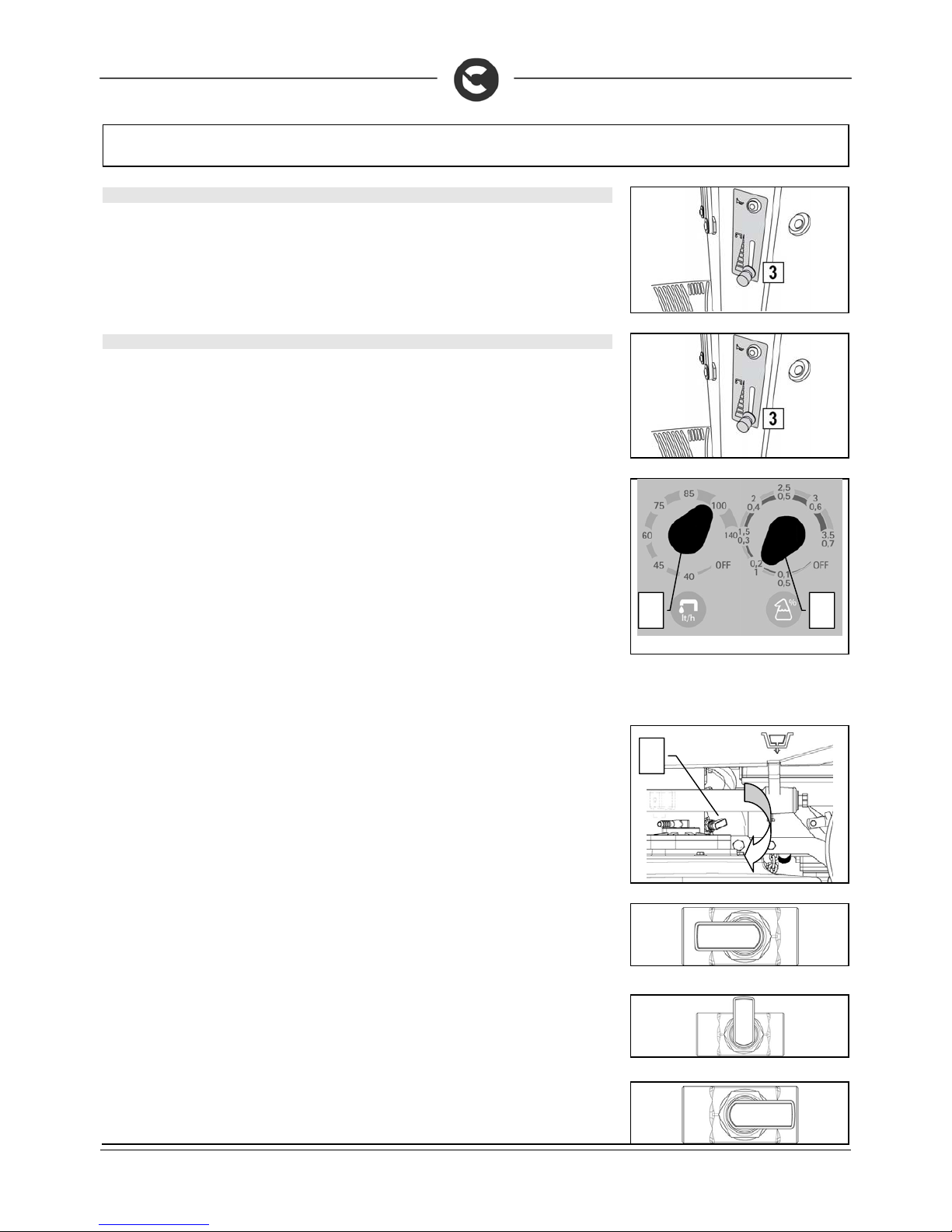
28. DETERGENT ADJUSTMENT (VERSIONS WITHOUT CDS)
Firstly, fully open the outflow of the tap, by means of the lever (3) on the s teering column. During the first
few meters, check that the amount of solution to wet the floor is s uffic ient, but no t too muc h that it exits the
splash-guard, the adjustment of the detergent application is made by means of lever (3) (shifting it
downwards increases the flow, shifting it upwards dec reases it). Bear in mind that the correc t amount of
solution is always depends on the nature of the floor, the degree of dirt and the forward speed.
29. REGULATING THE DETERGENT (VERSIONS WITH CDS)
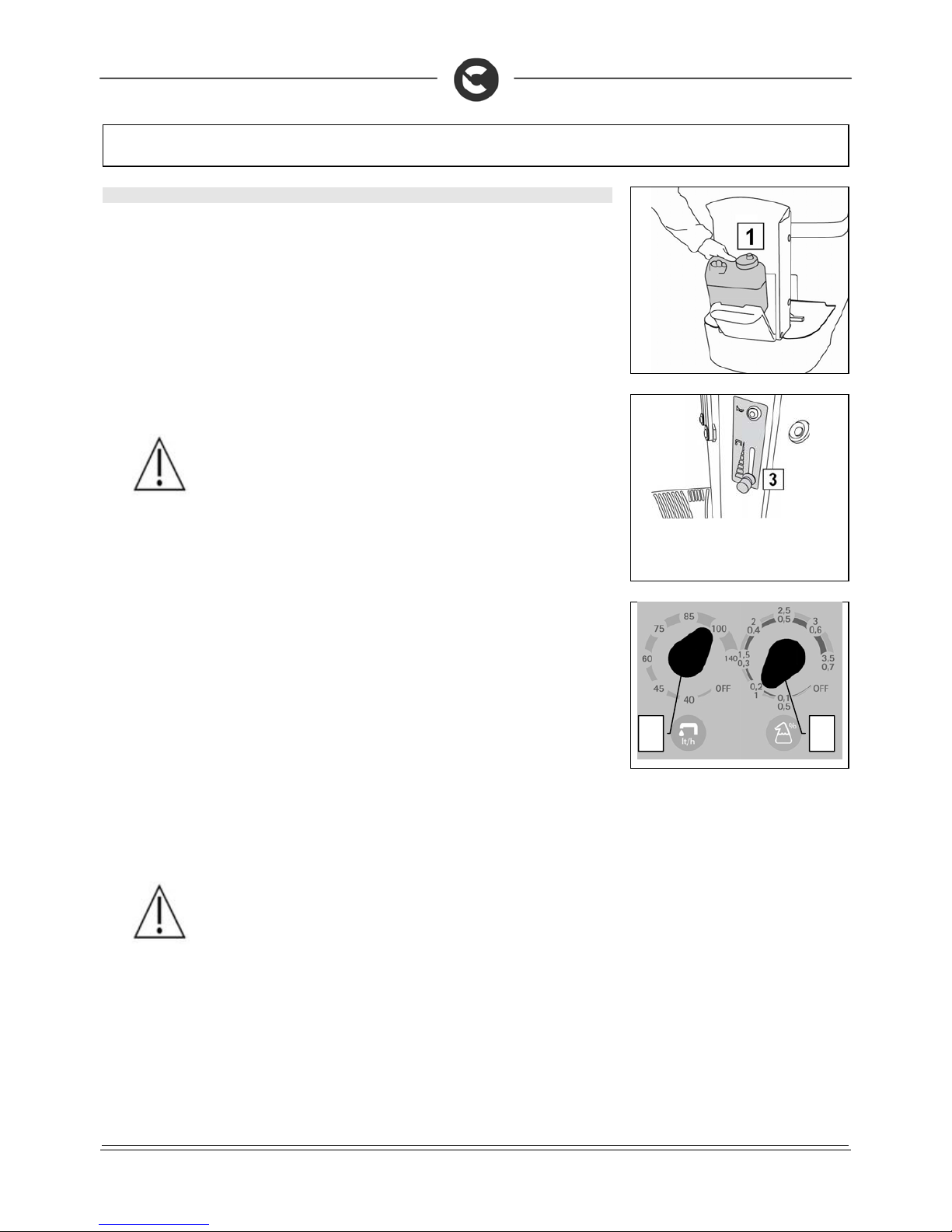
Firstly, fully open the outflow of the tap, by means of the lever (3) on the steering colu mn. Position the
water flow adjustment knob (1) on zero. Position the detergent adjus tment knob (2) on zero. By pressing
the accelerator pedal the brushes start, the machine begins to move and the detergent is distributed.
During the first few meters:
1. Regulate the flow of detergent solution to the brus hes by rotati ng the k no b (1) clock wise. The q uantit y
of solution varies from a minimum of 30 litres/hour to a maximum of 75 litres/hour, with 7 set
measurement points. The right solution fl ow should be proportional to the degree of dir t on the floor.
In addition, remember that the time available for continuous work ing depends on the quanti ty of water
in the tank: for example, work autonomy with a full tank (about 85 litres ) and the selector ( 1) on 30 is
about 3 hours.
2. Regulate the percentage of detergent in the s olution by rotating the knob (2) clockwise. The lower
value is equal to 0.5% (for standard detergents ) or 0.1% (for a concentrated detergent, diluted as
indicated on the label supplied with the machin e), while the higher value is equal to 3.5% or 0.7%,
with 7 set points. Use high detergent percentages to remove very greasy dirt from the floor.
When you have finished regulating the quantities , you can remov e the k nobs and cov er the hol es with t he
rubber caps supplied.
WARNING: If the CDS system does not work, or you want to clean w ithout using this device, you can
intervene on the tap (3) on the brush head near the solenoid valve, rot ati n g th e lev er by 180° as shown in
the figure. Rotate the knobs (1) and (2) anticlockwise, to “OFF”.
ATTENTION: before regulating the solution, check there is deterge nt in the inner can, and that the side
water tap is turned on.
To avoid any tampering with the set regulation, you can remove the two switc hes and c over the two ho les
with the plastic caps supplied with the machine.
To resolve any malfunctioning of the CDS system, contact the COMAC assistance centre.
WARNING: By positioning the tap lever in this way the CDS dosing system is excluded and the detergent
solution is deposited on the brushes. Rotate the knobs (2) and (3) anticlockwise, to the “0” position.
WARNING: By positioning the tap lever in this way, the detergent solution is not distributed on the
brushes. Rotate the knobs (2) and (3) anticlockwise, to the “0” position.
WARNING: By positioning the tap lever in this way the CDS dosing system is activated.
1 2
3
Page 21
21
MACHINE PREPARATION
30. DETERGENT PUMP PRIMING (VERSIONS WITH CDS)
Before starting work the detergent pump must be primed, to do so proceed as follows:
1. Check that the main switch is in the “Off – 0” position
2. Check that the battery connector is disconnected from the machine connector
3. Check the parking brake is correctly engaged
4. Make sure the recovery tank is empty, otherwise empty it
5. Open the detergent canister compartment (1) located in front of the steering column
6. Unscrew the detergent tank cap and fill the tank with the desired product
ATTENTION: always use low foam detergent. To avoid the production of
foam, before starting to clean, put a minimum quan tity of antifoam liquid into
the recovery tank. Do not use pure acids.
7. Close the lid of the detergent tank, taking care that the suction filter is positioned at the bottom of the
tank. Reposition it in the tank compartment
8. Check there is clean water in the solution tank
9. Check that the water tap is turned on fully (3)
10. Check that the by-pass tap is in the “dosing system” position
11. Turn the water flow rate adjustment knob (1) to the maximum position
12. Turn the detergent percentage adjustment knob (2) to the maximum position
13. Insert the battery connector into the machine connector.
14. Place the main switch in position “ON – I”
15. Disengage the parking brake
16. Select the "Wash only" program with the I-Drive device
17. Press the forward movement pedal to activate the brush head and the dosi ng system
18. Wait a few moments with the dead man's lever pressed (normally 20 to 40 seconds) to allow the
insertion of the system
19. Proceed with the desired adjustment for normal cleaning
WARNING: The machine will deliver solution during this operation
1
2
Page 22
22
MACHINE PREPARATION
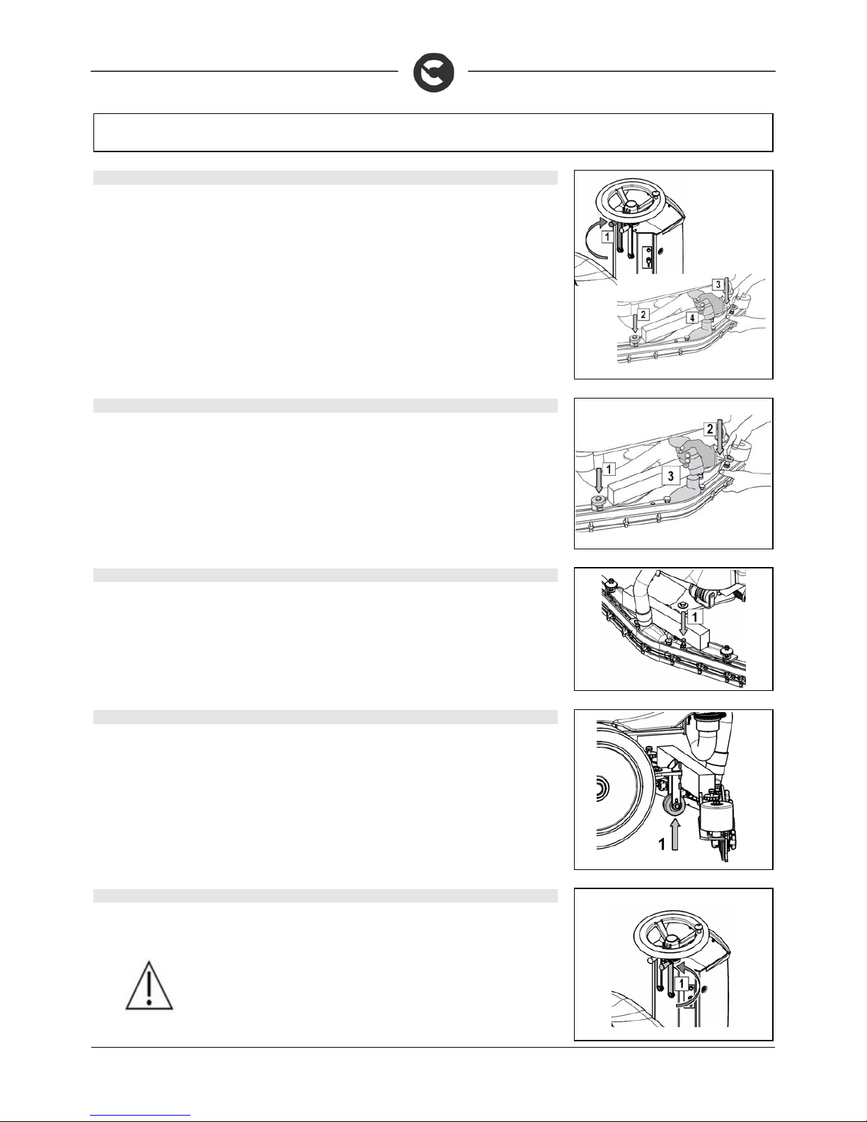
31. SQUEEGEE ASSEMBLY (INNOVA 2011 60 B VERSIONS)
For packaging reasons, the squeegee is supplied disassembled from the machine, and must be
assembled as shown in the figure.
Raise the squeegee connector by means of the lefthand lever (1), turning it clockwise until in the vertical position.
Make sure the parking brake is engaged and that the main s witch is OFF. First thread left pin (2) of the
squeegee into the left slot on the arm and then right pin (3) into the right s lot, being careful to keep the
spring and the washer above the arm’s flat bar. Th is c an be simpl ified by first lo oseni ng th e handw heel on
the pin. Then re-tighten the handwheel to block the squeegee in place.
Insert the squeegee tube in the appropriate sleeve (4).
32. SQUEEGEE ASSEMBLY (INNOVA 2011 65 -75-85 B INNOVA 2011 70 S)
For packaging reasons, the squeegee is supplied disassembled from the machine, and must be assembled
as shown in the figure. Make sure the parking brake is engaged and that the main switch is OFF. Make sure
that the squeegee support is ra i sed, th e sele cted working p rogra m i s t he t ran sport at ion p rogram .
First threading left pin (1) of the squeeg ee into the left slot on the ar m and then right pin ( 2) into the righ t
slot, being careful to keep the spring and the washer above the arm’s flat bar. This can be simplified by
first loosening the handwheel on the pin. Then re-tighten the handwheel to block the squeegee in place.
Insert the squeegee tube in the appropriate sleeve (3).
33. SQUEEGEE INCLINATION
During working operation, the rear rubber is slight ly tilted backwards (by about 5mm) in a uniform way for
its whole length.
If it is necessary to increase the bend of the rubber in the central part, you must tilt the squeegee
backwards, rotating the adjuster screw (1) clockwise.
34. ADJUSTING THE SQUEEGEE SUPPORT HEIGHT
The height of the squeegee must be adjusted on the basis of the state of wear and tear of the rubber.
Carry out the following operations for adjustment:
1. unscrew the locking nut
2. raise or lower the wheel (1) by sliding it on the slot of the support
3. block it by tightening the locking nut once the required height is reached.
Note: To facilitate the operation, completely lower the squeege e and put a spacer of a few millimetres ( 2
to 4 mm depending on the type of rubber) under the wheel.
35. BRUSH ASSEMBLY (INNOVA 2011 60 B VERSIONS)
1. Make sure the parking brake is engaged and that the main switch is OFF
2. Raise the brush head by turning the righthand lever (1 ) for the counter-clockw ise movement of the
brush head.
WARNING: during this operation, verify that there are no people or objects
near the brush.
Page 23
23
MACHINE PREPARATION
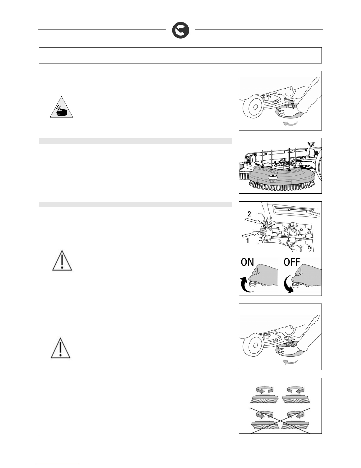
3. With the brush head up, insert the brushes in the plate housing be neath the brush head, turning
them until the three pins enter the niches in the plate itself; turn the brus h clockwise until t he pin is
pushed towards the coupling spring and is locked into place.
ATTENTION: you are advised to always wear protective gloves, to av oid the
risk of serious injury to your hands
36. BRUSH HEAD CASING ASSEMBLY (INNOVA 2011 65-75-85 B VERSIONS)
The casing of the brushing base that for reasons of packaging are supplied disassembled from the
machine, must be mounted as shown. Make sure the parking brake is engaged and that the main switch is
OFF. Unscrew the 8 screws on the brush head (4 per side). Position the two c asings (right and left) and
secure them with the previously removed screws.
37. DISC BRUSH ASSEMBLY (INNOVA 2011 65-75-85 B VERSIONS)
1. Make sure the parking brake is engaged and that the main switch is OFF
2. Connect the battery connector
3. Turn the key to the "ON/I" position The brush head raises automatically.
4. Turn the key to the “OFF/0” position and remove it from the electrical board.
WARNING: during this operation, verify that there ar e no people or objec ts near
the brush.
5. With the brush head up, insert the brushes in the p late housing beneath the brus h head, t urning
them until the three pins enter the niches in the plate itself; turn un til the pin is pushed towards
the coupling spring and is locked into place. The photo shows the rotation direct ion to hook up
the right-hand brush; for the left-hand one, rotate in the opposite direction.
ATTENTION: You are advised to always wear protective glov es, t o avo id th e risk
of serious injury to your hands.
You are advised to invert the right and left-hand brushes every day. If the brus hes are not new however ,
and have deformed bristles, it is better to reassemble them in the same position (the right-hand one on the
right, and the left-hand one on the left), to prevent th e different inclination of the bristles producing an
overload on the brush motor as well as excessive vibrations.
Page 24
24
MACHINE PREPARATION
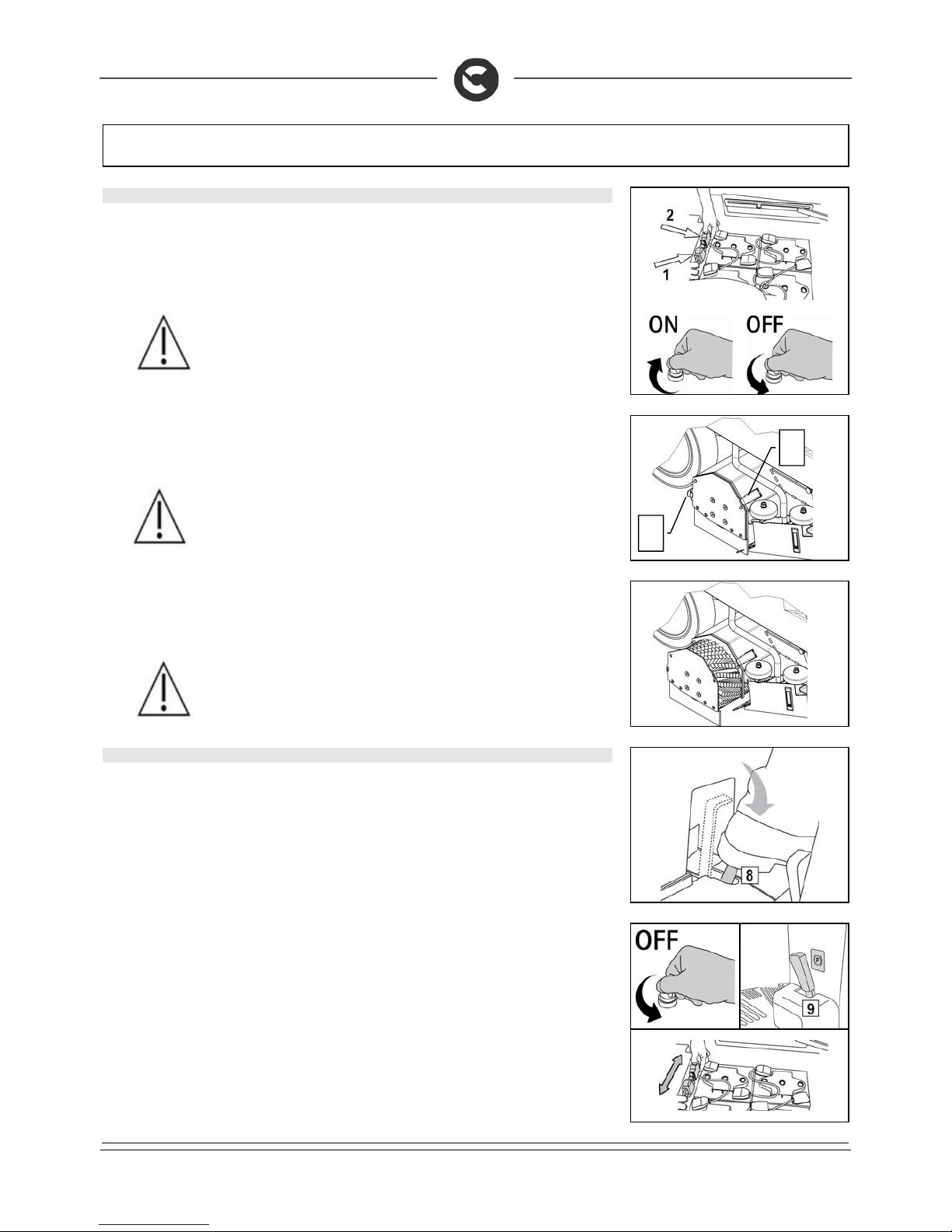
38. CYLINDRICAL BRUSH ASSEMBLY (INNOVA 2011 70 S)
1. Make sure the parking brake is engaged and that the main switch is OFF
2. Connect the battery connector
3. Turn the key to the "ON/I" position The base raises automatically.
4. Turn the key to the “OFF/0” position and remove it from the electrical board.
WARNING: during this operation, verify that there ar e no people or objec ts near
the brush.
5. With the base in the high position, release t he casing preassembly hinges stop (1) on the right of th e
base
6. Disconnect the right base casing from its location in the body of the base
ATTENTION: you are advised to always wear protective gloves, t o avoid the ris k
of serious injury to your hands
7. Insert the brush (the side wit h 5 teeth) in the tunnel until it c ouples with the dragging device hub on
the opposite side of the tunnel.
8. Insert the idler wheel of the right base casing in the brush
9. Attach the casing preassembly stop hinges (1) on the right of the base
WARNING: Pay attention to the direction of the brush bristles during
assembly, the point of the brush viewed from the abov e should be t owards the
front of the machine.
39. BRUSH HEAD EXTRA-PRESSURE (INNOVA 2011 65-75-85 B VERSIONS)
The pressure on the brushes can be increas ed by pressing pedal (8) located under the seat. Simply
release the pedal to return to the initial condition.
The pedal can also be locked in the maximum pressure position.
W
ARNING: The pedal must be released before lifting the brush head.
The pressure must be chosen according to the type of floor and the ex tent of the dirt. A pr essure inc rease
causes greater wear and tear of the brushes and higher energy consumption (for further information, read
“CHOOSING AND USING THE BRUSHES”)
If problems occur during work, turn the machine off, turn the key in the OFF position, eng age the parking
brake by moving the lever (9) to the left to stop the machine and disconn ect the battery connec tor locate d
under the operator. These commands block all mov ing mac hine parts. To resume work, o nce the prob lem
has been resolved, reconnect the connec tor, s tart the machine, turning the key in the ON pos itio n, release
the parking brake lever.
The machine will not start if the operator is not properly seated.
1
1
Page 25
25
MACHINE PREPARATION
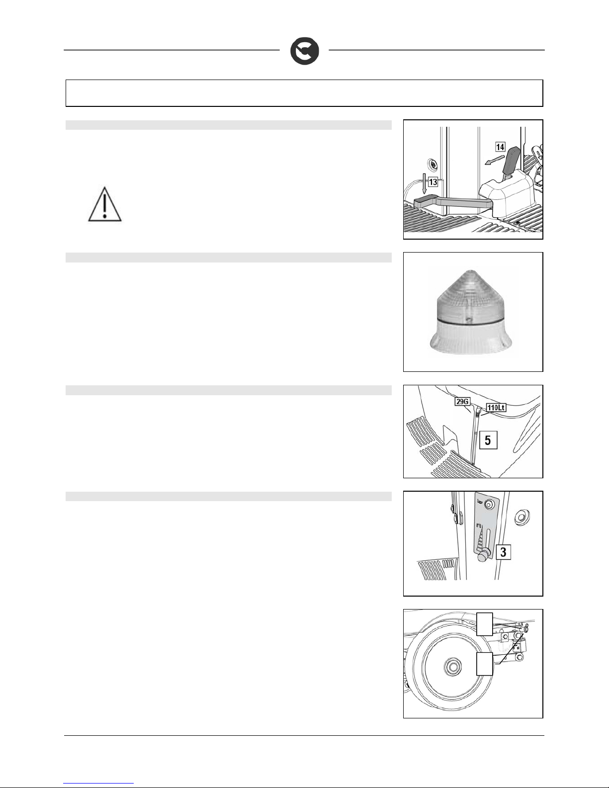
40. SERVICE BRAKE AND PARKING BRAKE
The machine has an electronic braking system. To brake, in normal conditions, just remove your foot from
the accelerator pedal. If this service brake is working badly, or if necess ary, activate the brake pe dal (13)
pushing it downwards. To engage the parking brak e, press the brake p edal (13) and lock it by pulling the
lever (14) to the left. The red indicator light on the instrument panel will switch on.
WARNING: to avoid any damage to the machine, always disengage the
parking brake before beginning to work or before making any transfer
manoeuvres.
41. FLASHING LIGHT (OPTIONAL)
The machine can be equipped with a flashing light tha t turns on automatically when the key in the main
switch is turned on.
42. EMPTY SOLUTION TANK DEVICE
To check the quantity of water in the solution t ank th ere is a s uitabl e lev el indic ator p ipe (5) placed in fro n t
of the driver seat.
43. KIT WATER MANAGEMENT (INNOVA 2011 60 B VERSIONS)
If you want to increase the working capacity of the machine, you can replace the detergent solution choke
bushing on the solenoid valve (optional) with the more suitable one included in the water management kit.
To do this, proceed as follows:
1. Make sure the solution tank is empty, otherwise empty it completely
2. Check that the main switch of the machine is set to “OFF”
3. Disconnect the battery connector cable from the machine connector.
4. Close the detergent solution tap (3)
5. Remove the screw tie (1) that fixes the solution distribution tube to the solenoid valve
6. Remove the solution distribution tube from the solenoid valve
7. If present, remove the solution choke bushing (2) and replace it with the more suitable one, or insert
the more suitable choke bushing at the required working capacity (the choke bushings are included in
the water management kit)
8. Reassemble all the elements
1
2
Page 26
26
WORK
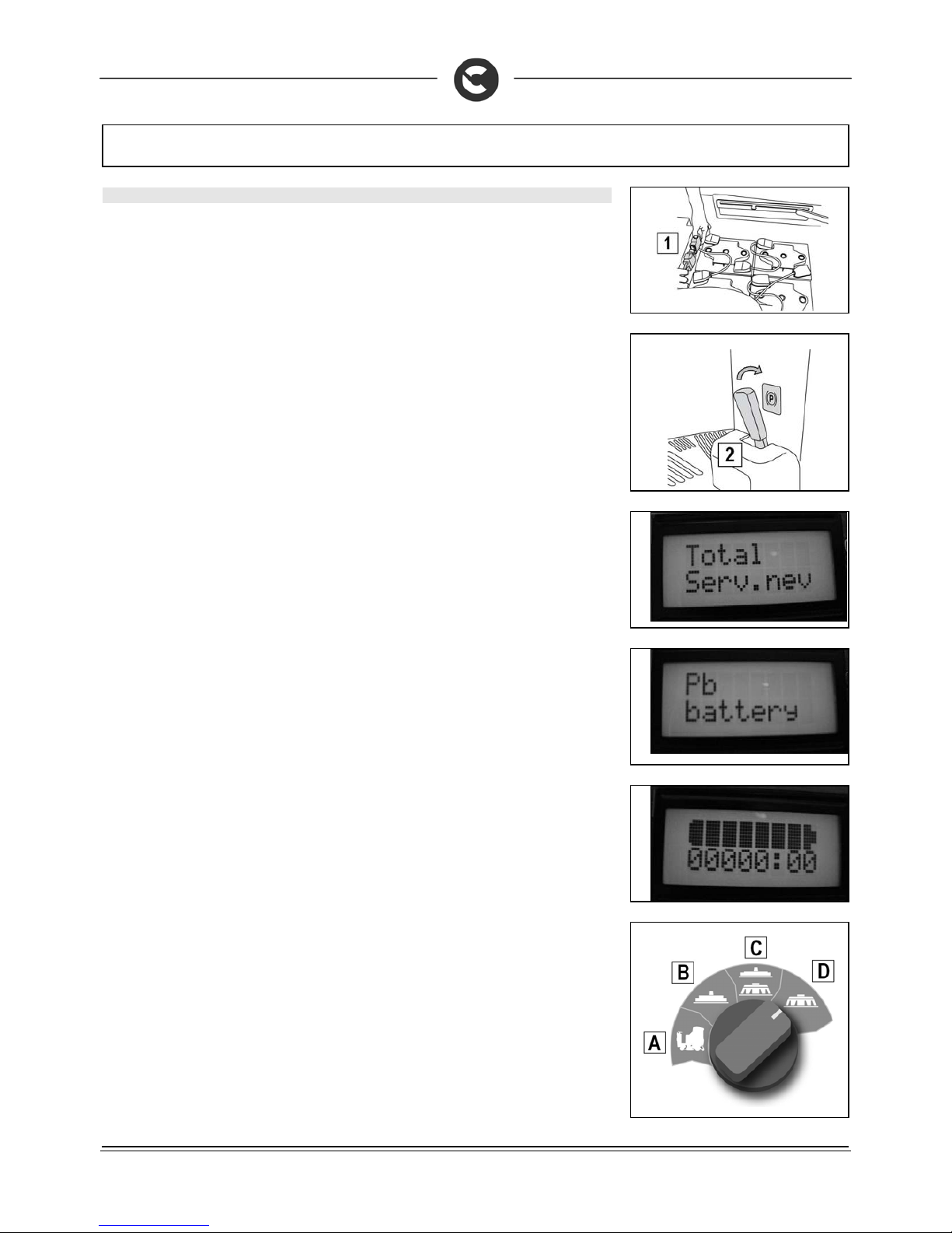
44. PREPARING TO WORK
1. Make sure the recovery tank is empty, otherwise empty it completely
2. Check that the main switch of the machine is set to "0"
3. Connect the connector to the batteries (1)
4. Sit on the driver’s seat
5. Check the parking brake is released (2).
6. Turn the key of the main switch a quarter of a turn clockwise (to position ON). Immediat ely, on the
instrument panel, the display will turn on indicating the charge level of the batteries.
7. With switch-on, three consecutive screens are vis u alis e d on t he monitor. The first screen shows (on
the top line) what type of hour-counter has been set; in this case it's a total hour-counter (to
visualise a different type - for instance partial - contact the qualified, COMAC-trained personnel) .
The bottom line shows the “service” setting (in this case there is no setting).
8. The second screen visualises what battery tec hnology has been set for mac hine operation; in this
case it's lead batteries (to set another type of batt ery - for instance gel - contact the qualified,
COMAC-trained personnel).
9. The third and last screen (known as “work”) visualises the battery charge status and the total
functioning time. When the batteries supplied are fully charged, the upper line contains 8 light
indicators that represent a battery. As the batteries gradually run down, the indicators go out a nd,
with the batteries completely run down, only the battery outline flashes. The bottom li ne indicates
the hours and minutes of functioning. The flashing “:” symbol indicates that the hour-counter is
counting the machine functioning time.
10. For Innova 2011 65-75-85 B versions, select the desired working program with the I-Drive device:
A. Transfer: movement of the machine without working
B. Drying: use the squeegee only
C. Washing / Drying: use both the brushes and the squeegee
D. Washing only: use brushes only
Page 27
27
WORK
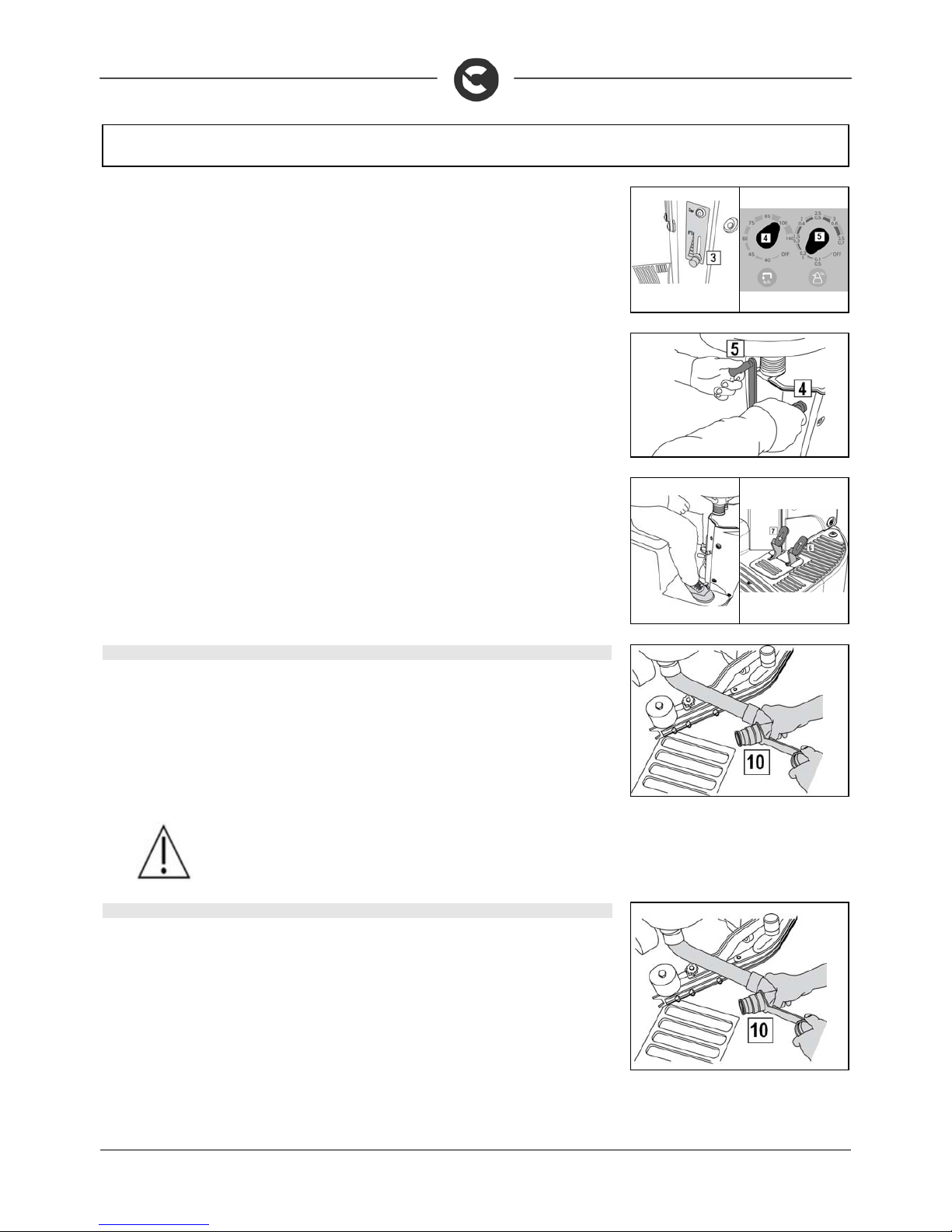
11. If the machine does not have the CDS device, move the tap lever (3) downwards and adj ust the
amount of desired solution.
12. If the CDS dosing system is present, the tap lever (3) must be opened full downwards completely
opening the flow of water. This lever should not be touched to make adjustments. To obtain t he
correct dose to the brushes, use the knobs only to adjust the amount of water solution (4) and
detergent (5). See paragraph “DETERGENT ADJUSTMENT WITH CDS SYSTEM”.
13. For Innova 2011 60 B versions, lower the brush head by turni ng the righthand lever (4) cloc kwise,
then lower the squeegee by turning the lefthand lever (5) counter-clockwise.
14. Pressing the accelerator pedal (6 - right pedal), the machine starts moving, both the squee gee and
the brush head lower and the brushes start to turn (if the i-drive sw itch is on the third working
program)
15. To perform a reversing manoeuvre, press both pedals (6 and 7), the squeegee will rise
automatically and the machine starts to move backwards
During the first meters, check there is sufficient solution and that the squeegee dries perfectly. The
machine will start working in good working order up to run out of detergent solution or unt il the battery is
discharged.
45. OVERFLOW DEVICE (INNOVA2011 60 B)
The machine is not equipped with an overfill device, b ecause the capacity of the rec overy tank is greater
than the capacity of the solution tank. In extraordinary cases, there is a mechanical device (float) on the lid
that, when the recovery tank is full, shuts off the air t o the suction mo tor intake TO pr otect it; the s ound of
the vacuum motor will then be deeper. If this happens, raise the squeeg ee by turning the left-hand leve r
clockwise. After about 15-25 seconds, switch off the suction motor by making a 1/4 turn of the key,
anticlockwise. Make a 1/4 turn of the key clockwise, and take the machine to the designated water
drainage area. Then proceed with emptying the recovery tank through a special drainage pipe (10). It is
good practice when restoring the level of th e solution t ank, to em pty the recovery tank thro ugh the s pecial
drainage pipe (10).
WARNING: during machine switch-on, do not keep the accelerator pedal
pressed down.
46. OVERFLOW DEVICE (INNOVA2011 65-75-85 B INNOVA2011 70 S)
The machine is not equipped with an overfill dev ice, because the capacit y of the recovery tank is grea ter
than the capacity of the solution tank. In extraordinary cases , there is a mechanic al dev ic e (float) on the lid
that, when the recovery tank is full, it shuts o ff the air to the sucti on motor int ake protecti ng it, in th is case
the sound of the suction motor will be deeper. In this case, turn the work ing knob to tr ansfe r (movemen t of
the machine without working), and the engi ne turns off after about 15-25 seconds. Then proceed with
emptying the recovery tank through a special drainage pipe (10).
It is good practice when restoring the level of the solu tion tank, to empty the recovery tank through the
special drainage pipe (10).
Page 28
28
AT THE END OF THE WORK
A
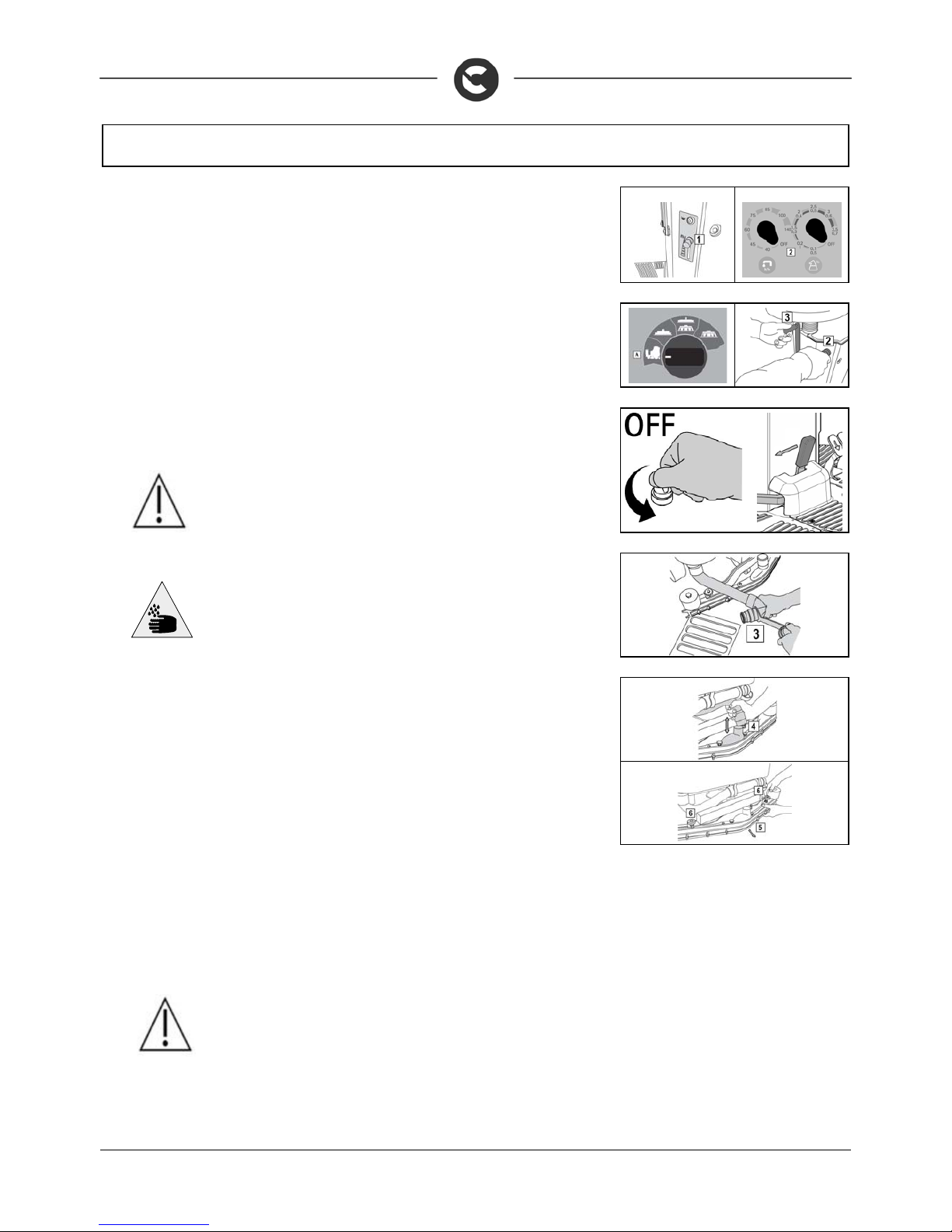
t the end of the work, and before carrying out an y t ype of m ain ten an ce, perfo rm the fo llo wi ng o pe ration s:
1. Close the tap (1) or turn the knob (2) to OFF in case of CDS dosing system.
2. Turn the I-DRIVE selector to the “Transfer” position for Inn ova 2011 65-75-85 B versions. Both
the brush head and the squeegee rise and after a few seconds the suction motor will turn off.
For Innova 2011 60 B versions, Raise the brush head by turning the rig ht-hand lever (2) anticlock wise.
Then raise the squeegee by turning the l eft-hand lev er (3) clock wise. Aft er about 15-25 se conds, switc h
off the suction motor by making a 1/4 turn of the key, anticlockwise.
3. Make a 1/4 turn of the key clockwise, and take t he machine to the designated water drainage
area
4. Turn the machine off by turning the key one quarter turn counter-clockwise and remove it from the panel.
5. Engage the parking brake
ATTENTION: Before performing any maintenance, remove the keys from th e
panel and disconnect the battery connector of the machine.
6. Disconnect the tube (3) from its seat, unscrew the drainage cap and empty the recovery tank.
WARNING: this operation must be carried out by using gloves in order to
protect against contact with dangerous solutions
7. Slide the suction tube (4) from the squeegee sleeve
8. Remove the squeegee (5) from the support arm by unscrewing the handwheel (6).
9. Clean well both the squeegee and the rubbers with a jet of water.
10. After cleaning the squeegee and rubbers, replace the squeegee on the initial support, firstly
inserting the left pin of the squeegee in the left slot of the arm, then the right pin i n the right slot,
being careful to keep the spring and washer on the plate of the arm. This can be simplified by first
loosening the handwheel on the pi n. Then re-tighten the handwheel to block the squeegee in
place.
11. Finally insert the squeegee tube in the special sleeve.
12. Lift the recovery tank and connect the battery connector
13. Sit on the driver’s seat
14. Insert the key into the ignition switch and turn it a quarter turn clockwise (to position ON)
15. Disengage the parking brake
16. Park the machine in a closed place, in a n area where it cannot cause da mage to people or other
property, but also be protected from an accidental fall of objects.
17. Engage the parking brake
18. Turn the ignition key a quarter turn counter-clockwise (OFF position) and remove the key
19. Lift the recovery tank and disconnect the battery connector
ATTENTION: do not leave the machine unattended without first removing the
start-up switch key and applying the parking brake. In add ition, do not park the
machine in open places or on sloping floors
Page 29
29
DAILY MAINTENANCE
PERFORM ALL MAINTENANCE OPERATIONS IN SEQUENCE
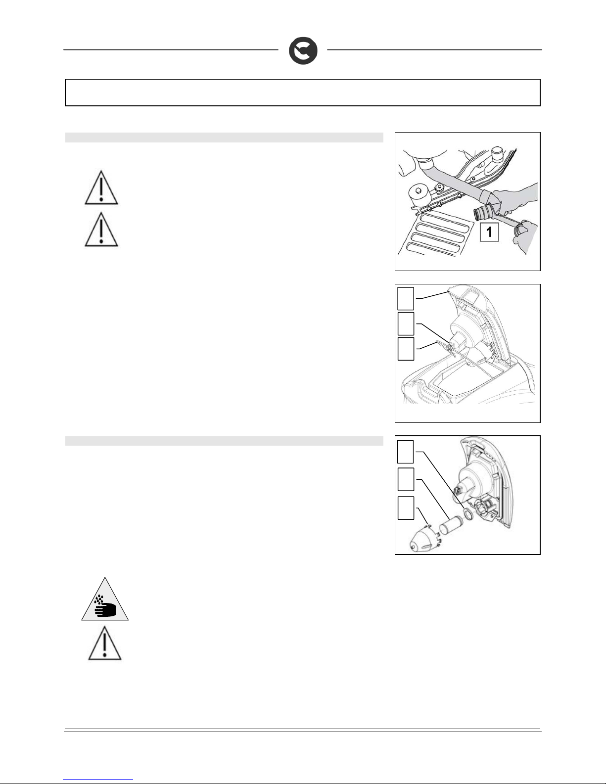
47. CLEANING THE RECOVERY TANK
1. Disconnect the tube (1) from its seat, unscrew the drainage cap and empty the recovery tank.
ATTENTION: Before performing any maintenance, remove the keys from th e
panel and disconnect the battery connector of the machine.
WARNING: this operation must be carried out wearing gloves to protect
against contact with dangerous solutions.
2. Raise the cap (2) until the hook (4) is secured to the prop (3) of the recovery tank.
3. Clean and rinse the recovery tank and the suction pipe (conn ecting pipe between the squeegee
and the tank).
4. Reposition the cap on the drainage tube and lower the suction cap. To lock the prop (3) just
slightly raise the cap, release the prop (3) and lower the cap up to close it.
48. CLEANING THE SUCTION MOTOR FILTER
1. Raise the suction cover (2) and block it with the stop (3)
2. Remove the suction filter protection (5) by rotating it clockwise
3. Release the retaining clips (6)
4. Remove the suction filter (7) from its seat
5. Use a jet of water to clean the walls and brush head of the filter
6. Reassemble all the elements
ATTENTION: These operations must be carried out using gloves to protect
against contact with dangerous solutions
ATTENTION: Before performing any maintenance, r emove the keys from t he
panel and disconnect the battery connector of the machine.
6
7
2 4 3 5
Page 30
30
DAILY MAINTENANCE
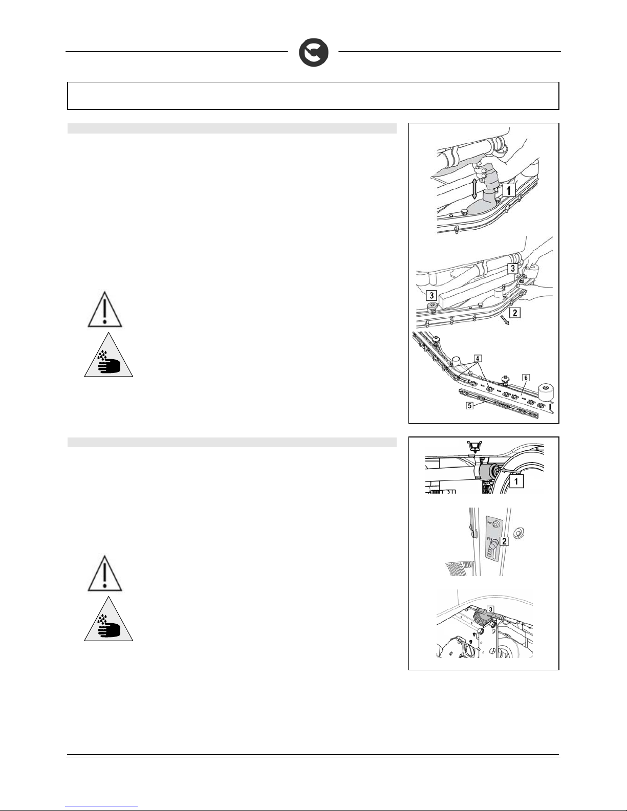
49. CLEANING THE SQUEEGEE
The careful cleaning of the whole suction group ensu res better drying and cleaning of the floor as well
as greater duration of the suction motor. Proceed as follows for cleaning:
1. Slide the suction tube (1) from the squeegee sleeve.
2. Remove the squeegee (2) from the support arm by unscrewing the handwheel (3).
3. Check the wear of the rubbers. If the edge of the rubber is ruin ed, the rear rubber can be turne d
on all four corners. If the rubbers are comp letely worn proceed with the replacement. To remov e
the rubber, turn the wing nuts (4) in a horizontal position, remove the rubber-pressing blade (5)
and then remove the rubber to turn it or replace it.
4. Proceed in reverse to replace the rubber.
5. After cleaning, replace the squeegee (2) on the initial s upport, firstly inserting the left pin of the
squeegee in the left slot of the arm, the n the right pin in the right sl ot, being careful to keep the
spring and washer on the plate of the arm. This can be s implif ied by first loosening the handwheel
(3) on the pin. Then re-tighten the handwheel (3) to block the squeegee in place.
6. Finally insert the squeegee tube in the special sleeve.
ATTENTION: Before performing any maintenance, remove the keys from th e
panel and disconnect the battery connector of the machine.
ATTENTION: These operations must be carried out using gloves to p rotect
against contact with dangerous solutions
50. CLEANING THE SOLUTION TANK AND FILTER
1. Disconnect the clean water drainage pipe (1) fro m its housing on the left side of the machine,
unscrew the cap and empty the tank.
2. Remove the plug from the solution tank refill opening.
3. Rinse the inside of the tank with a jet of water.
4. Close the drainage pipe with the cap and put it in place.
5. Close the water tap (2).
6. Unscrew the filter (3) at the front of the machine.
7. Remove the internal filter cartridge and rinse everything thoroughly with running water.
8. Reassemble all the elements.
ATTENTION: Before performing any maintenance, remove the keys from th e
panel and disconnect the battery connector of the machine.
ATTENTION: These operations must be carried out using gloves to p rotect
against contact with dangerous solutions
Page 31
31
DAILY MAINTENANCE
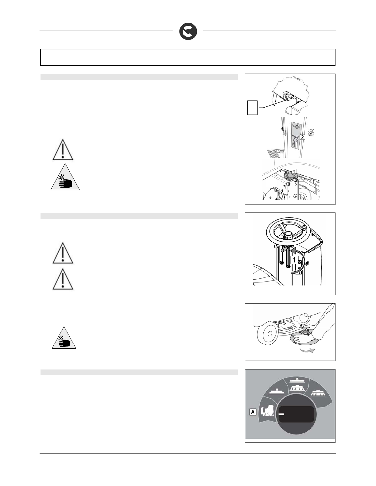
51. CLEANING THE FILTER AND SOLUTION TANK (S VERSION)
1. Remove the drainage cap (1) and empty the tank
2. remove the plug from the solution tank refill opening
3. rinse the inside of the tank with a jet of water
4. Close the drainage pipe with the cap and put it in place.
5. Close the water tap (2).
6. Unscrew the filter (3) at the front of the machine.
7. Remove the internal filter cartridge and rinse everything thoroughly with running water.
8. Reassemble all the elements.
ATTENTION: Before performing any maintenance, remove the keys from th e
panel and disconnect the battery connector of the machine.
ATTENTION: These operations must be carried out using gloves to p rotect
against contact with dangerous solutions
52. DISC BRUSH ASSEMBLY (INNOVA 2011 60 B VERSIONS)
1. Raise the brush head by turni ng the righthand lever (1 ) for the counter-clock wise movement of the
brush head.
ATTENTION: Before performing any maintenance, remove the keys from the
panel and disconnect the battery connector of the machine.
WARNING: during this operation, verify that there are no people or obj ects near
the brush.
2. Rotate the brush counter-clockwise until i t comes out of the brush-holder plate seat, as shown in
the figure.
ATTENTION: you are advised to always wear protective gloves, to avoid the risk
of serious injury to your hands
53. DISC BRUSH DISASSEMBLY (INNOVA 2011 65-75-85 B VERSIONS)
1. Turn the key to the ON/I position.
2. Turn the I-DRIVE selector to the “Transfer” position. The brush head will lift if not already lifted.
3. Turn the key to the “OFF/0” position and remove it from the electrical board.
4. Rotate the brush counter-clockwise until i t comes out of the brush-holder plate seat, as shown in
the figure. The photo shows the direction of rotati on for releasing the right brush. Rotate in the
opposite direction for the left brush.
1
Page 32
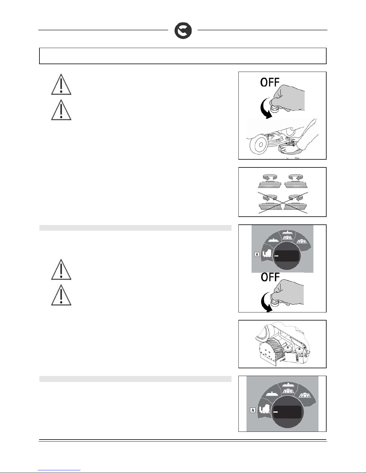
32
DAILY MAINTENANCE
WARNING: Before performing any maintenance, remove the k eys from the
panel and disconnect the battery connector of the machine.
WARNING: This operation must be carried out using gloves to protect agains t
contact with dangerous solutions.
You are advised to invert the right and left-hand brus h es ev ery day . If the brus hes are n ot new howev er,
and have deformed bristles, it is better to reassemble them in the s ame position (the right-han d one on
the right, and the left-hand one on the left), to prevent the different inc lination of the bristles prod ucing
an overload on the brush motor as well as excessive vibrations.
54. DISASSEMBLY OF CYLINDRICAL BRUSHES (S VERSIONS)
1. Turn the key to the ON/I position.
2. Turn the I-DRIVE selector to the “Transfer” position. The base will lift if not already lifted.
3. Turn the key to the “OFF/0” position and remove it from the electrical board.
WARNING: Before performing any maintenance, remove the k eys from the
panel and disconnect the battery connector of the machine.
WARNING: This operation must be carried out using gloves to protect agains t
contact with dangerous solutions.
4. With the base in the high posit ion, release the casing preassemb ly hinges stop on the right of the
base
5. Disconnect the right base casing from its location in the body of the base
6. Remove the brushes from the tunnel, clean with a water jet and rep lace them. Check the bristles
are not worn; in the event of excessive wear, replace the brushes (the bristles should be at least
10mm long)
7. Clean the side rubber splash guards of the base
8. reassemble all the elements.
55. CLEANING DEBRIS HOPPER (S VERSIONS)
1. Turn the key to the ON/I position.
2. Turn the I-DRIVE selector to the “Transfer” position. The base will lift if not already lifted.
3. Turn the key to the “OFF/0” position and remove it from the electrical board.
Page 33
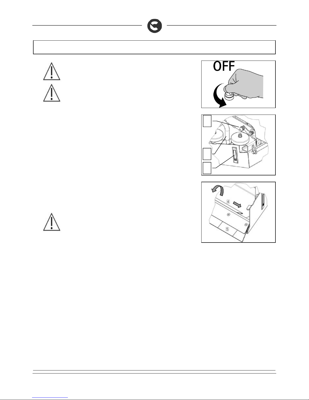
33
DAILY MAINTENANCE
WARNING: Before performing any maintenance, remove the k eys from the
panel and disconnect the battery connector of the machine.
WARNING: This operation must be carried out using gloves to protect agains t
contact with dangerous solutions.
4. Disconnect the hopper suction hose (1)
5. Turn the knob (2) counter-clockwise until the hopper locking lever allow its extraction
6. Using the flush handle (3) remove the hopper and empty it
7. Check the wear of the rubber (5) and clean it with a jet of water
8. Turn the hopper suction filter (4) counter-clockwis e, pulling it tow ards the s uction hose an d extrac t it
from the retainer pin
9. Clean underneath with a jet of water and check it is working correctly
10. reassemble all the elements.
WARNING: If the rubber is worn, contact a qualified FIMAP technic ian for its
replacement
3
1
2
Page 34
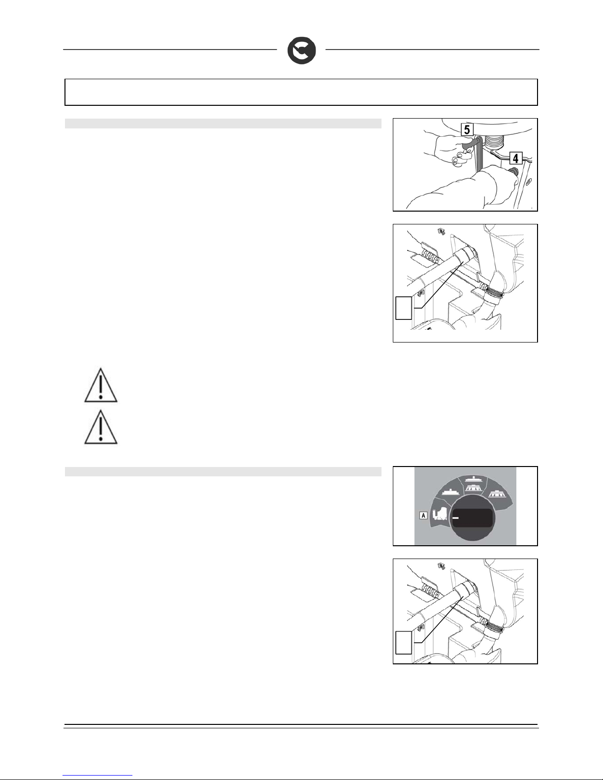
34
WEEKLY MAINTENANCE
56. CLEANING OF THE SUCTION HOSE (INNOVA 2011 60 B VERSIONS)
Whenever suction seems to be unsatisfactory, check that the suction tube (1) is not obstructed. If
necessary clean with a jet of water as follows:
1. Make sure the recovery tank is empty, otherwise empty it
2. Turn the key to the “OFF/0” position and remove it from the electrical board.
3. Raise the squeegee body from the ground by turning lever (5) clockwise
4. Raise the brush head body from the ground by turning lever (4) counter-clockwise
5. Remove the tube from the squeegee suction nozzle
6. Grip the handle under the seat to open the recovery tank.
7. Lift the recovery tank until it hooks to the end of the safety clamp.
8. Detach the aspiration tube from the seat on the recuperation tank (1)
9. Clean it with a water jet introduced from the side where it is connected to the tank
10. Reassemble all the elements
WARNING: Before performing any maintenance, remove the k eys from the
panel and disconnect the battery connector of the machine.
WARNING: This operation must be carried out using gloves to protect agains t
contact with dangerous solutions.
57. CLEANING OF THE SUCTION HOSE (INNOVA 2011 65-75-85 B VERSIONS)
Whenever suction seems to be unsatisfactory, check that the suction tube (1) is not obstructed. If
necessary clean with a jet of water as follows:
1. Make sure the recovery tank is empty, otherwise empty it completely
2. Turn the key to the ON/I position.
3. Turn the I-DRIVE selector to the “Transfer” position. The brush head will lift if not already lifted.
4. Turn the key to the “OFF/0” position and remove it from the electrical board.
5. Remove the tube from the squeegee suction nozzle
6. Make sure the recovery tank is empty, otherwise empty it completely
7. Grip the handle under the seat to open the recovery tank.
8. Lift the recovery tank until it hooks to the end of the safety clamp.
9. Detach the aspiration tube from the seat on the recuperation tank (1)
10. Clean it with a water jet introduced from the side where it is connected to the tank
11. reassemble all the elements.
1
1
Page 35
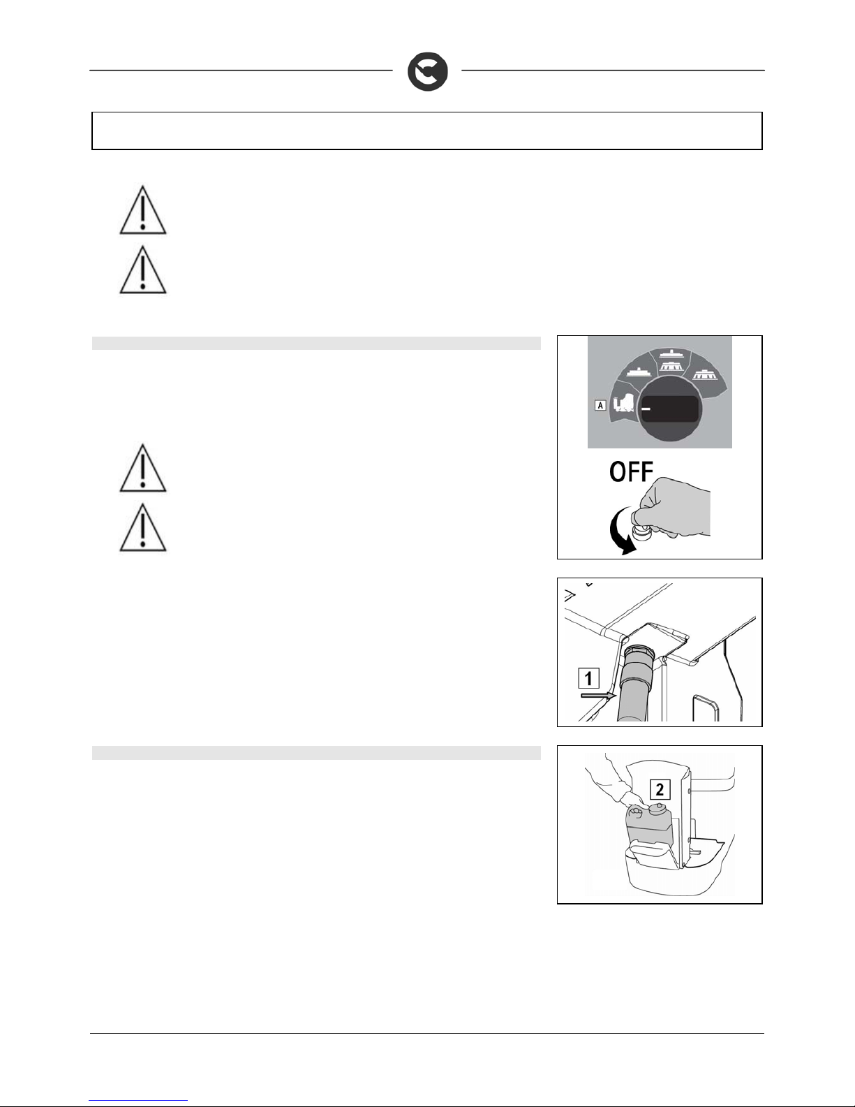
35
WEEKLY MAINTENANCE
WARNING: Before performing any maintenance, remove the k eys from the
panel and disconnect the battery connector of the machine.
WARNING: This operation must be carried out using gloves to protect agains t
contact with dangerous solutions.
58. CLEANING OF THE SUCTION HOSE (S VERSIONS)
Whenever suction seems to be unsatisfactory, check that the suction tube (1) is not obstructed. If
necessary clean with a jet of water as follows:
1. Turn the key to the ON/I position.
2. Turn the I-DRIVE selector to the “Transfer” position. The base will lift if not already lifted.
3. Turn the key to the “OFF/0” position and remove it from the electrical board.
WARNING: Before performing any maintenance, remove the k eys from the
panel and disconnect the battery connector of the machine.
WARNING: This operation must be carried out using gloves to protect agains t
contact with dangerous solutions.
4. Remove the suction hose from the squeegee nozzle
5. Remove the suction hose from the waste collection tray
6. Make sure the recovery tank is empty, otherwise empty it completely
7. Grip the handle under the seat to open the recovery tank.
8. Lift the recovery tank until it hooks to the end of the safety clamp.
9. Detach the aspiration tube from the seat on the recuperation tank (1)
10. Clean it with a water jet introduced from the side where it is connected to the tank
11. Reassemble all the elements.
59. CLEANING OF THE DETERGENT CANISTER (VERSIONS WITH CDS)
The detergent canister must be carefully cleaned at least once a week in order to keep the machine in
perfect working order:
1. Turn the key to the “OFF/0” position and remove it from the electrical board.
2. Open the compartment at the front of the machine (2)
3. Unscrew the detergent filler cap
4. Remove the tank and clean any residue of detergent.
5. Place the canister in the compartment an d t igh ten the cap, making sure that the det erge nt suction
pipe touches the bottom.
6. Close the compartment door.
Page 36
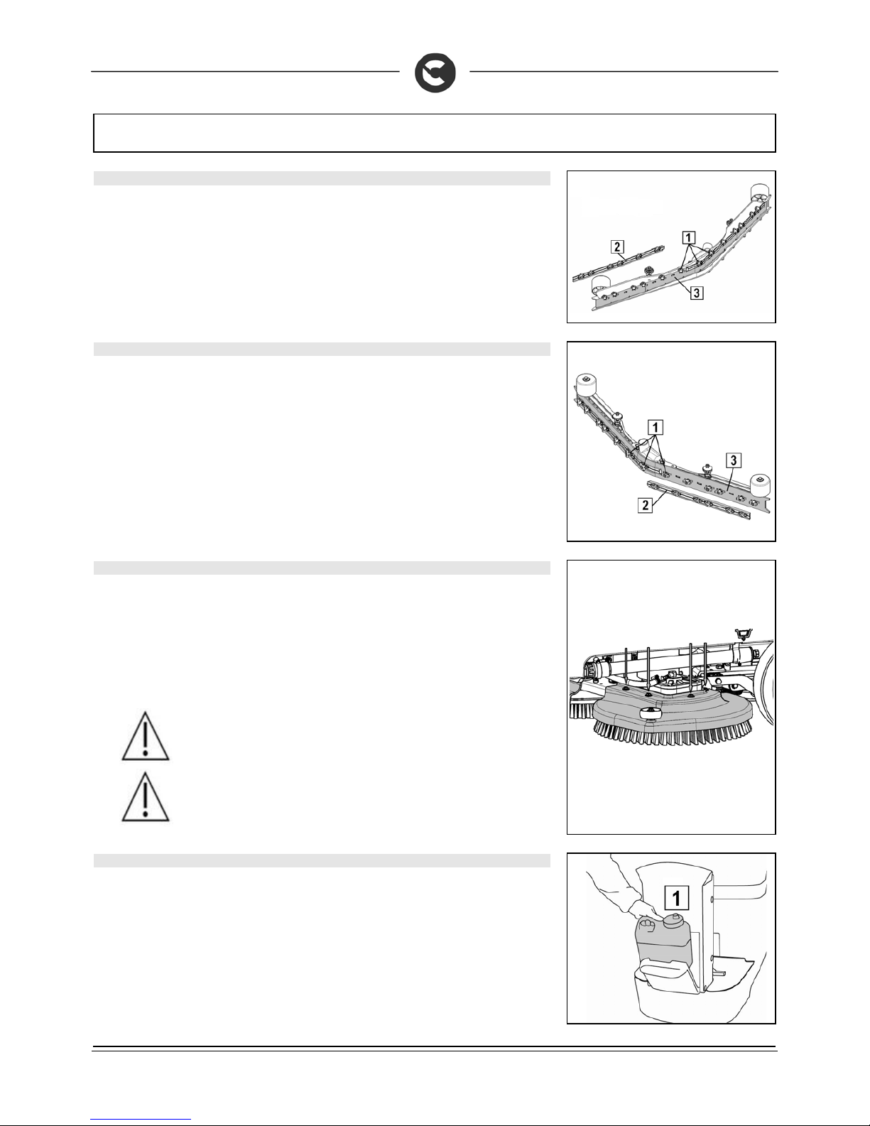
36
EXTRAORDINARY MAINTENANCE
60. REPLACING THE FRONT SQUEEGEE RUBBER
Suction will be poor and the machine will not dry perfectly if the front squeegee rubber is worn. Proceed
as follows to replace:
1. Turn the key to the “OFF/0” position and remove it from the electrical board.
2. Remove the squeegee from the support arm by unscrewing the handwheel.
3. Turn the wing nuts (1) in the horizontal position.
4. Remove the front rubber-pressing blades (2).
5. Remove the rubber (3) and replace it.
6. Proceed in reverse to replace the rubber.
61. REPLACING THE REAR SQUEEGEE RUBBER
If the squeegee rear rubber is worn and does not dry well, it is pos sible to chan ge the dry ing e dge us ing
one of the 4 edges of the rubber.
This operation can be done both with a squeegee fitted or removed as follows:
1. Turn the key to the “OFF/0” position and remove it from the electrical board.
2. Turn the wing nuts (1) in the horizontal position.
3. Remove the rear rubber-pressing blades (2).
4. Remove the rubber (3) and replace it.
5. Proceed in reverse to replace the rubber
6. adjust the height of the squeegee depending on the rubber (see “ADJ USTING THE HEIGHT OF
THE SQUEEGEE SUPPORT”)
62. REPLACEMENT OF THE BRUSH HEAD CASING
Periodically check the condition of the brus h head c asings that serv e as protection to the r otation of the
brushes. To replace proceed as follows:
1. Make sure that the brush head body is lowered, otherwise lower it
2. Turn the key to the “OFF/0” position and remove it from the electrical board.
3. Ensure to remove the screws securing the casing
4. Dismantle the casings
5. Fit the new casings with the screws previously removed
WARNING: Before performing any maintenance, remove the keys from the
panel and disconnect the battery connector of the machine.
WARNING: The housing can prevent damage to persons or property. Alway s
check for wear.
63. CLEANING OF THE DOSING SYSTEM (VERSIONS WITH CDS)
The dosing system should be cleaned when the machine is not used for a long period (more than 48 hours); to
do so, proceed as follows:
1. Check that the main switch is in the “Off – 0” position
2. Check that the battery connector is disconnected from the machine connector
3. Check the parking brake is correctly engaged
4. Make sure the recovery tank is empty, otherwise empty it
5. Open the detergent canister compartment (1) located in front of the steering column
Page 37
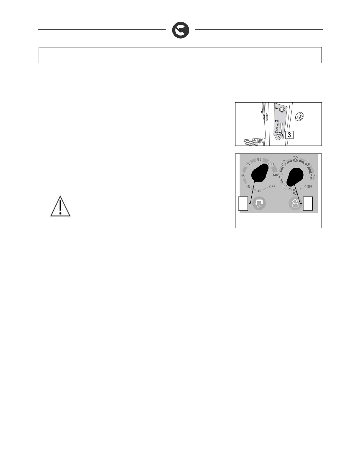
37
EXTRAORDINARY MAINTENANCE
6. Unscrew the detergent tank cap and fill the tank with clean water
7. Close the lid of the detergent tank, taking care that the suction filter is positioned at the bottom of
the tank. Reposition it in the tank compartment
8. Check there is clean water in the solution tank
9. Check that the water tap is turned on fully (3)
10. Check that the by-pass tap is in the “dosing system” position
11. Turn the water flow rate adjustment knob (1) to the maximum position
12. Turn the detergent percentage adjustment knob (2) to the maximum position
13. Insert the battery connector into the machine connector.
14. Place the main switch in position “ON – I”
15. Disengage the parking brake
16. Select the "Wash only" program with the I-Drive device
17. Press the forward movement pedal to activate the brush head and the dosi ng system
18. Wait a few moments with the dead man's lever pressed (normally 2 to 4 seconds) to allow the
cleaning of the dosing system
19. Completely empty the solution tank and the detergent canister
20. Park the machine in a safe manner
WARNING: The machine will deliver solution during this operation
1
2
Page 38
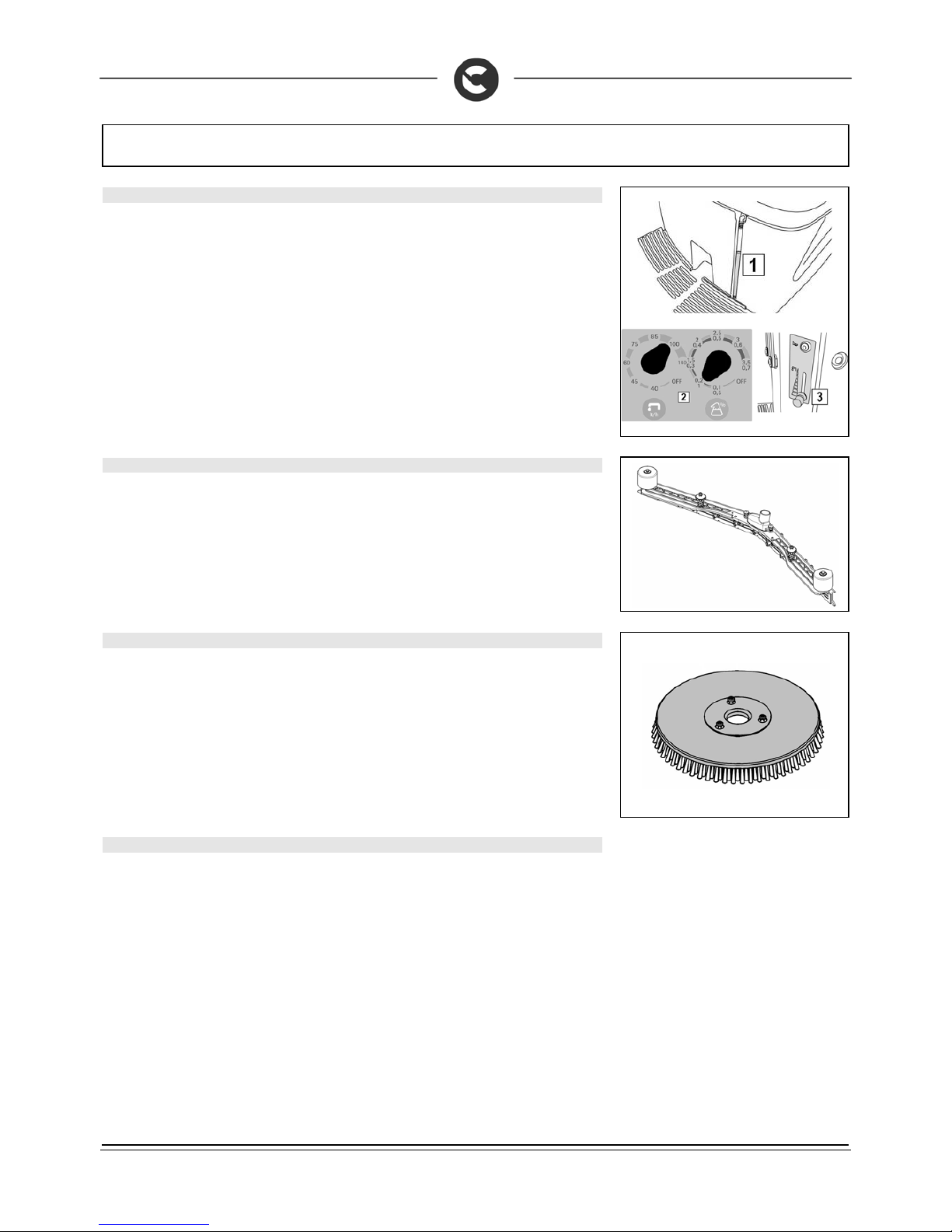
38
TROUBLESHOOTING
64. INSUFFICIENT WATER ON THE BRUSHES
1. Check there is water in the solution tank (1).
2. Check that the water / detergent selectors (2) and tap (3) are open for the CDS versions.
3. Check that the tap (3) is turned on for versions without CDS.
4. Clean the solution filter located at the front of the machine.
5. Check if the choke bushi ng is not blocked for the Innova 2011 60 B versions with “ KIT WATER
MANAGEMENT”
65. THE SQUEEGEE DOES NOT DRY PERFECTLY
1. Check the squeegee is clean
2. Check the regulation of the squeegee (see “MACHINE PREPARATION”)
3. Clean the entire suction unit (see “WEEKLY MAINTENANCE”)
4. Replace the rubbers, if worn
66. THE MACHINE DOES NOT CLEAN WELL
1. Check the state of wear and tear of the brushes and, if nec essary, replace them. The brushes
should be changed when the bristles are about 15mm long. To replace them, see “REPLACING
THE BRUSHES”, or “DISASSEMBLING THE BRUSHES” and “ASSEMBLING THE BRUSHES”.
Working with over-worn brushes may cause damage to the floor.
2. Use a different kind of brush to the one fitted as standard. For cleanin g floors where the dirt is
particularly resistant, we recommend the use of special brushes supplied upon request and
according to needs (see “CHOOSING AND USING THE BRUSHES”).
67. EXCESSIVE FOAM PRODUCTION
Check that a low foam detergent has been used. If neces sary, add a small quant ity of antifoam l iquid to
the recovery tank.
Remember that, when the floor is not very dirty, mo re foam is generated. In this case the detergent
solution should be more diluted.
Page 39
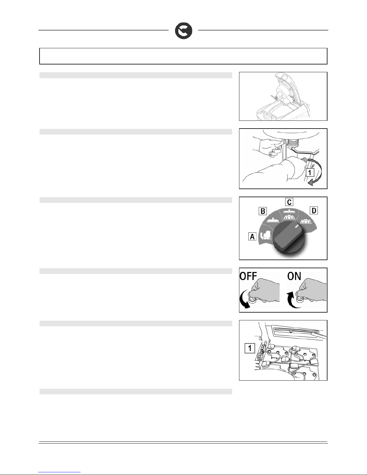
39
TROUBLESHOOTING
68. THE SUCTION DOES NOT FUNCTION
1. Check whether the recovery tank is full and, if necessary, empty it.
2. Check the float switch on the suction cap (see also “CLEANING THE RECOVERY TANK” in the
chapter “DAILY MAINTENANCE”).
69. THE BRUSHES MOTOR DOES NOT FUNCTION (INNOVA 2011 60 B VERSIONS)
ATTENTION To avoid damaging the floor, the motor only starts up when the machine is moved forwards
1. Check that during the forward mov ement of th e brush hea d is lowered using the r ighthand lev er (1)
rotated clockwise.
2. The operator must be properly seated in the driving position
3. Check no thermal protection device has intervened.
4. Check the correct connection of the motor to the terminal under the footboards.
70. THE BRUSHES MOTOR DOES NOT FUNCTION (INNOVA 2011 65 -75-85 B VERSIONS)
ATTENTION To avoid damaging the floor, the motor only starts up when the machine is moved forwards
1. Check that the brush head is lowered during start-up.
2. The operator must be properly seated in the driving position.
3. Check that the I-DRIVE selector is on "C" or "D" (brushes operating function).
4. Check no thermal protection device has intervened.
5. Check the correct connection of the motor to the terminal under the footboards.
71. IT IS IMPOSSIBLE TO RAISE OR LOWER THE BRUSH HEAD OR SQUEEGEE
The machine is fitted with electrical protection devices that control the brush head and squeegee
ascent/descent motor reducers. In the event of overloading, the fuses interrupt the power supply. After
checking and removing the reason for th e problem, to reset them just switch the mach ine off then on
again. If the problem persists, contact the COMAC technical assistance centre.
72. THE MACHINE DOES NOT START
1. Check that connector (1) is connected to the batteries.
2. Check the key switch is ON/I.
3. Check that batteries are charged.
73. ELECTRIC FUSES AND THERMAL CUT-OUTS
In addition to general 80 A fuses, the machine is also fitted with self-restorin g safety fuses located on
the boards in the electric system that interrupt the power supply to the brush and suction motors when
the machine exceeds the predetermined load. To restore th e power supply to the motor, switch off th e
machine and wait for the fuses to cool down (about 40 seconds). If the switch disconnects the curren t
several times in a row, contact the COMAC technical as s is tanc e centre.
Page 40
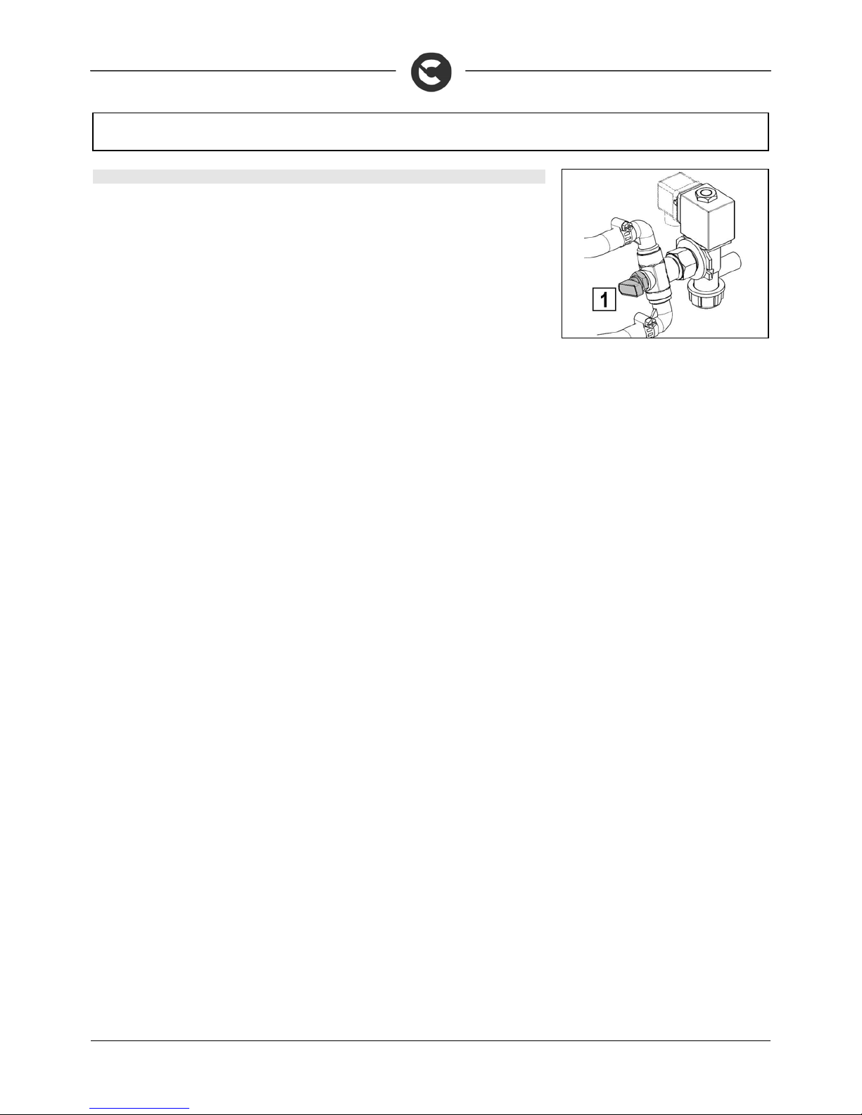
40
TROUBLESHOOTING
74. THE AUTOMATIC WATER/DETERGENT DOSING SYSTEM DOES NOT WORK
The automatic water/detergent dosing system has been designed with criteria of extreme sturdiness and
reliability, but there is a special by-pass system that allows you to use the machine even if the system is
out-of-use.
To b
y
-pass the automatic water/detergent dosing system, you must rotate the tap lever (1) on the rear-centre
of the brush head downwards; in this way you can go on working even with the system out-of-use. Remember,
however, to put not only water in the solution tank, but the right quantities of both water and detergent. With the
dosing system out-of-use, the water flow is regulated via the tap on the steering column.
Contact an Authorised Retailer to have the system repaired.
Page 41

41
DISPOSAL
To dispose of the machine, take it to a demolition centre or an authorised collection centre.
Before scrapping the machine it is necessary to remove and separ ate the following materials and send
them to the appropriate collection centres in accordanc e with the environmental hygiene regulations
currently in force:
brushes
filter
electric and electronic parts*
batteries
plastic parts (tanks and handlebars)
metal parts (levers and frame)
(*) In particular, to scrap the electric and electronic parts, contact your area distributor
Page 42

42
CHOOSING AND USING THE BRUSHES
POLYPROPYLENE BRUSH (PPL)
Used on all types of floors. Good resistance to w ear and tear, and hot water (no greater than 60°C). The Polypropy lene brush is non-hygroscopic and
therefore retains its characteristics even when working in wet conditions.
NYLON BRUSH
Used on all types of floors. Excellent resistance to wear and t ear, and hot water (even over 60°C). The nylon is hygroscopic and so tends to lose its
characteristics over time when working in wet conditions.
ABRASIVE BRUSH
The bristles of this type of brush are charged with highly aggressiv e abras ives . It is used to clean v ery dirty floors. To avoi d flo or damage, work onl y with the
pressure strictly necessary.
THICKNESS OF THE BRISTLES
Thicker bristles are more rigid and are therefore used on smooth floors or floors with small joints.
On uneven floors or those with deep joints, it is advisable to use softer bristles which can enter the gaps more easily.
Remember that when the bristles are worn an d therefore too s hort, they will b ecome rigid and are no lon ger able to pe netrate and cl ean deep d own. In this
case, like with overlarge bristles, the brush tends to jump.
PAD HOLDER
The pad holder is recommended for cleaning shiny surfaces.
There are two types of pad holder:
1. the traditional pad holder is fitted with a series of anchor points that allow the abrasive floor pad to be held and dragged while working
2. the CENTRE LOCK type pad holder not only has anchor points, but also a snap-type central locking system in plastic that allows the abrasive floor
pad to be perfectly centred and held wit hout any risk of it b ecoming detac hed. This type of dr agging device is recommended abov e all for machines
with more than one brush, where the centring of the abrasive discs is difficult.
TABLE FOR CHOOSING THE BRUSHES
Machine No. Brush Code Type of bristles
Bristl
Brush.
Length Notes
INNOVA 60 1
405630
405629
405627
405628
405519
PPL
PPL
NYLON
TYNEX (ABRASIVE)
PAD HOLDER
0.6
0.9
0.9
610
610
610
610
585
CENTER LOCK
INNOVA 65 2
422189
422971
422972
422981
422973
PPL
PPL
PPL
TYNEX (ABRASIVE)
PAD HOLDER
0.3
0.6
0.9
340
340
340
340
330
CENTER LOCK
INNOVA 75 2
427715
427716
427717
427719
427718
PPL
PPL
PPL
TYNEX (ABRASIVE)
PAD HOLDER
0.3
0.6
0.9
390
390
390
390
380
CENTER LOCK
INNOVA 85 2
430696
430697
430698
430699
431122
PPL
PPL
PPL
TYNEX (ABRASIVE)
PAD HOLDER
0.3
0.6
0.9
430
430
430
430
410
CENTER LOCK
INNOVA 70 1
431774
432423
432425
PPL
PPL
TYNEX MIXED STEEL
0.8
1
0.6 + 1
210 690
Page 43

43
EC DECLARATION OF CONFORMITY
The undersigned manufacturer:
COMAC S.p.A.
Via Maestri del Lavoro, 13
37059 Santa Maria di Zevio (VR)
declares under its sole responsibility that the product
SCRUBBING MACHINES
mod. INNOVA 2011 60 B - INNOVA 2011 65 B - INNOVA 2011 75 B - INNOVA 2011 85 B
complies with the requirements of the following Directives:
2006/42/EC: Machinery Directive
2006/95/EC: Low Voltage Directive
2004/108/EC: Electromagnetic Compatibility Directive
They also comply with the following standards:
EN 60335-1: Household and similar electrical appliances - Safety. Part 1: Generic standards
EN 60335-2-72: Household and similar electrical appli ances. Part 2: Generic standards for automat ic machines for floor treatment for commercial and
industrial use
EN 60335-2-29: Household and similar electrical appliances. Part 2: Special standards for battery chargers.
EN 12100-1: Machine safety - Fundamental concepts, fundamental principles of design - Part 1: Basic terminology and methodology
EN 12100-2: Machine safety - Fundamental concepts, fundamental principles of design - Part 2: Technical principles
EN 61000-6-2: Electromagnetic compatibility (EMC) - Part 6-2: Generic standards – Immunity for industrial environments.
EN 61000-6-3: Electromagnetic compatibility (EMC) - Part 6- 3: Generic standards — Stand ard emission for residential, c ommercial and light-industri al
environments.
EN 61000-3-2: Electromagnetic compatibility (EMC) - Part 3-2: Limits – Limits for harmonic current emissions (Equipment with input current 16 A per phase).
EN 61000-3-3: Electromagnetic compatibility (EMC) - Part 3-3: Limits – Res triction of volta ge variations and flicker in low v oltage power supp ly sys tems
for devices with a rated current 16 A.
EN 55014-1: Electromagnetic compatibility - Regulations for household appliances, electrical devices and similar equipment. Part 1: Emission -
Regulation for product family.
EN 55014-2: Electromagnetic compatibility - Regulations for household appliances, electrical devices and similar equipment. Part 2: Immunity -
Regulation for product family.
EN 62233: Household and similar electrical appliances - Electromagnetic fields Methods for evaluation and measurement
The person authorised to compile the technical file:
Sig. Giancarlo Ruffo
Via Maestri del Lavoro, 13
37059 Santa Maria di Zevio (VR) - ITALY
Santa Maria di Zevio (VR), 08/06/2012
COMAC S.p.A.
Legal representative
Giancarlo Ruffo
COMAC spa
Via Maestri del Lavoro, 13 – 37059 Santa Maria di Zevio – Verona – ITALY
Tel. +39 045 8774222 – Fax +39 045 8750303 - E-mail:[email protected]
or [email protected] - www.comac.it
Page 44

44
EC DECLARATION OF CONFORMITY
The undersigned manufacturer:
COMAC S.p.A.
Via Maestri del Lavoro, 13
37059 Santa Maria di Zevio (VR)
declares under its sole responsibility that the product
SCRUBBING MACHINES
mod. INNOVA 2011 70 S
comply with the requirements of the following Directives:
2006/42/EC: Machinery Directive
2006/95/EC: Low Voltage Directive
2004/108/EC: Electromagnetic Compatibility Directive
2000/14/EC: Directive by the European Parliament and Council date 8th May, 2000. Noise emission by machines and equipment for outdoor use.
Falling into the category of roadsweeper as defined in Annex 46 of Directive 2000/14/EC of the Europea n Parliament and the Council, is subject to nois e
marking only.
The conformity evaluation was carried out in accordance with enclosure III.B.46 of the said directive.
MODEL LwA [dB(A)] LwA, guaranteed [dB(A)]
They also comply with the following standards:
EN 60335-1: Household and similar electrical appliances - Safety. Part 1: Generic standards.
EN 60335-2-72: Household and similar electrical appli ances. Part 2: Generic standards for automat ic machines for floor treatment for commercial and
industrial use.
EN 60335-2-29: Household and similar electrical appliances. Part 2: Special standards for battery chargers.
EN 12100-1: Machine safety - Fundamental concepts, fundamental principles of design - Part 1: Basic terminology and methodology.
EN 12100-2: Machine safety - Fundamental concepts, fundamental principles of design - Part 2: Technical principles.
EN 61000-6-2: Electromagnetic compatibility (EMC) - Part 6-2: Generic standards – Immunity for industrial environments.
EN 61000-6-3: Electromagnetic compatibility (EMC) - Part 6- 3: Generic standards — Stand ard emission for residential, c ommercial and light-industri al
environments.
EN 61000-3-2: Electromagnetic compatibility (EMC) - Part 3-2: Limits – Limits for harmonic current emissions (Equipment with input current 16 A per phase).
EN 61000-3-3: Electromagnetic compatibility (EMC) - Part 3-3: Limits – Res triction of volta ge variations and flicker in low v oltage power supp ly sys tems
for devices with a rated current 16 A.
EN 55014-1: Electromagnetic compatibility - Regulations for household appliances, electrical devices and similar equipment. Part 1: Emission - Regulation for
product family.
EN 55014-2: Electromagnetic compatibility - Regulations for household appliances, electrical devices and similar equipment. Part 2: Immunity - Regulation for
product family.
EN 62233: Household and similar electrical appliances - Electromagnetic fields Methods for evaluation and measurement.
The person authorised to compile the technical file:
Sig. Giancarlo Ruffo
Via Maestri del Lavoro, 13
37059 Santa Maria di Zevio (VR) - ITALY
Santa Maria di Zevio (VR), 08/06/2012
COMAC S.p.A.
Legal representative
Giancarlo Ruffo
COMAC spa
Via Maestri del Lavoro, 13 – 37059 Santa Maria di Zevio – Verona – ITALY
Tel. +39 045 8774222 – Fax +39 045 8750303 - E-mail:[email protected]
or [email protected] - www.comac.it
 Loading...