


USE AND MAINTENANCE MANUAL
CS90 B
CS90 D
ED. 10-2012 EN
ORIGINAL
INSTRUCTIONS
Doc. 10037964
Ver. AA

The descriptions contained in this document are not binding.
The company therefore reserves the right to make any modifications at any time to elements,
details, or accessory supply, as considered necessary for reasons of improvement or
manufacturing/commercial requirements.
The reproduction, even partial, of the text and drawings contained in this document is prohibited
by law.
The company reserves the right to make any technical and/or supply modifications. The images
are for reference purposes only, and are not binding in terms of design and supply.
Symbols used in the manual
Open book symbol with an "i"
Indicates the need to consult the instruction manual
Open book symbol
Used to tell the operator to read the manual before using the machine
Warning symbol
Carefully read the sections marked with this symbol and observe the
indications, for the safety of the operator and the machine
Warning symbol
Indicates danger of gas exhalation and leakage of corrosive liquids
Warning symbol
Indicates operator should take safety measures to avoid damage to limbs.
Warning symbol
Indicates the danger of fire.
Do not go near with free flames
Warning symbol
Indicates that the packed product should be handled with suitable lifting
means that comply with the legal requirements
Disposal symbol
Carefully read the sections marked with this symbol for the disposal of
the machine

3
CONTENTS
ON CONSIGNMENT OF THE MACHINE ................................................................................................................................ 5
SERIAL NUMBER PLATE ................................................................................................................................................... 5
INTRODUCTORY COMMENT .............................................................................................................................................. 5
IDENTIFICATION DATA ..................................................................................................................................................... 5
TECHNICAL DESCRIPTION ................................................................................................................................................ 5
INTENDED USE ................................................................................................................................................................ 5
SYMBOLS USED ON THE MACHINE .................................................................................................................................... 7
GENERAL SAFETY REGULATIONS ................................................................................................................................... 12
MACHINE PREPARATION ................................................................................................................................................ 13
1. HANDLING OF THE PACKED MACHINE ........................................................................................................................................ 13
2. HOW TO UNPACK THE MACHINE ................................................................................................................................................ 13
3. HOW TO MOVE THE MACHINE ................................................................................................................................................... 14
4. INSTRUMENT PANEL COMPONENTS (BATTERY VERSION) ............................................................................................................ 15
5. INSTRUMENT PANEL COMPONENTS (DIESEL VERSION) ............................................................................................................... 16
6. CONTROL PANEL COMPONENTS (BATTERY VERSION) ................................................................................................................. 18
7. CONTROL PANEL COMPONENTS (DIESEL VERSION) .................................................................................................................... 18
8. FOOTBOARD FOOTREST COMPONENTS (BATTERY VERSION) ...................................................................................................... 18
9. FOOTBOARD FOOTREST COMPONENTS (DIESEL VERSION) ......................................................................................................... 19
10. REAR COVER COMPONENTS ................................................................................................................................................... 19
11. FRONT COVER COMPONENTS ................................................................................................................................................. 20
12. SIDE COMPONENTS ............................................................................................................................................................... 20
13. TYPE OF BATTERY (BATTERY VERSION) ................................................................................................................................... 20
14. TYPE OF STARTER BATTERY (DIESEL VERSION) ....................................................................................................................... 20
15. BATTERY MAINTENANCE AND DISPOSAL .................................................................................................................................. 21
16. MAINTENANCE AND DISPOSAL OF THE COMBUSTION ENGINE .................................................................................................... 21
17. HANDLING AND INSERTING THE BATTERIES (BATTERY VERSION) ............................................................................................... 21
18. CONNECTING THE BATTERIES AND BATTERY CONNECTOR (BATTERY VERSION) ......................................................................... 22
19. CONNECTING THE BATTERY CHARGER (BATTERY VERSION) ..................................................................................................... 22
20. BATTERY CHARGE LEVEL INDICATOR (BATTERY VERSION) ........................................................................................................ 24
21. FILLING THE FUEL TANK (DIESEL VERSION) .............................................................................................................................. 24
22. FUEL LEVEL INDICATOR (DIESEL VERSION) .............................................................................................................................. 25
23. CHECKING THE OIL LEVEL OF THE COMBUSTION ENGINE .......................................................................................................... 25
24. CHECKING THE COMBUSTION ENGINE'S AIR FILTER .................................................................................................................. 25
25. HOUR METER (BATTERY VERSION) .......................................................................................................................................... 26
26. HOUR METER (DIESEL VERSION) ............................................................................................................................................. 26
27. TURNING LIGHTS ON/OFF ....................................................................................................................................................... 26
28. SERVICE BRAKE – PARKING BRAKE ......................................................................................................................................... 27
29. WORKING FORWARD SPEED ................................................................................................................................................... 27
30. SIDE BRUSH ASSEMBLY ......................................................................................................................................................... 27
31. CHECKING THE HYDRAULIC SYSTEM OIL ................................................................................................................................. 28
32. SAFETY BELT INSERTION (OPTIONAL) ..................................................................................................................................... 29
PREPARING TO WORK ................................................................................................................................................... 30
33. SEAT ADJUSTMENT ............................................................................................................................................................... 30
34. PREPARING THE BATTERY VERSION OF THE MACHINE TO WORK ............................................................................................... 30
35. PREPARING THE DIESEL VERSION OF THE MACHINE TO WORK .................................................................................................. 30
WORK ........................................................................................................................................................................... 32
36. SWITCHING ON THE MACHINE, DIESEL VERSION ....................................................................................................................... 32
37. SWITCHING ON THE MACHINE, BATTERY VERSION .................................................................................................................... 32
38. STARTING TO WORK .............................................................................................................................................................. 33
AT THE END OF THE WORK ............................................................................................................................................ 36
39. AT THE END OF THE WORK ..................................................................................................................................................... 36
DAILY MAINTENANCE .................................................................................................................................................... 39
40. CLEANING THE CENTRAL BRUSH ............................................................................................................................................. 39
41. CLEANING THE SIDE BRUSH ................................................................................................................................................... 40

4
42. CLEANING OF THE DIESEL MOTOR'S CYCLONE PREFILTER ........................................................................................................ 40
43. CLEANING THE DIESEL MOTOR'S RADIATOR ............................................................................................................................. 41
44. MAINTENANCE OF THE COMBUSTION ENGINE .......................................................................................................................... 42
WEEKLY MAINTENANCE ................................................................................................................................................. 43
45. CLEANING THE VACUUM FILTER .............................................................................................................................................. 43
46. CLEANING THE DEBRIS HOPPER ............................................................................................................................................. 44
47. CENTRAL BRUSH ADJUSTMENT ............................................................................................................................................... 45
48. SIDE BRUSH ADJUSTMENT ..................................................................................................................................................... 46
49. CLEANING THE DIESEL ENGINE'S AIR FILTER ............................................................................................................................ 47
50. CHECKING THE HYDRAULIC SYSTEM OIL LEVEL ........................................................................................................................ 48
51. CHECKING THE LEVEL OF THE DIESEL ENGINE'S COOLANT ....................................................................................................... 49
52. ADJUSTMENT OF THE CENTRAL BRUSH'S REAR FLAP ............................................................................................................... 49
53. ADJUSTMENT OF THE SIDE FLAPS ........................................................................................................................................... 51
54. MAINTENANCE OF THE COMBUSTION ENGINE .......................................................................................................................... 52
EXTRAORDINARY MAINTENANCE ................................................................................................................................... 53
55. CENTRAL BRUSH REPLACEMENT ............................................................................................................................................ 53
56. SIDE BRUSH REPLACEMENT ................................................................................................................................................... 54
57. COOLANT MAINTENANCE (DIESEL VERSION) ............................................................................................................................ 5 4
58. MAINTENANCE OF THE BRAKING SYSTEM FLUID ....................................................................................................................... 55
59. MAINTENANCE OF THE HYDRAULIC FLUID ................................................................................................................................ 56
60. REPLACING THE HYDRAULIC SYSTEM FILTER ........................................................................................................................... 56
61. REPLACING THE STARTER BATTERY (VERSIONS WITH COMBUSTION ENGINES) ........................................................................... 58
62. REPLACEMENT OF THE CENTRAL BRUSH'S REAR FLAP ............................................................................................................. 59
63. SIDE FLAP REPLACEMENT ...................................................................................................................................................... 60
64. REPLACEMENT OF HEADLIGHT BULB ....................................................................................................................................... 61
TROUBLESHOOTING ...................................................................................................................................................... 63
65. THE MACHINE DOES NOT START ............................................................................................................................................. 63
66. THE COMBUSTION ENGINE DOES NOT START ........................................................................................................................... 63
67. THE MACHINE DOES NOT CLEAN WELL .................................................................................................................................... 63
68. THE MACHINE LIFTS DUST DURING OPERATION ........................................................................................................................ 63
69. EXCESSIVE OR ALTERED NOISE OF THE CENTRAL BRUSH ......................................................................................................... 63
70. EXCESSIVE OR ALTERED NOISE OF THE SIDE BRUSH ............................................................................................................... 63
71. FUSES .................................................................................................................................................................................. 63
RECOMMENDED PERIODIC MAINTENANCE OPERATIONS .................................................................................................. 65
DISPOSAL ..................................................................................................................................................................... 66
CHOOSING AND USING THE BRUSHES ............................................................................................................................ 67
EC DECLARATION OF CONFORMITY ................................................................................................................................ 68
EC DECLARATION OF CONFORMITY ................................................................................................................................ 69

5
On consignment of the machine
When the machine is delivered to the customer, an immediate check
must be performed to ensure all the material mentioned in the shipping
documents has been received, in addition to verifying that the machine
has not been damaged during transportation. If this is the case, the
carrier must ascertain the extent of the damage at once, informing our
customer service office. It is only by prompt action of this type that the
missing material can be obtained, and compensation for damage
successfully claimed.
Serial number plate
Introductory comment
Even the best machines will only work well if used correctly and kept in
good working order. We therefore suggest you read this instruction
booklet carefully and read it again whenever difficulties arise while using
the machine. If necessary, remember that our assistance service
(organised in collaboration with our dealers) is always available for advice
or direct intervention.
Identification data
For technical assistance or to request replacement parts, always give the
model, the version and serial number written on the serial number plate.
Technical description
The CS90 are ride-on sweeping machines, powered electrically (with
traction batteries) or with an internal combustion (endothermic) engine,
for the cleaning of both internal and external surfaces with tiled, concrete
or asphalt floors.
The machine must operate on dry surfaces, and if necessary can also
work on wet surfaces making sure the vacuum action is not active.
The machine features a central brush for the collection of brushed up
material, a side brush for cleaning edges and corners, a vacuum system
with filter to avoid raising dust, and a debris hopper that can be manually
removed by means of a mechanical leverage.
Intended use
The sweeping machine is designed to clean both inside and outside
surfaces with tiled, concrete and asphalt floors, for professional use in
industrial, commercial and public places. The machine is only suitable for
use in closed (or at least covered) places. The machine is not suitable for
use in the rain, or under water jets. It is FORBIDDEN to use the machine
for picking up dangerous dusts or inflammable liquids within places with a
potentially explosive atmosphere. In addition, it is not suitable as a means
of transport for people or objects.

6
TECHNICAL DESCRIPTION Unit of measure CS90 B CS90 D
Central brush working width mm
900 900
Working width (central brush + right side) mm
1220 1220
Working width (central brush + right side + left side) mm
1540 1540
Maximum forward speed km/h
8.5 9
Working capacity (central brush + right side brush) m2/h
10370 10980
Central brush No. / (Ø x l) mm
1 / 320x890 1 / 320x890
Central brush rpm rpm
310 350
Central brush motor type -
Orbital hydraulic Orbital hydraulic
Side brush No. / Ø mm
1-2 / 460 1-2 / 460
Side brush rpm rpm
60 70
Side brush motor type -
Orbital hydraulic Orbital hydraulic
Type of traction motor -
Orbital hydraulic Orbital hydraulic
Traction wheel No. / Ø mm
1 / 381 1 / 381
Maximum gradient with full load
%
10 10
Type of vacuum motor -
Gear hydraulic Gear hydraulic
Filter shaker electrical motor V/W
12 / 110 12 / 110
Front wheels No. / Ø mm
2 / 400 2 / 400
Oil capacity of the hydraulic system l
40 40
Turning circle mm
1560 1560
Type of vacuum filter -
With pockets With pockets
Vacuum filter material -
Cloth 15μm Cloth 15μm
Vacuum air flow m3/h
160 160
Filtering surface area m
2
8 8
Debris hopper useful volume (1SL) l
400 400
Max load that can be lifted (without ride-on operator)
kg
200 200
Dumping height mm
1350 1350
Machine width (without side brushes) mm
1240 1240
Machine length mm
2020 2020
Machine height mm
1430 1430
Machine height with optional roof
mm
2210 2210
Battery compartment size (l x w x h) mm
620x420x485 -
Number / Size of battery box (l x w x h) No. / mm
2 / 620x420x450 -
Rated battery voltage V
36 -
Battery weight (max) kg
555 -
Starter battery V/Ah
- 55 / 12
Starter battery weight (max) kg
- 12.5
Combustion engine oil sump capacity l
- 5
Combustion engine fuel -
- Diesel
Combustion engine fuel tank capacity l
- 19
Combustion engine capacity cm
3
- 1100
Combustion engine fuel consumption at rated power
l/h - rpm
- 1.43 - 2800
Combustion engine maximum torque Nm - rpm
- 70.2 - 2300
Combustion engine coolant system capacity l
- 0.85
Combustion engine number of cylinders -
- 3
Maximum power combustion engine kW - rpm
- 21 - 3400
Type of combustion engine -
-
PERKINS 403D-11
Machine weight (empty and without batteries) kg
710 -
Machine weight (empty and without diesel) kg
- 770
Gross weight in running order (machine + batteries + brushes + operator)
kg
1340 -
Gross weight in running order (machine + diesel + brushes + operator)
kg
- 864
Sound pressure level (ISO 11201) -
- -
Hand vibration level (ISO 5349)
-
- -
Body vibration level (ISO 2631)
-
- -

7
SYMBOLS USED ON THE MACHINE
Main switch symbol (battery version)
Used on the instrument panel, to indicate the key switch for machine operation on (I) or off (0)
Main switch symbol (diesel version)
Used on the instrument panel, to indicate the key switch for machine operation on (I) or off (0) or ignition impulse (START) for
running the machine
Symbol denoting horn
Used to indicate the horn button
Debris hopper movement symbol
Used on the instrument panel, to indicate the safety button that controls the movement of the debris hopper
Total - partial work hours symbol
Used on the instrument panel to indicate the button that allows the hours and partial hours that the machine has been working to
be displayed
Total - partial work hours graphic display
Used on the instrument panel to indicate the graphic display that allows the hours and partial hours of work to be displayed
Amperage draw graphic display (battery version)
Used on the instrument panel to indicate the graphic display that allows the machine's amperage draw to be displayed
Graphic display of the charge level of the batteries (battery version)
Used on the instrument panel to indicate the graphic display that allows the charge level of the batteries to be displayed
Filter shaker symbol
Used on the instrument panel to indicate the button that starts the vibrating shaker on the filter unit

8
SYMBOLS USED ON THE MACHINE
Symbol denoting headlights
Used on the instrument panel to indicate the button that switches on or switches off the headlights
Symbol indicating main switch is on (battery version)
It is used on the instrument panel to indicate the green warning light showing that the main key switch is in operation
Symbol for braking system pressure fault
Used on the instrument panel to indicate the red warning light showing the shortage of oil in the braking system
Parking brake symbol
Used on the instrument panel to indicate the red warning light showing that the parking brake is engaged
Symbol indicating headlights are on
Used on the instrument panel to indicate the green warning light showing that the front headlights are on
Hydraulic system critical oil level symbol
Used on the instrument panel to indicate the red warning light showing that the oil level in the hydraulic system has reached a
critical level for the correct functioning of the machine
Hydraulic system clogged filter symbol
Used on the instrument panel to indicate the red warning light showing that the oil filter in the hydraulic system is clogged and is
prejudicing the correct functioning of the machine
Hydraulic system critical oil temperature symbol
Used on the instrument panel to indicate the red warning light showing that the temperature of the oil in the hydraulic system has
reached a level that will prevent the machine from operating correctly
Debris hopper hatch open symbol
Used on the instrument panel to indicate the green warning light showing that the hatch of the hopper is open

9
SYMBOLS USED ON THE MACHINE
Debris hopper hatch closed symbol (diesel version)
Used on the instrument panel to indicate the green warning light showing that the hopper hatch is open
Critical fuel level symbol (diesel version)
Used on the instrument panel to indicate the yellow warning light showing that the fuel level in the tank has reached a critical state
for the correct functioning of the machine
Starter battery recharging fault symbol (diesel version)
Used on the instrument panel to indicate the red warning light showing there is a fault in the electrical system that charges the
starter battery
Critical temperature symbol for the combustion engine's coolant fluid (diesel version)
Used on the instrument panel to indicate the red warning light showing that the temperature of the coolant fluid of the combustion
engine has reached a level that will prevent the machine from operating correctly
Combustion engine glow plugs symbol (diesel version)
Used on the instrument panel to indicate the yellow warning light indicating that the combustion engine's glow plugs are activated
Combustion engine critical oil level symbol (diesel version)
Used on the instrument panel to indicate the red warning light showing that the oil level in the combustion engine has reached a
critical state for the correct functioning of the machine
Combustion engine air filter clogged symbol (diesel version)
Used on the instrument panel to indicate the red warning light showing that the air filter of the combustion engine is clogged and
could compromise the machine from working correctly
Machine general system continuity symbol (diesel version)
Used on the instrument panel to indicate the emergency switch that allows you to cycle the uninterrupted flow of electricity in the
machine's general system
Hydraulic system oil level symbol
Used on the instrument panel to indicate the "maximum" and "minimum" levels of the oil in the machine's hydraulic system
10
SYMBOLS USED ON THE MACHINE
The combustion engine's coolant fluid level symbol (diesel version)
Used on the instrument panel to indicate the "maximum" and "minimum" levels of the fluid in the machine's combustion engine
cooling system
Debris hopper hatch closed symbol
Used on the instrument panel to indicate the direction to push the lever that controls the movement of the hopper hatch, to close it
Debris hopper hatch open symbol
Used on the instrument panel to indicate the direction to push the lever that controls the movement of the hopper hatch, to open it
Debris hopper lifting symbol
Used on the instrument panel to indicate the direction to push the lever that controls the movement of the hopper hatch to bring it to
the height for emptying
Debris hopper lowering symbol
Used on the instrument panel to indicate the direction to push the lever that controls the movement of the hopper to return it to a
work position
Symbol for work speed regulation (diesel version - bifuel version)
Used on the steering column to indicate the manual accelerator
Parking brake symbol
Used on the machine to indicate the pedal for engaging the parking brake
Transport hook symbol
Used on the machine to identify where to screw down the eye bolts for towing the machine safely
Vacuum motor active symbol
Used on the machine to identify the direction the lever that controls the ignition of the vacuum motor has to be turned

11
SYMBOLS USED ON THE MACHINE
Vacuum motor off symbol
Used on the machine to identify the direction to turn the lever that controls the shutting off of the vacuum motor
Central brush in work position symbol
Used on the instrument panel to indicate the direction to push the lever that controls the central brush to return it to a work position
Central brush in idle position symbol
Used on the instrument panel to indicate the direction to push the lever that controls the central brush to put it in an idle position
Right side brush in work position symbol
Used on the instrument panel to indicate the direction to push the lever that controls the right side brush to put it in a work position
Right side brush in idle position symbol
Used on the instrument panel to indicate the direction to push the lever that controls the right side brush to put it in an idle position
Left side brush (optional) in work position symbol
Used on the instrument panel to indicate the direction to push the lever that controls the left side brush to put it in a work position
Left side brush (optional) in an idle position symbol
Used on the instrument panel to indicate the direction to push the lever that controls the left side brush to put it in an idle position

12
GENERAL SAFETY REGULATIONS
The regulations below must be carefully followed in order to avoid harm to the operator and damage to the machine.
WARNING:
Read the labels on the machine carefully. Do not cover them for any reason and replace them immediately if they become damaged.
The machine must be used exclusively by authorised and trained personnel.
The machine is designed for dry use only.
Do not use the machine on surfaces with an inclination greater than the one shown on the plate.
The machine is not suitable for cleaning rough or uneven floors. Do not use the machine on slopes.
In the event of danger immediately use the handle on the battery connector (battery versions), or else turn the battery cut-off switch (Diesel - Bifuel versions).
For all maintenance interventions, switch off the machine and disconnect the battery connector and/or the power supply cable.
Children must be supervised to ensure they do not play with the device.
During the working of the machine, pay attention to other people and especially to children.
Only use the brushes supplied with the machine, or those specified in the "CHOOSING AND USING THE BRUSHES" paragraph of the instruction
manual. The use of other brushes could compromise safety levels.
WARNING:
The machine is not suitable for use by children and persons with reduced physical, mental and sensory capabilities, or people who lack experience and
knowledge.
The machine must not be used or stored outdoors, in damp conditions or directly exposed to rain.
The storage temperature must be between -25C and +55C; do not store outdoors in damp conditions.
Conditions of use: room temperature between 0°C and 40°C with relative humidity between 30 and 95%.
The socket for the battery charger cable must have a prescribed earth connection.
Adapt the speed to the adhesion conditions.
Do not use the machine as a means of transport.
The machine does not cause harmful vibrations.
Do not use the machine in an explosive atmosphere.
Do not use the device to collect dangerous powders.
The machine is not suitable for cleaning carpets.
Do not place any liquid containers on the machine.
Avoid working with the brushes when the machine is standing still, so as not to damage the floor.
In the event of a fire, use a powder extinguisher. Do not use water.
Do not knock against shelving or scaffolding, where there is a danger of falling objects. The operator must always be equipped with the appropriate
safety devices (gloves, shoes, helmet, goggles, etc.).
If the machine does not work properly, check this is not caused by failure to carry out routine maintenance. Otherwise, ask for intervention of the
authorised technical assistance centre.
If you need to replace any components, request the ORIGINAL spare parts from an Authorised dealer and/or Retailer.
Restore all electrical connections after any maintenance interventions.
Before using the machine, check that all the hatches and covers are positioned as shown in this Use and Maintenance Manual.
Do not remove any protection devices which require the use of tools in order to be removed.
Do not wash the machine with direct water jets or with pressurised water, nor with corrosive substances.
Have the machine checked by an authorised technical assistance centre every year.
When disposing of consumable materials, observe the laws and regulations in force.
When your machine has reached the end of its long working life, dispose of the materials it contains (especially oils, batteries and electronic
components) in an appropriate manner, and bearing in mind that the machine itself was constructed using 100% recyclable materials.
The batteries must be removed from the machine before its disposal. The batteries must be disposed of in a safe manner, fully observing the laws and
regulations in force.
Keep children and animals away from the powered motor, as it heats up and may cause burns and injuries (both directly and via the machines which it
moves).
Learn how to switch the combustion engine off quickly, and how to use all the controls. (versions with combustion engine)
When the engine is on, do not bring flammable objects near, for example gasoline, matches, etc. (versions with combustion engine)
Top up the fuel in a well-ventilated area, with the motor switched off; The fuel is highly inflammable and may explode.(versions with combustion engine)
Do not completely fill the fuel tank. Check the cap is firmly closed. (versions with combustion engine)
If any fuel is spilt, clean the area thoroughly and allow the vapours to disperse before switching on the motor. (versions with combustion engine)
Do not smoke or take any unprotected flames in the area where the motor is filled with fuel, or where the gasoline is stored. (versions with combustion engine)
The exhaust gases contain carbon monoxide - an odourless, colourless, but highly poisonous gas. Avoid inhalation. Do not switch the motor on in a
closed garage or in a room without windows (versions with combustion engine)
13
MACHINE PREPARATION
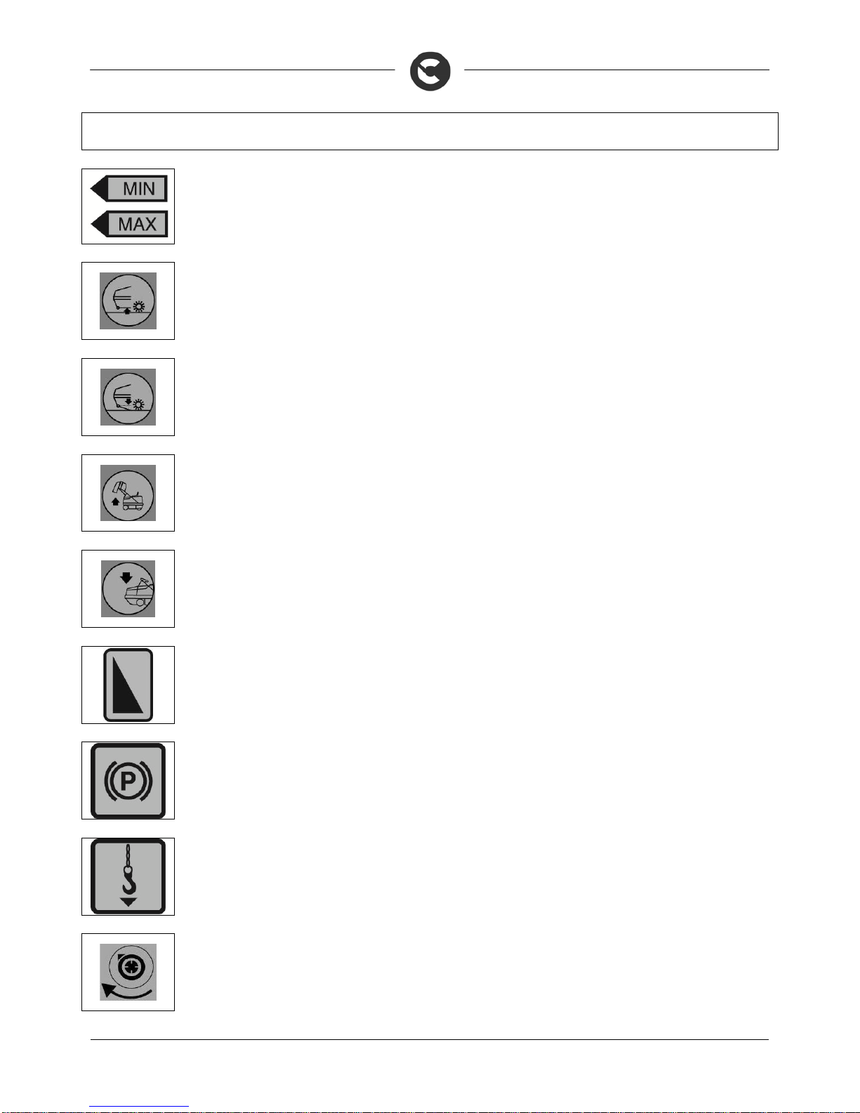
1. HANDLING OF THE PACKED MACHINE
The machine is contained in specific packaging with a pallet for the handling with fork trucks. The
packages cannot be placed on top of each other.
The overall mass of the machine (machine empty and with a side brush) with packaging is:
CS90 B = 810 kg
CS90 D = 870 kg
The dimensions of the packaging is as follows:
CS90
A: 1800 mm
B: 1340 mm
C: 2150 mm
A
C
B
2. HOW TO UNPACK THE MACHINE
1. Remove the outer packaging
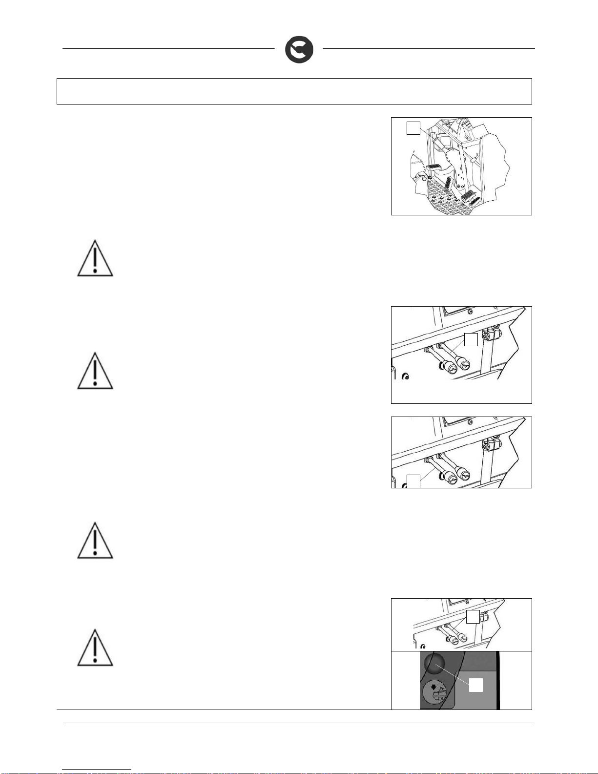
2. The machine is secured to the pallet with wedges that lock the wheels, remove these wedges (1)
3. Disengage the parking brake by turning the lever (2) upwards
4. Check the main machine switch is in the “OFF” position, and if this is not the case, turn it by a quarter
rotation to the left.
5. Turn the knob (3) anticlockwise to release the rotation of the rear cover
6. To access the motor compartment, grip the front part of the rear cover (4)
7. Lift up, rotating the rear cover to its maximum rotation
1
2
3
4

14
MACHINE PREPARATION
8. Rotate the lever (5) on the b
y
-pass valve until it is vertical; this will put the hydraulic system on standby.
9. Lower the rear cover as far as the working position
10. Turn the knob (3) clockwise to block the rotation of the rear cover
11. Use a chute to get the machine down from the pallet, pushing it backwards
12. Keep the pallet for any future transport needs
13. Turn the knob (3) anticlockwise to release the rotation of the rear cover
14. To access the motor compartment, grip the front part of the rear cover (4)
15. Lift up, rotating the rear cover to its maximum rotation
16. Rotate the lever (5) on the b
y
-pass valve until it is horizontal; this will start the hydraulic system working.
17. Lower the rear cover as far as the working position
18. Turn the knob (3) clockwise to block the rotation of the rear cover
WARNING: if the product is delivered in cardboard containers, handle the packed
product with suitable lifting means that comply with the legal requirements
3. HOW TO MOVE THE MACHINE
1. Make sure the debris hopper is empty, otherwise empty it completely
2. Check the central brush is lifted up off the ground
3. Check the side brush(es) is/are lifted up off the ground
4. Place it on a pallet, using a chute
5. Check the main machine switch is in the “OFF” position, and if this is not the case, turn it by a quarter
rotation to the left
6. Engage the parking brake
7. Secure the machine to the pallet using wooden wedges
3
4
5
5

15
MACHINE PREPARATION
4. INSTRUMENT PANEL COMPONENTS (BATTERY VERSION)
The instrument panel components are identified as follows:
1. Vibrating filter shaker control switch
2. Front headlights control switch
3. Total or partial hour meter selector button
4. Horn button
5. Dead man's safety button for lowering the hopper
6. Main key switch
7. Green warning light indicating that the main switch of the machine is active
8. Red warning light indicating low brake oil level (down to reserve)
9. Red warning light indicating that the parking brake is on
10. Green warning light indicating that the machine headlights are on
11. Indicator light for the charge level of the batteries
12. Hour meter display (absolute or partial)
13. Red warning light indicating the oil level of the hydraulic system is low
14. Red warning light indicating the oil filter of the hydraulic system is clogged
15. Red warning light indicating the oil temperature of the hydraulic system is at a critical level
16. Green indicator light showing that the hopper hatch is open
17. Indicator light for the level of the machine's amperage draw
1
2
3
4
5
6
7
8
11 9
10
16 15 17 14 13 12

16
MACHINE PREPARATION
5. INSTRUMENT PANEL COMPONENTS (DIESEL VERSION)
The instrument panel components are identified as follows:
1. Filter shaker control switch
2. Front headlights control switch
3.
A
bsolute or partial hour meter selector button
4. Horn button
5. Dead man's button for lowering the hopper
6. Main key switch
7. Yellow warning light indicating that the fuel level is low
8. Green warning light indicating that the machine headlights are on
9. Red warning light indicating low brake oil level (down to reserve)
10. Red warning light indicating that the parking brake is on
11. Red indicator light indicating that the alternator is not recharging the battery
1
3
4
5
6
2
7
8
10 11
9

17
MACHINE PREPARATION
12. Red warning light indicating the oil level of the hydraulic system is low
13. Red warning light indicating the oil filter of the hydraulic system is clogged
14. Red warning light indicating the oil temperature of the hydraulic system is at a critical level
15. Red indicator light showing that the hopper hatch is closed
16. Green indicator light showing that the hopper hatch is open
17. Yellow indicator light showing that the combustion engine's glow plugs are in the heating phase
18. Red warning light indicating the combustion engine's oil pressure is low
19. Red warning light indicating the air filter of combustion engine is clogged
20. Red warning light indicating the temperature of the combustion engine's coolant is at a critical level
21. Fuel level display
22. Hour meter display (absolute or partial)
23. Rev counter for the combustion engine
24. Combustion engine's coolant temperature display
12
13
14
15
16
17
18
19
20 21
22
24
23

18
MACHINE PREPARATION
6. CONTROL PANEL COMPONENTS (BATTERY VERSION)
The control panel components in the battery version are identified as follows:
1. Central brush control lever
2. Left side brush control lever (optional)
3. Right side brush control lever
4. Control lever for activating and deactivating the vacuum turbine
7. CONTROL PANEL COMPONENTS (DIESEL VERSION)
The control panel components in the diesel version are identified as follows:
1. Central brush control lever
2. Right side brush control lever
3. Left side brush control lever (optional)
4. Control lever for activating and deactivating the vacuum turbine
5. Lever for adjusting the number of revs of the combustion engine
6. Control lever for the hopper hatch
7. Control lever for raising the hopper
8. FOOTBOARD FOOTREST COMPONENTS (BATTERY VERSION)
The components of the footboard are identified as follows:
1. Forward movement pedal
2. Backward movement pedal
3. Brake pedal
4. Parking brake pedal
5. Lever for releasing the parking brake
1
3
4
2
5
6
7
1
2
4
3
2
1
5
4
3

19
MACHINE PREPARATION
6. Battery connector handle
7. Electrical system connector
9. FOOTBOARD FOOTREST COMPONENTS (DIESEL VERSION)
The front components of the footboard are identified as follows:
1. Forward movement pedal
2. Backward movement pedal
3. Brake pedal
4. Parking brake pedal
5. Lever for releasing the parking brake
6. Hydraulic system minimum oil level bulb
7. Hydraulic system maximum oil level bulb
8. Emergency button for starter battery cut-off
10. REAR COVER COMPONENTS
The rear cover components are identified as follows:
1. Seat adjustment lever
2. Handle for raising the cover
3. Cover rotation catch
2
1
5
4
3
6
7
8
1
2
3
7
6

20
MACHINE PREPARATION
4. Blinking light
11. FRONT COVER COMPONENTS
The front cover components are identified as follows:
1. Headlights
2. Handle for raising the cover
12. SIDE COMPONENTS
The front cover components are identified as follows:
1. Side hatch
2. Step for getting on and off
13. TYPE OF BATTERY (BATTERY VERSION)
To power the machine, two 18V battery boxes with nine 2V 480 Ah/5h liquid electrolyte components are
needed. For optimal work performance, DO NOT USE OTHER TYPES. The batteries must meet the
requirements laid out in the norms: CEI EN 60254-1:2005-12 (CEI 21-5) + CEI EN 60254-2:2008-06 (CEI 21-7)
14. TYPE OF STARTER BATTERY (DIESEL VERSION)
As a starter battery, you are advised to use a 12V/55 Ah C5 battery.
To perform well, OTHER TYPES SHOULD NOT BE USED. The battery must meet the requisites indicated
in standards CEI EN 50342, CEI EN 60095-2 and CEI EN 60095-4
4
1
2
1
1
2

21
MACHINE PREPARATION
15. BATTERY MAINTENANCE AND DISPOSAL
For maintenance and recharging, respect the instructions provided by the battery manufacturer.
Particular attention must be paid when choosing the battery charger, if not supplied, since there are
different kinds according to the type and capacity of the battery.
When the battery reaches the end of its working life, it must be disconnected by expert, trained personnel,
then lifted (using the grips and suitable lifting devices) to remove it from the battery compartment.
EXHAUSTED BATTERIES ARE CLASSIFIED AS DANGEROUS WASTE AND MUST BE CONSIGNED
TO THE AUTHORISED BODIES FOR CORRECT DISPOSAL.
WARNING: You are advised to always wear protective gloves, to avoid the risk of
serious injury to your hands.
WARNING: You are advised to only lift and move the batteries with lifting and
transportation means suitable for the specific weight and size
16. MAINTENANCE AND DISPOSAL OF THE COMBUSTION ENGINE
WARNING: For the maintenance and disposal of the combustion engine, observe
the instructions given by the engine manufacturer (for maintenance) and current
environmental hygiene norms (for disposal).
17. HANDLING AND INSERTING THE BATTERIES (BATTERY VERSION)
The batteries must be housed in the special compartment beneath the rear cover. They should be handled
using lifting equipment that is suitable in terms of both weight and coupling system. They must also satisfy
the requirements of Standard CEI 21-5.
WARNING: For battery maintenance and daily recharging, you must fully respect the
indications provided by the manufacturer or retailer. All installation and maintenance
operations must be carried out by specialised personnel.
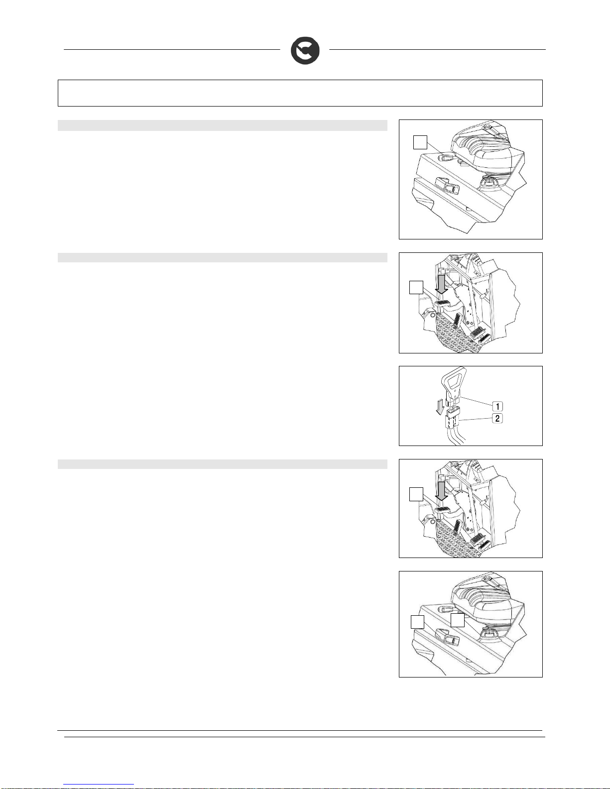
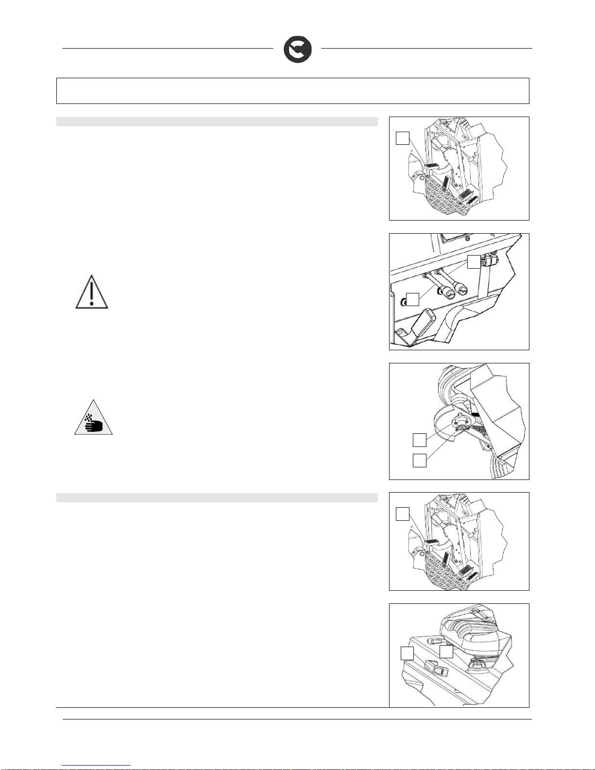
To insert batteries proceed as follows:
1. Block the machine by engaging the parking brake, pressing the pedal (1) down
2. Check the main machine switch is in the “OFF” position, and if this is not the case, turn it by a quarter
rotation to the left
WARNING: you are advised to always wear protective gloves, to avoid the risk of
serious injury to your hands.
3. Turn the cover (2) rotation catch
4. Using the handle (3) turn the rear cover as far as it will go
1
2
3

22
MACHINE PREPARATION
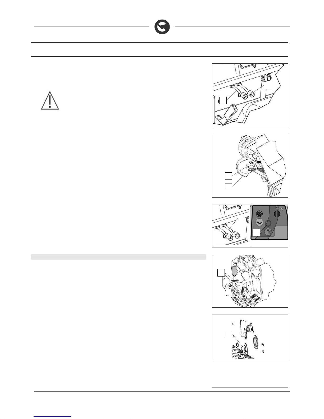
5. Using the right tools remove the screw fixing the cable (4) stopping the rear cover rotating
WARNING: Hold the cord stopping the rear cover rotating firmly during this
operation, otherwise it could rotate too much and get damaged.
6. Turn the rear cover until there is space to get at the battery boxes, rest the cover on a structure to
prevent extra-rotation that could damage the machine
7. Place the batteries inside the battery compartment using transport and handling equipment suitable for
the weight and size of the batteries
8. Place the batteries in the battery compartment with the "+" and "-" poles opposite each other
ATTENTION: You are advised to only lift and move the batteries with lifting and
transportation means suitable for the specific weight and size
18. CONNECTING THE BATTERIES AND BATTERY CONNECTOR (BATTERY VERSION)
1. Connect the batteries in series (1) using the jumper cables supplied, to the “+” and “-“ poles
2. Connect the battery connector cable to the “+” and “-“ poles to obtain a voltage of 36V on the terminals (2)
3. Connect the battery connector cable (2) to the machine connector (3)
4. Connect the 14 V line battery connector cable to the “+” (4) pole to obtain a voltage of 14V on the terminals
WARNING: All installation and maintenance operations must be carried out by
expert personnel, trained at the specialised assistance centre
WARNING: It is recommended that the above-mentioned operations be carried out
by personnel trained by the service centre.
WARNING: You are advised to always wear protective gloves, to avoid the risk of
serious injury to your hands.
19. CONNECTING THE BATTERY CHARGER (BATTERY VERSION)
In order not to cause permanent damage to the batteries, it is essential to avoid their complete discharge:
arrange the recharge within a few minutes of the switching on of the "discharged batteries" blinking light.
ATTENTION: never leave the batteries completely discharged, even if the machine
is not being used. Check the battery charger is suitable for the batteries installed, in
terms of both capacity and type.
To connect the battery charger you must:
1. Move the machine near to the battery charger
2
. Block the machine by engaging the parking brake, pressing the pedal (1) down
3. Check the main machine switch is in the “OFF” position, and if this is not the case, turn it by a quarter
rotation to the left
4
1
1
2
4
3

23
MACHINE PREPARATION
4
. Turn the cover rotation catch (2)
5. Using the handle (3) turn the rear cover as far as it will go
WARNING: you are advised to always wear protective gloves, to avoid the risk of
serious injury to your hands.
6. Gripping the handle (4) disconnect the electrical system connector from the battery connector (5)
7. Connect the battery charger cable connector
The coupling connector of the battery charger is consigned inside the bag containing this instruction
booklet, and must be assembled on the cables of the battery charger as indicated in the instructions.
ATTENTION: This process must be carried out by qualified personnel. An incorrect
connection of the connector may cause problems with machine functioning.
8. Connect the recently wired cable to the external battery charger
9. After the charging cycle is complete, the battery connector must be connected to the electrical system connector
WARNING: Make sure that the battery charger that is to be used is suitable for the
batteries in the machine.
WARNING: Carefully read the use and maintenance instructions of the battery
charger that is used for charging.
WARNING: Keep the seat mounting plate raised for the whole duration of the battery
recharging cycle to allow gas fumes to escape
ATTENTION: danger of exhalation of gas and leakage of corrosive liquids.
ATTENTION: danger of fire: do not go near with free flames
2
3
4 5
24
MACHINE PREPARATION
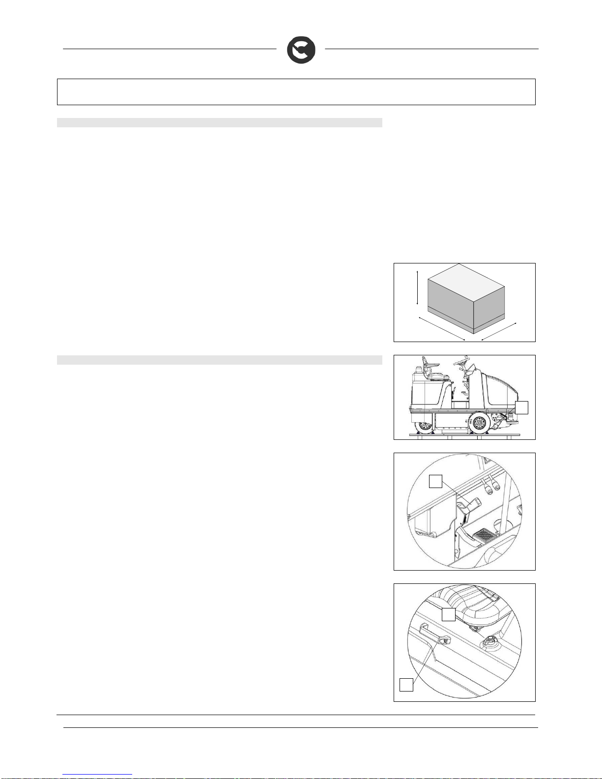
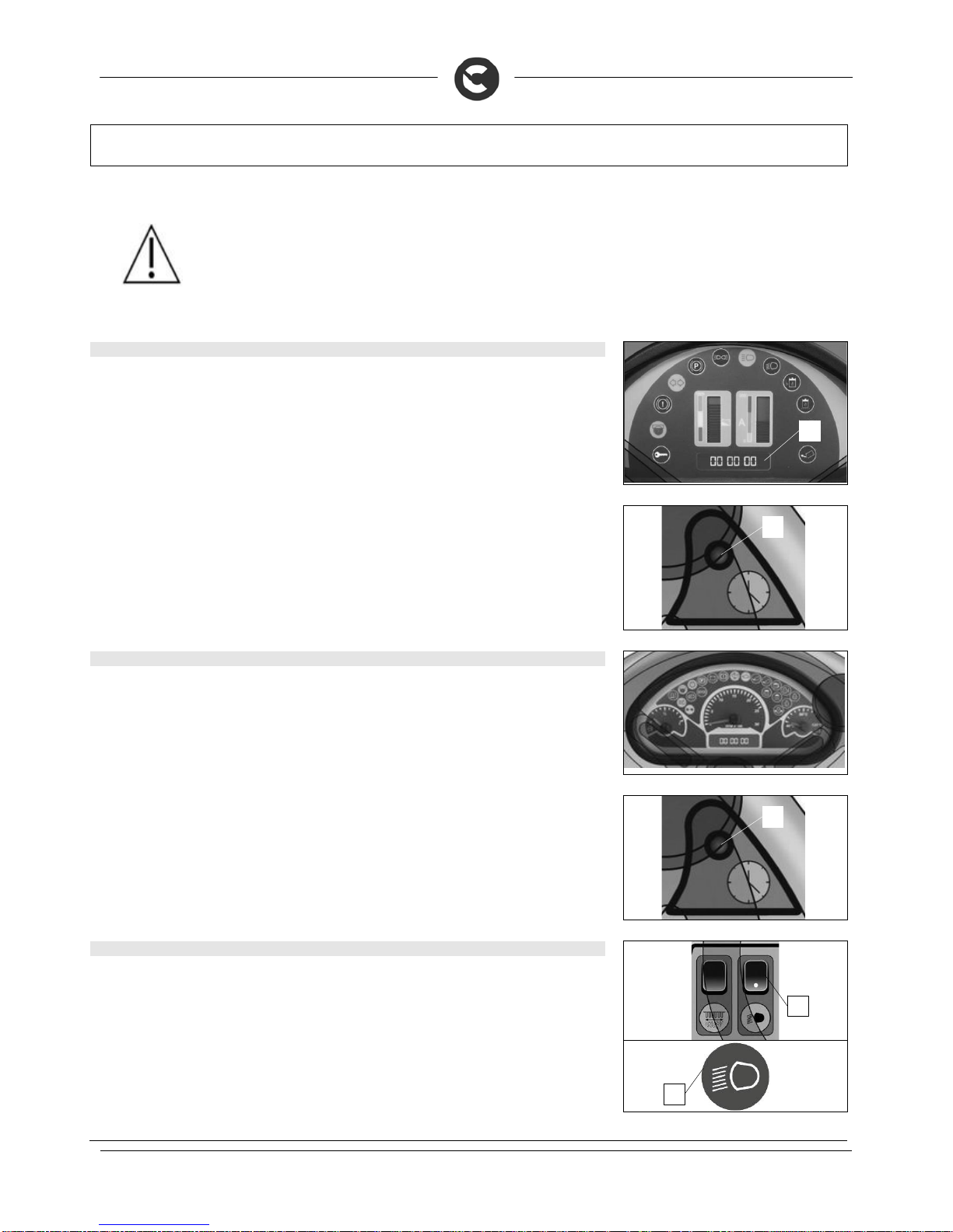
20. BATTERY CHARGE LEVEL INDICATOR (BATTERY VERSION)
On the instrument panel of the machine there is a monitor (1) indicating (amongst other things) the battery
charge status. If the led lights reach a watch level (red colour), the battery charging is critical and an
intermittent buzzer will go off.
21. FILLING THE FUEL TANK (DIESEL VERSION)
The machine is supplied without any fuel in the tank of the combustion engine. To fill the tank, proceed as
follows:
1. Block the machine by engaging the parking brake, pressing the pedal (1) down
2
. Check the main machine switch is in the “OFF” position, and if this is not the case, turn it by a quarter
rotation to the left
3. Turn the cover rotation catch (2)
4
. Using the handle (3) rotate the rear cover as far as it will go
5. Unscrew the cap (4) of the fuel tank and fill it up to the top.
WARNING: Diesel is highly inflammable and can explode.
WARNING: Fill up the fuel tank in a well-ventilated area and with the machine off.
Do not smoke or take any unprotected flames or sparks near the motor while it is
being filled, or in the area where the gasoline is stored.
WARNING: during the filling operation, be careful not to spill the fuel. Spilt fuel or
fuel vapours could ignite. If any fuel is accidentally spilt, remove it thoroughly
before switching on the motor.
1
1
2
3
4
25
MACHINE PREPARATION
22. FUEL LEVEL INDICATOR (DIESEL VERSION)
On the instrument panel of the machine there is a display (1) indicating the level of the fuel tank. If the
yellow led comes on (2) it means that the tank is running extremely low and needs filling up.
23. CHECKING THE OIL LEVEL OF THE COMBUSTION ENGINE
Before checking the level of oil in the combustion engine, do as follows:
1. Block the machine by engaging the parking brake, pressing the pedal (1) down
2
. Check the main machine switch is in the “OFF” position, and if this is not the case, turn it by a quarter
rotation to the left
3. Turn the cover rotation catch (2)
4
. Using the handle (3) rotate the rear cover as far as it will go
5. Follow the procedures set out in the combustion engine's use and
maintenance manual
WARNING: Always check the motor before using it (and read the relevant use and
maintenance manual). In this way, you will avoid any accidents or damage to the motor.
24. CHECKING THE COMBUSTION ENGINE'S AIR FILTER
Before checking the condition of the combustion engine's air filter, do as follows:
1. Block the machine by engaging the parking brake, pressing the pedal (1) down
2
. Check the main machine switch is in the “OFF” position, and if this is not the case, turn it by a quarter
rotation to the left
3. Turn the cover rotation catch (2)
4
. Using the handle (3) rotate the rear cover as far as it will go
1
2
1
2
3
1
2
3
26
MACHINE PREPARATION
5. Follow the procedures set out in the combustion engine's use and maintenance manual
WARNING: Always check the motor before using it (and read the relevant use and
maintenance manual). In this way, you will avoid any accidents or damage to the motor.
25. HOUR METER (BATTERY VERSION)
On the instrument panel of the machine there is a display (1) indicating the total number of working hours,
or by pressing the button (2) the partial hours are displayed. The total number of hours display is divided
into three pairs of numbers that identify the effective work hours that have passed.
The partial number of hours display is divided into three pairs of numbers, the first four identify the hours
that have passed, while the last two numbers identify the tenths of an hour that have passed.
The flashing hourglass symbol indicates that the hour meter is counting the time the machine is operating.
26. HOUR METER (DIESEL VERSION)
On the instrument panel of the machine there is a display (1) indicating the total number of working hours,
or by pressing the button (2) the partial hours are displayed. The total number of hours display is divided
into three pairs of numbers that identify the effective work hours that have passed.
The partial number of hours display is divided into three pairs of numbers, the first four identify the hours
that have passed, while the last two numbers identify the tenths of an hour that have passed.
The flashing hourglass symbol indicates that the hour meter is counting the time the machine is operating.
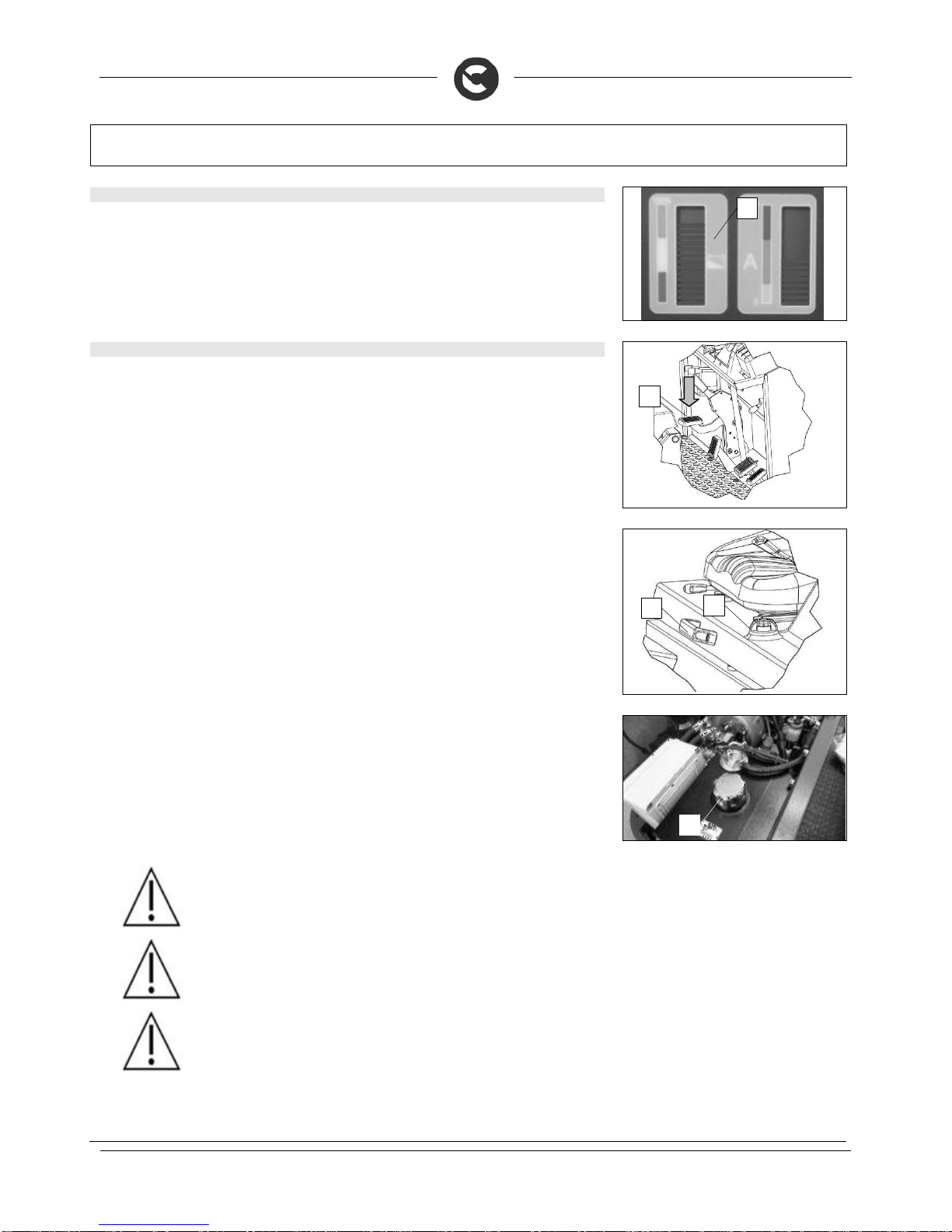
27. TURNING LIGHTS ON/OFF
The machine is equipped with two front headlights, to help the operator to work in low light. To switch on
the headlights simply turn the switch (1) located on the instrument panel to the "I" position and the green
indicator light (2) on the instrument panel will immediately illuminate; the lights will remain on until you
again operate the switch.
1
2
2
2
1

27
MACHINE PREPARATION
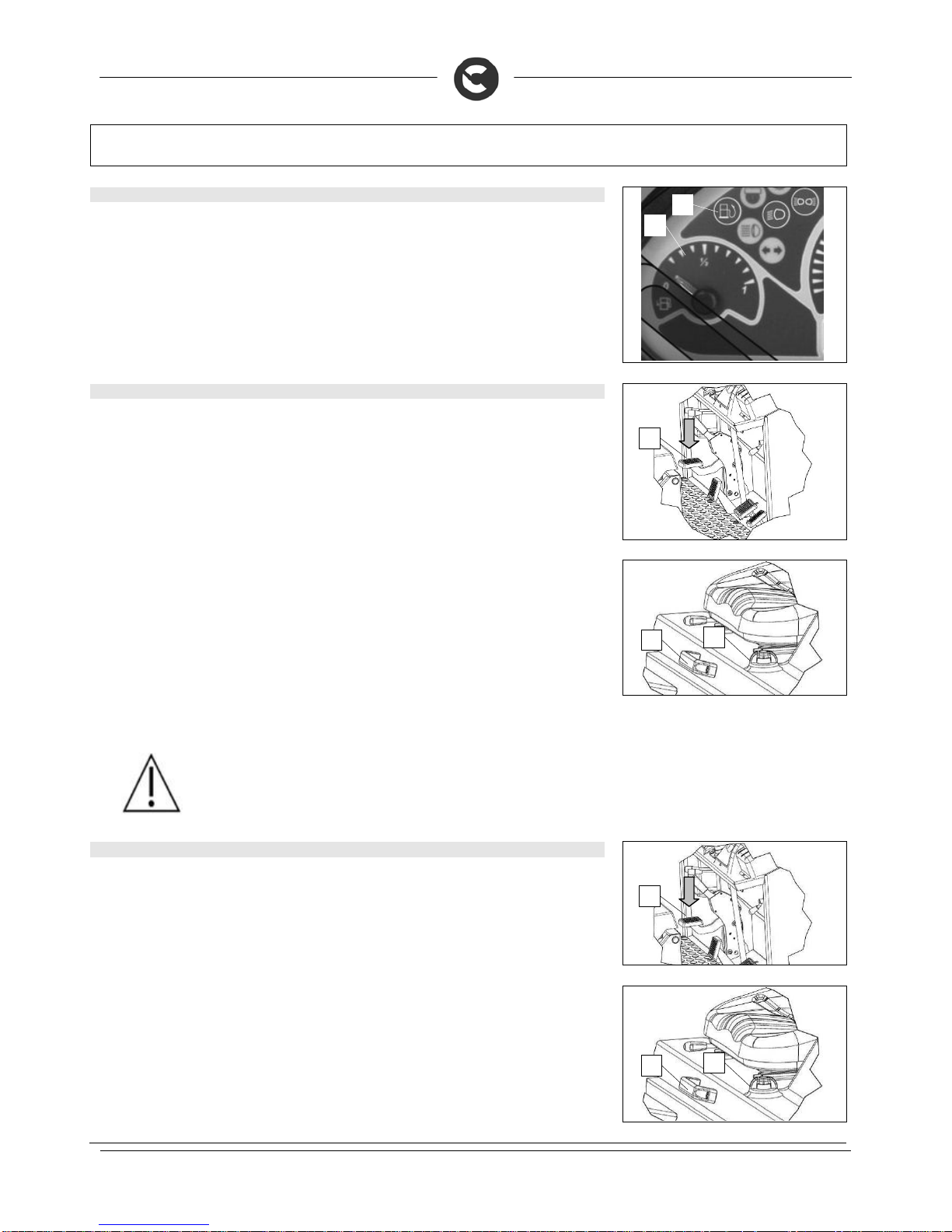
28. SERVICE BRAKE – PARKING BRAKE
The machine has a mechanical braking system, in normal conditions just press the pedal (1) down.
In case of lack of oil in the braking system, the red warning light (2) on the instrument panel will come on;
check the level in the brake oil tank located behind the vehicle nose.
To engage the parking brake press the pedal (3) down, the red warning light (4) on the instrument panel
will come on. To disengage the parking brake, use the lever (5).
29. WORKING FORWARD SPEED
To move the machine in the work direction, turn the key to “ON - I” then press the pedal (1) down, adjusting
the speed by altering the degree of pressure on the pedal. To go in reverse, press the pedal (2) down.
WARNING! The reverse speed is lower than the forward speed to comply with
current health and safety standards.
30. SIDE BRUSH ASSEMBLY
To assemble the side brush, proceed as follows:
1. Check that the side brush is raised off the ground, if not use the lever (1) on the control panel (for the
left side brush), while using the lever (2) on the control panel (for the right side brush)
2. Engage the parking brake located on the left side of the machine
1
4
2
3
5 2 1 2
1
28
MACHINE PREPARATION
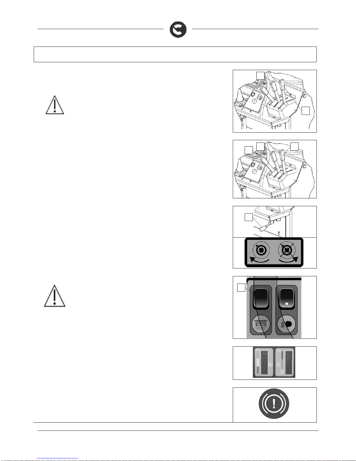
3. Make sure that the main switch is in the "ON" position, if not turn it by a quarter rotation to the right
4. Make sure that the hopper hatch is closed, if this is not the case not pull the lever (4) upwards
5. Raise the hopper to its maximum height, pulling the lever (3) up, engage the safety catches supplied
with the machine
ATTENTION! The safety catches, supplied with the machine, should be inserted
into the shafts of the pistons controlling the raising of the hopper.
6. Check the main machine switch is in the “OFF” position, and if this is not the case, turn it by a quarter
rotation to the left
7. With the proper equipment, remove the screws (5) in the side brush hub
8. Insert the side brush into the brush hub (6)
9. With the proper equipment, fix the side brush to the brush hub (6) using the screws (5)
10. Remove the safety catches
11. Make sure that the main switch is in the "ON" position, if not turn it by a quarter rotation to the right
12. Lower the hopper until it is in the work position, pulling the lever (3) downwards, while at the same
time pushing the dead man's button (7) on the instrument panel
31. CHECKING THE HYDRAULIC SYSTEM OIL
This machine is equipped with a hydraulic system. To ensure optimum machine performance, check the oil
level in the following way:
1. Block the machine by engaging the parking brake, pressing the pedal (1) down
2
. Check the main machine switch is in the “OFF” position, and if this is not the case, turn it by a quarter
rotation to the left
3. Check the oil is not below the minimum level, as seen on the transparent cap (2). If necessary, add
more oil by following the instructions in the “MAINTAINING THE HYDRAULIC OIL LEVEL” chapter.
3
4
1
2
3
7
6
5

29
MACHINE PREPARATION
32. SAFETY BELT INSERTION (OPTIONAL)
The machine can be equipped with a lap belt safety device which allows the operator to be anchored to
the driving seat.
To fasten the safety belt proceed as follows:
1. position yourself on the driving seat
2. take hold of the mobile part (1) of the safety belt
3. wrap it around the abdominal area
4. insert the mobile part (1) into the slot on the fixed part (2)
5. release the belt to allow the seatbelt tensioner to roll the belt back up
To uncouple the safety belt press the button (3) and remove the mobile part (1) or push the rapid
uncoupling button (4)
1
3
2
4
30
PREPARING TO WORK
33. SEAT ADJUSTMENT
The adjustment of the driver's seat is very important for ensuring a comfortable position for the operator,
and to do this proceed as follows:
1. sit on the driver’s seat
2
. Use the lever (1), move the seat backwards or forwards until the most suitable position has been found
34. PREPARING THE BATTERY VERSION OF THE MACHINE TO WORK
Before beginning to work, it is necessary to:
1. Block the machine by engaging the parking brake, pressing the pedal (1) down
2
. Check the main machine switch is in the “OFF” position, and if this is not the case, turn it by a quarter
rotation to the left
3. Connect the battery connector (1) to the electric system connector (2)
35. PREPARING THE DIESEL VERSION OF THE MACHINE TO WORK
Before beginning to work, it is necessary to:
1. Block the machine by engaging the parking brake, pressing the pedal (1) down
2
. Check the main machine switch is in the “OFF” position, and if this is not the case, turn it by a quarter
rotation to the left
3. Turn the cover rotation catch (2)
4
. Using the handle (3) rotate the rear cover as far as it will go
1
1
1
2
3

31
PREPARING TO WORK
5. Check that the level of the radiator coolant is between the "MAX" notch and the "MIN" notch, and if
necessary follow the instructions in the section "FILLING THE COMBUSTION ENGINE'S COOLANT
TANK (DIESEL VERSION)"
WARNING: Check the level of the combustion engine's cooling system fluid with the
engine off, with the engine at ambient temperature, with the machine parked on a flat
surface.
6. Check that the cyclone filter is clean, if necessary follow the instructions in the section "CLEANING
THE COMBUSTION ENGINE'S CYCLONE PREFILTER (DIESEL VERSION)"
7. Check that the radiator is clean, if necessary follow the instructions in the section "CLEANING THE
COMBUSTION ENGINE'S RADIATOR (DIESEL VERSION)"
8. Check that the fuel tank is clean, if necessary follow the instructions in the section "FILLING THE
FUEL TANK (DIESEL VERSION)"

32
WORK
36. SWITCHING ON THE MACHINE, DIESEL VERSION
1. sit on the driver’s seat
ATTENTION! The machine is fitted with a dead man's micro-switch beneath the seat;
this prevents the machine from moving if the operator is not correctly seated
2
. Check that the accelerator lever (1) is at the minimum, if not pull it upwards
3. Turn the key of the main switch a quarter of a turn clockwise (to position 1). Immediately, on the
instrument panel, the display (4) will turn on indicating the level of fuel in the diesel tank
4
. Check the parking brake is released, if not use the lever (2), the warning light (3) on the instrument
panel will go out
5. Wait for the yellow led of the glow plugs to go out, then bring the motor ignition switch to the "START"
position (turning the key further to the right), and keep it there until the motor starts. When the engine
starts, release the key
T
o ensure the machine works correctly, a few seconds after the combustion engine starts bringing the lever
(1) to its limit, in this way the accelerator will be at its maximum stroke.
WARNING: Do not use the starter for more than 5 seconds at a time. If the motor does
not start up, release the key and wait for 10 seconds before making a new attempt.
37. SWITCHING ON THE MACHINE, BATTERY VERSION
1. sit on the driver’s seat
ATTENTION! The machine is fitted with a dead man's micro-switch beneath the seat;
this prevents the machine from moving if the operator is not correctly seated
2
. Turn the key of the main switch a quarter of a turn clockwise (to position 1). Immediately, on the
instrument panel, the display (3) will turn on indicating the charge level of the batteries, and also the
display (4), indicating the machine's amperage draw
3. Check the parking brake is released, if not use the lever (1), the warning light (2) on the instrument
panel will go out
1
2
3
4
1
1
2
3
4

33
WORK
The display (3) shows the state of the charge of the batteries, when the batteries supplied with the
machine are full the column composed of luminous notches arrives at the green zone of the scale printed
on the instrument panel. As the batteries gradually run down, the notches go out and, with the batteries
completely run down (red zone), the notches start to flash and an intermittent buzzer starts to sound. The
flashing hourglass symbol indicates that the hour meter is counting the time the machine is operating.
38. STARTING TO WORK
T
o start working, do as follows:
1. Open the hopper hatch, pulling the lever (1) down. As soon as the debris hopper hatch is open, the
indicator light (2) on the instrument panel will come on.
ATTENTION! If along the machine's path there are large pieces of waste, shut the
hatch temporarily to allow the central brush to access and collect it
2. Lower the central brush, using the lever (3) on the control panel
WARNING: The central brush will start to rotate as soon as it reaches its work position.
3. Start the vacuum, turn the lever (4) left
ATTENTION! When working on a wet area or if wet dirt is being collected, the
vacuum motor should be switched off by turning the lever (6) to the right, and once
the critical zone has passed the vacuum motor can be started again.
4. Press the accelerator pedal (5) to start moving the machine
ATTENTION: Adjust the working speed according to the amount of waste and
debris to be collected
To make a reverse manoeuvre, push the accelerator pedal (6) downwards, the machine will begin to
move backwards.
WARNING! The reverse speed is lower than the forward speed to comply with
current health and safety standards.
3
4
1
2
5
6
34
WORK
If the dirt level requires it, lower the right side brush, (1SL versions) using the lever (7) on the control
panel. If you want to lower the optional left brush (2SL versions), use the lever (8)
ATTENTION: Use the side brush or brushes (according to machine version) only
on edges, as it is not assisted by the vacuum action.
WARNING: Both the central brush and the side brush will begin rotating as soon as
they are in their work position.
In order to achieve a correct vacuum action, clean the filter every 10 minutes and always before any
discharge of the debris hopper. To do this, proceed as follows:
1. Stop the machine and engage the parking brake
2. Raise the central brush, using the lever (1) on the control panel
3. Raise the side brush or the side brushes if lowered, using the lever (2) for the right brush and the lever
(3) for the left brush on the control panel
4. Switch off the vacuum, turn the lever (4) to the right
5.
A
ctivate the filter shaker on the filter by pressing the switch (5) on the control panel
Periodically check the filling of the tray and if necessary proceed to empty it. Bear in mind that the weight
of the dirt collected is proportional to the specific weight of the material brushed up. In the case of heavy
material such as sand, soil, gravel, etc. the tray should ideally not be filled more than 70%, otherwise it
may be difficult to empty
ATTENTION! Do not keep the switch (5) pressed longer than ten seconds, repeat
this operation two or three times.
If during the work the amperage draw (only for the battery versions) reaches a critical level, the machine
should be stopped. The machine is fitted with display for diagnosing system anomalies and checking the
electrical motor. Once a critical threshold has been reached, a horn will activate in this case, it is
necessary to stop, park the machine in a suitable place and call for assistance.
If during the work the red warning light shown here on the side on the instrument panel comes on, it
indicates that the level of oil in the braking system is "poor", you need to stop the work you are doing and
take the machine to a suitable place for its maintenance and call for assistance.
8
7
1
3 2
4
5

35
WORK
If during the work the red warning light shown here on the side on the instrument panel comes on, it
indicates that the level of oil in the hydraulic system is "poor", you need to stop the work you are doing
and take the machine to a suitable place for its maintenance and call for assistance.
If during the work the red warning light shown here on the side on the instrument panel comes on, it
indicates that the oil filter of the hydraulic system is clogged, you need to stop the work you are doing and
take the machine to a suitable place for its maintenance and call for assistance.
If during the work the red warning light shown here on the side on the instrument panel comes on, it
indicates that the oil in the hydraulic system reached a critical temperature, you need to stop the work you
are doing and take the machine to a suitable place for its maintenance and call for assistance.
If during the work the red warning light shown here on the side on the instrument panel comes on, it
indicates that there is a fault with the alternator (diesel version), you need to stop the work you are doing
and take the machine to a suitable place for its maintenance and call for assistance.
If during the work the red warning light shown here on the side on the instrument panel comes on, it
indicates that the air filter of the combustion engine is clogged (diesel version), you need to stop the work
you are doing and take the machine to a suitable place for its maintenance and call for assistance.
If during the work the red warning light shown here on the side on the instrument panel comes on, it indicates
that there is a fault with the oil pressure of the combustion engine (diesel version), you need to stop the work
you are doing and take the machine to a suitable place for its maintenance and call for assistance.
If during the work the fuel level displayed on the instrument panel reaches a critical zone the yellow
indicator light comes on, indicating that the diesel fuel is running on reserves (diesel version) you need to
stop the work you are doing and take the machine to a suitable place for its maintenance and fill up the
fuel tank, following the instructions in the chapter "FILLING THE FUEL TANK (DIESEL VERSION)"

36
AT THE END OF THE WORK
39. AT THE END OF THE WORK
A
t the end of the work, do as follows:
1. Stop the machine and engage the parking brake, pressing the pedal (1)
2
. Raise the central brush from the ground, using the lever (2)
3. Raise the right side brush from the ground, using the lever (3)
4
. Raise the left side brush from the ground (if present as an optional), using the lever (4)
5. Close the hopper hatch, pulling the lever (5) upwards. As soon as the debris hopper hatch is closed,
the indicator light (6) on the instrument panel will go out.
6. Switch off the vacuum, turn the lever (7) to the right
7.
A
ctivate the filter shaker on the filter by pressing the switch (8) on the control panel
ATTENTION! Do not keep the switch (5) pressed longer than ten seconds, repeat
this operation two or three times.
2
4 3
1
5
6
8
7
37
AT THE END OF THE WORK
8. Disengage the parking brake by means of the lever (9)
9. Bring the machine close to the waste unloading zone, stop it and engage the parking brake
WARNING! Calculate the distance between the machine and the waste container
correctly, bearing in mind the rotation radius of the debris hopper when moving.
10. Raise the hopper to the desired height, pull the lever (10) upwards.
11. Disengage the parking brake
12. Bring the machine close to the waste container, so that the debris hopper is inside the hopper's refill
opening
WARNING! Reduce the machine's movement speed when the debris hopper is
lifted off the ground.
WARNING! Avoid unloading the debris while the machine is sloped.
WARNING! Do not activate the filter shaker while the debris hopper is lifted off the
ground.
13. Engage the parking brake
14. Slowly open the hopper hatch, pulling the lever (5) upwards. As soon as the debris hopper is open, the
refuse will start to come out.
15. Once the refuse has come out, close the hopper hatch, pulling the lever (5) downwards.
16. Disengage the parking brake
17. Remove the machine from the waste unloading zone, stop the machine and engage the parking brake
WARNING! Reduce the machine's movement speed when the debris hopper is
lifted off the ground.
WARNING! Calculate the distance between the machine and the waste container
correctly, bearing in mind the rotation radius of the debris hopper when moving.
18. Engage the parking brake
19. Lower the hopper, bringing it to a work position, pulling the lever (10) downwards.
ATTENTION! The hopper will not move until the dead man's button (11) on the
instrument panel is pressed
9
10
5
10
11

38
AT THE END OF THE WORK
2
0. Disengage the parking brake
2
1. Take the machine to the designated machine storage place.
2
2. Engage the parking brake.
2
3. Bring the main machine switch to "OFF-0" by turning the key a quarter rotation to the left.
WARNING! Park the machine in a closed place, on a flat and level surface, where
it cannot cause harm to people or damage to other property, but also be protected
from any accidental fall of objects.
ATTENTION! For the diesel and Bifuel versions, avoid parking the machine near
sources of heat.
For the "battery" version, proceed as follows:
1. Disconnect the electrical system connector (1) from the battery connector (2)
For the "diesel" version, proceed as follows:
1. Position the accelerator lever (1) at the minimum, pulling it up
1

39
DAILY MAINTENANCE
PERFORM ALL MAINTENANCE OPERATIONS IN SEQUENCE
40. CLEANING THE CENTRAL BRUSH
Proceed as follows in order to clean the central brush:
1. Engage the parking brake, pressing the pedal (1)
2. Check the main machine switch is in the “OFF-0” position. If this is not the case, turn the key by a
quarter rotation to the left.
3. Turn the knob (2) anticlockwise and open the right hatch (3)
ATTENTION: This operation must be carried out using gloves to protect
against contact with dangerous substances.
4. Release the hinge (4) fixing the articulated arm (5) of the central brush
5. Withdraw the articulated arm (5) of the central brush from the central brush control arm (6)
ATTENTION: This operation must be carried out using gloves to protect
against contact with dangerous substances.
6. Withdraw the articulated arm (5) of the central brush from the central brush (7)
7. Remove the central brush (7) from the machine
8. Clean it under a jet of running water and remove any residue
ATTENTION: This operation must be carried out using gloves to protect
against contact with dangerous substances.
9. Reassemble all the elements.
ATTENTION: The brush is correctly fitted when, seen from above, the cusp
forms an upturned “V” (refer to the picture)
1
2
3
4
5
6
7
40
DAILY MAINTENANCE
41. CLEANING THE SIDE BRUSH
Proceed as follows in order to clean the side brush:
1. Engage the parking brake, pressing the pedal (1)
2
. sit on the driver’s seat
3. Turn the main machine switch to "ON-1" by turning the key a quarter rotation to the right
4
. Make sure that the hopper hatch is closed, if this is not the case not pull the lever (2) upwards
5. Raise the hopper to its maximum height, pulling the lever (3) up, engage the safety catches supplied
with the machine
ATTENTION! The safety catches, supplied with the machine, should be inserted
into the shafts of the pistons controlling the raising of the hopper.
6. Turn the main machine switch to "OFF-0" by turning the key a quarter rotation to the left
7. With the proper equipment, remove the screws (5) in the side brush hub
8. Remove the side brush from the machine
WARNING: This operation must be carried out using gloves to protect against
contact with dangerous solutions.
9. Clean it under a jet of running water and remove any residue
42. CLEANING OF THE DIESEL MOTOR'S CYCLONE PREFILTER
Proceed as follows in order to clean the cyclone filter:
1. Engage the parking brake, pressing the pedal (1)
2
. Check the main machine switch is in the “OFF-0” position. If this is not the case, turn the key by a
quarter rotation to the left.
3. Turn the cover rotation catch (2)
4
. Using the handle (3) rotate the rear cover as far as it will go
1
3
2
5
4
1
2
3

41
DAILY MAINTENANCE
5. Remove the cover (4) of the cyclone filter, turning the knob (5) anti-clockwise
WARNING: This operation must be carried out using gloves to protect against
contact with dangerous solutions.
6. Remove the cyclone filter (6) and clean it with a cloth
43. CLEANING THE DIESEL MOTOR'S RADIATOR
Proceed as follows in order to clean the radiator:
1. Engage the parking brake, pressing the pedal (1)
2
. Check the main machine switch is in the “OFF-0” position. If this is not the case, turn the key by a
quarter rotation to the left.
3. Turn the cover rotation catch (2)
4
. Using the handle (3) rotate the rear cover as far as it will go
WARNING: This operation must be carried out using gloves to protect against
contact with dangerous solutions.
5. Using the right tools remove the screw fixing the cable (4) stopping the rear cover rotating
WARNING: During this operation hold onto the cord for stopping the cover
rotating, otherwise it could start twisting and get damaged.
6. Turn the rear cover until the radiator's air passage can be accessed
5
4
6
1
2
3
4
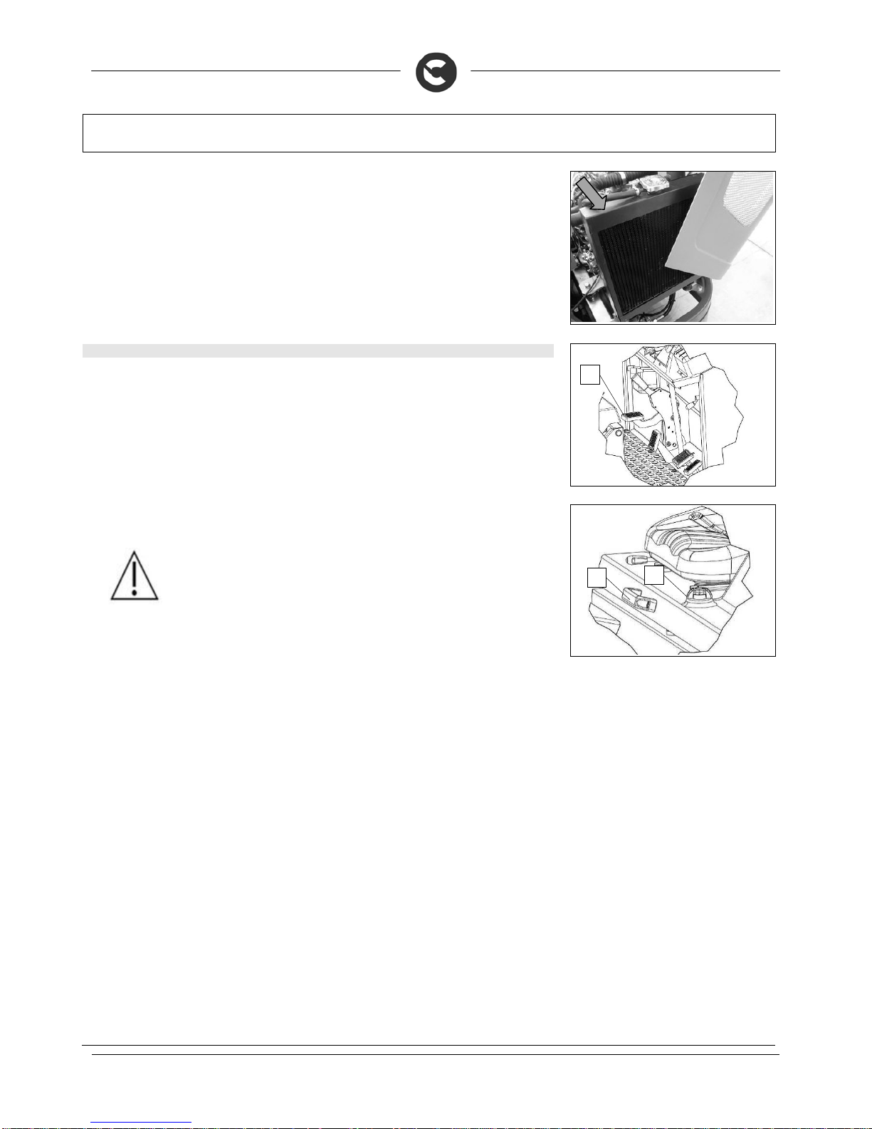
42
DAILY MAINTENANCE
7. Use a jet of compressed air to clean the radiator, from the inside to the outside of the machine.
44. MAINTENANCE OF THE COMBUSTION ENGINE
Proceed as follows in order to carry out maintenance of the combustion engine:
1. Engage the parking brake, pressing the pedal (1)
2
. Check the main machine switch is in the “OFF-0” position. If this is not the case, turn the key by a
quarter rotation to the left.
3. Turn the cover rotation catch (2)
4
. Using the handle (3) rotate the rear cover as far as it will go
WARNING: Read the combustion engine's use and maintenance manual,
supplied with the machine, carry out the daily maintenance set out in it.
1
2
3

43
WEEKLY MAINTENANCE
45. CLEANING THE VACUUM FILTER
Whenever the vacuum action seems to be unsatisfactory, check that the vacuum filter is not obstructed. If
necessary clean with an air jet as follows:
1. Engage the parking brake, pressing the pedal (1)
2
. Check the main machine switch is in the “OFF-0” position. If this is not the case, turn the key by a
quarter rotation to the left.
3. Remove the rotation lock of the front cover
4
. Using the slot (2) turn the front cover as far as it will go
WARNING: This operation must be carried out using gloves to protect against
contact with dangerous solutions.
5. Block the rotation of the front cover, insert the pin (3) into the slot (4)
6. Remove the vacuum cover, releasing it from its catches (5).
7. Place it on the ground, move it using its handles (6)
8. Remove the fabric filter, make sure to disconnect it from the machine's electrical system
9. Place it on something that is suitable for its weight and size
10. Clean the panel filter with a vacuum cleaner
11. Reassemble all the elements
WARNING: The fabric filter should not be put on the ground so as not to dirty it
further.
WARNING: It is recommended that the electrical connection operations be carried
out by personnel trained by the service centre.
1
2
3
4
5
6

44
WEEKLY MAINTENANCE
46. CLEANING THE DEBRIS HOPPER
Clean the debris hopper every week as follows:
1. Take the machine to the area used for discharging sewage
2
. Engage the parking brake, pressing the pedal (1)
3. Open the hopper hatch, moving the lever (2) down
4
. Bring the main machine switch to "OFF-0" by turning the key a quarter rotation to the left.
ATTENTION! The safety catches, supplied with the machine, should be inserted
into the shafts of the pistons controlling the raising of the hopper.
5. Remove the rotation catch of the front cover
6. Using the slot (3) turn the front cover as far as it will go
WARNING: This operation must be carried out using gloves to protect against
contact with dangerous solutions.
7. Block the rotation of the front cover, insert the pin (4) into the slot (5)
8. Remove the vacuum cover, releasing it from its catches (6).
9. Place it on the ground, move it using its handles (7)
1
2
3
4
5
6
7

45
WEEKLY MAINTENANCE
10. Remove the fabric filter, make sure to disconnect it from the machine's electrical system
11. Place it on something that is suitable for its weight and size
WARNING: The fabric filter should not be put on the ground so that it does not get
dirty.
12. Rinse the inside of the hopper with a jet of running water
ATTENTION: This operation must be carried out using gloves to protect against
contact with dangerous substances.
13. Reassemble all the elements
WARNING: It is recommended that the electrical connection operations be carried
out by personnel trained by the service centre.
47. CENTRAL BRUSH ADJUSTMENT
If the side brush does not channel the dirt effectively towards the debris hopper, you must adjust its height
in relation to the ground. Proceed as follows:
1. Engage the parking brake, pressing the pedal (1)
2
. Check the main machine switch is in the “OFF-0” position. If this is not the case, turn the key by a
quarter rotation to the left.
3. Lower the central brush to the ground, using the lever (2)
4
. Raise the right side brush from the ground, using the lever (3)
5. Raise the left side brush from the ground (if present as an optional), using the lever (4)
6. Turn the knob (5) anticlockwise and open the right hatch
1
5
2
4 3
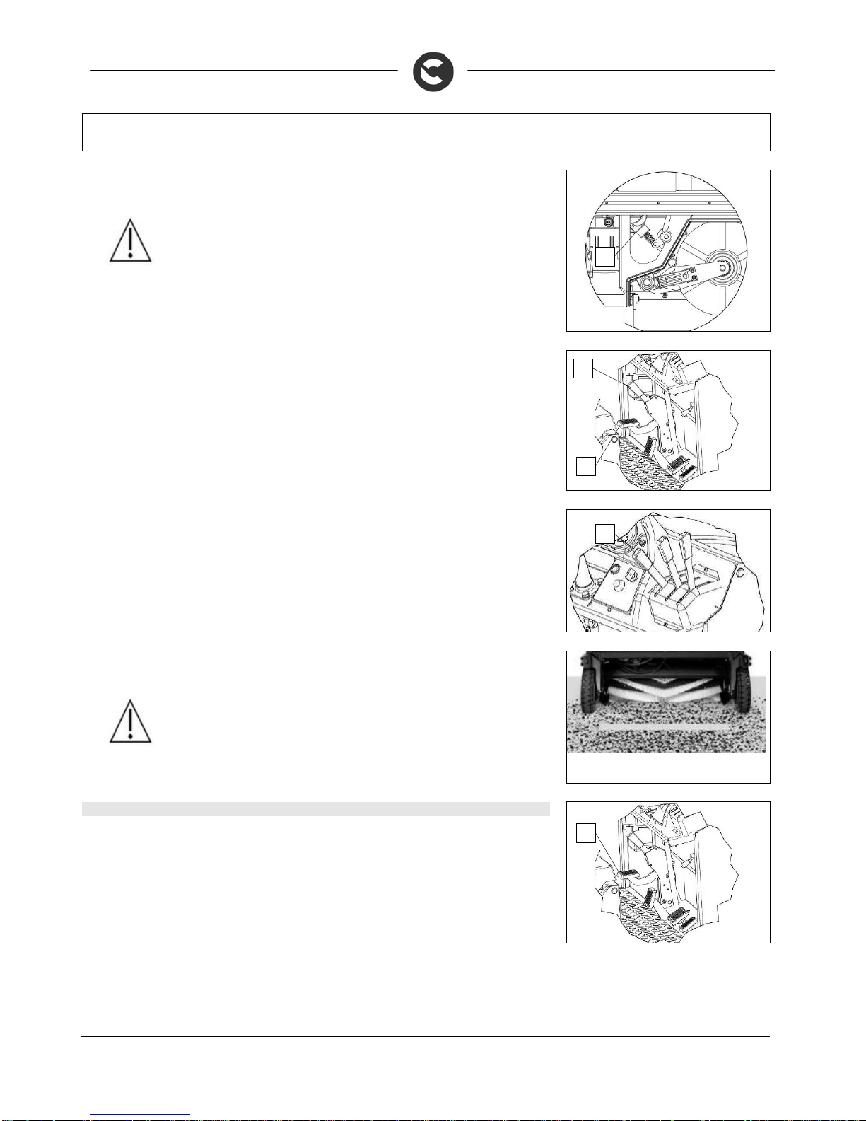
46
WEEKLY MAINTENANCE
7. To increase or lower the height of the brush off the ground, use the knob (3)
8. Reassemble all the elements
WARNING: The correct adjustment of the central brush should bring about a work
footprint no wider than a few centimetres
To check that the work footprint is correct, do as follows:
1. Park the machine on flat ground
2. Engage the parking brake, pressing the pedal (1)
3. Starting the machine
4. Lower the central brush to the ground, using the lever (2), let it work for a few seconds
5. Raise the central brush from the ground, using the lever (2)
6. Release the parking brake with the lever, using the lever (3)
7. Move the machine the distance needed for showing the footprint of the work track
WARNING: If the footprint does not meet the desired characteristics, repeat the
adjustment
48. SIDE BRUSH ADJUSTMENT
If the side brush does not channel the dirt effectively towards the centre of the machine, you must adjust its
height in relation to the ground. Proceed as follows:
1. Engage the parking brake, pressing the pedal (1)
2
. Check the main machine switch is in the “OFF-0” position. If this is not the case, turn the key by a
quarter rotation to the left.
3
1
1
2
3
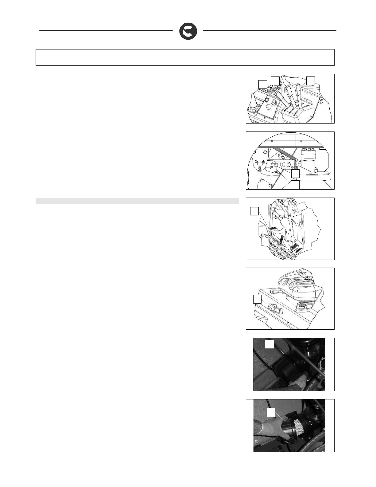
47
WEEKLY MAINTENANCE
3. Raise the central brush from the ground, using the lever (2)
4
. Lower the central brush to the ground, using the lever (3)
5. Raise the left side brush from the ground (if present as an optional), using the lever (4)
6. By using the right equipment, loosen the counter nut (5) and the adjustment screw (6)
7. Adjust the screw (6) so that the front half of the side brush rests on the ground when operating.
49. CLEANING THE DIESEL ENGINE'S AIR FILTER
Proceed as follows in order to clean the cyclone filter:
1. Engage the parking brake, pressing the pedal (1)
2
. Check the main machine switch is in the “OFF-0” position. If this is not the case, turn the key by a
quarter rotation to the left.
3. Turn the cover rotation catch (2)
4
. Using the handle (3) rotate the rear cover as far as it will go
5. Remove the catches (4) that fix the filter cover to the filter body
6. Remove the cover (5) from the filter body
2
4 3
5
6
1
2
3
4
5

48
WEEKLY MAINTENANCE
7. Remove the main cartridge (6) and clean it with a jet of air
8. Remove the safety cartridge (7) and clean it with a jet of air
9. Insert the safety cartridge (7) and the main cartridge (6) into the filter body
10. Insert the cover (5) into the filter body, making sure that the arrow "TOP" is facing up
WARNING: Carry out this procedure only when the engine is off, with the engine at
ambient temperature, and with the machine parked on flat ground.
WARNING: It is recommended that the electrical connection operations be carried
out by personnel trained by the service centre.
50. CHECKING THE HYDRAULIC SYSTEM OIL LEVEL
Proceed as follows in order to carry out maintenance of the combustion engine:
1. Engage the parking brake, pressing the pedal (1)
2
. Check the main machine switch is in the “OFF-0” position. If this is not the case, turn the key by a
quarter rotation to the left.
3. Check the oil is not below the minimum level, as seen on the transparent cap (2). If necessary, add
more oil by following the instructions in the “MAINTAINING THE HYDRAULIC OIL LEVEL” chapter.
4
. Turn the cover rotation catch (3)
5. Using the handle (4) rotate the rear cover as far as it will go
6. Carry out a visual examination to make sure there are no leaks in the hydraulic system, if there are
contact a specialised technician
WARNING: Carry out this procedure only when the engine is off, with the engine at
ambient temperature, and with the machine parked on flat ground.
1
2
3
4
6
7
5

49
WEEKLY MAINTENANCE
51. CHECKING THE LEVEL OF THE DIESEL ENGINE'S COOLANT
Proceed as follows in order to carry out maintenance of the combustion engine:
1. Engage the parking brake, pressing the pedal (1)
2
. Check the main machine switch is in the “OFF-0” position. If this is not the case, turn the key by a
quarter rotation to the left.
3. Turn the cover rotation catch (2)
4
. Using the handle (3) rotate the rear cover as far as it will go
5. Check that the level of the coolant is between "MAX" and "MIN". If necessary, add more oil by
following the instructions in the “MAINTAINING THE COOLANT LEVEL (DIESEL VERSION)” chapter.
WARNING: Check the level of the combustion engine's coolant with the engine off,
with the engine at ambient temperature, with the machine parked on a flat surface.
52. ADJUSTMENT OF THE CENTRAL BRUSH'S REAR FLAP
If during working you notice that the machine leaves a trail of dust or dirt in its wake, this means that the
rear flap of the central brush needs adjusting. Proceed as follows to adjust it:
1. Engage the parking brake, pressing the pedal (1)
2
. Check the main machine switch is in the “OFF-0” position. If this is not the case, turn the key by a
quarter rotation to the left.
3. Lower the central brush to the ground, using the lever (2)
4
. Raise the right side brush from the ground, using the lever (3)
5. Raise the left side brush from the ground (if present as an optional), using the lever (4)
1
2
3
1
2
4 3

50
WEEKLY MAINTENANCE
6. Turn the knob (5) anticlockwise and open the right hatch
7. Release the hinge (6) fixing the articulated arm (7) of the central brush
8. Remove the articulated arm (7) of the central brush from the arm (8) controlling the central brush
ATTENTION: This operation must be carried out using gloves to protect
against contact with dangerous substances.
9. Remove the articulated arm (7) of the central brush from the central brush (9)
10. Remove the central brush (9)
ATTENTION: This operation must be carried out using gloves to protect
against contact with dangerous substances.
11. Using the proper equipment loosen the screws (10) that fix the rear flap support (11) to the frame of
the machine
12. Adjust the rear flap support (11) so that there are three millimetres between the work surface and the rubber
13. Using the proper equipment tighten the screws (10) that fix the rear flap support (11) to the frame of
the machine
If this adjustment is insufficient, repeat everything up to point ten, then do as follows:
1. Using the proper equipment remove the screws (10) that fix the rear flap support (11) to the frame of
the machine
2
. Remove the rear flap support from the machine
5
6
7
8
9 7
10 11
10 11

51
WEEKLY MAINTENANCE
3. Using the proper equipment, loosen the nuts (12) that fix the rear flap (11) to the support
4
. Move the flap (11) down as far as possible
5. Using the proper equipment, fix the nuts (12) that fix the rear flap (11) to the support
6. Insert the rear flap support into the machine
7. Using the proper equipment insert the screws (10) that fix the rear flap support (11) to the frame of the
machine, do not fix then completely but leave them loose
8. Adjust the rear flap support (11) so that there are three millimetres between the work surface and the
rubber
9. Using the proper equipment tighten the screws (10) that fix the rear flap support (11) to the frame of
the machine
10. Reassemble all the elements
WARNING: It is recommended that the above-mentioned operations be carried out
by personnel trained by the service centre.
53. ADJUSTMENT OF THE SIDE FLAPS
If during working you notice that dust comes out from the side parts of the machine, this means that the
side flap of the central brush needs adjusting. Proceed as follows to adjust it:
1. Engage the parking brake, pressing the pedal (1)
2
. Check the main machine switch is in the “OFF-0” position. If this is not the case, turn the key by a
quarter rotation to the left.
3. Lower the central brush to the ground, using the lever (2)
4
. Raise the right side brush from the ground, using the lever (3)
5. Raise the left side brush from the ground (if present as an optional), using the lever (4)
6. Turn the knob (5) anticlockwise and open the right hatch
12
11
10 11
1
2
4 3
5

52
WEEKLY MAINTENANCE
7. Using the proper equipment, loosen the nuts (6) that fix the side rubber-pressing blade (7)
8. Adjust the more rigid side flap so that there are twenty millimetres between the work surface and the
rubber
9. Adjust the side flap (8) so that there are three millimetres between the work surface and the rubber
10. Using the proper equipment, fix the nuts (6) that fix the side rubber-pressing blade (7)
WARNING: It is recommended that the above-mentioned operations be carried out
by personnel trained by the service centre.
54. MAINTENANCE OF THE COMBUSTION ENGINE
Proceed as follows in order to carry out maintenance of the combustion engine:
1. Engage the parking brake, pressing the pedal (1)
2
. Check the main machine switch is in the “OFF-0” position. If this is not the case, turn the key by a
quarter rotation to the left.
3. Turn the cover rotation catch (2)
4
. Using the handle (3) rotate the rear cover as far as it will go
WARNING: Read the combustion engine's use and maintenance manual,
supplied with the machine, carry out the daily maintenance set out in it.
7
6
8
1
2
3

53
EXTRAORDINARY MAINTENANCE
55. CENTRAL BRUSH REPLACEMENT
If the central brush is worn, this will affect its performance. Proceed as follows to replace:
1. Engage the parking brake, pressing the pedal (1)
2
. Check the main machine switch is in the “OFF-0” position. If this is not the case, turn the key by a
quarter rotation to the left.
3. Lower the central brush to the ground, using the lever (2)
4
. Raise the right side brush from the ground, using the lever (3)
5. Raise the left side brush from the ground (if present as an optional), using the lever (4)
6. Turn the knob (5) anticlockwise and open the right hatch
7. Release the hinge (6) fixing the articulated arm (7) of the central brush
8. Remove the articulated arm (7) of the central brush from the arm (8) controlling the central brush
ATTENTION: This operation must be carried out using gloves to protect
against contact with dangerous substances.
9. Remove the articulated arm (7) of the central brush from the central brush (9)
10. Remove the central brush (9) from the machine
ATTENTION: This operation must be carried out using gloves to protect
against contact with dangerous substances.
1
2
5
4 3
6
7
8
9 7

54
EXTRAORDINARY MAINTENANCE
11. Reassemble all the elements.
ATTENTION: The brush is correctly fitted when, seen from above, the cusp
forms an upturned “V” (refer to the picture)
56. SIDE BRUSH REPLACEMENT
If the side brush is worn, it can no longer push the side dirt towards the centre of the machine, it is
recommended that it be replaced, and to do this proceed as follows:
1. Engage the parking brake, pressing the pedal (1)
2
. sit on the driver’s seat
3. Turn the main machine switch to "ON-1" by turning the key a quarter rotation to the right
4
. Make sure that the hopper hatch is closed, if this is not the case not pull the lever (2) upwards
5. Raise the hopper to its maximum height, pulling the lever (3) up, engage the safety catches supplied
with the machine
ATTENTION! The safety catches, supplied with the machine, should be inserted
into the shafts of the pistons controlling the raising of the hopper.
6. Turn the main machine switch to "OFF-0" by turning the key a quarter rotation to the left
7. With the proper equipment, remove the screws (5) in the side brush hub
8. Remove the worn side brush from the machine
WARNING: This operation must be carried out using gloves to protect against
contact with dangerous solutions.
9. Insert the new side brush and reassemble everything
57. COOLANT MAINTENANCE (DIESEL VERSION)
Proceed as follows in order to carry out maintenance of the coolant of the diesel version of the combustion
engine:
1. Engage the parking brake, pressing the pedal (1)
2
. Check the main machine switch is in the “OFF-0” position. If this is not the case, turn the key by a
quarter rotation to the left.
1
3
2
5
4
1

55
EXTRAORDINARY MAINTENANCE
3. Turn the cover rotation catch (2)
4
. Using the handle (3) rotate the rear cover as far as it will go
WARNING: Check the level of the combustion engine's coolant with the engine off,
with the engine at ambient temperature, with the machine parked on a flat surface.
5. Unscrew the cap (4) of the coolant fluid container of the combustion engine
6. Put the coolant into the container, so that it is between the minimum and maximum level on the label
WARNING: It is recommended that the above-mentioned operations be carried out
by personnel trained by the service centre.
WARNING: It is recommended that just fluid be used.
58. MAINTENANCE OF THE BRAKING SYSTEM FLUID
Proceed as follows in order to carry out maintenance of the brake fluid:
1. Engage the parking brake, pressing the pedal (1)
2
. Check the main machine switch is in the “OFF-0” position. If this is not the case, turn the key by a
quarter rotation to the left.
3. Turn the cover rotation catch (2)
4
. Using the handle (3) rotate the rear cover as far as it will go
WARNING: Carry out this procedure only when the engine is off, with the engine at
ambient temperature, and with the machine parked on flat ground.
5. Unscrew the cap (4) of the machine's brake fluid container
6. Pour the fluid into the container, up to a point that it does not spill out when the cap is put back on, also
take care not to create air bubbles that could compromise the efficiency of the machine's brakes
WARNING: Only use "DOT 4" brake fluid that conforms to the SAFETY STANDARD
116 DOT4 and SAE 3/1703D
WARNING: It is recommended that the above-mentioned operations be carried out
by personnel trained by the service centre.
2
3
4
1
2
3
4
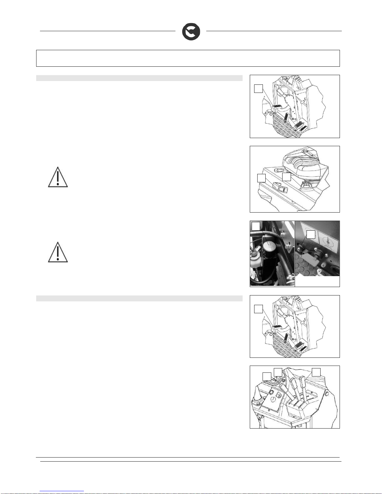
56
EXTRAORDINARY MAINTENANCE
59. MAINTENANCE OF THE HYDRAULIC FLUID
Proceed as follows in order to carry out maintenance of machine's hydraulic fluid:
1. Engage the parking brake, pressing the pedal (1)
2
. Check the main machine switch is in the “OFF-0” position. If this is not the case, turn the key by a
quarter rotation to the left.
3. Turn the cover rotation catch (2)
4
. Using the handle (3) rotate the rear cover as far as it will go
WARNING: Carry out this procedure only when the engine is off, with the engine at
ambient temperature, and with the machine parked on flat ground.
5. Unscrew the cap (4) of the oil tank
6. Put the fluid into the container, until it reaches the middle of the maximum filling bulb (5)
WARNING: Only use "ARNICA 46" oil that conforms to ISO-L-HV or DIN 51524 t.3
HVLP
WARNING: It is recommended that the above-mentioned operations be carried out
by personnel trained by the service centre.
60. REPLACING THE HYDRAULIC SYSTEM FILTER
Proceed as follows in order to carry out maintenance of the hydraulic system's filter :
1. Engage the parking brake, pressing the pedal (1)
2
. Check the main machine switch is in the “OFF-0” position. If this is not the case, turn the key by a
quarter rotation to the left.
3. Make sure that the central brush has been raised from the ground, if not use the lever (2)
4
. Make sure that the right side brush has been raised from the ground, if not use the lever (3)
5. Make sure that the left side brush (optional) has been raised from the ground, if not use the lever (4)
1
2
3
4 5
1
2
4 3

57
EXTRAORDINARY MAINTENANCE
6. Turn the cover rotation catch (5)
7. Using the handle (6) rotate the rear cover as far as it will go
WARNING: Carry out this procedure only when the engine is off, with the engine at
ambient temperature, and with the machine parked on flat ground.
7. Unscrew the cap (7) of the oil tank and cover the vent hole with insulating tape
8. Unscrew the cap (7) of the oil tank
WARNING: This operation must be carried out using gloves to protect against
contact with dangerous solutions.
8. Turn the knob (8) clockwise and open the left hatch
9. Place a collection tray under the filter of the hydraulic system (9)
10. Unscrew the hydraulic system filter (9)
11. Screw in the new hydraulic system filter (9)
12. Turn the knob (8) anticlockwise and close the left side hatch
9. Unscrew the cap (7) of the oil tank and remove the insulating tape on the vent hole
10. Screw in the cap (7) of the oil tank
WARNING: Dispose of the oil from the hydraulic system responsibly, comply with
current laws in your region for the disposal of used oil.
WARNING: It is recommended that the above-mentioned operations be carried out
by personnel trained by the service centre.
8
5
6
7
9

58
EXTRAORDINARY MAINTENANCE
61. REPLACING THE STARTER BATTERY (VERSIONS WITH COMBUSTION ENGINES)
Proceed as follows in order to carry out the replacement of the starter battery for machines with a
combustion engine:
1. Engage the parking brake, pressing the pedal (1)
2
. Check the main machine switch is in the “OFF-0” position. If this is not the case, turn the key by a
quarter rotation to the left.
3. Turn the cover rotation catch (2)
4
. Using the handle (3) rotate the rear cover as far as it will go
WARNING: Carry out this procedure only when the engine is off, with the engine at
ambient temperature, and with the machine parked on flat ground.
WARNING: It is recommended that the electrical connection operations be carried
out by personnel trained by the service centre.
5. With the proper equipment remove the cable of the negative "-" pole from the battery
6. With the proper equipment remove the cable of the positive "+" pole from the battery
WARNING: This operation must be carried out using gloves to protect against
contact with dangerous solutions.
7. With the proper equipment remove the locking blade (5), first unscrew the nut (4)
8. Remove the dead battery
9. Insert the new battery
WARNING: The new battery should meet the characteristics required by the technical
service centre, in order to ensure the sweeper works correctly.
10. With the proper equipment attach the cable of the positive "+" pole
11. With the proper equipment attach the cable of the negative "-" pole
WARNING: This operation must be carried out using gloves to protect against
contact with dangerous solutions.
WARNING: It is recommended that the above-mentioned operations be carried out
by personnel trained by the service centre.
1
2
3
5
4

59
EXTRAORDINARY MAINTENANCE
62. REPLACEMENT OF THE CENTRAL BRUSH'S REAR FLAP
If during working you notice that the machine leaves a trail of dust or dirt in its wake, this means that the
rear flap of the central brush needs replacing. Proceed as follows to replace it:
1. Engage the parking brake, pressing the pedal (1)
2. Check the main machine switch is in the “OFF-0” position. If this is not the case, turn the key by a
quarter rotation to the left.
3. Lower the central brush to the ground, using the lever (2)
4. Raise the right side brush from the ground, using the lever (3)
5. Raise the left side brush from the ground (if present as an optional), using the lever (4)
6. Turn the knob (5) anticlockwise and open the right hatch
7. Release the hinge (6) fixing the articulated arm (7) of the central brush
8. Remove the articulated arm (7) of the central brush from the arm (8) controlling the central brush
ATTENTION: This operation must be carried out using gloves to protect
against contact with dangerous substances.
9. Remove the articulated arm (7) of the central brush from the central brush (9)
10. Remove the central brush (9)
ATTENTION: This operation must be carried out using gloves to protect
against contact with dangerous substances.
1
2
4 3
5
6
7
8
9 7
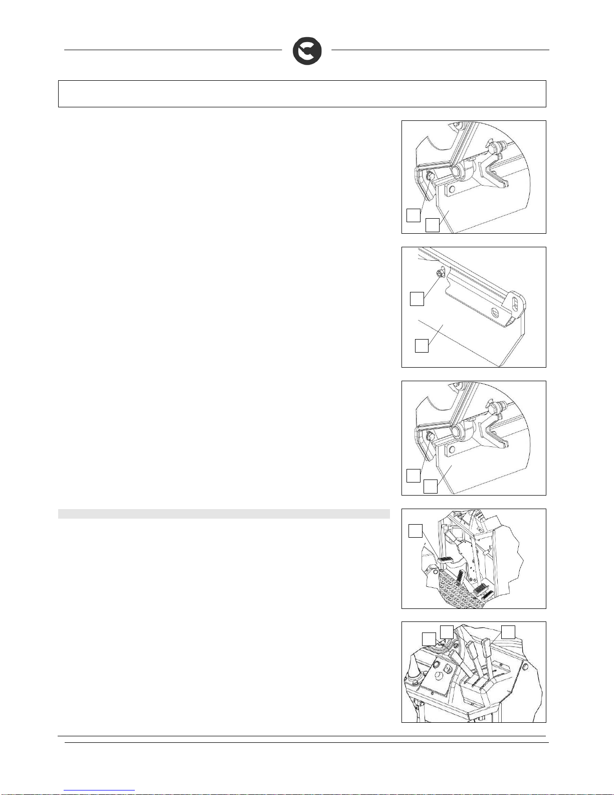
60
EXTRAORDINARY MAINTENANCE
11. Using the proper equipment remove the screws (10) that fix the rear flap support (11) to the frame of
the machine
12. Remove the rear flap support from the machine
13. Using the proper equipment, remove the nuts (12) that fix the rear flap (11) to the support
14. Remove the old rear flap (11) and put in the new one
15. Using the proper equipment, fix the nuts (12) that fix the rear flap (11) to the support, position the flap
in such a way that the fixing screws are about in the middle of the slits
16. Insert the rear flap support into the machine
17. Using the proper equipment insert the screws (10) that fix the rear flap support (11) to the frame of the
machine, do not fix then completely but leave them loose
18. Adjust the rear flap support (11) so that there are three millimetres between the work surface and the
rubber
19. Using the proper equipment tighten the screws (10) that fix the rear flap support (11) to the frame of
the machine
20. Reassemble all the elements
63. SIDE FLAP REPLACEMENT
If during working you notice that dust comes out from the side parts of the machine, this means that the
side flap of the central brush needs adjusting. Proceed as follows to replace it:
1. Engage the parking brake, pressing the pedal (1)
2
. Check the main machine switch is in the “OFF-0” position. If this is not the case, turn the key by a
quarter rotation to the left.
3. Lower the central brush to the ground, using the lever (2)
4
. Raise the right side brush from the ground, using the lever (3)
5. Raise the left side brush from the ground (if present as an optional), using the lever (4)
10
12
11
10
11
11
1
2
4 3
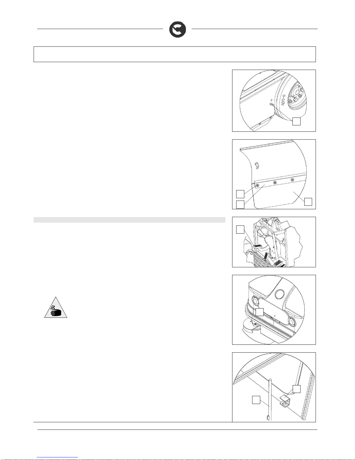
61
EXTRAORDINARY MAINTENANCE
6. Turn the knob (5) anticlockwise and open the right hatch
7. Using the proper equipment, remove the nuts (6) that fix the side rubber-pressing blade (7)
8. Remove the rubber-pressing blade (7)
9. Remove the more rigid worn side flap and insert the new one so that there are twenty millimetres
between the work surface and the rubber
10. Remove the worn side flap (8) and insert the new one so that there are three millimetres between the
work surface and the rubber
11. Insert the rubber-pressing blade (7)
12. Using the proper equipment, fix the nuts (6) that fix the side rubber-pressing blade (7)
64. REPLACEMENT OF HEADLIGHT BULB
To replace a headlight bulb,do as follows
1. Engage the parking brake, pressing the pedal (1)
2
. Check the main machine switch is in the “OFF-0” position. If this is not the case, turn the key by a
quarter rotation to the left.
3. Remove the rotation lock of the front cover
4
. Using the slot (2) turn the front cover as far as it will go
WARNING: This operation must be carried out using gloves to protect against
contact with dangerous solutions.
5. Block the rotation of the front cover, insert the pin (3) into the slot (4)
5
7
6
8
1
2
3
4

62
EXTRAORDINARY MAINTENANCE
6. Disconnect the headlight from the machine's electric system
7. Rotate the lamp socket (5) and unscrew it from the body of the headlight
8. Unscrew the burned out bulb and put in a new one
9. Reassemble all the elements
WARNING: All installation and maintenance operations must be carried out by
expert personnel, trained at the specialised assistance centre
WARNING: It is recommended that the above-mentioned operations be carried out
by personnel trained by the service centre.
5
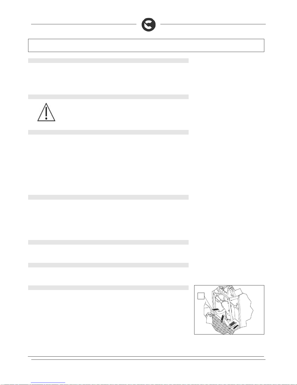
63
TROUBLESHOOTING
65. THE MACHINE DOES NOT START
1. Check the starter battery is connected to the machine system
2. Check the key switch is ON/I
3. Check the starter battery is charged
4. Check there is fuel in the motor tank
66. THE COMBUSTION ENGINE DOES NOT START
WARNING: If the combustion engine does not start, check the diagnostics in the
motor use and maintenance manual (the booklet supplied with the machine itself)
67. THE MACHINE DOES NOT CLEAN WELL
1. Check the state of wear and tear of the brushes and, if necessary, replace them. To replace them, see
“CENTRAL BRUSH REPLACEMENT”, or “SIDE BRUSH REPLACEMENT”. Working with over-worn
brushes may cause damage to the floor.
2. Use a different kind of brush to the one fitted as standard. For cleaning floors where the dirt is
particularly resistant, we recommend the use of special brushes supplied upon request and according
to needs (see “CHOOSING AND USING THE BRUSHES”).
3. The side brush is worn, to adjust it see “SIDE BRUSH ADJUSTMENT”.
4. The debris hopper is full, empty it completely.
68. THE MACHINE LIFTS DUST DURING OPERATION
1. The flaps that ensure efficient vacuum action are worn: replace them.
2. The front flap is broken and the machine projected heavy dirty bodies forward: replace them.
3. The filter is blocked: clean the filter thoroughly.
4. Check the central brush is correctly assembled
5. The debris hopper position is not correct
69. EXCESSIVE OR ALTERED NOISE OF THE CENTRAL BRUSH
1. Material wrapped around the brush: remove it.
70. EXCESSIVE OR ALTERED NOISE OF THE SIDE BRUSH
1. Material wrapped around the brush: remove it.
71. FUSES
The machine is equipped with the following electrical protection systems, power fuses housed in the
electrical box to protect against short-circuits. In the event of a fault, proceed as follows to check if a fuse
has tripped:
1. Engage the parking brake, pressing the pedal (1)
2
. Check the main machine switch is in the “OFF-0” position. If this is not the case, turn the key by a
quarter rotation to the left.
1
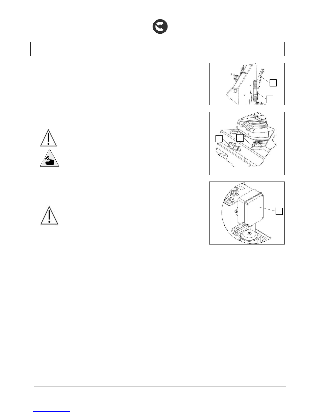
64
TROUBLESHOOTING
3. For battery versions, gripping the handle (2) disconnect the electrical system connector from the
battery connector (3)
4
. Turn the cover rotation catch (4)
5. Using the handle (5) rotate the rear cover as far as it will go
WARNING: Carry out this procedure only when the engine is off, with the engine at
ambient temperature, and with the machine parked on flat ground.
WARNING: This operation must be carried out using gloves to protect against
contact with dangerous solutions.
6. Using the proper equipment remove the cover (6) of the electrical box
7. Check the fuses one by one, replace the damaged one with one of the same resistance
8. Reassemble all the elements
WARNING: All installation and maintenance operations must be carried out by
expert personnel, trained at the specialised assistance centre
WARNING: It is recommended that the above-mentioned operations be carried out
by personnel trained by the service centre.
4
5
6 2 3

65
RECOMMENDED PERIODIC MAINTENANCE OPERATIONS
Version Procedure
Upon
delivery
Daily
mainte
nance
A
fter
the
first
50
hours
Every
50
hours
Every
150
hours
Every
300
hours
Every
500
hours
Every
1000
hours
Every
2000
hours
Every
3000
hours
B - D Hydraulic oil level
check
C C
B - D Parking brake check C
B - D Brush cleaning C
B - D Replacement of central
brush
S (2) S (2) S (2)
B - D Side brush
replacement
S (3) S (3) S (3) S (3)
B - D External cleaning of
hydraulic oil radiator
C
B - D Brush adjustment
check
S S S S
B - D Filter shaker
functioning check
C C
B - D Flap condition check
C
B - D Flap replacement
S (4) S (4)
B - D Seal condition check
(oil leaks)
S S S S
B - D Bearing greasing
S S S
S
B - D Hydraulic oil
replacement
S (1) S (1)
B - D Hydraulic oil filter
replacement
S S S
D Check for leaks in
cooling circuit
C C
D Engine coolant check C C
D Engine oil replacement S
S
S
D Engine oil replacement S
S
S
D Engine air filter
cleaning
C
D Engine air filter
cleaning
S
D
A
lternator belt check C C
D Battery liquid level
check
C C C C C
D External cleaning of
motor radiator
C
D Fuel filter replacement
S
S
D Motor alternator belt
replacement
S
D Tightening of screws
and fuel fittings
S S S
D Motor valve play check
S
D Motor vent
replacement
S
D Injector yield check
S
KEY:
B= battery - D= diesel
(1) =The first time after 500 hours, then every 1000 hours
(2) =Every 250 hours if the ground is smooth; every 150 hours if it is rough
(3) =Every 175 hours if the ground is smooth; every 100 hours if it is rough
(4) =Every 500 hours if the ground is smooth; every 300 hours if it is rough
B versions: for battery maintenance, respect the manufacturer's indications
Operations to be carried out by the user (C) or the Technical Assistance Service (S)

66
DISPOSAL
To dispose of the machine, take it to a demolition centre or an authorised collection centre.
Before scrapping the machine it is necessary to remove and separate the following materials and send
them to the appropriate collection centres in accordance with the environmental hygiene regulations
currently in force:
brushes
felt
electric and electronic parts*
batteries
plastic parts (tanks and handlebars)
metal parts (levers and frame)
(*) In particular, to scrap the electric and electronic parts, contact your area distributor.

67
CHOOSING AND USING THE BRUSHES
POLYPROPYLENE BRUSH (PPL)
It is used on every type of floors and has good resistance to wear. The Polypropylene brush is non-hygroscopic and therefore retains its characteristics even
when working in wet conditions.
TABLE FOR CHOOSING THE BRUSHES
Machine No. of brushes. Code Type of bristles
Bristles
Brushes
Length. Notes
CS90
1
430414
431385
431386
437251
PPL
PPL
PPL
PPL + ACC
1.1 + 0.7
1.4
0.7
1.4 + 0.35
320 895 CENTRAL BRUSH
1-2
429205
429206
PPL + ACC
PPL
1.1 + 0.7
1
450 SIDE BRUSH
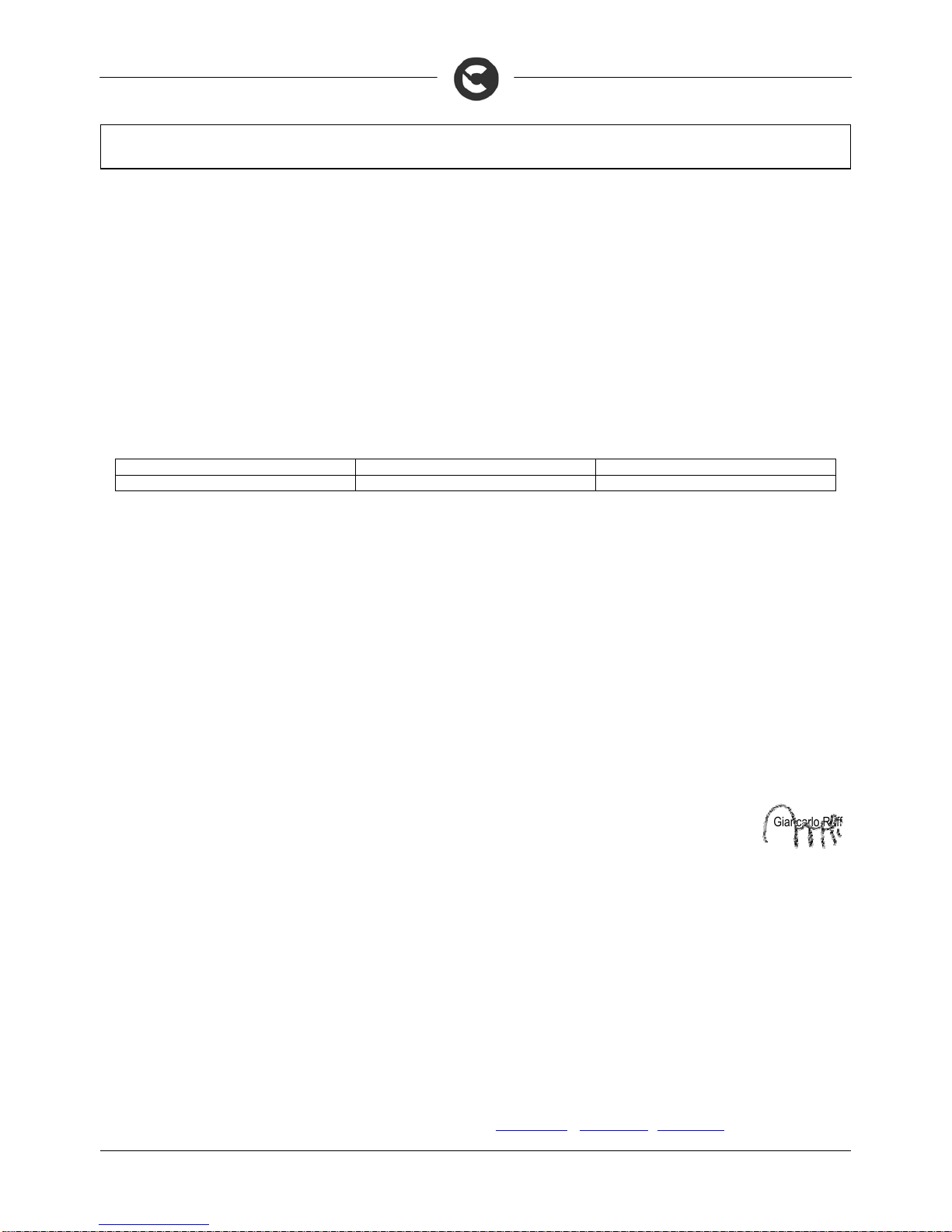
68
EC DECLARATION OF CONFORMITY
The undersigned manufacturer:
COMAC S.p.A.
Via Maestri del Lavoro, 13
37059 Santa Maria di Zevio (VR)
declares under its sole responsibility that the product
SWEEPING MACHINES: CS90 B
complies with the requirements of the following Directives:
2006/42/EC: Machinery Directive.
2004/108/EC: Electromagnetic Compatibility Directive.
2000/14/EC: Directive by the European Parliament and Council date 8th May, 2000. Noise emission by machines and equipment for outdoor use.
Falling into the category of road sweeper as defined in Annex 46 of Directive 2000/14/EC of the European Parliament and the Council, is subject to noise
marking only.
The conformity evaluation was carried out in accordance with enclosure III.B.46 of the said directive.
MODEL LwA [dB(A)]
LwA, guaranteed [dB(A)]
CS90 B 71
93
They also comply with the following standards:
EN 60335-1: Household and similar electrical appliances - Safety. Part 1: Generic standards.
EN 60335-2-72: Household and similar electrical appliances. Part 2: Generic standards for automatic machines for floor treatment for commercial and
industrial use.
EN 12100-1: Machine safety - Fundamental concepts, fundamental principles of design - Part 1: Basic terminology and methodology.
EN 12100-2: Machine safety - Fundamental concepts, fundamental principles of design - Part 2: Technical principles.
EN 61000-6-2: Electromagnetic compatibility (EMC) - Part 6-2: Generic standards – Immunity for industrial environments.
EN 61000-6-3: Electromagnetic compatibility (EMC) - Part 6-3: Generic standards — Standard emission for residential, commercial and light-industrial
environments.
EN 62233: Household and similar electrical appliances - Electromagnetic fields Methods for evaluation and measurement.
The person authorised to compile the technical file:
Sig. Giancarlo Ruffo
Via Maestri del Lavoro, 13
37059 Santa Maria di Zevio (VR) - ITALY
Santa Maria di Zevio (VR), 01/09/2010
COMAC S.p.A.
Legal representative
Giancarlo Ruffo
COMAC spa
Via Maestri del Lavoro, 13 – 37059 Santa Maria di Zevio – Verona – ITALY
Tel. +39 045 8774222 – Fax +39 045 8750303 - E-mail: com@comac.it
o info@comac.it - www.comac.it

69
EC DECLARATION OF CONFORMITY
The undersigned manufacturer:
COMAC S.p.A.
Via Maestri del Lavoro, 13
37059 Santa Maria di Zevio (VR)
declares under its sole responsibility that the product
SWEEPING MACHINES: CS90 D
complies with the requirements of the following Directives:
2006/42/EC: Machinery Directive.
2004/108/EC: Electromagnetic Compatibility Directive.
2000/14/EC: Directive by the European Parliament and Council date 8th May, 2000. Noise emission by machines and equipment for outdoor use.
Falling into the category of road sweeper as defined in Annex 46 of Directive 2000/14/EC of the European Parliament and the Council, is subject to noise
marking only.
The conformity evaluation was carried out in accordance with enclosure III.B.46 of the said directive.
MODEL LwA [dB(A)]
LwA, guaranteed [dB(A)]
CS90 D 84
102
They also comply with the following standards:
EN 60335-1: Household and similar electrical appliances - Safety. Part 1: Generic standards.
EN 60335-2-72: Household and similar electrical appliances. Part 2: Generic standards for automatic machines for floor treatment for commercial and
industrial use.
EN 12100-1: Machine safety - Fundamental concepts, fundamental principles of design - Part 1: Basic terminology and methodology.
EN 12100-2: Machine safety - Fundamental concepts, fundamental principles of design - Part 2: Technical principles.
EN 61000-6-2: Electromagnetic compatibility (EMC) - Part 6-2: Generic standards – Immunity for industrial environments.
EN 61000-6-3: Electromagnetic compatibility (EMC) - Part 6-3: Generic standards — Standard emission for residential, commercial and light-industrial
environments.
EN 62233: Household and similar electrical appliances - Electromagnetic fields Methods for evaluation and measurement.
The person authorised to compile the technical file:
Sig. Giancarlo Ruffo
Via Maestri del Lavoro, 13
37059 Santa Maria di Zevio (VR) - ITALY
Santa Maria di Zevio (VR), 01/09/2010
COMAC S.p.A.
Legal representative
Giancarlo Ruffo
COMAC spa
Via Maestri del Lavoro, 13 – 37059 Santa Maria di Zevio – Verona – ITALY
Tel. +39 045 8774222 – Fax +39 045 8750303 - E-mail: com@comac.it
o info@comac.it - www.comac.it
 Loading...