

Page 1

SUMMARY
SUMMARY
SUMMARYSUMMARY
ON CONSIGNMENT OF THE MACHINE
ON CONSIGNMENT OF THE MACHINE .............................................................................................................. 24
ON CONSIGNMENT OF THE MACHINEON CONSIGNMENT OF THE MACHINE
INTRODUCTORY COMMENT
INTRODUCTORY COMMENT .......................................................................................................................... 24
INTRODUCTORY COMMENTINTRODUCTORY COMMENT
TECHNICAL DESRIPTION
TECHNICAL DESRIPTION.............................................................................................................................. 24
TECHNICAL DESRIPTIONTECHNICAL DESRIPTION
SYMBOLOGY USED ON THE MACHINE
SYMBOLOGY USED ON THE MACHINE ............................................................................................................. 25
SYMBOLOGY USED ON THE MACHINESYMBOLOGY USED ON THE MACHINE
SYMBOLOGY USED IN THE MANUAL
SYMBOLOGY USED IN THE MANUAL ............................................................................................................... 26
SYMBOLOGY USED IN THE MANUALSYMBOLOGY USED IN THE MANUAL
MACHINE PREPARATION
MACHINE PREPARATION.............................................................................................................................. 27
MACHINE PREPARATIONMACHINE PREPARATION
HANDLING OF THE PACKED MACHINE .......................................................................................................................................... 27
HOW TO UNPACK THE MACHINE.................................................................................................................................................. 27
BATTERY TYPE ........................................................................................................................................................................... 28
INSTALLING THE BATTERIES ....................................................................................................................................................... 28
CONNECTING THE BATTERY CHARGER ......................................................................................................................................... 28
BATTERY CHARGER .................................................................................................................................................................... 29
BATTERY CHARGE LEVEL GAUGE ................................................................................................................................................ 29
INSTALLING THE SQUEEGEE ........................................................................................................................................................ 29
SQUEEGEE HEIGHT ADJUSTING ................................................................................................................................................... 30
SQUEEGEE INCLINATION ADJUSTING ........................................................................................................................................... 30
RECOVERY TANK ........................................................................................................................................................................ 30
SOLUTION WATER ...................................................................................................................................................................... 30
INSTALLING THE SPLASH-GUARD................................................................................................................................................ 31
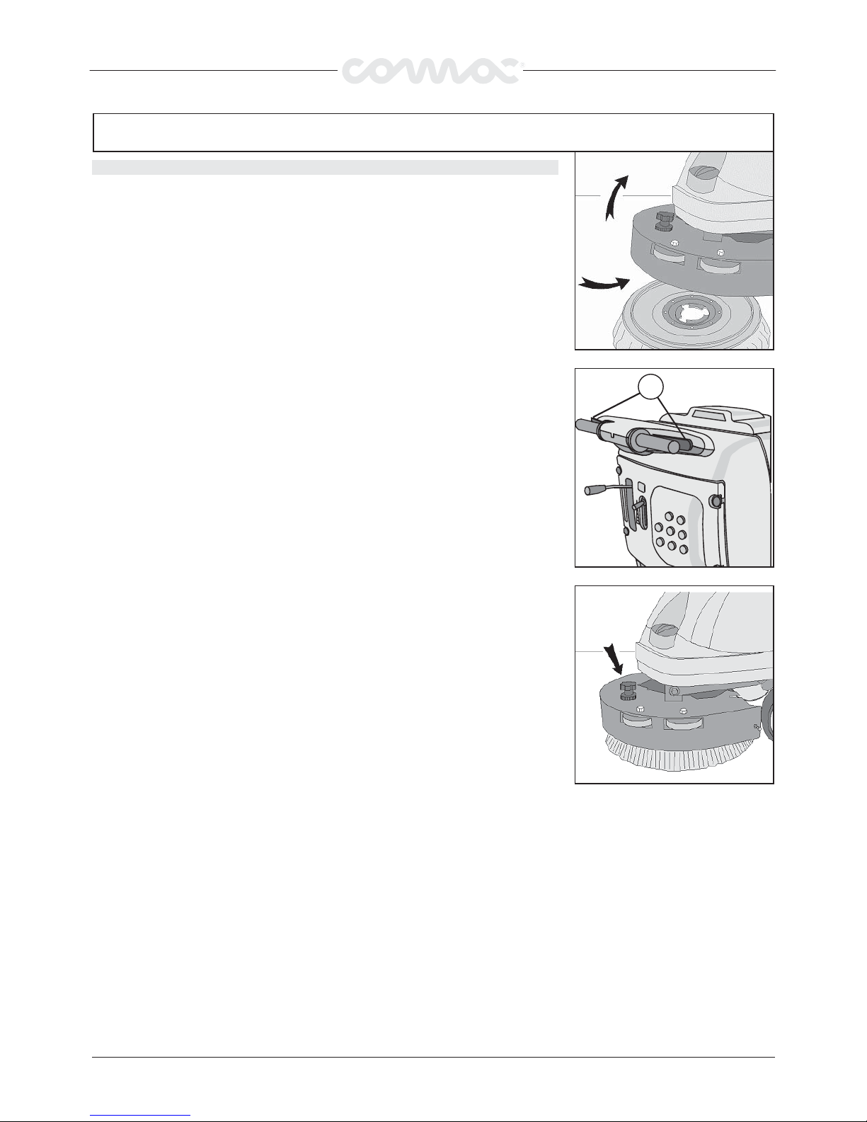
INSTALLING THE BRUSH 42-52 ................................................................................................................................................... 31
BRUSH ASSEMBLY ABILA 17 ...................................................................................................................................................... 32
GENERAL SECURITY RULES
GENERAL SECURITY RULES.......................................................................................................................... 33
GENERAL SECURITY RULESGENERAL SECURITY RULES
WORK
WORK...................................................................................................................................................... 34
WORKWORK
WORK PREPARATION.................................................................................................................................................................. 34
OVERFLOW DEVICE.................................................................................................................................................................... 35
TRACTION ................................................................................................................................................................................. 35
UPON COMPLETION OF WORK
UPON COMPLETION OF WORK....................................................................................................................... 36
UPON COMPLETION OF WORKUPON COMPLETION OF WORK
DAILY MAINTENANCE
DAILY MAINTENANCE .................................................................................................................................. 37
DAILY MAINTENANCEDAILY MAINTENANCE
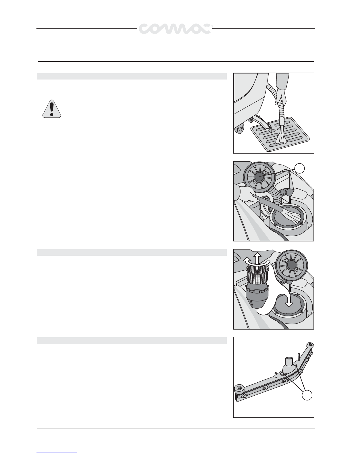
RECOVERY TANK CLEANING........................................................................................................................................................ 37
SUCTION FILTER CLEANING......................................................................................................................................................... 37
SQUEEGEE CLEANING ................................................................................................................................................................. 37
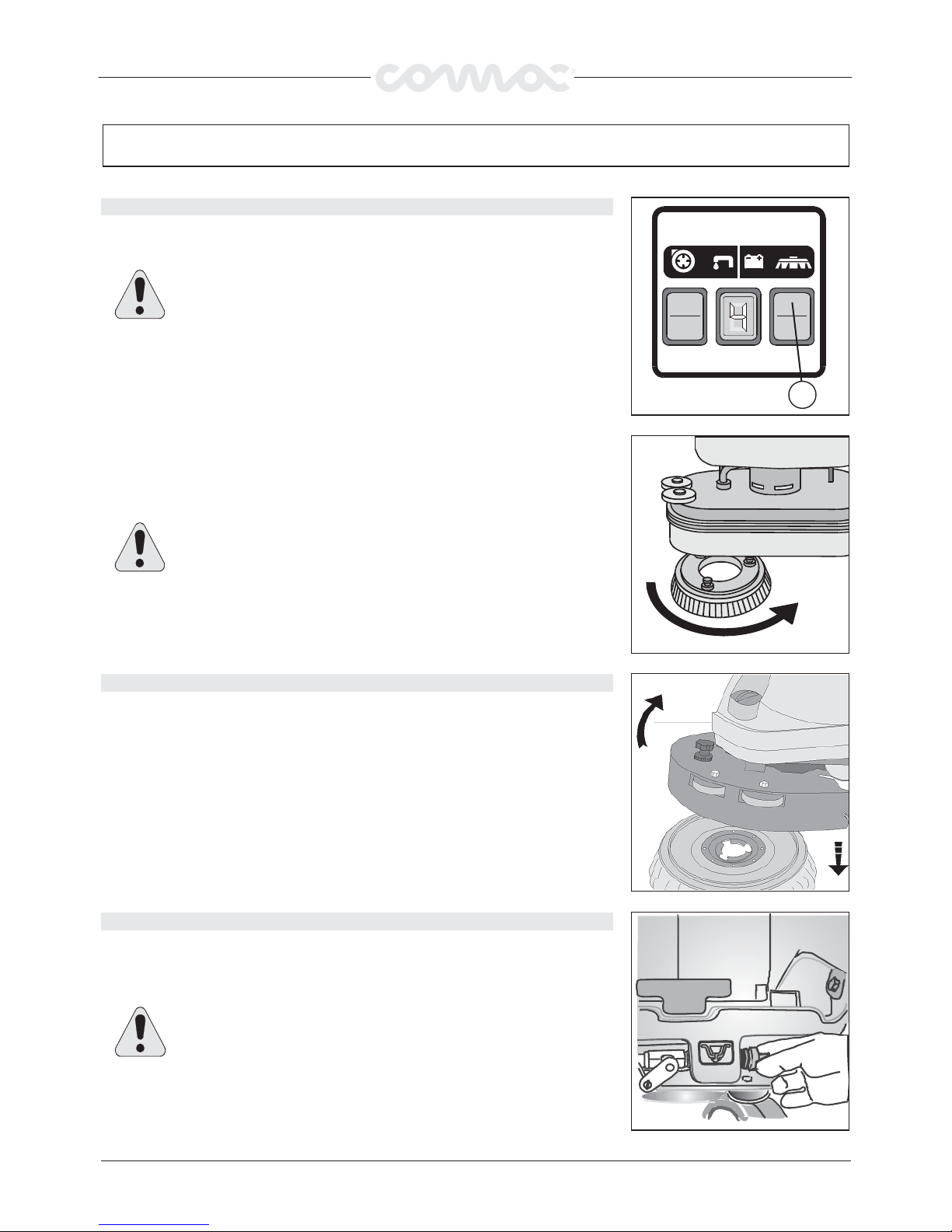
BRUSHES DISASSEMBLY ABILA 42 52......................................................................................................................................... 38
BRUSHES DISASSEMBLY ABILA 17 ............................................................................................................................................. 38
CLEANING SOLUTION FILTER....................................................................................................................................................... 38
WEEKLY MAINTENANCE
WEEKLY MAINTENANCE............................................................................................................................... 39
WEEKLY MAINTENANCEWEEKLY MAINTENANCE
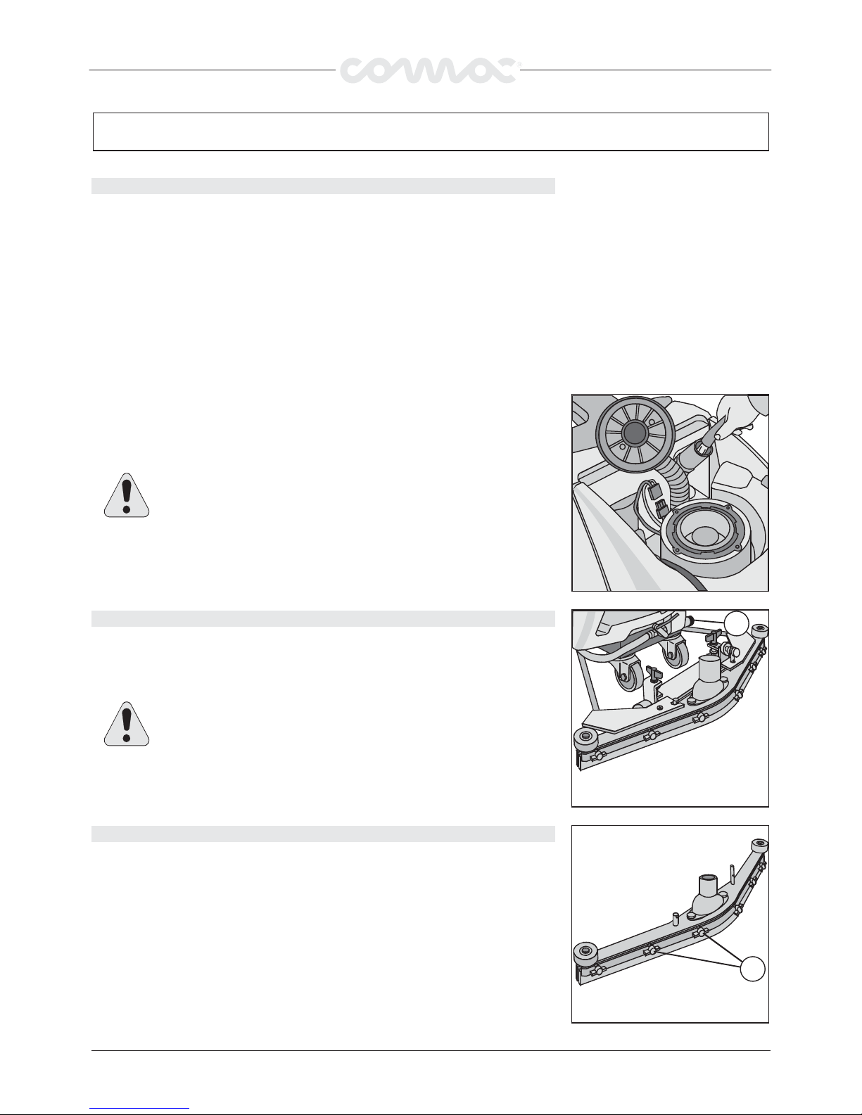
CLEANING SQUEEGEE HOSE ........................................................................................................................................................ 39
CLEANING SOLUTION TANK......................................................................................................................................................... 39
REAR SQUEEGEE RUBBERS REPLACEMENT .................................................................................................................................. 39
WORKING CONTROL
WORKING CONTROL ................................................................................................................................... 40
WORKING CONTROLWORKING CONTROL
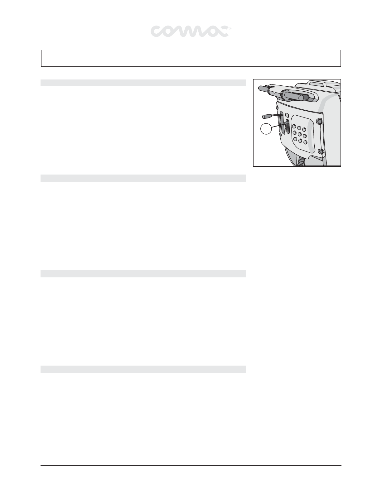
INSUFFICIENT WATER TO THE BRUSHES....................................................................................................................................... 40
THE MACHINE DOES NOT CLEAN PROPERLY................................................................................................................................. 40
THE SQUEEGEE DOES NOT DRY PERFECTLY.................................................................................................................................. 40
FOAM OVER-FORMATION ............................................................................................................................................................ 40
CHOICE AND USE OF BRUSHES
CHOICE AND USE OF BRUSHES...................................................................................................................... 41
CHOICE AND USE OF BRUSHESCHOICE AND USE OF BRUSHES
23
Page 2
On consignment of the machine
On consignment of the machine
On consignment of the machineOn consignment of the machine
When the machine is consigned to the customer, an immediate check
must be performed to ensure all the material mentioned in the
shipping documents have been received and moreover to find out that
the machine has not suffered damage during transportation. If damage
has occurred, get the shipping agent to verify immediately the amount
and nature of the damage suffered and at the same time inform our
claim department. It is only by prompt action of this type that
compensation for damage may be successfully claimed.
Introductory comment
Introductory comment
Introductory commentIntroductory comment
This is a sweep-scrubbing machine which, using the mechanic
abrasive action of two rotary brushes and the chemical action of a
solution water-detergent, is able to clean any type of floor, picking up
during its advance movement, the removed dirt and the detergent
solution which has not been absorbed from the floor.
The machine must be used only for such purpose
The machine must be used only for such purpose. We would impress
The machine must be used only for such purposeThe machine must be used only for such purpose
upon you that any machine will function efficiently and operate
successfully, only if used correctly and maintained in fully efficient
working order. We therefore suggest you to read this instruction
booklet carefully and re-read it whenever difficulties arise in the course
of machine use. Our Service Department is at your disposal for all
such advice and servicing as may prove necessary.
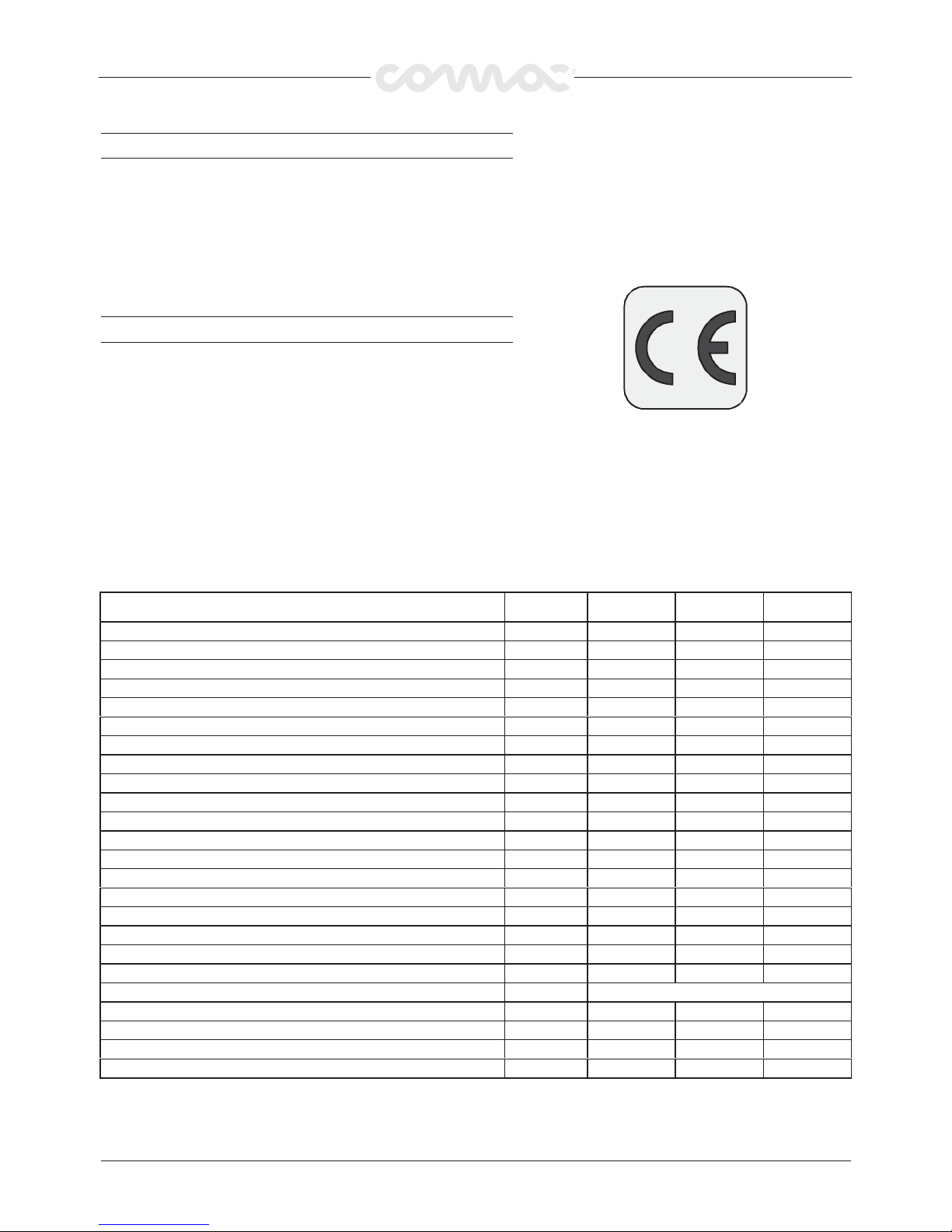
ABILA 42
ABILA 42 ABILA 52
U/M
U/M ABILA 17
TECHNICAL DESRIPTION
TECHNICAL DESRIPTION
TECHNICAL DESRIPTIONTECHNICAL DESRIPTION
Cleaning width Mm 420 400 500
Squeegee width Mm 660 660 660
Working capacity, up to Sqm/h 1470 1400 1750
Brushes diameter Mm 1x420 2x210 2x255
Brushes speed Rpm 140 340 275
Brushes pressure Kg 20 max 20 max 22 max
Brush motor, nominal power W 400 400 400
Drive type semi-aut. semi-aut. semi-aut.
Max. movement speed km/h 3,5 3,5 3,5
Max. gradient 2% 2% 2%
Suction motor, nominal power W 370 370 370
Suction vacuum Mbar 100 100 100
Solution tank L 33 33 33
Recovery tank L 40 40 40
Machine length Mm 1060 1060 1100
Machine height Mm 960 960 960
Machine width (without squeegee) Mm 455 455 565
Batteries (voltage) V 24 24 24
Batteries (max. capacity) Ah 70 70 70
Batteries (compartment) Mm 360x330x250
Batteries weight Kg 40 40 40
Machine weight (empty and without batteries) Kg 70 70 72
Acoustic radiation pressure level (EN 60704-1) db (A) <65 <65 <65
Vibration level m/sqs 1.00 1.00 1.00
U/MU/M
ABILA 17
ABILA 17ABILA 17
ABILA 42ABILA 42
ABILA 52
ABILA 52ABILA 52
24
Page 3
SYMBOLOGY USED ON THE MACHINE
SYMBOLOGY USED ON THE MACHINE
SYMBOLOGY USED ON THE MACHINESYMBOLOGY USED ON THE MACHINE
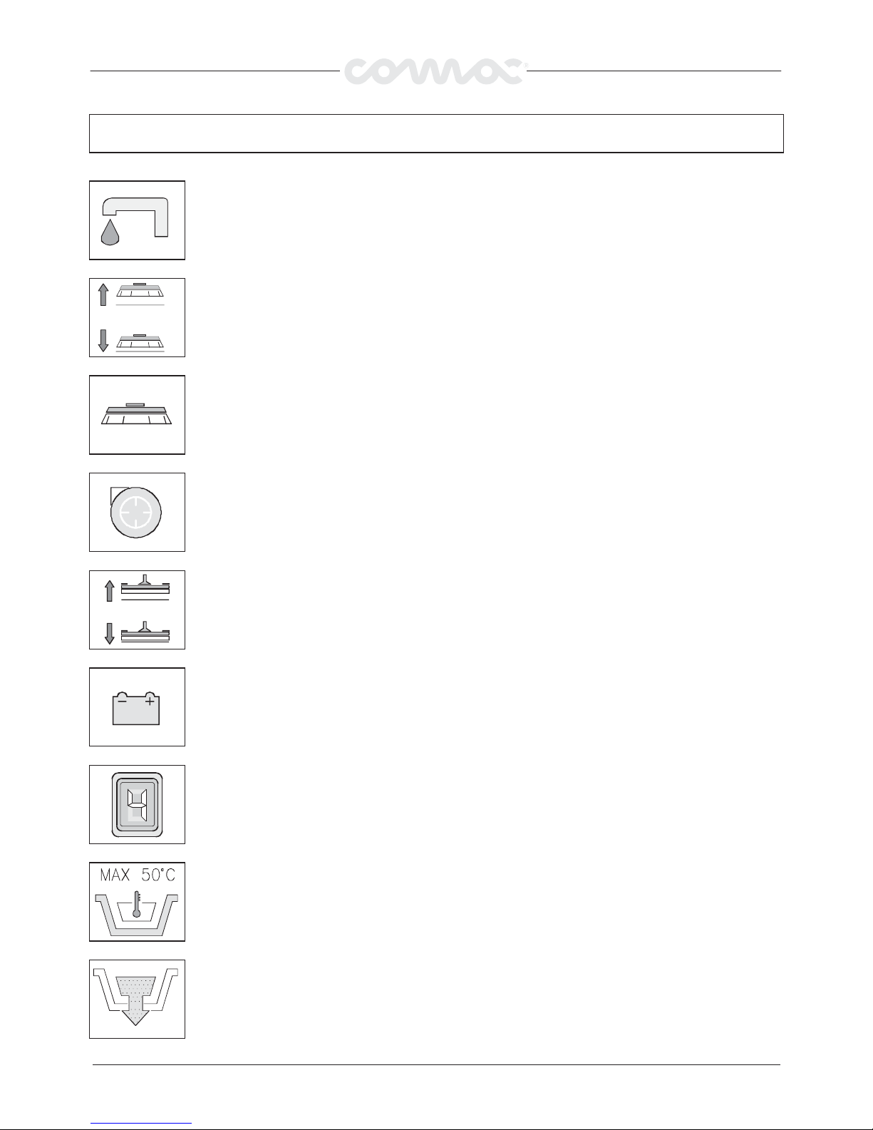
Cock symbol
Indicates the cock lever
Indicates the cock open signal lamp
Squeegee base lift/lower symbol
Indicates the base lift lever
Brush symbol
Indicates the brush motor switch
Suction motor symbol
Indicates the suction motor switch
Squeegee lift/lower symbol
Indicates the squeegee lift lever
Battery symbol
Indicator of the battery charge level
Indicates also the position of the cock level (switched off = cock closed, switched on = opened cock)
Indicates the detergent solution maximum temperature
It is placed closed to the solution tank inlet opening.
Indicated the recovery tank outlet pipe
25
Page 4
SYMBOLOGY USED ON THE MACHINE
SYMBOLOGY USED ON THE MACHINE
SYMBOLOGY USED ON THE MACHINESYMBOLOGY USED ON THE MACHINE
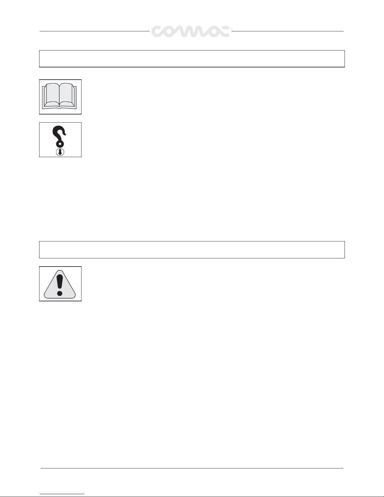
Open book symbol
Indicates to the operator to read the manual before using the machine.
Hooking symbol
Indicates anchoring points and loading direction.
SYMBOLOGY USED IN THE MANUAL
SYMBOLOGY USED IN THE MANUAL
SYMBOLOGY USED IN THE MANUALSYMBOLOGY USED IN THE MANUAL
Warning symbol
Carefully read the sections marked with this symbol, for the security of both the operator and the
machine.
26
Page 5
MACHINE PREPARATION
MACHINE PREPARATION
MACHINE PREPARATIONMACHINE PREPARATION
HANDLING OF THE PACKED MACHINE
HANDLING OF THE PACKED MACHINE
HANDLING OF THE PACKED MACHINEHANDLING OF THE PACKED MACHINE
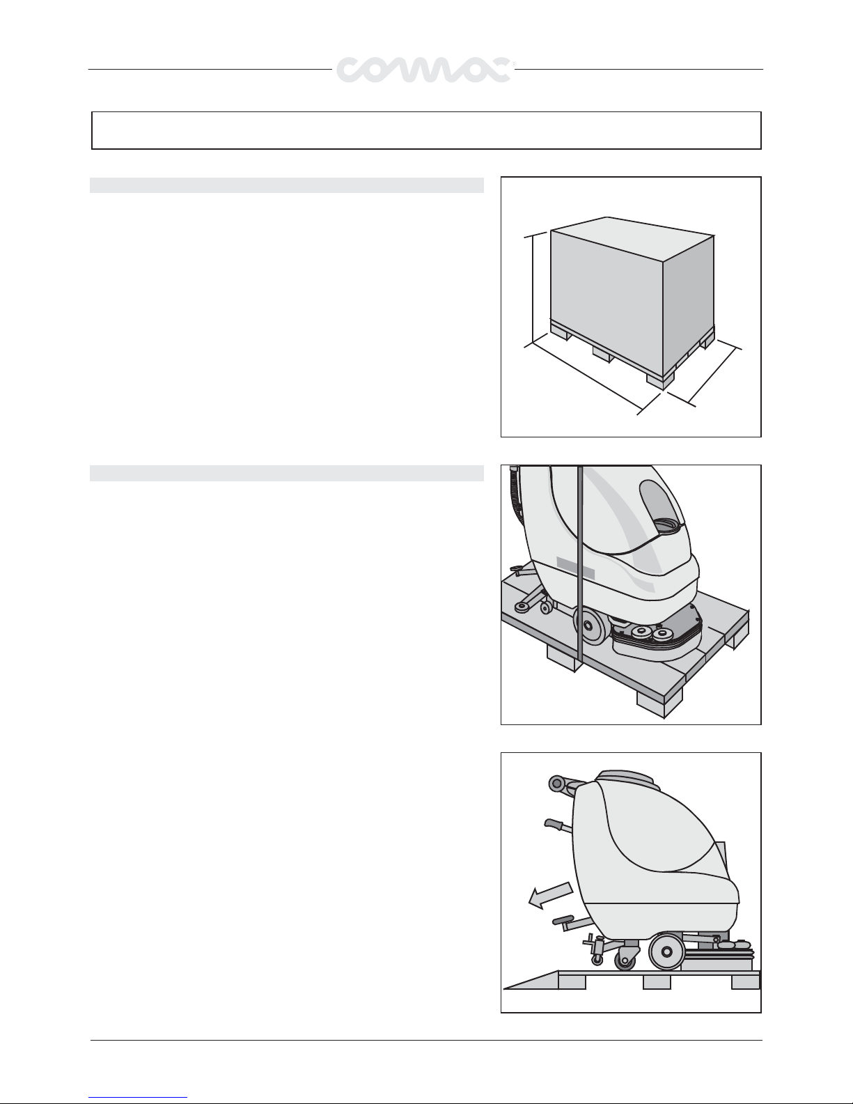
The machine is contained in specific packing with a platform so that a
forklift can move it. No more than two packages can be stacked on each
other.
The total weight is: -Abila 42: 136 kg
-Abila 52: 138 kg
-Abila 17: 136 kg
Packing dimensions are the following:
AAAA : 1260 mm
BBBB : 660 mm
CCCC : 1230 mm
HOW TO UNPACK THE MACHINE
HOW TO UNPACK THE MACHINE
HOW TO UNPACK THE MACHINEHOW TO UNPACK THE MACHINE
1. Remove outer packing.
2. The machine is strapped to its platform.
3. Remove the strap.
A
C
B
4. Use a ramp to lower the machine from the platform, pushing it
backward in reverse. Avoid violent blows against the base.
5. Keep the packing platform for future transport necessities.
27
Page 6
MACHINE PREPARATION
MACHINE PREPARATION
MACHINE PREPARATIONMACHINE PREPARATION
BATTERY TYPE
BATTERY TYPE
BATTERY TYPEBATTERY TYPE
For the energy supply of the machine use two:
• lead batteries for traction use and tubular plates and electrolyte free;
• or battery hermetically sealed for traction recombination of gas with gel technology.
Every battery is compound of elements that are connected in order to get a voltage of 12
V at the holdfasts.
The max. dimensions of every battery should be: width 195 mm, length 360 mm, height
250 mm.
The max. weight of every of the two batteries should be 20kg.
In order to achieve a tension of 24V the batteries must be connected with a serial
connection between them and the connection process has to be carried out by
specialised persons, which are trained by a Comac service centre.
INSTALLING THE BATTERIES
INSTALLING THE BATTERIES
INSTALLING THE BATTERIESINSTALLING THE BATTERIES
Battery must be housed in the battery compartment below the recovery tank, and must
be handled using special hoisting equipment with suitable grasping systems and
designed to support the battery weight.
The battery must also conform to the requirements given in CEI 21-5 standards.
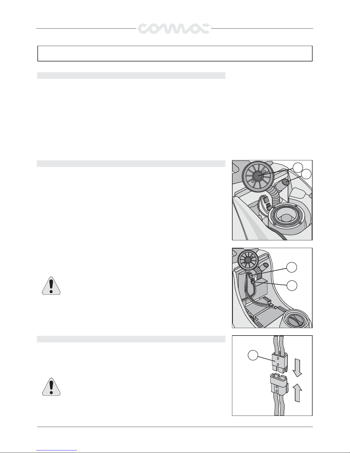
Battery installation procedure:
1. Open the recovery tank lid forward.
2. Disconnect the squeegee cable (1) from the recovery tank.
3. Remove the suction cap (2) by turning it in anticlockwise sense.
4. Disconnect the “recovery tank “ outlet pipe from the proper hook.
5. Remove the recovery tank.
2
1
6. Place the battery.
7. Connect the battery connector (2) to the machine connector (1).
8. Reassemble everything.
ATTENTION!
ATTENTION! The installation process has to be carried out by specialised
ATTENTION!ATTENTION!
persons.
CONNECTING THE BATTERY CHARGER
CONNECTING THE BATTERY CHARGER
CONNECTING THE BATTERY CHARGERCONNECTING THE BATTERY CHARGER
The battery connector (2), in which the battery charger connector is to be inserted, is
placed under the recovery tank cap. The battery charger connector is delivered inside
the bag containing this instruction booklet, and must be fitted to the battery charger
cables according to instructions.
ATTENTION!
ATTENTION! This procedure is to be carried out by specialists. A wrong
ATTENTION!ATTENTION!
or defective connection of the cables to the connectors can cause serious
damages persons and things.
2
1
2
28
Page 7
MACHINE PREPARATION
MACHINE PREPARATION
MACHINE PREPARATIONMACHINE PREPARATION
BATTERY CHARGER
BATTERY CHARGER
BATTERY CHARGERBATTERY CHARGER
Make sure that the battery charger is suitable to the installed battery, both in capacity
and in type (lead/acid or GEL and equivalent).
WARNING! Never charge a GEL battery with an unsuitable battery
WARNING! Never charge a GEL battery with an unsuitable battery
WARNING! Never charge a GEL battery with an unsuitable batteryWARNING! Never charge a GEL battery with an unsuitable battery
charger. Strictly follow the instructions provided by the battery and
charger. Strictly follow the instructions provided by the battery and
charger. Strictly follow the instructions provided by the battery andcharger. Strictly follow the instructions provided by the battery and
battery charger manufacturer.
battery charger manufacturer.
battery charger manufacturer.battery charger manufacturer.
In order to avoid permanent damages to the battery, they should never be
totally discharged. To do this, they should be recharged within a few
minutes after the battery discharge signal starts to flash.
NOTE
NOTE: Never left the battery completely discharged, not even if the
NOTENOTE
machine is not being used.
ATTENTION!
ATTENTION! For the daily recharging of the battery it is necessary to
ATTENTION!ATTENTION!
strictly follow the instructions provided by the manufacturer or dealer.
Specialists must carry out all installing and maintenance procedures.
Danger of exhalation of gas and emission of corroding substances.
Danger of fire: keep away from flames.
BATTERY CHARGE LEVEL GAUGE
BATTERY CHARGE LEVEL GAUGE
BATTERY CHARGE LEVEL GAUGE BATTERY CHARGE LEVEL GAUGE
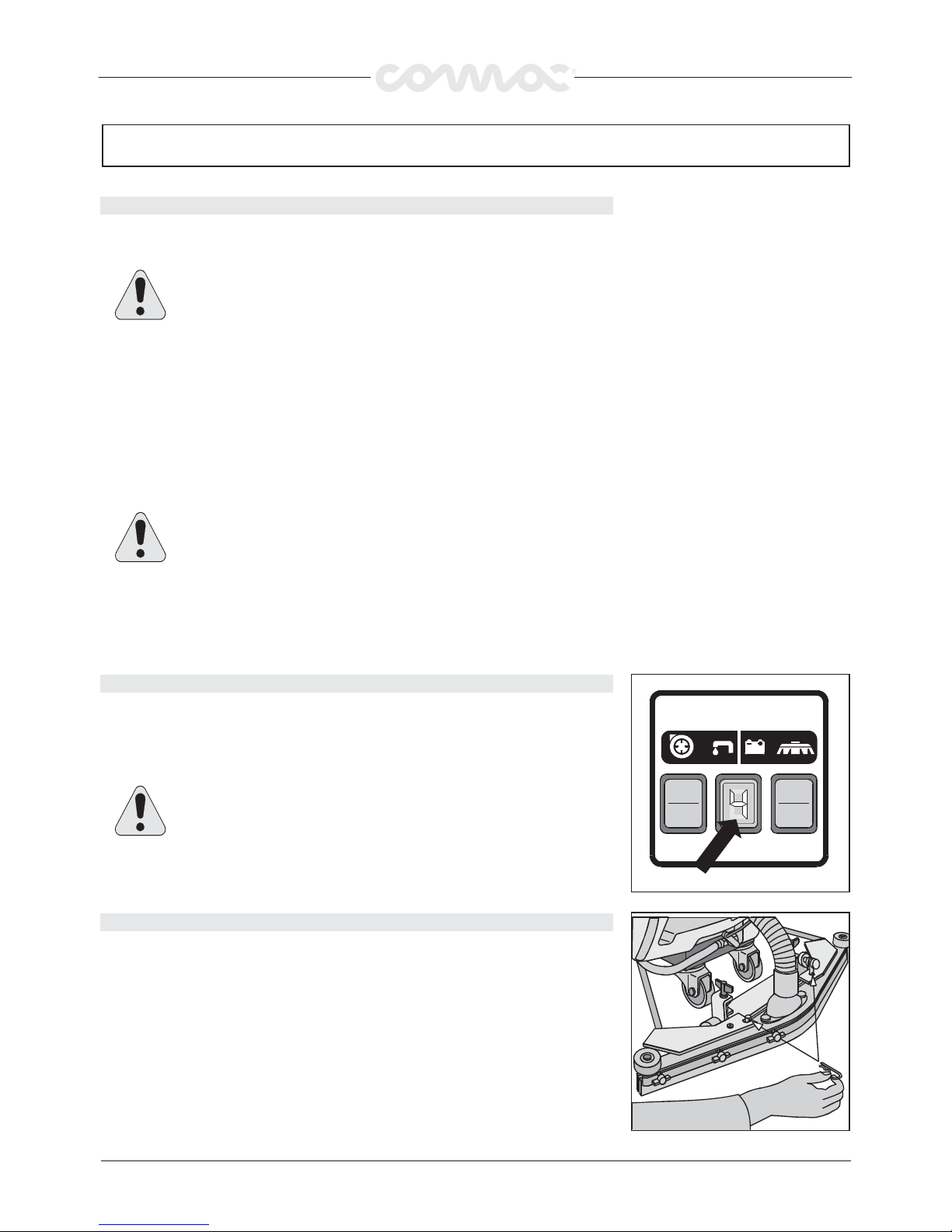
The batteries’ indicator is digital with 4 fixed positions and a blinking one. The numbers,
which appear on the display, show the approximate charge level.
4444 = maximum charge, 3333 = charge 3/4, 2222 = charge 2/4, 1111 = charge 1/4,
0000 = (blinking) discharged batteries)
WARNING!
WARNING!
WARNING!WARNING!
automatically switches off. Anyway, the machine can finish to dry before
recharging the batteries.
INSTALLING THE SQUEEGEE
INSTALLING THE SQUEEGEE
INSTALLING THE SQUEEGEEINSTALLING THE SQUEEGEE
The squeegee is supplied separately from the machine, due to packing reasons. It must
be installed as shown in the picture, threading the retaining pin into the squeegee
column. Put the squeegee suction tube into its sleeve.
Some seconds after that “0” blinks, the brush motor
29
Page 8
MACHINE PREPARATION
MACHINE PREPARATION
MACHINE PREPARATIONMACHINE PREPARATION
SQUEEGEE HEIGHT ADJUSTING
SQUEEGEE HEIGHT ADJUSTING
SQUEEGEE HEIGHT ADJUSTINGSQUEEGEE HEIGHT ADJUSTING
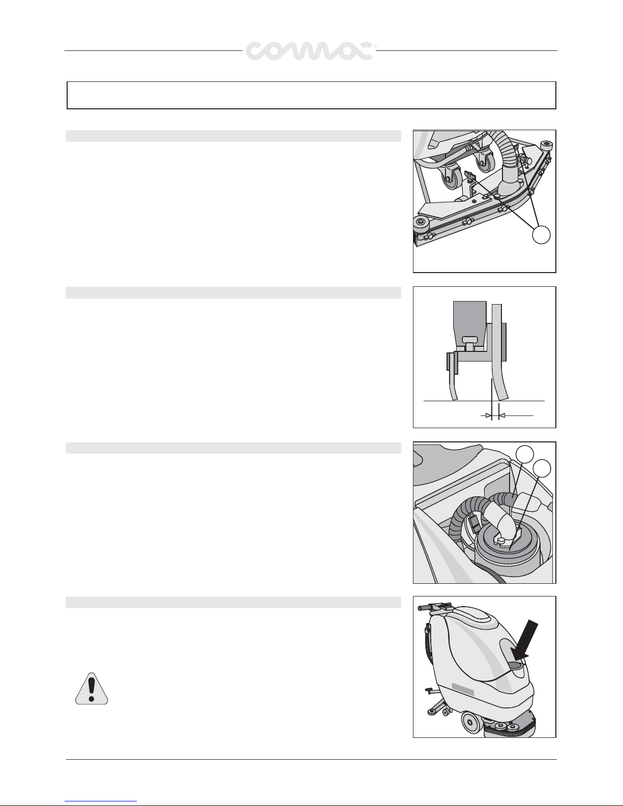
The squeegee height is to be regulated according to rubbers wearing. To adjust this:
rotate the wing nuts (1) anticlockwise to lift the squeegee and clockwise to lower it.
Note: The right and left wheels must undergo the same regulation, to allow the
squeegee to work parallel to the ground.
SQUEEGEE INCLINATION ADJUSTING
SQUEEGEE INCLINATION ADJUSTING
SQUEEGEE INCLINATION ADJUSTINGSQUEEGEE INCLINATION ADJUSTING
During the running, the back rubber is to be lightly inclined backwards (about 5 mm, on
its whole length). Should it be necessary, you can increase the rubber central inclination
by inclining backwards the squeegee body, turning the regulator anticlockwise (1). To
increase the bending of the rubber on the squeegee sides, turn the register clockwise.
Once the regulation is finished, lock the block nut.
1
RECOVERY TANK
RECOVERY TANK
RECOVERY TANKRECOVERY TANK
Open the cover and check if the suction plug (2) is insert correctly and its notches are
blocked turning the plug clockwise and is well connected with the hose which leads to
the suction motor.
Furthermore check, that the squeegee hose (1) is well connected and that the exhaust
plug at the back of the machine is closed.
SOLUTION WATER
SOLUTION WATER
SOLUTION WATERSOLUTION WATER
Fill the solution tank with clean water at a temperature not in excess of 50
detergent in the amounts and using the procedures recommended by the detergent
manufacturer. Use only a minimal percentage of detergent to prevent formation of an
excessive quantity of foam, as this could damage the suction motor. Close the cap.
ATTENTION!
ATTENTION! Always use low-foam detergent. Introduce a small amount
ATTENTION!ATTENTION!
of anti-foam detergent in the recovery tank before start working, to be
sure to prevent foam formation. Never use pure acids.
Never use pure acids.
Never use pure acids.Never use pure acids.
°C. Add liquid
5mm
1
2
30
Page 9
MACHINE PREPARATION
MACHINE PREPARATION
MACHINE PREPARATIONMACHINE PREPARATION
INSTALLING THE SPLASH-GUARD
INSTALLING THE SPLASH-GUARD
INSTALLING THE SPLASH-GUARDINSTALLING THE SPLASH-GUARD
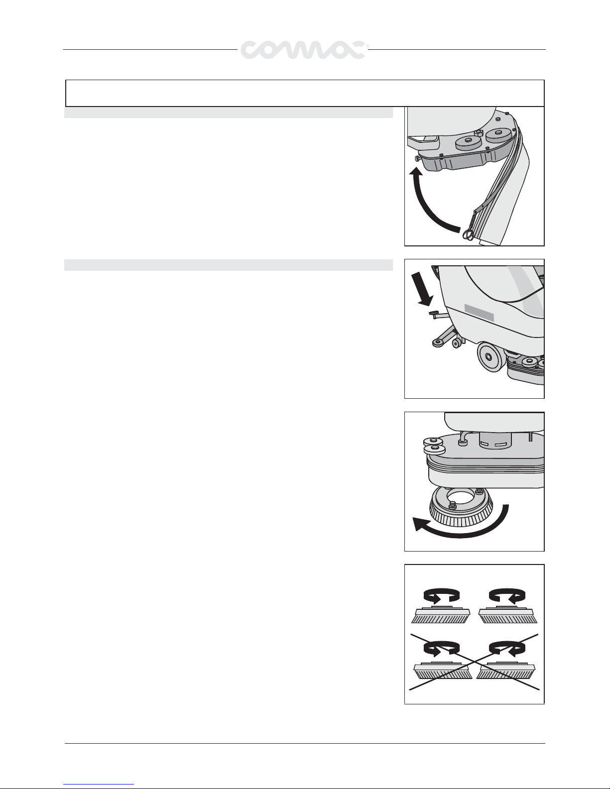
The splashguard is supplied separately from the machine, for packing reasons, and is to
be installed as shown in the picture.
INSTALLING THE BRUSH 42-52
INSTALLING THE BRUSH 42-52
INSTALLING THE BRUSH 42-52INSTALLING THE BRUSH 42-52
1. Lift the brush base by acting on the pedal.
2. Keeping the base lifted, thread the brushes on their seat on the hole under the base,
turning them until the three buttons enter the holes in the plate. Snap-shut the
button on the coupling spring to block it.
The picture shows the rotation direction just for the right brush: for the left one, turn
on the opposite direction.
We recommend to exchange daily the right brush with the left brush and vice versa. If
the brushes are not new, and their bristles are twisted, you would better reassemble
them in their original position, to avoid any overloads on the motor or excessive
vibrations.
31
Page 10
MACHINE PREPARATION
MACHINE PREPARATION
MACHINE PREPARATIONMACHINE PREPARATION
BRUSH ASSEMBLY ABILA 17
BRUSH ASSEMBLY ABILA 17
BRUSH ASSEMBLY ABILA 17BRUSH ASSEMBLY ABILA 17
1. Push the pedal in order to lift the brush base.
2. With lifted brush base try to bring the brushes in the right position corresponding to
the junctions of the machine.
3. Let the brush base down by acting on the pedal.
4. Press the operator present control lever (6) and the brush will be hooked
automatically.
5. In order to vary the advancement speed act upon the knob indicated in the
illustration.
6
32
Page 11

GENERAL SECURITY RULES
GENERAL SECURITY RULES
GENERAL SECURITY RULESGENERAL SECURITY RULES
Please carefully follow the listed below rules in order to avoid harm to the operator and damage to the machine:
Please carefully follow the listed below rules in order to avoid harm to the operator and damage to the machine:
Please carefully follow the listed below rules in order to avoid harm to the operator and damage to the machine:Please carefully follow the listed below rules in order to avoid harm to the operator and damage to the machine:
r
Read the labels on the machine carefully. Never cover them for any reason and always immediately replace them if they are
damaged
r
The machine is to be used only by authorised and trained staff
Pay attention to other people and particularly to children while the machine is working
r
r
Never mix different types of detergents: this could generate noxious gases
Never sets containers of liquids on the machine
r
Machine storage temperature must be between -25°C and +55°C
r
Operating conditions: room temperature between 0°C and +40°C with respective humidity between 30 and 95
r
r
Never use the machine in an explosive environment
Never use the machine to transport goods
r
Never use acid solutions, which could damage people or the machine
r
Avoid running the brushes with the machine stopped: this could damage the floor
r
r
Never aspirate flammable liquids
This appliance is not suitable for picking up hazardous dust
r
Use a powder fire extinguisher in case of fire. Do not use water
r
Do not hit against shelving or scaffolding when there is a danger of falling objects
r
r
Suit operating speed to traction conditions
Do not exceed over the limit gradient stated on the machine plate, to avoid conditions of instability
r
The machine must perform washing and drying operations simultaneously. Any other operations must be done in zones
r
where the presence of unauthorised persons is prohibited. Signal wet floor with suitable signs
r
Whenever the machine has operating troubles check to make sure these are not due to insufficient ordinary maintenance
Should not it be the case, enquire with your nearest COMAC
r
When replacing machine parts, always ask for ORIGINAL COMAC spare parts from your authorised agent and/or retailer
Use only original COMAC
r
r
Always cut out the electric power supply to the machine whenever maintenance is performed
ATTENTION: Restore all electrical connections after any maintenance operation
r
Never remove guards that require tools for removal
r
Never wash the machine with direct pressurised jets of water or with corrosive substances
r
r
Have your nearest COMAC
To avoid encrustation’s on the solution tank filter, do not fill it with the detergent solutions many hours before using the
r
machine
r
Before using the machine, make sure that all the doors and coverings are positioned as shown in this use and maintenance
booklet
Check that the recovery tank is empty before removing it
r
Carry off consumption materials according to the laws in force
r
When, after years of precious work your COMAC
r
composing materials, in particular oils, batteries and electronics components. Please remember that the machine has been
built using totally recyclable materials
COMAC brushes indicated in the paragraph “CHOICE AND USE OF BRUSHES”
COMACCOMAC
COMAC service centre checks the machine every 200 operating hours
COMACCOMAC
COMAC machine will be ready to be “pensioned”, organise the carrying off of its
COMACCOMAC
COMAC assistance centre
COMACCOMAC
33
Page 12
WORK PREPARATION
WORK PREPARATION
WORK PREPARATIONWORK PREPARATION
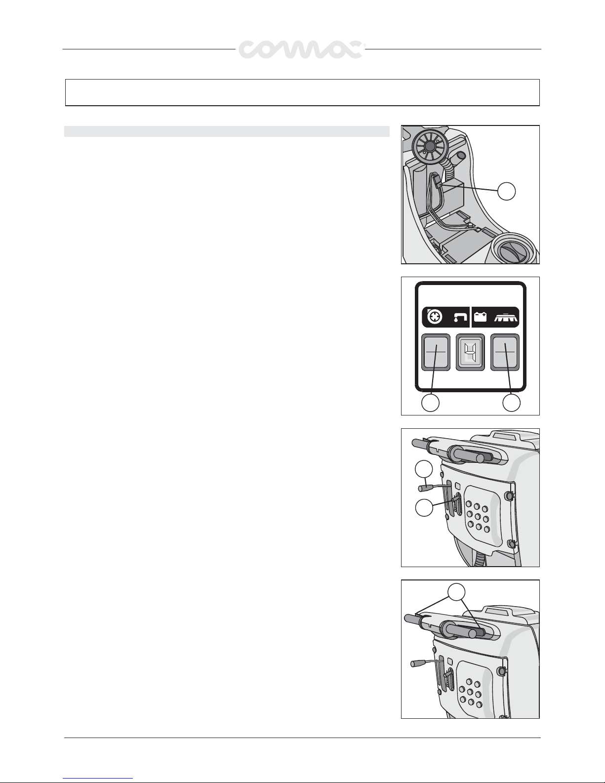
1. Connect the connector (1) to the battery
2. Press the brush switch (2)
3. Press the suction switch (3)
WORK
WORK
WORKWORK
1
4. Act on the cock lever (4) to adjust the detergent solution quantity: it should be
enough to regularly wet the floor but not as much as to flow out the splashguard.
Please not the right solution quantity depends on floor type, on dirt importance and
on speed.
5. Release the pedal and let the base lower.
6. Lower the squeegee acting on the lever (5).
7. Acting on the deadman lever (6) the brushes start turning and the squeegee starts
drawing in.
8. During the first few metres check that the amount of water is sufficient and that the
squeegee dries the floor perfectly.
3 2
5
4
6
34
Page 13
WORK
WORK
WORKWORK
OVERFLOW DEVICE
OVERFLOW DEVICE
OVERFLOW DEVICE OVERFLOW DEVICE
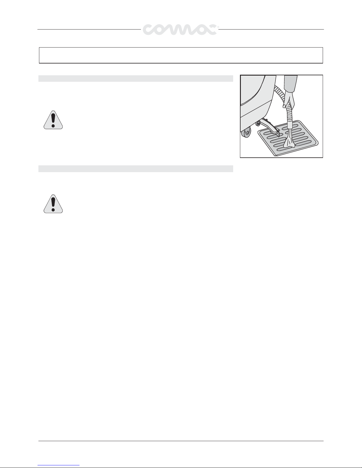
The machine is supplied with float that trips whenever the recovery tank is full, closing
the suction tube. In this case you should empty the recovery tank by removing the
outlet pipe cap.
ATTENTION!
ATTENTION! Always wear gloves during this procedure, to avoid any
ATTENTION! ATTENTION!
contact with dangerous substances.
TRACTION
TRACTION
TRACTION TRACTION
The brush obtains the traction of this machine: its inclination while working allows
dragging the machine along.
ATTENTION!
ATTENTION! While going into reverse, even briefly, make sure that the
ATTENTION!ATTENTION!
squeegee is lifted.
35
Page 14
UPON COMPLETION OF WORK
UPON COMPLETION OF WORK
UPON COMPLETION OF WORKUPON COMPLETION OF WORK
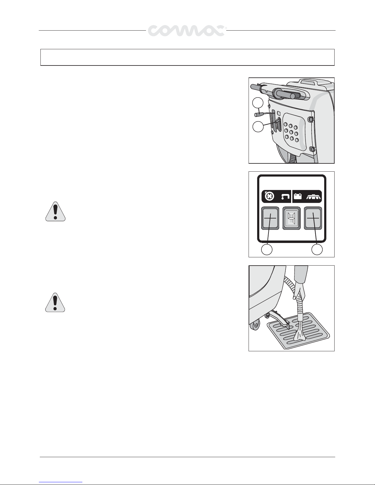
At the end of the work, and before performing any type of maintenance:
1. Close the cock by lever (1).
2. Raise base by pedal.
3. Raise squeegee by lever (2)
4. Turn off the brush switch (3).
5. Turn off suction motor switch (4).
ATTENTION!
ATTENTION! If after having switched off the brush switch (3) the display
ATTENTION! ATTENTION!
of the battery indicator remains on, this means that, the solution cock is
open. Close the water cock through the lever (1) in order to avoid leakage
of the detergent solution.
6. Move the machine to the water disposal point.
7. Hold the pipe placed on the back of the machine.
8. Remove the outlet cap and empty the tank.
2
1
4
3
ATTENTION!
ATTENTION! Always wear gloves during this procedure to avoid any
ATTENTION!ATTENTION!
contact with dangerous substances.
9. Disassembly the brush and clean it by a jet of water (for the disassembly of the
brush see the following “DISASSEMBLY OF THE BRUSH”)
36
Page 15
RECOVERY TANK CLEANING
RECOVERY TANK CLEANING
RECOVERY TANK CLEANINGRECOVERY TANK CLEANING
Hold the recovery tank outlet pipe.
1.
2.
Remove the outlet cap and empty the tank.
ATTENTION!
ATTENTION! Always wear gloves during this procedure, to avoid any
ATTENTION!ATTENTION!
contact with dangerous substances.
DAILY MAINTENANCE
DAILY MAINTENANCE
DAILY MAINTENANCEDAILY MAINTENANCE
3. Lift the recovery tank lid.
4.
Remove the suction cap (1) turning it anticlockwise.
Remove the filter and its protection.
5.
6.
Rinse the tank with a jet of water.
SUCTION FILTER CLEANING
SUCTION FILTER CLEANING
SUCTION FILTER CLEANINGSUCTION FILTER CLEANING
1.
Lift the lid.
2.
Remove the suction cap turning in anticlockwise.
Remove the filter.
3.
4.
Clean the filter walls and bottom by a jet of water.
5.
Carry out the cleaning procedures very carefully.
6.
Reassemble everything.
1
SQUEEGEE CLEANING
SQUEEGEE CLEANING
SQUEEGEE CLEANINGSQUEEGEE CLEANING
The squeegee must be in perfect working condition to achieve a good drying process.
Proceed as follows to clean it:
1.
Remove the pipe from the squeegee.
Loose the knobs (1) shown in picture.
2.
3.
Remove the mouth and clean it.
4.
Carefully clean the inside of the squeegee.
5.
Carefully clean the squeegee rubbers.
Reassemble everything.
6.
1
37
Page 16
DAILY MAINTENANCE
DAILY MAINTENANCE
DAILY MAINTENANCEDAILY MAINTENANCE
BRUSHES DISASSEMBLY ABILA 42 52
BRUSHES DISASSEMBLY ABILA 42 52
BRUSHES DISASSEMBLY ABILA 42 52BRUSHES DISASSEMBLY ABILA 42 52
Push lever down to raise the base.
1.
2.
Turn key to OFF and remove it from the control panel (1)
WARNING!
WARNING! Removing the brushes with power on may cause
WARNING! WARNING!
injury to the hands.
3. Rotate the brush, with base raised, until it exits form the brush-bearing plate as
shown in the picture. The picture shows the direction of rotation for releasing the
right brush. Rotate in opposite direction for the left brush.
ATTENTION!
ATTENTION! Make sure that no persons or object are nearby the brush
ATTENTION! ATTENTION!
during this operation.
1
BRUSHES DISASSEMBLY ABILA 17
BRUSHES DISASSEMBLY ABILA 17
BRUSHES DISASSEMBLY ABILA 17BRUSHES DISASSEMBLY ABILA 17
1.
Lift the brush base through the pedal (push down).
With brush base in lifted position operate the operator control lever, and the brush
2.
will unhook automatically.
CLEANING SOLUTION FILTER
CLEANING SOLUTION FILTER
CLEANING SOLUTION FILTERCLEANING SOLUTION FILTER
1.
Take off the filter on the solution tank
Clean it thoroughly
2.
3.
Reassemble everything
ATTENTION!
ATTENTION! Always wear gloves during this procedure, to avoid any
ATTENTION!ATTENTION!
contact with dangerous substances.
38
Page 17
WEEKLY MAINTENANCE
WEEKLY MAINTENANCE
WEEKLY MAINTENANCEWEEKLY MAINTENANCE
CLEANING SQUEEGEE HOSE
CLEANING SQUEEGEE HOSE
CLEANING SQUEEGEE HOSECLEANING SQUEEGEE HOSE
Weekly, or whenever the suction in insufficient, it is necessary to check that the
squeegee pipe is not obstructed. Should it be the case, proceed as follows to clean it:
1. Unthread the pipe from the squeegee sleeve.
2. Unthread the other end from the recovery tank.
3. Wash the inside of pipe by a jet of water, from the side it is plug to the tank.
4. To reassemble the pipe repeat the above-mentioned operations.
ATTENTION!
ATTENTION! Do not wash the pipe connecting the aspirator to the suction
ATTENTION!ATTENTION!
cap.
CLEANING SOLUTION TANK
CLEANING SOLUTION TANK
CLEANING SOLUTION TANKCLEANING SOLUTION TANK
1. Remove the cap from the solution tank.
2. Rinse with a jet of water.
3. Remove the outlet cap (1) and empty the tank
ATTENTION!
ATTENTION! Always wear gloves during this procedure, to avoid any
ATTENTION!ATTENTION!
contact with dangerous substances.
REAR SQUEEGEE RUBBERS REPLACEMENT
REAR SQUEEGEE RUBBERS REPLACEMENT
REAR SQUEEGEE RUBBERS REPLACEMENTREAR SQUEEGEE RUBBERS REPLACEMENT
Check the squeegee rubbers wear and replace them if necessary.
Proceed as follows
1.
Unthread the squeegee pipe from sleeve.
2.
Remove the pin from column.
3.
Remove the squeegee from its support.
Loosen the wing nuts (1) blocking the rubber blades and take them off.
4.
5.
Replace the rubbers
To reassemble the squeegee repeat the above-mentioned operations.
1
1
39
Page 18
WORKING CONTROL
WORKING CONTROL
WORKING CONTROLWORKING CONTROL
INSUFFICIENT WATER TO THE BRUSHES
INSUFFICIENT WATER TO THE BRUSHES
INSUFFICIENT WATER TO THE BRUSHESINSUFFICIENT WATER TO THE BRUSHES
1. Check that the cock (1) is open.
2. Check that there is water in the solution tank.
THE MACHINE DOES NOT CLEAN PROPERLY
THE MACHINE DOES NOT CLEAN PROPERLY
THE MACHINE DOES NOT CLEAN PROPERLYTHE MACHINE DOES NOT CLEAN PROPERLY
1. Check the brushes wear and replace them if necessary (the brushes must be
replaced when bristles are 15 mm high).
To replace brushes see “BRUSHES DISASSEMBLY” and ”BRUSH ASSEMBLY”.
2. Use another type of brush rather than the standard brush. We recommend, for
cleaning exceptionally difficult dirt floors, the use of special brushes, supplied on
request and according to your specific needs (see “CHOICE AND USE OF
BRUSHES”).
1
THE SQUEEGEE DOES NOT DRY PERFECTLY
THE SQUEEGEE DOES NOT DRY PERFECTLY
THE SQUEEGEE DOES NOT DRY PERFECTLYTHE SQUEEGEE DOES NOT DRY PERFECTLY
1. Check that the squeegee rubbers are clean
2. Adjust the squeegee inclination (see “SQUEEGEE” in “PREPARING THE MACHINE”)
3. Check that the suction pipe is correctly housed in its seat on the recovery tank.
4. Remove the whole suction unit and clean it.
5. Replace the rubbers if worn.
6. Check that the suction motor switch is turn on.
7. Check the wheels regulation.
FOAM OVER-FORMATION
FOAM OVER-FORMATION
FOAM OVER-FORMATIONFOAM OVER-FORMATION
Check that low-foam detergent is used. Add, if necessary, a small quantity of anti-foam
liquid to recovery tank.
Please remember that more foam is generated when the floor to be cleaned it is not very
dirty. In this case use a more diluted detergent solution.
40
Page 19

CHOICE AND USE OF BRUSHES
CHOICE AND USE OF BRUSHES
CHOICE AND USE OF BRUSHESCHOICE AND USE OF BRUSHES
POLYPROPYLENE BRUSH (PPL)
POLYPROPYLENE BRUSH (PPL)
POLYPROPYLENE BRUSH (PPL)POLYPROPYLENE BRUSH (PPL)
It is used on all floor types and offers good resistance to wear and to hot water (not over 60
°C). PPL is not hygroscopic, then
preserves its characteristics even when working on wet floors.
NYLON BRUSH
NYLON BRUSH
NYLON BRUSHNYLON BRUSH
It is used on all floor types and offers excellent resistance to wear and to hot water (60
°C and over). Nylon is hygroscopic and
tends, over a period of time, to loose its characteristics when working on wet floors.
ABRASIVE BRUSH
ABRASIVE BRUSH
ABRASIVE BRUSHABRASIVE BRUSH
This brush bristles are impregnated with highly aggressive abrasives. This brush is use to clean very dirty floors. We recommend
using only the minimum necessary bare pressure to prevent damages to the floor.
BRISTLES THICKNESS
BRISTLES THICKNESS
BRISTLES THICKNESSBRISTLES THICKNESS
Thicker bristles are stiffer and should be used on smooth floors with narrow joints between tiles.
We recommend using softer bristles when floors are uneven or have deep joints or raised edges. Softer bristles penetrate easier
into joints.
Remember that when brush bristles are worn and become too short they become stiffer and are no longer able to penetrate in
depth. This is also because, as when using bristles that are too big, the brush tends to jump and skip.
PAD HOLDER
PAD HOLDER
PAD HOLDERPAD HOLDER
Pad holder is recommended for cleaning polished surfaces.
There are two types of pad holders:
1.
Traditional pad holders with set of anchor stubs that retain and drive the abrasive disk during operation.
CENTER LOCK pad holders which, in addition to anchor stubs, also have a plastic snap-in centre lock system. This permits
perfect centring of the abrasive disk and ensures it is kept anchored without detaching. This type of pad holder is best for
machines with several brushes, where it is difficult to centre the abrasive disks.
LIST FOR THE CHOICE OF THE BRUSHES
LIST FOR THE CHOICE OF THE BRUSHES
LIST FOR THE CHOICE OF THE BRUSHESLIST FOR THE CHOICE OF THE BRUSHES
Machine
Machine
MachineMachine
ABILA 17 1
ABILA 42 2
ABILA 52 2
NNNN°°°° Brushes
Brushes
Brushes Brushes
Code
Code Bristles type
CodeCode
66824010
66824020
66824030
66824040
66724010
66724020
66805020
66805050
66805060
66805120
66705020
66724030
66808010
66808040
66808020
66808030
66708010
Bristles type
Bristles typeBristles type
PPL
PPL
PPL
Abrasive
Pad holder h=40
Pad holder h=60
PPL
PPL
PPL
Abrasive
Pad holder
Pad holder
PPL
PPL
PPL
Abrasive
Pad holder
∅∅∅∅Bristles
Bristles ∅∅∅∅ Brushes
BristlesBristles
0.3
0.6
0.9
1
0.3
0.5
0.9
1
0.3
0.5
0.9
1
Brushes
Brushes Brushes
420
420
420
420
420
420
210
210
210
210
200
200 Trec System
255
255
255
255
245
Remarks
Remarks
RemarksRemarks
41
 Loading...