

Page 1
DOXport™ 1110 Cable Modem
User’s Guide
Page 2

Trademark Acknowledgment
Copyright © Com21, Inc. 2000.
Com21 is a registered trademark of Com21, Inc (“Com21”). The Com21 logo, DOXport,
and the Red Door Device are trademarks of Com21. All rights reserved. All other trade
names or trademarks are the property of their respective holders.
The purchase and use of a Com21 product does not convey a license under any patent
rights, copyrights, trademark rights or any other intellectual property rights of Com21. All
rights reserved. Authorized customers of Com21 may print copies of this documentation
for internal use only. Except as expressly provided herein, no part of this documentation
may be reproduced, stored in a retrieval system, or transmitted, in any form or by any
means, electronic, mechanical, photocopying, or otherwise, without the prior written
permission of Com21.
Part Number: 271-0117-00
Printed in the U.S.A.
September 2000
ii DOXport 1110 User’s Guide
Page 3

Contact Information
If you need help installing your modem, you can contact Com21 by telephone or Internet:
Phone: 888-868-4154
Website: www.com21.com
Important Rules for Safe Operation
Please read and follow the instructions in this manual. Use the AC adapter that is provided
with the modem.
FCC Compliance
This DOCSIS cable modem has been tested and found to comply with the limits for a Class B
personal computer and peripherals, pursuant to Part 15 of the FCC Rules. These limits are
designed to provide reasonable protection against harmful interference in a residential
installation. This equipment generates, uses, and can radiate radio frequency energy and, if not
installed and used in accordance with the instructions, may cause harmful interference to radio
communications. There is no guarantee that interference will not occur in a particular
installation. If this unit does cause harmful interference to radio or television reception, which
can be determined by turning the unit off and on, the user is encouraged to try to correct the
interference by taking one or more of the following measures:
• Increase the distance between this unit and receiver.
• Connect this unit to a circuit that is isolated from the receiver circuit.
iii
Page 4

iv DOXport 1110 User’s Guide
Page 5

Table of Contents
Introduction . . . . . . . . . . . . . . . . . . . . . . . . . . . . . . . . . . . . . . . . . . . . . . . . . . . . . . . . . . . . 1
Your DOXport 1110 Cable Modem . . . . . . . . . . . . . . . . . . . . . . . . . . . . . . . . . . . . . 1
Package Contents . . . . . . . . . . . . . . . . . . . . . . . . . . . . . . . . . . . . . . . . . . . . . . . . . . . . 1
Before You Start . . . . . . . . . . . . . . . . . . . . . . . . . . . . . . . . . . . . . . . . . . . . . . . . . . . . . . . . 1
Installing the Cable Modem . . . . . . . . . . . . . . . . . . . . . . . . . . . . . . . . . . . . . . . . . . . . . . . 2
Configuring TCP/IP . . . . . . . . . . . . . . . . . . . . . . . . . . . . . . . . . . . . . . . . . . . . . . . . . . . . . 9
Verifying Your IP Address . . . . . . . . . . . . . . . . . . . . . . . . . . . . . . . . . . . . . . . . . . . 12
Diagnostics . . . . . . . . . . . . . . . . . . . . . . . . . . . . . . . . . . . . . . . . . . . . . . . . . . . . . . . . . . . . 13
LED Identification . . . . . . . . . . . . . . . . . . . . . . . . . . . . . . . . . . . . . . . . . . . . . . . . . . 13
LED Acquisition States . . . . . . . . . . . . . . . . . . . . . . . . . . . . . . . . . . . . . . . . . . . . . . 13
Troubleshooting with LEDs . . . . . . . . . . . . . . . . . . . . . . . . . . . . . . . . . . . . . . . . . . 15
Checking the USB Driver . . . . . . . . . . . . . . . . . . . . . . . . . . . . . . . . . . . . . . . . . . . . 16
DOXport 1110 Specifications . . . . . . . . . . . . . . . . . . . . . . . . . . . . . . . . . . . . . . . . . . . . . 19
Reliance Fundamentals
Ta b l e o f C o n t e n t s v
Page 6

vi DOXport 1110 User’s Guide
Page 7

List of Tables
Table 1. DOXport 1110 Rear Panel Ports .......................................................................................2
Table 2. DOXport 1110 LEDs........................................................................................................13
Table 3. LED Troubleshooting .......................................................................................................15
Table 4. Specifications .......................................................................................................................19
Reliance Fundamentals
List of Tables ix
Page 8

x DOXport 1110 User’s Guide
Page 9

List of Figures
Figure 1. Package Contents ................................................................................................................1
Figure 2. DOXport 1110 with Detachable Stand ...........................................................................2
Figure 3. Rear Panel Ports ..................................................................................................................2
Figure 4. Cabling Diagram with Ethernet Configuration ..............................................................4
Figure 5. Cabling Diagram with USB Configuration .....................................................................5
Figure 6. USB Driver Self-Install.......................................................................................................5
Figure 7. Add New Hardware Wizard ..............................................................................................6
Figure 8. Search for Best Driver ........................................................................................................7
Figure 9. Select CD-ROM Drive .......................................................................................................7
Figure 10. Install USB Driver.............................................................................................................8
Figure 11. Finish Installing USB Driver ...........................................................................................8
Figure 12. Network Window..............................................................................................................9
Figure 13. Select Network Component Type Window................................................................10
Figure 14. Select Network Protocol Window................................................................................10
Figure 15. Network Window............................................................................................................11
Figure 16. TCP/IP Properties Window .........................................................................................11
Figure 17. Verifying IP Address ......................................................................................................12
Figure 18. LED states........................................................................................................................14
Figure 19. Device Manager...............................................................................................................16
Figure 20. USB Device with Warning Symbol ..............................................................................17
Figure 21. Removing USB Driver ...................................................................................................18
Reliance Fundamentals
List of Figures vii
Page 10

viii DOXport 1110 User’s Guide
Page 11
Introduction
Your DOXport 1110 Cable Modem
Your DOXport 1110 cable modem gives you high-speed, always on access to the Internet
through your cable TV (CATV) network. The DOXport 1110 works on any cable system that
complies with the Data Over Cable Services Interface Specifications (DOCSIS).
Package Contents
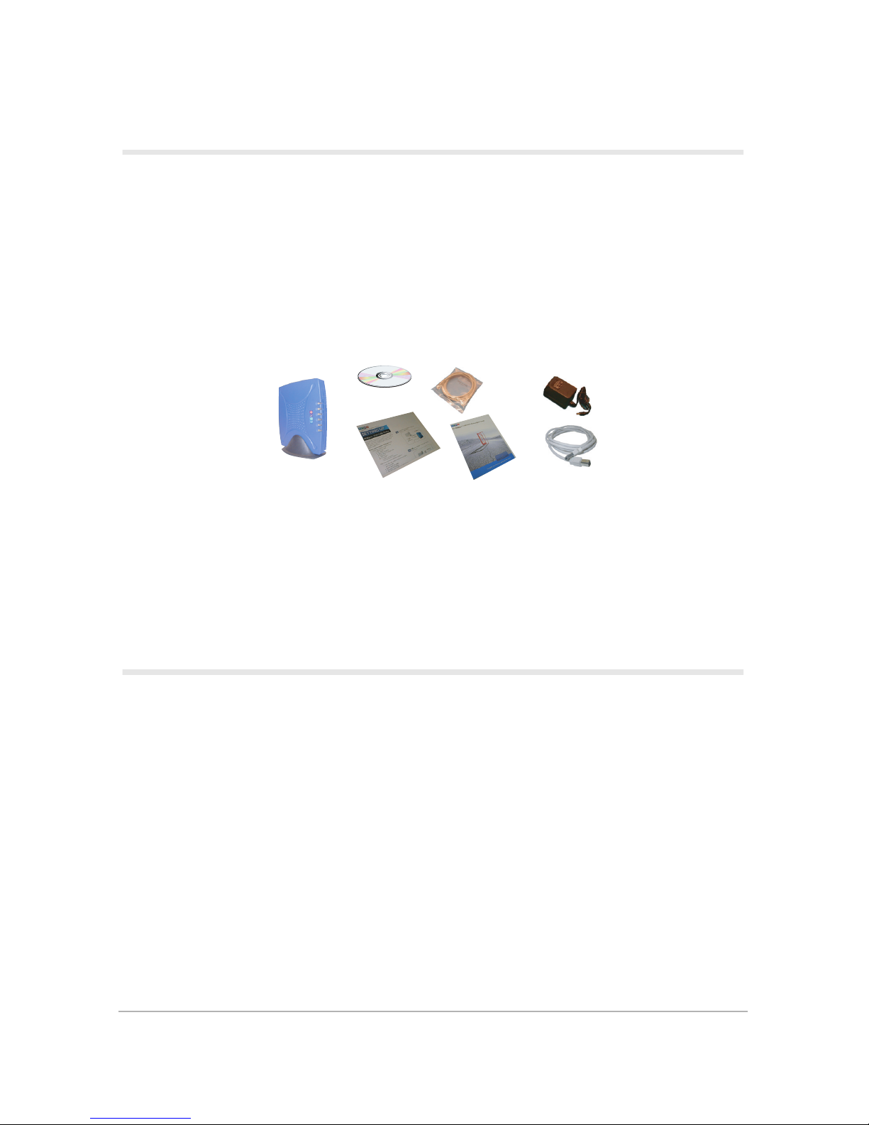
Check the contents of the package. It should contain the items shown in Figure 1.
AC
Adapter
A00247
CD-ROM
Ethernet
Cable
DOXport 1110
Modem
with Stand
Figure 1.
Setup
Sheet
User's Guide
Package Contents
USB Cable
Please contact the place of purchase if any of the above listed items are missing or damaged. If
your cable modem was obtained directly from your cable operator, it may have been bulk
packaged without the cables, setup sheet, and user’s guide.
Before You Start
Before you install your DOXport 1110, you need the following items. These items are not
supplied with the DOXport 1110.
1. DOCSIS cable modem service from your local service provider
2. CATV (cable TV) outlet
3. Two-way CATV splitter
4. Two RG6 coaxial cables; one cable connects the CATV outlet to the 2-way
splitter and the other cable connects one output of the splitter to your cable
modem
5. Computer with 10 Base-T Ethernet LAN port OR computer with functional
USB port running Windows 98/Me/2000
6. TCP/IP protocol stack
Introduction 1
Page 12
Installing the Cable Modem
Place your DOXport 1110 cable modem in an area that will not block any of its ventilation
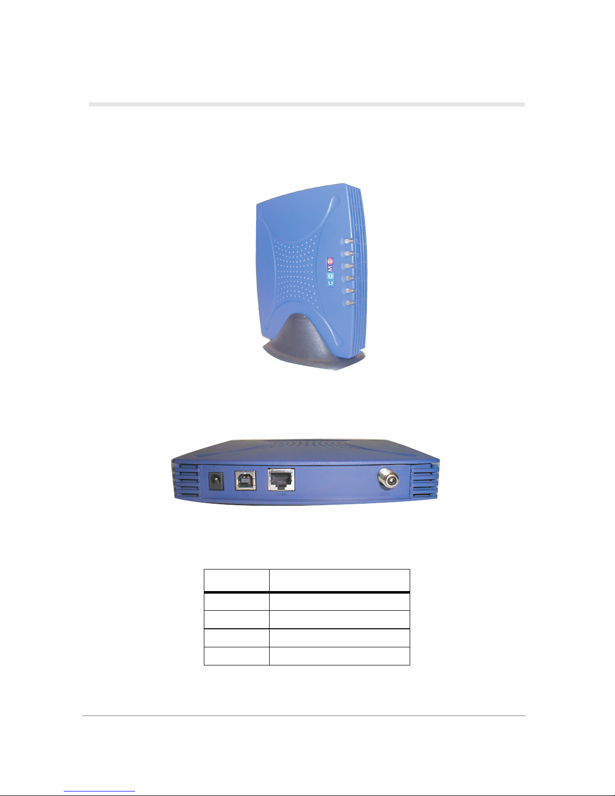
holes. In order to hold the modem in an upright position (as shown below), use the included
stand.
A00262
Figure 2.
DOXport 1110 with Detachable Stand
Figure 3 shows the rear panel ports for Ethernet, USB, Power, and RF (cable).
A00261
Figure 3.
Table 1:
DC 15VDC@1A input
USB USB 1.1 B-type connector
10/100 10/100 Base-T RJ45
CATV F-type coaxial connector
DOXport 1110 Rear Panel Ports
Port Interf ace
Rear Panel Ports
2 DOXport 1110 User’s Guide
Page 13

The setup sheet provided in your package and/or on the CD provides an illustrated step-bystep procedure for setting up your modem. To summarize:
1. Make sure all “Before you start” requirements are met.
2. Look at the label on the bottom of the cable modem. This label shows the serial
number, the MAC (Media Access Control) address of your cable modem, and
the MAC address of the USB port. These numbers are unique to your modem.
Write them in the spaces below; you may need them for installation and future
reference. The CATV network uses the MAC addresses to communicate with
your modem.
Serial number _________________________
Modem MAC address___________________
USB MAC address _____________________
3. Connect the cable TV outlet to the input connector of a two-way CATV splitter
using an RG6 coaxial cable.
4. Connect a coaxial cable from one of the output connectors of the splitter to the
CATV port on the cable modem rear panel. The other output connector on the
splitter may be connected to other devices, such as your television or VCR.
5. Connect your computer to the cable modem using the Ethernet or USB port.
If you use your computer’s Ethernet port:
a. Connect one end of the Ethernet cable to your computer’s Ethernet port.
b. Connect the other end of the Ethernet cable to the Ethernet port on the
modem (labeled “10/100”).
c. Connect the 15VDC power adapter to the power port on the cable modem
rear panel (labeled “DC”). Plug the adapter into a power outlet.
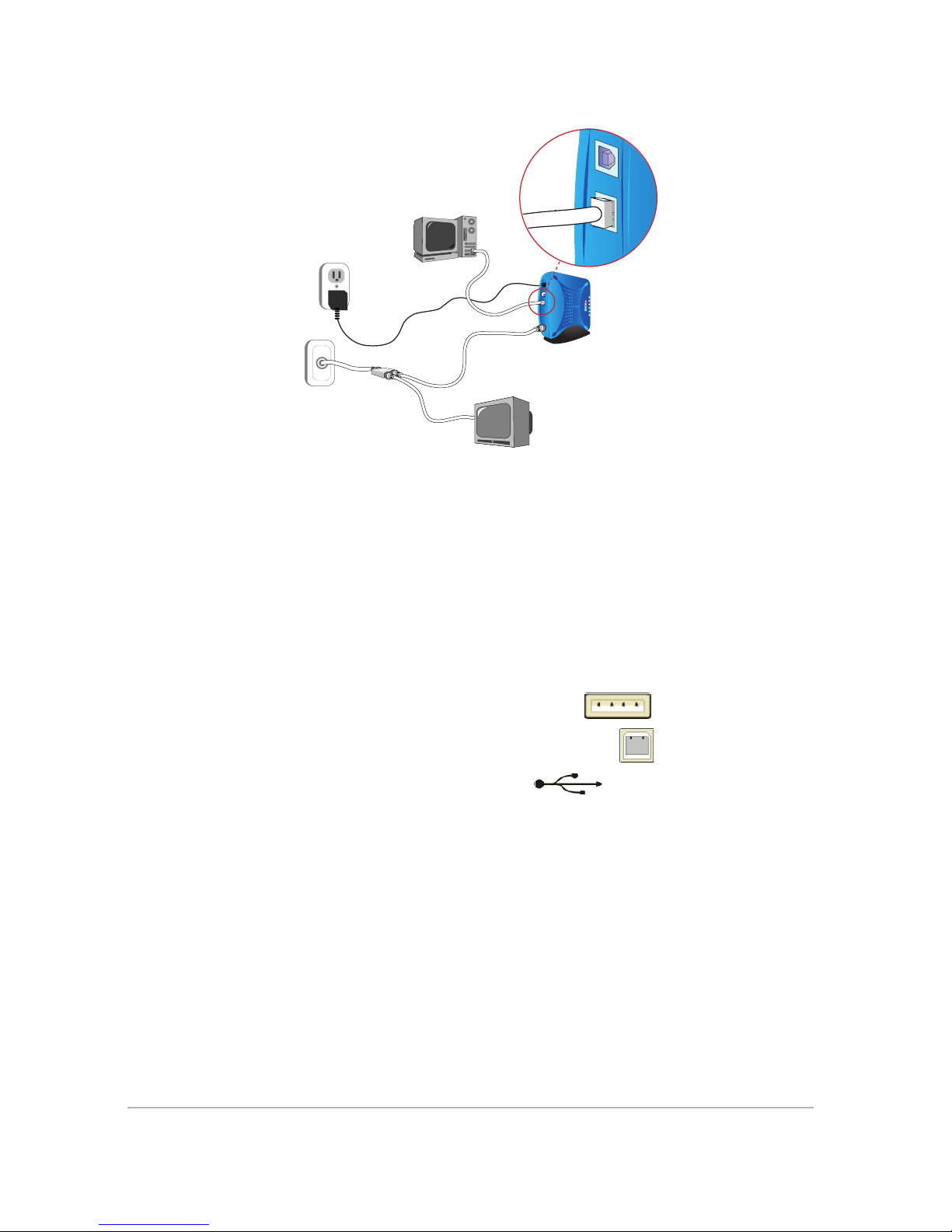
d. Your configuration should look like Figure 4.
Installing the Cable Modem 3
Page 14
PC with
Ethernet Card
10/100
USB
Wall Outlet
CATV
Outlet
Figure 4.
AC
Adapter
Coaxial
Cable
Cable TV
Splitter
Cabling diagram with Ethernet Configuration
Ethernet
Cable
Television
DOXport 1110
Modem
A00250
e. Your modem will now begin the auto-acquisition process. Refer to “LED
Acquisition States” on page 13.
f. Go to step 6 on page 9.
If you use your Windows 98/Me/2000 computer’s USB port (self-install
procedure):
The self-install procedure is recommended; the manual install procedure (refer to
page 6) is for an advanced user.
a. Plug the rectangular-end of the USB cable into your computer’s
USB port, and the square-end of the USB cable
the DOXport 1110 (labeled “USB”
).
into the USB port of
b. Your configuration should look like Figure 5.
4 DOXport 1110 User’s Guide
Page 15
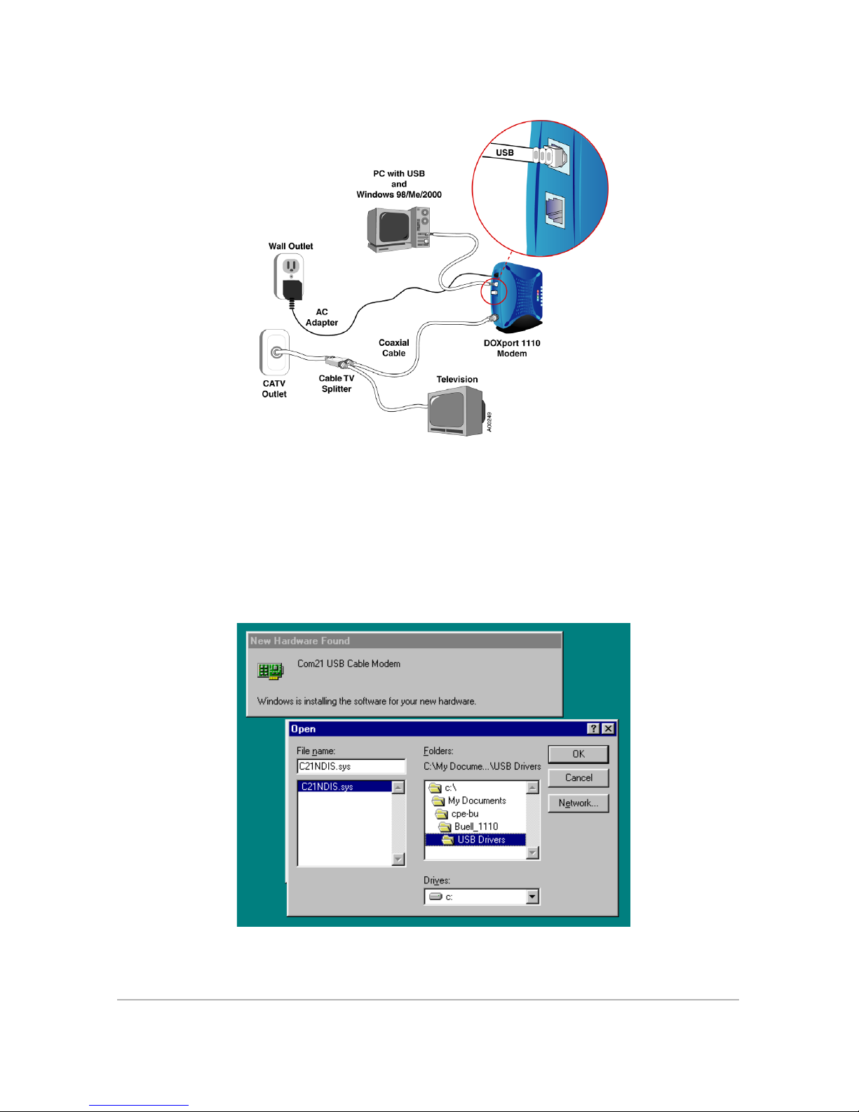
Figure 5.
Cabling Diagram with USB Configuration
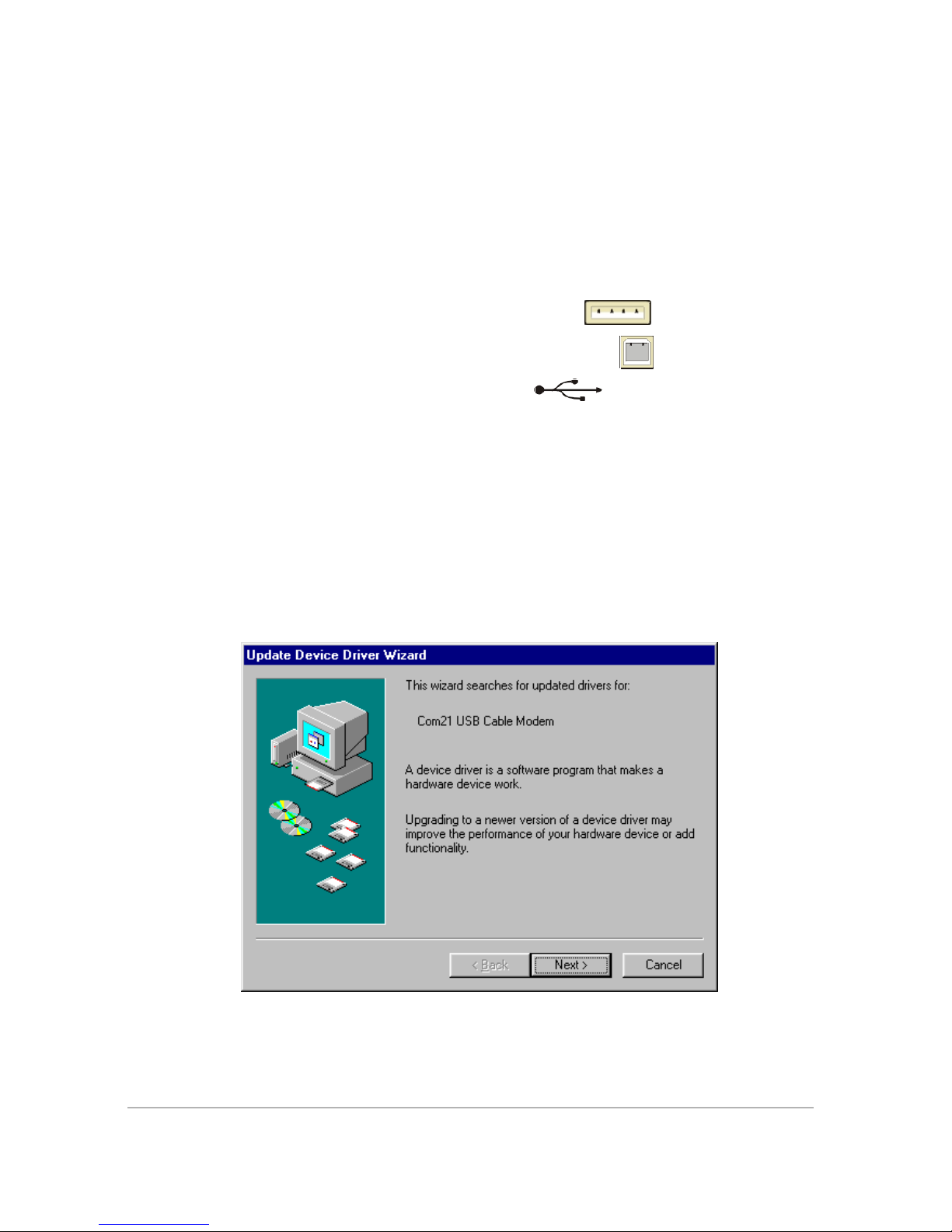
c. Once the USB cable is connected between the DOXport 1110 and the PC,
the computer will detect the newly added USB device and install the
necessary drivers automatically. (The DOXport 1110 USB drivers are
stored in the Reference CD, so make sure the CD is in the computer CDROM drive. If prompted, enter the drive letter of the CD-ROM).
d. Follow the on-screen prompts to finish the USB driver installation.
Figure 6.
USB Driver Self-Install
Installing the Cable Modem 5
Page 16
e. Reboot the computer when the installation is finished.
— Click START -> SHUT DOWN -> RESTART.
f. Your modem will now begin the auto-acquisition process. Refer to “LED
Acquisition States” on page 13.
g. Go to step 6 on page 9.
Using your Windows 98/Me/2000 computer’s USB port (manual procedure):
a. Plug the rectangular-end of the USB cable into your computer’s
USB port, and the square-end of the USB cable
the DOXport 1110 (labeled “USB”
).
into the USB port of
b. Once the USB cable is connected, the computer will detect the newly
added USB device and prompt for the USB driver installation. Click OK
to begin the installation.
c. Follow the on-screen prompt instructions and enter the drive letter of the
DOXport 1110 Reference CD-ROM, on which the USB device driver and
support driver are located.
d. After the networking device driver is installed, the networking support
driver is also needed. Follow the on-screen prompt to complete the
installation.
e. Click Next to the next prompt
6 DOXport 1110 User’s Guide
Figure 7.
o
Add New Hardware Wizard
Page 17
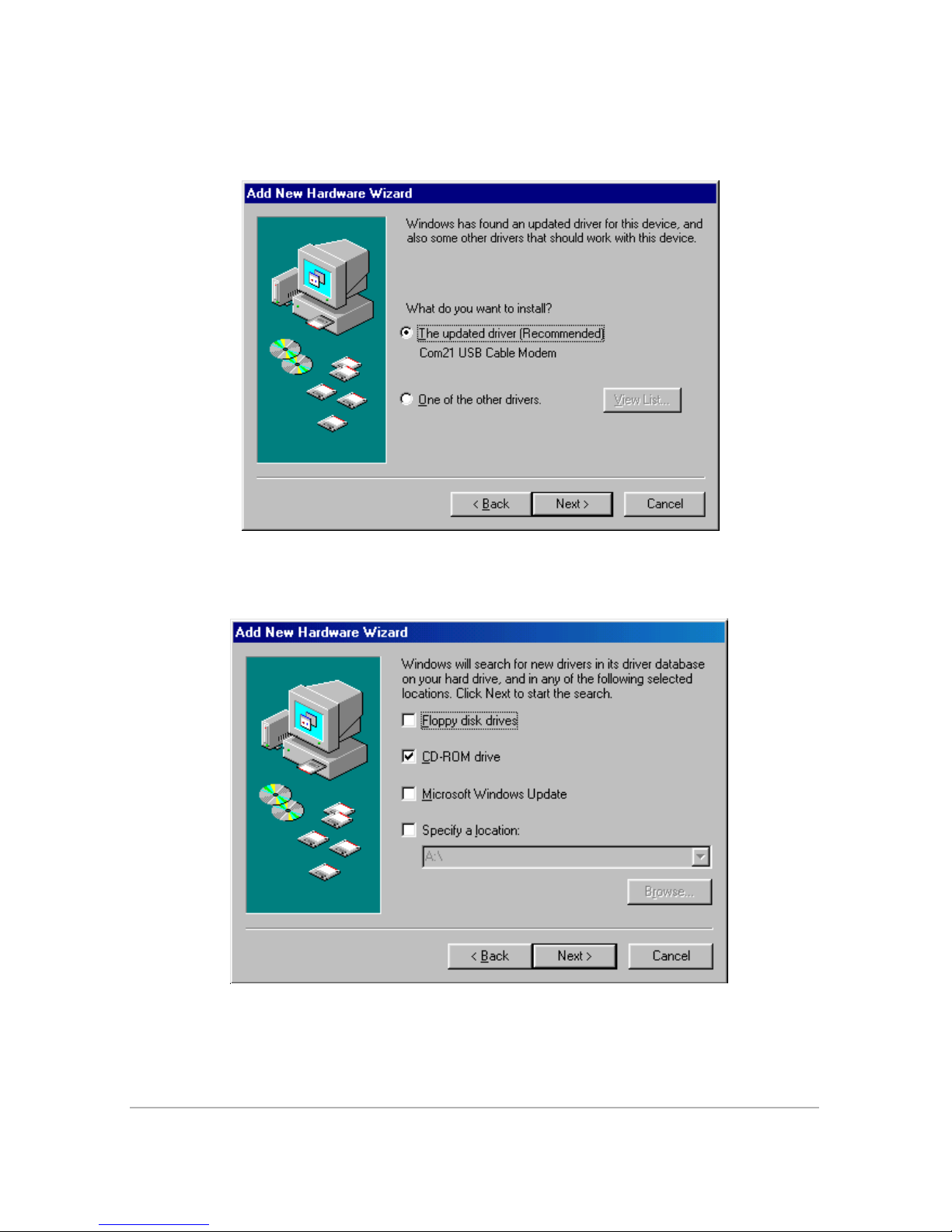
f. Select the recommended option ‘Search for the best drivers for your
device’, then click Next.
Figure 8.
Search for Best Driver
g. Select CD-ROM drive, in which the drivers are stored, then click Next.
[
Installing the Cable Modem 7
Figure 9.
Select CD-ROM Drive
Page 18
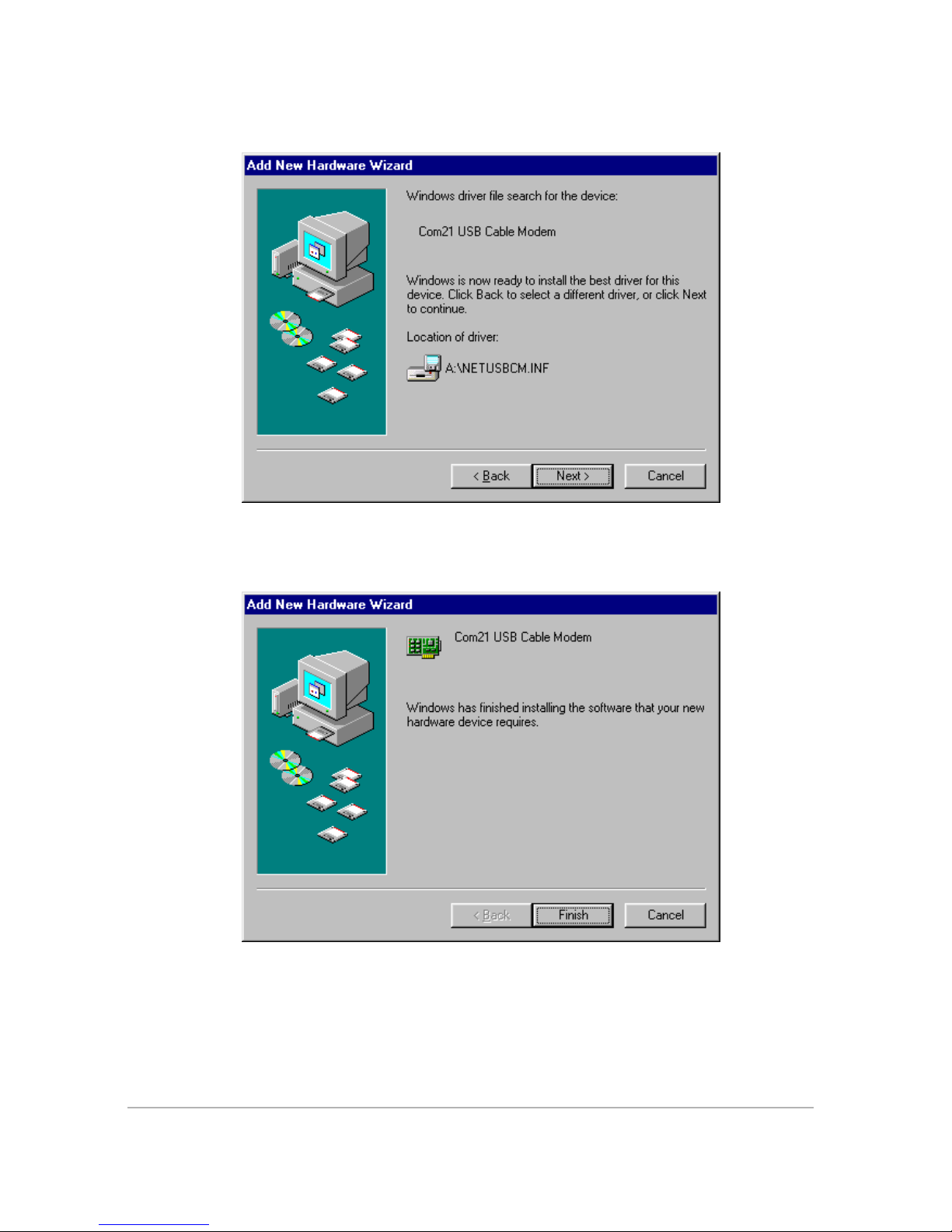
h. The computer will display the device driver it found. Click Next.
Figure 10.
Install USB Driver
i. Click Finish to complete the installation.
Figure 11.
Finish Installing USB Driver
j. Reboot the computer when the installation is finished.
— Click START -> SHUT DOWN -> RESTART
8 DOXport 1110 User’s Guide
Page 19

k. Your modem will now begin the auto-acquisition process. Refer to “LED
Acquisition States” on page 13 for details.
Now that you have connected the PC and the DOXport 1110, perform the
following step:
6. Configure the network parameters of your computer based on the instructions
provided by your cable operator. Refer to “Configuring TCP/IP” on page 9 and
“Verifying Your IP Address” on page 12 for information on how to configure
TCP/IP and check your IP address in Windows.
Configuring TCP/IP
With the modem connected, make sure that you have your computer configured for TCP/IP
and check for an IP address. The following instructions are for Windows 98 using Ethernet. If
you are using a different operating system, or computer interface, refer to that system’s user’s
guide.
Perform the following steps:
1. On the Windows desktop, click Start.
2. Select Settings and then Control Panel from the pop-up menu. Double-click
the Network icon on the Control Panel window. The Network window
appears, as shown in Figure 12.
Configuring TCP/IP 9
Figure 12.
Network Window
Page 20
3. Select the Configuration tab on the Network window.
4. Check to see if TCP/IP has been installed for the Ethernet card. If TCP/IP
appears in the list of network components, it is installed. Select it and proceed
to step 8. If it doesn't appear on the list, click Add and continue with step 5.
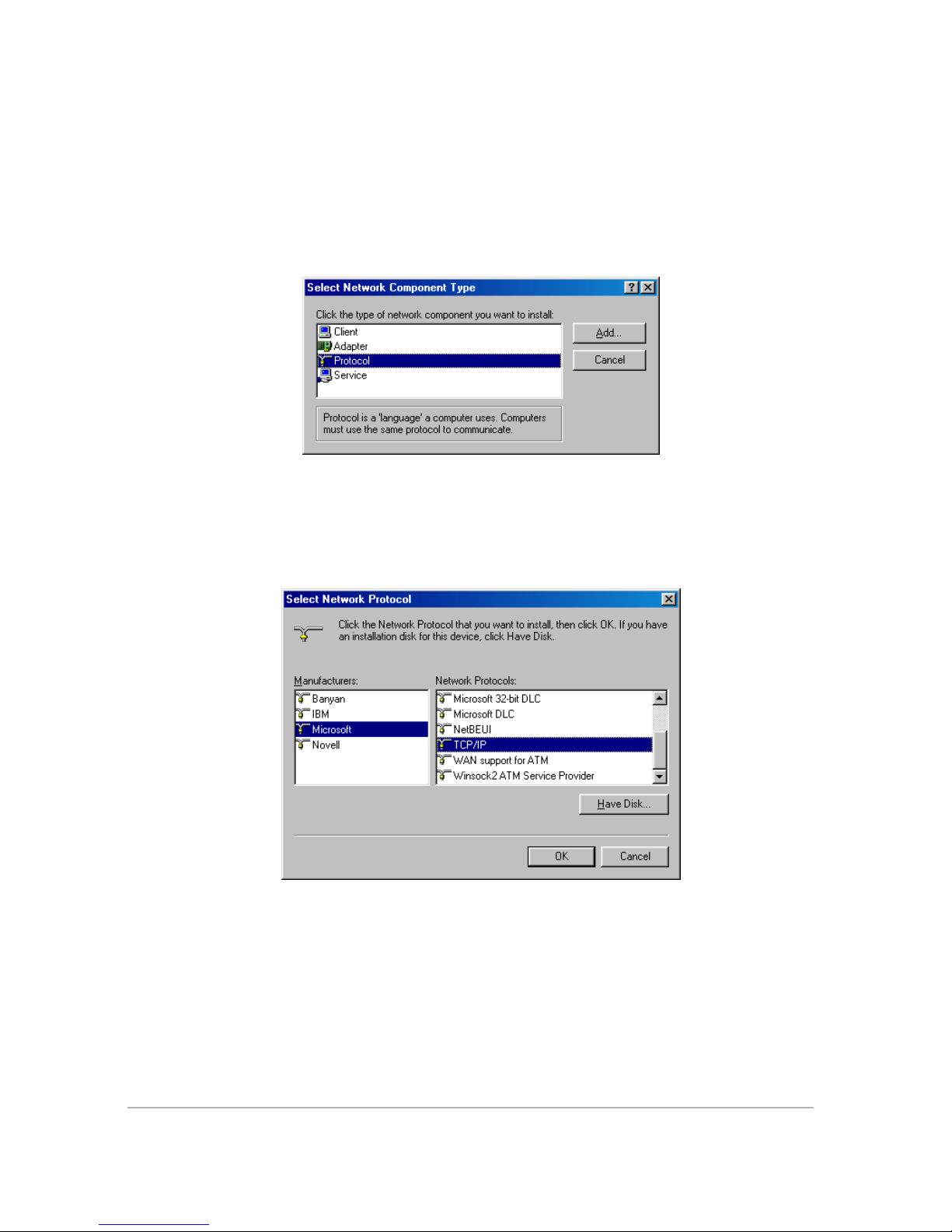
5. Double-click the PROTOCOL option on the SELECT NETWORK
COMPONENT TYPE window (Figure 13).
Figure 13.
Select Network Component Type Window
6. Click MICROSOFT in the MANUFACTURERS section and then click
TCP/IP in the NETWORK PROTOCOL section on the SELECT
NETWORK PROTOCOL window (Figure 14).
Figure 14.
Select Network Protocol Window
7. Click OK.
10 DOXport 1110 User’s Guide
Page 21
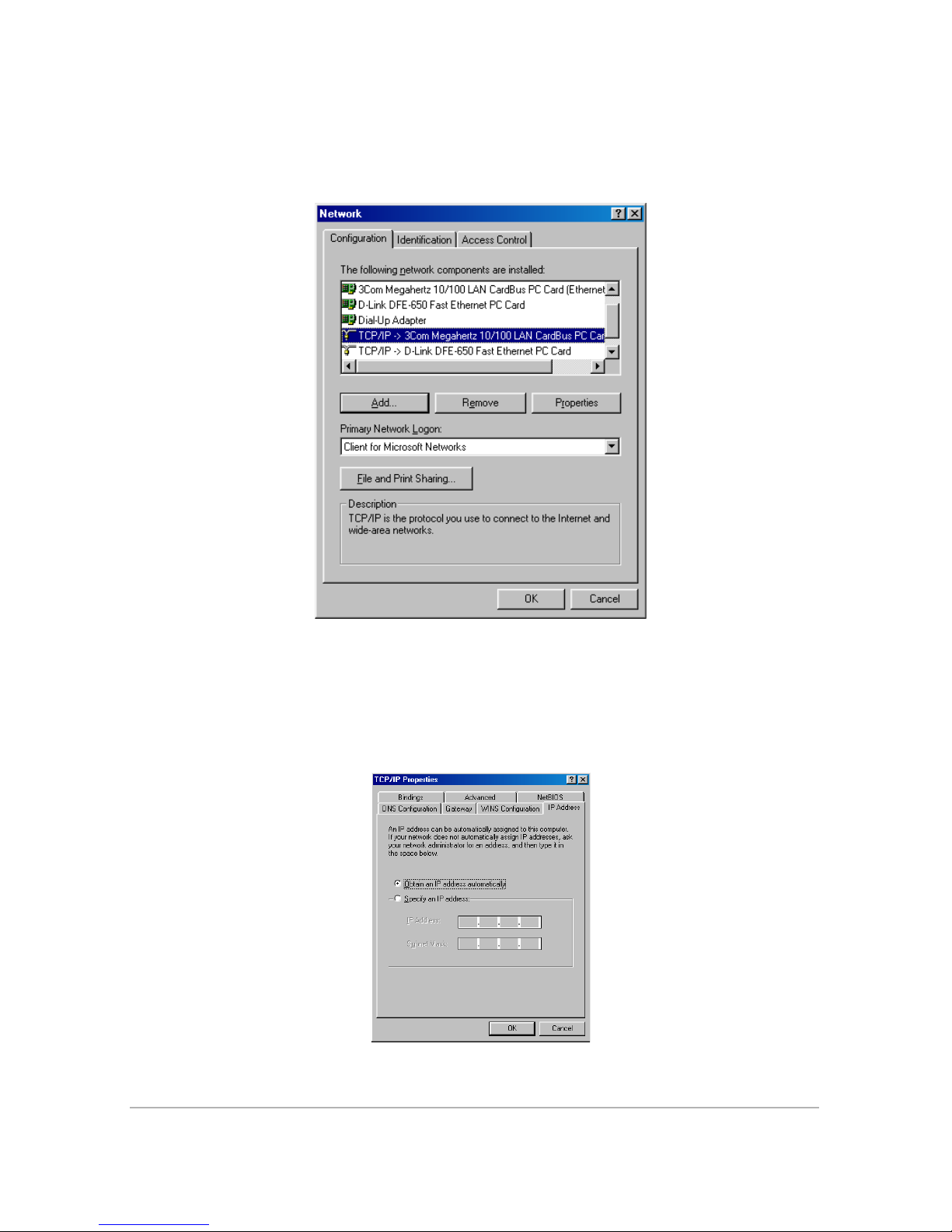
8. Click TCP/IP on the NETWORK window (Figure 15). If you have more than
one TCP/IP entry, choose the one associated with the Ethernet card connected
to the DOXport 1110.
Figure 15.
Network Window
9. Click PROPERTIES.
10. Select the IP ADDRESS tab on the TCP/IP PROPERTIES window (Figure
16).
Figure 16.
TCP/IP Properties Window
Configuring TCP/IP 11
Page 22
11. Click on OBTAIN AN IP ADDRESS AUTOMATICALLY.
12. Click OK to accept the TCP/IP settings.
13. Click OK to close the NETWORK window.
14. Click OK when a prompt to restart your computer is displayed, and then click
OK again.
Verifying Your IP Address
The following instructions are for Windows 98. If you are using a different operating system,
refer to the user guide for that system. To check the IP address:
1. On the Windows desktop, click START.
2. Select RUN.
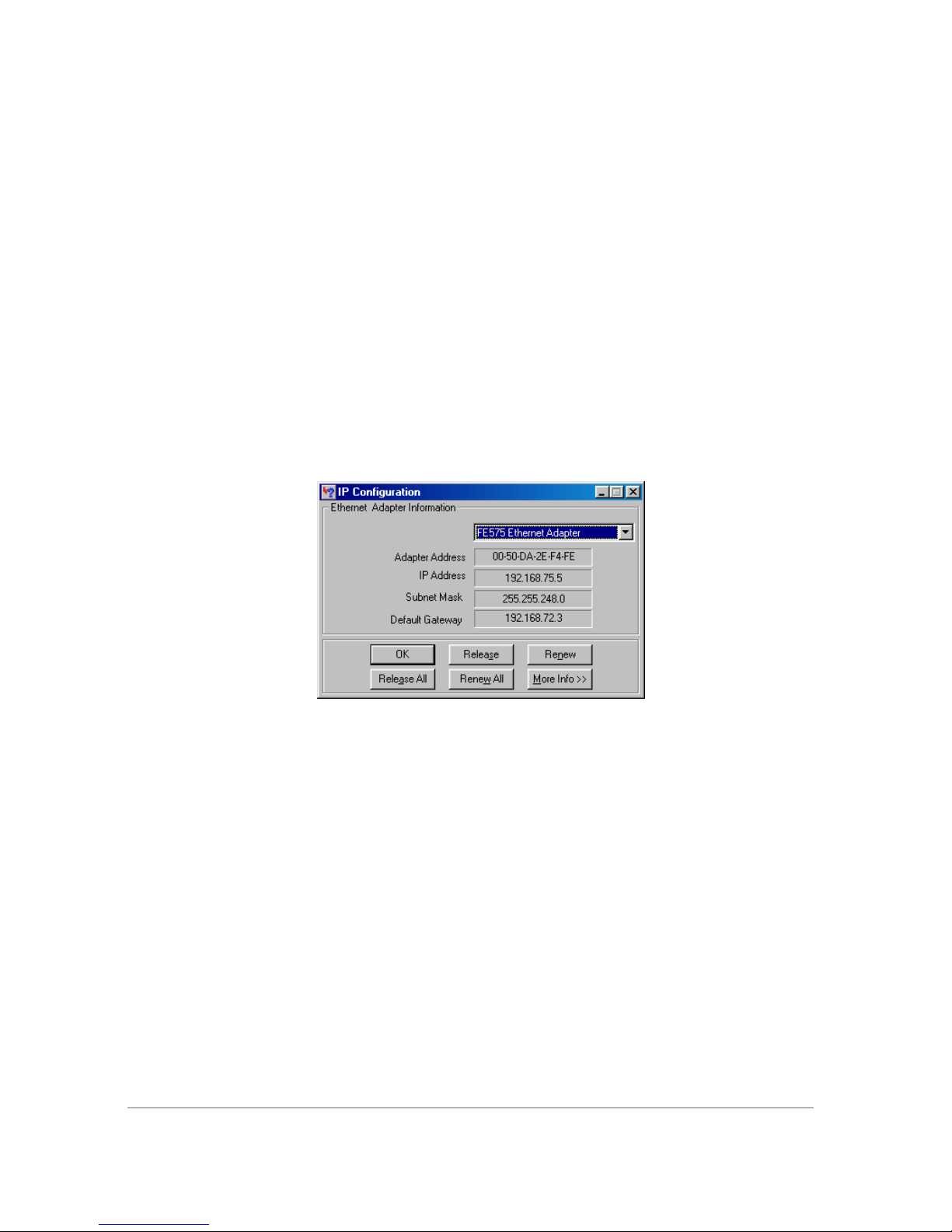
3. Type winipcfg.exe. A window similar to the example in Figure 17 appears.
Figure 17.
4. Select your adapter name.
5. Click Renew.
6. Click OK after the system displays the IP address.
If, after performing this procedure, your computer doesn't access the Internet, verify that
PWR, LAN, and CBL LEDs are steady green. Then call your Service Provider. They will
assist in verifying your configuration.
12 DOXport 1110 User’s Guide
Verifying IP Address
Page 23
Diagnostics
LED Identification
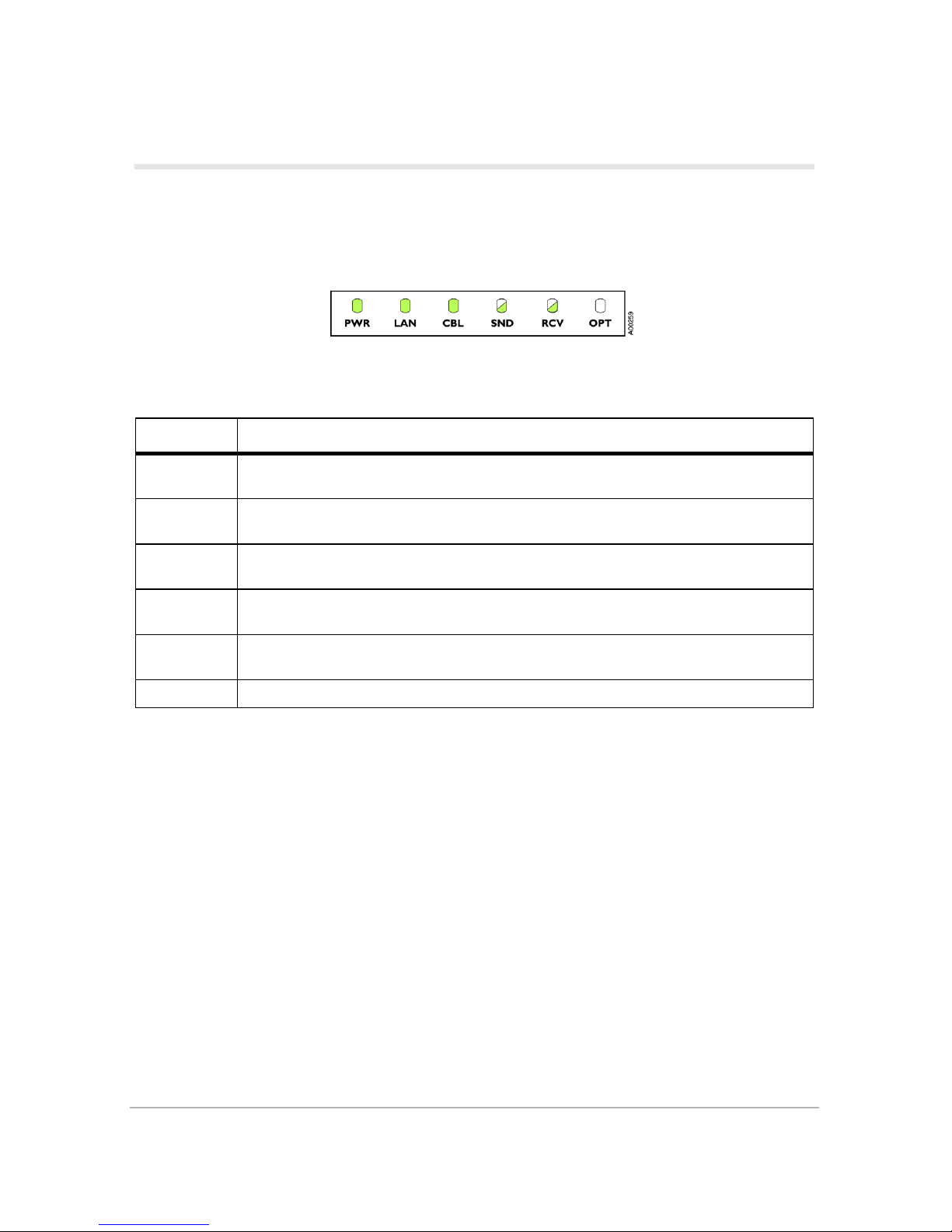
The DOXport 1110 modem has six front panel lights called LEDs (Light-Emitting Diodes).
The LEDs let you monitor status during installation and operation.
See Table 2 for a description of the six LEDs.
Table 2:
LED Description
PWR
LAN
CBL
SND
RCV
OPT This LED’s function is defined by your service provider.
Indicates whether power is being supplied to the modem. This LED is steady green
when the modem is powered.
Indicates the status of the modem’s connection to your computer. This LED is steady
green when a functional LAN connection (Ethernet or USB) is detected.
Indicates the modem’s acquisition state. This LED is steady green when the modem is
fully acquired.
Indicates that the modem is sending data. This LED flashes green when the modem is
sending data upstream.
Indicates that the modem is receiving data. This LED flashes green when the modem
is receiving downstream data.
DOXport 1110 LEDs
LED Acquisition States
When power is applied to the cable modem, the power LED turns solid green, indicating the
start or the acquisition process. The process will continue after the cable modem has
established a connection to the cable TV network. No additional intervention is required on
your part. The modem automatically acquires to and registers with the cable data network.
Diagnostics 13
Page 24
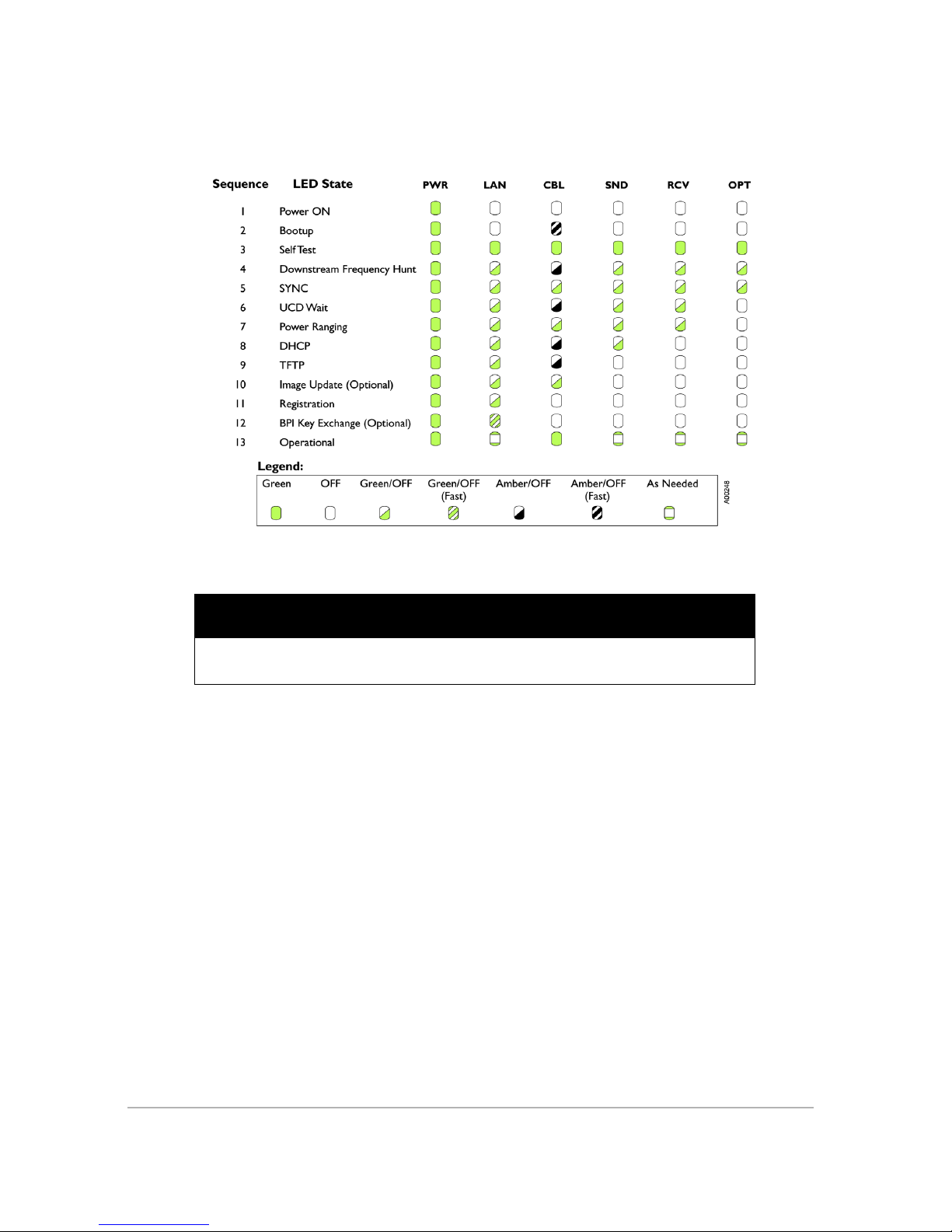
See Figure 18 for a graphical representation of the LED states during the acquisition process
(the LEDs will flash in synchrony).
Figure 18.
LED states
IMPORTANT
If the modem is set for “Network Access Denied” by your service operator, the modem
will remain in the Registration state (sequence 11). Contact your cable service provider.
14 DOXport 1110 User’s Guide
Page 25
Tro u bl e s h o o t i n g w i t h L E D s
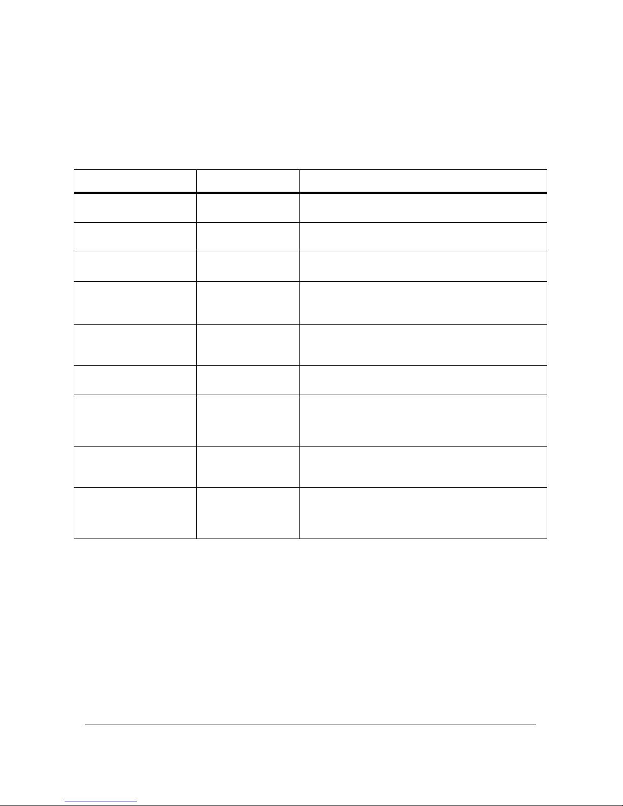
Table 3 provides possible solutions in the event that your LEDs indicate that the modem has
a problem.
Table 3:
Indication/LED State Problem Possible Solution
PWR LED off No power
None of the LEDs light upPower has not been
applied to LEDs
CBL LED steady amber Hardware failure
LAN LED off No Ethernet or USB
LEDs stuck in the Image
Update state
PWR LED is green and
CBL is flashing amber
LEDs stuck in the
Downstream Frequency
Hunt state.
Modem image update
Modem’s boot code
has failed to execute
Modem is searching
for downstream
frequency from the
Service Provider
LED Troubleshooting
Check power adapter connections, and power outlet. If
all appear to work, contact your Service Provider.
Check power adapter connections, and power outlet. If
all appear to work, contact your Service Provider.
Disconnect DC plug, wait 10 seconds and reconnect
DC plug. If no change, contact your Service Provider.
Check Ethernet/USB connection and computer power.
If using USB, check the USB driver (see “Checking the
USB Driver” on page 16).
Wait until update is complete (usually 2-10 minutes). If
the LEDs do not change, contact your Service
Provider.
Disconnect DC plug, wait 10 seconds and reconnect
DC plug. If no change, contact your Service Provider.
If the modem has been stuck in this state for longer
than 30 minutes, make sure the cable is firmly
connected at the modem and at the CATV outlet. If no
change contact your Service Provider.
LEDs stuck in the
Registration state
LEDs indicate normal
operation but modem
does not allow data
throughput
Modem is attempting
to register with the
Service Provider
Potential network
configuration issue
If the modem has been stuck in this state for longer
than 10 minutes, contact your Service Provider.
Check network configuration. If modem still does not
allow data throughput, contact your Service Provider.
Diagnostics 15
Page 26
Checking the USB Driver
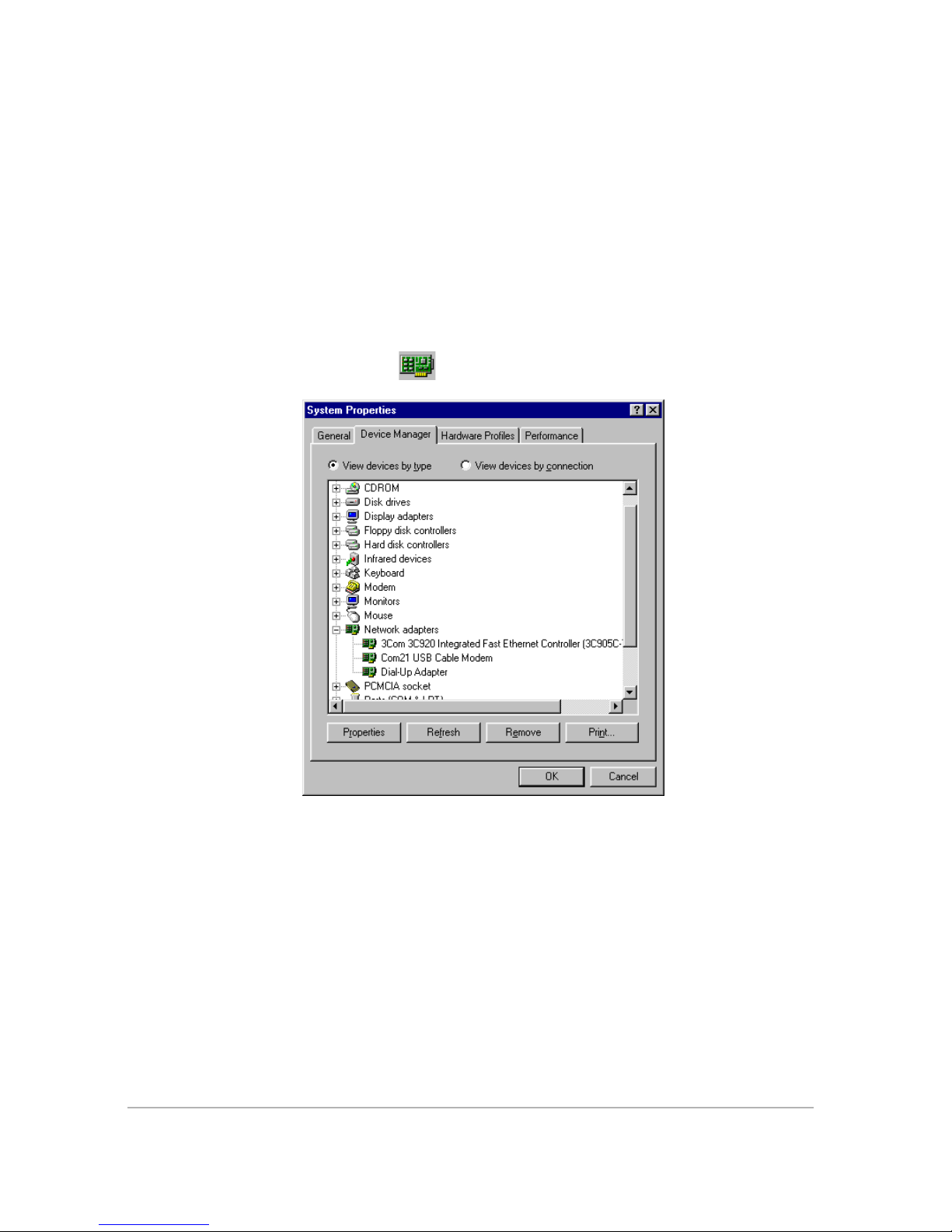
If you are connecting the cable modem to your Windows 98/Me/2000 computers
USB port, check if the USB driver is correctly installed.
— Click START -> SETTINGS -> CONTROL PANEL, then double
click the SYSTEM icon.
Select the DEVICE MANAGER tab and click the ‘+’ to expand the Network
Adapter devices. All working USB devices will appear on the System ‘Device
Manager’ window (Figure 19).
If the Com21 USB Cable Modem is properly installed, the Device Manager will
display it with this symbol
.
16 DOXport 1110 User’s Guide
Figure 19.
Device Manager
Page 27
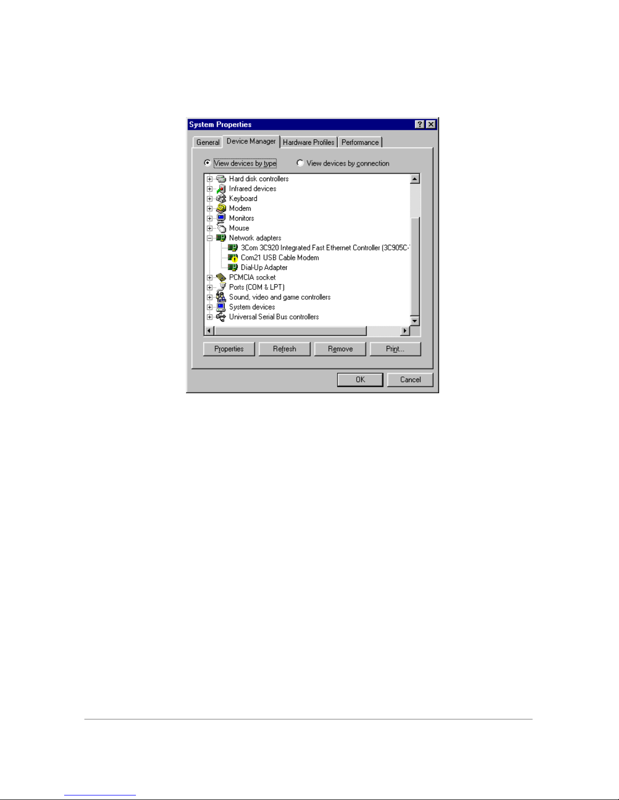
Otherwise, it will display a warning sign on top of the USB symbol (Figure 20). Make
sure the USB symbol represents the DOXport 1110 and not another USB device.
Figure 20.
USB Device with Warning Symbol
If the warning sign is displayed, there might have been an error during the
installation. Reboot the computer and check the device status again after reboot.
— Click START -> SHUT DOWN -> RESTART
— Click START -> SETTINGS -> CONTROL PANEL, then double
click the SYSTEM icon.
If the driver still has the warning after rebooting, remove it and reinstall it again.
— Click REMOVE and select ‘Remove from all configurations (Figure
21).
— Click OK and unplug the USB cable from the computer.
— Click REFRESH and make sure the warning USB symbol has been
removed.
Diagnostics 17
Page 28
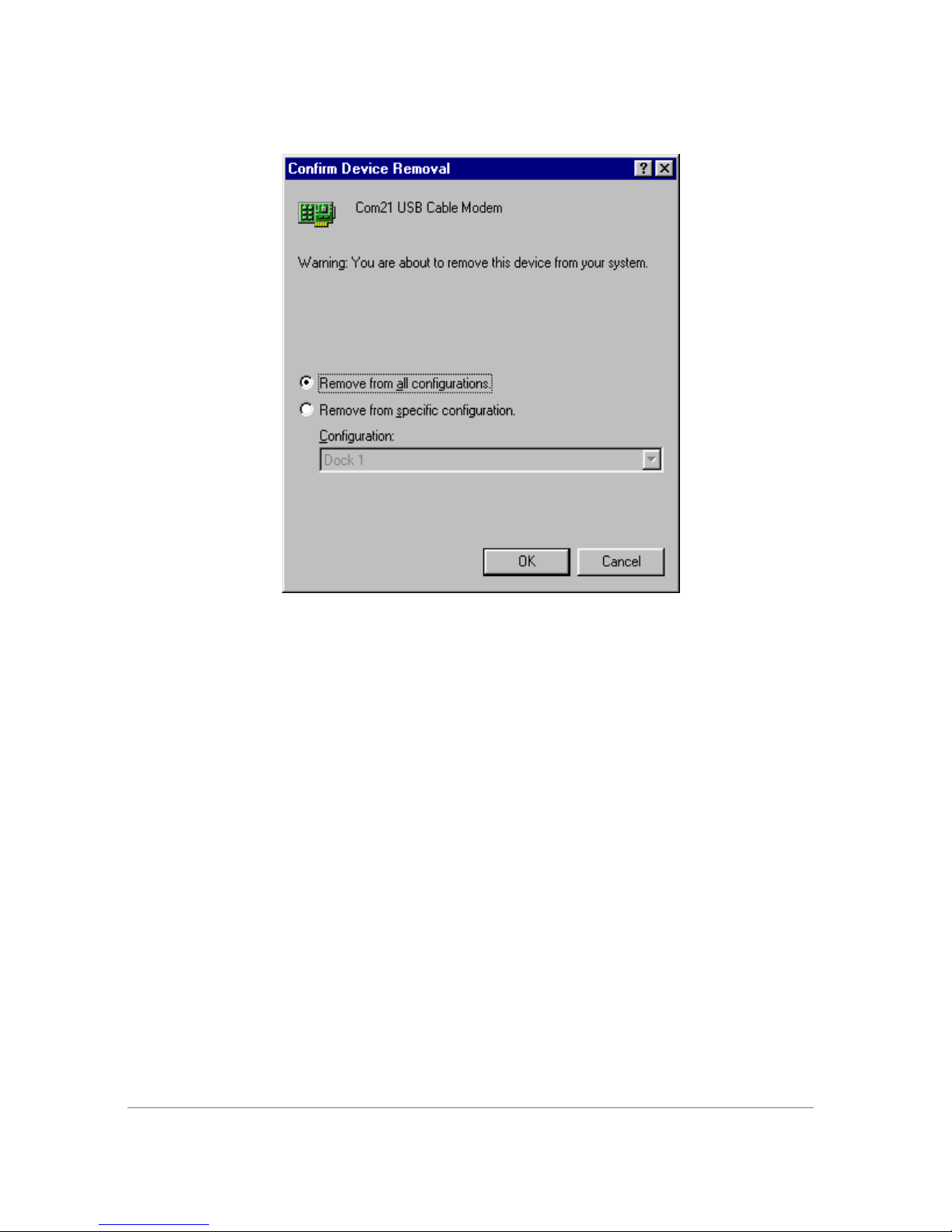
Reboot the computer and then follow the installation procedure again.
Figure 21.
Removing USB Driver
18 DOXport 1110 User’s Guide
Page 29
DOXport 1110 Specifications
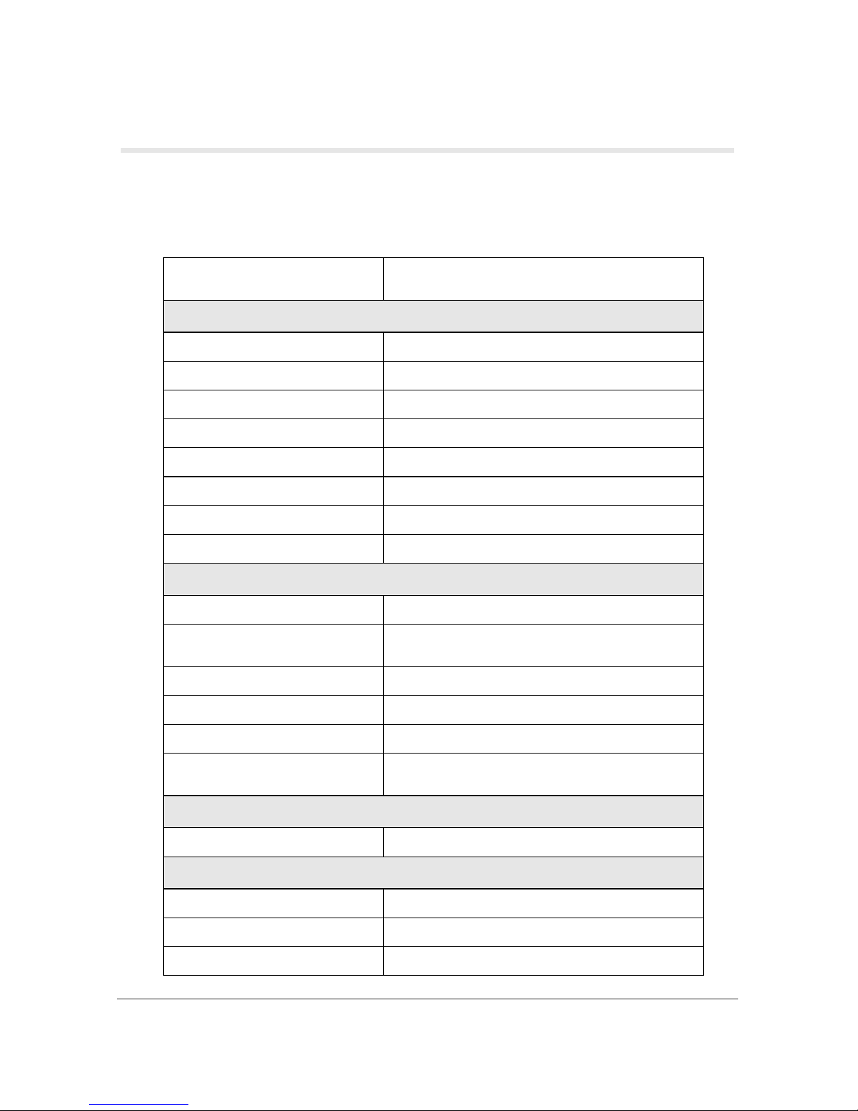
The Com21 DOXport 1110 cable modem complies with DOCSIS specifications. Table 4 lists
detailed operating and environmental specifications.
Table 4:
Specifications
Parameter Specification
DOWNSTREAM
Demodulation 64QAM/256QAM
Physical speed 30 Mbps (64QAM) / 43 Mbps (256QAM)
Error correction Reed Solomon + Trellis (Enhances Annex B)
Frequency range 88 MHz to 860 MHz (edge-to-edge)
Bandwidth 6 MHz
Input signal level -15dBmV to +15dBmV
Input impedance 75 ohms
Return loss > 6 dB from 88 MHz to 860 MHz
UPSTREAM
Modulation QPSK /16QAM
Physical speed
320, 640, 1280, 2560, 5120 Kbps (QPSK)
640, 1280, 2560, 5120, 10240 Kbps (16QAM)
Error correction Reed Solomon
Frequency range 5 to 42 MHz (edge-to-edge)
Bandwidth 200, 400, 800, 1600, 3200 kHz
Output signal level
+8 dBmV to +58 dBmV (QPSK)
+8 dBmV to +55 dBmV (16QAM)
SNMP MANAGEMENT
MIB Group MIB II, MCNS MIB
INTERFACES
Ethernet 10/100 Base-T (full duplex), RJ-45 Connector
Cable F type female connector, 75 ohm
USB USB 1.1, B-Type female connector
DOXport 1110 Specifications 19
Page 30
Ta b l e 4 :
Specifications (continued)
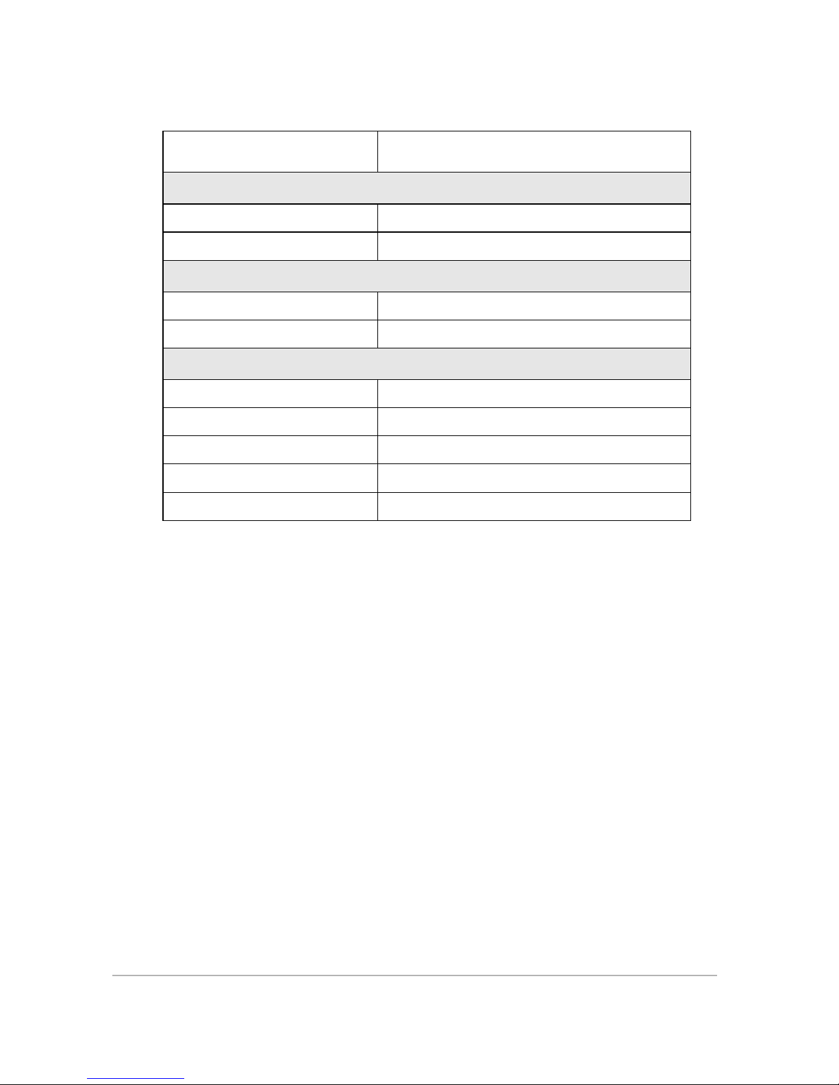
Parameter Specification
POWER
Power input 15 VDC @1A
Power consumption 7 W (Max)
MECHANICAL
Size 1 in. (H) x 6.625 in.(W) x 5.75 in. (D)
Weight 13.9 oz
ENVIRONMENTAL
Operating temperature 0°C to +40°C
Humidity 10 % to 90 % (non-condensing)
Storage temperature -40°C to +75°C
Safety UL/cUL, TUV, CE
Emission FCC part 15, class B
20 DOXport 1110 User’s Guide
Page 31

Warranty
Subject to the provisions described below, Com21 warrants to the original purchaser that the DOXport
1110 ("Product") will materially conform to the specifications applicable to such product and will be free
from defects in materials and workmanship under normal and proper use for a period of five (5) years
from the date of purchase. This warranty shall not apply to any damage or defect arising as a result of
neglect, improper installation, alteration, accident, or improper use of the Product. This limited warranty
gives you specific legal rights and you may have other rights which vary from state to state.
No other express warranties are made or authorized with respect to the Product. The warranties with respect to the Product, including without limitation, warranties of merchant ability,
fitness for a particular purpose and non infringement, are limited in duration to the warranty
period.
Some states do not allow limitations on how long an implied warranty lasts, so the above limitations may not apply to you. Com21's sole liability under this warranty is, at the option of
Com21, during the warranty period, and upon proof of purchase, to repair or replace Products that do not conform with the foregoing warranty.
THIS WARRANTY IS SPECIFICALLY IN LIEU OF, AND COM21 DISCLAIMS, ALL
OTHER WARRANTIES, EXPRESS OR IMPLIED, INCLUDING, WITHOUT LIMITATION, ANY WARRANTY FOR MERCHANTABILITY, FITNESS FOR A PARTICULAR
PURPOSE AND NON-INFRINGEMENT. FURTHER, COM21 DOES NOT WARRANT, GUARANTEE OR MAKE ANY REPRESENTATION REGARDING THE USE,
OR THE RESULTS OF THE USE, OF THE COM21 PRODUCTS OR RELATED DOCUMENTATION IN TERMS OF CORRECTNESS, ACCURACY, RELIABILITY OR
OTHERWISE. IN NO EVENT WILL COM21 BE LIABLE FOR ANY LOST PROFITS,
COST OF PROCUREMENT OF SUBSTITUTE PRODUCTS OR ANY INCIDENTAL
OR CONSEQUENTIAL DAMAGES ARISING OUT OF THE USE OR INABILITY TO
USE SUCH PRODUCT EVEN IF COM21 HAS BEEN ADVISED OF THE POSSIBILITY OF SUCH DAMAGES. SOME STATES DO NOT ALLOW THE EXCLUSION OR
LIMITATION OF INCIDENTAL OR CONSEQUENTIAL DAMAGES, SO THE
ABOVE LIMITATION AND EXCLUSIONS MAY NOT APPLY TO YOU.
Unless the law of your state otherwise requires, any claim under this Limited Warranty must
be submitted to your place of purchase before the end of the warranty period. At time of purchase, you should record the place and date that you purchased the Product. Warranty service
and related procedures can be obtained from the place of purchase where you purchased the
Product. To obtain warranty service, you must also provide proof of original date of purchase.
Com21, Inc.
750 Tasman Drive
Milpitas, CA 95035 USA
DOXport 1110 Specifications 21
Page 32

22 DOXport 1110 User’s Guide
Page 33

Index
Numerics
16QAM, 19
64QAM/256QAM, 19
B
bandwidth, 19
C
CATV, 1
configuration, 12
D
data channel, 13
demodulation, 19
DOCSIS, 1, 19
E
emission, 20
environment, 19
error correction, 19
Ethernet, 10, 11
M
MCNS, 19
MIB, 19
O
obtain IP address, 12
operating system, 9, 12
output signal level, 19
P
physical speed, 19
power consumption, 20
protocol option, 10
Q
QPSK, 19
R
Reed Solomon, 19
return loss, 19
Reliance Fundamentals
F
FCC, 20
frequency range, 19
I
input impedance, 19
input signal level, 19
interference, iii
Internet, 12
IP address, 9, 11, 12
Index Index-1
S
select adapter, 12
service provider, 12
SNMP, 19
status, 13
T
TCP/IP, 9, 10
Trellis, 19
Page 34

U
UL1310, 20
UL1950, 20
V
ventilation, 2
W
Windows, 9
winipcfg.exe, 12
Index-2 DOXport 1110 User’s Guide
 Loading...