

Page 1

INSTALLATION, OPERATION
& SERVICE MANUAL
MONITOR
Pulse™ Monitor Software Version 1.0.1
Pulse™ Monitor Card Software Revision 1.4.0
Pulse™ Monitor Card Product Revision 0.1.0.0
MONITOR
P/N: 11817503 REV. AA June 2014
Page 2

TABLE OF CONTENTS
Introduction �������������������������������������������������������������������������������������� 3
INSTALLATION
Pulse Monitor Kits ������������������������������������������������������������������������ 4–5
Software Installation ������������������������������������������������������������������������� 6
Initial Programming �������������������������������������������������������������������������� 6
Tools Required For Installation ��������������������������������������������������������� 7
Mounting Pulse Monitor Card ���������������������������������������������������������� 7
Wiring ����������������������������������������������������������������������������������������������� 8
OPERATION
Specifications ����������������������������������������������������������������������������������� 9
Downloading Motor Data ���������������������������������������������������������� 10–11
Software Functions ������������������������������������������������������������������������ 11
Cumulative Data ����������������������������������������������������������������������������� 11
Monitor Version ������������������������������������������������������������������������������ 12
Assigning Serial Number ���������������������������������������������������������������� 12
Setting Time and Date �������������������������������������������������������������������� 12
Setting Voltage ������������������������������������������������������������������������������� 13
Reading Data ���������������������������������������������������������������������������������� 13
Voltage Graph ��������������������������������������������������������������������������������� 13
Data Filters ������������������������������������������������������������������������������������� 14
Viewing Data Type (Current vs� History) ����������������������������������������� 14
Changing Order of Data Grid ��������������������������������������������������������� 15
Saving and Printing Motor Data ����������������������������������������������������� 15
SERVICE
Troubleshooting Chart �������������������������������������������������������������������� 16
Appendix 1 – Wiring Diagrams ������������������������������������������������� 17–23
Appendix 2 – Voltage Measurement Accuracy ������������������������������ 24
Replacement Parts ��������������������������������������������������������������������������� 24
Customer Service ���������������������������������������������������������������������������� 24
MONITOR
NOTE: Pulse is not a trademark of Columbus McKinnon Corporation.
2
P/N: 11817503 REV. AA June 2014
Page 3

INTRODUCTION
Congratulations on the purchase of a Pulse monitor� The Pulse monitor is an electronic device that records
key information with a time/date stamp every time an AC motor is turned on� The program data can be used
as a tool to help assist you in trouble shooting hard to figure out field problems for machinery-using AC motors
and help determine preventative maintenance intervals�
IMPORTANT! PLEASE READ!
Before proceeding any further, please read the following important information regarding the Pulse monitor
and its proper handling and use:
The pulse monitor is powered by AC control voltage, which can cause electric shock resulting in personal injury or
loss of life. Handle monitor card with the same care and caution as all other high voltage electrical components.
Be certain the electrical power supply is OFF and locked in the open position before attempting any electrical
connections to the hoist.
Be sure to disconnect all AC input power before downloading information from or handling the Pulse monitor
circuit board.
Please read this manual completely before installing the Pulse monitor.
The Pulse monitor card must be rigidly secured in the control panel as illustrated in this manual.
Failure to do so may result in damage to the pulse monitor card and to the equipment being monitored
Only qualified personnel should perform service.
MONITOR
3
P/N: 11817503 REV. AA June 2014
Page 4
PULSE MONITOR KITS
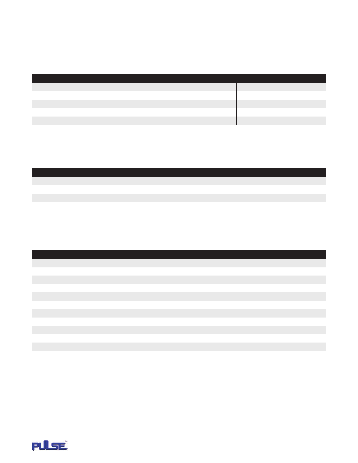
The Pulse monitor is available in several different kit varieties to accommodate individual needs�
Note: Shaw-Box World Series and Yale Global King hoists, which include the Pulse monitor card as standard, require a computer
interface kit (sold separately) to read the data� Kit variations are as follows:
PULSE MONITOR COMPUTER INTERFACE KIT WITH USB ADAPTOR
CATALOG NO� PINTERFACEUSB
Description Quantity
Pulse Monitor Computer Interface (9V battery not included) 1
Serial Extension Cable (6 ft.) 1
Pulse Monitor Software Disk 1
StarTech.com USB Adaptor Software Disk 1
Serial Port to USB Adaptor Cable (3 ft.) 1
Note: Kit also includes a DB9 to DB25 pin adapter for 25-pin RS232 serial communication which will not be needed in most cases�
PULSE MONITOR COMPUTER INTERFACE KIT WITHOUT USB ADAPTOR
CATALOG NO� PINTERFACEKIT
Description Quantity
Pulse Monitor Computer Interface (9V battery not included) 1
Serial Extension Cable (6 ft.) 2
Pulse Monitor Software Disk 1
PULSE MONITOR COMPLETE KIT
CATALOG NUMBERS
PCOMPLETEKIT1 = 115 VAC CONTROL
PCOMPLETEKIT2 = 24 VAC CONTROL
Description Quantity
Pulse Monitor Card 1
Card Mounting Bracket 1
Pulse Monitor Computer Interface (9V battery not included) 1
Serial Extension Cable (6 ft.) 2
Pulse Monitor Software Disk 1
StarTech.com USB Adaptor Software Disk 1
Serial Port to USB Adaptor Cable (3 ft.) 1
Pan Head Phillips Screw Self Tap #6-32 X 5/8" 6 (2 extra)
Pan Head Phillips Screw Self Tap #10-24 X 1/4" 3 (1 extra)
Terminal Wire Insulated Female Quick Connector Panduit Part no. DNR14-188F1B-C (tab size 0.187 X 0.020) 10 (3 extra)
16# Insulated Wire 15 ft.
Note: Kit also includes a DB9 to DB25 pin adapter for 25-pin RS232 serial communication which will not be needed in most cases�
MONITOR
4
P/N: 11817503 REV. AA June 2014
Page 5
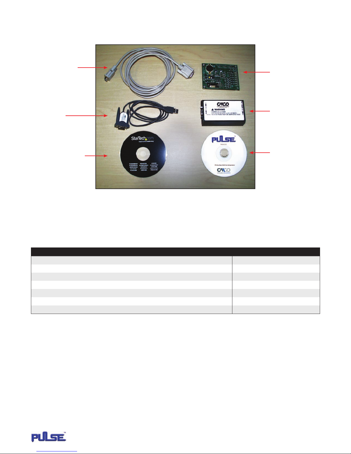
PULSE MONITOR KITS (CONTINUED)
PULSE MONITOR COMPLETE KIT
SERIAL EXTENSION CABLE
SERIAL PORT TO USB
ADAPTOR CABLE
USB ADAPTOR SOFTWARE DISK
Note: Kit also includes a DB9 to DB25 pin adapter for 25-pin RS232 serial communication which will not be needed in most cases�
PULSE MONITOR CARD
COMPUTER INTERFACE
PULSE MONITOR
SOFTWARE DISK
PULSE MONITOR INDIVIDUAL CARD KIT
CATALOG NUMBERS
PCARDKIT1 = 115 VAC CONTROL
PCARDKIT2 = 24 VAC CONTROL
Description Quantity
Pulse Monitor Card 1
Card Mounting Bracket 1
Pulse Monitor Software Disk 1
Pan Head Phillips Screw Self Tap #6-32 X 5/8" 6 (2 extra)
Pan Head Phillips Screw Self Tap #10-24 X 1/4" 3 (1 extra)
Terminal Wire Insulated Female Quick Connector Panduit Part no. DNR14-188F1B-C (tab size 0.187 X 0.020) 10 (3 extra)
16# Insulated Wire 15 ft.
MONITOR
5
P/N: 11817503 REV. AA June 2014
Page 6

SOFTWARE INSTALLATION
Insert the Pulse software disk into your CDROM drive� Using the
RUN command in your start menu button, browse to your CDROM
drive� Open folder 1�0�1� Double click on the Install Pulse file�
Select OK and follow instructions� During the install, say yes to
installing the Microsoft�net framework program if prompted�
This is necessary for the Pulse software to operate�
OBSERVE MINIMUM SYSTEM REQUIREMENTS:
Operating System* – Windows XP Pro SP2, or Windows 2000 SP4.
CPU – Pentium III, 450 MHz, RAM - 256 MB.
Hard Drive Space – 50MB.
One USB Serial Port, CDROM Drive.
*Please Note: Windows 8 & 8�1 not supported�
INITIAL PROGRAMMING
Initial programming can be done before or after the Pulse
monitor card is installed� Open the Pulse software on your
computer and connect the Pulse monitor card as shown in
Figure 3� It is recommended that the following parameters
be set before collecting any data�
SERIAL NUMBER
In the Serial Number Box, enter the serial number for
the system you wish to monitor� Click on the Set button
to program the serial number�
MONITOR DATE
In the Monitor Date Box, click on the Set button to set the monitor
card clock to your computers clock�
Note: If this is not done, the default time for the monitor card
is midnight, January 1, 1970�
USB ADAPTER INSTALLATION
DRIVER
1� Turn on computer on and boot into Windows� Do not have
USB adapter plugged into the computer
2� Insert the driver CD into your CD/DVD drive� If AutoPlay runs,
then choose to “Browse the CD”, otherwise access the contents
of the CD via “my Computer”
3� In the “Prolific/PL2302X” location, open the appropriate folder
for your operation system and run the setup�exe file� This will
launch the driver installation wizard
4� Once the installation wizard completes, the drivers will be
installed and ready for use�
HARDWARE INSTALLATION
1� Make sure the driver installation has been completed first�
2� Plug the USB adapter into an available USB port on the
computer system�
3� Windows will automatically detect the USB adapter and
install the drivers
4� Once installation is complete, the serial port will be ready for use�
5� If connecting the serial port to a DB25 interface, use the included
DB9 to DB25 (male) adapter
VOLTAGE
In the Voltage Box, enter the source voltage the motor is being
powered by� Click on the Set button to program the source voltage�
For further information concerning these parameters,
see the Software Functions section of this manual.
VERIFYING INSTALLATION
Windows XP/Vista/7
1� From the main desktop, right click on “my computer”
(“Computer” in Vista/7) then select Manage� In the new
Computer Management window, select Device Manager
from the left window panel�
2� Double click on the “Ports (COM & LPT)” option�
The additional ports should be visible�
3� Double click on the adapter
4� Select “Port Settings” tab
5� Click on “Advanced” and at the bottom of the pop-up screen
under “COM Port Number” make sure COM1, COM2, COM3
or COM4 is selected� The Pulse software will only detect COMs
1 thru 4�
MONITOR
6
P/N: 11817503 REV. AA June 2014
Page 7
TOOLS REQUIRED FOR INSTALLATION
• Drill & #19 Drill Bit (ø .166")
• #1 Phillips Screw Driver
• Wire Strippers
• Connector Crimping Tool (Sized for 16# wire)
MOUNTING PULSE MONITOR CARD
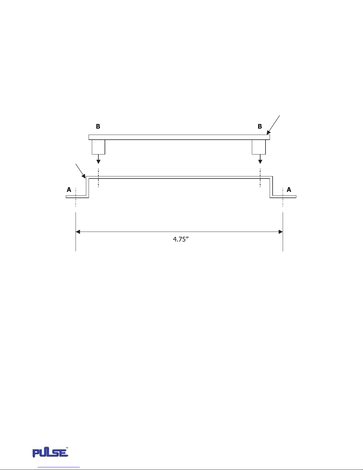
1� Locate available space in control enclosure to t the required 3" X 5-1/4" X 2-1/2" envelope. Use a #19 drill bit (ø .166") and drill two
holes 4.75" +/- .02" apart. Attach the mounting bracket using (2) #10-24 X ¼" self-tapping screws at reference points A� See Figure 1�
2� Attach Pulse monitor card to mounting bracket using (4) #6-32 X 5/8" self-tapping screws at reference points B� See Figure 1�
PULSE MONITOR CARD
MOUNTING BRACKET
FIGURE 1
MONITOR
7
P/N: 11817503 REV. AA June 2014
Page 8
WIRING
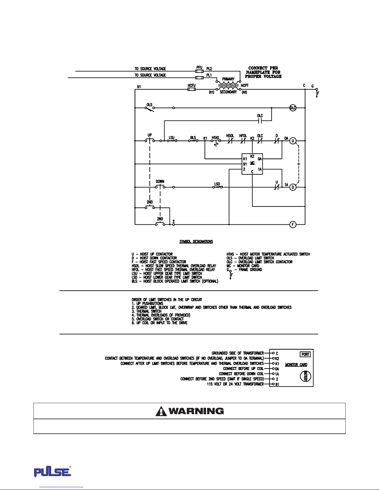
1� 1) Review electrical schematic� See Figure 2�
2� 2) See Appendix 1 for detailed wiring diagrams specific to selected Yale·Lift-Tech arrangements�
FIGURE 2
The Pulse monitor card is electronic equipment that requires earth ground to reduce potential for false data�
If a dedicated ground is not available, make sure reference ground to all control transformers have one common point�
MONITOR
8
P/N: 11817503 REV. AA June 2014
Page 9
SPECIFICATIONS
The Pulse monitor records the following information:
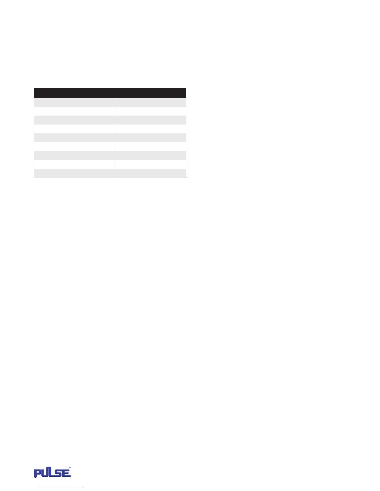
MOTOR EVENT PARAMETERS
Motor direction is referenced as Up or Down� The Pulse monitor
can record up to two speed points� The speed points are referenced
as Slow and Fast�
The following are all the designated motor events that can be
recorded:
Motor Event Data Filters
Motor Up Slow
Motor Up Fast
Motor Down Slow
Motor Down Fast
Plug Event Excessive Plugging
Motor Trip Up Thermal Shutdown
Motor Trip Up Fast Thermal Shutdown
Over Capacity Up
Over Capacity Up Fast
CURRENT MOTOR EVENTS
The Pulse monitor records all current motor events up to a maximum
of 5119 events� After 5119, each new motor event will record over
the oldest motor data beginning at memory count one�
HISTORY EVENTS
The Pulse monitor records the following motor events simultaneously
into the current and history motor event memory registers�
The motor events are plug event, motor trip and over capacity�
The history event register can store up to 64 occurrences before
recording over the oldest data located in memory count one�
(Normal Start), (Slow), (Up)
(Normal Start), (Fast), (Up)
(Normal Start), (Slow), (Down)
(Normal Start), (Fast), (Down)
(Plug Event)
(Motor Trip), (Up)
(Motor Trip), (Up)
(Over Capacity), (Up)
(Over Capacity), (Up)
PLUG EVENT (EXCESSIVE PLUGGING)
A plug event is recorded when the directional contactor (node 0A
or 1A) is energized four times within any two second period of
operation� The plug event is recorded simultaneously into current
motor data and history data�
MOTOR TRIP EVENT
A motor trip event will be recorded when the monitor card terminal
K1 measures 115 volts* and terminal K2 is at 0 volts� If the event
occurs with all three terminals K1, K2 and 0A being at 0 volts
followed by numerous occurrences of terminal K1 sensing 115 volts*
and K2 remaining at 0 volts, only one event will be recorded�
OVER CAPACITY EVENT
An overcapacity trip will be recorded when the monitor card
terminals K1 and K2 measure 115 volts* and terminal 0A being at
0 volts� If the event occurs with all three terminals K1, K2 and 0A
being at 0 volts followed by numerous occurrences of terminal K1
and K2 sensing 115 volts* and 0A remaining at 0 Volts, only one
event will be recorded�
VOLTAGE
For every motor event, the voltage will be measured�**
TIME / DATE STAMP
All motor events are recorded along with the time and date the motor
event occurred� The real time clock in the Pulse monitor card has a
default starting time of midnight, January 1, 1970� Once the Pulse
monitor software connects to the card, you can change the default
time to your computer's time by pressing the Set button�
* All cited voltages are nominal referenced to ground using the
115-volt monitor card� If using the 24-volt card, all non-zero
voltage references will be 24 volts�
** See Appendix 2 for discussion of accuracy�
CUMULATIVE RUN TIME
Every time the motor is energized, the Pulse monitor records how
long it runs and adds to the cumulative total run time� Maximum
time count is 1�9 million hours� Cumulative run time is updated
every 16 motor starts� Overall operating time cannot be reset
to zero� Cumulative Motor Starts - Pulse monitor keeps track
of overall starts of a motor� Maximum start count is 4�29 billion�
The cumulative memory location is updated every 16 motor
starts� Overall starts cannot be reset to zero�
MOTOR STARTS
A motor start is recognized by energization of either the slow or fast
motor winding for 300ms or more�
* Pulse monitor card revision 1�4�0 - counts a motor start
when either the slow or fast winding of the motor is energized�
No time constraints are in place for determining a motor start�
MONITOR
9
P/N: 11817503 REV. AA June 2014
Page 10
DOWNLOADING MOTOR DATA
Motor event data stored in the Pulse monitor card can only be read using a personal computer (PC).
CONNECTIONS
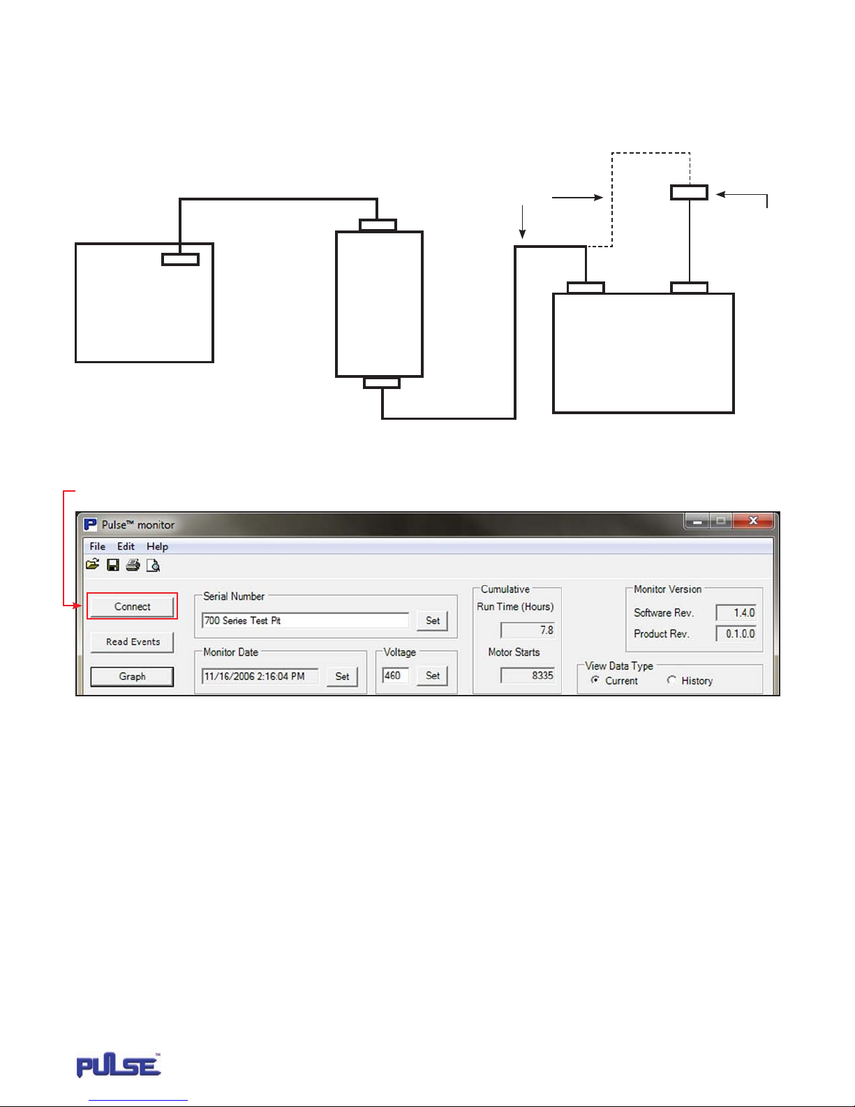
1� Connect the Pulse monitor card, computer interface, PC and serial extension cables as shown in Figure 3�
Serial Extension Cable
Connect to
Monitor Card
*Serial Port to USB
Adaptor Cable
PULSE
MONITOR
CARD
FIGURE 3
*Note: For optional use of USB port or devices without a serial port.
2� Select com port
3� Open Pulse monitor software on computer and press the Connect button� See Figure 4�
COMPUTER
INTERFACE
Connect to
Computer
Serial Port
USB Port
PC
FIGURE 4
MONITOR
10
P/N: 11817503 REV. AA June 2014
Page 11
DOWNLOADING MOTOR DATA (CONTINUED)
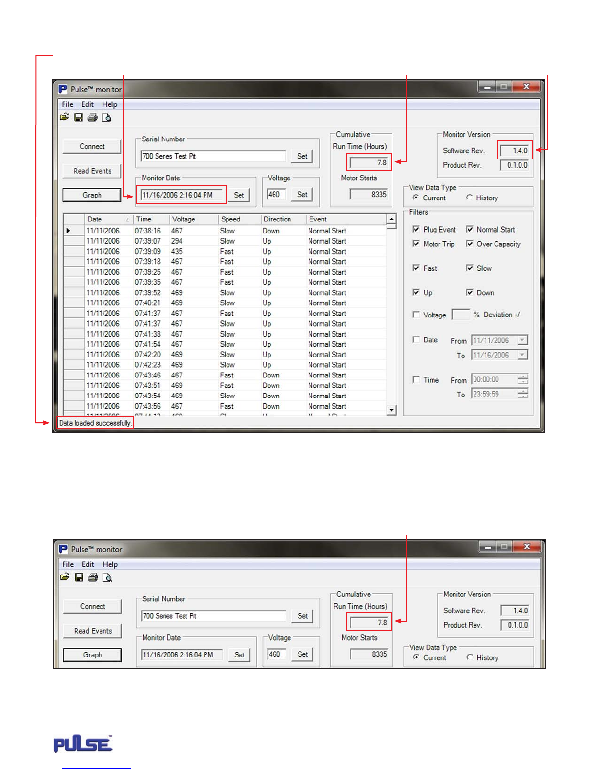
4� If your connection was successful, the following message Data loaded successfully will be displayed in the lower left corner�
The monitor date, monitor version and cumulative run time / start data will also appear� See Figure 5�
FIGURE 5
SOFTWARE FUNCTIONS
CUMULATIVE DATA
The Pulse monitor card keeps track of total motor run time and total motor starts for the motor being monitored�
The displayed cumulative data is automatically updated every 16 motor starts� Note this data cannot be reset� See Figure 6�
FIGURE 6
MONITOR
11
P/N: 11817503 REV. AA June 2014
Page 12
SOFTWARE FUNCTIONS (CONTINUED)
MONITOR VERSION
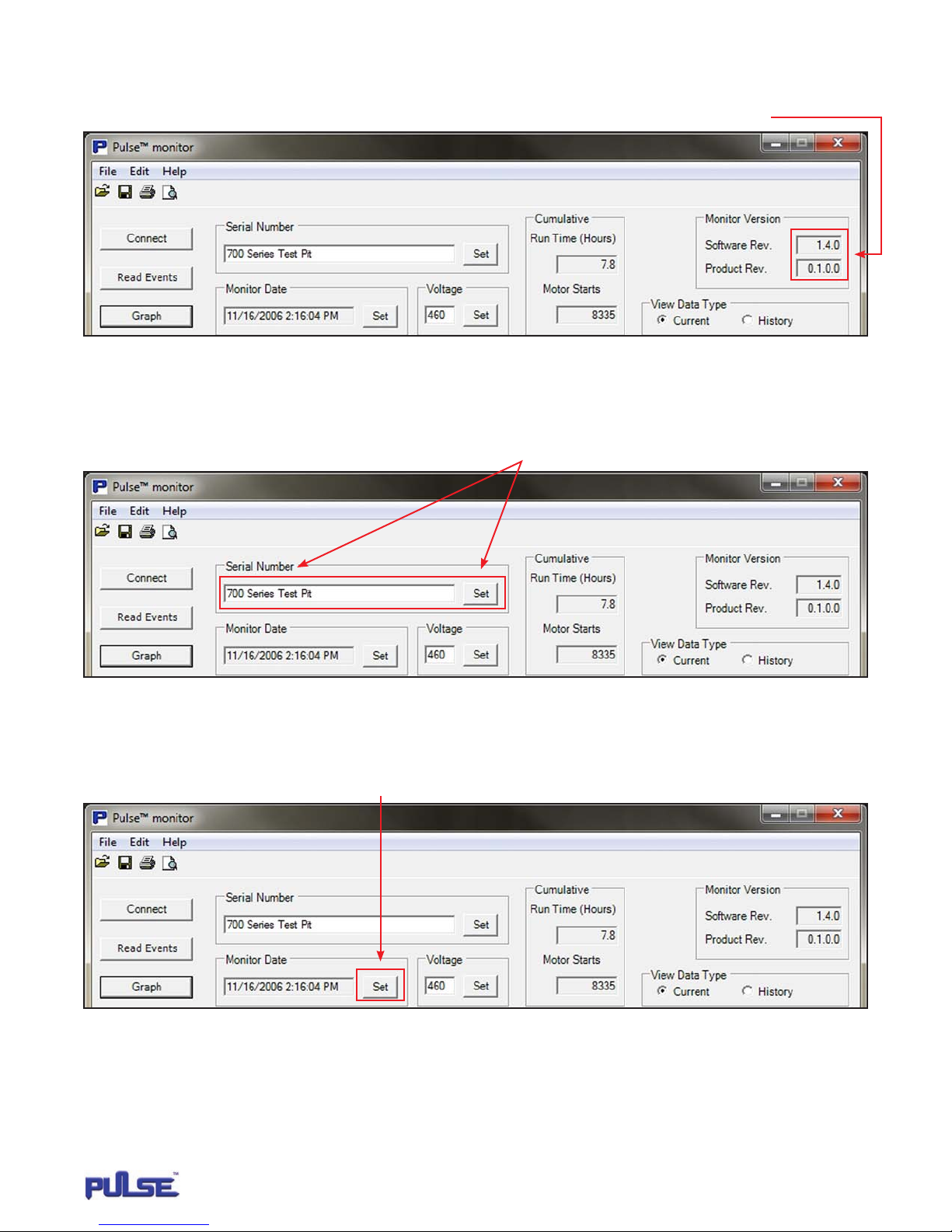
The Pulse monitor software and card revision number will automatically display once you connect to the card� See Figure 7�
FIGURE 7
ASSIGNING SERIAL NUMBER
You can assign a specific serial number to the Pulse monitor card up to 20 characters for the system you wish to retrieve data from� Click on
the serial number box and enter the respective serial number� Then press the Set button� See Figure 8�
FIGURE 8
SETTING TIME AND DATE
The time / date of all Pulse monitor cards default to midnight, January 1, 1970� By pressing the Set button in the Monitor Date box,
the software will automatically update the time in the Pulse monitor card to match the computer being used� See Figure 9�
FIGURE 9
MONITOR
12
P/N: 11817503 REV. AA June 2014
Page 13
SOFTWARE FUNCTIONS (CONTINUED)
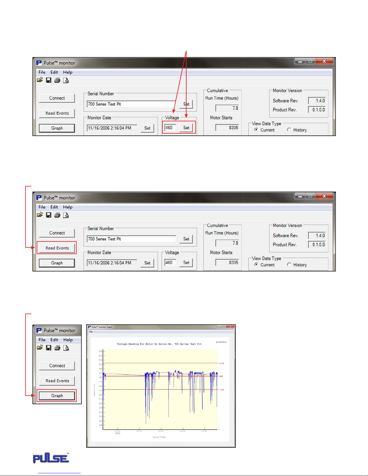
SETTING MOTOR VOLTAGE
The Pulse monitor card monitors the motor voltage of your system�* Enter the correct power supply voltage required for your system,
and press the Set button in the Voltage box� See Figure 10�
FIGURE 10
* See Appendix 2 for discussion of accuracy�
READING DATA
Pressing the Read Events button as shown in Figure 11 will read all data accumulated in the Pulse monitor card�
FIGURE 11
VOLTAGE GRAPH
Press the Graph button to read a graph showing a broad snapshot of what the voltage was for all motor events�*
See Figure 12� Note: To view graph at a specific date or time, select pertinent date/ time in filter box�
FIGURE 12
MONITOR
13
P/N: 11817503 REV. AA June 2014
Page 14
SOFTWARE FUNCTIONS (CONTINUED)
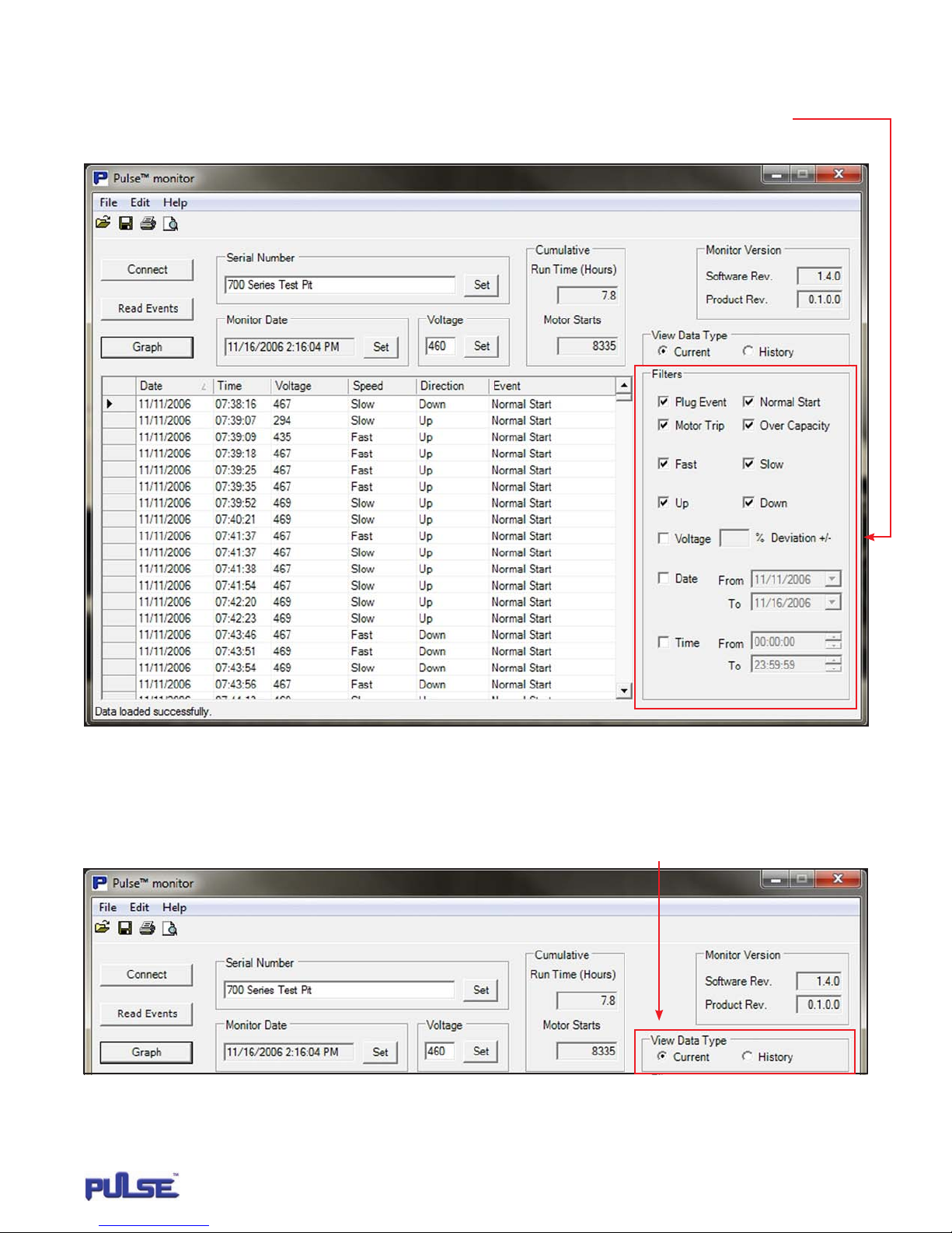
DATA FILTERS
Data filters allow you to narrow down the specific type of data you wish to view� The default selects all motor events for review�
If there is specific data you do not wish to see, simply uncheck the respective box and that data will be removed from your data grid�
The filters include the different motor event types, voltage deviation, specific date and specific time� See Figure 13�
FIGURE 13
VIEW DATA TYPE (CURRENT VS. HISTORY)
The View Data Type box allows you to choose between Current data, which is the most recent motor events up to a maximum of 5119,
or History data� History data is reserved specifically for Plug Event, Motor Trip and Over Capacity events� The maximum memory count
is 64 for each event type� See Figure 14�
FIGURE 14
MONITOR
14
P/N: 11817503 REV. AA June 2014
Page 15
SOFTWARE FUNCTIONS (CONTINUED)
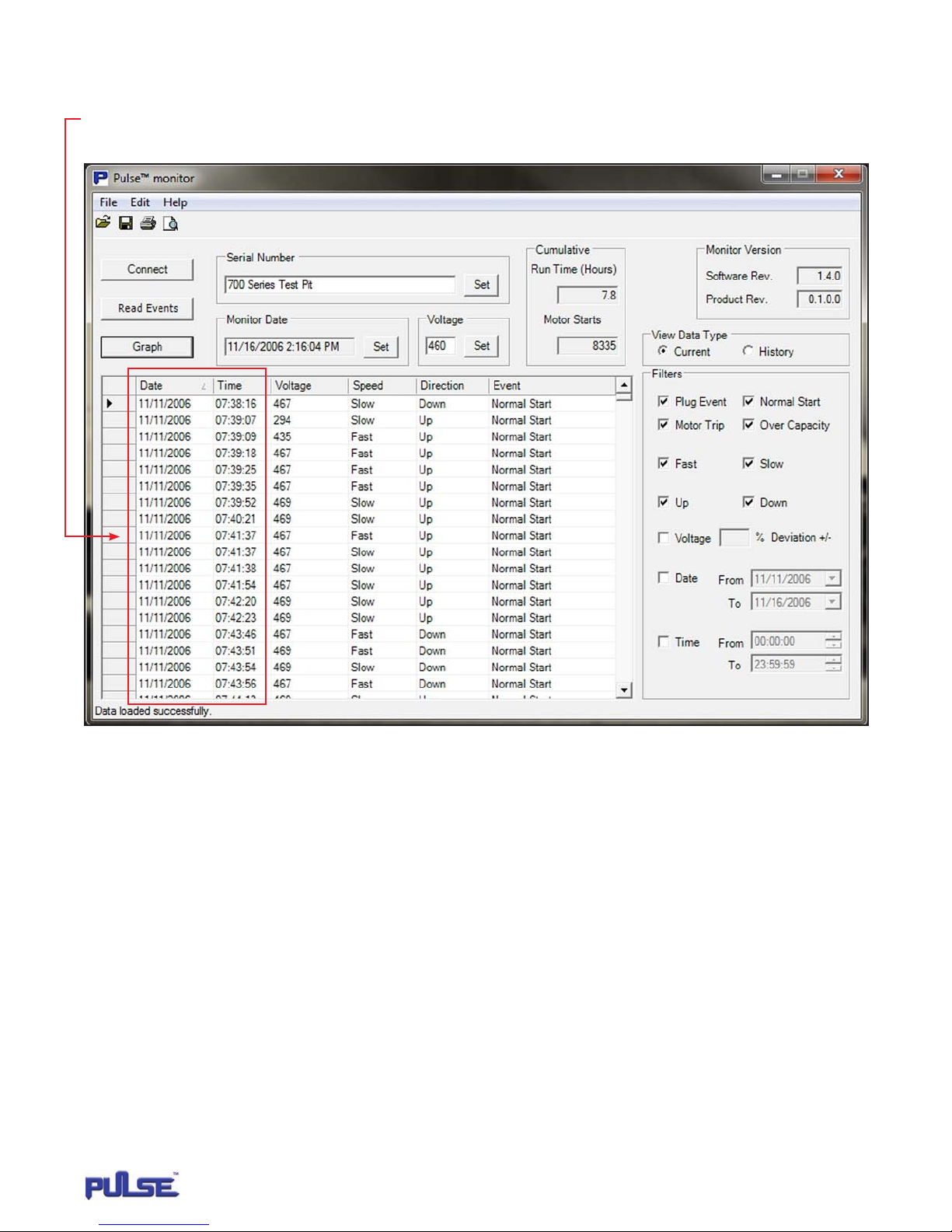
CHANGING ORDER OF DATA GRID
You can also change the order in which you view the motor data by clicking on any of the column headers in the data grid� For example, the
default order for date and time begins with the oldest date and time stored� If you wish to begin viewing from the most recent data to the
oldest data, select the Date and/or Time headers and this will reverse the order� See Figure 15�
FIGURE 15
SAVING AND PRINTING MOTOR DATA
Once you have successfully downloaded the motor data to the Pulse monitor, you can save or print the data using either the File Menu
or Save and Print Hot Buttons� The file will be automatically saved as an .xml file� Use the Pulse monitor software any time you wish
to review or print the file�
MONITOR
15
P/N: 11817503 REV. AA June 2014
Page 16
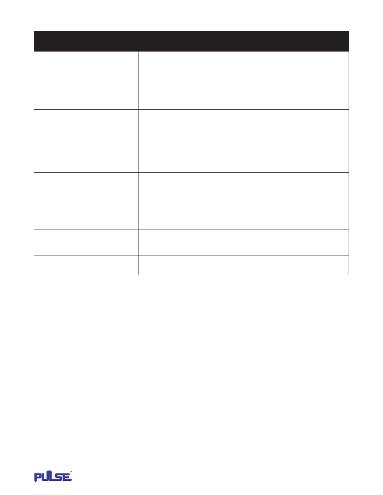
TROUBLESHOOTING CHART
Symptom Corrective Action
Prompted Message: Pulse monitor could not
be read. Check cable connections and/or 9V battery
located in the computer interface before attempting
to reconnect.
Prompted Message: This card is blank, no
records have been written to it yet; data displayed
is not accurate.
False motor trips. Example: Thermal trip in down
direction for hoist motion.
Event column of the data grid is blank. When the storage of events has reached memory capacity, a blank event is produced to signify the overwriting
Event has been recorded with a 1971 date stamp
after the date/time has been set on the card.
Motor Starts field equals 4294967295 and the Run
Time (Hours) field equals 1193046.5
1. Check to make sure the USB connections and/or serial connections are secure.
2. Make sure the computer interface has a 9V battery installed and that the battery is good.
3. Make sure printed circuit board in the computer interface was not inadvertently switched around when
the 9V battery was installed. Labeled connectors on printed circuit board must match interface labeling.
Ie: Connect to Computer or Connect to monitor card
4. Replace 9-wire serial cables. If the problem still exists, replace the computer interface.
If the card is new, upon connection you will get this message. Once the Pulse monitor card begins
accumulating data, the message will disappear.
Check K1 or K2 input of Pulse card for floating voltage. Example: If motor is moving in down direction,
K1 and K2 should read 0 V. If K1 or K2 reads other than 0 V, check all control transformers to verify they
have a common ground. Provide common ground as necessary.
of older events. A blank event will occur in both the current and history data. Disregard as an actual event.
The date indicates that as power was applied to terminal 91 on the monitor card, voltage was already present
on either terminal K1,K2,0A or 1A, then removed within 1 second of power being applied to terminal 91.
In the first second of turning on power, avoid applying a run command.
The card has not accumulated a total of 16 motor starts which is required for the Motor Starts and Run Time
fields to update. Accumulate a minimum of 16 motor starts before attempting to read card data.
Data not downloading Check com port on adaptor and pulse monitor software.
MONITOR
16
P/N: 11817503 REV. AA June 2014
Page 17
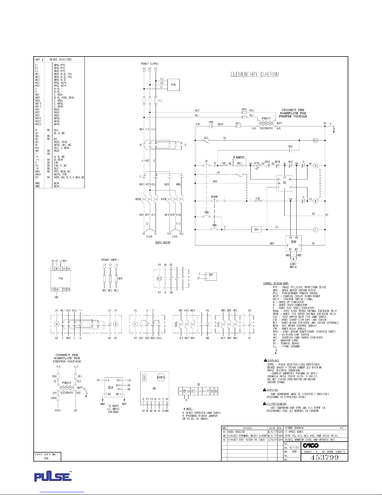
APPENDIX 1
WIRING DIAGRAMS
2-Speed Global Series 3, with geared limit switch, motor thermal switch, thermal overload relays and overcapacity limit switch�
MONITOR
17
Columbus McKinnon Corporation
Hoist & Rigging - Americas
Amherst, NY USA
P/N: 11817503 REV. AA June 2014
Page 18
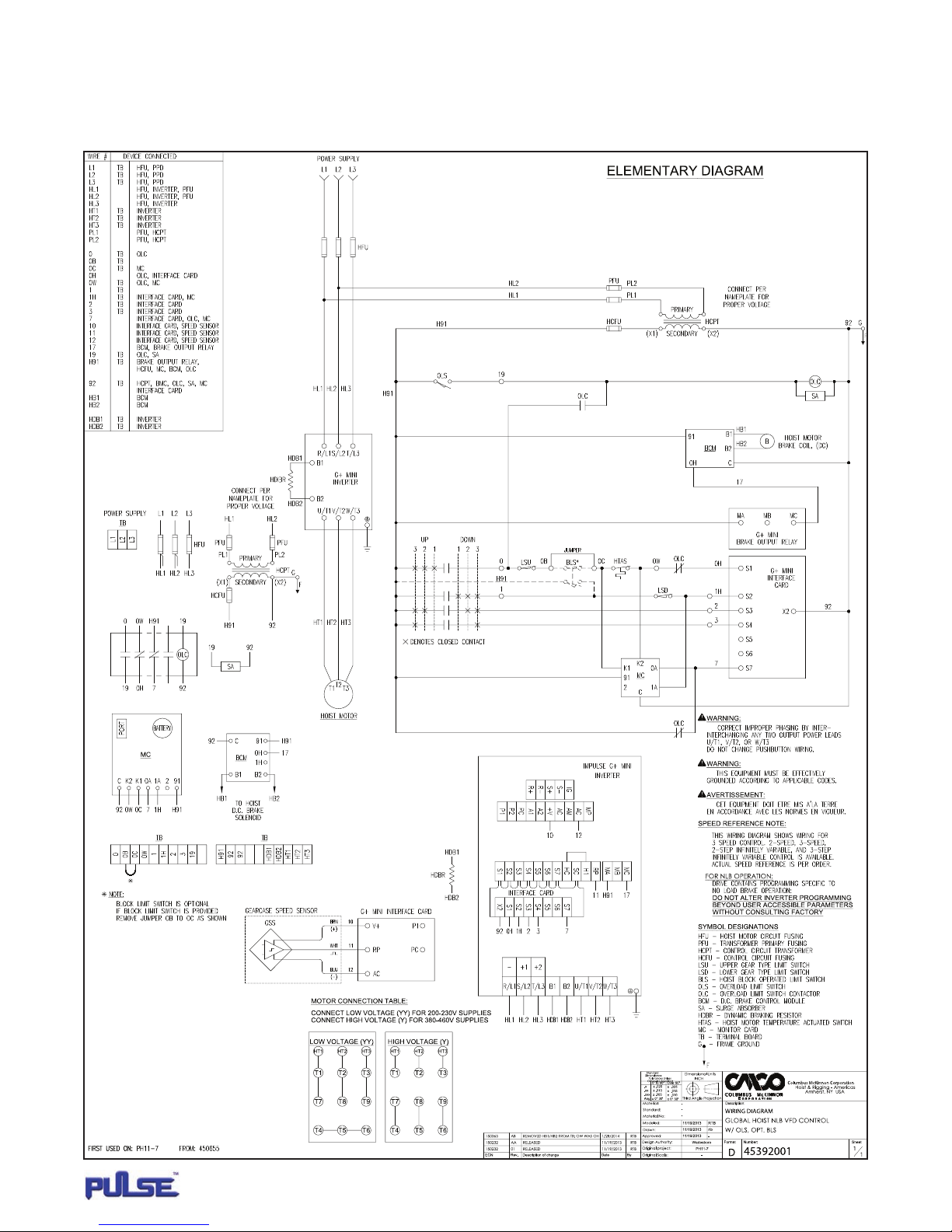
APPENDIX 1 (CONTINUED)
WIRING DIAGRAMS
Global Series 3 with MAGNETEK G+ Mini variable frequency drive, geared limit switch, motor thermal switch and overcapacity limit switch.
MONITOR
18
P/N: 11817503 REV. AA June 2014
Page 19
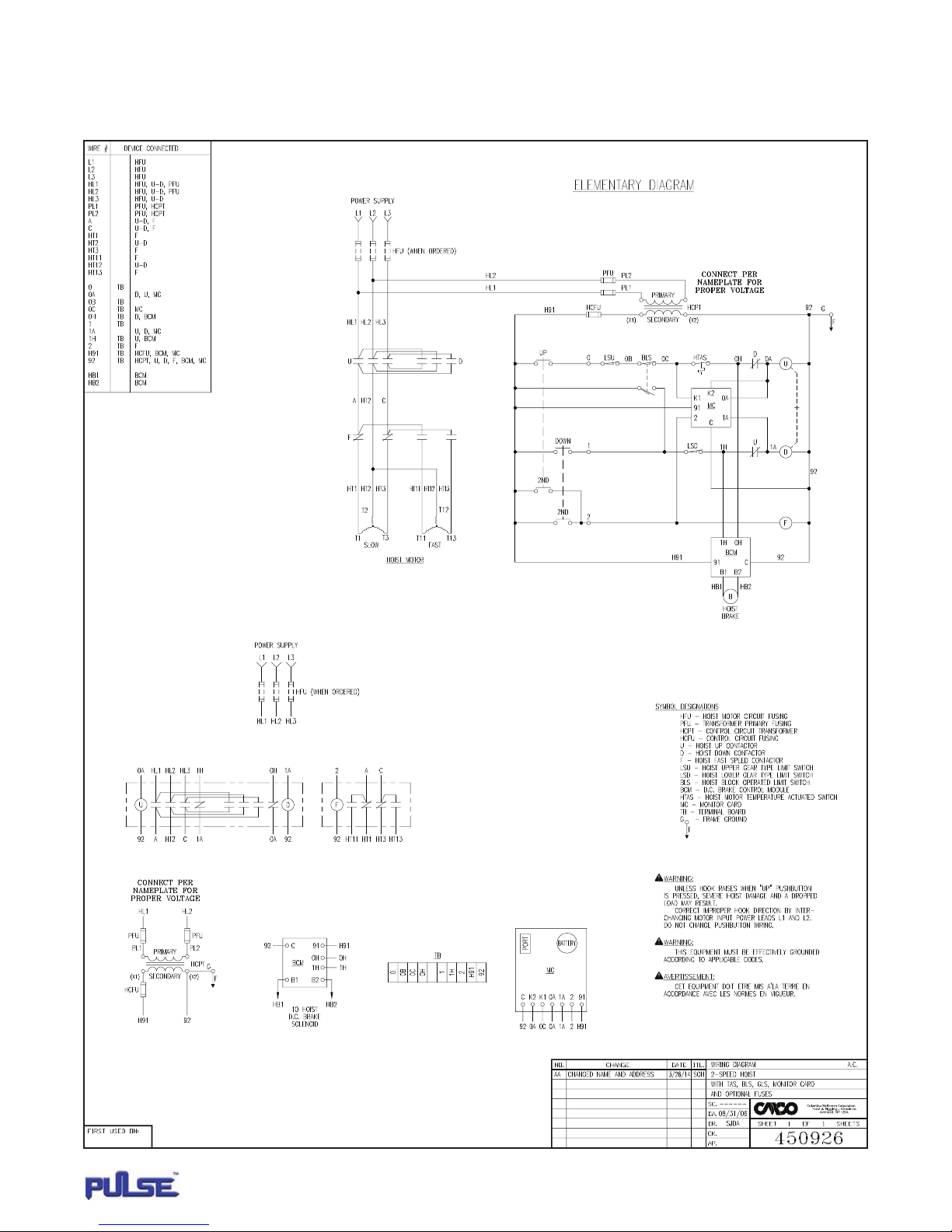
APPENDIX 1 (CONTINUED)
WIRING DIAGRAMS
2-Speed 700 Series hoist with geared limit switch, block limit switch and motor thermal switch�
MONITOR
19
P/N: 11817503 REV. AA June 2014
Page 20
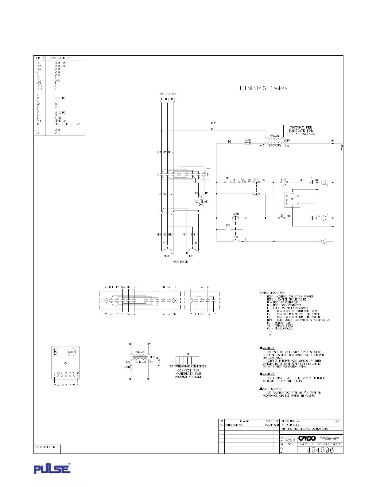
APPENDIX 1 (CONTINUED)
WIRING DIAGRAMS
2-Speed 800 Series hoist with geared limit switch, block limit switch and motor thermal switch�
MONITOR
20
P/N: 11817503 REV. AA June 2014
Page 21
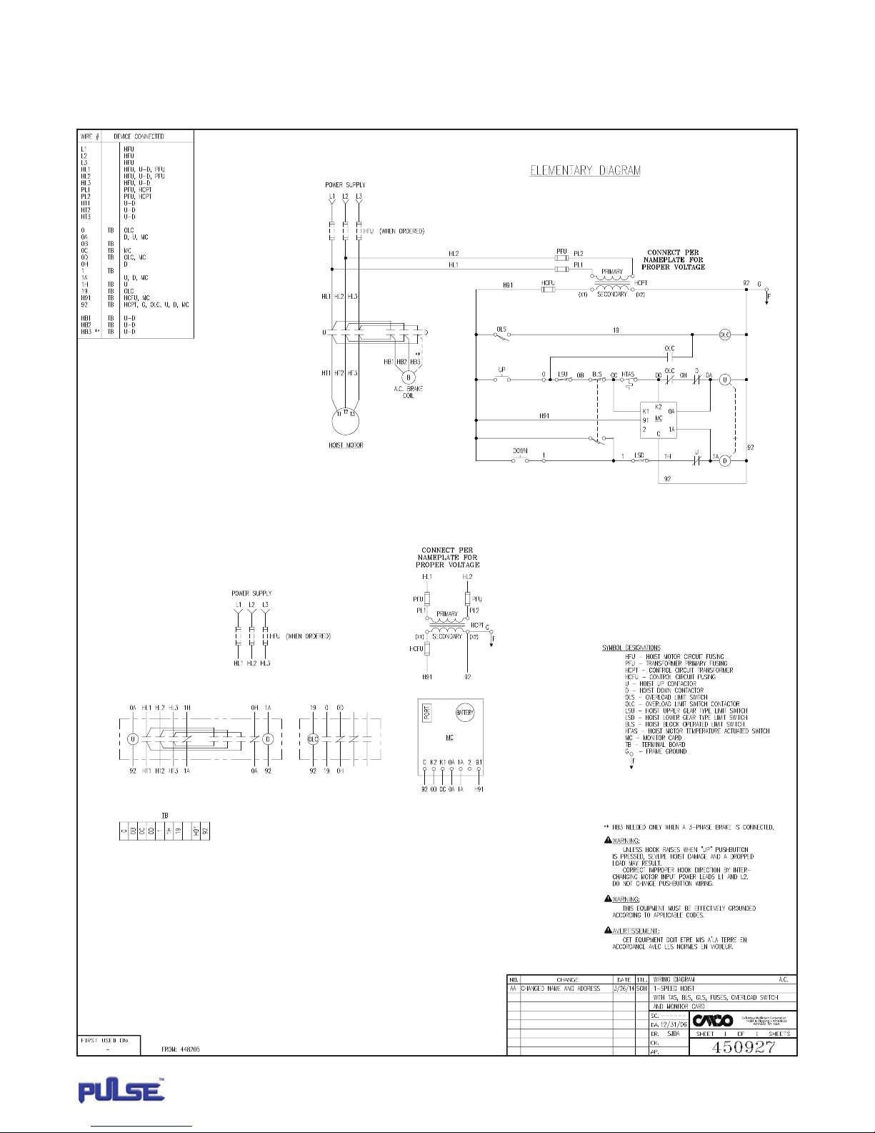
APPENDIX 1 (CONTINUED)
WIRING DIAGRAMS
1-Speed Cable King with geared limit switch, block limit switch, motor thermal switch and overcapacity limit switch�
MONITOR
21
P/N: 11817503 REV. AA June 2014
Page 22
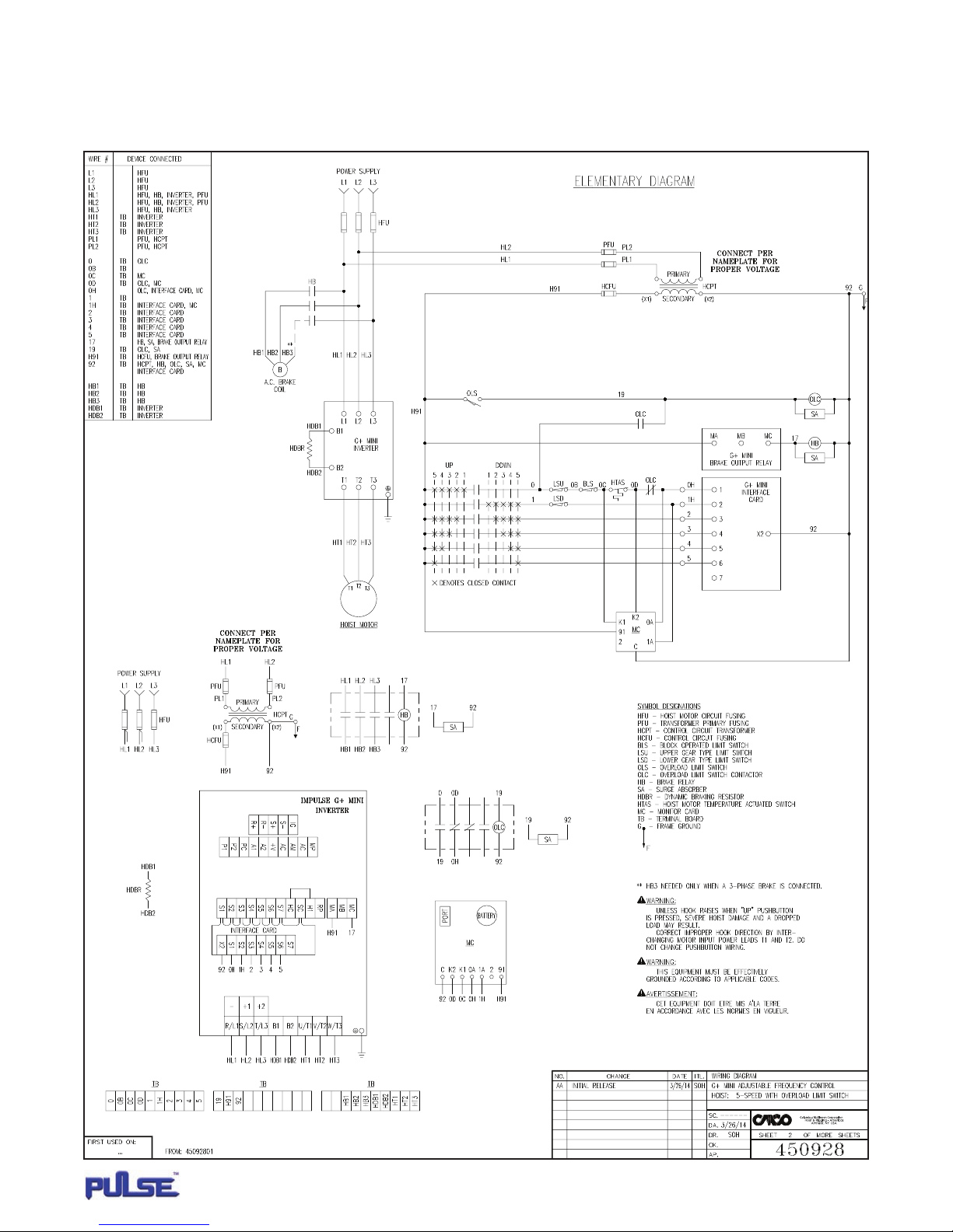
APPENDIX 1 (CONTINUED)
WIRING DIAGRAMS
Cable King with MAGNETEK G+ Mini variable frequency drive, geared limit switch, block limit switch,
motor thermal switch and overcapacity limit switch�
MONITOR
22
P/N: 11817503 REV. AA June 2014
Page 23
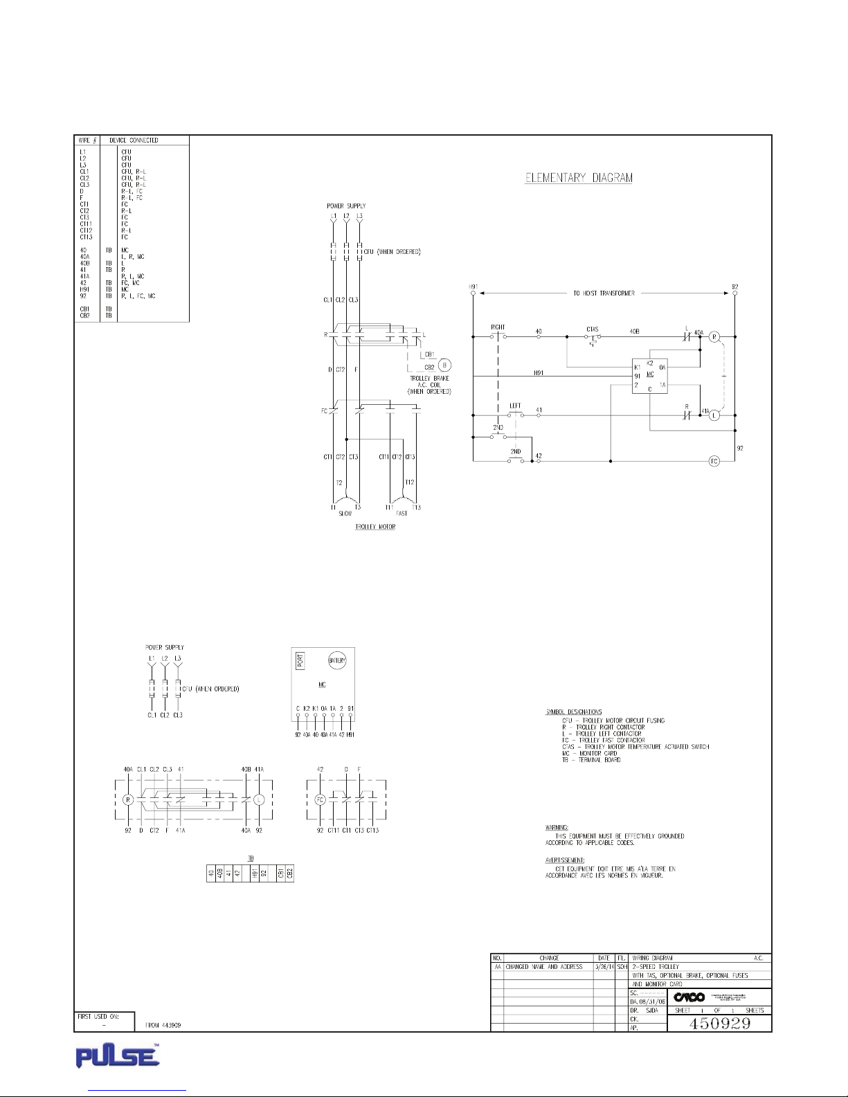
APPENDIX 1 (CONTINUED)
WIRING DIAGRAMS
2-Speed trolley with motor thermal switch�
MONITOR
23
P/N: 11817503 REV. AA June 2014
Page 24

APPENDIX 2
VOLTAGE MEASUREMENT ACCURACY
While the Pulse monitor itself is capable of +/-5% voltage measurement accuracy, two additional factors may further decrease accuracy.
Motor voltage is calculated using the control voltage powering the Pulse monitor� This calculation is based on the ideal ratio of the control
transformer (primary voltage to secondary voltage)� Any variation in the control transformer ratio will consistently skew the motor voltage
data� Additionally, this voltage measurement is made at the point where the Pulse monitor is connected� If this point is significantly removed
from the motor being monitored, a noticeable voltage drop may exist� The user is cautioned to consider both these contributing factors while
interpreting the stored voltage data�
REPLACEMENT PARTS
Description Part Number
Serial Port to USB Adaptor Cable 23596401
Serial Extension Cable 23386403
CUSTOMER SERVICE
For Customer Service, please call 1-800-888-0895
MONITOR
24
P/N: 11817503 REV. AA June 2014
Page 25

NOTES
___________________________________________________________________
___________________________________________________________________
___________________________________________________________________
___________________________________________________________________
___________________________________________________________________
___________________________________________________________________
___________________________________________________________________
___________________________________________________________________
___________________________________________________________________
___________________________________________________________________
___________________________________________________________________
___________________________________________________________________
___________________________________________________________________
___________________________________________________________________
___________________________________________________________________
___________________________________________________________________
___________________________________________________________________
___________________________________________________________________
___________________________________________________________________
___________________________________________________________________
___________________________________________________________________
___________________________________________________________________
MONITOR
25
P/N: 11817503 REV. AA June 2014
Page 26

NOTES
___________________________________________________________________
___________________________________________________________________
___________________________________________________________________
___________________________________________________________________
___________________________________________________________________
___________________________________________________________________
___________________________________________________________________
___________________________________________________________________
___________________________________________________________________
___________________________________________________________________
___________________________________________________________________
___________________________________________________________________
___________________________________________________________________
___________________________________________________________________
___________________________________________________________________
___________________________________________________________________
___________________________________________________________________
___________________________________________________________________
___________________________________________________________________
___________________________________________________________________
___________________________________________________________________
___________________________________________________________________
MONITOR
26
P/N: 11817503 REV. AA June 2014
Page 27

NOTES
___________________________________________________________________
___________________________________________________________________
___________________________________________________________________
___________________________________________________________________
___________________________________________________________________
___________________________________________________________________
___________________________________________________________________
___________________________________________________________________
___________________________________________________________________
___________________________________________________________________
___________________________________________________________________
___________________________________________________________________
___________________________________________________________________
___________________________________________________________________
___________________________________________________________________
___________________________________________________________________
___________________________________________________________________
___________________________________________________________________
___________________________________________________________________
___________________________________________________________________
___________________________________________________________________
___________________________________________________________________
MONITOR
27
P/N: 11817503 REV. AA June 2014
Page 28

140 John James Audubon Parkway • Amherst, New York 14228-1197
1-800-888-0985 • Fax 716-689-5644 • www.cmworks.com
© 2014 Columbus McKinnon Corporation. All Rights Reserved.
NOTE: Pulse is not a trademark of Columbus McKinnon Corporation. P/N: 11817503 REV. AA June 2014
 Loading...