

Columbus McKinnon Coffing JLC Series, Coffing JLC0516, Coffing JLC0232, Coffing JLC2016, Coffing JLC1032 Operating, Maintenance & Parts Manual
...Page 1
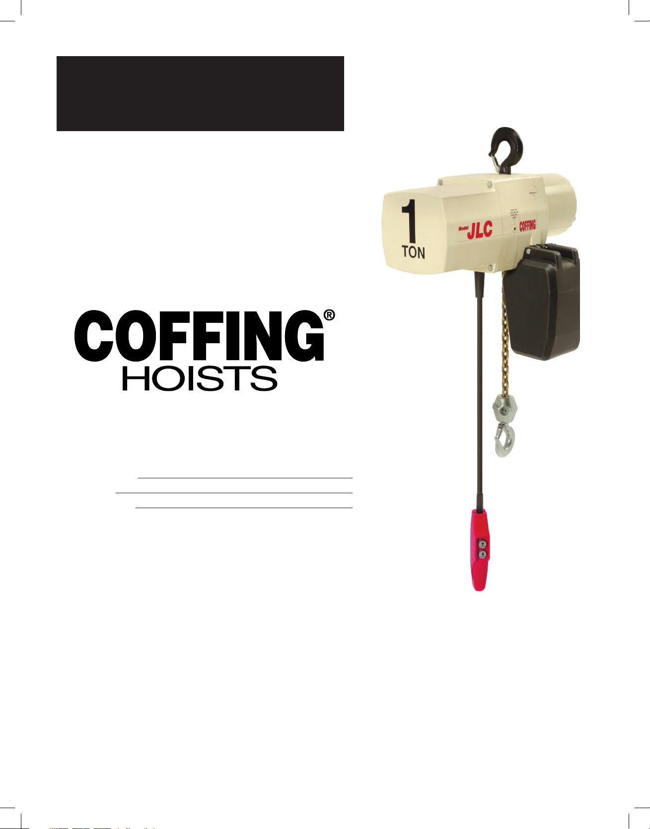
OPERATING, MAINTENANCE
& PARTS MANUAL
ELECTRIC CHAIN
JLC SERIES
Before installing hoist, fill in the information below.
Model Number.
Serial No.
Purchase Date
Please provide Serial Number when ordering parts.
MODEL NUMBERS:
JLC0232, JLC0516, JLC0532, JLC1016,
JLC1032, JLC2016, JLC4008
For JLCET models refer to this manual
and ETB680-1 for trolley information.
Follow all instructions and warnings for inspecting,
maintaining and operating this hoist.
The use of any hoist presents some risk of personal injury
or property damage. That risk is greatly increased if proper
instructions and warnings are not followed. Before using
this hoist, each operator should become thoroughly familiar
with all warnings, instructions and recommendations in this
manual. Retain this manual for future reference and use.
Forward this manual to hoist operator. Failure to operate
equipment as directed in the manual may cause injury.
Should you have any questions regarding this product,
please call Cofng Hoists at (800) 477-5003.
Assembled in USA with Imported and Domestic Components
JLC680-2 Rev AA April 2019
Page 2

COFFING HOIST PARTS AND SERVICES ARE AVAILABLE IN THE UNITED
STATES AND IN CANADA
As a COFFING Hoist and Trolley user you are assured of reliable repair and parts services through a
network of Master Parts Depots and Service Centers that are strategically located in the United States
and Canada. These facilities have been selected on the basis of their demonstrated ability to handle all
parts and repair requirements promptly and efciently. To quickly obtain the name of the Master Parts
Depot or Service Center located nearest you, call (800) 888-0985, Fax: (716) 689-5644,
visit www.cmworks.com.
LAS PIEZAS Y REPARACIONES DE LOS POLIPASTOS DE COFFING
ESTÁN ASEGURADAS EN ESTADOS UNIDOS Y CANADÁ
Como usuario de un polipasto y carro de COFFING le aseguramos cualquier reparación o la
disponibilidad de cualquier pieza de repuesto a través de una red de almacenes de piezas de repuesto y
centros de servicio situados estratégicamente en Estados Unidos y Canadá. Estas instalaciones se han
seleccionado en base a su capacidad demostrada en la reparación de equipos y suminstro de piezas de
repuesto de forma rápida y ecaz. Para obtener la dirección del almacén de piezas de repuesto o del
centro de servicio más cercano, llame al teléfono (800) 888-0985. Fax: (716) 689-5644, visita
www.cmworks.com (sólo en Estados Unidos y Canadá).
LE SERVICE DE RÉPARATION ET DE PIÈCES POUR PALANS COFFING
EST DISPONIBLE AUX ÉTATS-UNIS ET AU CANADA
Soyez assurés qu'en temps d'utilisateur de palan et treuil COFFING, d'un service de réparation et de
pièces able par l'entremise d'un réseau de Centres de service et de Dépôts de pièces maîtresses qui
sont stratégiquement situés aux États-Unis et au Canada. Ces établissements ont été sélectionnés sur
une base de leur habileté démontrée à s'occuper promptement et efcacement des besoins de réparation
de pièces. Appelez le (800) 888-0985, Fax: (716) 689-5644, visite www.cmworks.com pour obtenir
rapidement le nom du dépôt de pièces maîtresses ou du centre de service situé le plus près.
Page 3
JLC680-2 Rev AA April 2019
Improper operation of a hoist can create a potentially
hazardous situation which, if not avoided, could result in
death, or serious injury. To avoid such a potentially hazardous
situation, THE OPERATOR SHALL:
1. NOT operate a damaged, malfunctioning or unusually
performing hoist.
2. NOT operate the hoist until you have thoroughly read and
understood tmanufacturer’s Operating and Maintenance
Instructions or Manuals.
3. NOT operate a hoist which has been modied without the
manufacturer’s approval or without certication that it is in
conformity with ANSI/ASME B30 volumes.
4. NOT lift more than rated load for the hoist.
5. NOT use hoist with twisted, kinked, damaged,
or worn load chain.
6. NOT use the hoist to lift, support, or transport people.
7. NOT lift loads over people..
8. NOT operate a hoist unless all persons are and remain
clear of the supported load.
9. NOT operate unless load is centered under hoist.
10. NOT attempt to lengthen the load chain or repair damaged
load chain.
11. Protect the hoists load chain from weld splatter or other
damaging contaminants.
12. NOT operate a hoist when it is restricted from forming a
straight line from hook to hook in the direction of loading.
13. NOT use load chain as a sling or wrap load chain around load.
14. NOT apply the load to the tip of the hook or to the hook latch.
15. NOT apply load unless load chain is properly seated in the
chain sprocket(s).
16. NOT apply load if bearing prevents equal loading on all load
supporting chains.
17. NOT operate beyond the limits of the load chain travel.
18. NOT leave load supported by the hoist unattended unless
specic precautions have been taken.
19. NOT allow the chain or hook to be used as an electrical or
welding ground.
20. NOT allow the chain or hook to be touched by a live
welding electrode.
21. NOT remove or obscure the warnings on the hoist.
22. NOT operate a hoist on which the safety placards or decals
are missing or illegible.
23. NOT operate a hoist unless it has been securely attached to
a suitable support.
24. NOT operate a hoist unless load slings or other approved
single attachments are properly sized and seated in the
hook saddle.
25. Take up slack carefully - make sure load is balanced and
load holding action is secure before continuing.
26. Shut down a hoist that malfunctions or performs unusually
and report such malfunction.
27. Make sure hoist limit switches function properly.
28. Warn personnel of an approaching load.
Improper operation of a hoist can create a potentially
hazardous situation which, if not avoided, could result
in minor or moderate injury. To avoid such a potentially
hazardous situation, THE OPERATOR SHALL:
1. Maintain a rm footing or be otherwise secured when
operating the hoist.
2. Check brake function by tensioning the hoist prior
to each lift operation.
3. Use hook latches. Latches are to retain slings, chains, etc.
under slack conditions only.
4. Make sure the hook latches are closed and not supporting
any parts of the load.
5. Make sure the load is free to move and will clear all
obstructions.
6. Avoid swinging the load or hook.
7. Make sure hook travel is in the same direction as shown
on the controls.
8. Inspect the hoist regularly, replace damaged or worn parts,
and keep appropriate records of maintenance
9. Use Cofng Hoists recommended parts when repairing
the unit.
10. Lubricate load chain per hoist recommendations.
11. NOT use the hoist’s overload limiting clutch to measure load.
12. NOT use limit switches as routine operating stops. They are
emergency devices only..
13. NOT allow your attention to be diverted from operating
the hoist.
14. NOT allow the hoist to be subjected to sharp contact with
other hoists, structures, or objects through misuse.
15. NOT adjust or repair the hoist unless qualied to perform
such adjustments or repairs.
SAFETY PRECAUTIONS
Each Cofng JLC Series Electric Chain Hoist is built in accordance
with the specications contained herein and at the time of
manufacture complies with our interpretation of applicable
sections of *American Society of Mechanical Engineers Code
(ASME) B30.16 “Overhead Hoists,” the National Electrical Code
(ANSI/NFPA 70) and the Occupational Safety and Health Act
(OSHA). Since OSHA states the National Electrical Code applies to
all electric hoists, installers are required to provide current overload
protection and grounding on the branch circuit section in keeping
with the code. Check each installation for compliance with the
application, operation and maintenance sections of these articles.
*Copies of this standard can be obtained from
ASME Order Department, 22 Law Drive, PO Box 2300,
Faireld, NJ 07007- 2300, U.S.A., www.asme.org, 800-843-2763.
1
Page 4
JLC680-2 Rev AA April 2019
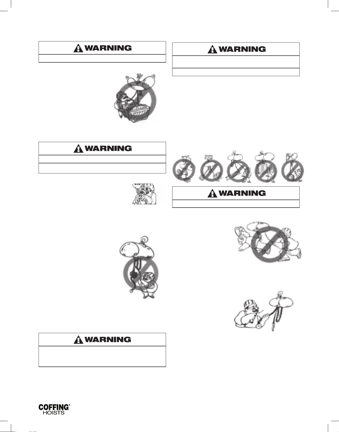
HOIST SAFETY IS UP TO YOU...
DO NOT LIFT MORE THAN RATED LOAD.
CHOOSE THE RIGHT HOIST FOR THE JOB...
Choose a hoist with the capacity for
the job. Know the capacities of your
hoists and the weight of your loads.
Then match them.
The application, the size and type
of load, the attachments to be used
and the period of use must also be
taken into consideration in selecting
the right hoist for the job.
Remember, the hoist was
designed to ease our burden and
carelessness not only endangers the
operator, but in many cases, a valuable load.
DO NOT OPERATE DAMAGED OR MALFUNCTIONING HOIST
DO NOT OPERATE WITH TWISTED, KINKED, OR
DAMAGED CHAIN.
INSPECT
All hoists should be visually inspected before
use, in addition to regular, periodic maintenance
inspections.
Inspect hoists for operations warning notices and
legibility.
Deciencies should be noted and brought to the attention of
supervisors. Be sure defective hoists are tagged and taken out of
service until repairs are made.
Under no circumstances should you
operate a malfunctioning hoist.
Check for gouged, twisted,
distorted links and foreign material.
Do not operate hoists with twisted,
kinked, or damaged chain links.
Load chain should be properly
lubricated.
Hooks that are bent, worn, or whose
openings are enlarged beyond
normal throat opening should not
be used. If latch does not engage
throat opening of hook, hoist should
be taken out of service.
Chains should be checked for
deposits of foreign material which may be carried into the hoist
mechanism.
Check brake for evidence of slippage under load.
DO NOT PULL AT AN ANGLE. BE SURE HOIST AND LOAD ARE
IN A STRAIGHT LINE.
DO NOT USE LOAD CHAIN AS A SLING.
USE HOIST PROPERLY
Be sure hoist is solidly held in the uppermost part of the support
hook arc.
Be sure hoist and load are in a straight line.
Do not pull at an angle.
Be sure load is hooked securely. Do not tip load the hook. Do not
load hook latch. Hook latch is to prevent detachment of load under
slack chain conditions only.
Do not use load chain as a sling. Such usage damages the chain
and lower hook.
Do not operate with hoist head resting against any object. Lift the
load gently. Do not jerk it.
.
DO NOT LIFT PEOPLE OR LOADS OVER PEOPLE
LIFT PROPERLY
Do not lift co-workers with a
hoist.
Make sure everyone is clear of
the load when you lift.
Do not remove or obscure
operational warning notices.
MAINTAIN PROPERLY
CLEANING
Hoists should be kept clean and free of dust, dirt, moisture, etc.,
which will in any way affect the operation or safety of the equipment.
LUBRICATION
Chain should be properly lubricated.
AFTER REPAIRS
Carefully operate the hoist
before returning it to full service.
Violations of any of the warnings listed may result in serious
personal injury to the operator or nearby personnel by nature
of released load or broken hoist components.
2
Page 5

JLC680-2 Rev AA April 2019
FOREWARD
This manual contains important information to help you properly install, operate and maintain your hoist for maximum performance, economy
and safety.
Please study its contents thoroughly before putting your hoist into operation. By practicing correct operating procedures and by carrying out
the recommended preventive maintenance suggestions, you will experience long, dependable and safe service. After you have completely
familiarized yourself with the contents of this manual, we recommend that you carefully le it for future reference. The information herein is
directed to the proper use, care and maintenance of the hoist and does not comprise a handbook on the broad subject of rigging.
Rigging can be dened as the process of lifting and moving heavy loads using hoists and other mechanical equipment. Skill acquired through
specialized experience and study is essential to safe rigging operations. For rigging information, we recommend consulting a standard
textbook on the subject.
TABLE OF CONTENTS
SAFETY PRECAUTIONS
Operating and Safety Procedures ..................................................... 2
Foreword ........................................................................................... 3
GENERAL INFORMATION
Safety Standards ................................................................................ 4
Basic Hoist Data ................................................................................. 4
Application Information ...................................................................... 4
Warranty ............................................................................................. 4
SPECIFICATIONS ............................................................................. 5
INSTALLLATION
Chain Container .................................................................................. 5
Installation of Standard Chain Container ........................................... 6
OPERATION
Overload Limiting Protection .............................................................. 7
MAINTENANCE
Inspections ......................................................................................... 7
Lowering Without Power .................................................................... 7
Hooks ................................................................................................. 7
Chains ................................................................................................ 8
Limit Switch Adjustment .................................................................... 9
Brake .................................................................................................. 9
Hoist Controls ................................................................................... 10
Wiring ............................................................................................... 10
Lubrication ........................................................................................ 10
Hoist Repairs .................................................................................... 10
Power Cord Precautions with 1-Phase Hoists ................................. 12
TROUBLESHOOTING .................................................................... 13
WIRING ............................................................................................ 15
INSPECTION ................................................................................... 17
REPAIR PARTS
Ordering Information ........................................................................ 20
LIST OF TABLES
TABLE DESCRIPTION PAGE
1 Hoist Specications .......................................................... 5
2 Motor Amperage of 1-Speed Hoist Models ..................... 5
3 Motor Amperage of 2-Speed Hoist Models ..................... 5
4 Chain Containers .............................................................. 6
5 Recommended Conductor Sizes for 1-Phase Hoist ...... 12
6 Troubleshooting .........................................................13-14
LIST OF ILLUSTRATIONS
FIG. DESCRIPTION PAGE
1 Installing Chain Container Assembly ................................ 6
2 Hook Inspection ................................................................. 7
3 Limit Switch Assembly....................................................... 8
4 Chain Replacement Diagram ............................................. 9
5 Brake Assembly .............................................................. 10
6 Electrical Panel Removed ............................................... 10
7 Assembled Gearing ......................................................... 11
8a Single Chain Lub Oriented ............................................... 12
8b Single Chain Hook Orientation ........................................12
8c Double Chain Hook Orientation ....................................... 12
9a Wiring Diagram for 115/230V 1 Phase Models ................ 15
9b Wiring Diagram for 1- Speed, 230/460V -
9c Wiring Diagram for 1- Speed, 208V & 575V
9d Wiring Diagram for 2-Speed, 3 Phase Models ............... 16
10a Recommended Inspection and Maintenance Checklist . 18
10b Recommended Inspector's Report ................................19
11 Recommended Lubrication Schedule ............................ 19
12 Basic Hoist ......................................................................21
13 Hoist Motor, 115/230V — 1 Phase ................................. 22
14 Hoist Motor — 3 Phase ..................................................23
15 Brake & Solenoid Parts ................................................... 24
16 Electrical Parts — 1 Speed Models ................................ 25
17 Electrical Parts — 2 Speed Models ................................ 26
18 1 Speed Pushbutton Station ..........................................27
19 2 Speed Pushbutton Station ..........................................28
20 Cofng Rocket Universal Pendant Control ................29-30
21 Limit Switch Assembly ....................................................31
22 Long Lift Limit Switch Parts ............................................32
23 Transmission ..............................................................33-34
24 Chaining Parts ...........................................................35-36
3 Phase Models .............................................................. 15
3 Phase Models .............................................................. 16
3
Page 6
JLC680-2 Rev AA April 2019
SECTION I — INTRODUCTION
1-1 GENERAL INFORMATION
INSPECTION
This manual provides information for the safe operation and
maintenance of Cofng
or maintaining these hoists should be familiar with the information
contained herein. Adherence to the precautions, procedures, and
maintenance practices described should ensure long reliable
operation. Suggestions for improvements to this manual
are solicited.
To safeguard against the possibility of personal injury or property
damage, follow the recommendations and instructions of this
manual. This manual contains important information for the correct
installation, operation, and maintenance of this equipment. All
persons involved in the installation, operation, and maintenance of
this equipment should be thoroughly familiar with the contents of this
manual. Keep this manual for reference and further use.
®
JLC Series Hoists. All persons operating
10. Before using the hoist, the operator should be certain that all
personnel are clear.
11. Do not operate hoist with loads exceeding its rated capacity.
12. Supporting frames or beams used as a hoist hanger must have
a greater load capacity than the hoist.
13. Do not attempt to operate the hoist beyond normal maximum
lift range.
14. Align hoist for a straight line pull. Avoid side pull or end pull.
15. Do not operate hoist with twisted or damaged chain.
16. Do not operate a damaged or malfunctioning hoist until
necessary adjustments or repairs have been made.
17. Do not use hoist to lift people or to carry loads over people.
18. Do not leave a load suspended in the air unattended.
19. Always remove load before making repairs.
20. Do not remove or obscure capacity or warning decals
1-3 BASIC HOIST DATA
The basic hoist models covered by this manual are listed in
Table 1.
To avoid personal injury:
Do not use the equipment shown in this manual to lift, support, or
otherwise transport people, or to suspend unattended loads over
people.
1-2 SAFETY STANDARDS
All persons concerned with the installation, operation, inspection
and maintenance of these hoists are urged to read ASME B30.16.
That Standard contains valuable guidelines concerning practices
designed to minimize hazards associated with the use of overhead
hoisting equipment. ASME B30.16 also contains detailed procedures
for establishing hoist inspection and maintenance programs and can
be of signicant assistance in maintaining compliance with OSHA
regulations.
1. Follow all local electrical and safety codes, as well as the
National Electrical Code (NEC) and the Occupational Safety
and Health Act (OSHA) in the United States.
2. Hoist must be securely and adequately grounded. Hoist
power cable is provided with an additional lead (green) for
grounding purposes.
Always disconnect power source before working on or near
a hoist or its connected load. If the power disconnect point
is out of sight, lock it in the open position and tag to prevent
unexpected application of power.
3. Be careful when touching the exterior of an operating motor;
it may be hot enough to be painful or cause injury. With
modern motors this condition is normal if operated at rated
load and voltage (modern motors are built to operate at higher
temperatures).
4. Protect the power cable and control cable from coming in
contact with sharp objects.
5. Do not kink power cable and control cable and never allow the
cable to come in contact with oil, grease, hot surfaces,
or chemicals.
6. Make certain that the power source conforms to the
requirements of your equipment.
7. Inspect the unit daily before operating the hoist.
8. Cluttered areas and benches invite accidents.
9. The operator should not engage in any practice which will
divert his attention while operating the hoist.
1-4 APPLICATION INFORMATION
This hoist is intended for general industrial use in the lifting and
transporting of freely suspended material loads within its rated
load. Prior to installation and operation, the user should review his
application for abnormal environmental or handling conditions and to
observe the applicable recommendations as follows:
a. Adverse Environmental Conditions. Do not use the hoist
in areas containing ammable vapors, liquids, gases or
any combustible dusts or bers. Refer to Article 500 of
The National Electric Code. Do not use this hoist in highly
corrosive, abrasive or wet environments. Do not use
this hoist in applications involving extended exposure to
ambient temperatures below -10°F or above 130°F.
b. Lifting of Hazardous Loads. This hoist is not
recommended for use in lifting or transporting hazardous
loads or materials which could cause widespread damage if
dropped. The lifting of Ioads which could explode or create
chemical or radioactive contamination if dropped requires
fail-safe redundant supporting devices which are not
incorporated into this hoist.
c. Lifting of Guided Loads. This hoist must not be used in the
lifting of guided loads, including dumbwaiters, non-riding
elevators and elevators. Such applications require additional
protective devices which are not incorporated into this
hoist. Refer to your state and local regulations governing
and the American National Safety Code for elevators,
dumbwaiters, escalators and moving walks (ASME A17.1).
1-5 WARRANTY
Every hoist is thoroughly inspected and tested prior to shipment
from the factory. Should any problems develop, return the complete
hoist prepaid to your nearest Cofng Authorized Warranty Repair
Station. If inspection reveals that the problem is caused by defective
workmanship or material, repairs will be made without charge and
the hoist will be returned, transportation prepaid.
This warranty does not apply where: (1) deterioration is caused by
normal wear, abuse, improper or inadequate power supply, eccentric
or side loading, overloading, chemical or abrasive actions, improper
maintenance or excessive heat; (2) problems resulted from repairs,
modications or alterations made by persons other than factory
or Cofng Authorized Warranty Repair Station personnel; (3) the
hoist has been abused or damaged as a result of an accident; (4)
repair parts or accessories other than those supplied by Cofng are
used on the hoist. Equipment and accessories not of the seller's
manufacture are warranted only to the extent that they are warranted
by the manufacturer. EXCEPT AS STATED HEREIN, COFFING
MAKES NO OTHER WARRANTIES, EXPRESS OR IMPLIED,
INCLUDING WARRANTIES OF MERCHANTABILITY AND FITNESS
FOR A PARTICULAR PURPOSE.
4
Page 7
JLC680-2 Rev AA April 2019
SECTION II — SPECIFICATIONS
Cofng JLC series electric chain hoists are rugged, portable hoists
that provide quick, precise lifting. The hoists are constructed of
tough, but lightweight, die cast aluminum alloy housings. An oil bath
transmission, equipped with heat-treated, alloy steel gears and an
overload limiting clutch, provides smooth and reliable operation.
With a pushbutton station that ts comfortably in one hand, the
operator can safely control the hoist while the other hand is free to
guide the load. The electrical controls use a low voltage circuit (24V
standard, 115V optional). Terminal blocks allow for easy voltage
conversions on dual-voltage models.
Other features that ensure the safe operation of Cofng electric
chain hoists include a magnetic disc brake that delivers sure
stopping and secure holding of the load. Adjustable upper and lower
limit switches regulate the load travel. As a standard, hooks are
supplied with safety latches. For additional safety, a chain stop is
attached to the slack end of the load chain.
Cofng electric chain hoists are designed and tested in accordance
with the American Society of Mechanical Engineers Code
B30.16, “Safety Standard for Overhead Hoists.” Hoists are built in
compliance with CSA, le number LR 44484. Made in U.S.A.
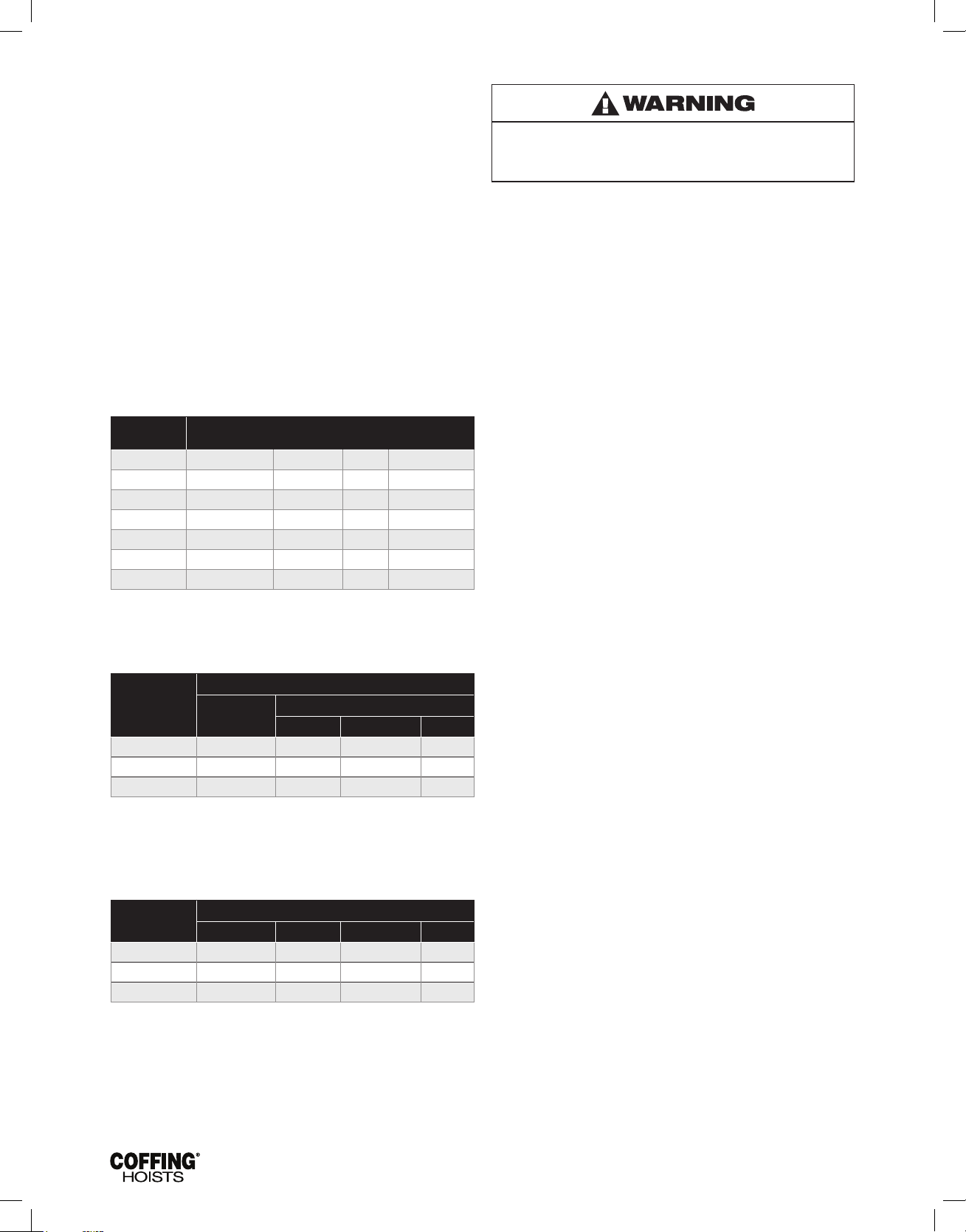
Table 1 - Hoist Specifications
Model
JLC0232 250 32 1/4 1/2 Single-Chained
JLC0516 500 16 1/2 Single-Chained
JLC0532 500 32 1/2 Single-Chained
JLC1016 1000 16 1/2 Single-Chained
JLC1032 1000 32 1 Single-Chained
JLC2016 2000 16 1 Single-Chained
JLC4008 4000 8 1 Double-Chained
*Note: JLCET models are equivalent to the corresponding JLC, but
are supplied with a push-type trolley. Reference in this manual to
JLC models also applies to JLCET models.
Hoist Capacity
(lbs)
Table 2 - Motor Amperage of 1-Speed Hoist Models
Hoist HP
1/4 N/A 1.9 1.7/.85 .7
1/2 8.4/4.2 2.3 2.1/1.05 .7
1 14.8/7.4* 4.6 3.9/1.95 1.6
* The 1HP, 115/230V models (JLC1032-1, JLC2016-1, JLC4008-1) must
have a dedicated power circuit rated for at least 20A, 125V when they
are wired for 115V. It is not unusual for these models to draw up to 20
amps at 115V when lifting at rated capacity depending on the quality of
the voltage source.
1-Phase
115/230V
Table 3 - Motor Amperage of 2-Speed Hoist Models
Hoist HP
(fast/slow)
0.25/0.083 2.0/1.9 2.2/2.2 0.9/0.9 0.64/0.71
0.5/0.17 3.8/3.2 3.7/3.0 1.35/1.25 1.15/1.05
1/0.33 4.6/5.8 5.0/3.5 2.25/1.55 2.1/1.4
NOTE: The above data is the nominal motor current at full load.
At full load, it is not unusual for the hoist to draw in excess of the
values listed when lifting. It is critical to ensure that the voltage at
the reversing contactor does not drop more than 10% below the
nominal voltage while lifting a load. Low voltage will result in higher
amp draw, damage to the hoist, and potential re hazards. Cofng
Hoists is not responsible for any damages caused by an inadequate
power source.
Full Load Amps for 3 Phase Only (fast/slow)
208v 230V 460V 575V
Lifting
Speed (fpm)
Full Load Amps
208V 230/460V 575V
HP Reeving
3-Phase
Failure to comply with Safety precautions outlined throughout
this manual can result in serious injuries or death. Before using
this hoist, each operator should become thoroughly familiar with
all warnings, instructions and recommendations in this manual.
SECTION III — INSTALLATION
1. Before installing the hoist, check the following:
a. Make sure all supporting structures and attaching devices
are strong enough to hold your intended loads. If in doubt,
consult a qualied structural engineer.
b. Provide proper branch circuit protection for the hoist as
recommended in the National Electrical Code.
c. The power supply should be plus or minus 10% of the
voltage specied on the motor nameplate. It is critical to
use adequate sized power cables, especially with 1- phase
hoists (See Table 5, page 11). Be sure dual voltage hoists
are connected or wired to correspond with your power
supply (See WIRING, page 9).
d. Installation area must provide operating conditions for the
operator including sufcient room for the operator and
other personnel to stand clear of the load at all times.
e. For installations where the slack chain hanging from the
unit may be objectionable or hazardous, the use of a chain
container is recommended (See CHAIN CONTAINER,
page 5).
2. JLCET models come with a Cofng ETB push-type trolley and
an adaptable suspension lug. ETB trolleys are made to run
on American Standard I-Beams and Wide Flange Beams with
ange widths up to 8". For assembly refer to the instructions
provided with the trolley. The hoist lug must be centered
with the sideplates (±1 washer). Due to the lug thickness, the
washer placement between each sideplate and the lug may
differ by 1 less washer than the generic instructions specify. For
installations where the trolley can not be slid onto the end of a
beam, leave the load pin nuts loose enough to get the wheels
around the beam ange. Check the ange width setting before
tightening the nuts to 125 ft-lbs. Be sure to have end stops on
your beam.
3. Before operating the hoist, be sure to observe the following:
a. ALWAYS DISCONNECT HOIST FROM POWER SUPPLY
before removing electrical cover or when making any
electrical connection in the hoist or pushbutton station.
b. The ground wire (green colored) of the power cable should
always be connected to a suitable ground by means of
a screw or clamp. An alligator clip does not make a safe
ground connection.
c. When installing a three-phase hoist, make only temporary
connections at the power source. Push the “UP” button
and observe the direction of the load block. If it raises, the
phasing is correct and permanent connections may be
made at the power source. If the load block lowers when
the “UP” button is pushed, release the button immediately
since the limit switches will not operate to protect the hoist
from over-travel. Reverse any two wires (except the green
ground wire) at the power source to correct the load hook
direction (phasing). Do not change connections in the hoist
or pushbutton assembly.
d. Make sure load chain is not twisted as it travels into
the hoist.
e. Operate hoist in a hanging position only. Hoist should
be permitted to align itself for a straight line pull. Do not
attempt to pull around corners.
f. Read ASME-B30.16 Safety Code for Hoists.
4. Lubricate the chain as necessary, see LUBRICATION, page 9.
5. Check the function of the limit switches. Before placing hoist in
operation, check limit switch settings. Operate pushbutton until
near stop point and inch into stop limit, both top and bottom. If
either switch is not correct, adjust according to LIMIT SWITCH
ADJUSTMENT, page 8.
5
Page 8
JLC680-2 Rev AA April 2019
CHAIN CONTAINER (OPTIONAL ACCESSARY)
Refer to Table 4.
For installations where the slack chain hanging from the hoist
may be objectionable or hazardous, the use of a chain container
is recommended.
Available chain containers include the standard containers designed
for lifts of up to 50 ft on single-chained hoists and 25 ft on doublechained hoists. For longer lifts, the JLC927-4 container is available.
For applications where a fabric bag is preferred, the JLC927-20F,
JLC927-35F and the JLC927-50F are all options.
Do not attempt to store more chain in chain container than
that specified in the table below. Failing to do so may cause
serious hoist damage and hazardous conditions that may
result in injury or death.
Instructions are provided with each of these chain containers and
must be adhered to closely to ensure a proper installation. To install
the long lift chain container or a fabric chain container, you must follow
instruction sheets provided with the chain container. The following
instructions are for the standard JLC927-1 chain container only..
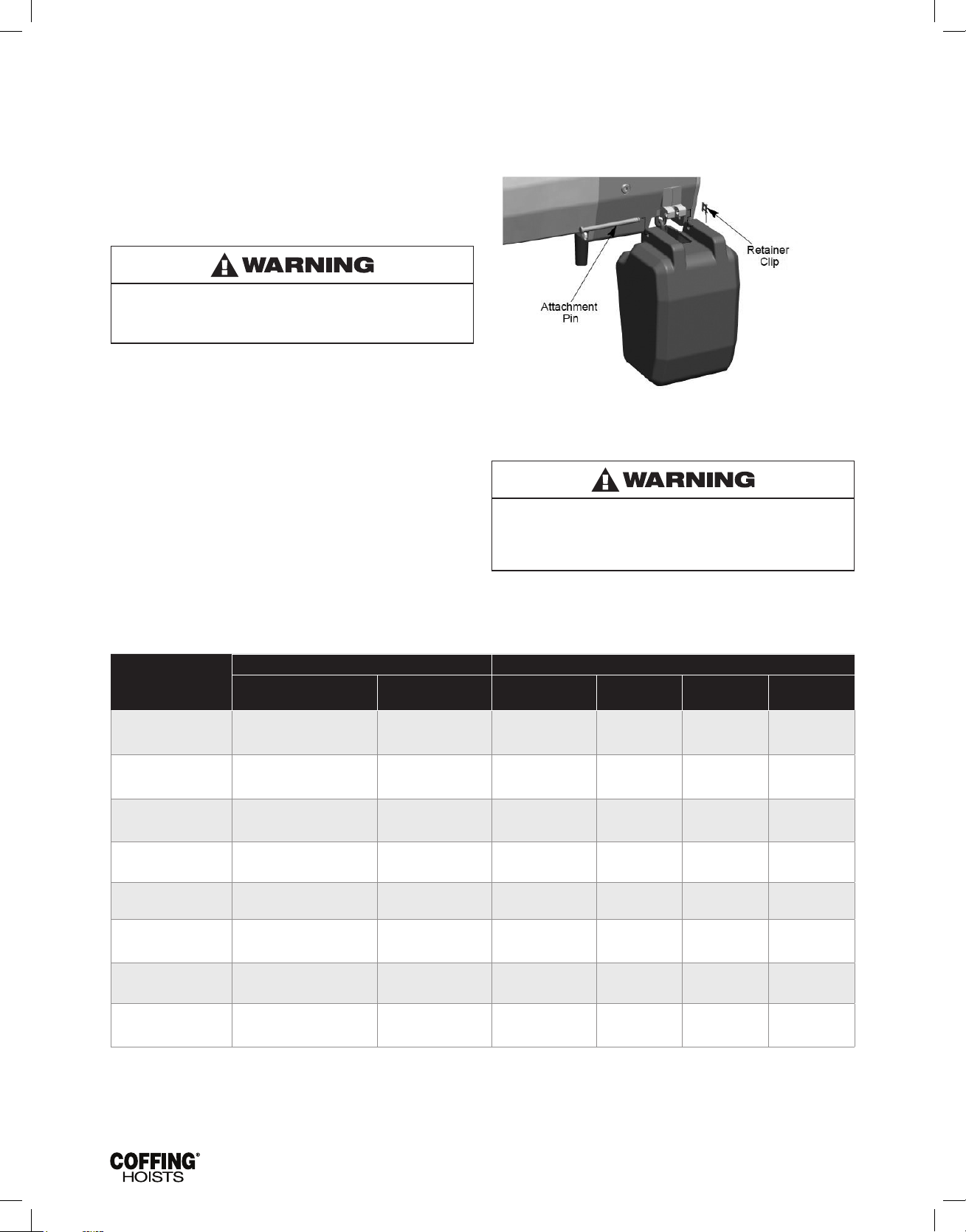
INSTALLATION OF STANDARD CHAIN
CONTAINER (JLC927-1)
Refer to Figure 1.
1. Remove retaining clip and attachment pin and let the slack
chain hang free.
2. Run load hook down to its lowest position. Place the slack end
of chain in chain container. Do not remove the chain stop.
3. Place chain container ush against housing with chain stripper
between top lugs. Insert long attachment pin and replace
retaining clip.
4. Feed the remainder of chain into container by operating hoist in
the “UP” direction to the top limit. This will permit the chain to
pile freely and prevent the chain from kinking, which may occur
if the chain is placed in the container by hand.
Figure 1 — Installing Chain Container Assembly
Load chain that is kept clean and lubricated is essential to the
safe operation of a hoist with a chain container. Failure to do
so may cause serious hoist damage, spillage of chain from
container, cross-linked chain resulting in dropped load and
other hazardous conditions that may result in injury or death.
Table 4 - Chain Containers
Recommended for Use With: Dimensions in Inches
Chain Container Model
JLC927-1* 1 Ton & Under 2 Ton
JLC927-2** 1 Ton & Under 2 Ton
JLC927-3** 1 Ton & Under 2 Ton
JLC927-4** 1 Ton & Under 2 Ton
JLC927-20F** 1 Ton & Under 2 Ton
JLC927-35F** 1 Ton & Under 2 Ton
JLC927-50F** 1 Ton & Under 2 Ton
JLC927-70F** 1 Ton & Under 2 Ton
*Standard container included with hoist with 20 ft max.,single line ot 10ft Max double line hoist only.
**All other chain containers sold separately.
Hoist Capacity Maximum Lift Container Material Width Length Depth
20
10
35
17
50
25
143
71
20
10
35
17
50
25
70
35
Molded Container 6 7/8” 6 1/2” 10 3/8”
Molded Container 6 1/2” 6 1/2” 15 3/4”
Molded Container 6 1/2” 6 1/2” 20 1/4”
Steel or Molded
Container
Open Weave Vinyl
Coated Polyester
Open Weave Vinyl
Coated Polyester
Open Weave Vinyl
Coated Polyester
Open Weave Vinyl
Coated Polyester
6 1/2" 6 1 /2" 34 "
7 1/2” 7 1/2” 16”
7 1/2” 7 1/2” 22
7 1/2” 7 1/2” 26
7 1/2” 7 1/2” 31
6
Page 9
JLC680-2 Rev AA April 2019
SECTION IV — OPERATION
4-1 GENERAL
This hoist is designed for safe operation within the limits of its rated
capacity. It is controlled by the “UP” and “DOWN” buttons of the
pushbutton station. Two-speed models utilize 2-step buttons, the
rst step for operating the slow speed and the second for the fast
speed. Although the Cofng JLC is built with many features to
ensure safety, it is a requirement that a hoist operator understands
safe lifting practices. The following points must be observed.
Do not allow load to come in contact with the chain container.
If this situation exists reset the “UP” limit switch so that the
hook block stops below the chain container (See LIMIT SWITCH
ADJUSTMENT, page 8).
1. Do not overload the hoist.
2. Do not make extreme side pulls with the hoist.
3. Operate the hoist only in a hanging position with
adequate support.
4. Do not “sling” the load hook and chain around the load.
Use an approved sling.
5. Be sure there are no twists in the load chain as it travels into
the hoist housing. This condition should be constantly checked
on double chain hoists because it is possible for the load block
to be “capsized” or turned over one or more times.
6. Before raising a load, always check to see that it is held
securely in the hook or sling chains, etc. Raise the load only
until the load chain is taut and then double check the rigging
before continuing to raise the load.
7. Do not stand beneath a load! Do not move a load in such
a manner as to endanger personnel.
SECTION V — MAINTENANCE
5-1. INSPECTIONS
A planned inspection routine should be established for this hoist
based upon frequency of use, severity of use, and environmental
conditions (Reference ASME Standard B30.16). Some inspections
should be made frequently (daily to monthly) and others periodically
(monthly to yearly). It is strongly recommended that an Inspection
and Maintenance Check List and an Inspector’s Report, similar
to those shown in Figures 10A and 10B, be used and led for
reference. All inspections should be performed or overseen by a
designated inspector. Special inspections should be made following
any signicant repairs or any operating occurrence leading one to
suspect that the hoist’s capability may have been impaired
5-2. LOWERING WITHOUT POWER
If the power fails with a load suspended, the hoist will automatically
stop. In an emergency the load can be lowered without power as
follows:
1. DISCONNECT HOIST FROM POWER SUPPLY AND REMOVE
ELECTRICAL COVER.
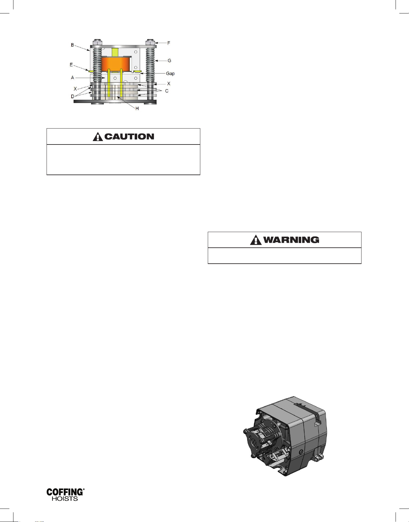
2. Refer to Figure 5. Open disc brake manually by using two
screwdriver blades, one on each side of the brake at a
point close to the brake spring posts. Apply pressure to the
underside of the armature plate (points “X”) to close the
solenoid and release the brake.
3. Use several quick releases instead of holding brake open
continuously. Do not exceed normal lowering speed.
Do not allow screwdriver blades to touch rotating friction
disc “C”.
To avoid personal injury:
Do not use the equipment shown in this manual to lift, support, or
otherwise transport people, or to suspend loads over people.
8. Don’t lower into areas where visibility is obscured unless
someone else is guiding the operation.
9. Use common sense at all times when operating a hoist.
10. Do not operate if direction of hook travel is not the same as
indicated on button being pushed.
11. Do not operate unless hook travel limit devices function. Test
without load each shift.
12. Do not operate when hoist is not centered over load.
13. Do not operate if chain is not seated properly in sprockets or
sheave grooves.
14. Do not operate damaged or malfunctioning hoist.
4-2. OVERLOAD LIMITING PROTECTION
This hoist is equipped with a factory-calibrated overload limiting
clutch that will permit the lifting of loads within its rated capacity,
but will prevent the lifting of damaging overloads while the hoist is
being operated. If the load being lifted exceeds the lifting capability
of the overload clutch, the hoist motor will continue to run, causing
overheating of both the clutch and hoist motor. This condition should
be avoided by immediately releasing the “UP” button and reducing
the load to within the rated capacity of the hoist. See GEARING,
page 10, for additional instructions on this device.
The overload limiting clutch is an emergency protective device and
should not be used to measure the maximum load to be lifted, or to
sense the overload imposed by a constrained load. While the overload
limiting clutch will protect the hoist from damaging overloads, it will not
ensure that a load is within the rated capacity of the hoist.
Do not allow the load to descend rapidly. This causes the motor
to race and serious damage may result.
5-3. HOOKS
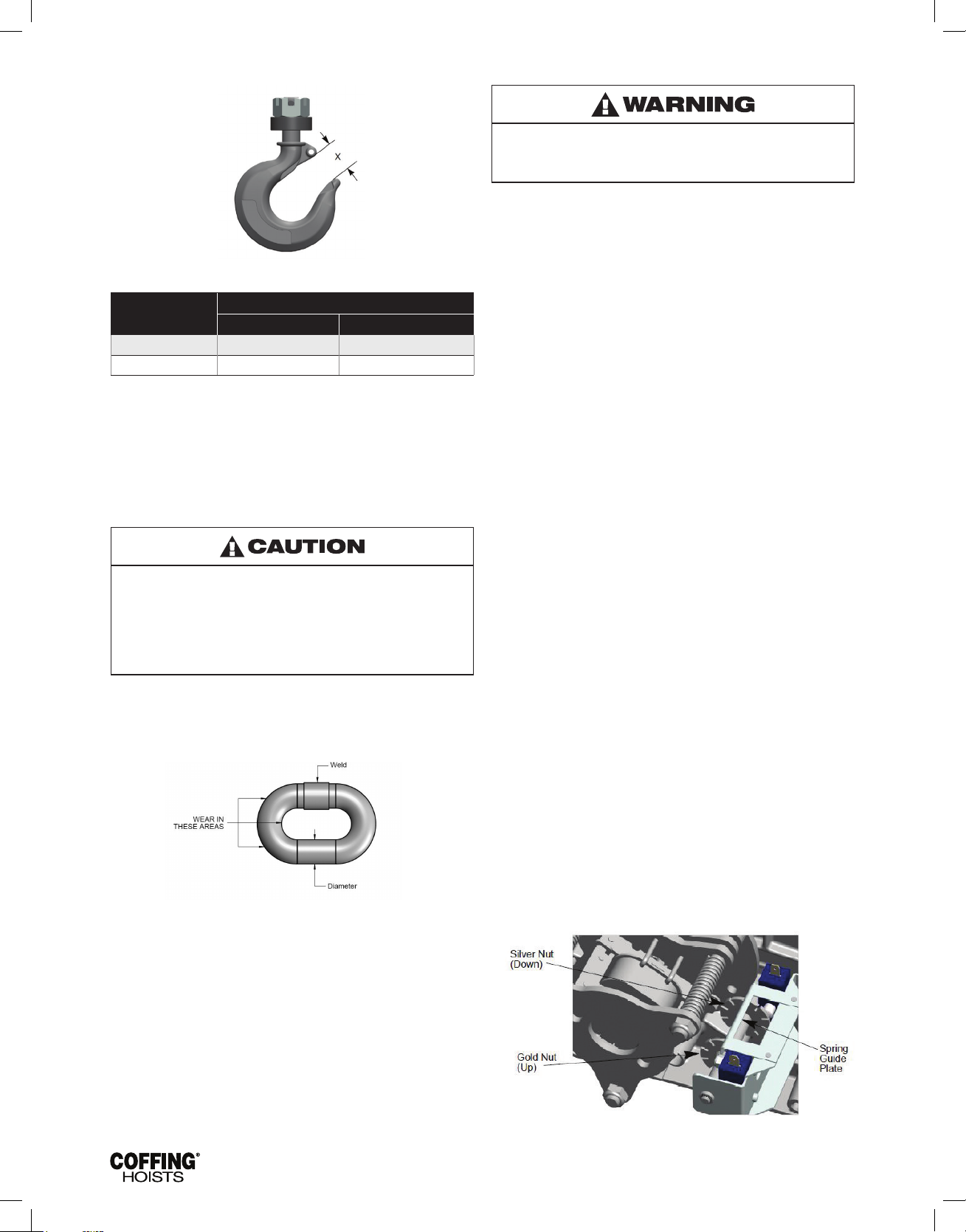
Refer to Figure 2.
1. Inspect hooks once daily for cracking, extreme wear or
spreading. Replace hooks showing any of these signs. If
the throat openings are spread wider than the maximum
permissible 15% increase listed here, the hooks have been
overstressed and must be replaced. Any hook that is bent or
twisted more than 10 degrees from the plane of an unbent hook
must also be replaced.
2. The hook latches should be inspected to ensure that they
close the hook throat opening in a secure manner when a load
is applied. Inspect the hook shank and nut for any stripping
of the threads or other damage. The hook nut should be fully
restrained by the retaining pin.
3. In addition to above, load hooks should be inspected for cracks
by the magnetic particle, dye penetrant or other suitable crack
testing inspection method. This should be done at least once
a year.
7
Page 10
JLC680-2 Rev AA April 2019
Figure 2 — Hook Inspection
Hoist Capacity
Top Hook Bottom Hook
"X" Dimension
1 Ton & Under 1-11/32” 1-7/32”
2 Ton 1-11/32” 1-11/32”
(*) Maximum permissible throat opening of hook.
5-4. CHAIN
Chain inspection and lubrication are the most important aspects of
hoist maintenance. Chain is to be kept clean and lubricated (See
LUBRICATION, page 9) at all times. Visually check the chain every
time the hoist is used. Hoist must not be operated when the chain is
twisted or kinked. Chain inspection will not usually require removal
of the chain from the hoist, but the chain should be run through the
hoist enough so that every link is made visible for inspection.
Load chain that is kept clean and lubricated is essential to the
safe operation of a hoist. Failure to do so may cause serious
hoist damage, spillage of chain from chain container (when
equipped). cross-linked chain resulting in dropped loads
and other hazardous conditions that may result in injury or
death. Chain contaminated with foreign substance must be
removed from service, cleaned and lubricated before hoist
use can continue.
a. Check each link for gouges, nicks, weld splatter, corrosion,
and distortion.
b. Inspect each link for wear to the diameter of the link. The
nominal link diameter is 0.281 inch. If the diameter of any
link of 0.281 chain is worn to less than 0.225 inch, the entire
chain must be replaced.
c. 1. Check the chain for overall wear or stretch by selecting
an unworn, unstretched length of chain (at the slack end,
for example). Let the chain hang vertically with a light load
(about 20 pounds) on the chain to pull it taut. Use a large
caliper to measure the outside length of a convenient
number of links (about 12 inches). Measure the same
number of links in a used section of chain and calculate the
percentage increase in length of the worn chain.
2. If the length of the worn chain is more than 1-1/2%
longer than the unused chain (0.015 inch per inch of chain
measured), then the chain should be replaced. If the chain
is worn less than 1-1/2%, check it at several more places
along its length. If any section is worn more than 1-1/2%,
the chain should be replaced
d. The chain used in the hoist is accurately calibrated to
operate over the load sprocket and is very carefully heat
treated for maximum wear life and strength.
Do not weld or join hoist load chain.
Do not substitute another manufacturer's chain in this hoist.
Damage or wear, beyond the stated limits, to any portion of
the chain requires that the entire length of chain be replaced.
CHAIN REPLACEMENT WITH CHAIN IN HOIST
Refer to Figures 3 & 4.
1. Run hook up to its top limit.
2. DISCONNECT HOIST FROM POWER SUPPLY and remove the
electrical cover.
3. Using a screwdriver, pry the spring guide plate out of the slots
in the limit switch nuts (See Figure 3). Turn the gold nut back to
about the center of the threaded screw. Do not disconnect the
wires from the limit switches.
4. Remove the load block assembly from the old chain. On
double-chained hoists detach the chain from the chain support
and pull it through the load block assembly (See Figure 4).
5. Make a “C” shaped chain link by grinding through the end link
on the load end of the old chain.
6. Using the “C” link, attach the new chain to the load end of the
old chain. Be sure that the welds of the upstanding links of the
new chain will face outward from the load sheave. The end links
must be oriented for attachment to the dead-end attachment
pin and the chain support (double-chained only) without any
twist in the chain. (See Figure 23)
7. With the electrical cover off, connect the hoist to the power
supply. Be sure that the green ground wire is properly grounded
(See INSTALLATION 3b, page 4).
8. Carefully jog the “UP” button and run the joined pieces of chain
into the hoist until about 15" of the new chain comes out the
other side.
9. DISCONNECT HOIST FROM POWER SUPPLY.
10. Remove the “C” link and the old chain. Remove the chain
stop by prying off its retaining ring with a athead screwdriver.
If attached, remove the old chain from the chain stripper by
removing the retainer clip and attachment pin.
11. Attach the chain stop to the slack end of the new chain by
capturing the 12th link with the two stop halves positioned with
their tapered ends pointing towards the hoist. Slide the sleeve
over the halves and attach the retaining ring. If you are not
using a chain container, attach the slack end of the new chain
to the side of the hoist using the attachment pin and retainer
clip. DO NOT allow twists in the chain.
12. Adjust the lower limit switch (See ADJUSTING LOWER LIMIT,
page 8).
13. Attach the bottom block on single-chained hoists using a
new load block pin (See Figure 23). On double-chained hoists,
feed the chain through the load block (welds of the upstanding
links will be in towards the sheave) and fasten the end of the
chain to the chain support using a new chain support pin
(See Figure 23). Be sure there are no twists in the chain.
14. Adjust the upper limit switch (See ADJUSTING UPPER LIMIT,
page 8).
Figure 3 — Limit Switch Assembly
8
Page 11
JLC680-2 Rev AA April 2019
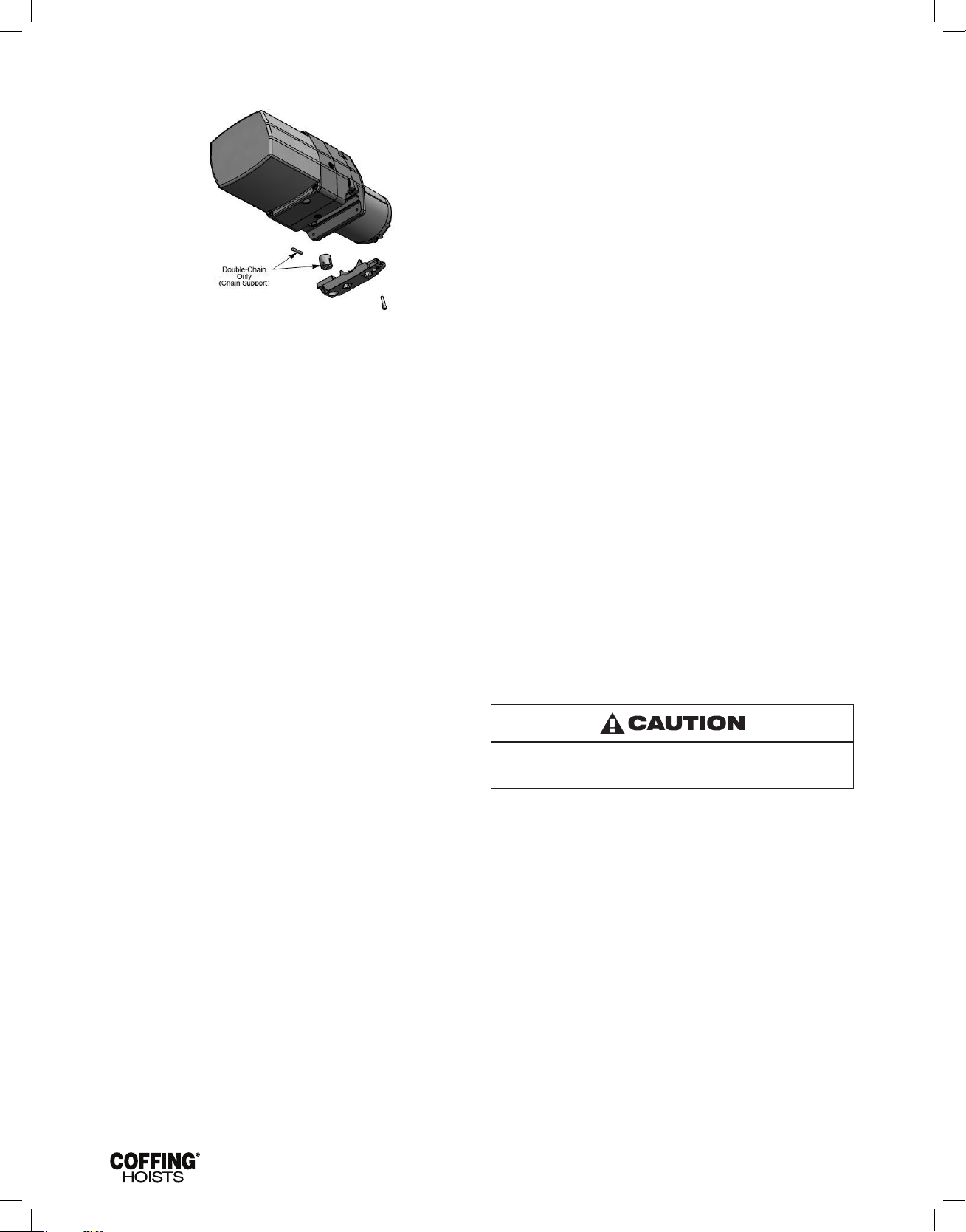
Figure 4 — Chain Replacement Diagram
CHAIN REPLACEMENT WITH NO CHAIN IN HOIST
Refer to Figure 4.
1. DISCONNECT HOIST FROM POWER SUPPLY and move hoist
to a work table. Remove the electrical cover, electrical panel
and the electric brake assembly.
2. Detach the chain stripper from the bottom of the hoist.
3. Insert the new chain between the load sheave and the chain
guide. Feed the chain into the hoist by manually turning the
brake hub adaptor. Allow about 15" of chain below the hoist
on the slack end. Be sure the welds of the upstanding links are
out away from the load sheave and that proper orientation is
observed for attachment of the slack end. Also be sure the load
hook assembly (if already attached to the chain) is toward the
center of the hoist or to your right looking from the motor end.
4. Reinstall the chain stripper (with the chain support on doublechained hoists, See Figure 4) observing proper chain alignment
and avoiding any twist in the chain.
5. Follow steps 11 through 14 in previous section, CHAIN
REPLACEMENT WITH CHAIN IN HOIST, to complete the chain
replacement procedure.
NOTE: Inspect chain guides and load sheave for wear, replace as
needed.
“clicks” then turn two slots farther. Release the spring guide
plate and be sure it slips back into the slots in both limit
switch nuts. Do not disturb the silver slotted nut if it has
been set previously.
ADJUSTING LOWER LIMIT (SILVER NUT)
Refer to Figure 3.
1. Suspend the hoist. Carefully lower the load block to a point
where the slack-end loop of the chain hangs down 6" or more
from the hoist housing (or the limit desired in any particular
application allowing the minimum 6"). There should be a
minimum clearance of 1-1⁄2" between the chain stop and
bottom of hoist.
2. DISCONNECT HOIST FROM POWER SUPPLY and remove the
electrical cover.
3. With a screwdriver, pry the spring guide plate out of the slots in
the limit switch nuts.
4. Turn the slotted silver nut toward its limit switch until the switch
“clicks,” then turn two slots farther. Release the spring guide
plate and be sure it slips back in the slots in both limit
switch nuts. Do not disturb the gold slotted nut if it has
been set previously.
CHECK BOTH UPPER AND LOWER LIMITS
1. Connect the hoist to the power supply. Be sure the green
ground wire is properly grounded (See Installation 3-b, page 5).
2. Check load hook direction (See Installation 3-c, page 5).
3. Carefully raise load block to upper limit and observe if it stops
automatically at desired level. Do not allow load block to run
into hoist housing — this will damage the hoist. Maintain a
minimum clearance of 2" from the hoist housing and the top
of the load block on single-chained models and 1" from the
chain support to the top of the load block on double-chained
models.
4. Carefully lower load block to lower limit and observe if it stops
automatically at the desired level. Do not allow slack-end loop
of chain to become taut against hoist housing. This will damage
the hoist. There should be a minimum clearance of 11⁄2"
between the chain stop and the bottom of the hoist.
5. If upper and lower limits operate satisfactorily, hoist is ready for
use. If they are not as desired, repeat adjustment.
5-5 LIMIT SWITCH ADJUSTMENT
IMPORTANT: Before placing hoist in operation, check the limit
switch adjustment. Limit switches are provided to protect the hoist
against damage resulting from overtravel or to allow setting the hook
travel within the factory-set limits of travel. The standard limit switch
is designed for lifts of 50 ft or less on single-chained hoists and 25 ft
or less on the 2 ton, double-chained models. The long lift limit switch
allows for the maximum amount of lift, which is 143 ft on the 1 ton
and under models, and 71 ft on the 2 ton models.
The upper and lower limit switch adjusting nuts are color-coded
gold and silver respectively. Each limit nut has 10 slots for ne
adjustment, and the increment of adjustment is such that one slot is
equivalent to approximately one link of chain travel with the standard
limit switch. Movement of the limit switch nuts toward or away from
each other decreases or increases the hook travel respectively.
ADJUSTING UPPER LIMIT (GOLD NUT)
Refer to Figure 3.
1. Suspend the hoist. For single chain models raise the load
block until there is a minimum clearance of 2" from the hoist
housing and the top of the block. Double chain models require
a minimum clearance of 1" from the chain support to the top of
the load block.
2. DISCONNECT HOIST FROM POWER SUPPLY and remove the
electrical cover.
3. With a screwdriver, pry the spring guide plate out of the slots in
the limit switch nuts.
4. Turn the slotted gold nut toward its limit switch until the switch
If the wires running to the limit switches are ever disconnected
for any purpose, be sure to replace wires in accordance with the
correct wiring diagram (See Figures 9A, 9B, 9C & 9D).
5-6 BRAKE
Properly adjusted, this brake will release promptly when energized.
It is capable of both smoothly stopping and securely holding the
rated capacity of the hoist. If the hoist develops either undesirable
over-travel after the pushbutton is released (this condition is most
noticeable in the lowering direction) or hesitates to lift the load
promptly when the pushbutton is depressed (this condition is most
noticeable in the hoisting direction), the brake should be adjusted.
BRAKE ADJUSTMENT
Refer to Figure 5.
1. DISCONNECT HOIST FROM POWER SUPPLY and remove the
electrical cover.
2. With reference to Figure 5, the gap between the brake
armature “A” and the eld “B” should be checked. The
correct gap is 0.015". Adjustment should not be necessary
until gap reaches 0.040".
3. Adjust the gap using a 9/16" wrench on the 3 locknuts “F”.
Check with a feeler gauge to be sure the gap is the same on
both ends of the solenoid.
4. Adjustment is now complete and the brake properly set.
Replace the electrical cover, reconnect the power supply,
and check hoist brake action.
9
Page 12
JLC680-2 Rev AA April 2019
Figure 5 — Brake Assembly
Be sure the bottom of the armature "A "does not bear against
the splined adapter “H”. As adjustments are made, the builtin clearance will be reduced. When this clearance is gone
REPLACE BRAKE DISCS. Minimum allowable disc thickness is
.162".
5-7 HOIST CONTROLS
Both the pushbutton and the reversing contactor are mechanically
interlocked to prevent shorting the circuit and causing serious
damage. As part of maintenance, always check for proper closure
of contact points as well as for burned contacts. If replacement is
necessary, see Figures 16, 17, 18, and 19 for replacement parts.
5-8 WIRING
Refer to Figures 9A, 9B, 9C & 9D.
Single-phase units (115/230V) are shipped wired for 115V and
the 1-speed, 230/460V-3 phase units are wired for 460V unless
otherwise specied when ordered. Hoists wired for other voltages
and 2-speed units are single voltage only. Conversion of dualvoltage hoists to either the higher or lower voltage can be done
simply and quickly as follows:
1. DISCONNECT HOIST FROM POWER SUPPLY and remove the
electrical cover.
2. Each dual-voltage hoist has a terminal block assembly for the
interconnection of the electrical components of the hoist. To
convert the voltage, reconnect the leads to the terminal blocks
according to the wiring diagram located inside the electrical
cover or Figures 9A, 9B, 9C and 9D.
DO NOT move any wires or make any changes to the
electrical circuit except at the terminal block assembly.
Tug on wires to ensure they are securely connected.
3. After converting the voltage, recheck phasing and limit switch
operation (See INSTALLATION 3-c & 5, page 5).
IMPORTANT: Always refer to the wiring diagram located on the
inside of the electrical cover or Figures 9A, 9B, 9C and 9D when
performing electrical repairs. Make sure all connections are secure
and check for damaged insulation. It is also imperative that the
power circuit has conductors of adequate size (See Table 5).
5-9 LUBRICATION
Refer to Figure 11.
Proper lubrication is necessary for a long and relatively trouble-free
hoist operation. Refer to the following and the RECOMMENDED
LUBRICATION SCHEDULE for lubrication points, type of lubricant,
and frequency of lubrication.
oil level ll plug from the side of the hoist. With the hoist hanging
level, gear oil should be even with the hole. Change oil periodically
depending on the severity of the application and the environmental
conditions (at least every 200 hours of run time).
BEARINGS
All bearings except hook and idler sheave bearings are lubricated
at the factory and should not require additional lubrication. Noisy or
worn bearings should be replaced.
LIMIT SWITCH SHAFT
Remove any dirt accumulation and spray with a general purpose
lubricant.
HOOK BEARING
Apply a few drops of SAE 30 Wt. gear or motor oil around the edge
of the bearing.
IDLER SHEAVE BEARING (BUSHING)
Disassemble load block and apply a light coat of NLGI #2 grease, or
equivalent, inside of bearing.
5-10 HOIST REPAIRS
1. For major repairs or when the hoist is to be sectioned in the
suspension area, it will be necessary to move the hoist to a
workbench or table.
2. For repairs which can be done by removing the electrical cover
only, the hoist need not be moved. Lowering the hoist to a
convenient working level is desirable.
NOTE: If you do not have an experienced mechanic to do your
repair work, we recommend that you send your hoist to an approved
service station for repairs. Use authorized repair parts only.
Remove load and disconnect hoist from power supply before
starting to do any repairs or to take any sections apart.
The following repair instructions will help you in understanding repair
procedures, when related to the Replacement Parts List starting on
page 21. For clarity these are broken down into areas.
ELECTRICAL PARTS AND BRAKE
1. Refer to Figures 15, 16 and 17. Remove the cover to access
the controls. Single-phase models also have a starting switch
and capacitor mounted on the panel as shown in Figure 16.
The terminal blocks and end clamps snap off of the rails on the
panel plate using a small screwdriver. DO NOT SLIDE THE END
CLAMPS. The reversing contactor can be slid off the rail, but it
must be snapped on. Where the contactor ts the rail, one side
has springs or pads that apply pressure against the edge of the
rail. By pressing against that side at the base of the contactor,
you can snap the part on or off using a rotating action. Note the
numbers that label the terminals on the contactor and orient the
part as shown in Figures 9A-9D. Single-phase contactors have
a small jumper that is not present on the 3-phase (note the 3
and 5 terminals on the reversing contactor in Figure 9A).
2. Remove the electrical panel by removing the stand-off screws
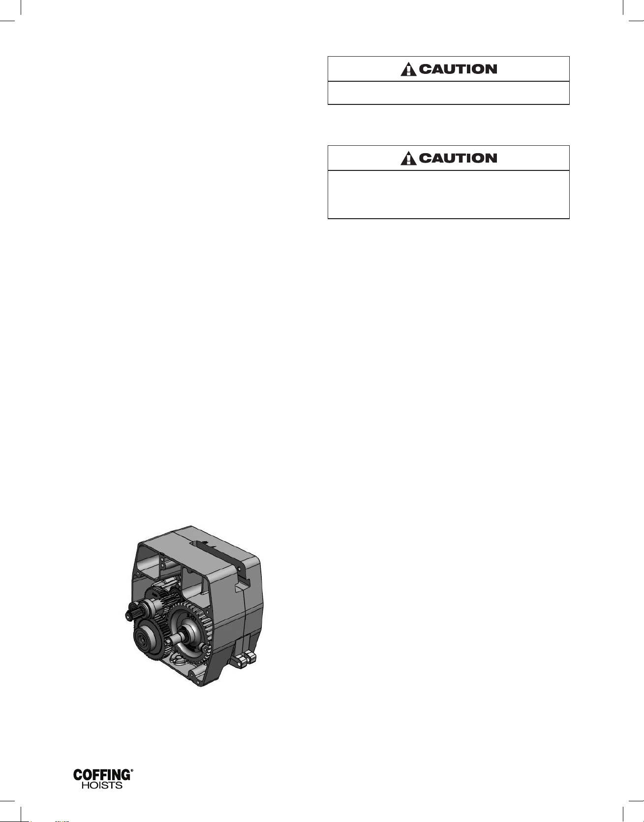
(See Figures 16 & 17). The limit switch and brake are now
accessible as shown in Figure 6.
LOAD CHAIN
Clean the load chain with acid-free solvent and coat with SAE 90 Wt.
gear oil. Wipe excess oil to prevent dripping. Never apply grease to
the chain.
GEARING
The gear case of this hoist is lled at assembly with approximately
2 pints of SAE 90 Wt. EP gear oil. Check oil level by removing the
10
Figure 6 — Electrical Panel Removed
Page 13
JLC680-2 Rev AA April 2019
3. Remove the transformer bolted to the back of the panel plate if
it requires replacement.
4. Refer to Figure 15 to disassemble the brake. See BRAKE
ADJUSTMENT on page 9 to properly set the brake.
5. Refer to Figures 20 and 21 to disassemble the limit switch. See
LIMIT SWITCH ADJUSTMENT on page 8 to properly set the
upper and lower limits of travel.
6. Refer to Figures 18 and 19 for repairs on the pushbutton
station. Also refer to the wiring diagram inside the electrical
cover or Figures 9A, 9B, 9C and 9D for wiring instructions.
There are wires running through the hoist. Carefully ease the
hoist sections apart. Do not jerk them apart.
7. Inspect gears for broken or severely worn teeth and inspect
all bearings. Replace as necessary. The overload slip clutch is
factory calibrated and must not be disassembled or readjusted.
MOTOR
Refer to Figures 12, 13 and 14.
The hoist motor is located on the opposite end to from the electrical
parts, but the two are tied together with electrical leads running
through the housing.
1. If it is necessary to replace or repair the motor, DISCONNECT
THE HOIST FROM THE POWER SUPPLY and remove the
electrical cover.
2. Loosen the screw clamps on the terminal blocks and reversing
contactor to disconnect the motor leads (See Figures 16 and
17).
3. Remove the four motor mounting bolts attaching the motor to
the housing. It will come loose at the motor coupling.
4. Inspect the motor coupling, motor shaft and all the bearings.
Replace as necessary.
5. Install new or repaired motor according to the wiring diagram
located inside the electrical cover or Figures 9A, 9B, 9C and
9D.
GEARING
Refer to Figures 7, 12 and 22.
As disassembly is extensive for gearing, disconnect the hoist and
move it to a workbench.
1. Remove the electrical cover.
2. Remove the electrical panel.
3. Remove the brake assembly and the limit switch assembly.
4. Remove the limit switch spring from output shaft bore.
5. Drain the oil from the transmission.
6. Remove the ve screws that attach the transmission cover to
the transmission housing and remove the transmission cover.
Figure 7 — Assembled Gearing
Do not disassemble or readjust the clutch, or replace it with
a clutch assembly from another hoist. Doing so will void the
warranty and may create an unsafe condition. If replacement
is needed due to wear or loss of adjustment, always use a new
clutch assembly.
8. Reassemble in reverse order of disassembly, making sure that
the gasket is in place and in good condition. Coat gasket with
Permatex
®
or other gasket cement. Extreme care should be
taken to avoid damage to oil seals.
9. Check all wire terminals to be sure that they are properly seated
and in accordance with the correct wiring diagram. Before
placing the hoist back into service, check the brake adjustment
and limit switch settings.
CHAIN GUIDE AND LOAD SHEAVE
(Refer to Figures 12, 22 & 23)
The hoist sections must be separated at the top hook line in order
to inspect the Load Sheave and Chain Guide.
1. Disconnect the Hoist and remove to a workbench.
2. Remove the Socket Head Cap Screw and Attachment Pin
that hold in the Chain Stripper.
3. Remove the Chain Stripper.
4. Remove the 4 bolts that hold on the Motor.
5. Remove the Motor.
6. Remove the Spring Washer and Motor Coupling.
7. Remove the Hook Retaining Screw.
8. Remove the Hook Retainer.
9. Remove the Top Hook (Note the orientation of the hook for
reassembly).
10. Remove the remaining 3 Screws that hold on the Trim Cover.
11. Remove the Trim Cover.
12. Remove the 5 Socket Head Cap Screws that hold the Sheave
Housing to the Transmission Housing.
13. Gently pry apart the two housings using the slots provided,
taking care not to damage the Gasket between the two
housings.
While these housings are apart, check the following:
• Chain Stripper
• Chain Guide
• Chain
• Load Sheave
• Load Sheave Shaft
• Bearings
• Chain Support (on 2 ton models)
Replace worn or damaged parts as necessary including screws, lock
washers, pins, etc. Care must be taken during reassembly to have
the hook in the proper orientation (See SUSPENSION, page 11).
SUSPENSION
Periodic inspections of the top suspensions can be made without
disassembly. For more extensive inspections the lug or top hook
11
Page 14
JLC680-2 Rev AA April 2019
may be removed as follows:
1. Disconnect the Hoist and remove it to a workbench.
2. Remove the Hook Retaining Screw.
3. Remove the Hook Retainer.
4. Remove the Hook (Note the orientation of the hook for
reassembly).
Care must be taken during reassembly to have the hook in proper
orientation. Refer to gures 8A, 8B & 8C for proper orientation
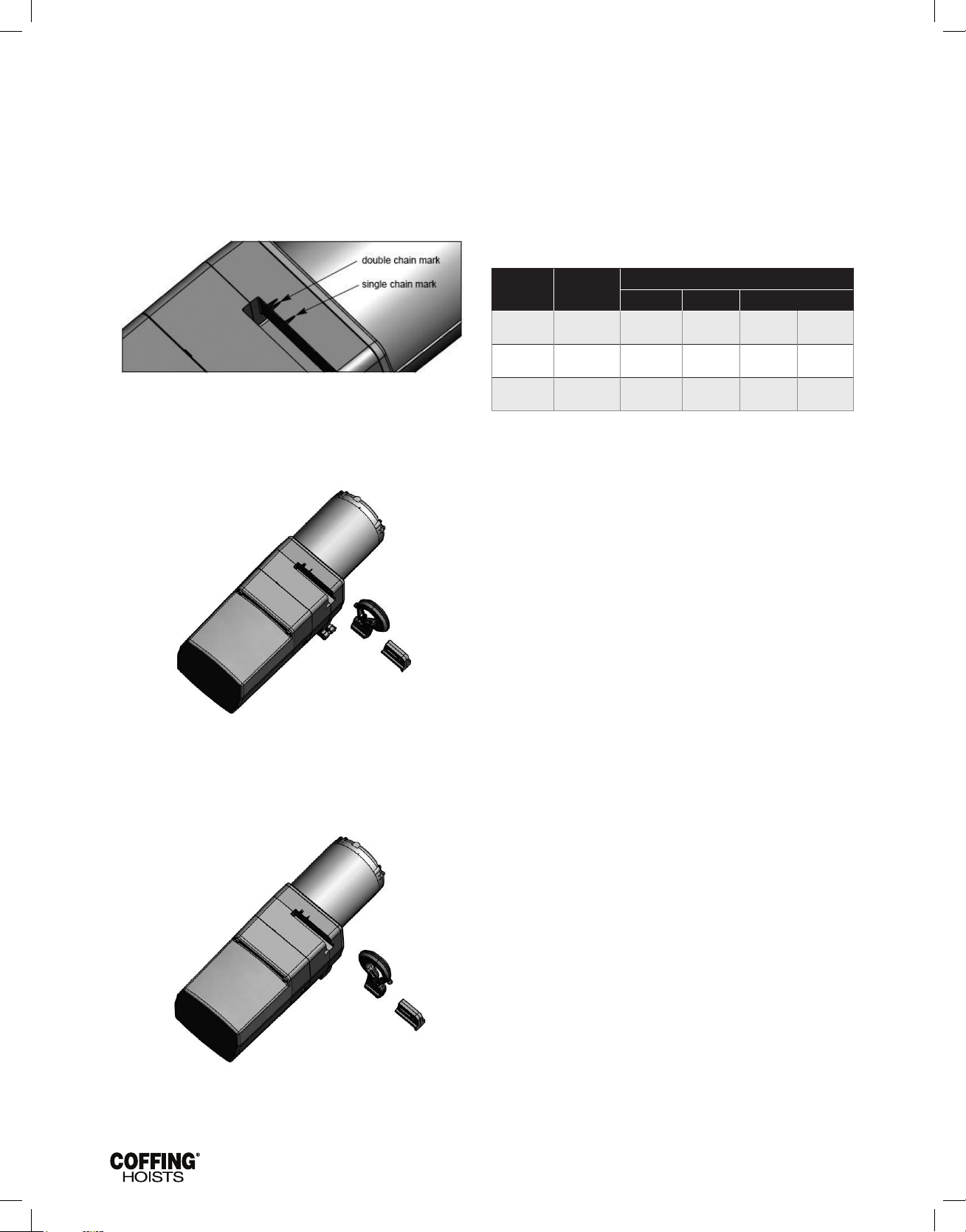
Figure 8A — Hook Orientation Marks
For Single Chain Hoist Installation, orient the centerline of the top
hook with the single mark on the top of the sheave housing (Figure
8A). Hook installation should be as shown in Figure 8B.
5-11 POWER CORD PRECAUTIONS WITH
1-PHASE HOISTS
Electric hoists require a sufcient power supply. It is especially
important with single-phase voltage to ensure that the conductors
running to the hoist from the power source are adequate in
size to handle the power requirements of the hoist. Inadequate
power cables and branch circuits will cause low voltage, high
amperage, damage to the hoist, and potential fire hazards.
Such problems can be minimized by using 230V power on 115/230V
hoists. The following are recommendations for the conductor gage
size depending on the length, horsepower, and voltage.
Table 5 - Recommended Conductor Sizes for 1-Phase Hoist
Hoist HP
(fast/slow)
1/4
1/2
1
Voltage
(1-Phase)
115V
230V
115V
230V
115V
230V
Maximum Length of Power Cord in Feet
14 AWG 12 AWG 10 AWG 8 AWG
75
350
40
200
0
120
120
560
60
330
30
190
190
900
100
250
50
310
300
–
150
810
75
490
Figure 8B - Single Chain Hook Orientation
For Double Chain Hoist Installations, orient the centerline of the
top hook with the double marks on the top of the sheave housing
(Figure 8A). Hook installation should be as shown in Figure 8C.
Figure 8C - Double Chain Hook Orientation
When reassembled, recheck the limit switch settings
(See LIMIT SWITCH ADJUSTMENT, page 8).
12
Page 15
JLC680-2 Rev AA April 2019
VI — TROUBLESHOOTING
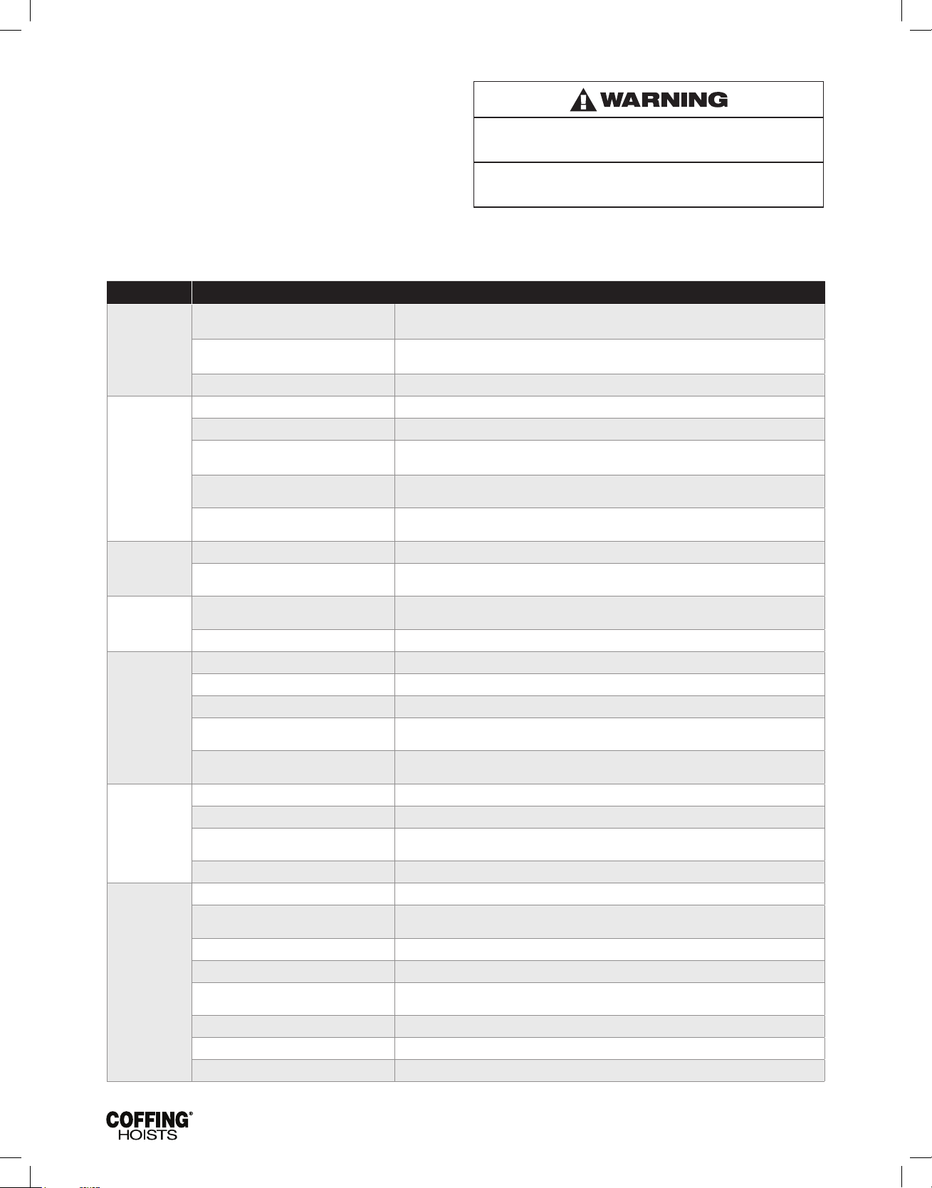
Always disconnect unit from the power supply system before
removing hoist covers or the back cover of control station
Problem Probable Cause Remedy
1. Check adjustment (See LIMIT SWITCH ADJUSTMENT, page 8). Check connections against
wiring diagram. Tighten loose connections or replace.
2. Check for stripped threads or bent nut guide.
3. Check all connections at line connectors and on terminal block. Check terminal block on dual
voltage hoists for proper voltage connections.
4. Check connections to the solenoid coil. Check for open or short circuit. Check for proper
adjustment (See BRAKE ADJUSTMENT, page 9).
5. Check coils for open or short circuit. Check all connections in control circuit. Check for burned
contacts. Replace as needed.
2. Check brake adjustment (See BRAKE ADJUSTMENT, page 9). It may be necessary to replace
discs.
1. Reverse any two wires (except the green ground wire) at the power source (See INSTALLATION
3c, page 5).
4. Determine cause of low voltage and bring up to within plus or minus 10% of the voltage
specified on the motor. Measure voltage at the hoist reversing contactor while lifting a load.
5. Replace faulty component
3. Check coils for open or short circuit. Check all connections in control circuit. Check for burned
contacts. Replace as needed.
2. Determine cause of low voltage and bring up to within plus or minus 10% of the voltage
specified on the motor. Measure voltage at the hoist reversing contactor while lifting a load.
5. Check coils for open or short circuit, check all connections in control circuit. Check for burned
contacts. Replace as needed.
Hook fails to stop
at end of travel
Hoist does not
respond to
pushbutton
Hook does not
stop promptly
Hook moves in
wrong direction
Hoist hesitates
to lift when
energized
Hook raises but
will not lower
Hook lowers but
will not raise
1. Limit switch not operating.
2. Brass limit switch nuts not moving on
shaft.
3. Hoist reversing contactor malfunctioning. 3. Remove electrical cover and check reversing contactor.
1. Power failure in supply lines. 1. Check circuit breakers, switches and connections in power supply lines.
2. Wrong voltage or frequency. 2. Check voltage and frequency of power supply against the rating on the nameplate of the motor.
3. Improper connections in hoist or
pushbutton station.
4. Brake does not release.
5. Faulty hoist reversing contactor
1. Hoist overloaded. 1. Reduce load to within rated capacity of hoist.
2. Brake not holding.
1. Three phase reversal.
2. Improper connections. 2. Check all connections against wiring diagram.
1. Hoist overloaded. 1. Reduce load within rated capacity of hoist.
2. Motor brake requires adjustment. 2. Check motor brake adjustment (See BRAKE ADJUSTMENT, page 9)
3. Worn overload limiting clutch. 3. Replace clutch.
4. Low voltage.
5. Faulty SINPAC
capacitor (single phase hoist only).
1. “DOWN” circuit open. 1. Check circuit for loose connections. Check “DOWN” limit switch for malfunction.
2. Broken conductor in pushbutton cable. 2. Check each conductor in the cable. If one is broken, replace entire cable.
3. Faulty hoist reversing contactor.
4. Loose screw clamps. 4. Ensure that screw clamps are tightened on the terminal blocks and reversing contactor.
1. Hoist overloaded. 1. Reduce load to within rated capacity of hoist.
2. Low voltage.
3. “UP” circuit open. 3. Check circuit for loose connections. Check “UP” limit switch for malfunction.
4. Broken conductor in pushbutton cable. 4. Check each conductor in the cable. If one is broken, replace entire cable.
5. Faulty hoist reversing contactor.
6. Faulty capacitor (single phase hoist only). 6. Check starting capacitor on motor. Replace if necessary.
7. Worn overload limiting clutch. 7. Replace overload clutch assembly.
8. Loose screw clamps. 8. Ensure that screw clamps are tightened on the terminal blocks and reversing contactor.
®
starting switch or start
Failure to follow proper lockout/tagout procedures may
present the danger of electrical shock.
TO AVOID INJURY:
Disconnect power and lockout/tagout disconnecting means
before removing cover or servicing this equipment
13
Page 16
JLC680-2 Rev AA April 2019
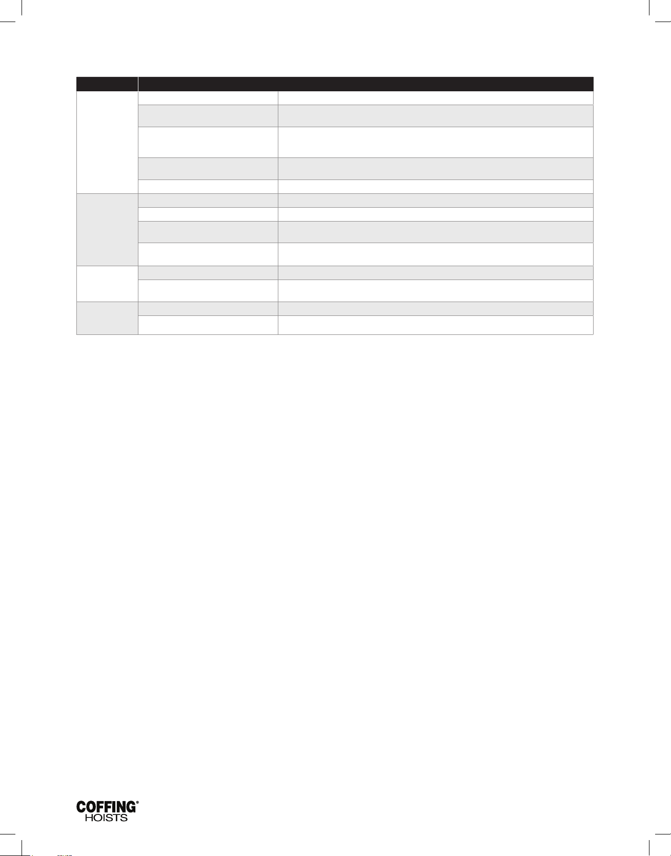
SECTION VI — TROUBLESHOOTING CONTINUED
Problem Probable Cause Remedy
1. Excessive load. 1. Reduce load to within rated capacity of hoist.
2. Determine cause of low voltage and bring up to within plus or minus 10% of the voltage
specified on the motor. Measure voltage at the hoist reversing contactor while lifting a load.
3. As the ambient temperature rises towards the 130°F limitation of the unit, frequency of the hoist
operation must be limited to avoid overheating of the motor. See ADVERSE ENVIRONMENTAL
CONDITIONS, page 4.
4. Excessive inching, jogging or reversing should be avoided since this type of operation will
drastically shorten the life of motor, contactor and brake.
3. Ensure that the voltage at the reversing contactor is within ±10% of the nominal voltage while
lifting a load.
4. Replace overload clutch assembly.
2. Ensure that the voltage at the reversing contactor is within ±10% of the nominal voltage while
lifting a load.
Motor
overheats
Lack of proper
lifting speeds
Motor brake noise
or chatter (while
starting hoist)
Motor brake “buzz”
(anytime hoist is
running)
2. Low voltage.
3. Extreme external heating.
4. Frequent starting or reversing.
5. Brake dragging. 5. Check brake adjustment (See BRAKE ADJUSTMENT, page 9)
1. Hoist overloaded. 1. Reduce load to within rated capacity of hoist.
2. Brake dragging. 2. Check for proper brake adjustment or other defects.
3. Low voltage.
4. Overload limiting clutch intermittently
slipping.
1. Brake needs adjustment. 1. See BRAKE ADJUSTMENT, page 9.
2. Low voltage
1. Brake needs adjustment. 1. See BRAKE ADJUSTMENT, page 9.
2. Broken shading coil on brake frame. 2 . Replace shading coil or complete brake frame assembly.
14
Page 17
JLC680-2 Rev AA April 2019
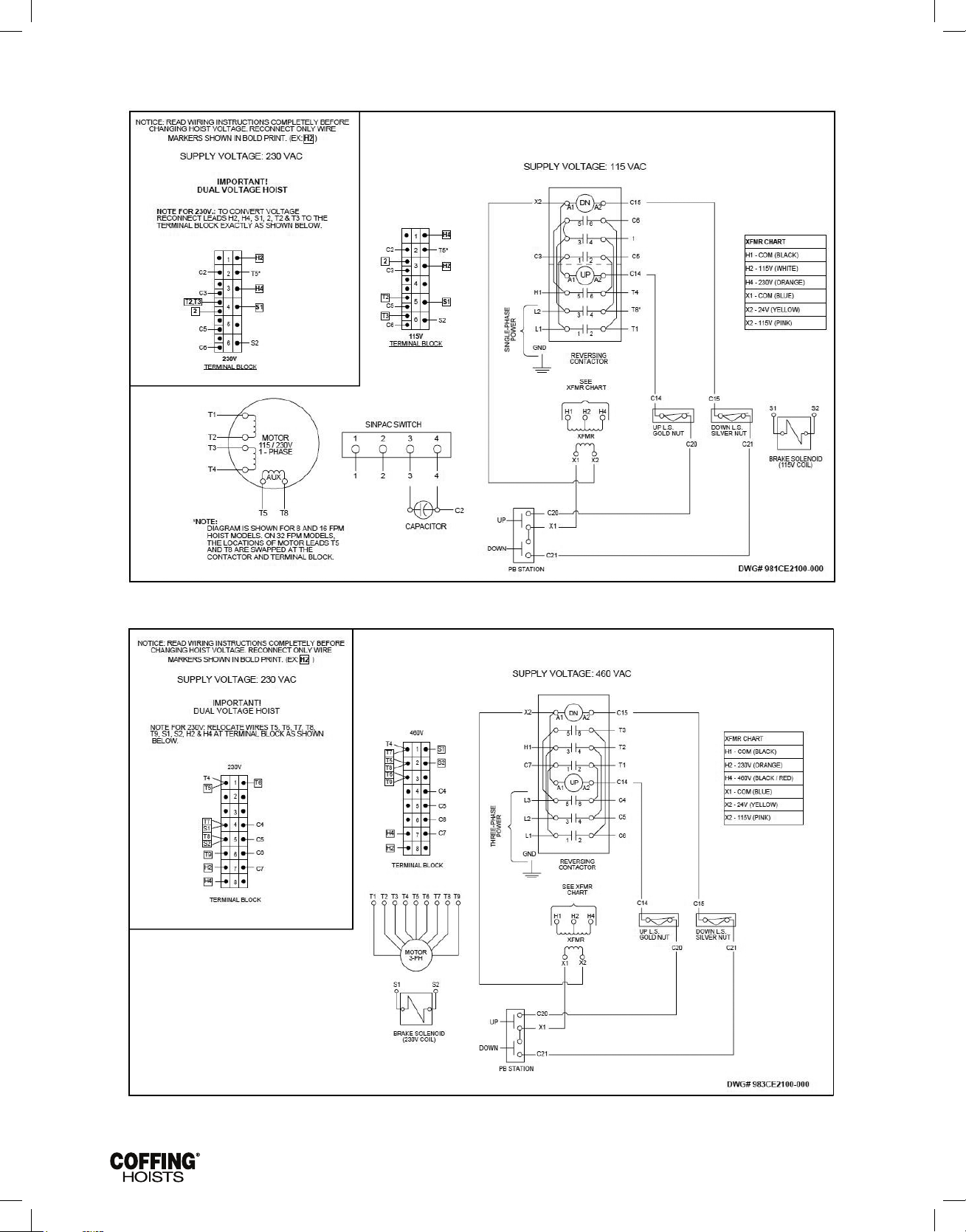
SECTION VII — WIRING
Figure 9A — Wiring Diagram for 115/230V - 1 Phase Models
Figure 9B — Wiring Diagram for 1-Speed, 230/460V - 3 Phase Models
15
Page 18
JLC680-2 Rev AA April 2019
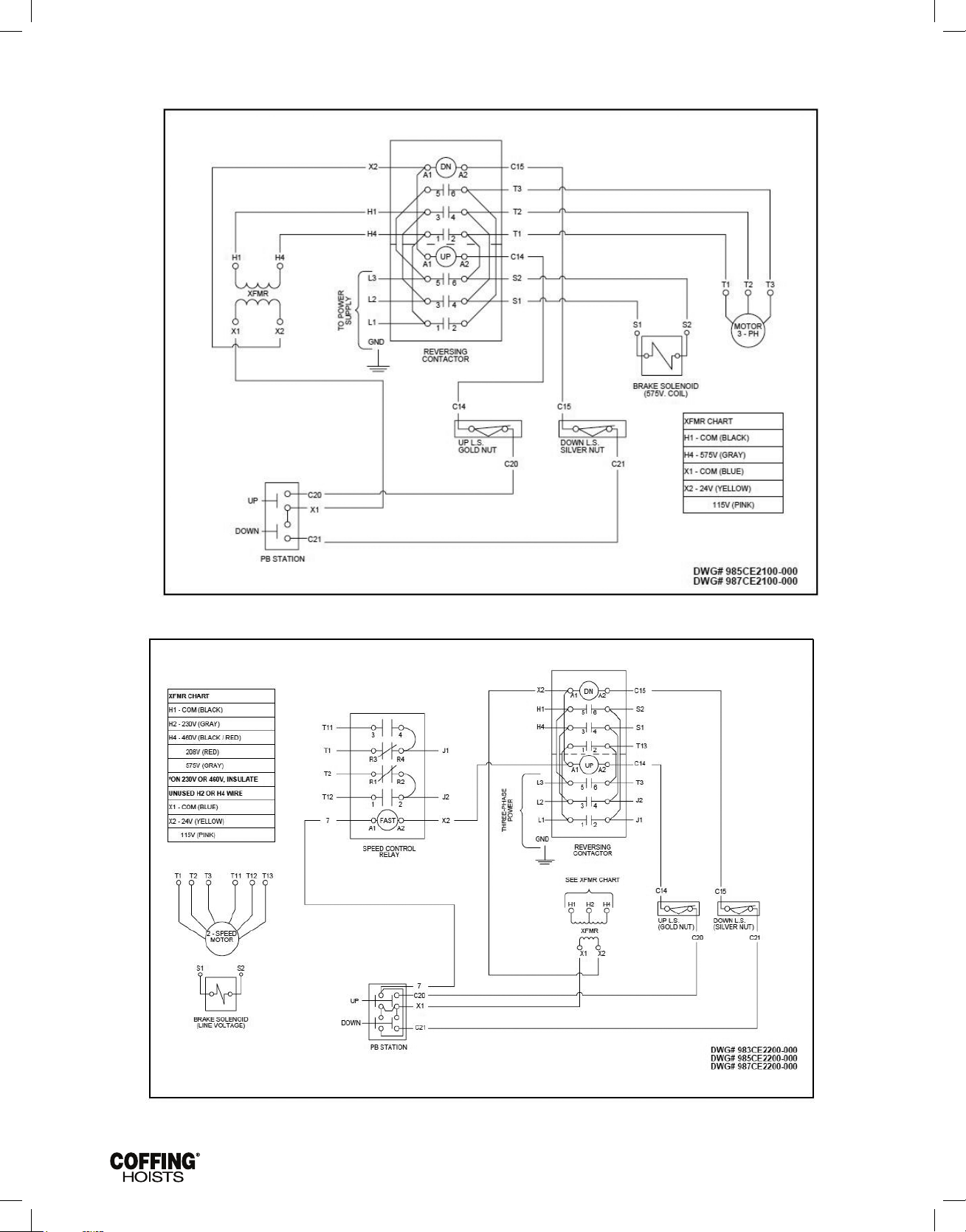
SECTION VII — WIRING CONTINUED
Figure 9C — Wiring Diagram for 1-Speed, 208V and 575V - 3 Phase Models
* Factory supplied diagrams will be numbered beginning with 985 for 575V and 987 for 208V.
* Factory supplied diagrams will be numbered beginning with 983 for 230 or 460V, 985 for 575V and 987 for 208V.
Figure 9D — Wiring Diagram for 2-Speed, 3 Phase Models
16
Page 19

JLC680-2 Rev AA April 2019
SECTION VIII — INSPECTION
INSPECTION
To maintain continuous and satisfactory operation, a regular
inspection procedure must be initiated to replace worn or damaged
parts before they become unsafe. Inspection intervals must be
determined by the individual application and are based on the type
of service to which the hoist will be subjected. The type of service
to which the hoist is subjected can be classied as “Normal”,
“Heavy”, or “Severe”. Normal Service: Involves operation with
randomly distributed loads within the rated load limit, or uniform
loads less than 65 percent of rated load for not more than 25
percent of the time.
HEAVY SERVICE:
Involves operating the hoist within the rated load limit which
exceeds normal service.
SEVERE SERVICE:
Normal or heavy service with abnormal operating conditions or
constant exposure to the elements of nature. Two classes of
inspection - frequent and periodic - must be performed.
FREQUENT INSPECTIONS:
These inspections are visual examinations by the operator or other
designated personnel. Records of such inspections are not required.
The frequent inspections are to be performed monthly for normal
service, weekly to monthly for heavy service, and daily to weekly for
severe service, and they should include those items listed in Table 7.
PERIODIC INSPECTIONS:
These inspections are visual inspections of external conditions by
an appointed person. Records of periodic inspections are to be
kept for continuing evaluation of the condition of the hoist. Periodic
inspections are to be performed yearly for normal service, semiannually for heavy service and quarterly for severe service, and they
are to include those items listed in Table 8.
CAUTION: Any deficiencies found during inspections are to
be corrected before the hoist is returned to service. Also, the
external conditions may show the need for disassembly to
permit a more detailed inspection, which, in turn, may require
the use of nondestructive type testing
PREVENTATIVE MAINTENANCE
In addition to the above inspection procedure, a preventive
maintenance program should be established to prolong the useful
life of the hoist and maintain its reliability and continued safe use.
The program should include the periodic and frequent inspections
with particular attention being paid to the lubrication of the various
components using the recommended lubricants (see Figure 11).
17
Page 20
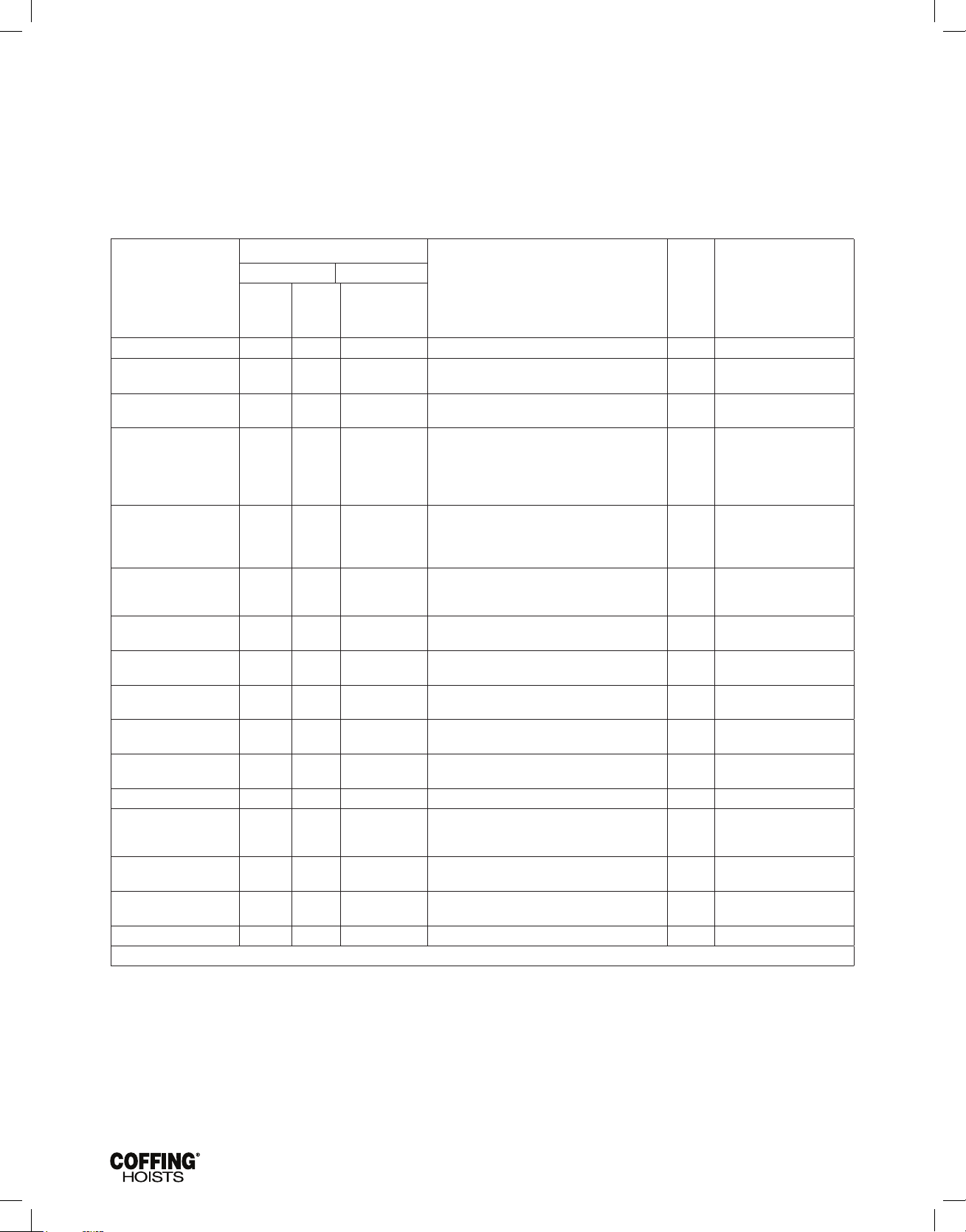
JLC680-2 Rev AA April 2019
SECTION VII — INSPECTION CONTINUED
INSPECTION AND MAINTENANCE CHECK LIST
ELECTRIC POWERED OVERHEAD CHAIN HOIST
Type of Hoist ________________________________________________
Location ____________________________________________________
Manufacturer ________________________________________________
Item
Frequency of Inspection
Frequent Periodic
Daily Monthly
Every 3 Months
to Annually as
defined per
ASME B30.16
Capacity (Tons) ______________________________________________
Original Installation Date ______________________________________
Manufacturer's Serial No. _____________________________________
Possible Deficiencies
Operating Controls * * * Any deficiency causing improper operation
Limit Switches * * * Any deficiency causing improper operation
Pitting or deterioration
Brake Mechanism * * * 1. Slippage or excessive drift
2. Glazing, contamination or excessive wear
Hooks
* * * Excessive throat opening 15% bent or twisted
more than 10 degrees, damaged hook latch, wear,
chemical damage, worn hook bearing. Cracks (use
dye penetrant, magnetic or other suitable detection
method)
Suspension Lug (if used)*
* * * Cracks, excessive wear or other damage which
may impair the strength of the lug. Cracks (use
dye penetrant, magnetic particle or other suitable
detection method)
Chain
* * * Inadequate lubrication, excessive wear or stretch,
cracked, damaged or twisted links, corrosion or
foreign substance
Hook and Suspension Lug
Connections
Pins, Bearings, Bushings
Shafts, Couplings
Nuts, Bolts, Rivets
Sheaves
Housings, Load Block
*
*
Cracks, bending, stripped threads
Excessive wear, corrosion, cracks, distortion
* Looseness, stripped and damaged threads,
corrosion
* Distortion, cracks, and excessive wear. Build-up of
foreign substances
* Cracks, distortion. Excessive wear, internal build-up
of foreign substances
Wiring and Terminals * Fraying, defective insulation
Hoist Reversing Contactor,
other Electrical Apparatus
*
Loose connections, burned or pitted contacts
Ok
Action Required
Supporting Structure and
Trolley (if used)
Nameplates, Decals,
* Damage or wear which restricts ability to support
imposed loads
* Missing, damaged or illegible
Warning Labels
Transmission Lubricant * Low level requires changing
NOTE: Refer to Maintenance and Inspection Sections of this manual for further details.
Figure 10A — Recommended Inspection and Maintenance Check List
NOTE: This inspection and maintenance check list is in accordance with our interpretation of the requirements of the Safety Standard for
Overhead Hoists ASME B30.16. It is, however, the ultimate responsibility of the employer/user to interpret and adhere to the applicable
requirements of this safety standard.
18
Page 21
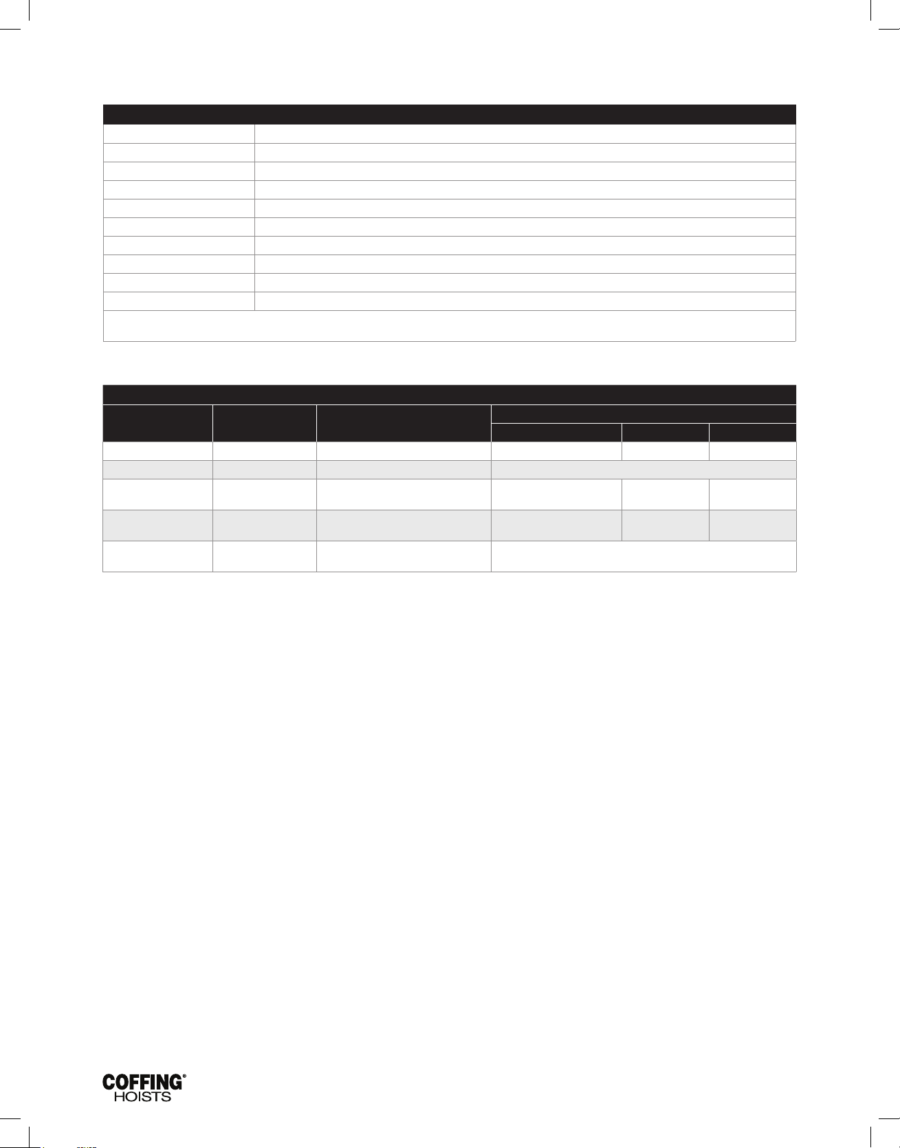
JLC680-2 Rev AA April 2019
SECTION VII — INSPECTION CONTINUED
INSPECTOR’S REPORT
ITEM REMARKS (LIST DEFICIENCIES AND RECOMMENDED ACTION)
Inspector’s
Signature
Date
Inspected
Approved By
Date
Figure 10B - Recommended Inspector’s Report
RECOMMENDED LUBRICATION SCHEDULE* COFFING ELECTRIC POWERED CHAIN HOIST
Page and
Reference No
Component Type of Lubricant
Type of Service and Frequency of Lubrication.
HEAVY NORMAL INFREQUENT
Pages 30 & 31 Ref. No. 9 Load Chain SAE 90 gear oil Daily Weekly Monthly
Pages 28 & 29 Gearing SAE 90 WT extreme pressure (EP) gear oil At periodic inspection (see Figure 10A
Pages 26 & 27
Ref. Nos. 9 & 7
Pages 30 & 31
Ref. No. 19 & 31
Pages 30 & 3 Ref. No. 28
NOTE: All bearings except hook and idler sheave bearings are prelubricated and sealed.
* This lubrication schedule is based on a hoist operating in normal environment conditions. Hoists operating in adverse atmospheres containing excessive heat, corrosive fumes or vapors,
abrasive dust, etc., should be lubricated more frequently.
Limit Switch Shaft
Load Hook Bearing SAE 30 gear oil or motor oil Weekly Monthly Yearly
Idler Sheave Bearing
(Bushing) Assembly
Multi-purpose oil or general purpose
spray
Multi-purpose lithium base
bearing grease - NLGI #2
Monthly Yearly Yearly
At periodic inspection (see Figure 10A)
Figure 11 — Recommended Lubrication Schedule
19
Page 22
JLC680-2 Rev AA April 2019
SECTION IX — REPAIR PARTS LIST
Using “Commercial” or other manufacturer’s parts to repair the
Cofng Hoists may cause load loss.
TO AVOID INJURY:
Use only Cofng supplied replacement parts. Parts may look alike
but Cofng parts are made of specic materials or processed to
achieve specic properties
ORDERING INSTRUCTIONS
The following information must accompany all correspondence
orders for replacement parts:
1. Hoist Model Number from identication plate.
2. Serial number of the hoist stamped below identication plate.
3. Voltage, phase, hertz from the identication plate
4. Length of lift.
5. Part number of part from parts list.
6. Number of parts required.
7. Part name from parts list.
NOTE: When ordering replacement parts, it is recommended
that consideration be given to the need for also ordering such
items as gaskets, fasteners, insulators, etc. These items may
be damaged or lost during disassembly or just unfit for future
use because of deterioration from age or service.
20
Page 23
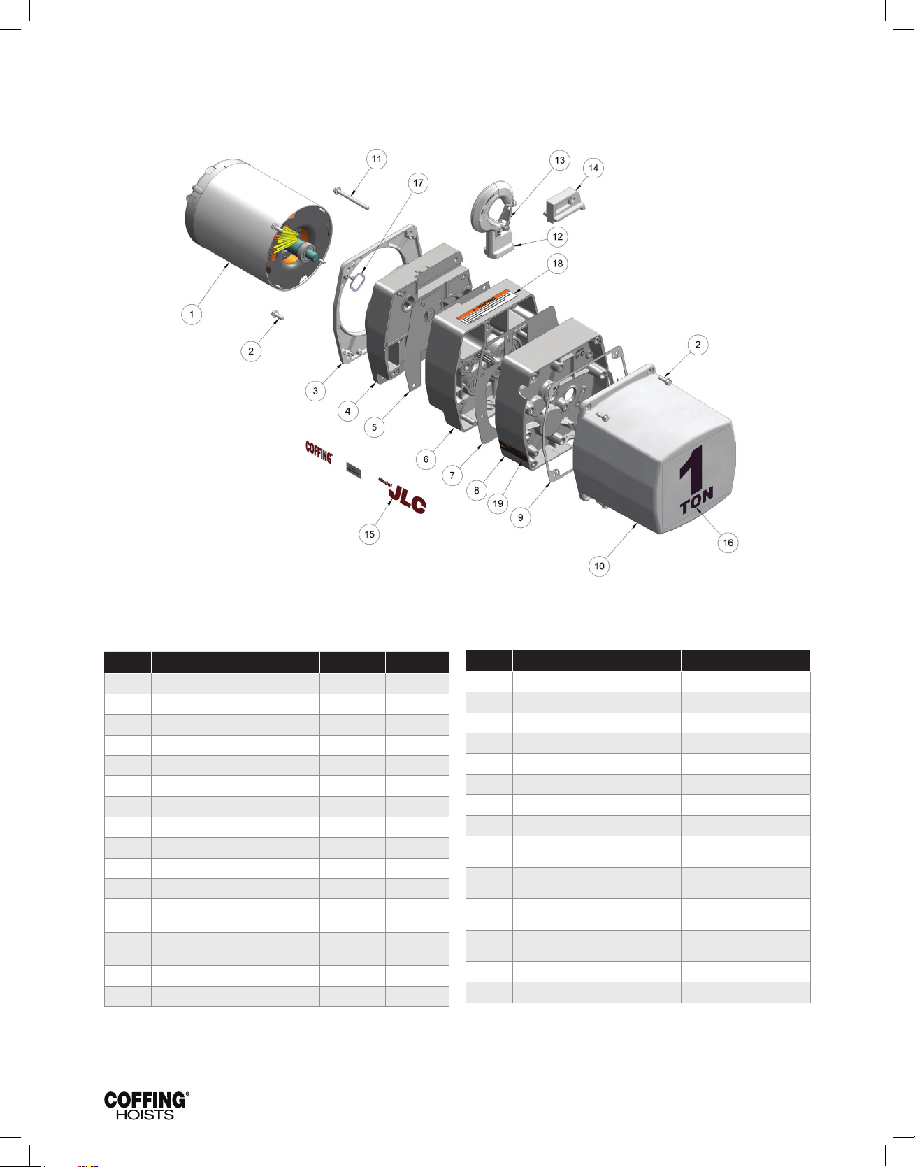
JLC680-2 Rev AA April 2019
FIGURE 12 – BASIC HOIST
Ref. no Description Part No. Qty
1 Motor (See Figures 13 & 14) - 1
2 Cover Screw H2976P 1
3 Trim Cover JM37 1
4 Sheave Housing JM33-1
5 Sheave Housing Gasket JM560-3 1
6 Transmission Housing JM35-1 1
7 Transmission Housing Gasket JM560-2 1
8 Transmission Cover JM34-2 1
9 Electrical Cover Gasket JM563 1
10 Electrical Cover JM36 1
11 Hook Retainer Screw H2709P 1
Top Hook Assembly with Latch Rigid
12
Top Hook Assembly with Latch Swivel
12
13 Latch Kit Assembly 4X1305 2
14 Hook Retainer JM285 1
Hook (Std)
Hook (optional)
3M405A01S 1
51JM1 1
Ref. no Description Part No. Qty
15 JLC & Coffing Decal (Left Hand) JLC677-2L 1
15 JLC & Coffing Decal (Right Hand) JLC677-2R 1
16 Capacity Decal 1/8 ton JM675K01 1
16 Capacity Decal 1/4 ton JM675K02 1
16 Capacity Decal 1/2 ton JM675K05 1
16 Capacity Decal 1 ton JM675K10 1
16 Capacity Decal 2 ton JM675K20 1
17 Spring Washer 360J1 1
Not
Shown
Shown
Shown
Shown
( * )Suspension lug is an option for JLC Models and standard for JLCET Models.
*JLCET Trolley (Lug Mounted) - 1 Ton
Not
Not
Not
*JLCET Trolley (Lug Mounted) 2 Ton 09296 1
Suspension Lug Cross Mounted JM50C 1
Suspension Lug Parallel Mounted 50JM1 1
18 Elevator Warning Label JL687 2
19 Electrical Warning Label 24842 1
& Under
09295 1
21
Page 24
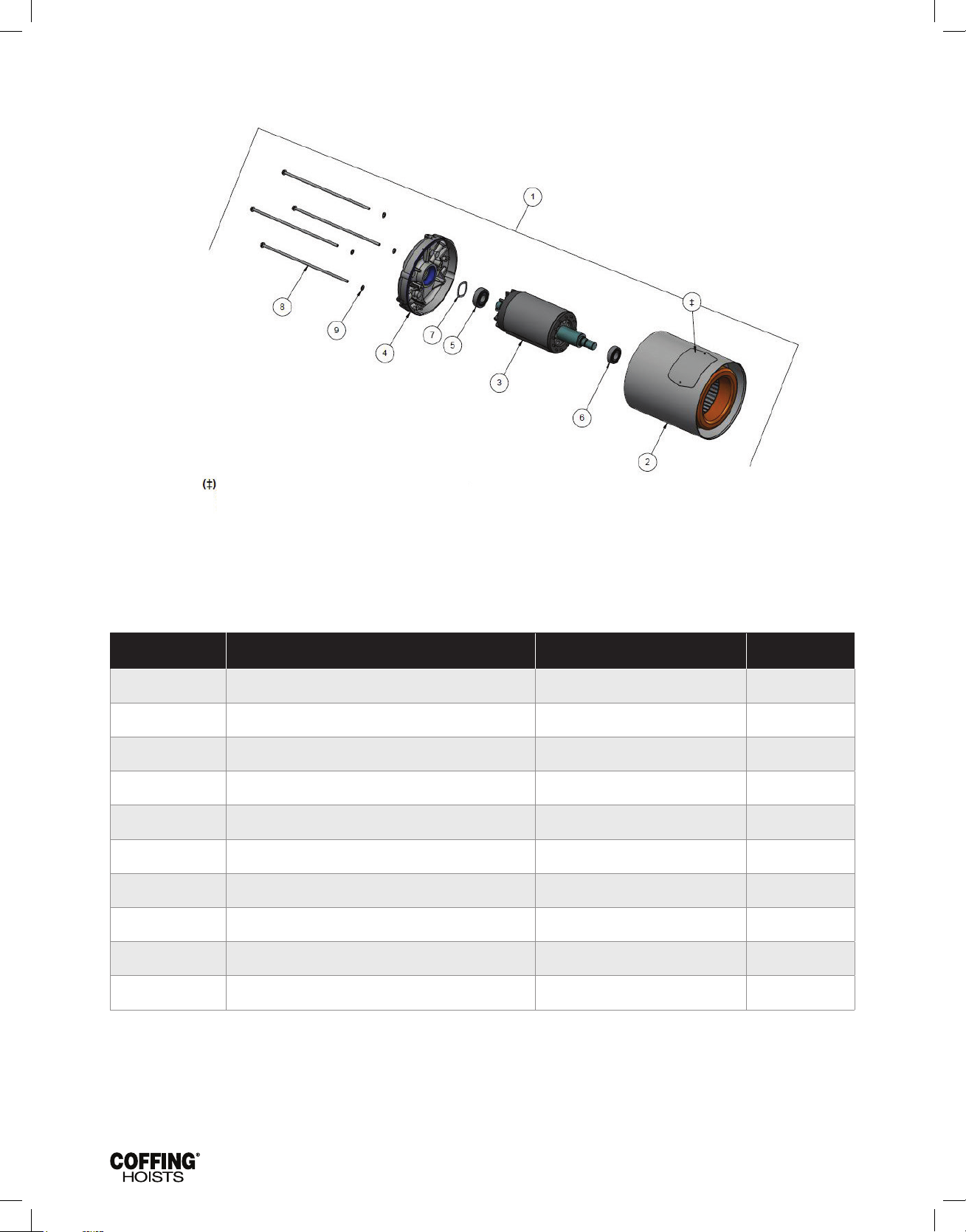
JLC680-2 Rev AA April 2019
FIGURE 13 — HOIST MOTOR, 115/230V — 1 PHASE
Refer to the motor nameplate for part number,
voltage, full load amperage, horsepower, and
other motor information.
Parts List for Hoist Motor, 115/230V - 1 phase
Ref. no Description Part No. Qty
1 Hoist Motor - 1/2 hp, 115/230V-1Ph 861JR12 1
1 Hoist Motor - 1 hp, 115/230V-1Ph 861JR14 1
2 Stator Assembly * 1
3 Rotor Assembly * 1
4 End Shield * 1
5 Rear Bearing 500K3 1
6 Front Bearing * 1
7 Shim Washer JL4301-01 1
8 Thru Bolt HA3100A56 4
9 #10 Spring Lockwasher H4082P 4
*Not available as an individual part.
22
Page 25
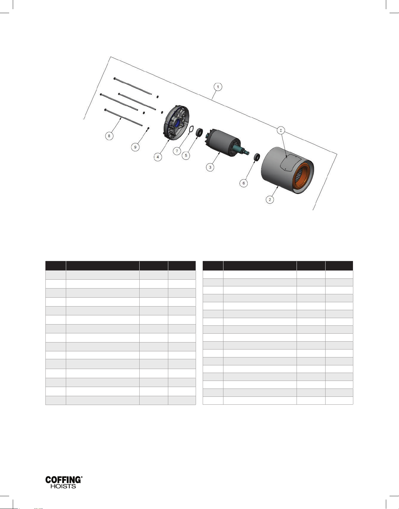
JLC680-2 Rev AA April 2019
FIGURE 14 — HOIST MOTOR — 3 PHASE
(‡) Refer to the motor nameplate for part number,
voltage, full load amperage, horsepower, and
other motor information.
Parts List for Hoist Motor, 3 Phase
Ref. no Description Part No. Qty
1 Hoist Motor (1-Speed) -
1/4 hp, 230/460V-3Ph-60Hz 863JR1 1
1/2 hp, 230/460V-3Ph-60Hz 863JR2 1
1 hp, 230/460V-3Ph-60Hz 863JR4 1
1/4 hp, 575V-3Ph-60Hz 863JR5 1
1/2 hp, 575V-3Ph-60Hz 863JR6 1
1 hp, 575V-3Ph-60Hz 863JR8 1
1/4 hp, 208V-3Ph-60Hz 863JR9 1
1/2 hp, 208V-3Ph-60Hz 863JR10 1
1 hp, 208V-3Ph-60Hz 863JR12 1
Hoist Motor (2-Speed)
1/4 hp, 230V-3Ph-60Hz 873JR1 1
1/2 hp, 230V-3Ph-60Hz 873JR2 1
1 hp, 230V-3Ph-60Hz 873JR4 1
1/4 hp, 460V-3Ph-60Hz 873JR5 1
* Not available as an individual part.
Ref. no Description Part No. Qty
1/2 hp, 460V-3Ph-60Hz 873JR6 1
1 hp, 460V-3Ph-60Hz 873JR8 1
1/4 hp, 575V-3Ph-60Hz 873JR9 1
1/2 hp, 575V-3Ph-60Hz 873JR10 1
1 hp, 575V-3Ph-60Hz 873JR12 1
1/4 hp, 208V-3Ph-60Hz 873JR13 1
1/2 hp, 208V-3Ph-60Hz 873JR14 1
1 hp, 208V-3Ph-60Hz 873JR16 1
2 Stator Assembly * 1
3 Rotor Assembly * 1
4 End Shield * 1
5 Rear Bearing 500K3 1
6 Front Bearing * 1
7 Shim Washer JL4301-01 1
8 Thru Bolt (1-Speed) HA3100A56 4
Thru Bolt (2-Speed) HA3100A71 4
9 #10 Spring Lockwasher H4082P 4
23
Page 26
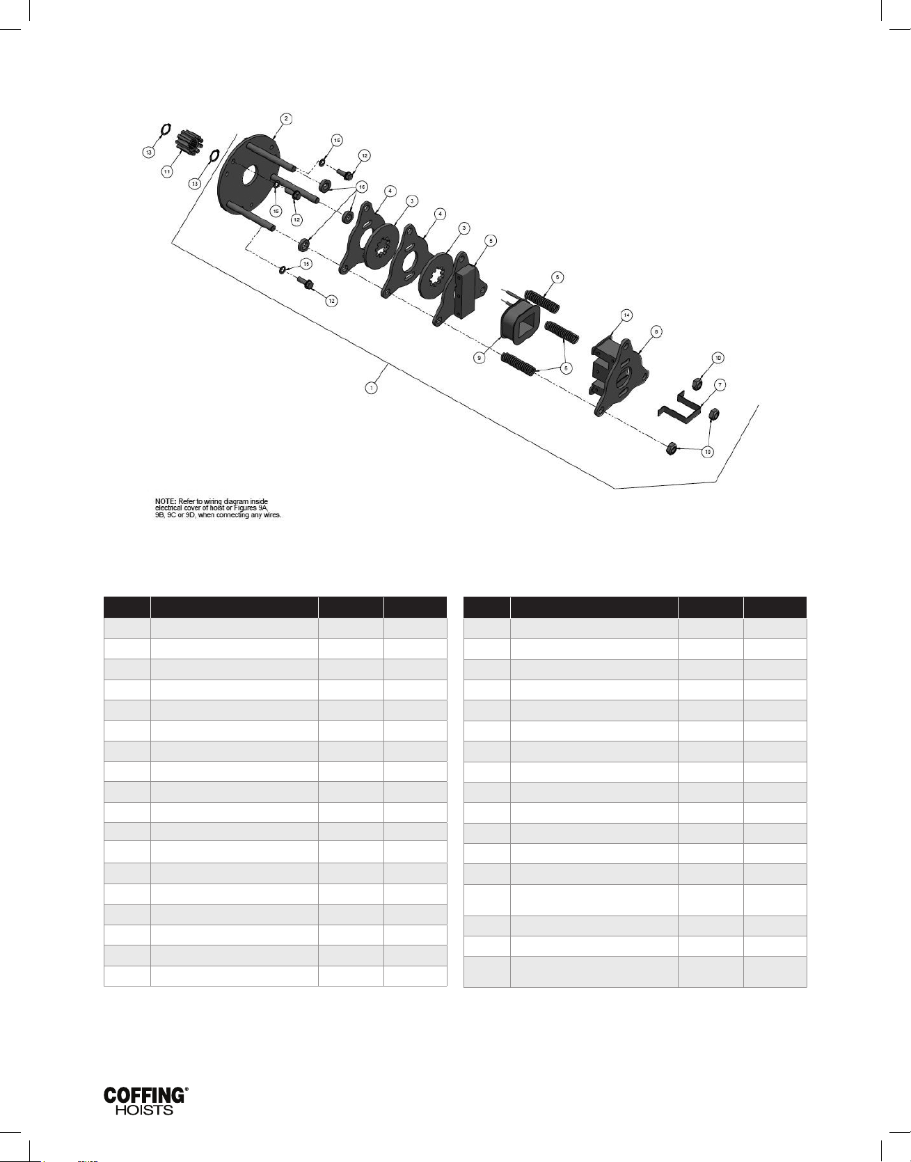
JLC680-2 Rev AA April 2019
FIGURE 15 — BRAKE & SOLENOID PARTS
Parts List for Brake & Solenoid Parts
Ref. no Description Part No. Qty
1 Disc Brake Assembly* —
1 hp,115 Volt 854JM1 1
1/4 & 1/2 hp, 115 Volt 854JM12 1
1 hp, 230 Volt 854JM2 1
1/4 & 1/2 hp, 230 Volt 854JM22 1
1 hp, 460 Volt 854JM3 1
1/4 & 1/2 hp, 460 Volt 854JM32 1
1 hp, 575 Volt 854JM4 1
1/4 & 1/2 hp, 575 Volt 854JM42 1
1 hp, 208 Volt 854JM5 1
1/4 & 1/2 hp, 208 Volt 854JM52 1
2 Plate & Stud Assembly 859JG1 1
3 Brake Disc
1/4 & 1/2 hp 581J1A 2
1 hp 581J1A 3
4 Brake Plate JF291 2
5 Plate & Armature Assembly JF858 1
6 Spring 344J6 3
* Dual Voltage 115/230V hoist models use 115V Brake Assembly and Coil.
* Dual Voltage 230/460V hoist models use 230V Brake Assembly and Coil.
Ref. no Description Part No. Qty
7 Retainer JF710 1
8 Plate & Frame Assembly JF857 1
9 Brake Coil*
115V 853JL1 1
230V 853JL2 1
460V 853JL3 1
575V 853JL4 1
208V 853JL5 1
10 Locknut H3978 3
11 Brake Hub Adapter JM142 1
12 Screw H2976P 3
13 Retaining Ring H5501 2
14 Shading Coil 860J1 2
NOT
SHOWN
15 Lockwasher H4134 3
16 Spacer for 1/4 & 1/2 hp 141J2 3
NOT
SHOWN
Shading Coil Adhesive H7812 1
Warning Decal 676J1 1
24
Page 27
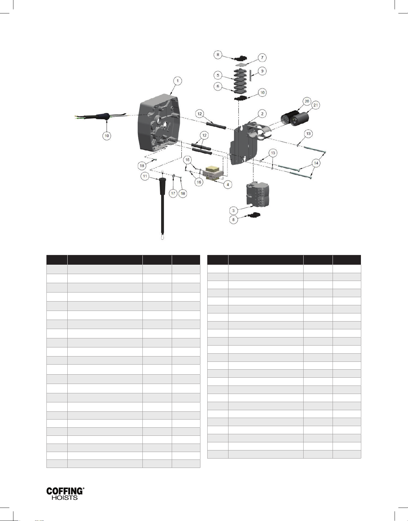
JLC680-2 Rev AA April 2019
FIGURE 16 — ELECTRICAL PARTS — 1-SPEED MODELS
Parts List for Electrical Parts, 1-Speed Models
Ref. no Description Part No. Qty
1 Transmission Cover JM34-2 1
2 Panel Plate 257JM200 1
3 Reversing Contactor*
1/2 hp & under:
24V Coil 28860 1
115V Coil 24799 1
1 hp, 1-Phase:
24V Coil 24791 1
115V Coil 28905 1
1 hp, 3-Phase:
24V Coil 25943 1
115V Coil 24729 1
4 Transformer*
Pri.: 115/230V, Sec.: 24V 821J412 1
Pri.: 115/230V, Sec.: 115V 821J411 1
Pri.: 230/460V, Sec.: 24V 821J432 1
Pri.: 230/460V, Sec.: 115V 821J431 1
Pri.: 575V, Sec.: 24V 821J452 1
Pri.: 575V, Sec.: 115V 821J451 1
Pri.: 208V, Sec.: 24V 821J472 1
Pri.: 208V, Sec.: 115V 821J471 1
5 Terminal Block
115/230V 909J10 2
Ref. no Description Part No. Qty
230/460V 909J10 8
6 Terminal Block 115/230V 909J14 4
7 End Plate
115/230V 909J15 1
230/460V 909J12 1
8 End Clamp
115/230V & 230/460V 909J13 3
Single Voltage Models 909J13 1
9 Marking Strip 909J11 1
10 15 ft Power Cord Assembly
115/230V, 1/2 hp (3 cond.) 951JL1 1
115/230V, 1 hp (3 cond.) 952JL1 1
3-Phase (4 cond.) 953JL1 1
11 PB & Cable Assy (See Figures 18 & 19) — 1
12 Panel Standoff Spacer 200J4 3
13 1/4" Internal-tooth Lockwasher H4134 3
14 1/4-20UNC X 4" Screw H1027P 3
15 8-32UNC X 5/16" Screw H2751 2
16 #8 External-tooth Lockwasher H4158 2
17 1/4" Flatwasher H4002P 1
18 10-24UNC X 1/2" Screw H2970 2
19† Can Mounting Bracket JM811 2
20† SINPAC® Starting Switch 839J3 1
21† Capacitor JL810-4 1
* Coil voltage of the contactor and the secondary voltage of the transformer are the same.
This is referred to as the control voltage. Standard units are supplied with 24V Control.
(†) Single phase units only.
25
Page 28
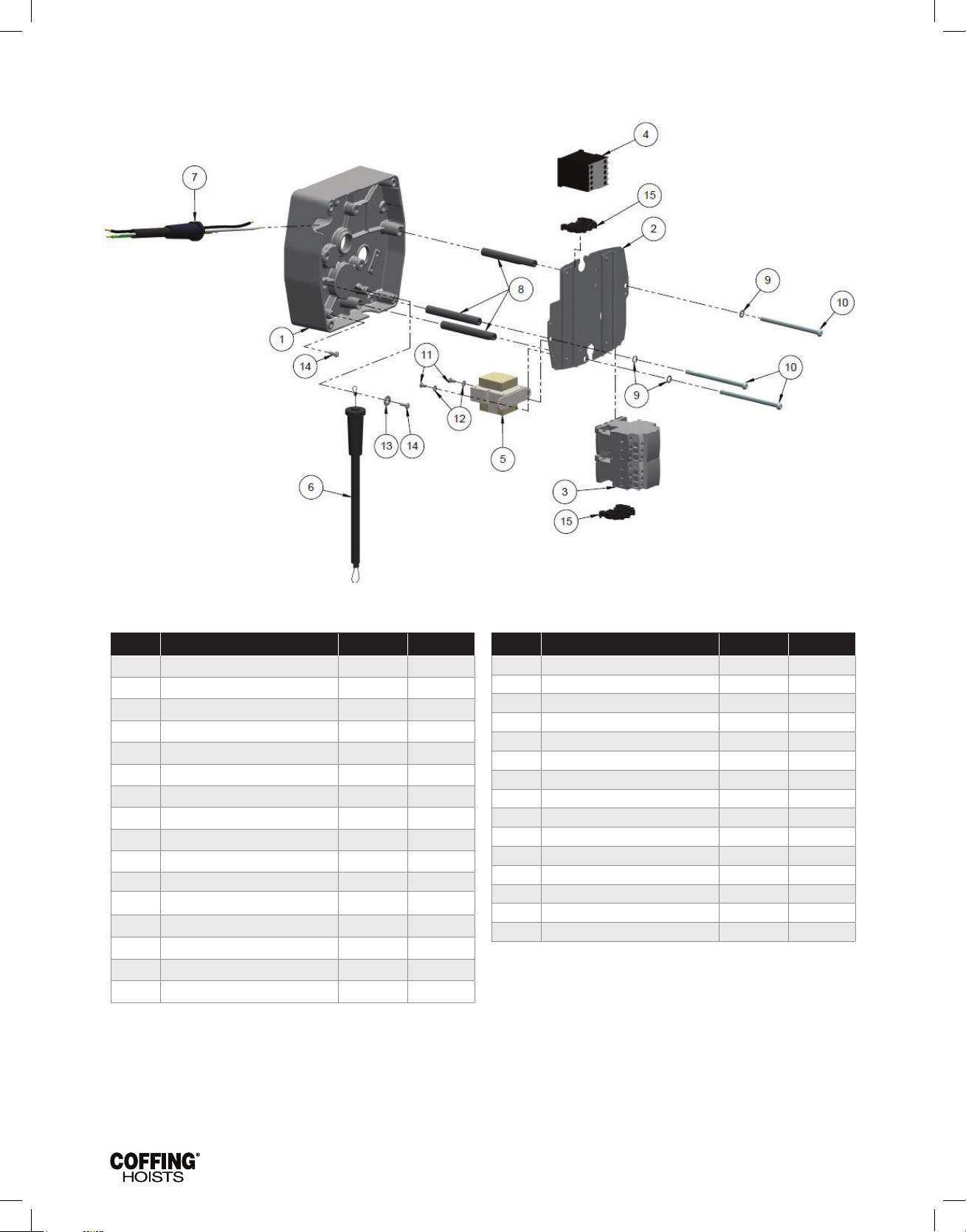
JLC680-2 Rev AA April 2019
FIGURE 17 — ELECTRICAL PARTS — 2-SPEED MODELS
Parts List for Electrical Parts, 2-Speed Models
Ref. no Description Part No. Qty
1 Transmission Cover JM34-2 1
2 Panel Plate 257JM200 1
3 Reversing Contactor*
1/2 hp & under:
24V Coil 28860 1
115V Coil 24799 1
1 hp, 3-Phase:
24V Coil 25943 1
115V Coil 24729 1
4 Speed Control Relay*
1/2 hp, 24V Coil 28878 1
1/2 hp, 115V Coil 28870 1
1 hp, 24V Coil 28885 1
1 hp, 115V Coil 28879 1
5 Transformer*
Pri.: 230/460V, Sec.: 24V 821J432 1
Ref. no Description Part No. Qty
Pri.: 230/460V, Sec.: 115V 821J431 1
Pri.: 575V, Sec.: 24V 821J452 1
Pri.: 575V, Sec.: 115V 821J451 1
Pri.: 208V, Sec.: 24V 821J472 1
Pri.: 208V, Sec.: 115V 821J471 1
6 15 ft Power Cord Assembly 953JL1 1
7 PB & Cable Assy (See Figures 18 & 19) — 1
8 Panel Standoff Spacer 200J4 3
9 1/4" Internal-tooth Lockwasher H4134 3
10 1/4-20UNC X 4" Screw H1027P 3
11 8-32UNC X 5/16" Screw H2751 2
12 #8 External-tooth Lockwasher H4158 2
13 1/4" Flatwasher H4002P 1
14 10-24UNC X 1/2" Screw H2970 2
15 End Clamp 909J13 2
* The coil voltage of the contactors and secondary voltage of the transformer are the same
This is referred to as the control voltage. Standard units are supplied with 24V Control..
26
Page 29
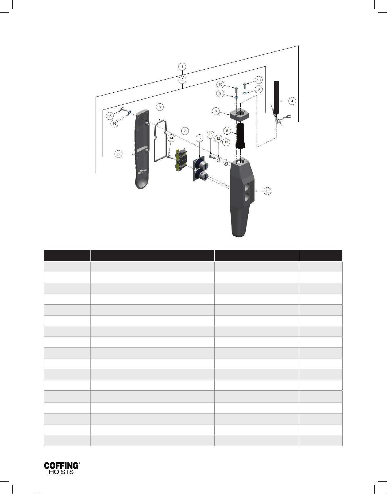
JLC680-2 Rev AA April 2019
FIGURE 18 — 1-SPEED PUSHBUTTON STATION
Parts List for Pushbutton, 1-Speed
Ref. no Description Part No. Qty
1 Pushbutton Station and Control Cable Assembly
6 ft Cable Length PB2100-6 1
11 ft Cable Length PB2100-11 1
16 ft Cable Length PB2100-16 1
2 Pushbutton Station Assembly (2-Button, 1-Speed) 36900R 1
3 Enclosure 36998R 1
4 Control Cable Assembly
6 ft Cable Length PBC2100-6 1
11 ft Cable Length PBC2100-11 1
16 ft Cable Length PBC2100-16 1
Special Drop PBC2100-# 1
5 Grommet 36989 1
6 Button Assembly - -
7 Contact Assembly (includes items 6 & 7) 36987 1
8 Gasket 36986 1
* Hardware Kit (includes items 9 thru 16) 36939 1
Not shown Warning Tag 687K3W 1
( # ) Length of Cable in Feet (pushbutton drop).
27
Page 30
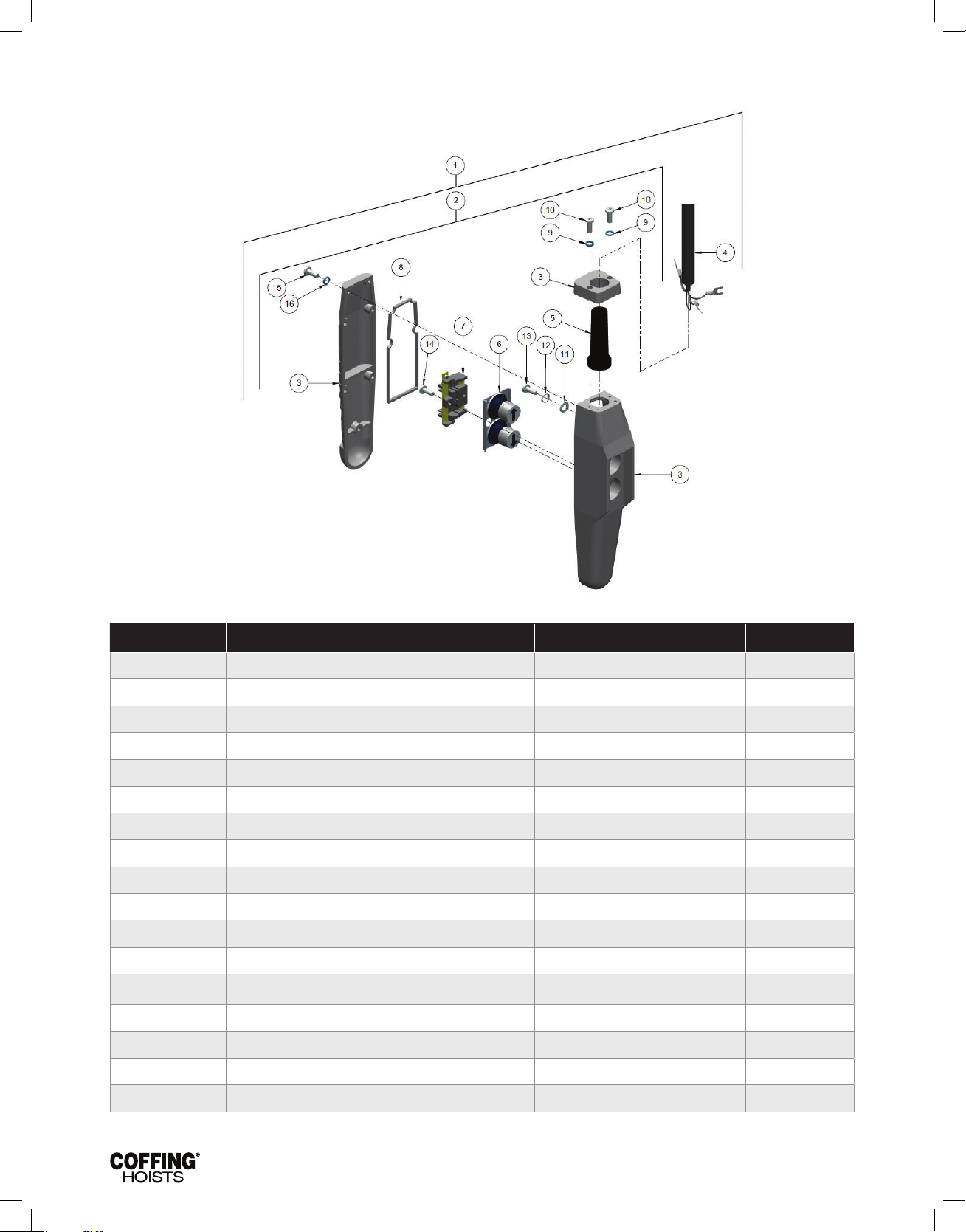
JLC680-2 Rev AA April 2019
FIGURE 19 — 2-SPEED PUSHBUTTON STATION
Parts List for Pushbutton, 2-Speed
Ref. no Description Part No. Qty
1 Pushbutton Station and Control Cable Assembly
6 ft Cable Length PB2200-6 1
11 ft Cable Length PB2200-11 1
16 ft Cable Length PB2200-16 1
2 Pushbutton Station Assembly (2-Button, 2-Speed) 36800R 1
3 Enclosure 36998R 1
4 Control Cable Assembly
6 ft Cable Length PBC2200-6 1
11 ft Cable Length PBC2200-11 1
16 ft Cable Length PBC2200-16 1
Special Drop PBC2200-# 1
5 Grommet 36866 1
6 Button Assembly - -
7 Contact Assembly (includes items 6 & 7) 70964 1
8 Gasket 36986 1
* Hardware Kit (includes items 9 thru 16) Warning Tag 36939 1
Not shown Warning Tag 687K3W 1
( # ) Length of Cable in Feet (pushbutton drop).
28
Page 31
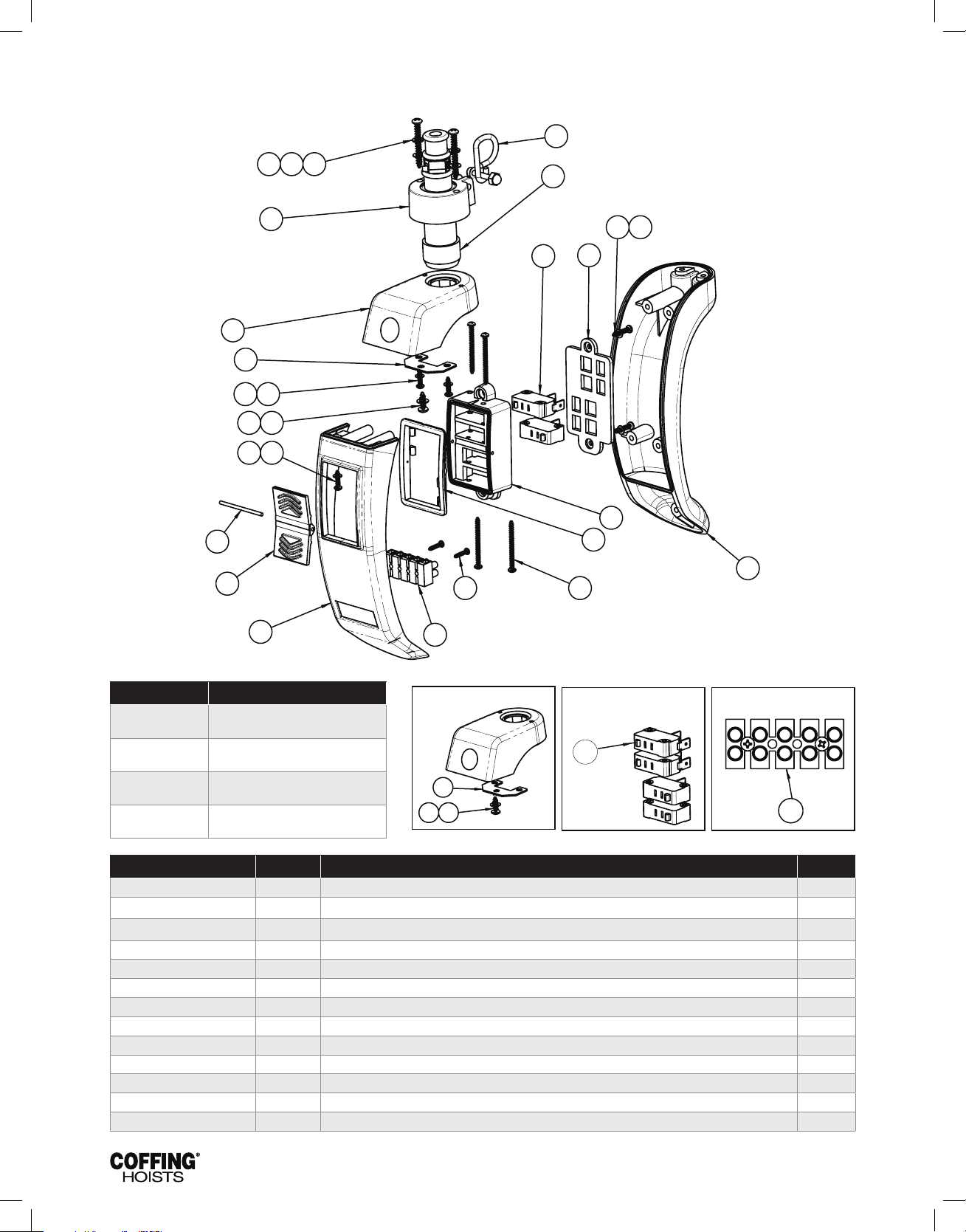
JLC680-2 Rev AA April 2019
FIGURE 20 - COFFING ROCKET UNIVERSAL PENDANT CONTROL
13
1929
24
26
23
4
24***
10
12
7
13
6
3
2829
2
14
26****
15 18
5
25
1627
16
17 27
20
27
1929
*
**
Part No. Description
ECUR-1S
ECUR-2S
ECUR-1S-25P
ECUR-2S-25P
Part No. Ref No. Description Qty.
Rocket Pendant Control - Single-Speed,
No E-stop
Rocket Pendant Control - 2-Speed,
No E-stop
25 PACK: Rocket Pendant Control -
Single-Speed, No E-stop
25 PACK: Rocket Pendant Control -
2-Speed, No E-stop
** Strain Relief Plate
*** 2-Speed Pendants
include 4 Switches
**** Screw Terminal Strip
Ecur-0001 Strain Relief Kit 1
23 Strain Relief 1
3 Strain Relief Collar 1
20 Screw M4 X 1.79 x 33.5 Thd Roll Plstc 2
29 Washer M4 Lk Stt 2
28 Washer M4 x 8mm Od Sst 2
- Instruction Sheet 1
Ecur-0010 Switch Repair Kit, 2 Speed, 4 Switch 1
7 Switch Gasket 1
10 Switch Housing 1
12 Pin Hinge 1
14 Retainer Plate 1
17 Screw M3 X 1.34 x 16mm Lg Thd Roll Plstc 2
29
Page 32
JLC680-2 Rev AA April 2019
Part No. Ref No. Description Qty.
18 Screw M3 x 1.34 x 35mm Lg Thd Roll Plstc 4
24 Pendant Switch 4
25 Rocker Plate 1
27 Washer M3 x 6mm OD Sst 2
- Instruction Sheet 1
ECUR-0011 Switch Repair Kit, 1 Speed, 2 Switch 1
7 Switch Gasket 1
10 Switch Housing 1
12 Pin Hinge 1
14 Retainer Plate 1
17 Screw M3 X 1.34 X 16Mm Lg Thd Roll Plstc 2
18 Screw M3 X 1.34 X 35Mm Lg Thd Roll Plstc 4
24 Pendant Switch 2
25 Rocker Plate 1
27 Washer M3 X 6mm Od Sst 2
- Instruction Sheet 1
ECUR-0020 Enclosure Repair Kit, No E-Stop 1
3 Strain Relief Collar 1
4 Pendant Enclosure Back 1
5 Pendant Enclosure Front 1
6 Pendant Enclosure Top, No E-Stop 1
N/S Cord Gasket 1
Enclosure Hardware Kit 1
13 Strain Relief Plate 1
16 Screw M3 x 1.34 x 12mm Lg Thd Roll Plstc 4
19 Screw M4 x 1.79 x 12mm Lg Thd Roll Plstc 1
18 Screw M4 x 1.79 X 33.5mm Lg Thd Roll Plstc 2
23 Strain Relief 1
27 Washer M3 x 6mm Od Sst 4
29 Washer M4 Lk Sst 2
28 Washer M4 x 8mm Od Sst 3
- Instruction Sheet 1
ECUR-0021 Enclosure Repair Kit, With E-Stop 1
3 Coller Strain Relief Ergo Pendant 1
4 Enclosure Pendant Ergo Back 1
5 Enclosure Pendnat Ergo Front 1
6 Enclosure Pendnat Ergo Top 1
Gasket Silicone Cord Ergo Pendant 1
Hardware Kit Enclosure Ergo Pndnt 1
13 Plate Strain Relief Ergo 1
16 Screw M3 x 1.34 x 12mm Lg Thd Roll Plstc 4
19 Screw M4 x 1.79 x 12mm Lg Thd Roll Plstc 1
18 Screw M4 x 1.79 x 33.5mm Lg Thd Roll Plstc 2
23 Strain Relief 1
27 Washer M3 x 6Mm Od Sst 4
29 Washer M4 Lk Sst 2
28 Washer M4 x 8mm Od Sst 3
- Instruction Sheet 1
ECUR-0030 Pendant Label Kit 1
N/S Instruction Sheet 1
N/S Logo Sticker Sheet 1
62809 N/S Cord Warning Tag 1
23608124 24 Emergency Stop Push Button 1
23608110 2 Cable Bushing 1
30
Page 33
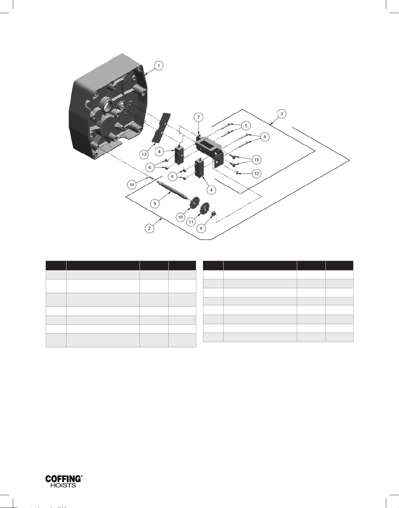
JLC680-2 Rev AA April 2019
FIGURE 21 — LIMIT SWITCH ASSEMBLY
Parts List for Limit Switch Assembly
Ref. no Description Part No. Qty
1 Transmission Cover JM34-2 1
Limit Switch Assembly (Includes items
2
3
4 Switch 815J1 2
5 6-32UNC X 1" Screw H1402P 4
6 6-32UNC Elastic Locknut H3944 4
7
Limit Switch Bracket Assembly
Limit Switch Bracket & Guide Assembly
4-12)
(Includes items 4-8)
(Includes Item 8)
918JG4 1
918JG3 1
JF900-3 1
Ref. no Description Part No. Qty
8 Bushing JF531-4 1
9 Limit Switch Shaft JF117-3S 1
10 Limit Switch Nut (silver) SK6000-63Z 1
11 Limit Switch Nut (gold) SK6000-63W 1
12 Retaining Ring H5520 1
13 Insulator JF754 1
14 Spring JF343-3 1
15 10-24UNC x 1/2" Screw H2970 2
31
Page 34
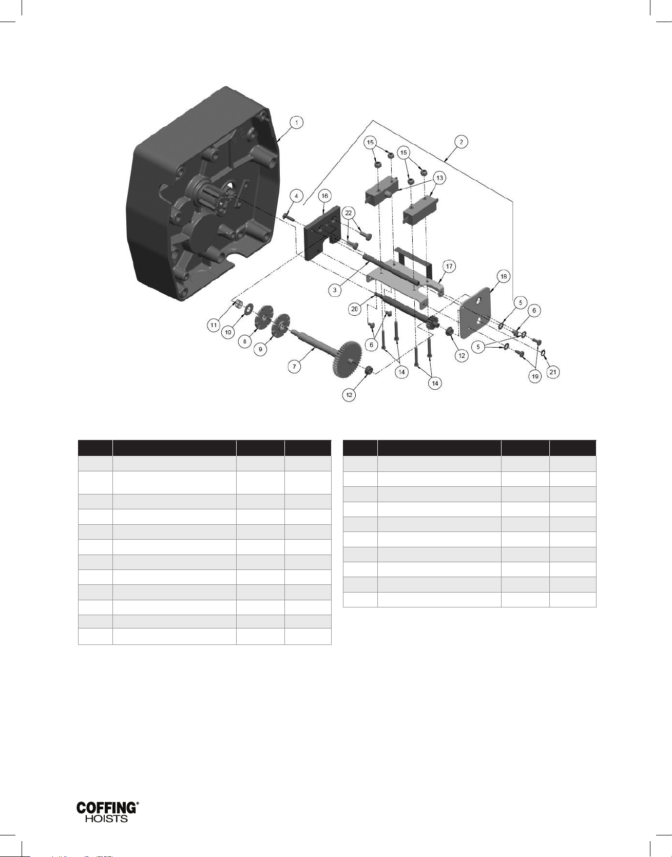
JLC680-2 Rev AA April 2019
FIGURE 22 — LONG LIFT LIMIT SWITCH PARTS
Parts List for Long Lift Limit Switch Parts
Ref. no Description Part No. Qty
1 Transmission Cover JM34-2 1
Limit Switch Assembly (Includes items
2
3 Post 110J14 1
4 8-32UNC X 1/2" Screw H1210 1
5 #8 External-tooth Lockwasher H4158 3
6 8-32UNC X 1/4" Screw 854823 3
7 Limit Switch Shaft & Gear 117JG2 1
8 Limit Switch Nut (gold) SK6000-63W 1
9 Limit Switch Nut (silver) SK6000-63Z 1
10 Thrust Washer 255K16 1
11 Spring PB287 1
12 Bushing JF531-4 2
3-21)
944JG6 1
Ref. no Description Part No. Qty
13 Switch 815J1 2
14 6-32UNC X 1" Screw H1402P 4
15 6-32UNC Elastic Locknut H3944 4
16 Mounting Plate 129J1 1
17 Frame and Guide Assembly 258JG7 1
18 End Plate 258J8 1
19 8-32UNC X 3/8" Screw H2741P 2
20 Drive Pinion 427J1 1
21 Retaining Ring H5520 1
22 10-24UNC X 3/8" Screw H2981P 2
32
Page 35
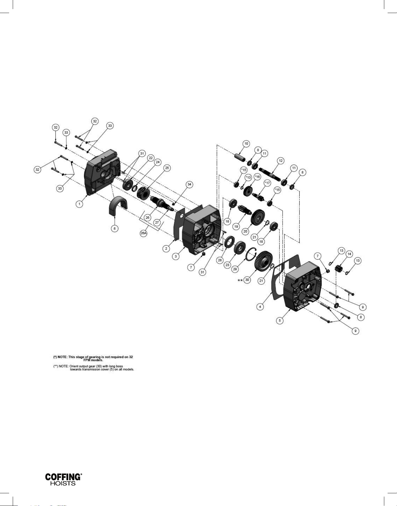
JLC680-2 Rev AA April 2019
FIGURE 23 — TRANSMISSION
33
Page 36
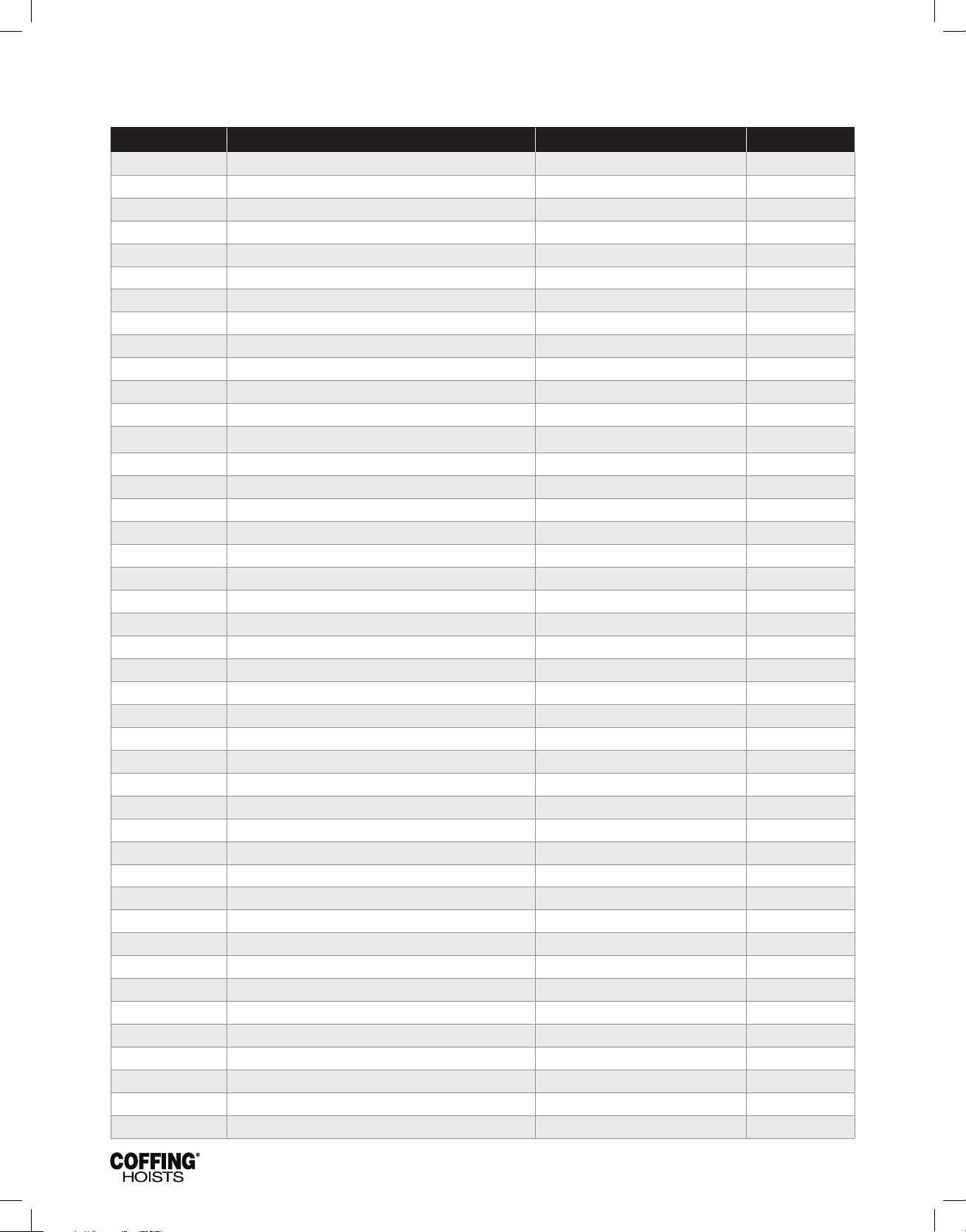
JLC680-2 Rev AA April 2019
FIGURE 23 —TRANSMISSION CONTINUED
Parts List for Transmission
Ref. no Description Part No. Qty
1 Sheave Housing JM33-1 1
2 Sheave Housing Gasket JM560-3 1
3 Transmission Housing JM35-1 1
4 Transmission Housing Gasket JM560-2 1
5 Transmission Cover JM34-2 1
6 Chain Guide JM273 1
7 Oil Plug - Drain/Fill H6297 2
8 Oil Seal 561K2 3
9 Screw Hex Washer Head Self-threading H2693P 5
10 Motor Coupling JM107 1
11 Bearing 500K33 2
12 Input Pinion 8 & 16 fpm JL400C 1
12 Input Pinion 32 fpm JL400-1A 1
13 Retaining Ring H5501 3
14 Brake Hub Adapter JL142 1
15 Bearing for 8 & 16 fpm 500K34 2
16 High Speed Gear for 8 &16 fpm JL426A 1
17 Intermediate Pinion 1/4 & 1/2 ton, 16 fpm JL402B 1
17 Intermediate Pinion 1 & 2 ton JL403B 1
18 Bearing 500K39 2
19 Output Pinion JL401A 1
20 Overload Clutch Assembly 1/8 ton, 32 fpm 591JG22A 1
20 Overload Clutch Assembly 1/4 ton, 16 fpm 591JG25A 1
20 Overload Clutch Assembly 1/4 ton, 32 fpm 591JG22A 1
20 Overload Clutch Assembly 1/2 ton, 16 fpm 591JG16A 1
20 Overload Clutch Assembly 1/2 ton, 32 fpm 591JG21A 1
20 Overload Clutch Assembly 1 & 2 ton 591JG17A 1
21 Retaining Ring H5503 1
22 Bearing 500K28 1
23 Bearing 500K40 1
24 Spacer-Load Sheave JM127 1
25 Load Sheave - 9/32” Dia Chain JF16-3 1
26A Load Sheave Shaft Assembly (Item 26 & 27) 132JM1 1
26 Load Sheave Shaft JM132 1
27 Stub Shaft - Limit Switch Drive JM140 1
28 Oil Seal 011612800 1
29 Retaining Ring H5598 1
30 Output Gear JL421A 1
31 Dowel Pin H5382 4
32 Socket Head Cap Screw 1/4” Dia. S49-10 5
33 Lock Washer, Medium 1/4” Dia. H4084P 5
34 1/4 - 20 UNC Lock Nut (Flexlock Nut Brand Only) H3942P 1
* Oil 1 gt.
34
Page 37
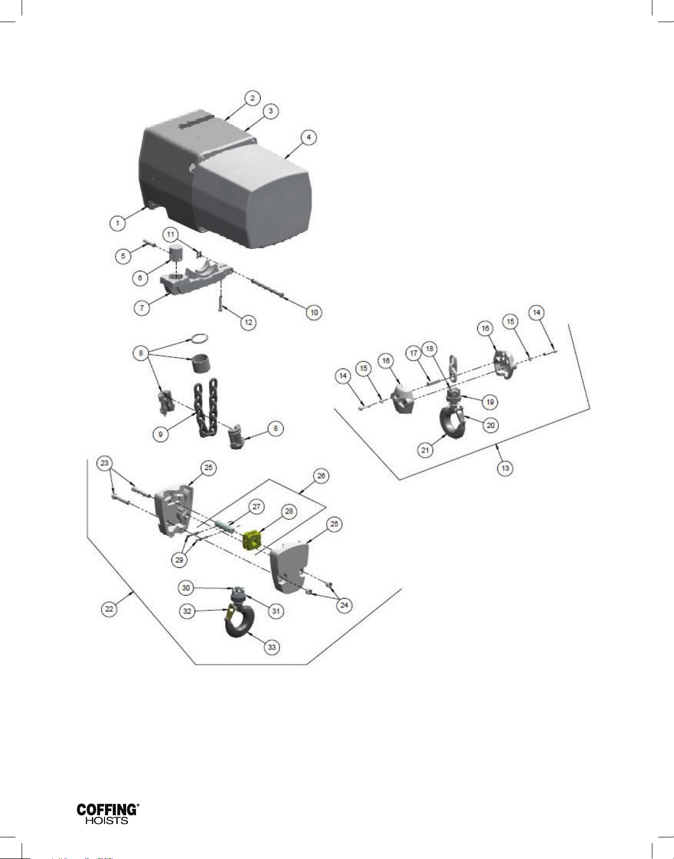
JLC680-2 Rev AA April 2019
FIGURE 24 — CHAINING PARTS
35
Page 38
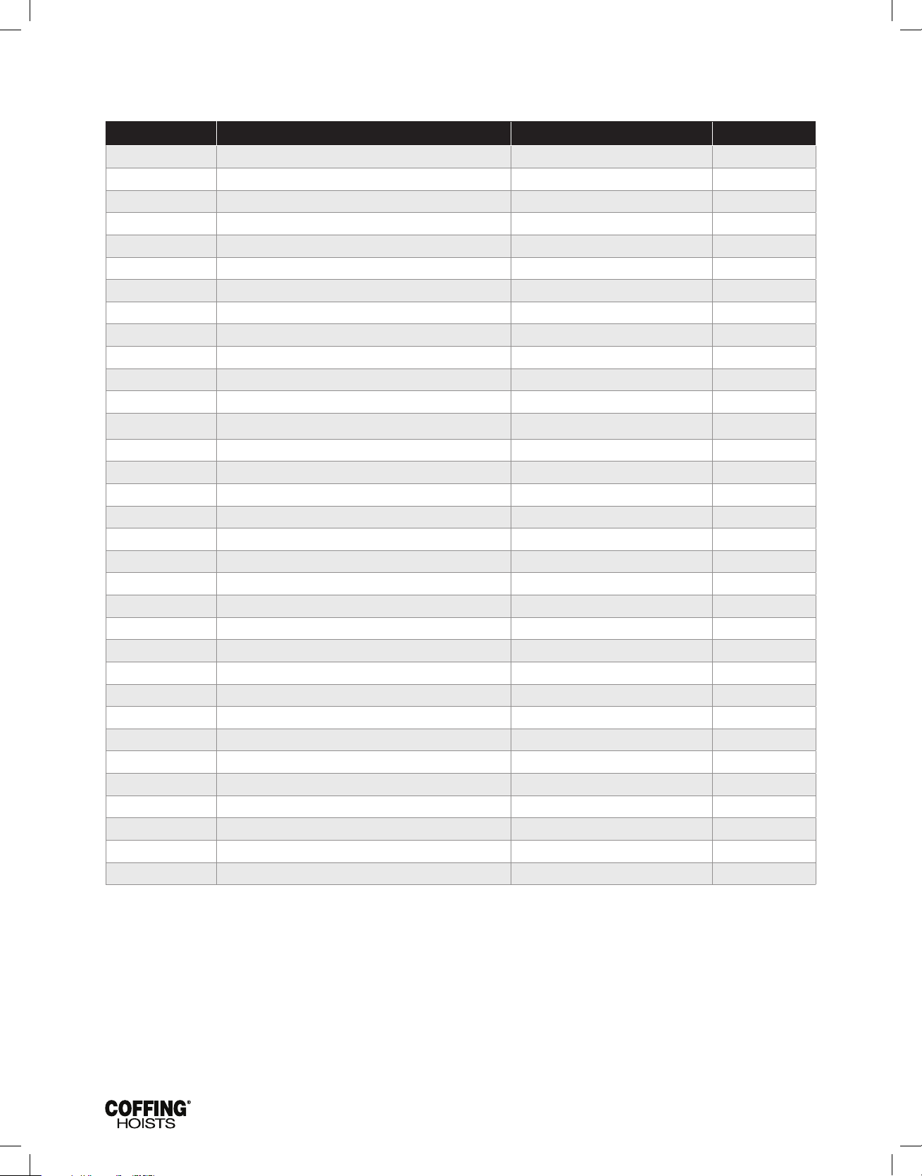
JLC680-2 Rev AA April 2019
FIGURE 24 — CHAINING PARTS CONTINUED
Parts List for Chaining Parts
Ref. no Description Part No. Qty
1 Sheave Housing JM33-1 1
2 Transmission Housing JM35-1 1
3 Transmission Cover JM34-2 1
4 Electrical Cover JM36 1
5 Chain Support Pin (2 ton only) JM111 1
6 Chain Support (2 ton only) JM109 1
7 Chain Stripper JM254 1
8 Chain Stop Kit (Kits include halves, sleeve and retaining ring) 75JG6K 1
9 Load Chain JL19-1 *
10 Attachment Pin JM18-3 1
11 Retaining Clip H5597 1
12 1/4-20UNC x 1¼" Socket Head Cap Screw S49-77 1
13 Bottom Block Assembly 1 ton & Under 913JG3AS 1
14 1/4-20UNC x 1¼" Socket Head Cap Screw S49-77 2
15 1/4" Internal-tooth Lockwasher H4134 2
16 Load Block Frame 30J14 2
17 Load Block Pin 18J8 1
18 Slotted Hex Nut H3986P 1
19 Bearing JF510 1
20 Latch Kit 4X1304 1
21 Bottom Hook Assembly with Latch for 1 Ton & Under 3JG20S 1
22 Bottom Block Assembly for 2 Ton JF914-6 1
23 3/8-24 Hex Locknut H3964P 2
24 Load Block Screw H2403P 2
25 Load Block Frame JF30-1 2
26 Sheave Shaft Assembly JF917-1 1
27 Sheave Shaft JF122-1 1
28 Idler Sheave & Bearing Assembly JF916 1
29 Roll Pin H5234 2
30 3/8-24 Hex Locknut H3991P 1
31 Bearing JF511 1
32 Latch Kit 4X1305 1
33 Bottom Hook Assembly with Latch for 2 Ton 3KG1W 1
* Replacement chain is sold by the foot. For single-chained models, add 2 ft to the lift for the total amount of feet. For double-chained models, double the lift and add 3 ft.
36
Page 39

JLC680-2 Rev AA April 2019
NOTES
37
Page 40
WARRANTY
LIMITATION OF WARRANTIES, REMEDIES AND DAMAGES
INDEMNIFICATION AND SAFE OPERATION
Buyer shall comply with and require its employees to comply with
directions set forth in instructions and manuals furnished by Seller and shall
use and require its employees to follow such instructions and manuals and
to use reasonable care in the use and maintenance of the Goods and any
Replacement Parts. Buyer shall not remove or permit anyone to remove
any warning or instruction signs on the Goods or Replacement Parts. In
the event of personal injury or damage to property or business arising from
the use of the Goods or Replacement Parts, Buyer shall within 48 hours
thereafter give Seller written notice of such injury or damage. Buyer shall
cooperate with Seller in investigating any such injury or damage and in the
defense of any claims arising therefrom.
If Buyer fails to comply with this section or if any injury or damage is
caused, in whole or in part, by Buyer’s failure to comply with applicable
federal or state laws, rules or regulations safety requirements, Buyer
shall indemnify and hold Seller harmless against any claims, loss or
expense for injury or damage arising from the use of the Goods and/or
Replacement Parts.
CMCO Warranty (HOISTS)
A. Columbus McKinnon Corporation (“Seller”) warrants to the original
end user (“Buyer”) that: (a) for a period of one (1) year from the date
of Seller’s delivery of the goods (collectively, the “Goods”) to the carrier,
the electrical components of the Goods will be free from defects in
workmanship and materials; and (b) for the life of the Goods, the
mechanical components of the Goods will be free from defects in
workmanship and materials. In addition, Seller warrants to Buyer
that, for a period of one (1) year from the date of their delivery by
Seller to the carrier, any aftermarket or replacement parts, accessories
or components purchased by Buyer with respect to any Goods
(collectively, “Replacement Parts”) will be free from defects in
workmanship and materials.
B. IN THE EVENT OF ANY BREACH OF ANY SUCH WARRANTY, SELLER’S
SOLE OBLIGATION SHALL BE EXCLUSIVELY LIMITED TO, AT THE OPTION
OF SELLER, REPAIR OR REPLACEMENT, F.O.B. SELLER’S POINT OF
SHIPMENT, OF ANY GOODS OR REPLACEMENT PARTS THAT SELLER
DETERMINES TO HAVE BEEN DEFECTIVE OR, IF SELLER DETERMINES
THAT SUCH REPAIR OR REPLACEMENT IS NOT FEASIBLE, TO A
REFUND OF THE PURCHASE PRICE UPON RETURN OF THE GOODS
OR REPLACEMENT PARTS TO SELLER. NO CLAIM AGAINST SELLER
FOR ANY BREACH OF (i) SUCH WARRANTY WITH RESPECT TO THE
ELECTRICAL COMPONENTS OF ANY GOOD, OR ANY REPLACEMENT
PART, SHALL BE VALID OR ENFORCEABLE UNLESS BUYER’S WRITTEN
NOTICE THEREOF IS RECEIVED BY SELLER WITHIN ONE (1) YEAR FROM
THE DATE OF SELLER’S DELIVERY TO THE CARRIER AND (ii) SUCH
WARRANTY WITH RESPECT TO THE MECHANICAL COMPONENTS OF
ANY GOOD SHALL BE VALID OR ENFORCEABLE UNLESS BUYER’S
WRITTEN NOTICE THEREOF IS RECEIVED BY SELLER WITHIN ONE (1)
YEAR FROM THE DATE THE DATE ANY ALLEGED CLAIM ACCRUES.
EXCEPT FOR THE WARRANTIES SET FORTH ABOVE, SELLER MAKES
NO OTHER WARRANTIES WITH RESPECT TO THE GOODS OR ANY
REPLACEMENT PART, WHETHER EXPRESSED OR IMPLIED, INCLUDING
ANY WARRANTIES OF MERCHANTABILITY, FITNESS FOR A PARTICULAR
PURPOSE, QUALITY AND/OR THOSE ARISING BY STATUTE OR
OTHERWISE BY LAW OR FROM ANY COURSE OF DEALING OR USE OF
TRADE, ALL OF WHICH ARE HEREBY EXPRESSLY DISCLAIMED.
C. IN NO EVENT SHALL SELLER BE LIABLE TO BUYER OR ANY THIRD
PARTY WITH RESPECT TO ANY GOOD OR REPLACEMENT PART,
WHETHER IN CONTRACT, TORT OR OTHER THEORY OF LAW, FOR
LOSS OF PROFITS OR LOSS OF USE, OR FOR ANY INCIDENTAL,
CONSEQUENTIAL, SPECIAL, DIRECT OR INDIRECT DAMAGES,
HOWSOEVER CAUSED. SELLER’S MAXIMUM LIABILITY TO BUYER
WITH RESPECT TO THE GOODS OR ANY REPLACEMENT PART
SHALL IN NO EVENT EXCEED THE PRICE PAID BY BUYER FOR THE
GOODS OR REPLACEMENT PART THAT ARE THE SUBJECT OF THE
APPLICABLE CLAIM.
D. Seller shall not be liable for any damage, injury or loss arising out of the
use of the Goods or any Replacement Part if, prior to such damage, injury
or loss, such Goods or Replacement Parts are: (1) damaged or misused
following Seller’s delivery to the carrier; (2) not maintained, inspected, or
used in compliance with applicable law and Seller’s written instructions
and recommendations; or (3) installed, repaired, altered or modied (a) with
any part or accessory other than those supplied by Seller or (b) without
compliance with such laws, instructions or recommendations.
E. This warranty is limited and provided only to the original end user. Each
Good and Replacement Part must be registered within sixty (60)
days of receipt of each product to establish eligibility. Please register
at www.cmworks.com/hoist-warranty-registration or submit registration
card via US mail.
F. Any action against Seller for breach of warranty, negligence or otherwise
in connection with the electrical components of any Good must be
commenced by Buyer within one (1) year after: (a) the date any alleged
claim accrues; or (b) the date of delivery of the Goods to Buyer,
whichever is earlier. Any action against Seller for breach of warranty,
negligence or otherwise in connection with the mechanical components
of any Good must be commenced by Buyer within one (1) year after the
date any alleged claim accrues. Any action against Seller for breach of
warranty, negligence or otherwise in connection with any Replacement
Part must be commenced by Buyer within one (1) year after: (y) the date
any alleged claim accrues; or (z) the date of delivery of the Replacement
Part to Buyer, whichever is earlier.
G. This warranty is contingent upon Buyer’s proper maintenance and
care of the Goods and/or Replacement Parts, and does not extend to
normal wear and tear. Seller reserves the right, at its option, to void this
warranty in the event of Buyer’s use with the Goods and/or Replacement
Parts of parts or accessories other than those supplied by Seller
Alterations or modifications of equipment and use of nonSeller replacement parts can lead to dangerous operation
and injury.
TO AVOID INJURY:
• Do not alter or modify equipment.
• Do use only factory replacement parts manufactured by Seller.
USA: Ph: (800) 888.0985 • (716) 689.5400 • Fax: (716) 689.5644 • www.cmworks.com
CANADA: Ph: (877) 264.6478
© 2019 Columbus McKinnon Corporation. All Rights Reserved.
•
Fax: (877) 264.6477 • www.cmworks.com
 Loading...