

Columbia ZT54, ZT50 Operator's Manual
4BGF0QFSBUJPO1SBDUJDFTt4FU6Qt0QFSBUJPOt.BJOUFOBODFt4FSWJDFt5SPVCMFTIPPUJOHt8BSSBOUZ
OPERATOR’S MANUAL
3;54FSJFT5SBDUPS.PEFMT;5;5
3&"%"/%'0--08"--4"'&5:36-&4"/%*/4536$5*0/4*/5)*4."/6"-
#&'03&"55&.15*/(5001&3"5&5)*4."$)*/&
'"*-63&50$0.1-:8*5)5)&4&*/4536$5*0/4.":3&46-5*/1&340/"-*/+63:
LES DISTRIBUTIONS RVI LIMITÉE, 2955, JEAN-BAPTISTE DESCHAMPS, LACHINE, QUEBEC H8T 1C5
MTD LLC, P.O. BOX 361131 CLEVELAND, OHIO 44136-0019
Printed In USA
8"3/*/(
769 -04725B
(11.02.10)

To The Owner
Thank You
Please read this entire manual prior to operating the equipment.
It instructs you how to safely and easily set up, operate and
maintain your machine. Please be sure that you, and any other
persons who will operate the machine, carefully follow the
recommended safety practices at all times. Failure to do so could
result in personal injury or property damage.
All information in this manual is relative to the most recent
product information available at the time of printing. Review
this manual frequently to familiarize yourself with the machine,
its features and operation. Please be aware that this Operator’s
Manual may cover a range of product specifications for
various models. Characteristics and features discussed and/or
illustrated in this manual may not be applicable to all models.
The manufacturer reserves the right to change product
specifications, designs and equipment without notice and
without incurring obligation.
Table of Contents
1
This product has met the rigid safety standards of the Outdoor
Power Equipment Institute and an independent testing
laboratory. If you have any problems or questions concerning the
machine, phone your local authorized service dealer.
Throughout this manual, all references to right and left side of the
machine are observed from the operating position.
The engine manufacturer is responsible for all engine-related
issues with regards to performance, power-rating, specifications,
warranty and service. Please refer to the engine manufacturer’s
Owner’s/Operator’s Manual, packed separately with your
machine, for more information.
Safe Operation Practices ........................................ 3
Assembly & Set Up ................................................... 9
Controls & Features ................................................12
Operation ................................................................15
Maintenance & Adjustment................................. 22
Service .................................................................... 28
Record Product Information
Before setting up and operating your new equipment, please
locate the model plate on the equipment and record the
information in the provided area to the right. You can locate the
model plate by looking beneath the seat. This information will be
necessary, should you seek technical support from an authorized
service dealer.
Customer Support
If you have difficulty assembling this product or have any questions regarding the controls, operation or ◊
maintenance of this unit, please call an authorized dealer.
Troubleshooting .................................................... 33
Accessories ............................................................. 34
Replacement Parts ................................................ 36
Warranty ................................................................ 38
Emissions Control Warranty Statement .............. 40
MODEL NUMBER
SERIAL NUMBER
Please have your unit’s model number and serial number ready when you call. ◊
See previous section to locate this information.
2

Important Safe Operation Practices
8"3/*/(This symbol points out important safety instructions which, if not followed,
could endanger the personal safety and/or property of yourself and others. Read and follow
all instructions in this manual before attempting to operate this machine. Failure to comply
with these instructions may result in personal injury.
When you see this symbol. )&&%*548"3/*/(
%"/(&3This machine was built to be operated according to the safe operation practices in
this manual. As with any type of power equipment, carelessness or error on the part of the
operator can result in serious injury. This machine is capable of amputating hands and feet
and throwing objects. Failure to observe the following safety instructions could result in
serious injury or death.
2
General Operation
Read, understand, and follow all instructions on the 1.
machine and in the manual(s) before attempting to
assemble and operate. Keep this manual in a safe place for
future and regular reference and for ordering replacement
parts.
Be familiar with all controls and their proper operation. 2.
Know how to stop the machine and disengage them
quickly.
Never allow children under 14 years of age to operate this 3.
machine. Children 14 and over should read and understand
the instructions and safe operation practices in this manual
and on the machine and should be trained and supervised
by an adult.
Never allow adults to operate this machine without proper 4.
instruction.
To help avoid blade contact or a thrown object injury, 5.
keep bystanders, helpers, children and pets at least 75 feet
from the machine while it is in operation. Stop machine if
anyone enters the area.
Thoroughly inspect the area where the equipment is to be 6.
used. Remove all stones, sticks, wire, bones, toys, and other
foreign objects which could be picked up and thrown by
the blade(s). Thrown objects can cause serious personal
injury.
Plan your mowing pattern to avoid discharge of material 7.
toward roads, sidewalks, bystanders and the like. Also,
avoid discharging material against a wall or obstruction
which may cause discharged material to ricochet back
toward the operator.
Always wear safety glasses or safety goggles during 8.
operation and while performing an adjustment or repair
to protect your eyes. Thrown objects which ricochet can
cause serious injury to the eyes.
Wear sturdy, rough-soled work shoes and close-fitting 9.
slacks and shirts. Loose fitting clothes and jewelry can be
caught in movable parts. Never operate this machine in
bare feet or sandals.
Be aware of the mower and attachment discharge direction 10.
and do not point it at anyone. Do not operate the mower
without the discharge cover or entire grass catcher in its
proper place.
Do not put hands or feet near rotating parts or under the 11.
cutting deck. Contact with the blade(s) can amputate
hands and feet.
A missing or damaged discharge cover can cause blade 12 .
contact or thrown object injuries.
Stop the blade(s) when crossing gravel drives, walks, or 13.
roads and while not cutting grass.
Watch for traffic when operating near or crossing 14.
roadways. This machine is not intended for use on any
public roadway.
Do not operate the machine while under the influence of 15.
alcohol or drugs.
Mow only in daylight or good artificial light.16.
Never carry passengers.17.
Disengage blade(s) before shifting into reverse. Back up 18.
slowly. Always look down and behind before and while
backing to avoid a back-over accident.
Slow down before turning. Operate the machine smoothly. 19.
Avoid erratic operation and excessive speed.
Disengage blade(s), set parking brake, stop engine and 20.
wait until the blade(s) come to a complete stop before
removing grass catcher, emptying grass, unclogging chute,
removing any grass or debris, or making any adjustments.
Never leave a running machine unattended. Always turn 21.
off blade(s), place transmission in neutral, set parking
brake, stop engine and remove key before dismounting.
3

Use extra care when loading or unloading the machine into 22.
a trailer or truck. This machine should not be driven up or
down ramp(s), because the machine could tip over, causing
serious personal injury. The machine must be pushed
manually on ramp(s) to load or unload properly.
Muffler and engine become hot and can cause a burn. Do 23.
not touch.
Check overhead clearances carefully before driving under 24.
low hanging tree branches, wires, door openings etc.,
where the operator may be struck or pulled from the
machine, which could result in serious injury.
Disengage all attachment clutches, depress the brake 25.
pedal completely and shift into neutral before attempting
to start engine.
Your machine is designed to cut normal residential grass of 26.
a height no more than 10”. Do not attempt to mow through
unusually tall, dry grass (e.g., pasture) or piles of dry leaves.
Dry grass or leaves may contact the engine exhaust and/or
build up on the mower deck presenting a potential fire
hazard.
Use only accessories and attachments approved for this 27.
machine by the machine manufacturer. Read, understand
and follow all instructions provided with the approved
accessory or attachment.
Data indicates that operators, age 60 years and above, are 28.
involved in a large percentage of riding mower-related
injuries. These operators should evaluate their ability
to operate the riding mower safely enough to protect
themselves and others from serious injury.
If situations occur which are not covered in this manual, use 29.
care and good judgment. Contact your customer service
representative for assistance.
Slope Operation
Slopes are a major factor related to loss of control and tip-over
accidents which can result in severe injury or death. All slopes
require extra caution. If you cannot back up the slope or if you
feel uneasy on it, do not mow it.
For your safety, use the slope gauge included as part of this
manual to measure slopes before operating this machine on
a sloped or hilly area. If the slope is greater than 15 degrees as
shown on the slope gauge, do not operate this machine on that
area or serious injury could result.
Do:
Mow up and down slopes, not across. Exercise extreme 1.
caution when changing direction on slopes.
Watch for holes, ruts, bumps, rocks, or other hidden 2.
objects. Uneven terrain could overturn the machine. Tall
grass can hide obstacles.
Use slow speed. Choose a low enough speed setting so 3.
that you will not have to stop or shift while on the slope.
Tires may lose traction on slopes even though the brakes
are functioning properly. Always keep machine in gear
when going down slopes to take advantage of engine
braking action.
Follow the manufacturer’s recommendations for wheel 4.
weights or counterweights to improve stability.
Use extra care with grass catchers or other attachments. 5.
These can change the stability of the machine.
Keep all movement on the slopes slow and gradual. Do 6.
not make sudden changes in speed or direction. Rapid
engagement or braking could cause the front of the
machine to lift and rapidly flip over backwards which could
cause serious injury.
Do Not:
Do not turn on slopes unless necessary; then, turn slowly 1.
and gradually downhill, if possible.
Do not mow near drop-offs, ditches or embankments. The 2.
mower could suddenly turn over if a wheel is over the edge
of a cliff, ditch, or if an edge caves in.
Do not try to stabilize the machine by putting your foot on 3.
the ground.
Do not use a grass catcher on steep slopes. 4.
Do not mow on wet grass. Reduced traction could cause 5.
sliding.
Do not tow heavy pull behind attachments (e.g. loaded 6.
dump cart, lawn roller, etc.) on slopes greater than 5
degrees. When going down hill, the extra weight tends
to push the tractor and may cause you to loose control
(e.g. tractor may speed up, braking and steering ability are
reduced, attachment may jack-knife and cause tractor to
overturn).
SECTION 2 — IMPORTANT SAFE OPERATION PRACTICES

Children
Tragic accidents can occur if the operator is not alert to the 1.
presence of children. Children are often attracted to the
machine and the mowing activity. They do not understand
the dangers. Never assume that children will remain where
you last saw them.
Keep children out of the mowing area and in a.
watchful care of a responsible adult other than the
operator.
Be alert and turn machine off if a child enters the b.
area.
To avoid back-over accidents, look behind and down c.
for small children.
Never carry children, even with the blade(s) shut off. d.
They may fall off and be seriously injured or interfere
with safe machine operation.
Use extreme care when approaching blind corners, e.
doorways, shrubs, trees or other objects that may
block your vision of a child who may run into the
path of the machine.
Keep children away from hot or running engines. f.
They can suffer burns from a hot muffler.
Remove key when machine is unattended to g.
prevent unauthorized operation.
Never allow children under 14 years of age to operate this 2.
machine. Children 14 and over should read and understand
the instructions and safe operation practices in this manual
and on the machine and should be trained and supervised
by an adult.
Tow in g
Tow only with a machine that has a hitch designed for 1.
towing. Do not attach towed equipment except at the
hitch point.
Follow the manufacturers recommendation for weight 2.
limits for towed equipment and towing on slopes.
Never allow children or others in or on towed equipment.3.
On slopes, the weight of the towed equipment may cause 4.
loss of traction and loss of control.
Travel slowly and allow extra distance to stop.5.
Do not shift to neutral and coast downhill. 6.
Do not tow heavy pull behind attachments (e.g. loaded 7.
dump cart, lawn roller, etc.) on slopes greater than 5
degrees. When going down hill, the extra weight tends
to push the tractor and may cause you to loose control
(e.g. tractor may speed up, braking and steering ability are
reduced, attachment may jack-knife and cause tractor to
overturn).
Service
Safe Handling of Gasoline:
To avoid personal injury or property damage use extreme 1.
care in handling gasoline. (BTPMJOFJTFYUSFNFMZ
GMBNNBCMFBOEUIFWBQPSTBSFFYQMPTJWF Serious
personal injury can occur when gasoline is spilled on
yourself or your clothes which can ignite. Wash your skin
and change clothes immediately.
Use only an approved gasoline container.a.
Never fill containers inside a vehicle or on a truck b.
or trailer bed with a plastic liner. Always place
containers on the ground away from your vehicle
before filling.
When practical, remove gas-powered equipment c.
from the truck or trailer and refuel it on the ground.
If this is not possible, then refuel such equipment on
a trailer with a portable container, rather than from a
gasoline dispenser nozzle.
Keep the nozzle in contact with the rim of the fuel d.
tank or container opening at all times until fueling is
complete. Do not use a nozzle lock-open device.
Extinguish all cigarettes, cigars, pipes and other e.
sources of ignition.
Never fuel machine indoors.f.
Never remove gas cap or add fuel while the engine g.
is hot or running. Allow engine to cool at least two
minutes before refueling.
Never over fill fuel tank. Fill tank to no more than ½ h.
inch below bottom of filler neck to allow space for
fuel expansion.
Replace gasoline cap and tighten securely.i.
If gasoline is spilled, wipe it off the engine and j.
equipment. Move machine to another area. Wait 5
minutes before starting the engine.
To reduce fire hazards, keep machine free of grass, k.
leaves, or other debris build-up. Clean up oil or fuel
spillage and remove any fuel soaked debris.
Never store the machine or fuel container inside l.
where there is an open flame, spark or pilot light
as on a water heater, space heater, furnace, clothes
dryer or other gas appliances.
Allow a machine to cool at least five minutes before m.
storing.
General Service
Never run an engine indoors or in a poorly ventilated area. 1.
Engine exhaust contains carbon monoxide, an odorless,
and deadly gas.
Before cleaning, repairing, or inspecting, make certain the 2.
blade(s) and all moving parts have stopped. Disconnect the
spark plug wire and ground against the engine to prevent
unintended starting.
SECTION 2 — IMPORTANT SAFE OPERATION PRACTICES

Periodically check to make sure the blades come to 3.
complete stop within approximately (5) five seconds after
operating the blade disengagement control. If the blades
do not stop within the this time frame, your machine
should be serviced professionally by an authorized Service
Dealer.
Regularly check the safety interlock system for proper 4.
function, as described later in this manual. If the safety
interlock system does not function properly, have your
machine serviced professionally by an authorized dealer.
Check the blade(s) and engine mounting bolts at frequent 5.
intervals for proper tightness. Also, visually inspect blade(s)
for damage (e.g., excessive wear, bent, cracked). Replace
the blade(s) with the original equipment manufacturer’s
(O.E.M.) blade(s) only, listed in this manual. “Use of parts
which do not meet the original equipment specifications
may lead to improper performance and compromise
safety!”
Mower blades are sharp. Wrap the blade or wear gloves, 6.
and use extra caution when servicing them.
Keep all nuts, bolts, and screws tight to be sure the 7.
equipment is in safe working condition.
Never tamper with the safety interlock system or other 8.
safety devices. Check their proper operation regularly.
After striking a foreign object, stop the engine, disconnect 9.
the spark plug wire(s) and ground against the engine.
Thoroughly inspect the machine for any damage. Repair
the damage before starting and operating.
Never attempt to make adjustments or repairs to the 10.
machine while the engine is running.
Grass catcher components and the discharge cover are 11.
subject to wear and damage which could expose moving
parts or allow objects to be thrown. For safety protection,
frequently check components and replace immediately
with original equipment manufacturer’s (O.E.M.) parts only,
listed in this manual. “Use of parts which do not meet the
original equipment specifications may lead to improper
performance and compromise safety!”
Do not change the engine governor settings or over-speed 12 .
the engine. The governor controls the maximum safe
operating speed of the engine.
Maintain or replace safety and instruction labels, as 13.
necessary.
Observe proper disposal laws and regulations for gas, oil, 14.
etc. to protect the environment.
According to the Consumer Products Safety Commission 15 .
(CPSC) and the U.S. Environmental Protection Agency (EPA),
this product has an Average Useful Life of seven (7) years,
or 270 hours of operation. At the end of the Average Useful
Life have the machine inspected annually by an authorized
service dealer to ensure that all mechanical and safety
systems are working properly and not worn excessively.
Failure to do so can result in accidents, injuries or death.
Do not modify engine
To avoid serious injury or death, do not modify engine in any
way. Tampering with the governor setting can lead to a runaway
engine and cause it to operate at unsafe speeds. Never tamper
with factory setting of engine governor.
Notice Regarding Emissions
Engines which are certified to comply with California and federal
EPA emission regulations for SORE (Small Off Road Equipment)
are certified to operate on regular unleaded gasoline, and
may include the following emission control systems: Engine
Modification (EM) and Three Way Catalyst (TWC) if so equipped.
Spark Arrestor
8"3/*/(This machine is equipped with an
internal combustion engine and should not be used
on or near any unimproved forest-covered,
brushcovered or grass-covered land unless the
engine’s exhaust system is equipped with a spark
arrester meeting applicable local or state laws (if
any).
If a spark arrester is used, it should be maintained in effective
working order by the operator.
A spark arrester for the muffler is available through your nearest
engine authorized service dealer.
8"3/*/( Your Responsibility—Restrict the use of this power machine to persons who read, understand and
follow the warnings and instructions in this manual and on the machine.
6 SECTION 2 — IMPORTANT SAFE OPERATION PRACTICES
SAVE THESE INSTRUCTIONS!
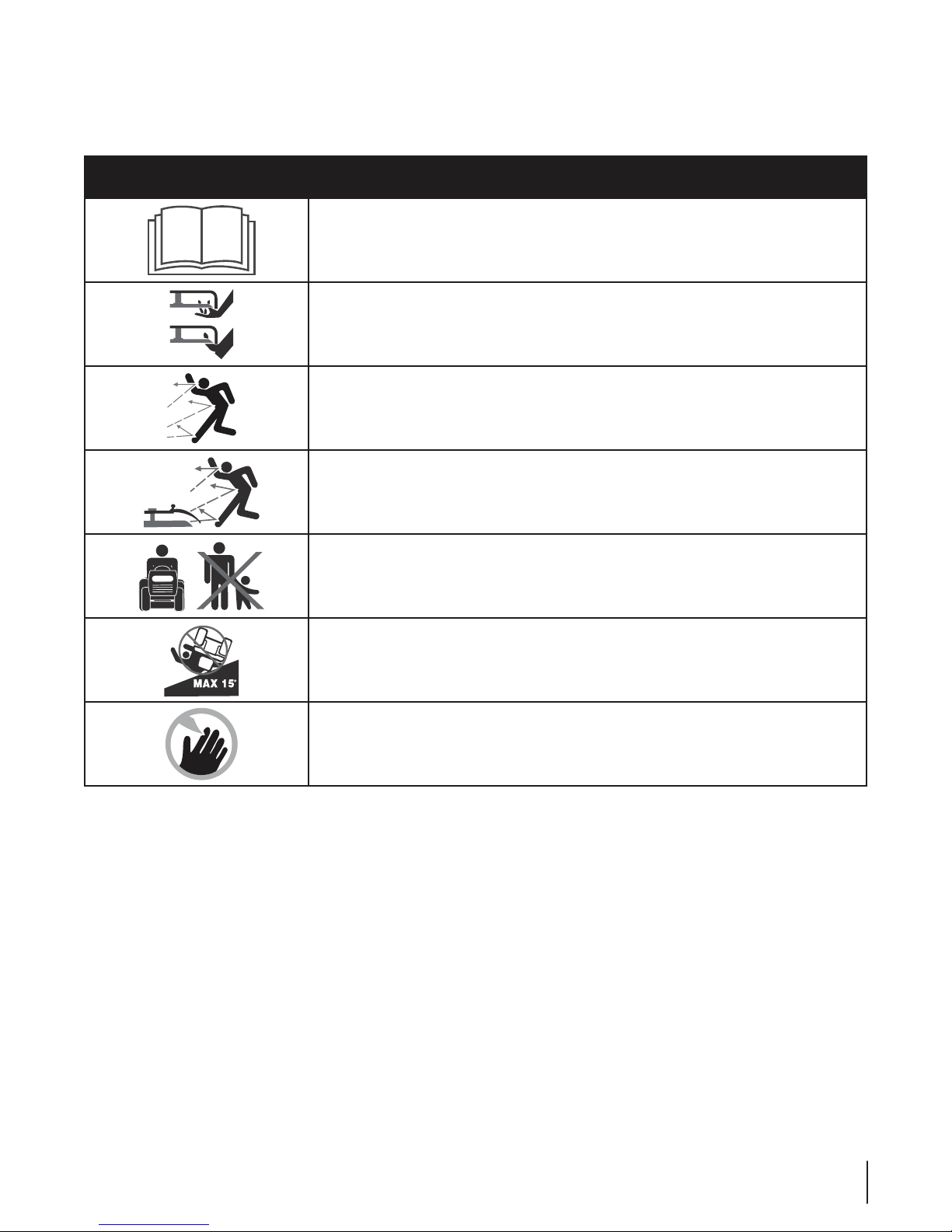
Safety Symbols
This page depicts and describes safety symbols that may appear on this product. Read, understand, and follow all instructions on the
machine before attempting to assemble and operate.
Symbol Description
READ THE OPERATOR’S MANUAL(S)
Read, understand, and follow all instructions in the manual(s) before attempting to
assemble and operate.
WARNING— ROTATING BLADES
Do not put hands or feet near rotating parts or under the cutting deck. Contact with the
blade(s) can amputate hands and feet.
WARNING—THROWN OBJECTS
This machine may pick up and throw and objects which can cause serious personal injury.
WARNING—THROWN OBJECTS
This machine may pick up and throw and objects which can cause serious personal injury.
BYSTANDERS
Keep bystanders, helpers, children and pets at least 75 feet from the machine while it is in
operation.
WARNING— SLOPE OPERATION
Do not operate this machine on a slope greater than 15 degrees.
DANGER — ROTATING BLADES
To reduce the risk of injury, keep hands and feet away. Do not operate unless discharge cover
or grass catcher is in its proper place. If damaged, replace immediately.
7SECTION 2 — IMPORTANT SAFE OPERATION PRACTICES
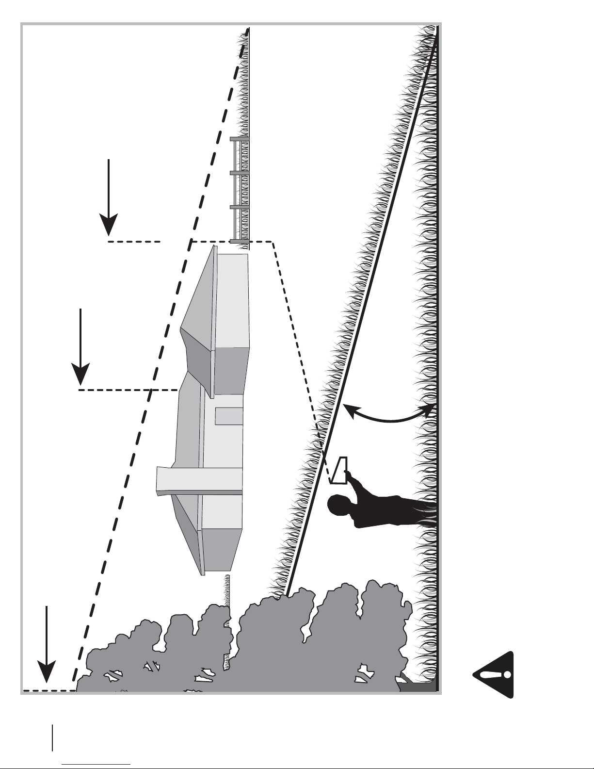
or a fence post
or a corner of a building...
Fold along dotted line (represents a 15° slope)
15°
Sight and hold this level with a vertical tree...
8 SECTION 2 — IMPORTANT SAFE OPERATION PRACTICES
8"3/*/(Do not operate your lawn mower on such slopes. Do not mow on inclines with a slope in excess of 15 degrees
(a rise of approximately 2-1/2 feet every 10 feet). A riding mower could overturn and cause serious injury. Operate riding
mowers up and down slopes, never across the face of slopes.
Use this page as a guide to determine slopes where you may not operate safely.
Assembly & Set-Up
Pull Out Bypass
Rod Then Lower
Into Slot
Keyhole Slot
RH Transmission
Bypass Rod
Push Nuts
Flange Lock Nuts
Carriage Bolts
Contents of Crate
3
One Lawn Tractort One Oil Drain Hose (If Equipped)t
One RZT Tractor Operator’s Manualt One Engine Operator’s Manualt Discharge Chute (42” Only)t
NOTE: This Operator’s Manual covers several models. Tractor
features may vary by model. Not all features in this manual are
applicable to all tractor models and the tractor depicted may
differ from yours.
Lower Deck Discharge Chute Deflector
Tractor Preparation
Remove the upper crating material from the shipping pallet, and
cut any bands or tie straps securing the tractor to the pallet.
Use the lift handle to raise the deck to its highest position.
Engage the transmission bypass rods on each side of the
tractor; then carefully roll the tractor off the shipping pallet.
The transmission bypass rods (one for each the RH and LH
transmission) are located beneath the frame platform, just inside
each rear wheel. Disengage the bypass rods. See Fig. 3-1.
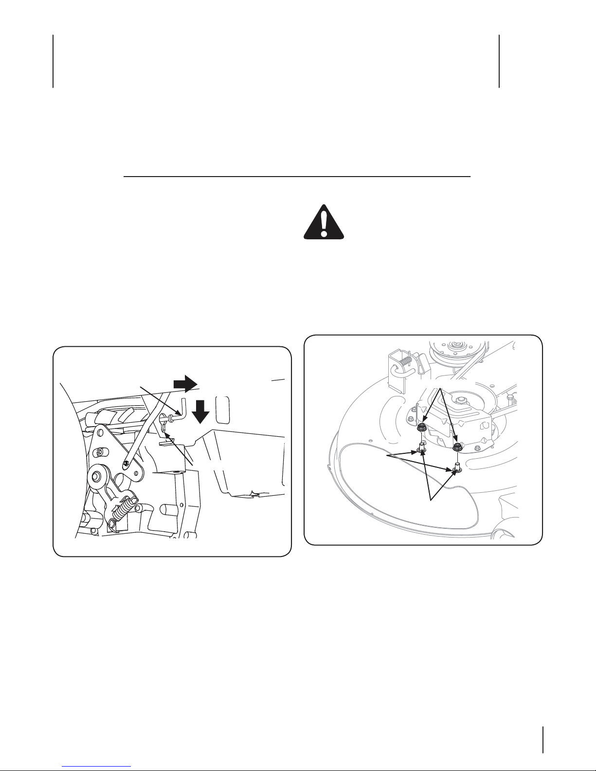
On 42” Decks the discharge chute deflector must be installed
before operating the mower.
Remove the keys that are attached with a zip tie to the 1.
chute bracket.
Remove the flange lock nuts from the deck. Do not remove 2.
the push nuts or carriage bolts, leaving them in place will
aid in installing the chute. See Fig. 3-2.
One Deck Wash Hose Coupler t
WARNING! Never operate the mower deck without
the chute deflector installed and in the down
position.
Figure 3-1
Remove the deck wash system nozzle adapter and oil drain tube
from the manual bag and store for future use.
Figure 3-2
9
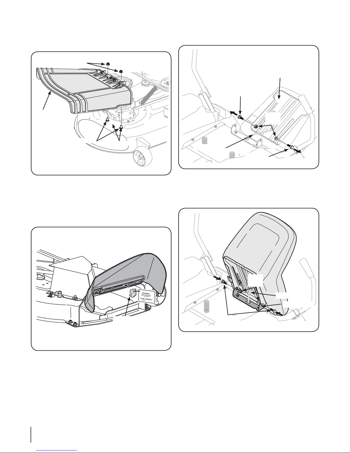
Install the discharge chute deflector using the carriage 3.
Shipping
Brace
Discharge
Chute
Deflector
Flange Lock Nuts
Push Nuts
Carriage Bolts
Wire Harness
Seat Pan
Shoulder
Bolt
Lock
Nuts
Shoulder
Bolt
Wire Harness
Seat Bracket
Shoulder
Bolts
Lock
Nuts
bolts, push nuts and flange lock nuts as shown in Fig. 3-3
and securely tighten the hardware.
Figure 3-3
On 50” and 54” decks check the mower deck for a shipping
brace (with tag) that may be holding the chute deflector
upward for shipment. If a brace is present, it must be removed
before operating the tractor. Holding the chute deflector fully
upward, remove the shipping brace by grasping it and rotating it
clockwise. Lower the chute deflector. See Fig. 3-4.
Remove the two shoulder bolts and lock nuts in the seat 2.
pan as shown in Fig. 3-5.
Figure 3-5
Rotate the seat into position and secure the seat into place 3.
with the previously removed shoulder bolts and lock nuts.
Be careful not to crimp or damage the wire harness while
installing the seat. See Fig. 3-6.
Figure 3-4
Install Operator’s Seat
To install the seat proceed as follows:
NOTE: The seat is shipped with the seat switch and seat pan attached.
NOTE: Be careful not to cut the wiring harness connecting the
seat and the seat switch in the bottom of the seat.
10 SECTION 2— ASSE MBLY & SET-UP
Cut any straps securing the seat assembly and the drive 1.
control levers to the tractor. Remove any packing material.
Figure 3-6
Position Drive Control levers
The drive control levers of the tractor are lowered for shipping
purposes. The flange lock nuts, hex screws, and flat washers that
normally secure the control levers in their operating position
are unfastened and installed in the slotted holes of the control
levers for shipment. The control levers must be repositioned to
operate the tractor. To reposition the control levers for operation,
proceed as follows:
Remove the hex screw, flat washer, and flange lock nut 1.
from the slot of one of the drive control levers.

Lift and swing that control lever upward until the slotted 2.
Control Lever
Flange
Lock Nut
Slotted Hole
Washer
Hex Screw
Lift Control
Lever Upward
Pivot
Bracket
hole in the lever bracket aligns with one of the holes in the
pivot bracket. See Fig. 3-7.
Remove the plastic cover, if present, from the positive 1.
battery terminal and attach the red cable to the positive
battery terminal (+) with the bolt and hex nut. See Fig. 3-8.
Figure 3-7
Slide the flat washer onto the hex screw. From the outside, 3.
insert the hex screw with washer through the control lever
slot and the hole of the pivot bracket. Secure with the
flange lock nut. See Fig. 3-7.
Note the relative position of the control lever to the pivot 4.
bracket, then repeat the previous steps to reposition the
other control lever in approximately the same position.
Refer to “Adjusting the Drive Control Levers” in the 5.
Maintenance & Adjustments section for instructions on the
final adjustment of the levers.
Connecting the Battery Cables
CALIFORNIA PROPOSITION 65 WARNING:
Battery posts, terminals, and related accessories
contain lead and lead compounds, chemicals known
to the State of California to cause cancer and
reproductive harm. Wash hands after handling.
CAUTION: When attaching battery cables, always
connect the POSITIVE (Red) wire to its terminal first,
followed by the NEGATIVE (Black) wire.
For shipping reasons, both battery cables on your equipment
may have been left disconnected from the terminals at the
factory. To connect the battery cables, proceed as follows:
NOTE: The positive battery terminal is marked Pos. (+). The
negative battery terminal is marked Neg. (–).
NOTE: If the positive battery cable is already attached, skip
ahead to step 2.
Figure 3-8
Remove the plastic cover, if present, from the negative 2.
battery terminal and attach the black cable to the negative
battery terminal (–) with the bolt and hex nut. See Fig. 3-8.
Position the red rubber boot over the positive battery 3.
terminal to help protect it from corrosion.
NOTE: If the battery is put into service after the date shown
on top/side of battery, charge the battery as instructed in the
Maintenance section your Operator’s Manual prior to operating
the tractor.
Adjusting the Seat
To adjust the position of the seat, pull up and hold the seat
adjustment lever. Slide the seat forward or rearward to the desired
position; then release the adjustment lever. Make sure seat is
locked into position before operating the tractor. See Fig. 3-9.
Figure 3-9
11SECTION 2 — ASSE MBLY & SET-UP
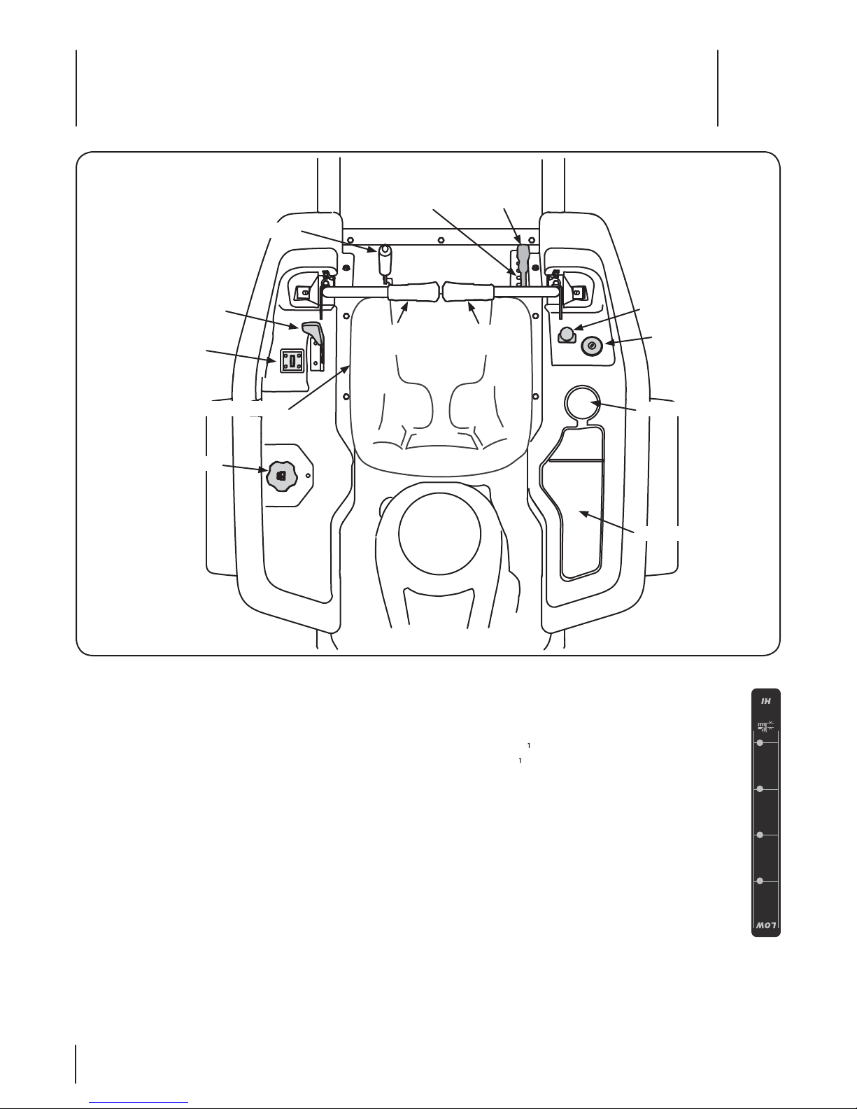
Parking Brake
Deck Height
Index
Deck Lift
Handle
RH Drive
Control Lever
LH Drive
Control Lever
Seat Adjustment Lever
Hour Meter/
Indicator Panel
Fuel Tank Cap
Ignition Switch
PTO Switch
Throttle/Choke
Control
Cup Holder
Storage Tray
Controls and Features
4
NOTE: This Operator’s Manual covers several models. Tractor
features may vary by model. Not all features in this manual are
applicable to all tractor models and the tractor depicted may
dier from yours.
NOTE: References to LEFT, RIGHT, FRONT, and REAR indicate that
position on the tractor when facing forward while seated in the
operator’s seat.
RH and LH Drive Control Levers
The RH and LH control levers are located on each side of the
operator’s seat. These hinged levers pivot outward to open
space to permit the
dismount the tractor. The levers must be fully opened out and in
the neutral position to start the tractor engine.
Each lever controls the respective RH or LH transmission.
Consequently, these levers control all of the movements of the
tractor. Driving and steering utilizing these control levers is
quite dierent from conventional tractors, and will take some
practice to master. Refer to Operation for instructions on using
the control levers.
operator to either sit in the tractor seat, or to
Figure 4-1
Deck Height Index
The deck height index consists of six index notches located
on the front/right of the seat box frame. Each notch
corresponds to a ⁄2” change in the deck height position
ranging from 1notch.
⁄2” at the lowest notch to 4” at the highest
Deck Lift Handle
The deck lift handle is located on the front/right of the seat
box frame, and is used to raise and lower the mower deck.
Pull the handle to the left out of the index notch and push
downward to lower the deck, or pull upward to raise the
deck. When the desired height is attained, move the lift
handle to the right until fully in the index notch.
HEIGHT
CUTTING
12
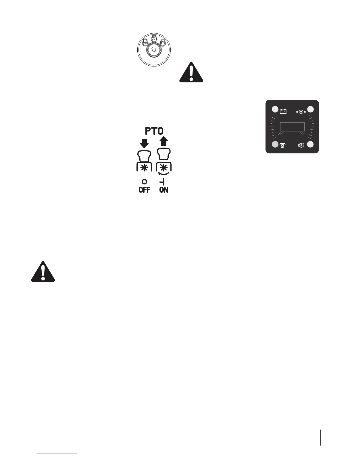
Ignition Switch
The ignition switch is located on the RH console
to the right of the operator’s seat. The ignition
switch has three positions as follows:
OFF - The engine and electrical system is
turned off.
ON - The tractor electrical system is energized.
START - The starter motor will turn over the engine. Release the
key immediately when the engine starts
NOTE: To prevent accidental starting and/or battery discharge,
remove the key from the ignition switch when the tractor is not
in use.
Power Take-Off (PTO) Switch
The PTO switch is located on the RH console to
the right of the operator’s seat.
The PTO switch operates the electric PTO
clutch mounted on the bottom of the engine
crankshaft. Pull the switch knob upward to
engage the PTO clutch, or push the knob
downward to disengage the clutch.
The PTO switch must be in the “disengaged”
position when starting the engine.
Transmission Bypass Rods (Not Visible)
The transmission bypass rods (one for each the RH and LH
transmission) are located beneath the frame platform, just inside
each rear wheel.
When engaged, the two rods open a bypass within the
hydrostatic transmissions, which allows the tractor to be pushed
short distances by hand. Refer to Maintenance & Adjustments for
instructions on using the bypass feature.
$"65*0/Never tow your tractor. Towing the
tractor with the rear wheels on the ground may
cause severe damage to the transmissions.
Do not attempt to remove the cap from the tractor.
Push the cap downward on the fuel tank fill neck and turn
approximately ⁄ turn clockwise to tighten Always re-install the
fuel cap tightly onto the fuel tank after removing.
8"3/*/(Never fill the fuel tank when the engine
is running. If the engine is hot from recently running,
allow to cool for several minutes before refueling.
Highly flammable gasoline could splash onto the
engine and cause a fire.
Hour Meter/Indicator Panel
L
I
HOURS 1/10
/
E
D
O
K
R
PA
E
K
A
R
B
The hour meter/indicator panel is
BATT.
located on the LH console to the left of
the operator’s seat.
Hour Meter Features
The hour meter records the hours that
the tractor has been operated in the
digital display (tenths of an hour - right
most digit).
NOTE: The hour meter is activated whenever the ignition switch
is turned to the “ON” position. Keep a record of the actual hours
of operation to assure all maintenance procedures are completed
according to the instructions in this manual and the engine
manual.
When key is turned to the “ON” position, the battery indicator
light briefly illuminates and the battery voltage is briefly
displayed. The display then changes to the accumulated hours.
The Indicator Monitor will also remind the operator of
maintenance intervals for changing the engine oil. The LCD
will alternately flash, “CHG” ; “OIL” and the recorded hours for
five minutes after every 50 hours of recorded operation. The
maintenance interval lasts for two hours (from 50-52, 100-102,
150-152, etc.). The LCD will flash as described for five minutes
every time the tractor’s engine is started during this maintenance
interval. Follow the oil change intervals provided in the engine
manual.
PTO
A
L
B
Cup Holder
The cup holder is located toward the rear of the RH console to
the right of the operator’s seat.
Storage Tray
The storage tray is located at the rear of the RH console.
Seat Adjustment Lever (Not Seen)
The seat adjustment lever is located below the front/left of the
seat. The lever allows for adjustment of the fore to aft position
of the operator’s seat. Refer to Maintenance & Adjustments for
instructions on adjusting the seat position.
Fuel Tank Cap
The fuel tank cap is located near the middle of the LH console.
Turn the fill cap approximately ⁄ turn and pull upward to
remove. The fuel cap is tethered to the tractor to prevent its loss.
SECTION 4 — CONTROLS AND FEATURES
 Loading...