

Columbia Records 560 Schematic
UI
ct
d,<
o
Hg
E'
==
o
TJ
PHoToFACT*
Fold.t
COTUMBIA
,VIODEL
RECORDS
560,
A
fl
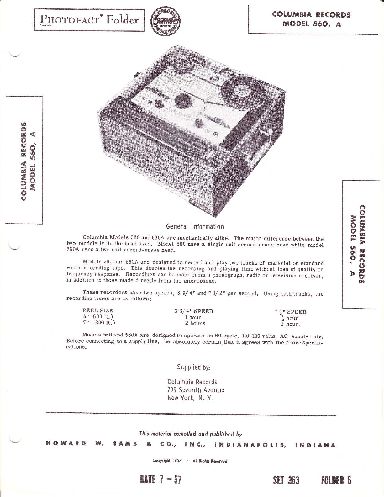
Columbia
two
models is
560A
uses a
Models
width
recording
frequency
in addition
These recorders
recording
REEL SIZE
(600
5"
(1200
?"
Models
Before
cations.
connecting
Models
in
the head
two
unit record-erase
560 and
tape.
response.
to those
times are as
ft.
ft.
560
)
)
and
made
to a supply
and
560
used.
560A are
This
Recordings
doubles
directly
have
two
follows:
560A are
line,
General
are
560A
Model
head.
designed
the
can
be made
from
speeds,
designed
be
Columbia
799
New
lnformation
mechanically
560
uses
a
to record
recording
and
from
microphone.
the
3
3/ 4n and
3 31
4" SPEED
I
hour
2
hours
to
operate
absolutely
Supplied
Seventh Avenue
York,
on 60
certain.
by:
Records
N. Y.
alike.
single
unit
play
two
playing
and
phonograph,
a
per
? l/ 2',
cycle, ll0-120
that it
The major
record-erase
tracks
second.
of material
time without
radio
agrees
with
difference
head
loss
between
while
on
of
or television
Using
both tracks,
?
sPEED
|',
hour
I
I
'houro
volts, AC
supply
the above
model
standard
quality
receiver,
only"
specifi-
the
or
the
3P
FF
.s3
>g
UI
HOWATD
rw.
sAts
ffris
moferiol
& co,,
Copyriglrt
compiled
lNC.,
.
1957
ond
Ail
Rightt Rcocrvcd
published
by
INDIANAPOlIS,
$t'I 363
INDIANA
FOTDTR
O

Figure
I
Fast
Forward
5" Reel,
7" Reel,.
Frequency
3 3/
7 L/ 2" speed
Bias
and
Bias
Voltage:
Shure
Michicgan
Power
Inputs:
Outputs:
Output:
2
Watts undistorted
3 Watts maximum
Microphone,
Radio-Phone,
Two internal
External
External-low
coil
External
or monitor
Maximum
?"
And Fast
(600
(1200
Response:
speed
4"
Erase
Frequency:
Head,
Mag.
3.2
for
external speaker.
high impedance
in
Reel Size:
(1200
ft.
)
Specifications
ft.
ft.
-
-
l0
Re$/ind
)
)
65
65
volts
Head,
to 6000
8500
to
bias
20
Speed
l5
105
cycles
cycles
bZ.
volts
I meg. impedance
meg.
.5
speakers
5"
ohm
impedance
impedance
speaker
across
for external
Record
or Playback
:
per
per
KC
bias
(Approx.
(Approx.
second
second
seconds
seconds
b
3.2 ohm voice
amplifier
position.
Speed
)
)
The
placing
or
'Down"
'Down"
CAUTION: NEVER
the ON-OFF switch
Threading Tape
l. Place
(9),
and an empty
certain the reel slots
2.
center of
position.
3.
a
section
the tape in
coated side
4. Insertthe
radial slots
several
the reel and
To Record
control to the right.
tubes to warm
2. Insert
iack"
3.
speed - 3 3/ 4"
sired
4. Push down on the Play-Record
Control
operating
the speed
position.
for 7 l/ 2"
Turn
the machine
Unwind
of the
the tape slot
faces
in hub
turns,
all slack
From
Adjusi
speed setting
control
"IJp"
pet
a reel
reel
engage
ng
I nstructions
button
for 3 3/ 4"
second.
operate
(12)
of tape
on
the
thepins
Operati
the H.ay-Record
to the fully
about
I0"
tape straight
the
end
of the
clockwise,
Microphone
up.
the microphone
the
of
making
rear
of the recorder"
ofthe
tape-up
until
is
taken
Allow
speed
control
7 l/ 2"
or
with
about
is
accomplished
(I)
in
either the
per
this control unless
is in
the
ON
on the right
left
tape
tape intooneof
up
nby
plate
reel
on the reel
control
the
knob
counterclock-wise
from
the reel" Hold
both hands and
certain
reel.
between the reels.
that the dull
Turn
tape is secured
rotating the
30 seconds
plug
into
(1)
knob
per
second.
control
ilUpil
second and
position.
plate
reel
(9)
making
plates.
(b)
in
the
insert
thethree
the
reel
"Tone,,
for
the
the
"Mike"
for
the de-
knob
by
to
Page
2
(5)
as faras it willgo. Hold knobdownand
wise until it locks"
about
NOT
cord level
tb 12 inches and
6
SHOUT.
indicator flashes
Hold
5.
Note:
important.
flashing
in weak
a
indicator,
To
these
1.
speaker:
the radio speaker.
a normal
Turn
recording
Microphone".
2.
phone
other end.
coil terminals
into
and
level
Microphone".
on the recording level indicator,
playback
signal,
which
will result in distortion during
Record From Radio:
Recordings
methods.
Through
Place
level.
the radio
level andrecord
Though
Make up a shielded
plug
Connect
the
"Radio-Phono"
tone
controls
proceed
and
3. Through a
of the radio:
Make up
phone
plug
the radio
"Radio-Phono"
ceed as
The
set
up,
on one
volume control.
described under
radio
volume
consequently they may be set
microphone
the
Adjust
the volume control until the re-
away
speat in a normal
on the
Correctvolumelevelonrecording isvery
Too weak a signal,
and high
causes continuous flashingof the
background noise. Too strong
from
a radio may
the microphone
the microphone about
a
direct
Turn the radio
Setting it
tone control to
too
connection
which
pickup
by
high
will cause
treble or
as under
to the Radio speaker;
cable with a
on one end and two alligator
alligator
the
of the radio speaker and
jack.
as
described above.
as
described
clips
Set
under
direct connection to the volume
a shielded
end.
Connect the other
jack.
Set the
"To
and tone controls do not alfect this
with a
cable
Insert
the
recording level andpro-
Record from Microphonetl
turnclock-
your
from
mouth
voice. DO
loudest
does
sounds.
not
cause
will result
playback.
be made by one of
from the radio
12"
6" to
volume control to
"ToRecord
across
the
Set the recording
I'To
phoneplug
any
front
in
distortion.
high. Set
From
two conductor
clips on
the voice
insert the
radio volume
end
place.
From
control
across
in the
Record
two conductor
level
the
the
plug
1
head cover. This wiU
reel at a high speed aslong
position.
NOTE: Do
operation with
except neutral
of
tape will
t}te
the Play-Record
position,
result.
Braling
This recorder contains an automatic
giving
anism
at
tape
fast rewind,
control. The
1o Play
1.
ing Tape".
2. Turn
of
out depressing
3. Adjust
desired listening level.
to
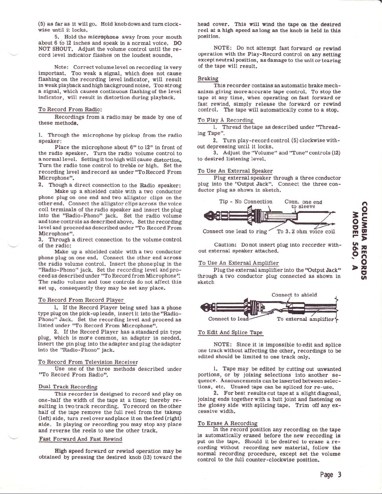
To Use
Plug external speaker
plug
into
ductor
moreaccurate
any time,
simply
tape will automatically
A
Recording
Thread the tape
play-recordcontrol
until it locks"
the
An External
the
"Output
plug
as shown
Tip
No Conuection
-
wind the tape
as the knob
not
attempt
when operating on fast forward or
release
"Volurne"
Speaker
fast forward
as damage
tape control. To
the
as described
and'ofonet'controls
through
Jack". Connect
on the desired
control
to the unit
forward
come
under
(5)
clockwisewith-
a
three conductor
is held in
on any setting
brake mech-
this
rewind
or
or tearing
stop the
rewind
or
a stop.
to
rThread-
(12)
the three con-
in sketch.
Conn.
one
end
..l
=P
Connect
out external
To
through
sketch
one lead
to ring
Caution: Donot
speaker attached.
An External Amplifier
Use
Plug
external amplifier
the
a
two
conductor
insert
plug
3.2 ohm
To
plug
into recorder with-
into the
connected as shown in
[Output
Jackfl
9;
F>-
tt
q*
.-fl
>-
o
E'
l,l
To
Regorl From Record Player
1"
If
plug
type
Phono"
listed
plug,
Insert the
into
the
To
Record From Television
"To
Dual
the Record Player being used has a
pick-up
on the
Jack. Set
under
"To
2. If
the Record Player has astandard
which is mor'e
pin
plug
"Radio-Phono"
Use one of
Record From
Track
Recording
Leads,
the recording level and
Record From
common,
into the adapter and
the three methods
Radio".
insert it into
Microphone'r.
an
jack.
Receiver
This recorderis designed to record and
one-half the width of the tape
sulting
half
(left)
side.
and
Fast
obtained
in twotrack
of the
tape
side,
turn reeloverandplace
playing
In
reverse the reels to use the other track.
Forward And Fast
High speed forward
pressing
by
recording. Torecord
remove
or recording
the
at a
full reel from the takeup
the
you
Rewind
rewind
or
degired knob
phone
I'Radio-
the
proceed
pin
adapter is needed.
plug
described under
the
type
adapter
play
time; thereby re-
on theother
iton
thefeed(right)
may stop any
operation
(13)
place
may
toward the
as
on
be
And
to
Splice
Connect
To Edit
NOTE: Since
trackwithout
one
should
edited
1. Tape
portions,
quence.
tions, etc.
2.
joining
glossy
the
cessive
In
be
may
or by
Announcements
Unused
For
best results
ends
togetherwith a
side
width.
the record
with
is automatically
put
on the tape.
cording
normal recording
control to the full
without
Tape
it is impossible
affecting
limited
joining
position
erased
Should it be desired
recording new
procedure,
counter-clockwise
the other, recordings to
to one track only.
be edited
by
cutting
selections into another
can
inserted
cut tape
splicing
be
spliced
be
at a slight
joint
butt
tape. Trim off
any recording
tape can
before the new recording is
material, follow the
except set the
and
toedit
out unwanted
between
selec-
for re-use.
and fastening
position.
diagonal,
any
on the tape
to erase a re-
volume
Page
splice
be
se-
on
ex-
3
Spindle
up and
(65)
up
obtained.
Take-Up
timingof
trol
shouldstart
the Pressure
the head
(19
and
48)
The
spindles should
down movement.
on spindle
or
down as required
to
Lever Adjustment
the
(5)
(83)
left
in the
Spring
knob
revolvingat
Roller
(39).
be
on take-up lever
take-up
Check adjustment
reel
on
conds.
position
arm
sketch
making
bends
Take-Up
tral"
minimum
tape.
without
butonce
the take-up spindle.
Move the control
and
observe
If
adjustment is required,
(85)
iu
on exposed
this
should be
And
When
position
With
reels
the
position
the
adjustment
made.
Feed
the
control knob
the reels
of overrun.
control knob
on theholders,
reels are
volve.
Stops, labeled
(22)
on base
gulate
rewind
leasedl
Fast
much
put
carefully so
Stop
trols
Head Alignment
lined
probably
plate
the amount
arm
controls the above action.
of return that
(52)
makes after
not sufficient return
Rewind or Fast Forward
return
a
drag
"C"controls
the rewind side.
up
would not allow
respective
on the
as
to obtain operation
the take-up sidewhile
Adjustment
is
It
extremely important
perfectly
be
low
with
output,
frequencies.
l.
Model
If
complete
holder
individuallvto
installing
HEAD
11/64"
and
plate (22)
base
on head
gauge.
An
when a
(SHURE
560
the SHURE
assembly composed
should
be replaced"
thehead
(
39A)
head
HEIGITT:
3/16") near the mounting
and
(39A)
and
alternate method
gauge
is not available follows:
Adjustments
End Play Adjustment
have from
To adjust loosen
adjusted
andmove
until the
reelholder
play
(43)
back
the
starts
by
position,
sametime
placing
Rewind
knob
action
the
and direction
view.
Caremustbeexercised
and repeated
Reel Drag
(5)
should
Thereshould
(5)
in
the neutral
they mayrevolve slightly,
put
place
in
and
"C"
'T)"
l/ 32,, to l/16'rof
set screw
pulley (bb)
the
correct end
(90)
controls the
(9).
Withthe
thetake-up reel
pulling
the
tape
littleafter
ora
a fully loaded
for about
(5)
to the
described above.
bend ear
playback
on take-up
indicated
trials between
placed
is
stop
on figure 2, located
in
the
prompuy
benoloopingof
position
they should
Theyre-
take-up arm
controls have
would
cause continued
been re-
operation, while
drive
pulleys.
that
the tape. If not
track overlap,
Head)
(88)
belts
Bend these
described
stop
the Head
the result will
loss
or
or
tDrtcon-
Head requires replacement
of the head
The head holder is adjusted
and sealedatthefactory.
observe the following
Place a
bottom of head holder. Push
tighten set screw
.l?9"
bracket
ofadjusting
and
precautions:
gauge (between
and between
(23).
Remove
the head
play
con-
past
10 se-
when
INeu_
with
and
not
re-
(85)
too
(59)
stops
above.
(39)
of high
the
head
When
down
height
?',
in
the
or
to
be
a).
Remove the
from
the
observed through
be
sure
bracket"
Align
b).
opening is at
as
er)
is
ing of the
c).
With the unit
approach
between
runs against
dication
d).
Make
scribed in Section 3
2"
Model 56OA /Michionn Mrqnctin F{cad\
On units using
simpl.e
alignment
a). Place a full
spindle(19)
TaPe".
b). Pull tape tightagainst Heads
rotating
c). Both heads should
edge
top
bottom
on the face
d).
When
perpendicular
be
and
horizontally.
e). The faces
a
3.
cycle
good
aeross the spealer
While
(39)
mum amplitude
certain that head
cording with hlgh
each
the tape, i.
further forward
Output
Besponse
To make
note
has
operating
Connect
playingback
and forth
back
If a
3000
other soas
this adjustment
been recorded
condition
an
cycle tape
pressure
pressure
shoe assembly
bracket
so
the head can
theopeningin
(39A)
head
the correspondingbottom
pressure
the take-up reel nearly centered
the flanges
that the head
"Output
procedure
so the
bottom of
same level
the
(or
slightly high-
bracket.
pulling
the bottom
Response"
the
tape, the tape
reel. If
of the
flange it
is
too low.
adjustment as
below.
Michigan Magnetic Head
is as follows:
of the open-
reel of tape on the right
andthread tape. See
reel while holding
one
of the tape
edge of the
then be
is exactly even
ground
of the heads.
in
thisposition
to
of
heads
the
present
to
e.
output meter,
voice
the 3000cyclenote
on mounting
on
output meter
height
note
head should
one
than the
by
will
be
coil of theunittobe adjusted.
has not
cannot
content
to make
down
both
the
bracket vertically
should
other"
a
tape on which a 3000
a
unit known
required.
or
screw
is achieved.
been changed.
be make,
"Threading
(26)
the other
positioned
'tlat"
heads shouldalso
j.n
be
a flatsurface
not
AC
tape,
(23)
until maxi-
the adjustment
(36)
thepres-
the head
should
the tape
an in-
is
de-
hand
and(28)
reel.
so
the
with the
section
line with
protrude
to
be
voltmeter,
pivot
head
Make
a
use
re-
a
by
to
in
described above.
Track
4.
cording on a
and
isbackwards,
it
will be necessary
of the
move the tracks further
Switch Cam Adjustment
is normally held inthe
on
the
shaft
far enough
Playback to Record.
Overlap
This should
Do notrewind
play
There should
The Play-Record
(70)
blank tape
back
the other
there is trackoverlap.
head
holder
switch arm.
actuates
to allow all
be checked
with the unit
thetape,
by first making
being
merelyreverse
track.
no
be
sound
but, if what is
to adjust
by
bending it upwards.
the tape
apart.
Switchin
the amplifier
playpositionby
Whencam onthe endof
switch,
it should
circuits
to be
a re-
checked.
thereels
Tocorrect this,
heard
guide
on the side
This should
aspringlocated
chassis
thecontrol
move the switch
switched
from
Page
4
 Loading...