

Columbia MPH SERIES, MPH 30, MPH 40, MPH 50, MPH 60 Installation, Operation And Maintenance Manual
...
COLUMBIA
MULTI-PASS HORIZONTAL BOILER
MPH SERIES
INSTALLATION,
OPERATION and
MAINTENANCE MANUAL
COLUMBIA BOILER COMPANY
POTTSTOWN, PENNSYLVANIA


Table Of Contents
PARTS WARRANTY . . . . . . . . . . . . . . . . . . . . . . . . . . . . . . . . . . . . . . . . . . . . . . . . . . . . . . . . .2
INTRODUCTION . . . . . . . . . . . . . . . . . . . . . . . . . . . . . . . . . . . . . . . . . . . . . . . . . . . . . . . . . . . .3
SERVICE POLICY . . . . . . . . . . . . . . . . . . . . . . . . . . . . . . . . . . . . . . . . . . . . . . . . . . . . . . . . . . .4
INSTALLATION . . . . . . . . . . . . . . . . . . . . . . . . . . . . . . . . . . . . . . . . . . . . . . . . . . . . . . . . . . . . .5
BOILER ROOM . . . . . . . . . . . . . . . . . . . . . . . . . . . . . . . . . . . . . . . . . . . . . . . . . . . . . . . . . .5
VENTING . . . . . . . . . . . . . . . . . . . . . . . . . . . . . . . . . . . . . . . . . . . . . . . . . . . . . . . . . . . . . . .5
JACKET ASSEMBLY . . . . . . . . . . . . . . . . . . . . . . . . . . . . . . . . . . . . . . . . . . . . . . . . . . . . .6
BURNER MOUNTING . . . . . . . . . . . . . . . . . . . . . . . . . . . . . . . . . . . . . . . . . . . . . . . . . . . . .6
BOILER CONNECTIONS . . . . . . . . . . . . . . . . . . . . . . . . . . . . . . . . . . . . . . . . . . . . . . . . . .7
FUEL CONNECTIONS . . . . . . . . . . . . . . . . . . . . . . . . . . . . . . . . . . . . . . . . . . . . . . . . . . . .9
CLEANING AND FILLING A NEW STEAM BOILER . . . . . . . . . . . . . . . . . . . . . . . . . . . . . . .14
OPERATING THE BOILER . . . . . . . . . . . . . . . . . . . . . . . . . . . . . . . . . . . . . . . . . . . . . . . . . . .16
STARTING THE BOILER . . . . . . . . . . . . . . . . . . . . . . . . . . . . . . . . . . . . . . . . . . . . . . . . .17
STOPPING THE BOILER . . . . . . . . . . . . . . . . . . . . . . . . . . . . . . . . . . . . . . . . . . . . . . . . .17
BURNER START UP AND TEST INFORMATION . . . . . . . . . . . . . . . . . . . . . . . . . . . . . .18
CONTROL DESCRIPTIONS . . . . . . . . . . . . . . . . . . . . . . . . . . . . . . . . . . . . . . . . . . . . . . .19
MAINTENANCE . . . . . . . . . . . . . . . . . . . . . . . . . . . . . . . . . . . . . . . . . . . . . . . . . . . . . . . . . . .22
Daily Boiler Check & Maintenance List . . . . . . . . . . . . . . . . . . . . . . . . . . . . . . . . . . . . .22
Weekly Boiler Check & Maintenance List . . . . . . . . . . . . . . . . . . . . . . . . . . . . . . . . . . .22
Monthly Boiler Check & Maintenance List . . . . . . . . . . . . . . . . . . . . . . . . . . . . . . . . . .23
Semiannual Boiler Check & Maintenance List . . . . . . . . . . . . . . . . . . . . . . . . . . . . . . .23
Annual Boiler Check & Maintenance List . . . . . . . . . . . . . . . . . . . . . . . . . . . . . . . . . . .23
WATER TREATMENT . . . . . . . . . . . . . . . . . . . . . . . . . . . . . . . . . . . . . . . . . . . . . . . . . . . . . .25
MPH COLUMBIA BOILER COMPANY
1
IMPORTANT
1. Read and familiarize yourself with this installation, operation, and mainte
nance manual before installing, operating, or servicing your boiler.
2. All cover plates, enclosures, and safety devices must be installed at all
times except while performing maintenance and service.
3. Only trained service technicians should do any work on your boiler.
4. All state and local codes take precedence over any recommendations given
in this manual.
5. Columbia Boiler performed testing on the MPH boiler line using specific
makes and models of burners. Should you choose to supply your own burner, please contact the burner manufacturer to confirm compatibility with the
MPH boiler design.
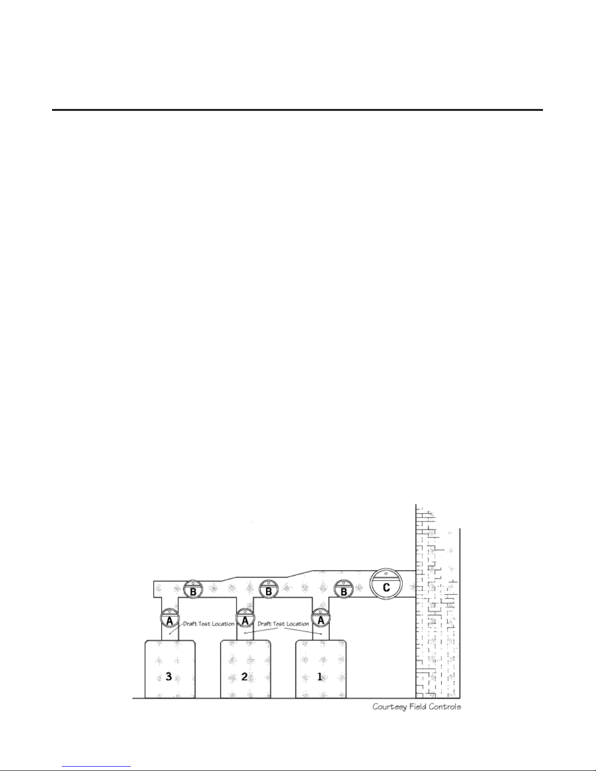
6. A barometric damper or draft regulator may be required on MPH installations. A draft regulating device is required on all multiple boiler installations
where the boilers utilize common breaching. One regulator is required per
boiler. Regulators can be installed in each individual boiler breach (Location
A) or in the common breach, just upstream of each connection between the
boiler breach and the common breach. (Location B) One regulator (Location
C) is not acceptable.

MPH COLUMBIA BOILER COMPANY
2
LIMITED PARTS WARRANTY
The Columbia Boiler Company (hereinafter Columbia) warrants the burner components
and controls installed on its boiler/burner units to be free from defects in material and workmanship under normal use and service for 12 months from the date of installation or 18
months from the date of manufacture, whichever date occurs first, and is subject to warranty
approval by the manufacturer of the specific components. This warranty does not extend to
equipment subjected to misuse, neglect, accident or improper installation. Equipment which
is defective in material or workmanship and is removed within 12 months from the date of
installation will be repaired or replaced as follows:
a. Motors, fuel units, controls, and transformers should be sent for repair or replacement
to an authorized service point or distributor of the manufacturer of such component
when reasonably available in Customer’s locality.
b. Where such local service is not available with respect to the above listed components, or
where other components are involved, such defective equipment should be returned after
receiving authorization from your dealer, freight prepaid, to the Columbia Boiler Co.,
390 Old Reading Pike, Pottstown PA 19464. The use of the Columbia returned goods
form is mandatory when returning defective material.
c. Columbia is not responsible for any labor cost for the removal and replacement of
equipment.
d. Equipment which is repaired or replaced will carry a warranty equal to the unexpired
portion of the original equipment warranty.
e. If inspection by Columbia does not disclose any defect covered by this warranty, the
equipment will be repaired or replaced at the expense of the Customer, and Columbia’s
regular charges will apply.
THIS WARRANTY IS LIMITED TO THE PRECISE TERMS SET FORTH ABOVE,
AND PROVIDES EXCLUSIVE REMEDIES EXPRESSLY IN LIEU OF ALL OTHER
REMEDIES. ALL IMPLIED WARRANTIES, INCLUDING BUT NOT LIMITED TO
ANY IMPLIED WARRANTY OF MERCHANTABILITY OR FITNESS FOR A PARTICULAR PURPOSE OR USE,ARE EXCLUDED. IN NO EVENT WILL COLUMBIA
BOILER CO. BE LIABLE FOR ANY INCIDENTAL OR CONSEQUENTIAL DAMAGES OF ANY NATURE. Columbia neither assumes nor authorizes any person to assume
for Columbia any other liability or obligation in connection with the sale of this equipment.
Columbia’s liability and Customer’s exclusive remedy being limited to repairs or replacement
as set forth above.
March 10, 1997

MPH COLUMBIA BOILER COMPANY
3
INTRODUCTION
Series MPH Modified Scotch Boiler
The Columbia Multi-Pass Horizontal (MPH) boiler is a modified scotch boiler
designed for hot water, and/or low pressure steam applications. The pressure vessel
is available as a welded pipe boiler or a rolled tube boiler. These units are manufactured to the specifications set forth by Section IV of the ASME Boiler and Pressure
Vessel Code. Boilers are inspected and stamped for conformity to requirements of
the National Board of Boiler and Pressure Vessel Inspectors. All boilers are designed
to be fired using No. 2 fuel oil, and/or natural, manufactured, or liquid propane (LP)
gas, and are powered by standard AC electrical service.
Columbia MPH hot water and low pressure steam boilers are typically shipped
knocked down (unassembled), but are also available factory packaged. All boilers are
furnished with a burner and boiler trim (the jacket is factory installed). Boiler trim consists of the operating and limit controls, pump control and/or low water cut off
(LWCO) controls, and a safety valve. Factory packaged boilers are fully assembled
and test fired.

MPH COLUMBIA BOILER COMPANY
4
SERVICE POLICY
Steam and hot water boilers are routinely serviced by the installer or another boiler
maintenance company. Occasionally the service technician may be unable to determine the cause of the problem. In this situation, the dealer or service organization
should contact the selling distributor for help.
Should the problem persist, the distributor will contact the sales representative for
assistance. Depending on the extent of the problem, the representative may request
technical assistance from the factory.
If the problem cannot be resolved by the representative, the representative or serviceman should contact the Technical Service/Engineering Department at the factory.
The following information will be needed. It is essential that this information be available to assure prompt service.
Boiler Model and Size (HP) _____________________________________________
Boiler Serial Number __________________________________________________
Boiler National Board Number ___________________________________________
Date Installed _______________________________________________________
Burner Type and Model ________________________________________________
Primary Burner Control Type ____________________________________________
Installer's Name ______________________________ Phone (___)____________
Address ____________________________________________________________
Distributors Name ____________________________ Phone (___)_____________
Address ____________________________________________________________
Sales Representative __________________________ Phone (___)_____________
Address ____________________________________________________________
Specific Problem - Detailed

MPH COLUMBIA BOILER COMPANY
5
INSTALLATION
BEFORE BEGINNING INSTALLATION, CAREFULLY STUDY THESE
INSTRUCTIONS AND ALL CHARTS, DRAWINGS, AND DIAGRAMS
SHIPPED WITH THE BOILER
.
Installation must follow all state and local code requirements, Fire and Underwriters regulations,
and standard plumbing practices. The electrical installation shall be in accordance with the
National Electrical Code.
Remove all boiler components from packaging and inspect prior to assembly to ensure that
damage has not occurred in shipping.
BOILER ROOM
Locate the boiler in a well lit area on a noncombustible, level floor. Make available a convenient
water supply and allow adequate drainage, including unobstructed floor drains, for flushing and
filling the boiler. Provide sufficient make-up air for combustion at all times. See section on “Combustion Air” later in this manual. Power the boiler using a properly rated electrical service.
Include fused disconnects for control circuits, blower motor circuits, and feed pump circuits that
require a motor contactor or motor starter relay.
Where possible, place the boiler on a 3 inch concrete pad. Allow adequate clearance between
the boiler and any walls or obstructions to permit inspection and service on burner, boiler piping, controls, or combustion vent.
DO NOT install exhaust fans in or near the boiler room. Exhaust fans consume available makeup air during burner operation. More importantly, when the boiler cycles off, exhaust fans pull
hot flue gases back through the burner causing burner parts to deteriorate, and possibly fail.
Maintain a positive pressure in the boiler room at all times. Refer to the combustion air section
of this manual for additional information.
Do not allow your boiler room to become a storage room.
VENTING
Locate the boiler as close as possible to the chimney or other approved exhaust vent. Attach all
flue piping to the round flue connection and make each connection secure. The flue pipe should
not be inserted beyond the inside wall of the chimney.
DO NOT REDUCE THE SIZE OF THE FLUE OUTLET OR FLUE PIPING.
Columbia Boiler recommends the use of galvanized “B” Type vent for stack connections suitable for temperatures to 550F. The flue pipe should be pitched upward at least 1/4" per foot of
run. Avoid the use of tees, sharp bends, and long horizontal runs. Install a draft regulator if
required. See page 4 for draft regulator installation on multiple boilers with common breaching.
All Columbia boiler models utilize a pressure fired burner and need only to be properly vented.
For situations where unusual conditions may exist, consult the factory for proper venting.
MPH COLUMBIA BOILER COMPANY
6
COLUMBIA BOILER COMPANY OF POTTSTOWN SHALL NOT BE HELD LIABLE FOR
DAMAGE TO THE BOILER CAUSED BY INCORRECT VENT CONDITIONS AND/OR
INSUFFICIENT BURNER MAKEUP AIR.
JACKET ASSEMBLY
The jacket for the MPH boiler is factory installed and should not have to be removed for installation of the boiler.
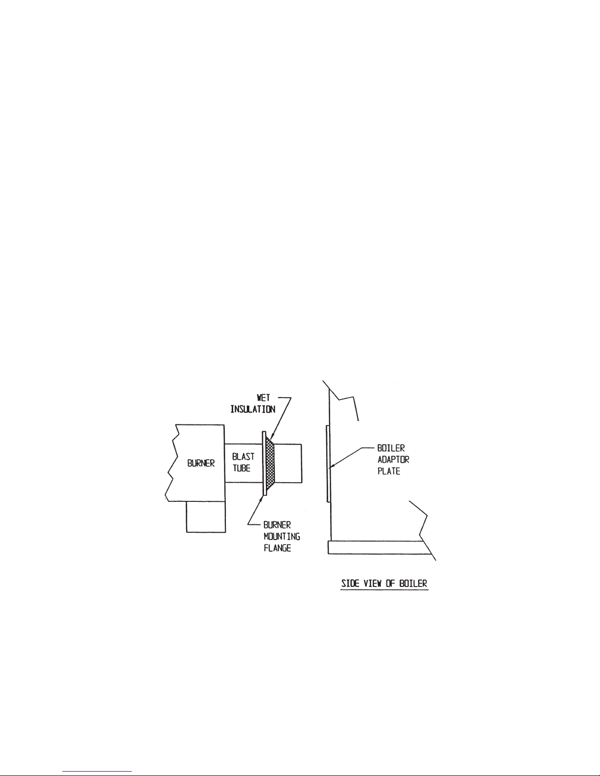
BURNER MOUNTING
If the burner is to be installed on site, first apply a gasketing material between the burner flange
and the burner mounting plate to seal the burner. Use a non-asbestos fiber rope, or a wet insulating material for a gasket, as shown in Figure 2. Wet insulation is the preferred gasketing
material because it compresses into a flat gasket which conforms to and fills any and all voids.
Secure the burner in the boiler using the four bolts supplied with the burner. See the Burner Section of this manual for proper electrical wiring, and fuel supply piping.
Note: All factory packaged boilers use a wet insulation material as a gasket.
Figure 1

MPH COLUMBIA BOILER COMPANY
7
BOILER CONNECTIONS
Drains
All Columbia Boiler MPH units have (2) 1-1/4" drains. These are located in the front and rear of
the boiler below the fire chamber. Install a pipe nipple and ball valve in a least one for use as a
drain. If a drain is not needed, plug it by using the proper size nipple and a pipe cap. DO NOT
use a pipe plug.
Low Water Cut-Offs
All Columbia boilers are supplied with at least one low water cut-off (LWCO) as standard equipment. Some boiler applications may require a secondary LWCO. The standard equipment is as
follows:
Hot Water Boilers - McDonnell & Miller 750-MT-120 Probe Type Low Water Cut-Off with
Remote Sensor - Thread the Remote Sensor into the 3/4" NPT fitting located on top of the boiler. Mount the Control Box near the top of the side jacket panel.
Steam Boilers - McDonnell & Miller Model 157 Low Water Cut-Off/Pump Control - Install this
device into the 1" NPT welded couplings found on the top and either side of the boiler. Only two
of the three 1" NPT will be used. The 157 can be piped to either side of the boiler.
Secondary Low Water Cut-Offs
Secondary LWCO’s may be required to meet local codes or CSD-1 requirements. A Warrick
26C1D1C Probe Type Low Water Cut-Off is used in steam applications to meet CSD-1 requirements and is also standard on steam units. Thread the remote sensor into the 1/2” NPT fitting
located on top of the boiler using a 1/2” x 3/8" bushing. See Table 1. for proper probe rod length.
Mount the control box to a side jacket panel on the boiler.
LENGTH OF PROBE ROD IN “MPH” SERIES BOILERS
BOILER MODEL MPH MPH MPH MPH
30/40 50/60 70/80 90/100
ROD LENGTH 14" 14" 14" 12"
TABLE 1
Other secondary LWCO’s include combination LWCO / Water Feeders. These devices are typically connected externally using an equalizing line, and piped into the available 1" NPT fittings
found in boiler top, and left side or front. Most commonly used combination units are McDonnell
& Miller 42 Series Pump Controls and Low Water Cut-Off or McDonnell & Miller No. 247-2 Feeder Combination. For piping diagram, see the List of Figures on the Table of Contents Page of
this manual.
 Loading...