

Columbia MCB50, MCB75, MCB100, MCB125, MCB150 Installation, Operation & Maintenance Manual
...
MODEL NUMBERS:
MCB50 MCB75 MCB100
MCB125 MCB150 MCB175
MCB200 MCB250 MCB300
MCB SERIES
Cast Iron Gas Fired Boilers
For Forced Hot Water
INSTALLATION, OPERATION &
MAINTENANCE MANUAL
Columbia Company
Main ofces and Factory:
Pottstown, PA
P/N 37612101, Rev. E [05/2012]
H
INSTALLATION, OPERATION AND MAINTENANCE MANUAL
Ratings & Data - Natural Gas & Propane Gas ...........3
Dimensions .........................................................4
Installation Procedure ..........................................5
Ventilation & Combustion Air .................................6
Connecting Supply and Return Piping .....................7
Connecting Supply and Return Piping .....................8
Vent Installation ................................................ 12
Vent System Modication .................................... 12
Vent Damper Installation & Instructions ................ 13
Connecting Gas Service ...................................... 14
Electrical Section ............................................... 15
Wiring Diagram - 24V Standing Pilot .................... 16
Wiring Diagram - Intermittent Ignition ................. 17
Lighting Instructions .......................................... 18
Normal Sequence of Operation ............................ 20
General Instructions .......................................... 20
Checking Gas Input Rate To Boiler ....................... 22
KEEP THIS MANUAL NEAR BOILER
RETAIN FOR FUTURE REFERENCE
IMPORTANT: Read the following instructions
COMPLETELY before installing!!
WARNING
Keep boiler area clear and free from
combustible materials, gasoline and other
ammable vapors and liquids.
DO NOT obstruct air openings to the boiler
room.
Modication, substitution or elimination
of factory equipped, supplied or specied
components may result in property damage,
!
personal injury or the loss of life.
TO THE OWNER - Installation and service of
this boiler must be performed by a qualied
installer.
Replacement Parts - Base ................................... 23
Safety Symbols & Warnings
The following dened symbols are used throughout this
manual to notify the reader of potential hazards of varying
risk levels.
DANGER
Indicates a hazardous situation which, if
!
not avoided, WILL result in death or serious
injury.
WARNING
Indicates a hazardous situation which, if
!
not avoided, could result in death or serious
injury.
CAUTION
Indicates a hazardous situation which, if not
!
avoided, may result in minor or moderate
injury.
TO THE INSTALLER - Leave all instructions
with the boiler for future reference.
When this product is installed in the
Commonwealth of Massachusetts the
installation must be performed by a Licensed
Plumber or Licensed Gas Fitter.
WARNING
All installations of boilers and venting shall
be done only by a qualied expert and
in accordance with appropriate manual.
Installing or venting a boiler or any other gas
!
appliance with improper methods or materials
may result in serious injury or death due to
re or to asphyxiation from poisonous gases
such as carbon monoxide which is odorless
and invisible.
NOTICE
Indicates information which should be
followed to ensure proper installation and
operation.
C.S.A. Certied
For Natural Gas Or Propane
2
Tested For 100 psi.
ASME
Working Pressure
RATINGS & DATA - NATURAL GAS & PROPANE GAS
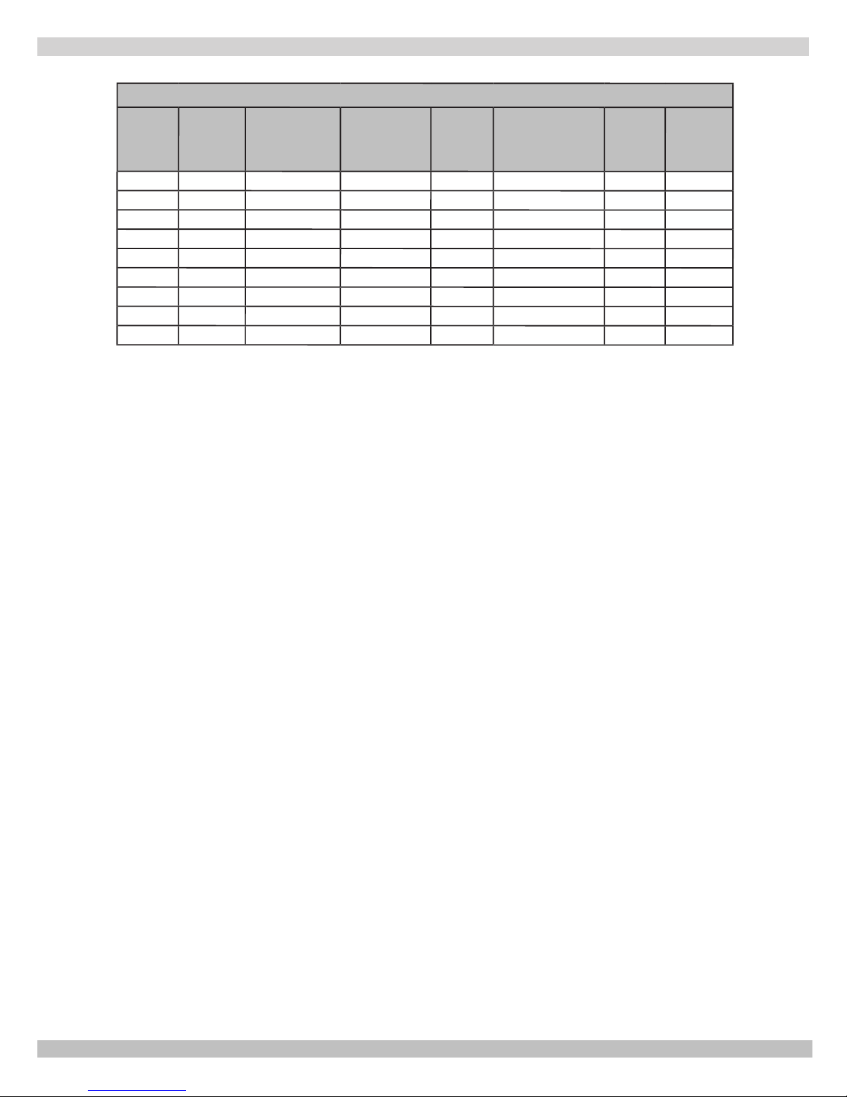
Table 1 - Ratings and Capacities
(2)
**
Net Rating
Water
Mbh
37
55
72
90
108
124
143
178
214
No.
of
Burners
1
2
2
3
3
4
4
5
6
Boiler
No.
50
75
100
125
150
175
200
250
300
(1)
Input
Mbh
50
75
100
125
150
175
200
250
299
(1)
Heating
Capacity Mbh
42
63
83
104
124
143
165
205
243
EXPLANATORY NOTES
-- All boilers are design certied for installation on noncombustible oor.
-- For installation on combustible oors use combustible oor kit.
(3)
Recommended
Air Cushion
Tank
15
15
30
30
30
30
30
30
60
Water
Content
(Gals.)
2.4
4.0
4.0
5.6
5.6
7.2
7.2
8.8
10.4
High
Altitude
Input
45,000
67,500
90,000
112,500
135,000
157,000
180,000
225,000
270,000
-- Recommended chimney height 20 feet. In special cases where conditions permit, chimney height may be
reduced to 10 feet. Refer to the latest revision of NFGC part 11.
-- Electric service to be 120 Volts, 15 Amps, 60 Hz.
-- The MEA number for the this boiler is 19-79-E.
(1) Input rating for sea level to 2,000 ft. (610m) above sea level.
• United States, over 2000 ft (610m) above sea level. Reduce input rate 4% for every 1000 ft (304m) above sea
level.
• Canada, 2000 ft (610m) to 4500 (1350m) above sea level. Reduce input per table.
• Canada, over 4500 ft (1350m) above sea level. Contact Provincial authority having jurisdiction.
(2) Net Water Ratings shown based on piping and pickup allowance of 1.15. Consult manufacturer before
selecting boiler for installations having unusual piping and pickup requirements, such as intermittent
system operation, extensive piping systems, etc.
For forced hot water systems where boiler and all piping within area to be heated, boiler may be selected
on basis of its heating capacity.
(3) Tank sized for non-ferrous baseboard or radiant panel systems. Increase size for cast iron baseboard and
radiation.
STANDARD EQUIPMENT: Boiler Jacket, Cast Iron Boiler Battery, High Limit Control, Vent Damper Relay,
Theraltimeter Gauge, Circulator With Return Piping To Boiler, Main Gas Burners, Combination 24 Volt Gas Control
(Includes Automatic Gas Valve, Gas Pressure Regulator, Automatic Pilot, Safety Shutoff, Pilot Flow Adjustment, Pilot
Filter), A.S.M.E. Relief Valve, Drain Valve, Spill Switch, Rollout Switch, Automatic Vent Damper. Not Shown Are:
Wiring Harness, Thermocouple, Non-linting Safety Pilot.
OPTIONAL EQUIPMENT: Intermittent Electric Ignition Pilot System.
3
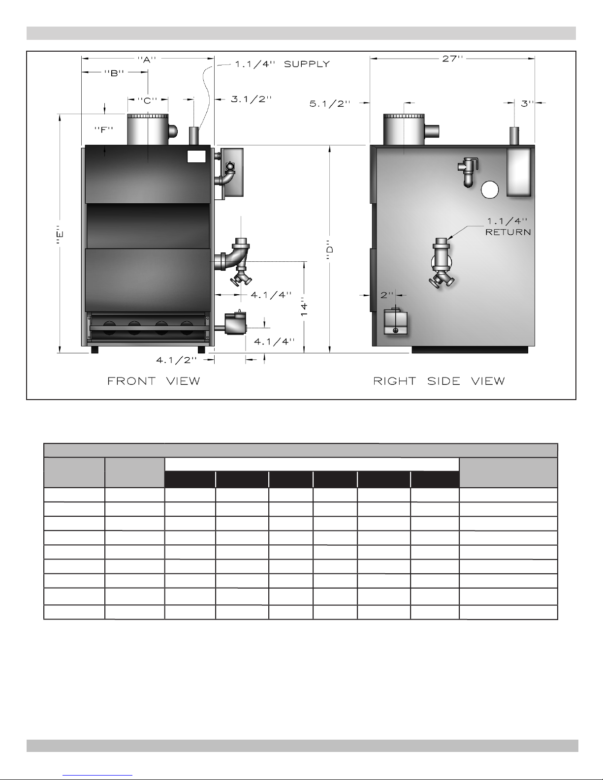
DIMENSIONS
Table 2 - Dimensions
Boiler No.
50
75
100
125
150
175
200
250
300
* Propane gas inlet, all units, 1/2"
Natural Gas
Inlet*
½"
½"
½"
½"
½"
½"
½"
¾"
¾"
26
A
11⅛"
15
15
18⅞"
18⅞"
22
¾
22
¾
13
30½"
Dimensions
B
5
½
"
7
½
"
7
½
"
9
½
"
9
½
"
"
"
⁄
"
16
11
½
11
½
13¼"
"
"
15¼"
4"
5"
6"
6"
7"
7"
8"
8"
9"
C
D
30¾"
30¾"
30¾"
30¾"
30¾"
30¾"
30¾"
30¾"
30¾"
E
36¼"
37¾"
37¼"
37¼"
37¾"
38¾"
38¾"
40¾"
42¾"
F
6"
6"
6½"
6½"
7"
7"
8"
8"
10"
Pump size Supply &
Return Tappings
1¼"
1¼"
1¼"
1¼"
1¼"
1¼"
1¼"
1¼"
1¼"
4
INSTALLATION PROCEDURE
WARNING
Improper installation, adjustment, alteration,
!
service or maintenance can cause injury or
property damage.
1.
Installation must conform to the requirements of the
authority having jurisdiction or, in the absence of such
requirements, to the National Fuel Gas Code, ANSI
Z223.1/NFPA 54, and/or Natural Gas and Propane
Installation Code, CAN/CSA B149.1.
2.
Where required by the authority having jurisdiction, the
installation must conform to the Standard for Controls
and Safety Devices for Automatically red Boilers,
ANSI/ASME CSD-1.
3.
This boiler series is classied as a Category I. Vent
installation shall be in accordance with "Venting of
Equipment ," of the National Fuel Gas Code, ANSI
Z223.1/NFPA 54, or "Venting Systems and Air Supply
for Appliances," of the Natural Gas and Propane
Installation Code, CAN/CSA B149.1, or applicable
provisions of the local building codes.
4.
This boiler has met safe lighting and other performance
criteria with gas manifold and control assembly on the
boiler per the latest revision of ANSI Z21.13/CGA 4.9.
5.
The boiler shall be installed such that the gas ignition
system components are protected from water
(dripping, spraying, rain, etc.) during appliance
operation and service, (circulator replacement,
condensate trap, control replacement, etc.).
6.
Locate boiler on level, solid base as near the chimney
as possible and centrally located with respect to the
heat distribution system as practical.
7.
Allow 24 inches (610mm) at front and right side for
servicing and cleaning.
8.
When installed in utility room, door should be wide
enough to allow largest boiler part to enter, or to
permit replacement of another appliance such as water
heater.
9.
FOR INSTALLATION ON NON-COMBUSTIBLE
FLOORS ONLY - For installation on combustible
ooring special base must be used. (See Replacement
Parts Section.) Boiler can not be installed on
carpeting. Minimum clearances to combustible
construction are:
TOP ....................................18 IN. (457mm)
FRONT .........................................ALCOVE *
FLUE CONNECTOR ................. 6 IN. (152mm)
REAR ................................... 4 IN. (102mm)
CONTROL SIDE ..................... 9 IN. (229mm)
OTHER SIDE ........................... 3 IN. (76mm)
HOT WATER PIPING .............. 1/2 IN. (13mm)
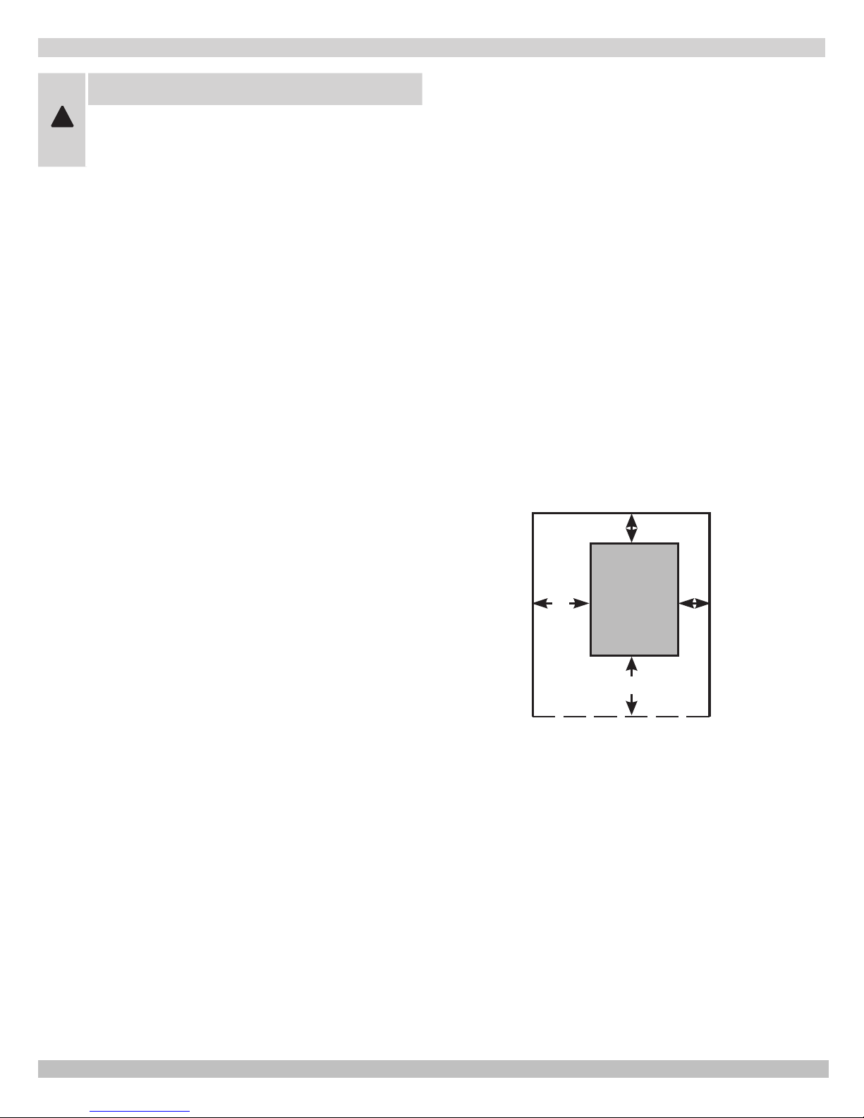
NOTE: Greater clearances for access should supersede fire
protection clearances.
* Denition of Alcove is three sided space with no wall in
front of boiler. ANSI standard for alcove is 18 inches from
front of appliance to leading edge of side walls as shown
below.
Minimum Clearances to Combustible
Construction (as seen from above)
4"
3"
9"
BOILER
18"
5
VENTILATION & COMBUSTION AIR
Provide combustion air and ventilation air in accordance
with the section “Air for Combustion and Ventilation,” of the
National Fuel Gas Code, ANSI Z223.1/NFPA 54, or Sections
8.2, 8.3 or 8.4 of Natural Gas and Propane Installation
Code, CAN/CSA B149.1, or applicable provisions of local
building codes.
Provide make-up air where exhaust fans, clothes dryers,
and kitchen ventilation equipment interfere with proper
operation.
National Fuel Gas Code recognizes several methods
of obtaining adequate ventilation and combustion air.
Requirements of the authority having jurisdiction may
override these methods.
• Engineered Installations. Must be approved by
authority having jurisdictions.
• Mechanical Air Supply. Provide minimum of 0.35
cfm per Mbh for all appliances located within space.
Additional requirements where exhaust fans installed.
Interlock each appliance to mechanical air supply
system to prevent main burner operation when
mechanical air supply system not operating.
• All Indoor Air. Calculate minimum volume for all
appliances in space. Use a different method if
minimum volume not available.
о Standard Method. Cannot be used if known air
inltration rate is less than 0.40 air changes per
National Gas and Propane Installation Code Requires
providing air supply in accordance with:
hour. See Table 3 for space with boiler only. Use
equation for multiple appliances.
Volume ≥ 50 ft3 x Total Input [Mbh]
о Known Air Inltration Rate. See Table 3 for
space with boiler only. Use equation for multiple
appliances. Do not use an air inltration rate
(ACH) greater than 0.60.
Volume ≥ 21 ft3/ACH x Total Input [Mbh]
о Refer to National Fuel Gas Code for opening
requirements between connection indoor spaces.
• All Outdoor Air. Provide permanent opening(s)
communicating directly or by ducts with outdoors.
о Two Permanent Opening Method. Provide opening
commencing within 12 inches of top and second
opening commencing within 12 inches of bottom
enclosure.
Direct communication with outdoors or
communicating through vertical ducts. Provide
minimum free area of 1 in2 per 4 Mbh of total
input rating of all appliances in enclosure.
Communicating through horizontal ducts.
Provide minimum free area of 1 in2 per 2
Mbh of total input rating of all appliances in
enclosure.
о One Permanent Opening Method. Provide opening
commencing within 12 inches of top of enclosure.
Provide minimum clearance of 1 inch on sides
and back and 6 inches on front of boiler (does not
supersede clearance to combustible materials).
о Combination Indoor and Outdoor Air. Refer to
National Fuel Gas Code for additional requirements
for louvers, grilles, screens and air ducts.
• Combination Indoor and Outdoor Air. Refer to
National Fuel Gas Code for application information.
• Section 8.2 and 8.3 when combination of appliances
has a total input of up to and including 400 Mbh (120
kW).
• Section 8.4 when combination of appliances has total
input exceeding 400 Mbh (120 kW).
• Refer to Natural Gas and Propane Installation Code
for specic air supply requirements for enclosure
or structure where boiler is installed, including air
supply openings and ducts.
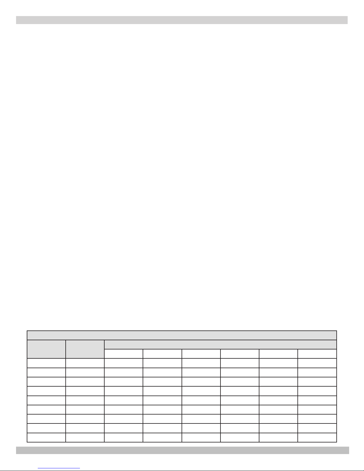
Table 3
Input Mbh
Standard
Method
0.1 0.2 0.3 0.4 0.5 0.6
50 2500 10500 5250 3500 2625 2100 1750
75 3750 15750 7875 5250 3938 3150 2625
100 5000 21000 10500 7000 5250 4200 3500
125 6250 26250 13125 8750 6563 5250 4375
150 7500 31500 15750 10500 7875 6300 5250
175 8750 36750 18375 12250 9188 7350 6125
200 10000 42000 21000 14000 10500 8400 7000
250 12500 52500 26250 17500 13125 10500 8750
300 15000 63000 31500 21000 15750 12600 10500
Known Air Inltration Rate Method (Air Changes Per Hour)
6
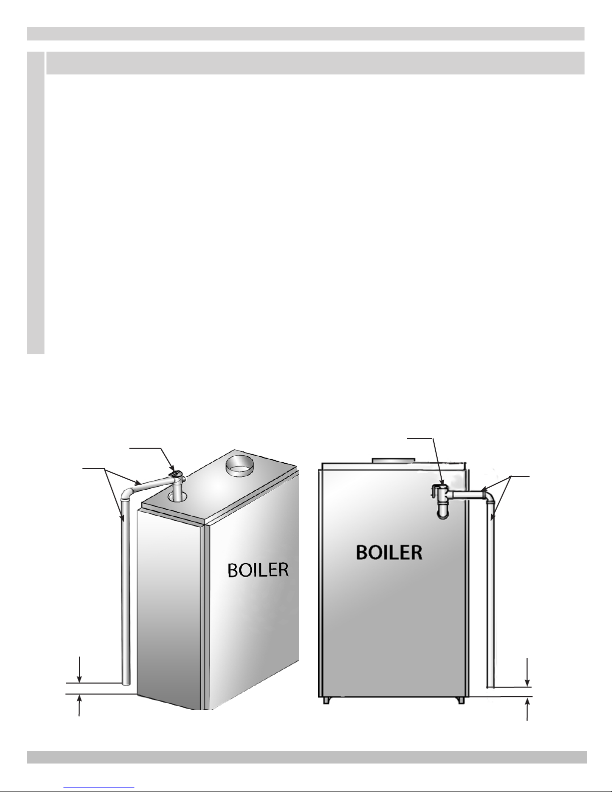
CONNECTING SUPPLY AND RETURN PIPING
WARNING
To avoid burns, scalding, or water damage due to discharge of steam and/or hot water during operation, a
discharge line shall be installed to relief valve outlet connection.
Discharge line shall:
• connect to relief valve outlet and piped down to safe point of disposal. Check local codes for
maximum distance from oor or allowable safe point of discharge.
• be of pipe size equal to or greater than that of the relief valve outlet over the entire length of
discharge line;
• have no intervening shutoff valve between safety relief valve and discharge to atmosphere (do not
plug or place any obstruction in discharge line.
• terminate freely to atmosphere where any discharge will be clearly visible and at no risk of freezing;
• allow complete drainage of the valve and the discharge line;
• be independently supported and securely anchored to avoid applied stress on the relief valve;
• be as short and straight as possible;
• terminate with plain end (not threaded);
• be constructed of material suitable for exposure to temperatures of 375° F; or greater.
Refer to local codes and appropriate ASME Boiler and Pressure Vessel Code for additional installation
requirements.
RELIEF VALVE
DISCHARGE
LINE
Check local
codes for
maximum
distance
from oor
or allowable
safe point of
discharge.
RELIEF VALVE
Check local
codes for
maximum
distance
from oor
or allowable
safe point of
discharge.
DISCHARGE
LINE
7
AIR
SEPARATOR
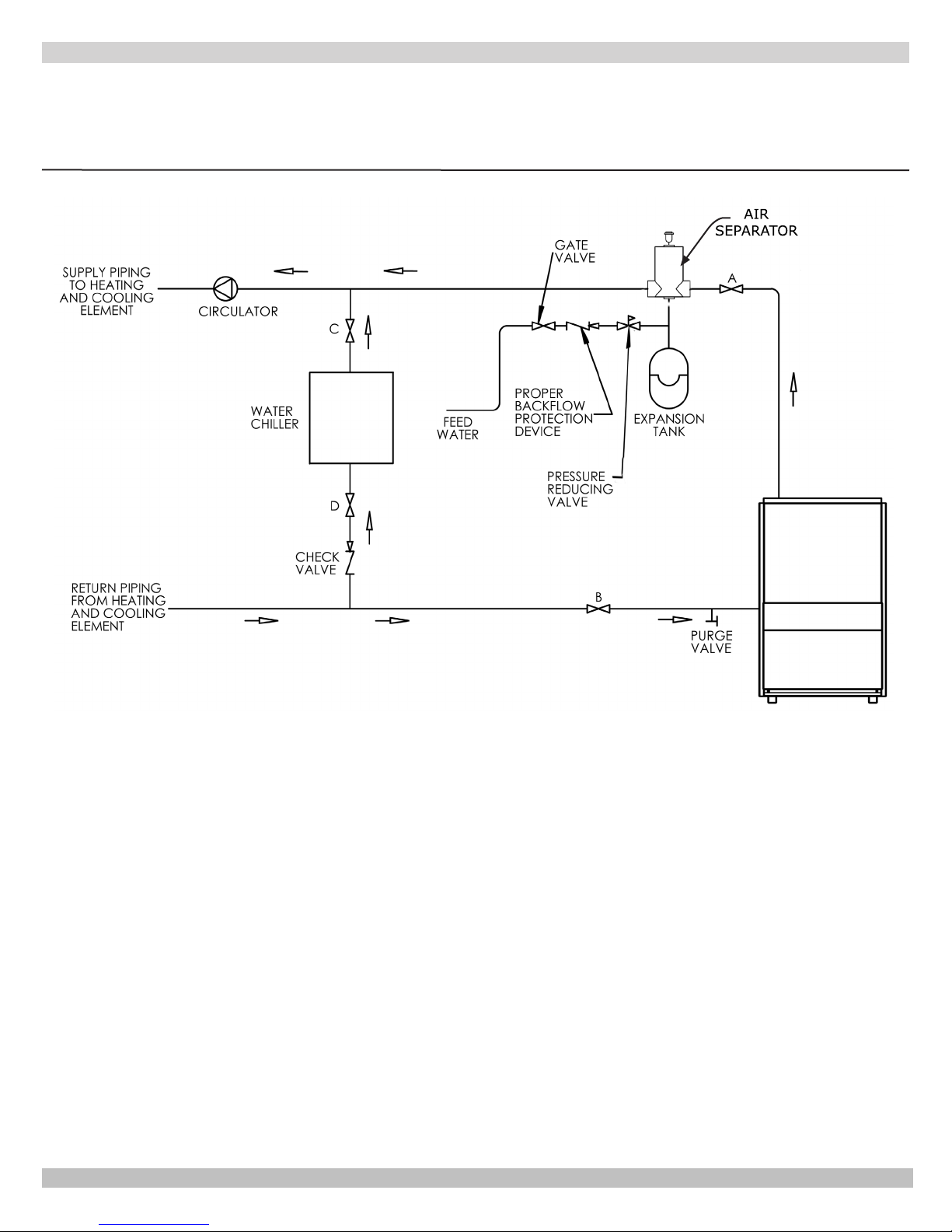
CONNECTING SUPPLY AND RETURN PIPING
IMPORTANT: Circulators in the following illustrations are mounted on the system supply side, but
mounting on the system return side is also acceptable practice.
Figure 5 - Circulators Mounted on System Supply
1.
The boiler, when used in connection with a refrigeration
system, must be installed so the chilled medium is
piped in parallel with the boiler with appropriate valves
to prevent the chilled medium from entering the boiler.
See Figure 5.
2.
The boiler piping system of a hot water boiler
connected to heating coils located in air handling
units where they may be exposed to refrigerated air
circulation must be equipped with ow control valves or
other automatic means to prevent gravity circulation of
the boiler water during the cooling cycle.
3.
Hot water boilers installed above radiation level or
as required by authority having jurisdiction must be
provided with a low water cut-off device.
4.
When a boiler is connected to a heating system that
utilizes multiple zoned circulators, each circulator must
be supplied with a ow control valve to prevent gravity
circulation.
5.
Hot water boilers and system must be lled with water
and maintained to a minimum pressure of 12 psi.
6.
Bypass piping is an option which gives the ability to
adjust the supply boiler water temperature to t the
system or the condition of the installation. This method
of piping, however, is not typically required for baseboard heating systems. Typical installations where
bypass piping is used are as follows:
A. This method is used to protect boilers from con-
densation forming due to low temperature return
water. Generally noticed in large converted gravity systems or other large water volume systems.
Figure 6 & 7.
B. These methods are used to protect systems using
radiant panels and the material they are encased in
from high temperature supply water from the boiler
and protect the boiler from condensation.
NOTE#1: When using bypass piping, adjust
valves V1 & V2 until desired system temperature
is obtained.
NOTE#2: Bypass loop must be same size piping
as the supply and return piping.
8
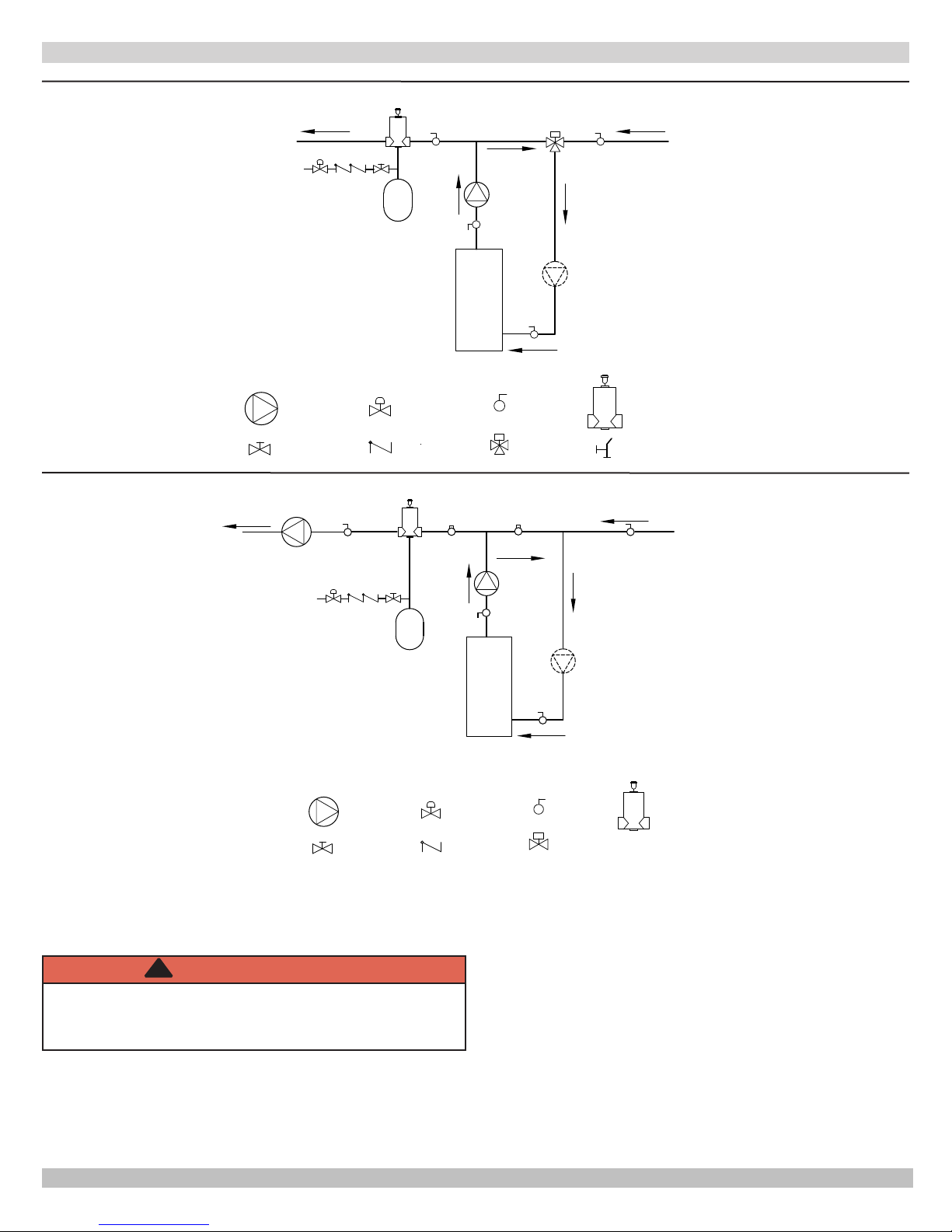
CONNECTING SUPPLY AND RETURN PIPING
Figure 6 - Bypass Piping Automatic Mixing Valve
TO SYSTEM
WATER INLET
EXPANSION
TANK
FROM SYSTEM
CIRCULATOR
SHUT-OFF
VALV E
PRESSURE
REDUCER VALVE
CHECK VALVE
BOILER
BALL VALVE
3 WAY MIXING
VALV E
ALTERNATE
CIRCULATOR
LOCATION
AIR SEPARATOR
HOSE BIB
Figure 7 - Bypass Piping - Fixed Low Temp Only Automatic Mixing Valve
TO SYSTEM
WATER INLET
SYSTEM
CIRCULATOR
EXPANSION
TANK
V2V1
BOILER
FROM SYSTEM
ALTERNATE
CIRCULATOR
LOCATION
CIRCULATOR
SHUT-OFF
VALV E
7. Installation using circulators and zone valves are
shown in Figures 8-11. For further piping information
refer to I=B=R Installation and Piping Guide.
!
WARNING
Burn and scald hazard. Safety relief valve could
discharge steam or hot water during operation.
Install discharge piping per these instructions.
8. Install discharge piping from safety relief valve.
• Use ¾" or larger pipe.
• Use pipe suitable for temperatures of 375°F (191°C)
or greater.
PRESSURE
REDUCER VALVE
CHECK VALVE
9
BALL VALVE
ZONE VALVE
AIR SEPARATOR
• Individual boiler discharge piping shall be independent
of other discharge piping.
• Size and arrange discharge piping to avoid reducing
safety relief valve relieving capacity below minimum
relief valve capacity stated on rating plate.
• Run pipe as short and straight as possible to location
protecting user from scalding and properly drain
piping.
• Install union, if used, close to safety relief valve outlet.
• Install elbow(s), if used, close to safety relief valve
outlet and downstream of union (if used).
• Terminate pipe with plain end (not threaded).
 Loading...