

Columbia MCB50, MCB75, MCB100, MCB125, MCB150 Installation, Operation & Maintenance Manual
...Page 1
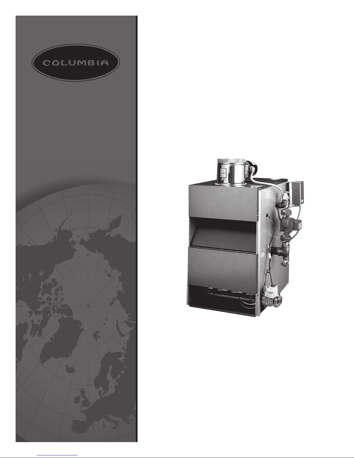
MODEL NUMBERS:
MCB50 MCB75 MCB100
MCB125 MCB150 MCB175
MCB200 MCB250 MCB300
MCB SERIES
Cast Iron Gas Fired Boilers
For Forced Hot Water
INSTALLATION, OPERATION &
MAINTENANCE MANUAL
Columbia Company
Main ofces and Factory:
Pottstown, PA
P/N 37612101, Rev. E [05/2012]
Page 2
H
INSTALLATION, OPERATION AND MAINTENANCE MANUAL
Ratings & Data - Natural Gas & Propane Gas ...........3
Dimensions .........................................................4
Installation Procedure ..........................................5
Ventilation & Combustion Air .................................6
Connecting Supply and Return Piping .....................7
Connecting Supply and Return Piping .....................8
Vent Installation ................................................ 12
Vent System Modication .................................... 12
Vent Damper Installation & Instructions ................ 13
Connecting Gas Service ...................................... 14
Electrical Section ............................................... 15
Wiring Diagram - 24V Standing Pilot .................... 16
Wiring Diagram - Intermittent Ignition ................. 17
Lighting Instructions .......................................... 18
Normal Sequence of Operation ............................ 20
General Instructions .......................................... 20
Checking Gas Input Rate To Boiler ....................... 22
KEEP THIS MANUAL NEAR BOILER
RETAIN FOR FUTURE REFERENCE
IMPORTANT: Read the following instructions
COMPLETELY before installing!!
WARNING
Keep boiler area clear and free from
combustible materials, gasoline and other
ammable vapors and liquids.
DO NOT obstruct air openings to the boiler
room.
Modication, substitution or elimination
of factory equipped, supplied or specied
components may result in property damage,
!
personal injury or the loss of life.
TO THE OWNER - Installation and service of
this boiler must be performed by a qualied
installer.
Replacement Parts - Base ................................... 23
Safety Symbols & Warnings
The following dened symbols are used throughout this
manual to notify the reader of potential hazards of varying
risk levels.
DANGER
Indicates a hazardous situation which, if
!
not avoided, WILL result in death or serious
injury.
WARNING
Indicates a hazardous situation which, if
!
not avoided, could result in death or serious
injury.
CAUTION
Indicates a hazardous situation which, if not
!
avoided, may result in minor or moderate
injury.
TO THE INSTALLER - Leave all instructions
with the boiler for future reference.
When this product is installed in the
Commonwealth of Massachusetts the
installation must be performed by a Licensed
Plumber or Licensed Gas Fitter.
WARNING
All installations of boilers and venting shall
be done only by a qualied expert and
in accordance with appropriate manual.
Installing or venting a boiler or any other gas
!
appliance with improper methods or materials
may result in serious injury or death due to
re or to asphyxiation from poisonous gases
such as carbon monoxide which is odorless
and invisible.
NOTICE
Indicates information which should be
followed to ensure proper installation and
operation.
C.S.A. Certied
For Natural Gas Or Propane
2
Tested For 100 psi.
ASME
Working Pressure
Page 3
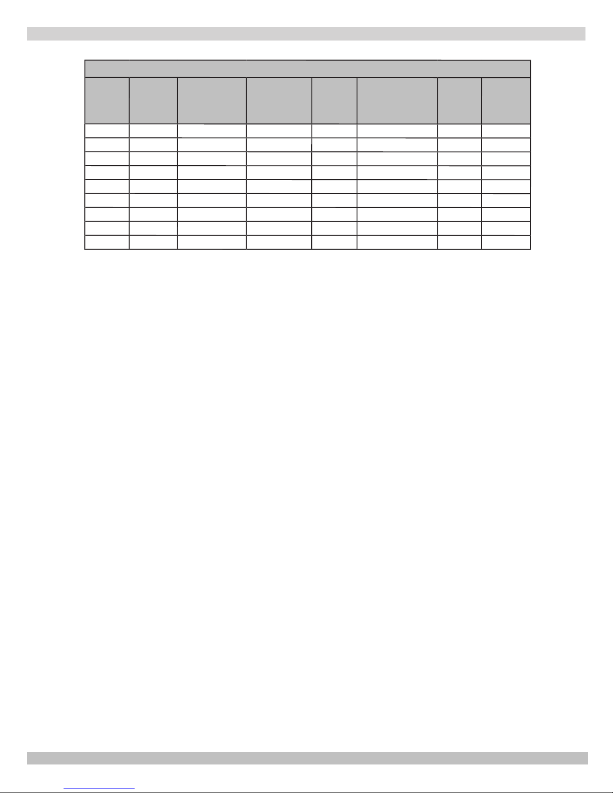
RATINGS & DATA - NATURAL GAS & PROPANE GAS
Table 1 - Ratings and Capacities
(2)
**
Net Rating
Water
Mbh
37
55
72
90
108
124
143
178
214
No.
of
Burners
1
2
2
3
3
4
4
5
6
Boiler
No.
50
75
100
125
150
175
200
250
300
(1)
Input
Mbh
50
75
100
125
150
175
200
250
299
(1)
Heating
Capacity Mbh
42
63
83
104
124
143
165
205
243
EXPLANATORY NOTES
-- All boilers are design certied for installation on noncombustible oor.
-- For installation on combustible oors use combustible oor kit.
(3)
Recommended
Air Cushion
Tank
15
15
30
30
30
30
30
30
60
Water
Content
(Gals.)
2.4
4.0
4.0
5.6
5.6
7.2
7.2
8.8
10.4
High
Altitude
Input
45,000
67,500
90,000
112,500
135,000
157,000
180,000
225,000
270,000
-- Recommended chimney height 20 feet. In special cases where conditions permit, chimney height may be
reduced to 10 feet. Refer to the latest revision of NFGC part 11.
-- Electric service to be 120 Volts, 15 Amps, 60 Hz.
-- The MEA number for the this boiler is 19-79-E.
(1) Input rating for sea level to 2,000 ft. (610m) above sea level.
• United States, over 2000 ft (610m) above sea level. Reduce input rate 4% for every 1000 ft (304m) above sea
level.
• Canada, 2000 ft (610m) to 4500 (1350m) above sea level. Reduce input per table.
• Canada, over 4500 ft (1350m) above sea level. Contact Provincial authority having jurisdiction.
(2) Net Water Ratings shown based on piping and pickup allowance of 1.15. Consult manufacturer before
selecting boiler for installations having unusual piping and pickup requirements, such as intermittent
system operation, extensive piping systems, etc.
For forced hot water systems where boiler and all piping within area to be heated, boiler may be selected
on basis of its heating capacity.
(3) Tank sized for non-ferrous baseboard or radiant panel systems. Increase size for cast iron baseboard and
radiation.
STANDARD EQUIPMENT: Boiler Jacket, Cast Iron Boiler Battery, High Limit Control, Vent Damper Relay,
Theraltimeter Gauge, Circulator With Return Piping To Boiler, Main Gas Burners, Combination 24 Volt Gas Control
(Includes Automatic Gas Valve, Gas Pressure Regulator, Automatic Pilot, Safety Shutoff, Pilot Flow Adjustment, Pilot
Filter), A.S.M.E. Relief Valve, Drain Valve, Spill Switch, Rollout Switch, Automatic Vent Damper. Not Shown Are:
Wiring Harness, Thermocouple, Non-linting Safety Pilot.
OPTIONAL EQUIPMENT: Intermittent Electric Ignition Pilot System.
3
Page 4
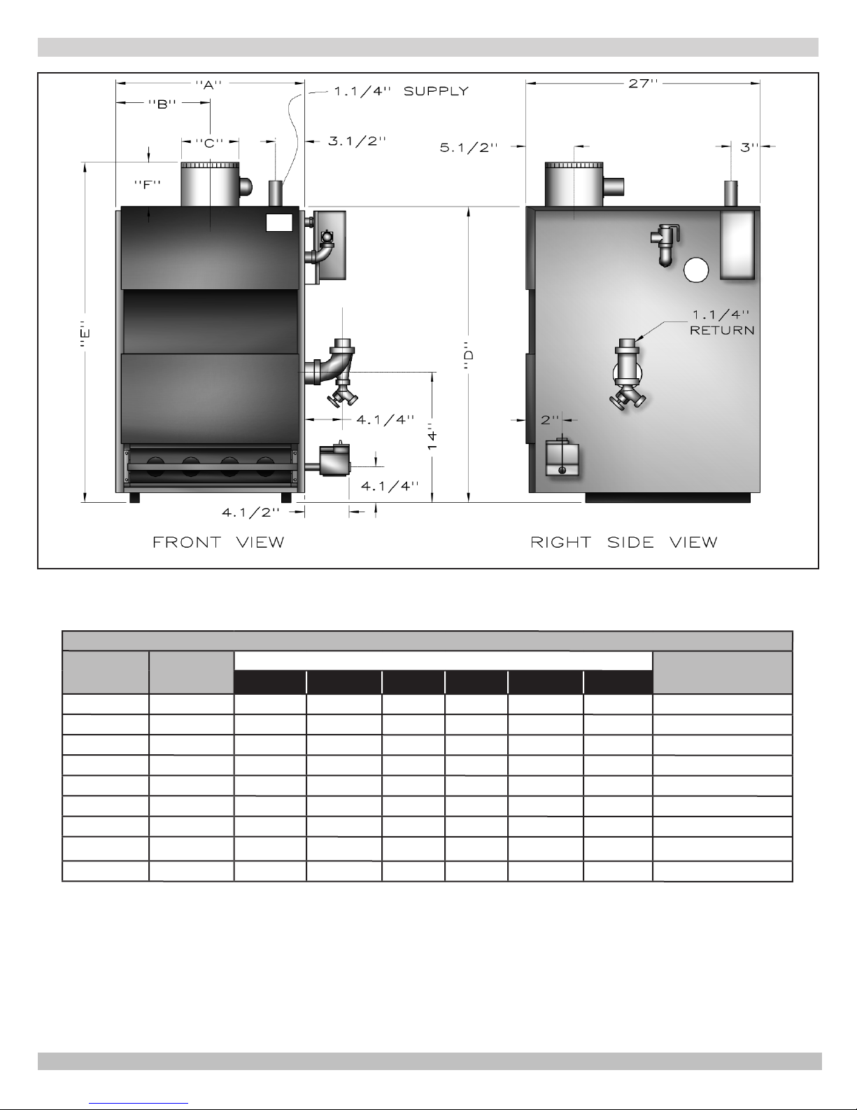
DIMENSIONS
Table 2 - Dimensions
Boiler No.
50
75
100
125
150
175
200
250
300
* Propane gas inlet, all units, 1/2"
Natural Gas
Inlet*
½"
½"
½"
½"
½"
½"
½"
¾"
¾"
26
A
11⅛"
15
15
18⅞"
18⅞"
22
¾
22
¾
13
30½"
Dimensions
B
5
½
"
7
½
"
7
½
"
9
½
"
9
½
"
"
"
⁄
"
16
11
½
11
½
13¼"
"
"
15¼"
4"
5"
6"
6"
7"
7"
8"
8"
9"
C
D
30¾"
30¾"
30¾"
30¾"
30¾"
30¾"
30¾"
30¾"
30¾"
E
36¼"
37¾"
37¼"
37¼"
37¾"
38¾"
38¾"
40¾"
42¾"
F
6"
6"
6½"
6½"
7"
7"
8"
8"
10"
Pump size Supply &
Return Tappings
1¼"
1¼"
1¼"
1¼"
1¼"
1¼"
1¼"
1¼"
1¼"
4
Page 5
INSTALLATION PROCEDURE
WARNING
Improper installation, adjustment, alteration,
!
service or maintenance can cause injury or
property damage.
1.
Installation must conform to the requirements of the
authority having jurisdiction or, in the absence of such
requirements, to the National Fuel Gas Code, ANSI
Z223.1/NFPA 54, and/or Natural Gas and Propane
Installation Code, CAN/CSA B149.1.
2.
Where required by the authority having jurisdiction, the
installation must conform to the Standard for Controls
and Safety Devices for Automatically red Boilers,
ANSI/ASME CSD-1.
3.
This boiler series is classied as a Category I. Vent
installation shall be in accordance with "Venting of
Equipment ," of the National Fuel Gas Code, ANSI
Z223.1/NFPA 54, or "Venting Systems and Air Supply
for Appliances," of the Natural Gas and Propane
Installation Code, CAN/CSA B149.1, or applicable
provisions of the local building codes.
4.
This boiler has met safe lighting and other performance
criteria with gas manifold and control assembly on the
boiler per the latest revision of ANSI Z21.13/CGA 4.9.
5.
The boiler shall be installed such that the gas ignition
system components are protected from water
(dripping, spraying, rain, etc.) during appliance
operation and service, (circulator replacement,
condensate trap, control replacement, etc.).
6.
Locate boiler on level, solid base as near the chimney
as possible and centrally located with respect to the
heat distribution system as practical.
7.
Allow 24 inches (610mm) at front and right side for
servicing and cleaning.
8.
When installed in utility room, door should be wide
enough to allow largest boiler part to enter, or to
permit replacement of another appliance such as water
heater.
9.
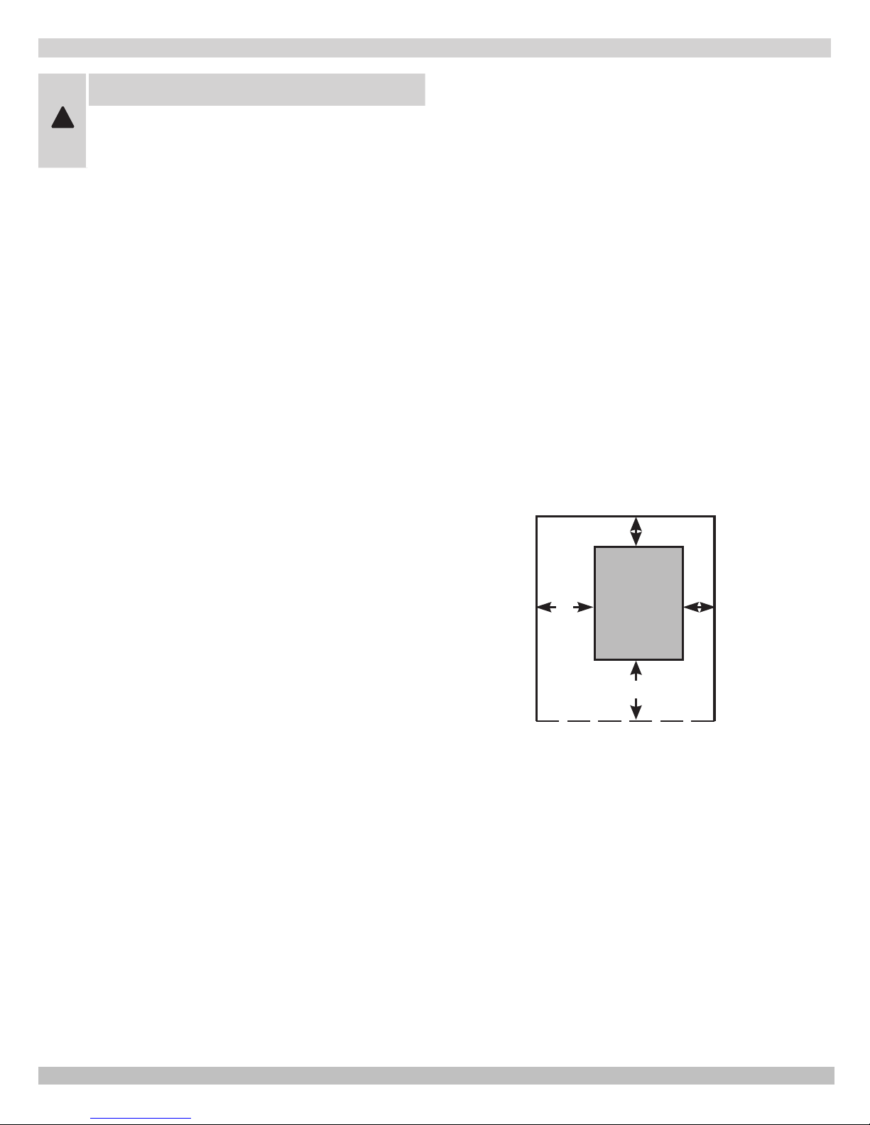
FOR INSTALLATION ON NON-COMBUSTIBLE
FLOORS ONLY - For installation on combustible
ooring special base must be used. (See Replacement
Parts Section.) Boiler can not be installed on
carpeting. Minimum clearances to combustible
construction are:
TOP ....................................18 IN. (457mm)
FRONT .........................................ALCOVE *
FLUE CONNECTOR ................. 6 IN. (152mm)
REAR ................................... 4 IN. (102mm)
CONTROL SIDE ..................... 9 IN. (229mm)
OTHER SIDE ........................... 3 IN. (76mm)
HOT WATER PIPING .............. 1/2 IN. (13mm)
NOTE: Greater clearances for access should supersede fire
protection clearances.
* Denition of Alcove is three sided space with no wall in
front of boiler. ANSI standard for alcove is 18 inches from
front of appliance to leading edge of side walls as shown
below.
Minimum Clearances to Combustible
Construction (as seen from above)
4"
3"
9"
BOILER
18"
5
Page 6
VENTILATION & COMBUSTION AIR
Provide combustion air and ventilation air in accordance
with the section “Air for Combustion and Ventilation,” of the
National Fuel Gas Code, ANSI Z223.1/NFPA 54, or Sections
8.2, 8.3 or 8.4 of Natural Gas and Propane Installation
Code, CAN/CSA B149.1, or applicable provisions of local
building codes.
Provide make-up air where exhaust fans, clothes dryers,
and kitchen ventilation equipment interfere with proper
operation.
National Fuel Gas Code recognizes several methods
of obtaining adequate ventilation and combustion air.
Requirements of the authority having jurisdiction may
override these methods.
• Engineered Installations. Must be approved by
authority having jurisdictions.
• Mechanical Air Supply. Provide minimum of 0.35
cfm per Mbh for all appliances located within space.
Additional requirements where exhaust fans installed.
Interlock each appliance to mechanical air supply
system to prevent main burner operation when
mechanical air supply system not operating.
• All Indoor Air. Calculate minimum volume for all
appliances in space. Use a different method if
minimum volume not available.
о Standard Method. Cannot be used if known air
inltration rate is less than 0.40 air changes per
National Gas and Propane Installation Code Requires
providing air supply in accordance with:
hour. See Table 3 for space with boiler only. Use
equation for multiple appliances.
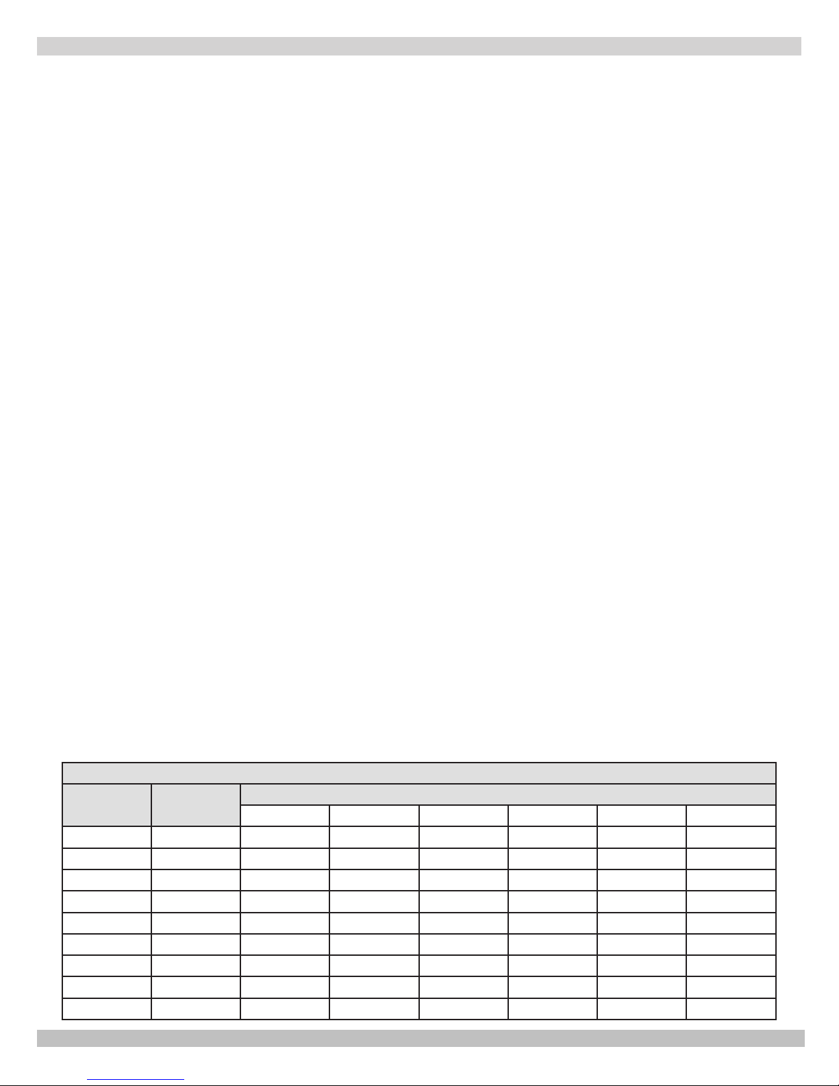
Volume ≥ 50 ft3 x Total Input [Mbh]
о Known Air Inltration Rate. See Table 3 for
space with boiler only. Use equation for multiple
appliances. Do not use an air inltration rate
(ACH) greater than 0.60.
Volume ≥ 21 ft3/ACH x Total Input [Mbh]
о Refer to National Fuel Gas Code for opening
requirements between connection indoor spaces.
• All Outdoor Air. Provide permanent opening(s)
communicating directly or by ducts with outdoors.
о Two Permanent Opening Method. Provide opening
commencing within 12 inches of top and second
opening commencing within 12 inches of bottom
enclosure.
Direct communication with outdoors or
communicating through vertical ducts. Provide
minimum free area of 1 in2 per 4 Mbh of total
input rating of all appliances in enclosure.
Communicating through horizontal ducts.
Provide minimum free area of 1 in2 per 2
Mbh of total input rating of all appliances in
enclosure.
о One Permanent Opening Method. Provide opening
commencing within 12 inches of top of enclosure.
Provide minimum clearance of 1 inch on sides
and back and 6 inches on front of boiler (does not
supersede clearance to combustible materials).
о Combination Indoor and Outdoor Air. Refer to
National Fuel Gas Code for additional requirements
for louvers, grilles, screens and air ducts.
• Combination Indoor and Outdoor Air. Refer to
National Fuel Gas Code for application information.
• Section 8.2 and 8.3 when combination of appliances
has a total input of up to and including 400 Mbh (120
kW).
• Section 8.4 when combination of appliances has total
input exceeding 400 Mbh (120 kW).
• Refer to Natural Gas and Propane Installation Code
for specic air supply requirements for enclosure
or structure where boiler is installed, including air
supply openings and ducts.
Table 3
Input Mbh
Standard
Method
0.1 0.2 0.3 0.4 0.5 0.6
50 2500 10500 5250 3500 2625 2100 1750
75 3750 15750 7875 5250 3938 3150 2625
100 5000 21000 10500 7000 5250 4200 3500
125 6250 26250 13125 8750 6563 5250 4375
150 7500 31500 15750 10500 7875 6300 5250
175 8750 36750 18375 12250 9188 7350 6125
200 10000 42000 21000 14000 10500 8400 7000
250 12500 52500 26250 17500 13125 10500 8750
300 15000 63000 31500 21000 15750 12600 10500
Known Air Inltration Rate Method (Air Changes Per Hour)
6
Page 7
CONNECTING SUPPLY AND RETURN PIPING
WARNING
To avoid burns, scalding, or water damage due to discharge of steam and/or hot water during operation, a
discharge line shall be installed to relief valve outlet connection.
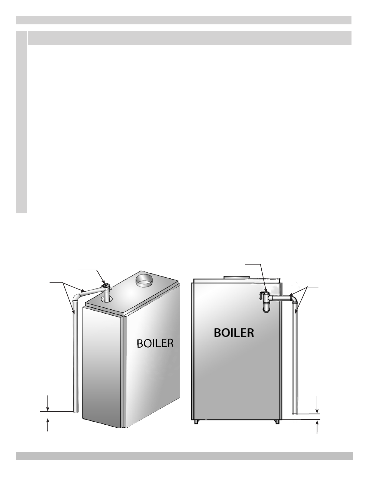
Discharge line shall:
• connect to relief valve outlet and piped down to safe point of disposal. Check local codes for
maximum distance from oor or allowable safe point of discharge.
• be of pipe size equal to or greater than that of the relief valve outlet over the entire length of
discharge line;
• have no intervening shutoff valve between safety relief valve and discharge to atmosphere (do not
plug or place any obstruction in discharge line.
• terminate freely to atmosphere where any discharge will be clearly visible and at no risk of freezing;
• allow complete drainage of the valve and the discharge line;
• be independently supported and securely anchored to avoid applied stress on the relief valve;
• be as short and straight as possible;
• terminate with plain end (not threaded);
• be constructed of material suitable for exposure to temperatures of 375° F; or greater.
Refer to local codes and appropriate ASME Boiler and Pressure Vessel Code for additional installation
requirements.
RELIEF VALVE
DISCHARGE
LINE
Check local
codes for
maximum
distance
from oor
or allowable
safe point of
discharge.
RELIEF VALVE
Check local
codes for
maximum
distance
from oor
or allowable
safe point of
discharge.
DISCHARGE
LINE
7
Page 8
AIR
SEPARATOR
CONNECTING SUPPLY AND RETURN PIPING
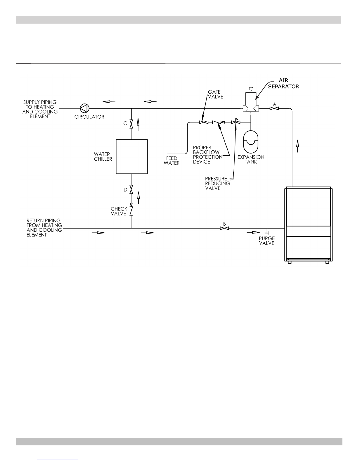
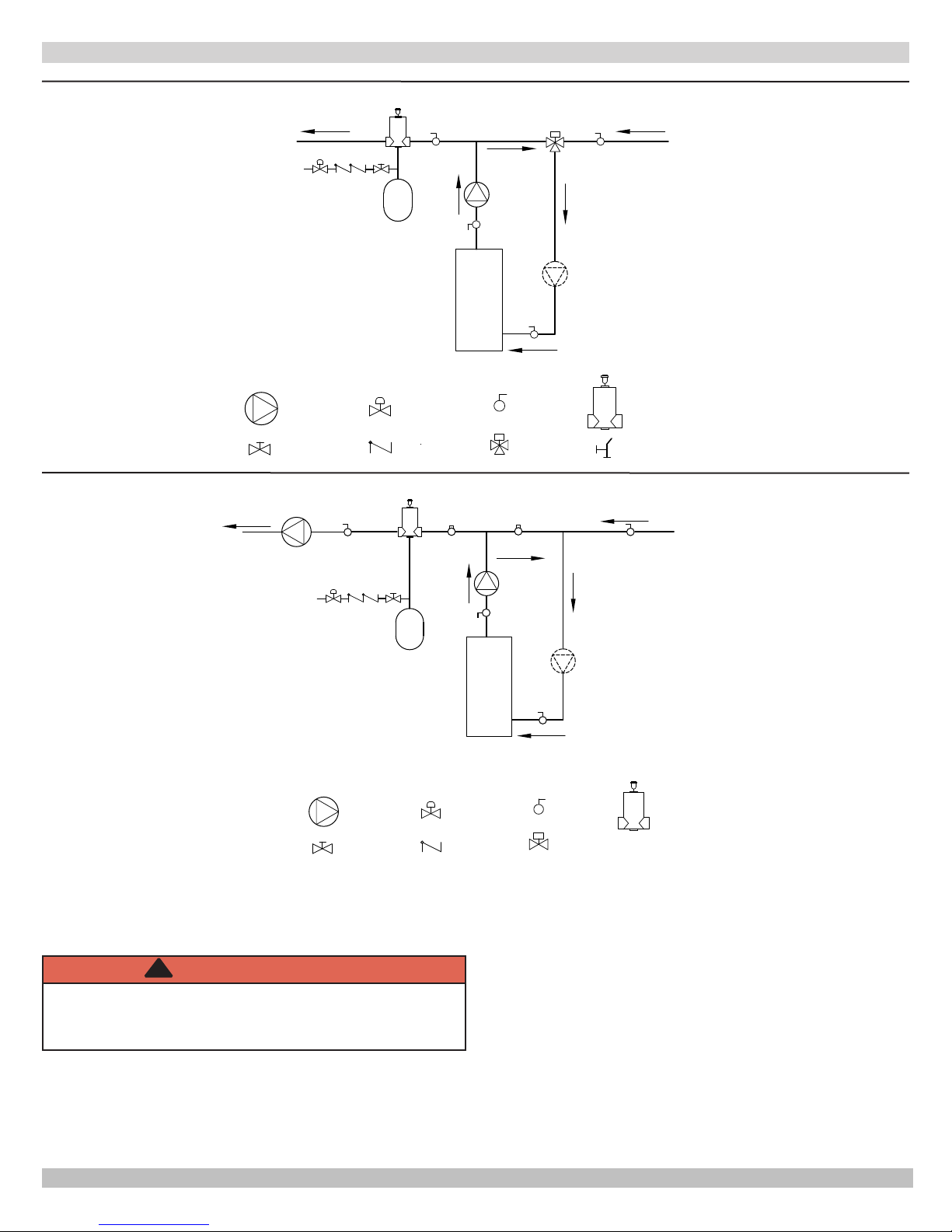
IMPORTANT: Circulators in the following illustrations are mounted on the system supply side, but
mounting on the system return side is also acceptable practice.
Figure 5 - Circulators Mounted on System Supply
1.
The boiler, when used in connection with a refrigeration
system, must be installed so the chilled medium is
piped in parallel with the boiler with appropriate valves
to prevent the chilled medium from entering the boiler.
See Figure 5.
2.
The boiler piping system of a hot water boiler
connected to heating coils located in air handling
units where they may be exposed to refrigerated air
circulation must be equipped with ow control valves or
other automatic means to prevent gravity circulation of
the boiler water during the cooling cycle.
3.
Hot water boilers installed above radiation level or
as required by authority having jurisdiction must be
provided with a low water cut-off device.
4.
When a boiler is connected to a heating system that
utilizes multiple zoned circulators, each circulator must
be supplied with a ow control valve to prevent gravity
circulation.
5.
Hot water boilers and system must be lled with water
and maintained to a minimum pressure of 12 psi.
6.
Bypass piping is an option which gives the ability to
adjust the supply boiler water temperature to t the
system or the condition of the installation. This method
of piping, however, is not typically required for baseboard heating systems. Typical installations where
bypass piping is used are as follows:
A. This method is used to protect boilers from con-
densation forming due to low temperature return
water. Generally noticed in large converted gravity systems or other large water volume systems.
Figure 6 & 7.
B. These methods are used to protect systems using
radiant panels and the material they are encased in
from high temperature supply water from the boiler
and protect the boiler from condensation.
NOTE#1: When using bypass piping, adjust
valves V1 & V2 until desired system temperature
is obtained.
NOTE#2: Bypass loop must be same size piping
as the supply and return piping.
8
Page 9
CONNECTING SUPPLY AND RETURN PIPING
Figure 6 - Bypass Piping Automatic Mixing Valve
TO SYSTEM
WATER INLET
EXPANSION
TANK
FROM SYSTEM
CIRCULATOR
SHUT-OFF
VALV E
PRESSURE
REDUCER VALVE
CHECK VALVE
BOILER
BALL VALVE
3 WAY MIXING
VALV E
ALTERNATE
CIRCULATOR
LOCATION
AIR SEPARATOR
HOSE BIB
Figure 7 - Bypass Piping - Fixed Low Temp Only Automatic Mixing Valve
TO SYSTEM
WATER INLET
SYSTEM
CIRCULATOR
EXPANSION
TANK
V2V1
BOILER
FROM SYSTEM
ALTERNATE
CIRCULATOR
LOCATION
CIRCULATOR
SHUT-OFF
VALV E
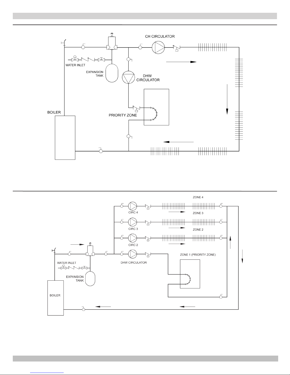
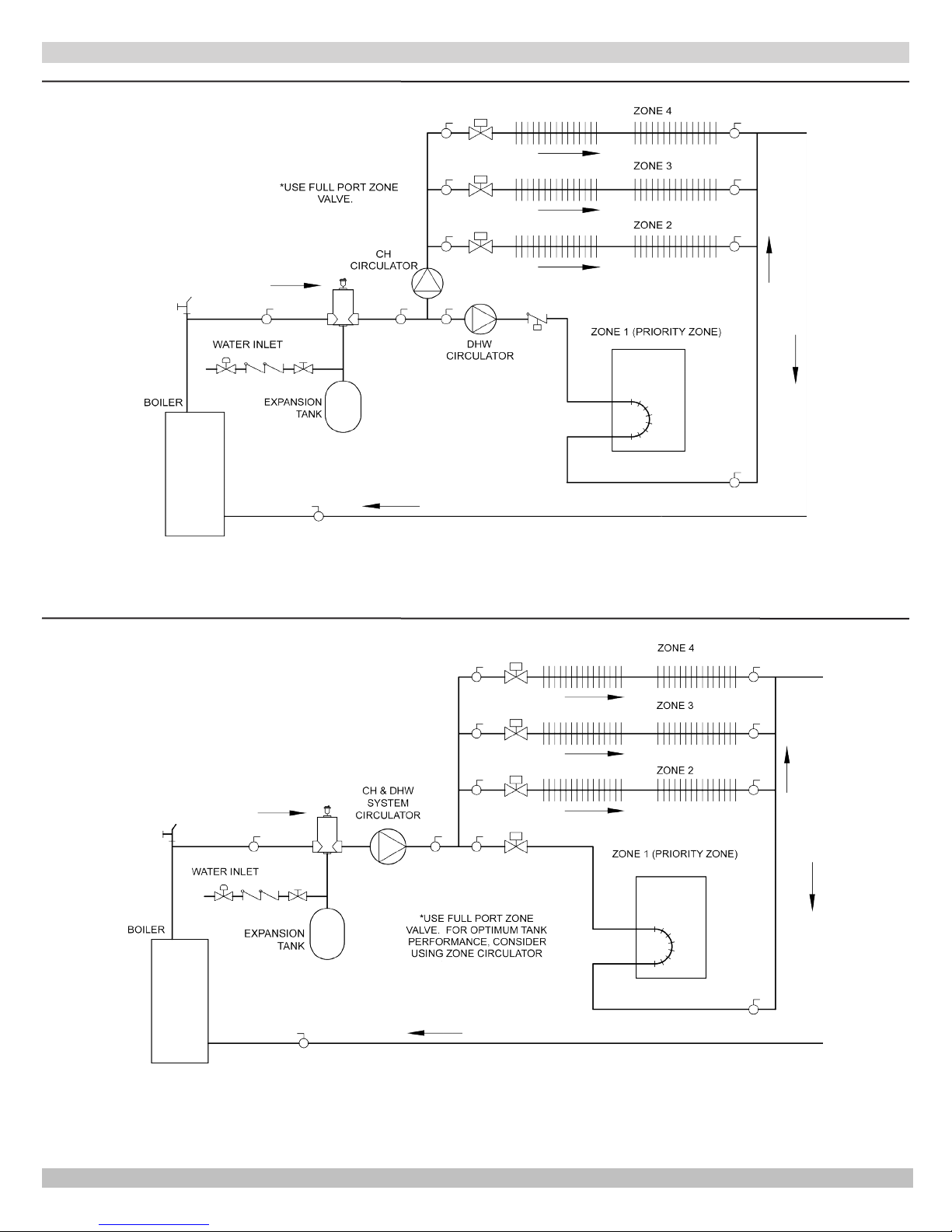
7. Installation using circulators and zone valves are
shown in Figures 8-11. For further piping information
refer to I=B=R Installation and Piping Guide.
!
WARNING
Burn and scald hazard. Safety relief valve could
discharge steam or hot water during operation.
Install discharge piping per these instructions.
8. Install discharge piping from safety relief valve.
• Use ¾" or larger pipe.
• Use pipe suitable for temperatures of 375°F (191°C)
or greater.
PRESSURE
REDUCER VALVE
CHECK VALVE
9
BALL VALVE
ZONE VALVE
AIR SEPARATOR
• Individual boiler discharge piping shall be independent
of other discharge piping.
• Size and arrange discharge piping to avoid reducing
safety relief valve relieving capacity below minimum
relief valve capacity stated on rating plate.
• Run pipe as short and straight as possible to location
protecting user from scalding and properly drain
piping.
• Install union, if used, close to safety relief valve outlet.
• Install elbow(s), if used, close to safety relief valve
outlet and downstream of union (if used).
• Terminate pipe with plain end (not threaded).
Page 10
CONNECTING SUPPLY AND RETURN PIPING
Figure 8 - Single Zone System With DHW Priority
Figure 9 - Multi Zone System With Circulators And DHW Priority
10
Page 11
CONNECTING SUPPLY AND RETURN PIPING
Figure 10 - Multi Zone System With Zone Valves And DHW Priority (With Circulator)
Figure 11 - Multi Zone System With Zone Valves And Dhw Priority (With Zone Valve)
11
Page 12

VENT INSTALLATION
WARNING
All installations of boilers and venting should
be done only by a qualied expert and in
accordance with the appropriate manual.
Installing or venting a boiler or any other gas
!
appliance with improper methods or materials
may result in serious injury or death due to
re or to asphyxiation from poisonous gases
such as carbon monoxide with is odorless and
invisible.
WARNING
This boiler shall not be connected to any
!
portion of a mechanical draft system operating
under positive pressure.
1.
The vent pipe must slope upward from the boiler not
less then ¼ inch for every 1 foot (21mm/m) to vent
terminal.
2.
Horizontal portions of the venting system shall be
supported rigidly every 5 feet and at the elbows. No
portion of the vent pipe should have any dips or sags.
3.
This boiler series is classied as a Category I. Vent
installation shall be in accordance with "Venting of
Equipment," of the National Fuel Gas Code, ANSI
Z223.1/NFPA 54, or "Venting Systems and Air Supply
for Appliances," of the Natural Gas and Propane
Installation Code, CAN/CSA B149.1, or applicable
provisions of the local building codes.
4.
Inspect chimney to make certain it is constructed
according to NFPA 211. The vent or vent connector
shall be Type B or metal pipe having resistance to heat
and corrosion not less than that of galvanized sheet
steel or aluminum not less than 0.016 inch thick (No.
28 Ga).
5.
Connect ue pipe from draft hood to chimney. Bolt or
screw joints together to avoid sags. Flue pipe should
not extend beyond inside wall of chimney. Do not
install manual damper in ue pipe or reduce size of
ue outlet except as provided by the latest revision of
ANSI Z223.13 or CAN/CSA B149.1. Protect combustible
ceiling and walls near ue pipe with reproof insulation.
Where two or more appliances vent into a common
ue, the area of the common ue must be at least
equal to the area of the largest ue plus 50 percent of
the area of each additional ue.
VENT SYSTEM MODIFICATION
When an existing boiler is removed from a common
venting system, the system is likely to be too large for the
proper venting of the appliances sill connected to it. If
this situation occurs, the following test procedure must be
followed:
REMOVAL OF BOILER FROM VENTING SYSTEM
At the time of removal of an existing boiler, the following
steps shall be followed with each appliance remaining
connected to the common venting system placed in
operation, while the other appliances remaining connected
to the common venting system are not in operation.
1.
Seal an unused opening in the common venting
system.
2.
Visually inspect the venting system for proper size and
horizontal pitch and determine there is no blockage or
restriction, leakage, corrosion and other deciencies
which could cause an unsafe condition.
3.
Insofar as is practical, close all building doors and
windows and all doors between the space in which the
appliances remaining connected to the common venting
system are located and other spaces of the building.
Turn on clothes dryers and any other appliance not
connected to the common venting system. Turn on
any exhaust fans, such as range hoods and bathroom
exhausts, so they operate at maximum speed. Do
not operate a summer exhaust fan. Close replace
dampers.
4.
5.
6.
7.
Place in operation the appliance being inspected. Follow
the lighting instructions. Adjust thermostat so appliance
will operate continuously.
Test for spillage at the draft hood relief opening after
5 minutes of main burner operation. Use the ame of
a match or candle, or smoke from a cigarette, cigar or
pipe.
After it has been determined that each appliance
remaining connected to a common venting system
properly vents when tested as outlined above, return
doors, windows, exhaust fans, replace dampers and
any other gas burning appliances to their previous
condition of use.
Any improper operation of the common venting system
should be corrected so the installation conforms with
the National Fuel gas Code, ANSI Z223.1/NFPA 54,
and/or the Natural Gas and Propane Installation Code,
CAN/CSA B149.1. When re-sizing any portion of the
common venting system, the common venting system
should be re-sized to approach the minimum size
determined using the appropriate tables in Chapter 13
of the National Fuel Gas Code, ANSI Z223.1/NFPA 54,
and/or the Natural Gas and Propane Installation Code,
CAN/CSA B149.1.
12
Page 13
VENT DAMPER INSTALLATION & INSTRUCTIONS
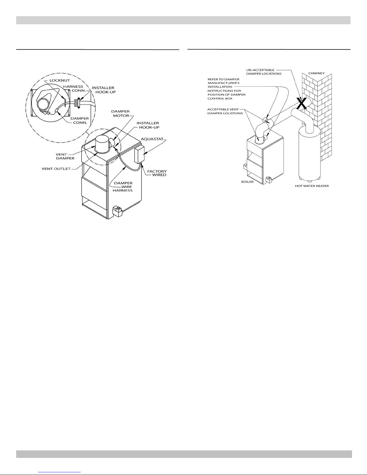
DAMPER INSTALLATION
NOTE: Refer to Figure 11 for steps 1-6.
Figure 12 - Damper Motor Wiring
DAMPER INSTRUCTIONS
Figure 13 - Vent Damper Placement
1.
Place Vent Damper on or as close to vent outlet of
boiler as possible. Figure 13.
2.
Remove Vent Damper Motor cover.
3.
Feed damper wire harness connector through bracket
hole on Damper Motor frame.
4.
Tighten locknut onto Damper wire harness connector.
5.
Plug Damper connector into socket on Damper Motor
frame.
6.
Replace Damper Motor cover and wire Damper in
accordance with Figure 12.
1.
Verify only boiler is serviced by Vent Damper. Figure
13.
2.
Clearance of not less than 6 inches (152mm) between
Vent Damper and combustible material must be
maintained. Additional clearance should be allowed for
service of Vent Damper.
3.
Vent Damper must be in the open position when
appliance main burners are operating.
4.
The Vent Damper position indicator must be in a visible
location following installation.
5.
The thermostat's heat anticipator must be adjusted to
match the total current draw of all controls associated
with the boiler during a heating cycle.
13
Page 14
CONNECTING GAS SERVICE
WHAT TO DO IF YOU SMELL GAS
• Do not try to light any appliance.
• Do not touch any electrical switch; do not
!
Figure 14 - Gas Piping
use any phones in your building.
• Immediately call your gas supplier from
a neighbor’s phone. Follow gas supplier’s
instructions.
• If you cannot reach your gas supplier, call
the re department.
CAUTION
General
• Use piping materials and joining methods acceptable
to authority having jurisdiction. In absence of such
requirements:
• USA - National Fuel gas Code, ANSI Z223.1/NFPA 54
• Canada - Natural Gas and Propane Installation Code,
CAN/CSA B149.1
• Size and install gas piping system to provide sufcient
gas supply to meet maximum input at not less than
minimum supply pressure. See Table 5.
• Support piping with hooks straps, bands, brackets,
hangers, or building structure components to prevent or
dampen excessive vibrations and prevent strain on gas
connection. Boiler will not support piping weight.
• Use thread (joint) compound (pipe dope) suitable for
liqueed petroleum gas.
• Install eld sourced manual main shutoff valve, ground
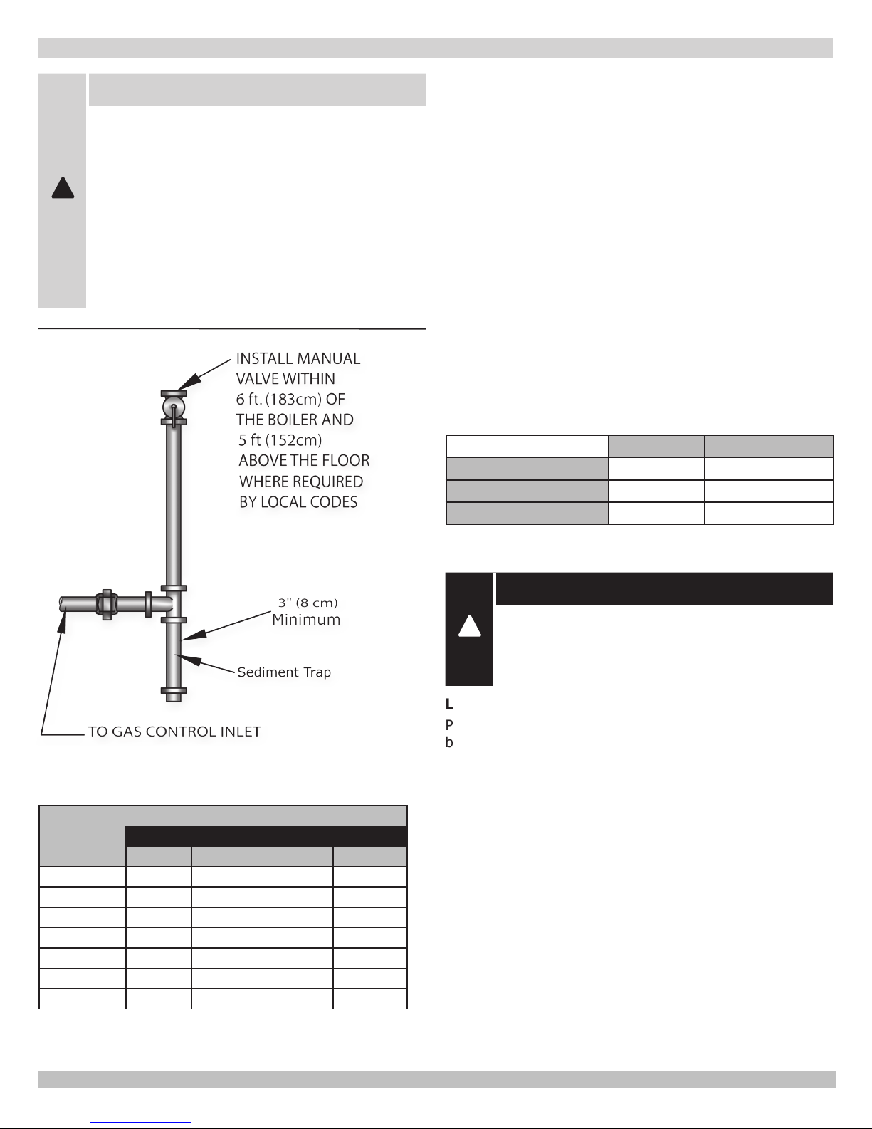
joint union, and sediment trap upstream of gas valve.
See Figure 14.
Table 5 Natural Gas Propane
Min. Supply Pressure 5" w.c. 11" w.c.
Max. Supply Pressure 13.5" w.c. 13.5" w.c.
Manifold Pressure 3.5" w.c. 10.5" w.c.
MAXIMUM CAPACITY OF PIPE IN CUBIC FEET OF GAS/HOUR
(Gas Pressure = 0.5 psig or less, Pressure Drop = 5 in. w/c)
Table 4
Length of
Pipe (Feet)
10 175 360 680 1400
20 120 250 465 950
30 97 200 375 770
40 82 170 320 660
60 66 138 260 530
80 57 118 220 460
100 50 103 195 400
For additional information refer to the National Fuel Gas
Code Handbook.
Nominal Iron Pipe Size
½” ¾” 1” 1¼”
DANGER
Fire Hazard. Do not use matches, candles,
!
open ames, or other methods providing
ignition source. Failure to comply will result in
death or serious injury.
Leak Check Gas Piping
Pressure test boiler and gas connection before placing
boiler in operation.
•
Pressure test over 1/2 psig (3.5 kPa). Disconnect
boiler and its individual gas shutoff valve from gas
supply system.
•
Pressure test at 1/2 psig (3.5 kPa) or less. Isolate
boiler from gas supply system by closing manual gas
shutoff valve.
•
Locate leakage using gas detector, noncorrosive
detection uid, or other leak detection method
acceptable to authority having jurisdiction. Do not
use matches, candles, open ames, or other methods
providing ignition source.
•
Correct leaks immediately and retest.
14
Page 15

ELECTRICAL SECTION
WARNING
Electrical shock hazard. Turn OFF electrical
!
power supply at service panel before making
electrical connections. Failure to do so could
result in death or serious injury.
ELECTRICAL WIRING
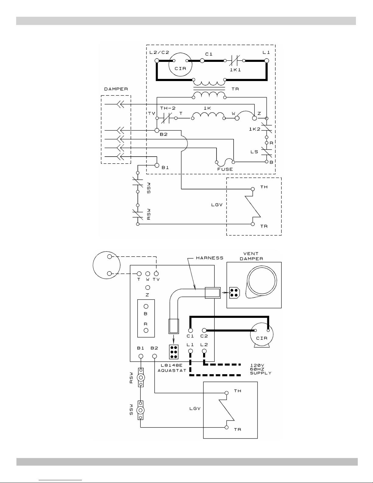
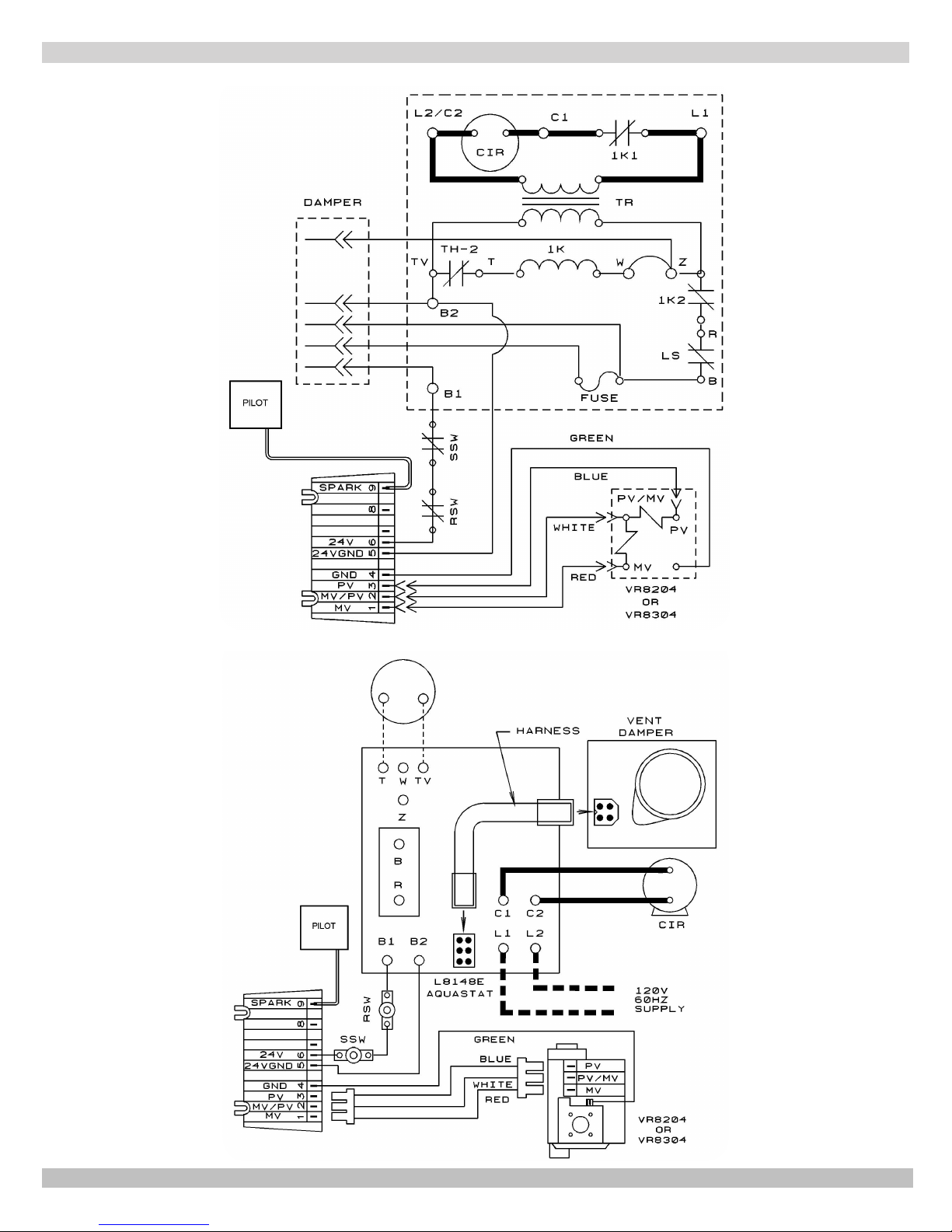
See wiring diagrams on the following two pages for
details.
Electrically bond boiler to ground in accordance with
requirements of authority having jurisdiction. Refer to:
• USA- National Electrical Code, ANSI/NFPA 70.
• Canada - Canadian Electrical Code, Part I, CSA C22.1:
Safety Standard for Electrical Installations.
THERMOSTAT INSTALLATION
1.
Thermostat should be installed on an inside wall about
four feet above the oor.
2.
NEVER install a thermostat on an outside wall.
3.
Do not install a thermostat where it will be affected
by drafts, hot or cold pipes, sunlight, lighting xtures,
televisions, a replace, or a chimney.
4.
Check thermostat operation by raising and lowering
thermostat setting as required to start and stop the
burners.
5.
Instructions for the nal adjustment of the thermostat
are packaged with the thermostat (adjusting heating
anticipator, calibration, etc.)
15
Page 16
WIRING DIAGRAM - 24V STANDING PILOT
VR8200
OR
VR8300
16
Page 17
WIRING DIAGRAM - INTERMITTENT IGNITION
17
Page 18
LIGHTING INSTRUCTIONS
WARNING
If you do not follow these instructions exactly,
a re or explosion may result, causing
property damage, personal injury or loss of
!
life.
Before any procedures are attempted on this
appliance, determine if ignition system is
electric or standing pilot. If you are uncertain,
contact manufacturer before proceeding.
WARNING
Before lighting any type of pilot burner
(standing or intermittent), make certain the
hot water boiler and system are full of water
!
to minimum pressure of 12 psi in the system,
and also verify system is vented of air. Set
operating control of thermostat to “below”
normal setting. Refer to following appropriate
lighting instruction.
D. Do not use this appliance if any part has been under
water. Immediately call a qualied service technician
to inspect appliance and to replace any part of control
system and any gas control which has been under
water.
OPERATING INSTRUCTIONS FOR INTERMITTENT PILOT SYSTEM
1.
STOP! Read the safety information to the left.
2.
Set the thermostat to lowest setting.
3.
Turn off all electric power to the appliance.
4.
This appliance is equipped with an ignition device which
automatically lights the pilot. Do not try to light the
pilot by hand.
Figure 15 - Intermittent Pilot
LIGHTING PROCEDURE FOR BOILER WITH
INTERMITTENT PILOT SYSTEM
For Your Safety, Read Before Operating!!
A. This appliance is equipped with an ignition device which
automatically lights the pilot. Do not try to light the
appliance by hand.
B. Before operating, smell all around the appliance area
for gas. Be sure to smell next to the oor because
some gas is heavier than air and will settle on the oor.
5.
6.
CAUTION
WHAT TO DO IF YOU SMELL GAS
• Do not try to light any appliance.
• Do not touch any electrical switch; do not
use any phone in your building.
!
7.
8.
9.
10.
• Immediately call your gas supplier from a
neighbor’s phone. Follow the gas supplier's
instructions.
• If you cannot reach your gas supplier, call
the re department.
Turn gas control knob clockwise to “OFF.”
Wait (5) minutes to clear out any gas. If you then smell
gas, STOP! Follow “What To Do If You Smell Gas” in the
safety information to the left. If you don’t smell gas, go
on to the next step.
Turn gas control knob counterclockwise to “ON.”
Turn on all electric power to the appliance.
Set thermostat to desired setting.
If the appliance will not operate, follow the instructions
“
To Turn Off Gas To Appliance
call a qualied service technician or your gas supplier.
” on next page, and
C. Use only your hand to push in or turn the gas control
knob. Never use tools. If the knob will not push in or
turn by hand, don’t try to repair it. Call a qualied
service technician. Force or attempted repair may
result in a re or explosion.
18
Page 19
LIGHTING INSTRUCTIONS
LIGHTING PROCEDURE FOR BOILER WITH
CONTINUOUS PILOT
For Your Safety, Read Before Lighting!!
1.
Read the warning at the beginning of "
Instructions
2.
This appliance has a pilot which must be lighted by
hand. When lighting the pilot, follow these instructions
exactly.
3.
Before lighting, smell all around the appliance area for
gas. Be sure to smell next to the oor because some
gas is heavier than air and will settle on the oor. See
section "
page
4.
Use only your hand to push in or turn gas control knob
or reset button. Never use tools. If the knob or reset
button will not push in or turn by hand, don’t try to
repair it, call a qualied service technician. Force or
attempted repair may result in a re or explosion.
5.
Do not use this appliance if any part has been under
water. Immediately call a qualied service technician
to inspect the appliance and to replace any part of the
control system and any gas control which has been
under water.
LIGHTING INSTRUCTIONS FOR CONTINUOUS PILOT
1.
STOP! Read the safety information above.
2.
Set the thermostat to the lowest setting.
3.
Turn off all electric power to the appliance.
4.
Remove access panel and burner door.
5.
Turn gas control knob clockwise to "OFF."
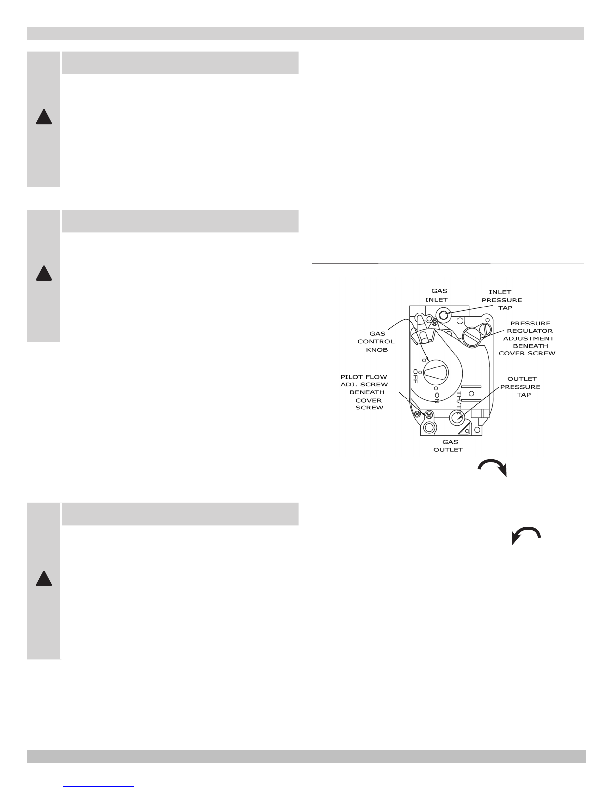
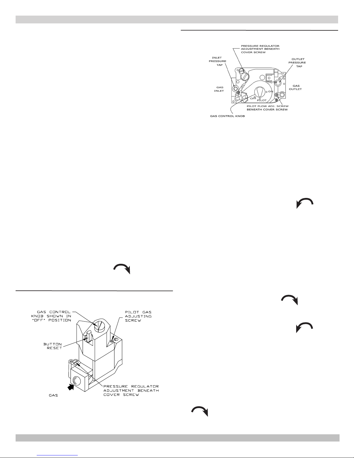
(Figures 16 and 17)
."
What To Do If You Smell Gas
Lighting
" on previous
Figure 17 - Continuous Pilot
NOTE: Some gas control knobs cannot be turned from
"PILOT" to "OFF" unless knob is pushed in slightly. DO
NOT FORCE.
6.
Wait (5) minutes to clear out any gas. If you then smell
gas, STOP! Follow "
on previous page. If you don't smell gas, go to the
next step.
7.
Find pilot. Follow metal tube from gas control. Depending on the model of the boiler, pilot is either mounted
on the base or on one of the burner tubes.
8.
Turn gas control knob counterclockwise to "PILOT."
9.
Push in gas control knob or reset button if so equipped,
all the way in and hold. Immediately light the pilot
with a match. Continue to hold the gas control knob or
reset button in for about 1 minute after the pilot is lit.
Release knob or button, and it will pop up back up. Pilot
should remain lit. If it goes out, repeat steps 5 through
9.
• If knob or button does not pop up when released,
stop and immediately call a qualied service technician or your gas supplier.
What To Do If You Smell Gas
"
Figure 16 - Gas Control Knob
INLET
• If the pilot will not stay lit after several tries, turn
the gas control knob clockwise to "OFF." Call
a qualied service technician or your gas supplier.
10.
Replace burner door.
11.
Turn gas control knob counterclockwise to "ON."
12.
Replace access panel.
13.
Turn on all electric power to the appliance.
14.
Set thermostat to desired setting.
TO TURN OFF GAS TO THE APPLIANCE
1.
Set the thermostat to lowest setting.
2.
Turn off all electric power to the appliance if service is
to be performed.
3.
Push in gas control knob slightly and turn clockwise
to "OFF." DO NOT FORCE.
4.
Call a qualied service technician.
19
Page 20
NORMAL SEQUENCE OF OPERATION
On a call for heat, the thermostat will actuate,
completing the circuit to the control. The
completed circuit to the control will rst activate
the circulator and damper which will close an
end switch inside the damper. This action will
complete the circuit to the ignition system and
ignition will take place.
In the event the boiler water temperature exceeds
the high limit setting on the boiler mounted high
limit control, power will be interrupted between
the control system and the ignition system.
The power will remain off until the boiler water
temperature drops below the high limit setting.
The circulator will continue to operate under this
condition until the thermostat is satised.
In the event the ow of combustion products
through the boiler venting system becomes
blocked, the blocked vent safety switch will shut
the main burner gas off. Similarly, if the boiler
ue-way becomes blocked, a ame rollout safety
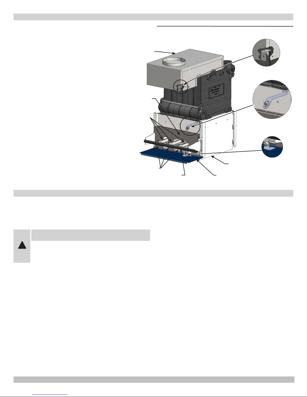
switch will shut the main burner gas off. Figure
18. If either of these conditions occur, DO
NOT ATTEMPT TO PLACE THE BOILER BACK
INTO OPERATION. CONTACT A CERTIFIED
SERVICE AGENCY.
Burners
Figure 18 - Blocked Vent Safety Switch, Roll-out
Safety Switch
Intergral Draft
Hood
Burner
Door
Orices
Manifold
Base
Jacket Base
Panel
Blocked Vent
Safety Switch
Rollout Switch
4 Section Boiler
R o l l o u t S w i t c h
2,3,5,6,7
Section Boiler
GENERAL INSTRUCTIONS
Before seasonal start-up, have a certied service agency
check the boiler for soot and scale in the ues, clean the
burners and check the gas input rate to maintain high
operating efciency.
CAUTION
Label all wires prior to disconnection when
!
servicing controls. Wiring errors can cause
improper and dangerous operation.
Verify proper operation after servicing
The service agency or owner should make certain the
system is lled with water to minimum pressure and
open air vents, if used, to expel any air that may have
accumulated in the system. Check the entire piping system
and, if any leaks appear, have them repaired.
Circulators need to be checked and maintained.
Refer to the circulator manufacturer's instructions.
The venting system should be inspected at the start of each
heating season. Check the vent pipe from the boiler to the
chimney for signs of deterioration by rust or sagging joints.
Repair if necessary. Remove the vent pipe at the base of
the chimney or ue and using a mirror, check vent for
obstruction and make certain the vent is in good working
order.
The boiler ue gas passageways may be inspected by a
light and mirror. Remove the burner door.
a trouble lamp in the ue collector through the draft relief
opening. With the mirror positioned above the burners, the
ue gas passageways can be checked for soot or scale.
The following procedure should be followed to clean the
ue gas passageways:
1.
2.
3.
4.
5.
6.
Figure 21
Remove the burners from the combustion chamber by
raising the burners up from the manifold orices and
pulling toward the front of the boiler.
Disconnect the vent pipe from the draft hood.
Remove the top jacket panel.
Remove the combination ue collector and draft hood
from the boiler castings by loosening the nuts on the
hold down bolts located on each side of the collector.
Figure 17
Place a sheet of heavy paper or similar material over
the bottom of the base and brush down the ue
passageways. The soot and scale will collect on the
paper and is easily removed with the paper.
With the paper still in place in the base, clean the top
of the boiler castings of the boiler putty or silicone
used to seal between the castings and ue collector.
Make certain that chips are not lodged in the ue
passageways.
.
Figure 21
. Place
.
20
Page 21
GENERAL INSTRUCTIONS
When the cleaning process is complete, restore the boiler
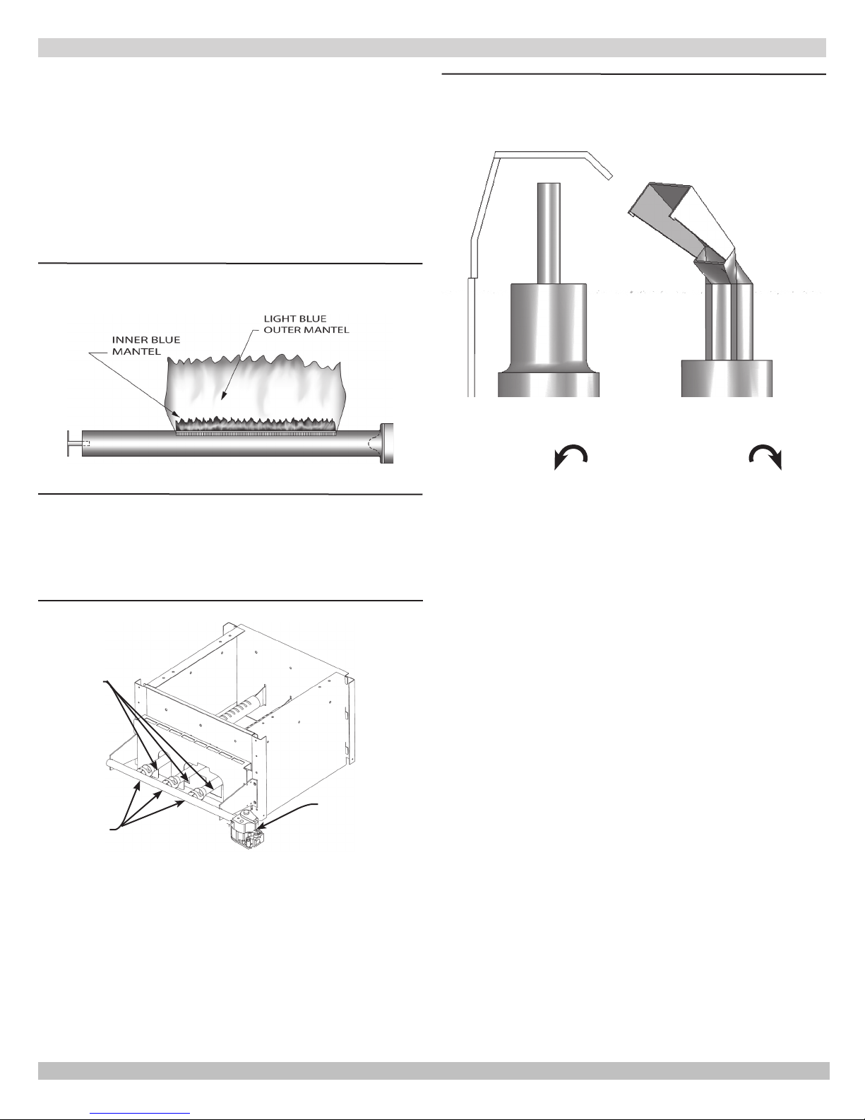
Figure 21 - Gas Burner Pilot
components to their original position. Use IS-808 GE
silicone (available from a distributor) to seal around the
ue collector and boiler castings.
A visual check of the main burner and pilot ames should
be made at the start of the heating season and again in
mid-season. The main burner ame should have a well
dened inner blue mantel with a lighter blue outer mantel.
Check the burner throats and burner orices for lint or dust
obstruction.
Figures 20 and 21
.
Figure 19 - Gas Burner Flame
To adjust the pilot ame, remove the pilot adjustment
cover screw and turn the inner adjustment screw
counterclockwise to increase or clockwise to
decrease pilot ame. Be sure to replace cover screw after
adjustment to prevent possible gas leakage. Figures 15 -
Figure 20 - Gas Burner Orices
17 on previous pages.
The burners and pilot should be checked for signs of
The pilot ame should envelop ⅜ to ½ inch of the tip of the
pilot thermocouple, ignition/sensing electrode or mercury
sensor.
Figure 21.
Figure 20 - Combustion Chamber
corrosion, rust or scale buildup. The area around the boiler
must be kept clear and free of combustible materials,
gasoline and other ammable vapors and liquids.
The free ow of combustion and ventilating air to the boiler
and boiler room must not be restricted or blocked.
Inspect eld sourced low water cutoffs annually, or as
recommended by low water cutoff manufacturer. Flush
BURNERS
oat type low water cutoffs per manufacturer's instructions.
It is recommended that a qualied service agency be
employed to make an annual inspection of the boiler and
heating system. They are experienced in making the
inspections outlined above, and, in the event repairs or
corrections are necessary, trained technicians can make the
proper changes for safe operation of the boiler.
GAS VALVE
ORIFICES
21
Page 22
CHECKING GAS INPUT RATE TO BOILER
Gas input to the boiler can be adjusted by removing the
protective cap on the pressure regulator, and turning
the screw clockwise to increase input and
counterclockwise to decrease input. The manifold
pressures are taken at the outlet side of the gas valve.
To check for proper ow of natural gas to the boiler,
divide the input rate shown on the rating plate by the
heating value of the gas obtained from the local gas
company. This will determine the number of cubic feet
of gas required per hour. With all other gas appliances
off, determine the ow of gas through the meter for
two minutes and multiply by 30 to get the hourly rate.
Make minor adjustments to the gas input as described
above. Figures 15-17.
Burner orices should be changed if the nal manifold
pressure varies more than plus or minus 0.3 inches
water column from the specied pressure.
Primary air adjustment is not necessary, therefore air
shutters are not furnished as standard equipment. Air
shutters can be furnished on request where required
by local codes or conditions.
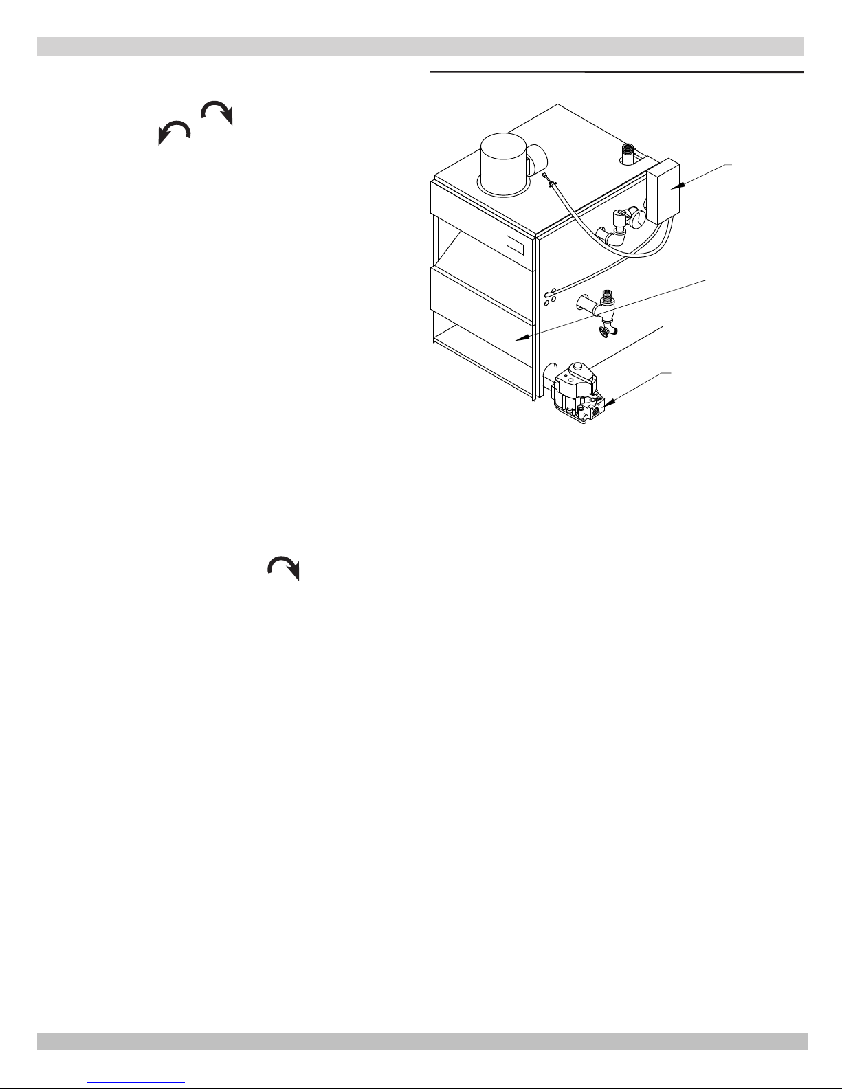
Figure 22 - High Limit Control Location
HIGH LIMIT
AND OPERATING
CONTROL
BURNER ACCESS
DOOR
GAS VALVE
CHECK SAFETY CONTROL CIRCUIT. Ignition system
safety shutoff device must be tested after placing boiler
in operation. (Figures 15-17 on previous pages)
1. Pilot: With main burner operating, turn the pilot
gas adjusting screw clockwise until pilot gas
is turned off. Within 90 seconds the main gas
control should close, shutting off the gas to the
main burner.
2. High Limit Control: Remove cover and note
temperature setting. Decrease this setting to
minimum and operate boiler. When the boiler water
temperature exceeds the control temperature
setting, the control will open the circuit, closing
the automatic main gas valve. Figure 22.
22
Page 23
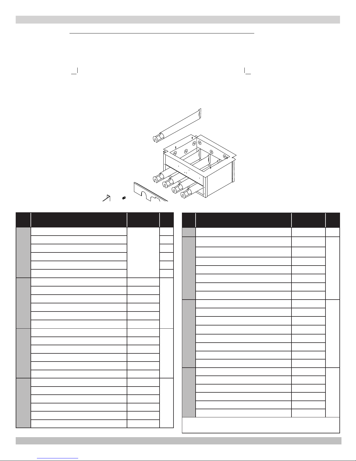
BOILER BASE
DRAWN BY:
DATE:
REPLACEMENT PARTS - BASE
UTICA BOILERS, INC.
VTB REV: 1 A1520
4/28/97
NOTE: DO NOT ALTER THIS MASTER
PART NO.:
Item
#
BURNER TUBE 1 1/2"
BURNER TUBE 1 1/2"
BURNER TUBE 1 1/2"
1
BURNER TUBE 1 1/2"
BURNER TUBE 1 1/2"
BURNER TUBE 1 1/2"
BASE W/INSUL
BASE W/INSUL
BASE W/INSUL
2
BASE W/INSUL
BASE W/INSUL
BASE W/INSUL
BURNER DOOR -
BURNER DOOR -
BURNER DOOR -
3
BURNER DOOR -
BURNER DOOR -
BURNER DOOR -
Description Part # Qty.
- 50
- 75, 100 2
- 125, 150 3
- 175, 200 4
- 250 5
- 300 6
- 50
- 75, 100
- 125, 150
- 175, 200
- 250
- 300
50
75, 100
125, 150
175, 200
250
300
MANIFOLD - 50 356-2-1.01
MANIFOLD - 75&100 356-2-1.02
MANIFOLD - 125&150 356-2-1.03
4
MANIFOLD - 175&200 356-2-1.04
MANIFOLD - 250 356-2-1.05
MANIFOLD - 300 356-2-1.06
240005543
5611601
5611602
3001823
5611604
5611605
5611606
3261201
3262701
109008513
109008514
109008515
109008516
Item
#
1
5
SCREW ¼ - 20 X ½ SELF TAP HW-005.01
GAS VALVE VR8200H
GAS VALVE VR8200H - 50 - 300 24V LP
GAS VALVE VR8204H - 50 - 150 SPARK NAT
6
GAS VALVE VR8304H4 - 175-300 SPARK NAT
GAS VALVE VR8304 - 50-300 SPARK LP
Description Part # Qty.
4
-
50 - 150 24V NAT VG-003.05
VG00307
VG01101
VG01103
1
VG01104
GAS VALVE VR8300H4 - 250 & 300 24V NAT VG01201
GAS VALVE VR8300H4 - 175 & 200 24V NAT VG01202
1
ORIFICE 3.2mm NAT - 50, 100, 150, 200, 250, & 300
240007406
ORIFICE 3.0mm NAT - 175 240007404
ORIFICE 2.9mm NAT - 125 240007403
ORIFICE 2.8mm NAT - 75
7
ORIFICE #45 LP - 50
ORIFICE #47 LP - 100, 150, 200, 250, & 300
1
ORIFICE #49 LP - 125 & 175 355-1-5.06
240007402
3551520
355-1-5.04
*
ORIFICE #50 LP - 75 355-1-5.07
COMBUSTIBLE BASE FLOORING - 50
COMBUSTIBLE BASE FLOORING - 75, 100
COMBUSTIBLE BASE FLOORING - 125, 150
COMBUSTIBLE BASE FLOORING - 175, 200
1
NOT SHOWN
COMBUSTIBLE BASE FLOORING - 250
COMBUSTIBLE BASE FLOORING - 300
*
Orice Quantities: Model 50 - qty 1; Model 75 & 100- qty 2; Model 125 & 150-
325-2-8.01
325-2-8.02
325-2-8.03
325-2-8.04
325-2-8.05
325-2-8.06
1
qty 3; Model 175 & 200- qty 4; Model 250- qty 5; Model 300- qty 6.
23
Page 24
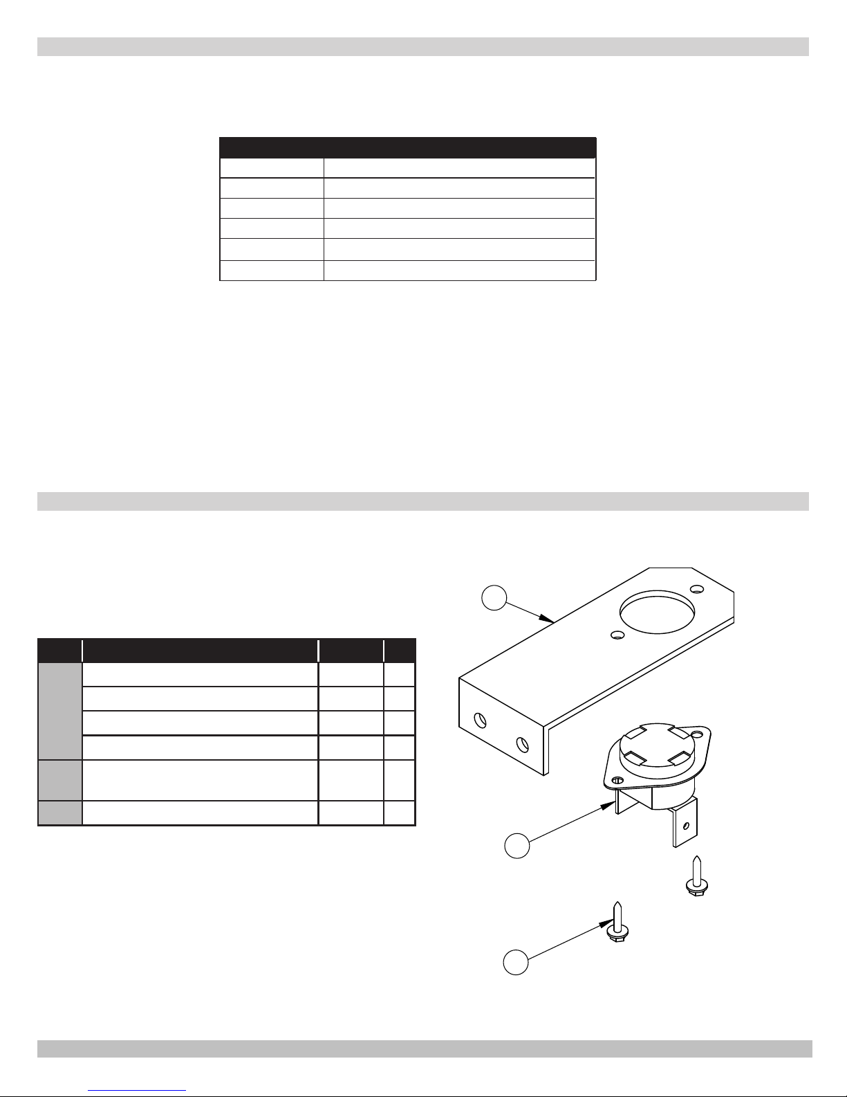
HEAT EXCHANGER
REPLACEMENT PARTS - HEAT EXCHANGER
Fully Assembled Heat Exchangers
912000001 Heat Exchanger (2 Section)
912000002 Heat Exchanger (3 Section)
912000003 Heat Exchanger (4 Section)
912000004 Heat Exchanger (5 Section)
912000005 Heat Exchanger (6 Section)
912000006 Heat Exchanger (7 Section)
ROLLOUT & SPILL SWITCH
ROLLOUT & SPILL SWITCH
Item # Description Part # Qty.
2 SECTION TEMP. SENSOR BRACKET 32611001
3 SECTION TEMP. SENSOR BRACKET
1
4 SECTION TEMP. SENSOR BRACKET
5-7 SECTION TEMP. SENSOR BRACKET
CONTROL-FIXED TEMPERATURE THERMO
2
(ROLLOUT SWITCH)
3
SCREW - #6 X ¼ HEX HD HW06501
Rollout switch is located on base and ue collector.
NOTE: Quantities above are for each switch.
3262001 1
109008517 1
109008518 1
AQ02101
1
1
1
2
2
3
24
Page 25
DATE:
DRAWN BY:
PART NO.:
NOTE: DO NOT ALTER THIS MASTER
REV:
UTICA BOILERS, INC.
4/24/97
VTB 1 A1518
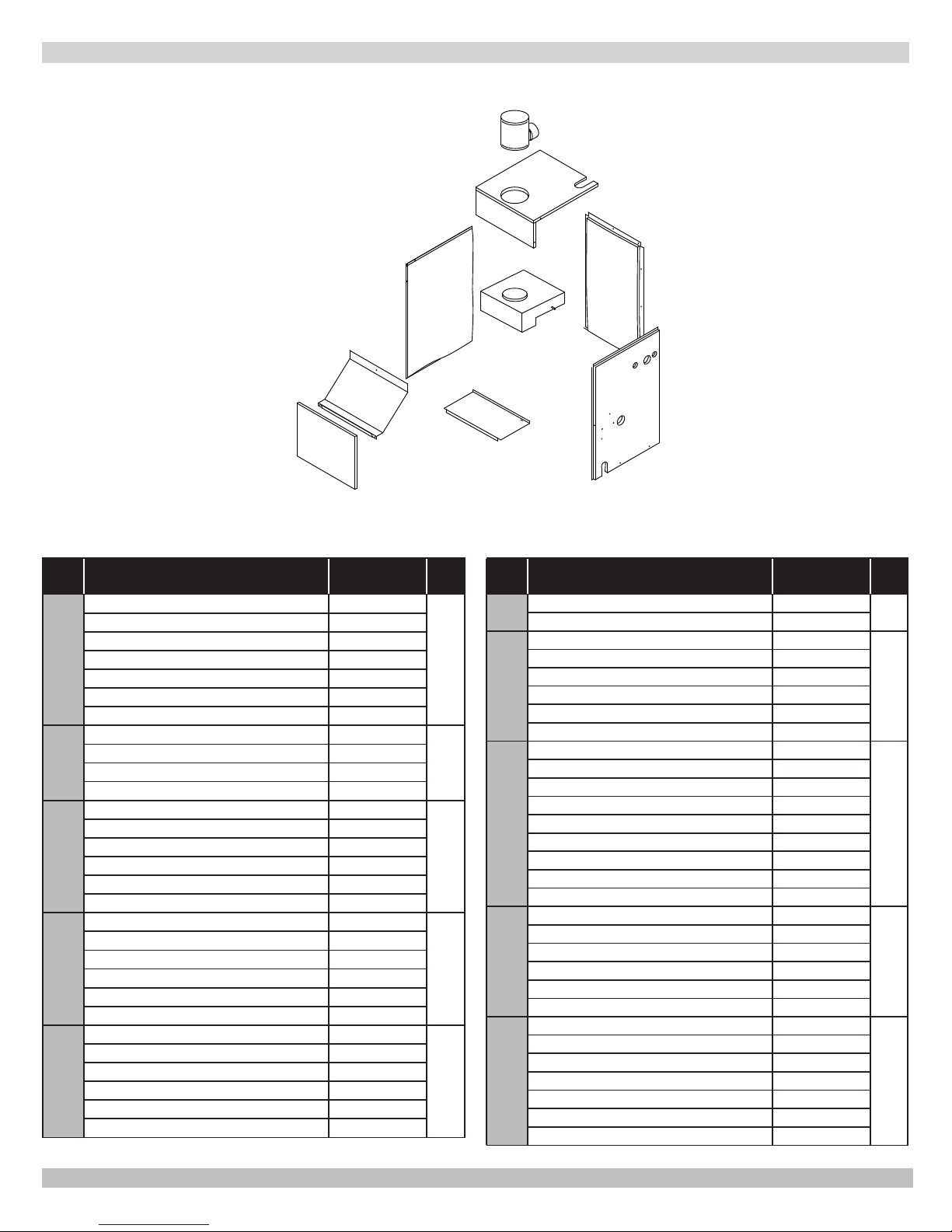
BOILER JACKET
REPLACEMENT PARTS - JACKET
Item
#
1
2
3
4
5
DESCRIPTION Part Number Qty.
PANEL - TOP 50 31621501
PANEL - TOP 75 & 100 31621502
PANEL - TOP 125 31621503
PANEL - TOP 150 31621504
PANEL - TOP 175 & 200 31621505
PANEL - TOP & 250 31621506
PANEL - TOP & 300 31621507
PANEL - LEFT 250-300 3162704
PANEL - LEFT (L)50-200 3162706
PANEL - LEFT (L)250-300 3162707
PANEL - LEFT 50-200 3162708
DRAFT DEFLECTOR 50 3162501
DRAFT DEFLECTOR 75/100 3162502
DRAFT DEFLECTOR 125/150 3162503
DRAFT DEFLECTOR 175/200 3162504
DRAFT DEFLECTOR 250 3162505
DRAFT DEFLECTOR 300 3162506
PNL LWR ACCES 50 109008534
PNL LWR ACCES 75/100 109008535
PNL LWR ACCES 125/150 109008536
PNL LWR ACCES 175/200 109008537
PNL LWR ACCES 250 109008538
PNL LWR ACCES 300 109008539
PANEL - BASE 50 3161201
PANEL - BASE 75 & 100 3161202
PANEL - BASE 125 & 150 109008530
PANEL - BASE 175 & 200 109008531
PANEL - BASE 250 109008532
PANEL - BASE 300 109008533
Item
#
PANEL - RIGHT 50-200 3162705
6
PANEL - RIGHT 225-300 3162703
PANEL - REAR 50 3162601
1
1
1
1
1
PANEL - REAR 75 & 100 3162602
PANEL - REAR 125 & 150 3162603
7
PANEL - REAR 175 & 200 3162604
PANEL - REAR 250 3162605
PANEL - REAR 300 3162606
FLUE COL 50 3462101
FLUE COL 75 3462108
FLUE COL 100 3462102
FLUE COL 125 3462107
8
FLUE COL 150 3462103
FLUE COL 175 3462109
FLUE COL 200 3462104
FLUE COL 250 109008527
FLUE COL 300 3462106
DAMPER 4" 50 240006936
DAMPER 5" 75 240006937
DAMPER 6" 100 & 125 240006938
9
DAMPER 7" 150 & 175 240006939
DAMPER 8" 200 & 250 240006940
DAMPER 9" 300 240006941
PNL- UPPER ACCESS 50 31621201
PNL- UPPER ACCESS 75&100 31621202
PNL- UPPER ACCESS 125 31621203
10
PNL- UPPER ACCESS 150 31621204
PNL- UPPER ACCESS 175 & 200 31621205
PNL- UPPER ACCESS 225 & 250 31621206
PNL- UPPER ACCESS 275 & 300 31621207
DESCRIPTION Part Number Qt y.
1
1
1
1
1
25
Page 26
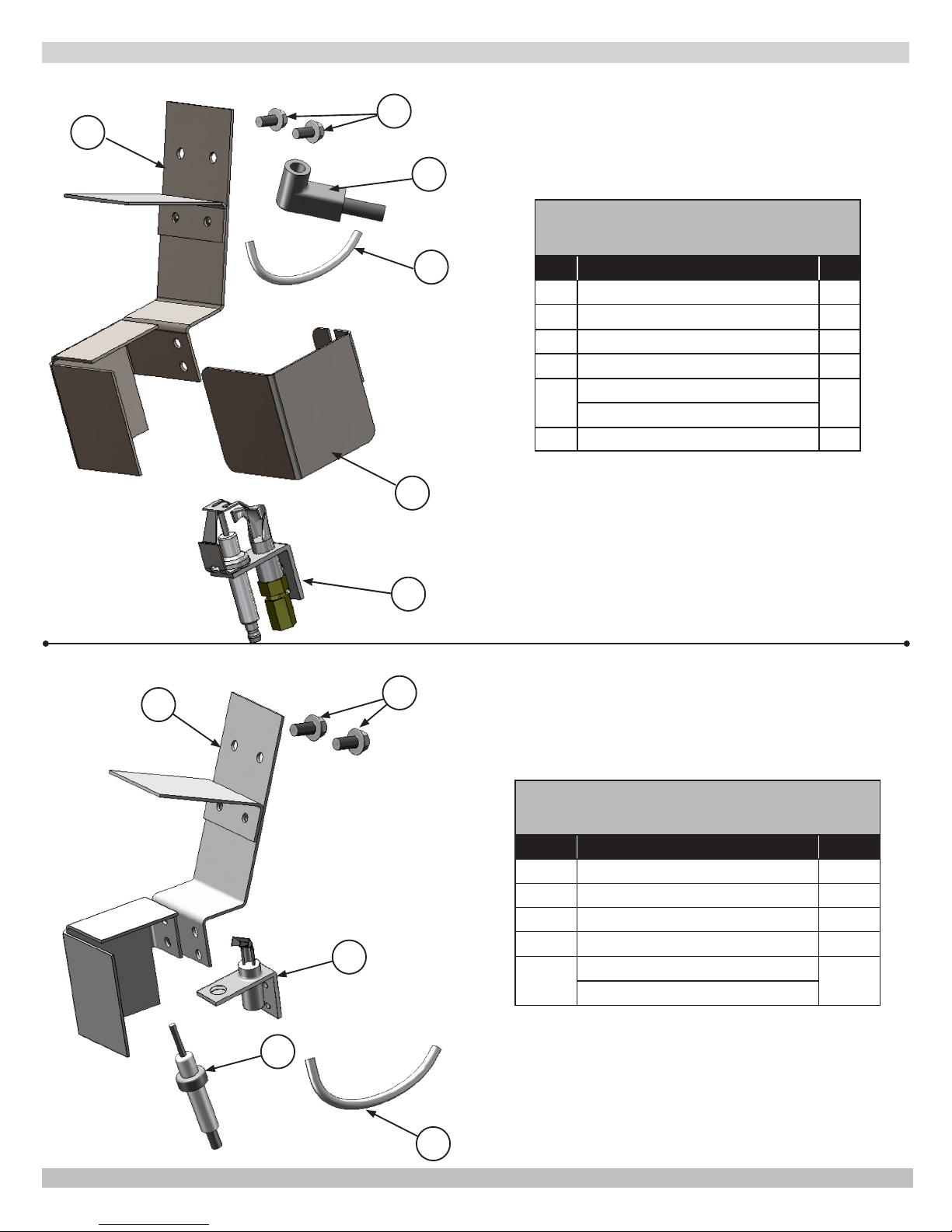
STANDING PILOT
1
REPLACEMENT PARTS - PILOT
2
3
Spark Pilot Kit - Natural Gas 550001911
Spark Pilot Kit - LP/Propane 550001912
CONTINUOUS PILOT
1
4
Item Description Qty.
1 PILOT BRACKET ASSEMBLY 1
2 BRACKET SCREW 2
3 SPARK CABLE 1
PILOT TUBING, 1/8" x 24"
4
Natural Gas Q345A PILOT
5
LP Q345A Pilot
6 Pilot Shield 1
* Included with #3 - Pilot Tube Assembly Kit (above)
1
1
5
6
2
3
Continuous Pilot Kit - Natural Gas 550001926
Continuous Pilot Kit - LP/Propane 550001927
Item Description Qty.
1 PILOT BRACKET ASSEMBLY 1
2 BRACKET SCREW 2
3 THERMOCOUPLE Q309 1
PILOT TUBING, 1/8" x 24"
5
4
Natural Gas Q314A PILOT
5
LP Q314A Pilot
* Included with #3 - Pilot Tube Assembly Kit (above)
1
1
4
26
Page 27
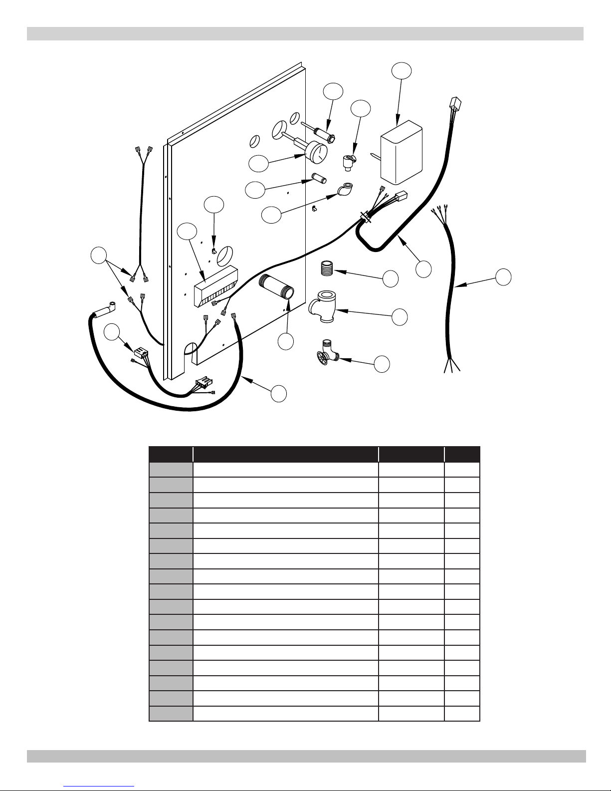
PIPING & CONTROLS
1
2
REPLACEMENT PARTS - PIPING & CONTROLS
12
11
13
14
16
15
17
4
10
7
8
9
6
5
3
ITEM DESCRIPTION P/N QTY.
1 WIRE ROLLOUT/SPILL 28" 37513301 2
2 HARNESS IGN TO G/V 18" 37413602 1
3 PILOT IGNITION CABLE 30" PB00702 1
4 PIPE - NPL 1.1/4X4.1/2 NPT PF-006.07 1
5 DRAIN - SHORT HW-016.03 1
6 PIPE - TEE 1.1/4X3/4X1.1/4 PF-008.03 1
7 PIPE - 1.1/4" CLOSE NPL PF-006.01 1
8 WIRE LOW VOLTAGE/DAMPER 375-1-14.01 1
9 HARNESS CIRCULATOR 72" 37519501 1
10 CONTROL L8148E1257 (AQUASTAT) 1010002 1
11 RELIEF VALVE 30# VR-001.01 1
12 WELL 3/4"X3" AQ-020.01 1
13 GAUGE - THERALTIMETER GA-001.00 1
14 PIPE - NPL 3/4"X4" PF-005.11 1
15 PIPE - ELBOW 3/4" 90° PF-002.04 1
16 CLAMP #3600 WHITE EF03601 2
17 PLT SPARK CTRL S8600 PB00604 1
27
Page 28

Columbia Company
Main ofces and factory
Pottstown, PA
 Loading...