

Columbia Delta-Q Operation
Delta-Q Automatic Charger Operation
Battery Charging Summary:
All current production Columbia 24/36/48 volt electric vehicles are bu ilt with a new solid state on-board, fully
automatic Delta Q Battery Charger as standard equipment. It is important to be aware of the differences and
improvements over prior chargers. This bulletin explains in more detail the Delta Q Charger Operating
Instructions that accompany every vehicle.
Always schedule enough charging time so the Delta Q Charger attains the 100% level, illuminates the 100%
Green LED, and automatically stops the charging cycle. Charging time is affected by age and battery condition,
state of discharge, electrolyte temperature, AC line voltage, and other variables.
extend battery life and vehicle range between charges. Before the first new vehicle use, completely charge new
batteries. Charging time will vary based on conditions noted above but will probably be 12 hours. New
batteries need up to four hours more charging than “mature” batteries.
Limit new batteries use between charges for the first 15-20 cycles. New batteries have less capacity than
seasoned batteries. New batteries should not be discharged more than 20-30% before recharging. This practice
prevents premature battery failure.
The AC power Yellow LED should remain illuminated while the charger is plugged into an AC source. If
charger does not power up, after following the instructions described in step 1, then contact your Columbia
Dealer for assistance.
Do Not Disassemble the Charger. There are No Serviceable Components.
Charger Operating Instructions:
1. Connect power cord at charger receptacle to proper grounded wall outlet.
Note: The AC cord to each charger is to be connected to a source capable of supplying 15 amperes minimum
per charger (20 amperes recommended). The charger is equipped with an equipment-grounding AC electric
cord, and a grounding type plug. Connect the cord to an appropriately installed receptacle grounded in
accordance with the National Electric Code ANSI/NFPA 70, and all local codes and ordinances.
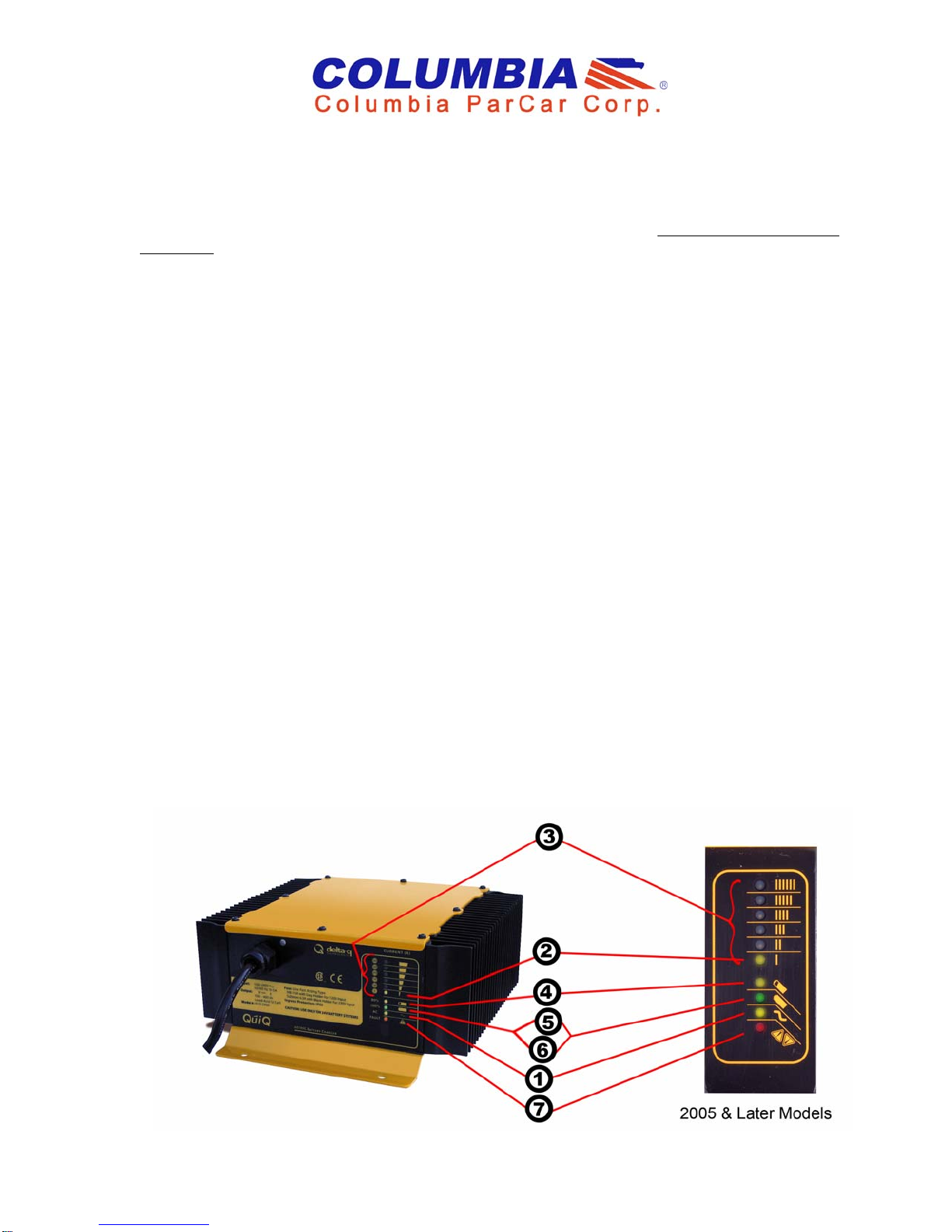
The Yellow AC power LED [(1) in figure below] should remain illuminated while the charger is plugged into
an AC source. If the Yellow LED [(1)] is not lit, before replacing charger inspect and confirm the two AC
connections supplying the charger on the vehicle are intact. First is the extension cord receptacle, typically
found behind the left leg of the driver on the vehicle’s body. Second is the three pronged quick connection on
the short 6” AC cord extending from the LED panel. Also confirm your AC source fuse or breaker operation,
then contact your Columbia Dealer for assistance.
Correct charging methods
1
719465
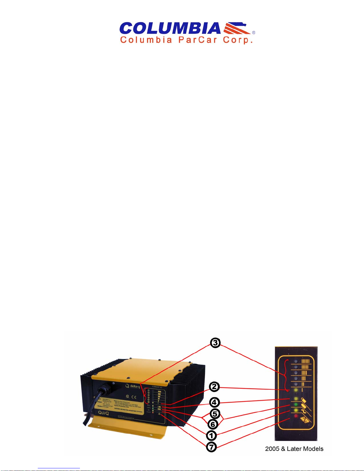
2. Charger will automatically turn on and conduct a short self-test and battery pack test. All LED’s will flash
in sequence, then a trickle current will be applied to batteries until a minimum voltage is reached. Three (3)
amperes is displayed as the lowest LED on the Bar Graph. See (2) in figure below.
3. If the batteries meet the minimum voltage requirements of the Charger, signifying they are serviceable
(chargeable), the Charger enters the bulk charging (higher amperage-constant current) stage.
The Current (A) Bar Graph LED’s, (3) in figure below, indicates the electrical current delivered to the batteries
as the charger moves through its automatic charge profile. The length of charge time at each level will vary due
to battery size and battery charge depletion.
Note: If the Charger only reaches the trickle stage, (2) in figure below, and does not enter the higher rate
Current (A) Bar Graph region with a steady LED lit, the batteries may be excessively discharged, and not
capable of automatic charge with the Delta-Q. The Charger may time-out with a Red Fault LED, (7) in figure
below. (Flash Code Faults - See Red Light Charger Error Code below.). It will then be necessary to follow the
Special Charging Procedure summarized at end of this bulletin, and also outlined in the Battery CareMaintenance Procedures Section of your Owners Manual.
4. When the yellow 80% LED is lit, the Charger has completed the bulk stage and the batteries are at
approximately 80% state of charge. The 80% LED remains on as the last 20% of charged is returned to the
batteries in the second phase (constant voltage phase). (4) in figure below.
Note: You can terminate charging at this point if necessary. The vehicle can be used, but completing the charge
cycle is highly recommended, until the 100% Green LED is lit, see No. 5&6. Repeated “Short Charging,”
leaving the charge short of 100%, will shorten operating cycle distance and run-time and reduce battery life.
5. A low current “finish-charge” phase returns and maintains batteries to maximum capacity. The Green LED
will blink until “finish-charge” phase is complete. On vehicles equipped with a Battery Discharge Indicator
(BDI), the Red LED display on the dash mounted meter scrolls across from right to left during the finish charge
and is normal operation.
6. A Green LED continuously lit, indicates the batteries are completely charged. The Charger may now be
unplugged from the AC source. (6) in figure below. If the vehicle is not operated for a length of time, see the
appropriate Section “Storing Your Vehicle,” and maintaining the batteries charge level.
7. A fault occurring while charging causes the RED FAULT LED to flash with a code relaying the error. Some
errors may require repair by a qualified technician and others may be simply transient and will automatically
recover when the fault condition is eliminated and the Delta Q cycled by disconnecting the AC source a
minimum 11 seconds. (7) in figure below, and Red Light Charger Error Codes.
Note: A Yellow (Amber) Blinking LED (Region 3 in figure below) in the Bar Graph usually indicates the
thermostatic control has limited the Charger output due to ambient temperature conditions. It is still charging,
but at a reduced rate.
2
719465
 Loading...