

Columbia CWH-170, CWH-240, CWH-300, CWH-390, CWH-475 Installation, Operation And Maintenance Manual
...
L
•
WL
•
CWH SERIES
BOILERS
INSTALLATION,
OPERATION and
MAINTENANCE MANUAL
COLUMBIA BOILER COMPANY
P.O. BOX 1070, POTTSTOWN, PA 19464
PHONE: 610-323-2700 • FAX: 610-323-7292
www.columbiaboiler.com
COLUMBIA


Table Of Contents
PARTS WARRANTY . . . . . . . . . . . . . . . . . . . . . . . . . . . . . . . . . . . . . . . . . . . . . . . . . . . . . . . . . . . . .2
INTRODUCTION . . . . . . . . . . . . . . . . . . . . . . . . . . . . . . . . . . . . . . . . . . . . . . . . . . . . . . . . . . . . . . .3
SERVICE POLICY . . . . . . . . . . . . . . . . . . . . . . . . . . . . . . . . . . . . . . . . . . . . . . . . . . . . . . . . . . . . . .4
INSTALLATION . . . . . . . . . . . . . . . . . . . . . . . . . . . . . . . . . . . . . . . . . . . . . . . . . . . . . . . . . . . . . . . . .5
BOILER ROOM . . . . . . . . . . . . . . . . . . . . . . . . . . . . . . . . . . . . . . . . . . . . . . . . . . . . . . . . . . .5
VENTING . . . . . . . . . . . . . . . . . . . . . . . . . . . . . . . . . . . . . . . . . . . . . . . . . . . . . . . . . . . . . . . .5
JACKET ASSEMBLY . . . . . . . . . . . . . . . . . . . . . . . . . . . . . . . . . . . . . . . . . . . . . . . . . . . . . . .6
BURNER MOUNTING . . . . . . . . . . . . . . . . . . . . . . . . . . . . . . . . . . . . . . . . . . . . . . . . . . . . . .7
BOILER CONNECTIONS . . . . . . . . . . . . . . . . . . . . . . . . . . . . . . . . . . . . . . . . . . . . . . . . . . .8
FUEL CONNECTIONS . . . . . . . . . . . . . . . . . . . . . . . . . . . . . . . . . . . . . . . . . . . . . . . . . . . .11
CLEANING AND FILLING A NEW STEAM BOILER . . . . . . . . . . . . . . . . . . . . . . . . . . . . . . . . . . .16
OPERATING THE BOILER . . . . . . . . . . . . . . . . . . . . . . . . . . . . . . . . . . . . . . . . . . . . . . . . . . . . . . .18
STARTING THE BOILER . . . . . . . . . . . . . . . . . . . . . . . . . . . . . . . . . . . . . . . . . . . . . . . . . .19
STOPPING THE BOILER . . . . . . . . . . . . . . . . . . . . . . . . . . . . . . . . . . . . . . . . . . . . . . . . . 19
BURNER START UP AND TEST INFORMATION . . . . . . . . . . . . . . . . . . . . . . . . . . . . . . . . 20
CONTROL DESCRIPTIONS . . . . . . . . . . . . . . . . . . . . . . . . . . . . . . . . . . . . . . . . . . . . . . . . 21
MAINTENANCE . . . . . . . . . . . . . . . . . . . . . . . . . . . . . . . . . . . . . . . . . . . . . . . . . . . . . . . . . . . . . . 24
Daily Boiler Check & Maintenance List . . . . . . . . . . . . . . . . . . . . . . . . . . . . . . . . . . . . . . . 24
Monthly Boiler Check & Maintenance List . . . . . . . . . . . . . . . . . . . . . . . . . . . . . . . . . . . . 25
Semiannual Boiler Check & Maintenance List . . . . . . . . . . . . . . . . . . . . . . . . . . . . . . . . . . 25
Annual Boiler Check & Maintenance List . . . . . . . . . . . . . . . . . . . . . . . . . . . . . . . . . . . . . .25
WATER TREATMENT . . . . . . . . . . . . . . . . . . . . . . . . . . . . . . . . . . . . . . . . . . . . . . . . . . . . . . . . . . .27
APPENDICES . . . . . . . . . . . . . . . . . . . . . . . . . . . . . . . . . . . . . . . . . . . . . . . . . . . . . . . . . . . . . . . . .30
Recirculation; Twin Units and Tank Systems
Specifications and Data - L Series; WL Series; CWH Series
Replacement Parts List for L, WL & CWH Series Boilers
Burks Turbine Pumps - Impeller Adjustment Instructions
Piping Layout Dwgs. PL-100, PL-101, PL-099, PL-102
Corning Tubular Gage Glasses, Red Line - Use, Care and Installation
Warrick Probe Series 26 Controls
Warrick Probe Assembly - Replacement Parts
Safety Valve Piping, Typical
McDonnell & Miller Installation & Maintenance Instructions (one or more):
MM-201(B) Series 767 Low Water Cut-Offs for Steam Boilers
MM-213(C) Series 750 Probe Type Low Water Cut-Offs with Remote Sensors
MM-231 Series 42 Low Water Cut-Off/Pump Controller
MM-316 Series 247-2 Combination Mechanical Water Feeder/Low Water Cut-Off
Pressure Control Bulletin (steam units only)
Honeywell Aquastat Controllers L4006 IOM Bulletin

LWLCWH COLUMBIA BOILER COMPANY REV. 3107
1
IMPORTANT
1. Read and familiarize yourself with this installation, operation, and
maintenance manual before installing, operating, or servicing your
boiler.
2. All cover plates, enclosures, and safety devices must be installed
at all times except while performing maintenance and service.
3. Only trained service technicians should do any work on your
boiler.
4. All state and local codes take precedence over any
recommendations given in this manual.
LWLCWH COLUMBIA BOILER COMPANY REV. 13106
2
LIMITED PARTS WARRANTY
The Columbia Boiler Company (hereinafter Columbia) warrants the burner components and controls installed on its boiler/burner units to be free from defects in material and workmanship under normal use and service for 12 months from the date of
installation or 18 months from the date of manufacture, whichever date occurs first and
is subject to warranty approval by the manufacturer of the specific components. This
warranty does not extend to equipment subjected to misuse, neglect, accident or
improper installation. Equipment which is defective in material or workmanship and is
removed within 12 months from the date of installation will be repaired or replaced as
follows:
(a) Motors, fuel units, controls, and transformers should be sent for repair or
replacement to an authorized service point or distributor of the manufacturer of
such component when reasonably available in Customer’s locality.
(b) Where such local service is not available with respect to the above listed compo-
nents, or where other components are involved, such defective equipment
should be returned after receiving authorization from your dealer, freight prepaid, to the Columbia Boiler Co., 390 Old Reading Pike, Pottstown PA 19464.
The use of the Columbia returned goods form is mandatory when returning
defective material.
(c) Columbia is not responsible for any labor cost for the removal and replacement
of equipment.
(d) Equipment which is repaired or replaced will carry a warranty equal to the unex-
pired portion of the original equipment warranty.
(e) If inspection by Columbia does not disclose any defect covered by this warran-
ty, the equipment will be repaired or replaced at the expense of the Customer,
and Columbia’s regular charges will apply.
THIS WARRANTY IS LIMITED TO THE PRECISE TERMS SET FORTH
ABOVE, AND PROVIDES EXCLUSIVE REMEDIES EXPRESSLY IN LIEU OF
ALL OTHER REMEDIES. ALL IMPLIED WARRANTIES, INCLUDING BUT
NOT LIMITED TO ANY IMPLIED WARRANTY OF MERCHANTABILITY OR
FITNESS FOR A PARTICULAR PURPOSE OR USE, ARE EXCLUDED. IN NO
EVENT WILL COLUMBIA BOILER CO. BE LIABLE FOR ANY INCIDENTAL
OR CONSEQUENTIAL DAMAGES OF ANY NA TURE. Columbia neither assumes
nor authorizes any person to assume for Columbia any other liability or obligation in
connections with the sale of this equipment. Columbia’s liability and Customer’s exclusive remedy being limited to repairs or replacement as set forth above.
March 10, 1997

LWLCWH COLUMBIA BOILER COMPANY REV. 13106
3
INTRODUCTION
Series L and WL Water Tube Boilers
The Columbia Models L and WL are water tube boilers designed for hot water, and/or low pressure
steam applications. These units are manufactured to the specifications set forth by Section IV of the
ASME Boiler and Pressure Vessel Code. Boilers are inspected and stamped for conformity to requirements of the National Board of Boiler and Pressure Vessel Inspectors. All boilers are designed to be
fired using No. 2 fuel oil, and/or natural, manufactured, or liquid propane (LP) gas, and are powered
by standard AC electrical service.
CWH Series Steam Boiler
The CWH Series is a steam boiler used for indirect hot water applications. This boiler classification
consists of all L and WL Series Boilers providing heat transfer to one or two coils, depending on boiler size. The boiler is a self contained unit allowing a steam cavity above the water line for expansion.
Columbia hot water and low pressure steam boilers are typically shipped knocked down (unassembled), but are also available factory packaged. All boilers are furnished with a jacket kit, burner, and
boiler trim. Boiler trim consists of the operating and limit controls, pump and/or low water cut off
(LWCO) controls, a safety valve, and a smokehood for all WL Series Boiler Models, and Model L-32.
Factory packaged boilers are fully assembled and test fired.

LWLCWH COLUMBIA BOILER COMPANY REV. 13106
4
SERVICE POLICY
Anything mechanical will inevitably need servicing. Steam and hot water boilers are
routinely serviced by the installer or another boiler maintenance company. Occasionally
the service technician may be unable to determine the cause of the problem. In this situation, the dealer or service organization should contact the selling distributor for help.
Should the problem persist, the distributor will contact the sales representative for
assistance. Depending on the extent of the problem, the representative may request
technical assistance from the factory.
If the problem cannot be resolved by the representative, he should contact the
Technical Service/Engineering Department at the factory. The sales representative will
need the following information. It is essential that this information be available to assure
prompt service.
Boiler Model and Size (HP)_____________________________________________________
Boiler Serial Number __________________________________________________________
Boiler National Board Number _________________________________________________
Date Installed ________________________________________________________________
Burner Type and Model ________________________________________________________
Primary Burner Control Type ______________________________________________
Installer’s Name ______________________________ Phone (____)____________________
Address ____________________________________________________________________
Distributors Name ___________________________ Phone (____)_____________________
Address _____________________________________________________________________
Sales Representative _________________________ Phone (____)_____________________
Address ____________________________________________________________________
Specific Problem - Detailed

LWLCWH COLUMBIA BOILER COMPANY REV. 13106
5
INSTALLATION
BEFORE BEGINNING INSTALLATION, CAREFULLY STUDY THESE
INSTRUCTIONS AND ALL CHARTS, DRAWINGS, AND DIAGRAMS
SHIPPED WITH THE BOILER.
Installation must follow all state and local code requirements, Fire and Underwriters regulations, and
standard plumbing practices. The electrical installation shall be in accordance with the National
Electrical Code.
Remove all boiler components from packaging and inspect prior to assembly to ensure that damage
has not occurred in shipping.
BOILER ROOM
Locate the boiler in a well lit area on a noncombustible, level floor. Make available a convenient water
supply and allow adequate drainage, including unobstructed floor drains, for flushing and filling the
boiler. Provide sufficient make-up air for combustion at all times. Power the boiler using a properly
rated electrical service. Include fused disconnects for control circuits, blower motor circuits, and feed
pump circuits that require a motor contactor or motor starter relay.
Where possible, place the boiler on a 3 inch concrete pad. Allow adequate clearance between the
boiler and any walls or obstructions to permit inspection and service on burner , boiler piping, contr ols,
or combustion vent.
DO NOT install exhaust fans in or near the boiler room. Exhaust fans steal available make-up air during burner operation; and more importantly, when the boiler cycles off, exhaust fans pull hot flue
gases back through the burner causing burner parts to deteriorate, and to eventually fail prematurely. Maintain a positive pressure in the boiler room at all times.
Do not allow your boiler room to become a storage room.
VENTING
All Columbia boiler models utilize a pressure fired burner and need only to be properly vented. For
situations where unusual conditions may exist, consult the factory for proper venting.
Locate the boiler as close as possible to the chimney or other approved exhaust vent. For boiler models with a rectangular flue outlet, first bolt the supplied smokehood in place. Attach all flue piping to
the round flue connection and make each connection secure. The flue pipe should not be inserted
beyond the inside wall of the chimney.
DO NOT REDUCE THE SIZE OF THE FLUE OUTLET OR FLUE PIPING.
Columbia Boiler recommends the use of galvanized B Type vent for stack connections suitable for
temperatures to 550F. The flue pipe should be pitched upward at least 1/4” per foot of run. Avoid the
use of tees, sharp bends, and long horizontal runs. Install a draft regulator if required.
LWLCWH COLUMBIA BOILER COMPANY REV. 13106
6
COLUMBIA BOILER COMPANY OF POTTSTOWN SHALL NOT BE HELD LIABLE FOR DAMAGE
TO THE BOILER CAUSED BY INCORRECT VENT CONDITIONS AND/OR INSUFFICIENT BURNER MAKEUP AIR.
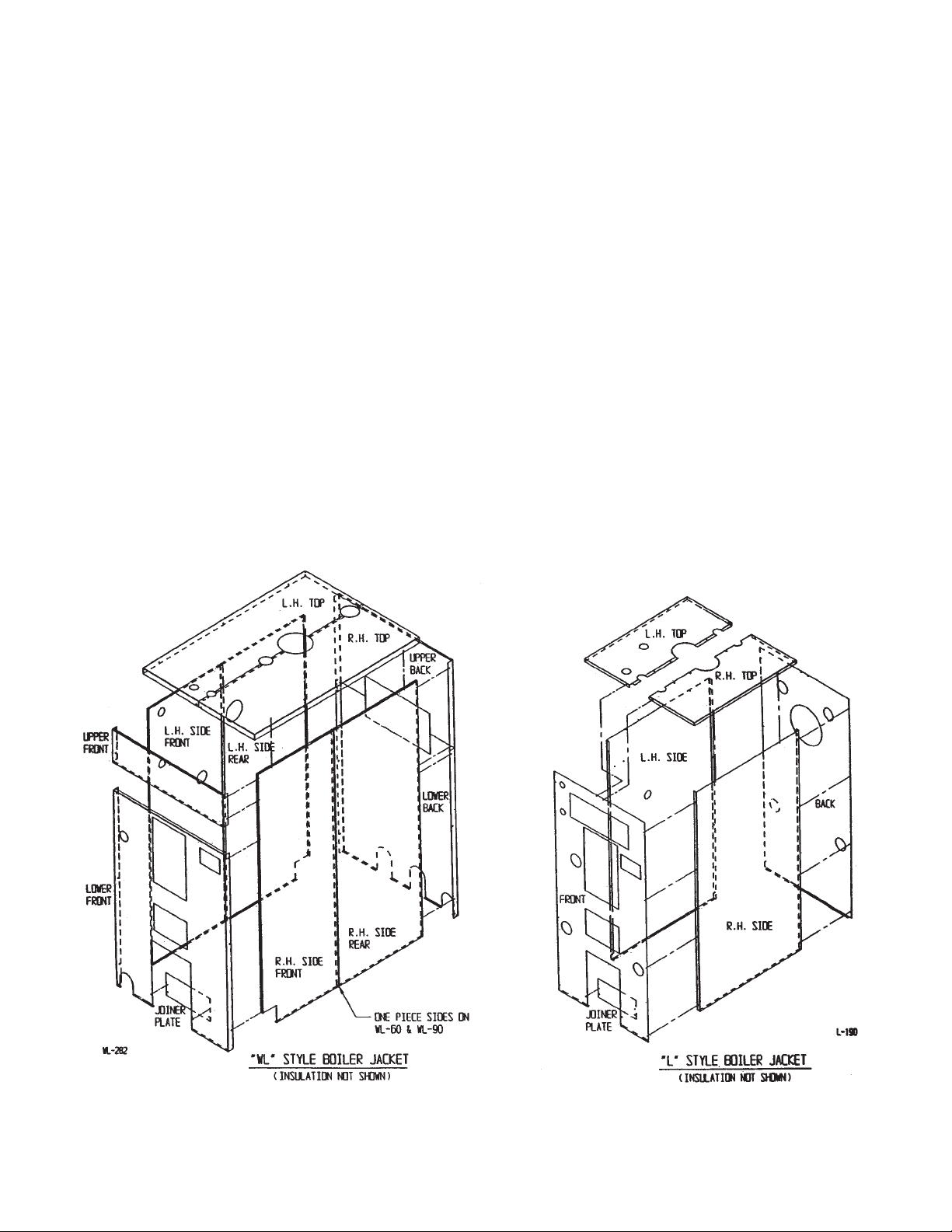
JACKET ASSEMBLY
Assemble the jacket kit around the boiler as shown in Figure 1. Place each panel against its respective side of the boiler.
NOTE: The side panels for boiler Models WL-120, WL-140 and WL-180 are two piece side
walls. Assemble these side wall pieces together before proceeding with jacket
installation.
Assemble the lower front panel to one side wall at a time. Next, attach the lower rear panel to each
side wall of the boiler. When applicable, mount the upper front and rear panels in their respective
locations. Attach the joiner plate behind the lower portion of the lower front panel as shown. Finally,
assemble the top right and left jacket panels on top of the boiler. Attach these panels to the previously assembled jacket components. If necessary , pr epipe the top of the boiler befor e assembling the
top jacket panels. The top jacket panels are designed to allow prepiping to the top center boiler fittings, if needed.
Figure 1
LWLCWH COLUMBIA BOILER COMPANY REV. 13106
7
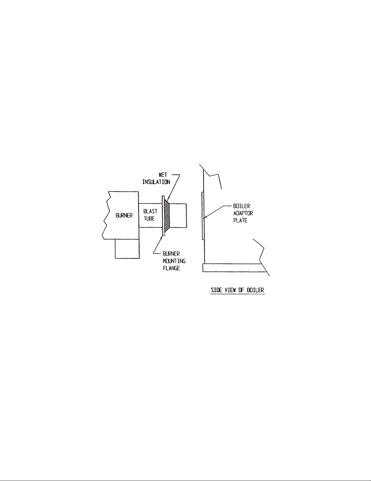
BURNER MOUNTING
If the burner is to be installed on site, first apply a gasketing material between the burner flange and
the burner mounting plate to seal the burner . Use a non-asbestos fiber rope, or a wet insulating material for a gasket, as shown in Figure 2. Wet insulation is the preferred gasketing material because it
compresses into a flat gasket which conforms to and fills any and all voids. Secure the burner in the
boiler using the four bolts supplied with the burner. See the Burner Section of this manual for proper
electrical wiring, and fuel supply piping.
Note: All factory packaged boilers use a wet insulation material as a gasket.
Figure 2

LWLCWH COLUMBIA BOILER COMPANY REV. 13106
8
BOILER CONNECTIONS
Drains
All Columbia Boiler units have (4) washouts located around the lower corners of the boiler for drainage
purposes. Install a pipe nipple and ball valve in a least one washout for use as a drain. If a washout
is not needed, plug it by using the proper size nipple and a pipe cap. DO NOT use a pipe plug.
Low Water Cut-Offs
All Columbia boilers are supplied with a single low water cut-off (LWCO) as standard equipment.
Several boiler applications may require a secondary LWCO. The standard equipment is as follows:
Hot Water Boilers - McDonnell & Miller 750-MT-120 Probe Type Low Water Cut-Off with Remote
Sensor - Thread the Remote Sensor into the 3/4” NPT fitting located on top of the boiler. Mount the
Control Box near the top of the front jacket panel (or upper front jacket panel on some units).
Steam Boilers - McDonnell & Miller Model 767 Quick-Hook-Up Low Water Cut-Off - Install this device
into the 2-1/2” NPT welded coupling found on the coil plate for L Series boilers, and on the left hand
side of the heat exchanger for WL Series boilers.
Water Heaters - McDonnell & Miller Model 767 Quick-Hook-Up Low Water Cut-Off- Install this device
into the 2-1/2” NPT welded coupling found on the coil plate for CWH-170 / -610 Series boilers, and
on the left hand side of the heat exchanger for CWH-780 / -2460 Series boilers.
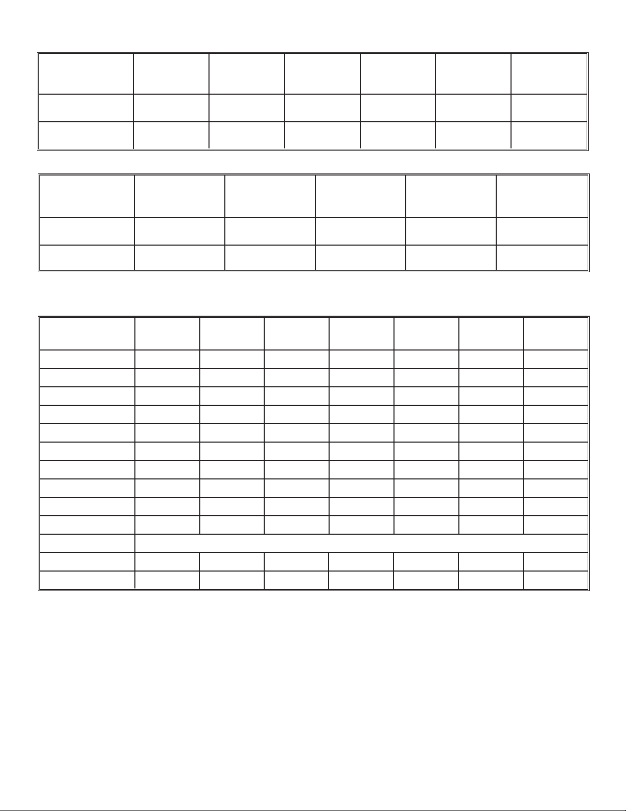
Secondary Low Water Cut-Offs
Secondary LWCO s may be r equir ed to meet local codes or CSD-1 requir ements. A W arrick 26C1C1C
Probe Type Low Water Cut-Off is used in steam applications to meet CSD-1 requirements. Thread the
remote sensor into the 1/2" NPT fitting located on top of the boiler using a 1/2" x 3/8" bushing. See
Table 1. for proper probe rod length. Mount the control box to a front or side jacket panel on the
boiler.
LENGTH OF PROBE ROD IN “L” AND UP TO” CWH-610” SERIES BOILERS
BOILER L-18 L-20 L-22 L-24 L-30 L-32
MODEL CWH-170 CWH-240 CWH-300 CWH-390 CWH-475 CWH-610
ROD LENGTH 4-7/8" 6-1/4" 6-1/4" 6-1/4" 7" 9-5/8"
Table 1a

LWLCWH COLUMBIA BOILER COMPANY REV. 13106
9
LENGTH OF PROBE ROD IN “WL” AND UP TO” CWH-780 & UP” SERIES BOILERS
BOILER WL-60 WL-90 WL-120 WL-140 WL-180
MODEL CWH-780 CWH-1200 CWH-1510 CWH-1810 CWH-2460
ROD LENGTH 14-1/2" 14-1/2" 14-1/2" 14-1/2" 14-1/2"
Table 1b
Other secondary LWCO s include combination LWCO / Water Feeders. These devices are typically
connected externally using an equalizing line, and piped into the available 1" NPT fittings found in
boiler top, and left side or front. Most commonly used combination units are McDonnell & Miller 42
Series Pump Controls and Low Water Cut-Off or McDonnell & Miller No. 247-2 Feeder Combination.
For piping diagram, see the List of Figures on the Table of Contents Page of this manual.
NOTE: Mount a combination unit so the low water cut-off line on the device is approximately 3
inches above the lowest permissible water level plate found on the left side jacket panel of
he boiler.
Water Gauge
The water gauge is piped into the (2) 1/2" NPT fittings located in the left side of the boiler . During operation, the boiler s water level should always be above the Lowest Permissible Water Level indicator
label found on the left side jacket panel of the boiler. Hot water boilers do not require a Water Gauge.
Pressure Controls
Low pressure, 15 PSI controls are supplied with steam units only. These controls consist of an
Operating Control and a Safety Limit. An additional operating control may also be supplied for burners that function with low-high-low operation. Pipe the Pressure Control and the 30 PSI Steam Gauge
using the supplied steam syphons. See Drawing PL-099 in the Appendix.
The Pressure Control must be level in order to operate accurately. A Pressure Control is level when
the leveling indicator hangs freely with its pointer directly over the index mark, inside the back cover
of the case.
Aquastat Controllers
®
Aquastat Controllers are used to regulate boiler water temperature. Columbia supplies an Operating
Control (Honeywell L4006A Aquastat
®
) and a Safety Limit (Honeywell L4006E Aquastat®) with all hot
water boilers and water heaters. An additional Operating Aquastat
®
may also be supplied for burners
that function with low-high-low operation or steam boilers using an optional coil. Aquastat®’s are
mounted in the 3/4" NPT fittings located on the coil plate on the front of the boiler.

LWLCWH COLUMBIA BOILER COMPANY REV. 13106
10
Safety Valve / Relief Valve
All safety or relief valves are located in the rear center fitting on top of the boiler. A 15 PSI Steam
Safety Valve is supplied for steam boiler and water heater applications. A 30 PSI Water Relief Valve is
used for hot water applications. All safety and relief valves should be safely piped away from the boiler without reducing the valve s outlet port size.
Steam Supply
Pipe the steam lines to the largest fitting or flange located on top of the boiler.
Note: For CWH UNITS ONLY - Plug the main steam outlet unless an expansion tank is used.
Hot Water Supply
Use the fitting/pipe flange on the top of the boiler for the hot water supply to the system. Hot water
applications also require the use of an expansion tank in the supply piping, to compensate for fluctuations in the water volume during heating and cooling cycles.
Feed Water Supply
Virtually any unused port on the heat exchanger can be used for the feed water supply, including any
unused drain port. In situations where make up water is needed, the water supply must be treated
before it enters the boiler, to prevent the formation of scale, or to protect the boiler surfaces from the
corrosive effects of oxygenated water. Water treatment and a water treatment program must be practiced, or the life of the boiler will be severely limited. If a Condensate Return / Feedwater Tank is used,
connect the feedwater source to the float valve on the tank.
Coils
Boilers are shipped with the coil(s) assembled to the coil plate(s), and mounted in the boiler. For the
smaller L-Series, L-18(CWH-170) thru L-24(CWH-390), the coil plates cover the opening for which the
coils pass through. The indirect water inlet and outlet connections are made in the rear of the boiler.
All other Columbia models can be furnished with one or two coils. CWH models larger than a CWH390 always have two coils.
When making coil connections for twin coil units, manifold indirect water piping using copper tubing
and fittings connected in parallel. Pipe the outside coil openings together for cold water inlets, and
the inside coil openings for hot water outlets. If necessary, temper the hot water supply by using a
mixing valve. Connect the hot water outlet source and a cold water supply line to a mixing valve, to
temper the hot water supply to the proper temperature requirements for process equipment.
Whenever boilers are supplied with one or two coils, the coils must be covered by a minimum of two
inches of water, during normal operation, to allow proper heat transfer through the coil. Adjust all
LWCO piping to keep the coil(s) submerged in the event of a low water situation.

LWLCWH COLUMBIA BOILER COMPANY REV. 13106
11
FUEL CONNECTIONS
OIL SUPPLY PIPING
Connect burner to oil supply . Refer to fuel unit manufacturer literatur e for piping, connections, lift and
tank installation. If such information is unavailable use the following guidelines:
Fuel supply “level with” or “above” burner: A single stage fuel unit connected to the fuel supply
with a single supply line is the most common type of installation for these conditions. Manual venting of the fuel oil is usually required on initial start up. Failure to vent air could r esult in air lock/oil starvation.(One Pipe)
Fuel supply below the level of the burner: Use a single stage fuel pump in lift conditions of up to
10 feet and a two stage pump when lift exceeds 10 feet. Both conditions require the use of a return
line which purges the fuel pump of air, returning it to the fuel tank. The by-pass plug must be inserted into the fuel pump when installing a return line.(Two Pipe)
Fuel line installation: Consult the burner section of this manual for oil line type and sizing requirements for proper operation. The size of oil lines is extremely important for proper operation.
Continuous lengths of heavy wall copper tubing are recommended and should be installed under the
floor whenever possible. Fuel lines should not chaff the appliance or building structure.
All oil feed lines must be air tight. Use as few fittings as possible when assembling the oil lines.
Compression fittings allow more of a chance for air to be introduced into the oil supply. The slightest
air leak, usually caused by loose fittings or bad gaskets, can cause poor starts, smoky starts, sooting of burner parts, inefficient operation, and a dangerous combustion condition. Always install fittings
in accessible locations.
WARNING:
TEFLON
®
TAPE SHOULD NEVER BE USED WITH ANY OIL LINE CONNECTIONS.
THE USE OF TEFLON®TAPE ON BURNER COMPONENTS OR OIL SERVICE LINES
WILL VOID MOST BURNER WARRANTIES.
A vacuum test should be done on all installations to ensure that all fittings are tight and the oil lines
are of proper size. Suction vacuums must be held to acceptable limits.
Fuel line valve and filter: (Not supplied) Install two high quality shutoff valves in accessible locations
on the oil supply line. Locate one close to the tank and the other close to the burner ahead of the filter. Some filters come with built-in shutoff valves. Install a generous capacity filter inside the building
between the fuel tank shutoff and burner.
For additional information consult the burner section of this manual.

LWLCWH COLUMBIA BOILER COMPANY REV. 13106
12
GAS SUPPLY PIPING
Contact your local gas company to ensure that adequate gas service is available, and to review applicable installation codes for your area.
The minimum gas supply pressure required by the bur ner is five inches water column for the GL-18,
GL-20, GL-22, GL-24, CWH-170, CWH-240, CWH-300, CWH-390 and seven inches water column for
the GL-30, GL-32, CWH-470, CWH-610, CWH-780, CWH-1200 CWH-1510, CWH-1810, CWH-2460
and all WL Series boilers. The maximum gas supply pressure to the burner is fourteen inches water
column. Gas pressure greater than fourteen inches water column will require an additional gas pressure regulator to prevent damage to the primary gas regulator. Gas pressure below the minimum will
cause combustion efficiency problems and should be avoided if possible. Low gas pressur e may also
prevent the boiler from obtaining the desired input rate, which will cause the boiler to be unable to
produce the desired output. Consult the factory if your gas supply pressure is not in the recommended range.
Use the following tables to determine the size of the main gas line required for the boiler that is being
installed. First determine the required input volume of gas needed at the gas manifold, then determine the correct pipe size for the length of run needed.
LWLCWH COLUMBIA BOILER COMPANY REV. 13106
13
REQUIRED INPUT - CUBIC FEET OF GAS PER HOUR
L-18 L-20 L-22 L-24 L-30 L-32
CWH-170 CWH-240 CWH-300 CWH-390 CWH-475 CWH-610
NATURAL 168 252 336 420 560 700
PROPANE 67 101 134 168 224 280
WL-60 WL-90 WL-120 WL-140 WL-180
CWH-780 CWH-1200 CWH-1510 CWH-1810 CWH-2460
ROD LENGTH 840 1260 1680 1960 2520
PROPANE 336 504 672 784 1008
CAPACITY OF PIPE - CUBIC FEET OF GAS PER HOUR AT 0.2" W.C. PRESSURE DROP
Equivalent
1" 1-1/4" 1-1/2" 2" 2-1/2" 3" 4"
Length (ft)
10 425 725 1170 2360 4300 6250 12800
20 300 520 800 1700 3000 4500 9300
30 250 425 690 1400 2500 3750 7500
40 210 360 560 1200 2100 3200 6400
50 190 325 500 1100 1900 2850 5800
60 180 300 480 1000 1800 2300 4800
80 150 260 410 850 1550 2000 4200
100 135 230 370 750 1375 1680 3500
150 110 190 300 600 1100 1200 2750
200 75 165 260 540 950 1000 2000
Fitting Equivalent Lengths of Standard Pipe in Feet for Listed Fittings
Std. Tee 5.5 7.5 9.0 12.0 13.5 15 20
Std. Elbow 2.7 3.7 4.5 5.5 6.1 8 11
Vent lines, if r equired, ar e to be run outside the building, stopping clear of windows or fresh air intakes.
The vent should terminate in a way that will not allow the possibility of water, dirt, insects, animals,
and other matter from entering and clogging the vent pipe.
GAS TYPE
GAS TYPE

LWLCWH COLUMBIA BOILER COMPANY REV. 13106
14
Gas lines should be tested for leaks. Your gas company may wish to witness this test. Do not exceed
the maximum pressures allowed by the valve train.
Additional gas piping information is included in the burner section of this manual.
COMBUSTION AIR
It is essential that provisions are made for a fresh supply of outside air into the boiler room to insure
complete combustion, proper boiler efficiency, and a clean fire. Sufficient makeup air also helps prevent nuisance shut-downs due to excessive combustion byproduct build-up on burner parts. Outside
air may be provided through ducts, fixed louvers or motorized louvers.
A rule of thumb for calculating fresh air openings to the outside is 63 sq. in. for every 100,000 BTUH
gross output, or 21 sq. in. per boiler horsepower. The result of the above calculation is expressed as
free area, meaning no restrictions of any kind. If louvers or screens are used over combustion air
openings, calculate the percentage of free area to allow for these restrictions.
Do not have exhaust fans in the immediate proximity of the boiler room if at all possible, as they will
cause a reversal of draft through the boiler when the burner is cycled off. This draft reversal draws
heat from the combustion chamber back through the burner. This heat will deteriorate burner components prematurely, and eventually, bur ner operation will fail. The boiler room should experience a
positive pressure when the burner is not firing.
In situations where a boiler room experiences a negative pressure, use a direct air intake. A direct air
intake uses an adapter over the burner fan intake housing to draw in outside air through duct work,
from an external source. Consult burner manufacturer for parts and availability.
Important Note: Surface discoloration of the building may
occur due to improper boiler/burner adjustment and maintenance. Columbia Boiler Company will not accept any liability
for such discoloration.
 Loading...