

Columbia CT Series, CT-6, CT-25, CT-20, CT-35 Installation, Operation And Maintenance Manual
...
CT SERIES BOILERS
CT-6 CT-10 CT-15 CT-20
CT-25 CT-35 CT-50
INSTALLATION, OPERATION and
MAINTENANCE MANUAL
COLUMBIA BOILER COMPANY
POTTSTOWN, PENNSYLVANIA
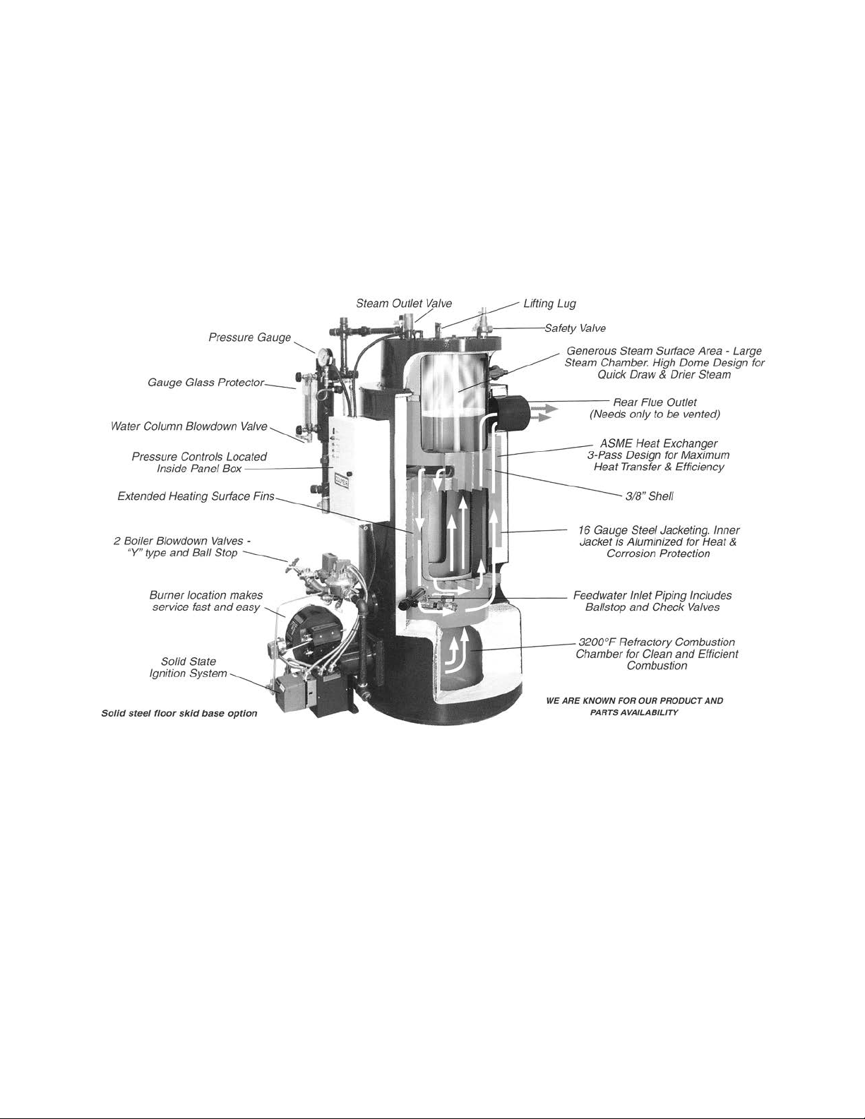
CT BOILER WITH PARTIAL SECTION
Figure 1

Table Of Contents
PARTS WARRANTY . . . . . . . . . . . . . . . . . . . . . . . . . . . . . . . . . . . . . . . . . . . . . . . . . . . 2
SERVICE POLICY . . . . . . . . . . . . . . . . . . . . . . . . . . . . . . . . . . . . . . . . . . . . . . . . . . . . . 3
INSTALLATION . . . . . . . . . . . . . . . . . . . . . . . . . . . . . . . . . . . . . . . . . . . . . . . . . . . . . . 4
CLEANING AND FILLING A NEW STEAM BOILER . . . . . . . . . . . . . . . . . . . . . . . . . 11
OPERATING THE BOILER . . . . . . . . . . . . . . . . . . . . . . . . . . . . . . . . . . . . . . . . . . . . . . 12
STARTING THE BOILER . . . . . . . . . . . . . . . . . . . . . . . . . . . . . . . . . . . . . . . . . . . . . 13
STOPPING THE BOILER . . . . . . . . . . . . . . . . . . . . . . . . . . . . . . . . . . . . . . . . . . . . . 13
BURNER START UP AND TEST INFORMATION . . . . . . . . . . . . . . . . . . . . . . . . . . . . 15
SIDEWALL VENTING . . . . . . . . . . . . . . . . . . . . . . . . . . . . . . . . . . . . . . . . . . . . . . . 16
BOILER ROOM . . . . . . . . . . . . . . . . . . . . . . . . . . . . . . . . . . . . . . . . . . . . . . . . . . . 19
DESCRIPTION OF BOILER COMPONENTS . . . . . . . . . . . . . . . . . . . . . . . . . . . . . . . 21
MAINTENANCE . . . . . . . . . . . . . . . . . . . . . . . . . . . . . . . . . . . . . . . . . . . . . . . . . . . . 25
MAINTENANCE LOGS . . . . . . . . . . . . . . . . . . . . . . . . . . . . . . . . . . . . . . . . . . . . . 31
TESTING OF BOILER COMPONENTS . . . . . . . . . . . . . . . . . . . . . . . . . . . . . . . . . . . 33
WATER TREATMENT . . . . . . . . . . . . . . . . . . . . . . . . . . . . . . . . . . . . . . . . . . . . . . . 39
RETURN SYSTEMS . . . . . . . . . . . . . . . . . . . . . . . . . . . . . . . . . . . . . . . . . . . . . . . . . . . 42
BLOWDOWN SEPARATOR . . . . . . . . . . . . . . . . . . . . . . . . . . . . . . . . . . . . . . . . . . . . . 43
TROUBLESHOOTING . . . . . . . . . . . . . . . . . . . . . . . . . . . . . . . . . . . . . . . . . . . . . . . . . 44
APPENDICES . . . . . . . . . . . . . . . . . . . . . . . . . . . . . . . . . . . . . . . . . . . . . . . . . . . . . . . 45
Replacement Parts for CT Series Boilers
Panel Box - Inside View - Replacements Parts
Warrick Probe Assembly - Replacement Parts
Replacement Parts List for CT Series Boilers
Gas Train Piping Diagrams
Gas Train Components
Boiler Wiring Diagram
Safety Valve Piping, typical
Warrick Dual Function Controls
Warrick Series 3K Electrode Fittings
Warrick Probe Series 26 Controls
Tubular Gage Glasses - Use and Care
Danfoss Pressure Controls
Typical CT Boiler Piping Layout - Drawing PL-098

FM-148 COLUMBIA BOILER COMPANY, REV 6-06
- 1 -
IMPORTANT
1. Read and familiarize yourself with this installation, operation, and maintenance manual before installing, operating,
or ser vicing your boiler.
2. All cover plates, enclosures, and safety devices must be
installed at all times except while performing maintenance
and ser vice.
3. Only trained service technicians should do any work on
your boiler.
4. All state and local codes take precedence over any recommendations given in this manual.
5.
NOTE: The CT Boiler is not designed for continuous, nonstop
operation. Normal burner cycling is required. Continuous operation will eventually damage the boiler, voiding the warranty.
6. Wrapping the CT Boiler with insulation will cause the boiler to
overheat, voiding the warranty.

FM-148 COLUMBIA BOILER COMPANY, REV 6-06
- 2 -
LIMITED PARTS WARRANTY
The Columbia Boiler company (hereinafter Columbia) warrants the burner components and controls installed on its boiler/burner units to be free from defects in material and workmanship under
normal use and service for 12 months from the date of installation or 18 months from the date of
manufacture, whichever date occurs first, and is subject to warranty approval by the manufacturer of the specific components. This warranty does not extend to equipment subjected to misuse,
neglect, accident or improper installation. Equipment which is defective in material or workmanship and is removed within 12 months from the date of installation will be repaired or replaced as
follows:
a. Motors, fuel units, controls, and transformers should be sent for repair or replacement to an
authorized service point or distributor of the manufacturer of such component when reasonably available in Customer’s locality.
b. Where such local service is not available with respect to the above listed components, or
where other components are involved, such defective equipment should be returned after
receiving authorization from your dealer, freight prepaid, to the Columbia Boiler Co., 390
Old Reading Pike, Pottstown, PA 19464. The use of Columbia returned goods form is
mandatory when returning defective material.
c. Columbia is not responsible for any labor cost for the removal and replacement of equip-
ment.
d. Equipment which is repaired or replaced will carry a warranty equal to the unexpired por-
tion of the original equipment warranty.
e. If inspection by Columbia does not disclose any defect covered by this warranty, the equip-
ment will be repaired or replaced at the expense of the Customer, and columbia’s regular
charges will apply.
THIS WARRANTY IS LIMITED TO THE PRECISE TERMS SET FORTH ABOVE, AND PROVIDES EXCLUSIVE REMEDIES EXPRESSLY IN LIEU OF ALL OTHER REMEDIES. ALL IMPLIED WARRANTIES, INCLUDING BUT NOT LIMITED TO ANY IMPLIED WARRANTY OF MERCHANTABILITY OR FITNESS FOR A
PARTICULAR PURPOSE OR USE, ARE EXCLUDED. IN NO EVENT WILL COLUMBIA BOILER CO. BE
LIABLE FOR ANY INCIDENT AL OR CONSEQUENTIAL DAMAGES OF ANY NATURE. Columbia neither
assumes nor authorizes any person to assume for columbia any other liability or obligation in connection with the sale of this equipment. Columbia’s liability and Customer’s exclusive remedy being
limited to repairs or replacement as set forth above.

FM-148 COLUMBIA BOILER COMPANY, REV 6-06
- 3 -
SERVICE POLICY
Anything mechanical will inevitably need servicing. Steam and hot water boilers are routinely serviced by the installer or another boiler maintenance company. Occasionally the
service technician may be unable to determine the cause of the problem. In this situation,
the dealer or service organization should contact the selling distributor for help.
Should the problem persist, the distributor will contact the sales representative for assistance. Depending on the extent of the problem, the representative may request technical
assistance from the factory.
If the problem cannot be resolved by the representative, he should contact the Technical
Service/Engineering Depar tment at the factory. The sales representative will need the following information. We must insist that this information be available to assure prompt service.
Boiler Model and Size (HP) ______________________________________________________
Boiler Serial Number ___________________________________________________________
Boiler National Board Number __________________________________________________
Date Installed _________________________________________________________________
Burner Type and Model ________________________________________________________
Installer’s Name ____________________________________Phone (_____) ______________
Address ______________________________________________________________________
Distributor’s Name __________________________________Phone (_____) ______________
Address ______________________________________________________________________
Sales Representative ________________________________ Phone (_____) ______________
Address ______________________________________________________________________
Specific Problem - Detailed

FM-148 COLUMBIA BOILER COMPANY, REV 6-06
- 4 -
INSTALLATION
The Columbia Model CT Steam Boiler is furnished completely piped, wired, and assembled. It has been factory tested and is ready for operation. This steam boiler is designed
to operate using No. 2 fuel oil and/or natural, manufactured, or liquid propane (LP) gas,
and to be powered by standard AC electrical service.
BEFORE BEGINNING INSTALLATION, CAREFULLY STUDY THESE INSTRUCTIONS AND ALL
CHARTS, DRAWINGS, AND DIAGRAMS SHIPPED WITH THE BOILER.
Installation must follow all state and local code requirements. The electrical installation must
be in accordance with the National Electrical Code.
CLEARANCES
The boiler is to be placed on noncombustible flooring, in an approved boiler room, with
the following clearances to combustible materials.
Underwriters Laboratories (UL) approved clearances:
Side: 18 inches
Top: 18 inches
Front: 48 inches
Chimney connector: 18 inches
Reduced clearance installation must follow the recommendations as outlined in NFPA-31.
Reduced clearance installations should be avoided if possible, as this will make it much
harder for qualified technicians to perform routine maintenance in and around your
boiler.
Clearances to noncombustible materials shall be in accordance with state and local codes.
In the absence of local codes, it is recommended that the above stated clearances be followed.
FLUE
The CT series boilers are pressure fired steam boilers, and need only to be properly vented. Consult the factory for proper venting of the boiler for any unusual conditions that may
exist at the job-site.
For boilers vented into a chimney, be cer tain the chimney is clean, and clear of obstructions. Connect the boiler flue outlet to the chimney using galvanized flue pipe. Refer to the
following list for proper size of the flue pipe. DO NOT REDUCE THE FLUE OR CHIMNEY SIZE
TO LESS THAN THE OUTLET SIZE ON THE BOILER. Consult the factor y if the boiler must be
vented into a chimney that is smaller than the boiler outlet size. The flue pipe should be
pitched upward at least 1/4" per foot of run. Use only elbows and straight sections. Tees
FM-148 COLUMBIA BOILER COMPANY, REV 6-06
- 5 -
may be used in straight sections with a barometric draft regulator. Tees, however, should
not be used for a ninety-degree turn. Each joint should be securely fastened with sheet
metal screws. The flue pipe must not be inserted beyond the inside wall of the chimney.
Columbia Boiler approves the use of galvanized “B” type vent that is suitable for 550°F
stack temperature as proper and safe for this application, but any and all codes take precedence.
PROPER FLUE
PIPE SIZE
CT-6 6"
CT-10 6"
CT-15 8"
CT-20 8"
CT-25 10"
CT-35 12"
CT-50 12"
GAS SUPPLY PIPING
Contact your local gas company to ensure that adequate gas service is available, and to
review applicable installation codes for your area.
The minimum gas supply pressure required by the burner is five inches water column for
the CT-6 and CT-10, and seven inches water column for the CT-15, CT-20, CT-25, CT-35
and CT-50. The maximum gas supply pressure to the burner is fourteen inches water column. Gas pressure greater than fourteen inches water column will require an additional
gas regulator to prevent damage to the primary gas regulator. Gas pressure below the minimum will cause combustion efficiency problems and should be avoided if possible. Low
gas pressure may also prevent the boiler from obtaining the desired input rate, which will
cause the boiler to be unable to produce the desired output. Consult the factory if your gas
supply pressure is not in the recommended range.
Use the following tables to determine the size of the main gas line required for the boiler
that is being installed. First determine the required input volume of gas needed at the gas
manifold, then determine the correct pipe size for the length of run needed.
BOILER

CAPACITY OF PIPE - CUBIC FEET OF GAS PER HOUR
AT 0.2" W.C. PRESSURE DROP
Equivalent
1" 1-1/4" 1-1/2" 2" 2-1/2" 3" 4"
Length (ft)
10 425 725 1170 2360 4300 6250 12800
20 300 520 800 1700 3000 4500 9300
30 250 425 690 1400 2500 3750 7500
40 210 360 560 1200 2100 3200 6400
50 190 325 500 1100 1900 2850 5800
60 180 300 480 1000 1800 2300 4800
80 150 260 410 850 1550 2000 4200
100 135 230 370 750 1375 1680 3500
150 110 190 300 600 1100 1200 2750
200 75 165 260 540 950 1000 2000
Fitting Equivalent Lengths of Standard Pipe in Feet for Listed Fittings
Std. Tee 5.5 7.5 9.0 12.0 13.5 15 20
Std. Elbow 2.7 3.7 4.5 5.5 6.1 8 11
FM-148 COLUMBIA BOILER COMPANY, REV 6-06
- 6 -
REQUIRED INPUT - CUBIC FEET OF GAS PER HOUR
GAS TYPE CT-6 CT-10 CT-15 CT-20 CT-25 CT-35 CT-50
NATURAL 252 399 630 840 1050 1470 2100
PROPANE 101 160 252 336 420 735 840
Vent lines, if required, are to be run outside the building, stopping clear of windows or
fresh air intakes. The vent should terminate in a way that will not allow the possibility of
water, dirt, insects, animals, and other matter from entering and clogging the vent pipe.
Gas lines should be tested for leaks using a soap solution. Your gas company may wish to
witness this test. Do not exceed the maximum pressures allowed by the valve train.
Additional gas piping information is included in the burner section of this manual.

FM-148 COLUMBIA BOILER COMPANY, REV 6-06
- 7 -
OIL SUPPLY PIPING
Consult the burner section of this manual for oil line type and sizing requirements for proper operation. The size of oil lines is extremely important for proper operation. Suction vacuums must be held to acceptable limits.
All oil feed lines must be air tight. Use as few fittings as possible when assembling the oil
lines. The slightest air leak, usually caused by loose fittings or bad gaskets, can cause poor
starts, smoky starts, sooting of burner par ts, inefficient operation, and a dangerous combustion condition.
A vacuum test should be done on all installation to ensure that all fittings are tight and the
oil lines are of proper size. Always use flare fittings instead of compression fittings on oil
service lines. Compression fittings allow more of a chance for air to be introduced into the
oil supply.
WARNING: TEFLON
® TAPE SHOULD NEVER BE USED WITH ANY OIL LINE CONNEC-
TIONS. THE USE OF TEFLON
® TAPE ON BURNER COMPONENTS OR OIL
SERVICE LINES WILL VOID MOST BURNER WARRANTIES.
For additional information consult the burner section of this manual.
ELECTRICAL SUPPLY
Connect the electric supply to the boiler and condensate return system as shown in the
wiring diagrams. Separate electrical services and disconnects must be provided for both
the boiler and the return system. If both 110 volts AC and 220 volts AC are needed, separate disconnects should be provided. The wiring must be installed in accordance with the
National Electrical Code and any other state and local codes.
All disconnects should provide overload protection to prevent injury to personnel or damage to equipment.
Be sure that the incoming voltages match that of the appliances before applying power.
Make a special point of checking the internal wiring of the blower motor as most motors
can be wired for either 110 or 220 volts.
FEEDWATER
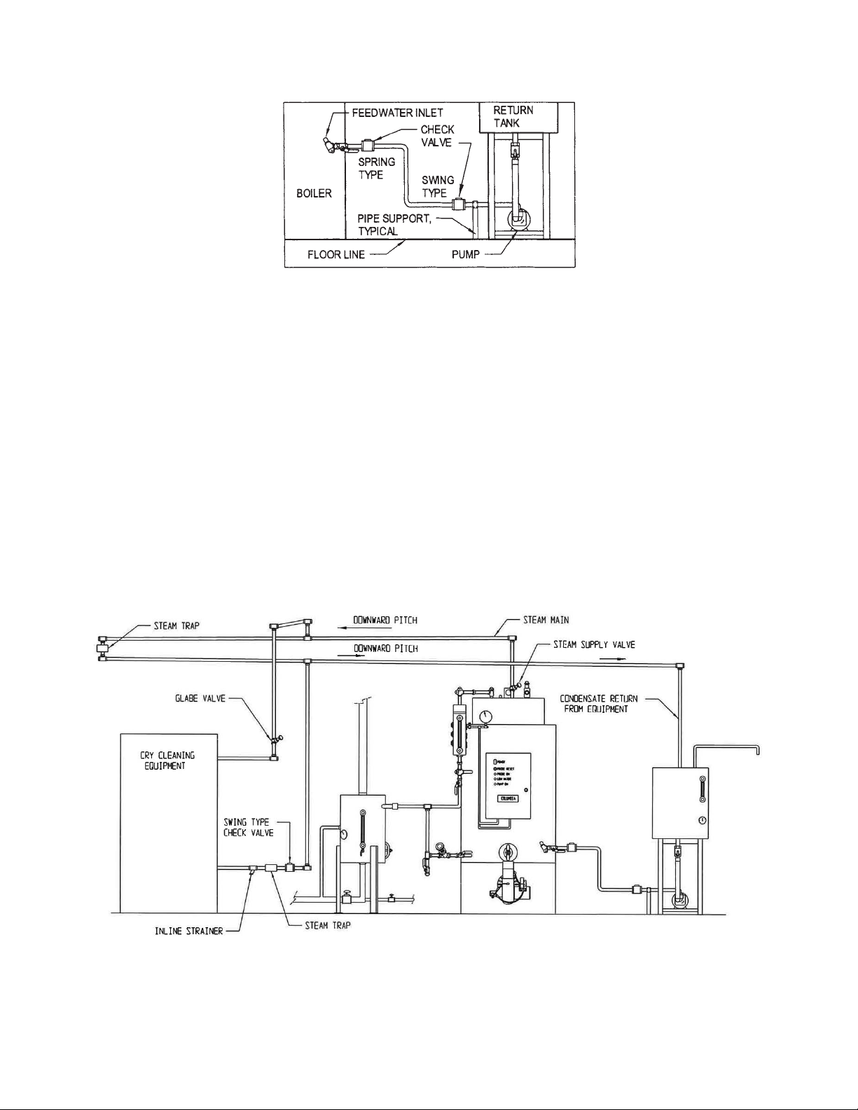
Connect the feedwater supply from the condensate return tank to the boiler inlet feedwater connection. See Figure 2 and Piping Layout PL-098 in Appendix. Columbia Boiler
Company provides one spring type check valve in the feedwater piping. An additional
swing type check valve should be installed in the feed line as close to the pump as possible. These valves should be piped in the horizontal position.
Do not use the pump as a piping support. It is very important that the piping be independently supported at the pump.
FM-148 COLUMBIA BOILER COMPANY, REV 6-06
- 8 -
FEEDWATER PIPING
Figure 2
Do not fill the boiler until the installation is complete and you are ready to fire the burner.
Firing the burner will then boil the water which will drive off the dissolved oxygen in the
water and help maintain the proper boiler water chemical balance.
See the WATER TREATMENT section for impor tant information regarding the proper chemical water treatment required to insure satisfactory ser vice life of the boiler.
On long horizontal runs of piping, it is best to maintain the piping as level as possible.
Avoid high spots that will collect air and lead to erratic pumping. Install a check valve to
prevent the boiler water from back feeding into the service water supply.
STEAM PIPING
Figure 3

FM-148 COLUMBIA BOILER COMPANY, REV 6-06
- 9 -
STEAM OUTLET
Connect the field steam piping to the outlet on top of boiler. See Figure 3. If a main steam
manifold is used, it should be pitched 1/4" per foot of horizontal run so that condensate
will run into a steam trap, rather than back into the boiler. All steam supplies should be
taken off the top of the manifold to prevent condensate from entering the process machines.
SAFETY VALVE
Safety valves should be piped so that they cannot discharge on people or damage property. The discharge piping must be supported so that the weight of the piping is not transmitted to the safety valve body. Refer to drawing PL-049 in the Appendix for an example
of typical safety valve piping. the weight supported by the valve outlet should not exceed
the weight of a drip pan elbow . Use only Schedule 40 pipe for discharge piping. DO NOT
USE Schedule 80, extra strong, or double extra strong discharge pipe or connections.
Installations requiring long discharge piping should not be connected directly to the safety valve.
During installation, be sure that pipe compound or tape is used only on external threads
and that the inlet of the valve is free of any foreign material.
DO NOT USE A PIPE WRENCH when working on the safety valve. use only the proper type
and size wrench.
WARNING: NEVER REDUCE THE INLET OR OUTLET SIZE OF THE SAFETY VALVE;
NEVER HANG PIPING ON THE SAFETY VALVE;
NEVER INSTALL VALVES(S) IN THE SAFETY VALVE PIPING;
NEVER PLUG THE BONNET VENT. SERIOUS DAMAGE OR INJURY
COULD RESULT FROM THE FAILURE OF THE SAFETY VALVE.
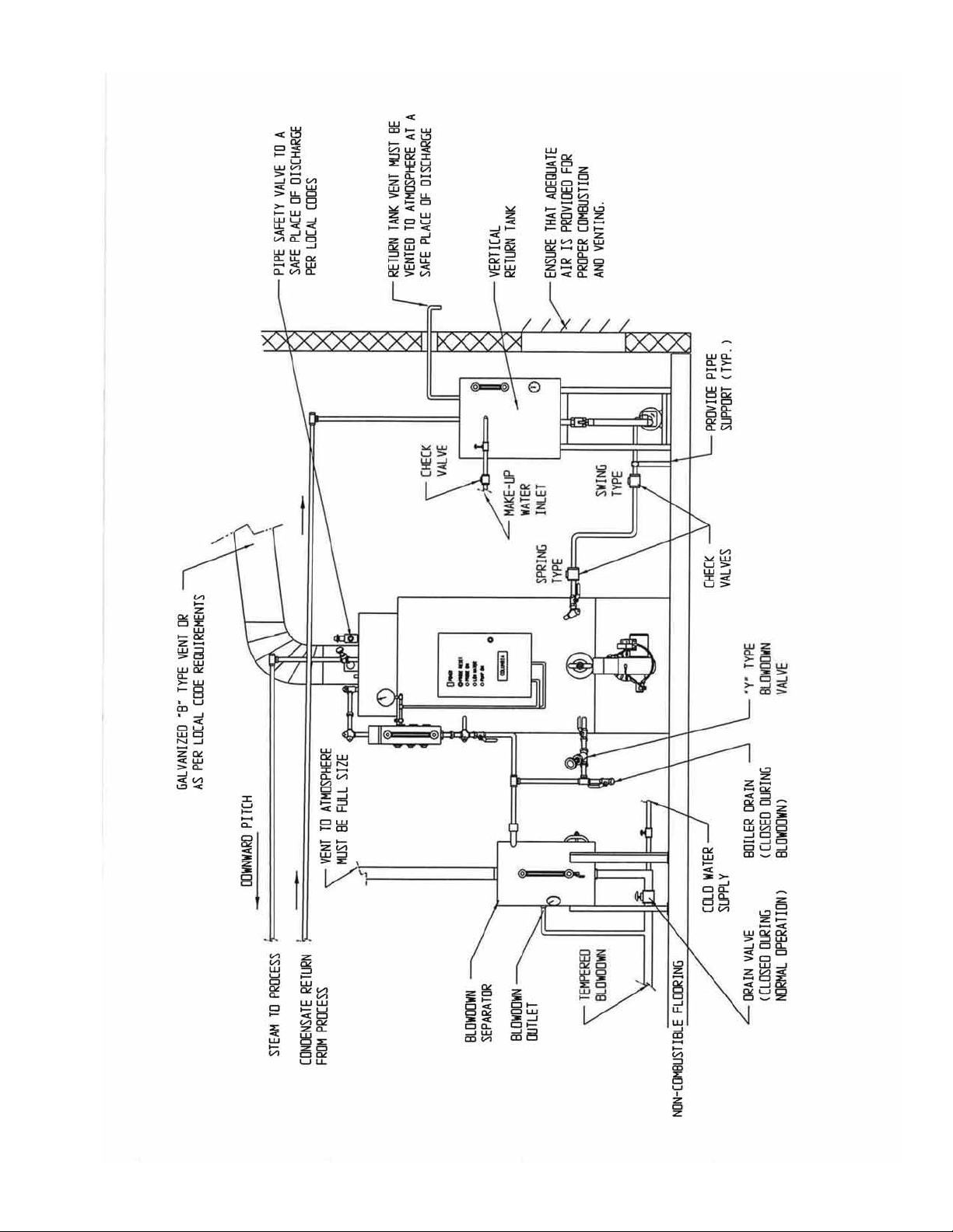
BLOWDOWN PIPING
Connect the boiler, the Warrick Low Water cut Off, and sight glass blowdown lines in
accordance with local code requirements. See Figure 4. the blowdown must be piped to
a safe place of discharge to prevent injury to personnel or proper ty damage.
It is recommended that a blowdown tank be used to safely discharge the blowdown into
the sewers. Check state and local codes concerning the maximum allowable temperature
for blowdown entering public sewer systems.
All valves, piping, and forged fittings used n the blow-down lines shall be, of suitable rating, and in accordance with ASME Code B31-Power Piping. All pipe nipples used shall
be Schedule 80 pipe.
WARNING: NEVER REDUCE THE VENT SIZE OF THE BLOWDOWN TANK.
To properly and safely blow down the boiler, the vent must be piped full size for the entire
length, and must terminate at a safe place of discharge per local codes.
FM-148 COLUMBIA BOILER COMPANY, REV 6-06
- 10 -
Figure 4
BLOWDOWN PIPING
FM-148 COLUMBIA BOILER COMPANY, REV 6-06
- 11 -
CLEANING AND FILLING A NEW STEAM BOILER
In order to minimize the corrosive effects of raw water oxidation on the boiler, the water
must be heated to at least 180°F immediately after entering the boiler , in order to drive off
the corrosive dissolved gases. This applies to all water - whether from a well, a spring, or
from the local municipal water system.
The oil and grease that accumulate in a new steam boiler can usually be washed out by
boiling as follows:
1. Fill the boiler to the normal waterline.
2. Provide a boil-out compound of caustic soda and trisodium phosphate in the pro-
portions of 2-1/2 lbs. of each chemical per 120 gallons of water.
CAUTION: USE CARE IN HANDLING THESE CHEMICALS. THE CAUSTIC
SODA IS EXTREMELY CORROSIVE TO SKIN AND CLOTHING. DO
NOT PERMIT EITHER THE DRY MATERIAL OR THE CONCENTRATEED SOLUTION TO CONTACT SKIN OR CLOTHING.
3. Mix the chemicals with water and pour into the boiler through any convenient
opening in the boiler.
4. Start the firing equipment.
5. Boil the water for at least five hours.
6. Stop the firing equipment.
7. Drain the boiler to a location where hot water can be discharged safely.
8. Wash the boiler thoroughly using a hose with sufficient pressure.
9. Fill the boiler to the normal waterline.
10. Add boiler water treatment as prescribed by a water treatment specialist.
11. Boil or bring water temperature to at least 180°F immediately.
12. The boiler is ready to put into ser vice or on standby.
EQUAL AMOUNTS
CAUSTIC SODA AND
TRISODIUM PHOSPHATE
CT-6 5 1/3 oz.
CT-10 8 oz.
CT-15 12 oz.
CT-20 1 lb.
CT-25 1 lb. 4 oz.
CT-35 1 lb. 14 oz.
CT-50 4 lbs. 9 oz.
BOILER
MODEL

FM-148 COLUMBIA BOILER COMPANY, REV 6-06
- 12 -
OPERATING THE BOILER
NOTE: Although your new Columbia Boiler has been test fired at the factor y, it must be
“set up” for the conditions at your location. Improper combustion settings may
cause the burner to operate erratically, resulting in boiler shutdowns, lost time,
and unnecessar y service expenses.
PRE-START CHECKS AND INFORMATION
A new or relocated boiler should not be put into service until it has been inspected by an
authorized inspector for the jurisdiction or the insurance company, and the required certificates have been issued.
Whenever a new boiler is placed in service, operating data should be recorded and saved
for future reference. This information is extremely valuable for diagnosing problems if
abnormal operation occurs. Record all operating parameters such as pressures, stack temperatures, oxygen or carbon dioxide levels, flows, draft, motor amps, damper positions,
and interlock set points. A burner start up and test information sheet has been included at
the end of this section for your convenience.
The Gauge Glass Protector must be properly installed prior to operating the boiler, and all
cover plates, enclosures, and safety devices must be installed at all times except while performing maintenance and service.
The fuel supply should not be turned on until the combustion chamber has been vented and
the pilot light (if gas ignited) checked for proper operation.
All blowdown valves, including water column drain valves, gauge glass drain valves, and
gauge cocks should be closed.
The safety valves should be inspected externally to see that they are free to operate, and
that the discharge piping and drain piping are open to the atmosphere, and free to
expand without imposing a load on the safety valve bodies. Make sure the safety valve is
piped to a safe location to prevent injury.
The boiler feed pump(s) should be checked to ensure that they are ready for service. Check
the data on rating plates of all electrical equipment to be certain the electrical characteristics match those of the electric supply to which they are connected.
All Columbia boiler company CT Series boilers are test fired at the factory, however , before
attempting start-up, carefully study the instructions included in the burner section of this
manual.
It is important to have the proper test equipment in order to adjust the combustion and pilot
if equipped. Those items that may be required include a manometer, microammeter, vacu-

FM-148 COLUMBIA BOILER COMPANY, REV 6-06
- 13 -
um gauge, 0-300 PSI pressure gauge, carbon dioxide or oxygen analyzer , carbon monoxide tester, smoke gun, and stack thermometer.
STARTING THE BOILER
WARNING: NEVER OPERATE A BOILER WITHOUT BEING SURE IT IS FILLED WITH WATER
AND THAT PROPER WATER TREATMENT CHEMICALS HAVE BEEN ADDED.
Open the feedwater valve and turn on the main disconnect for the condensate pump. the
pump should come on and fill the boiler to its normal operating level.
Turn the boiler disconnect switch to the ON position.
NOTE: The burner will not operate when the boiler has reached its normal water level,
until the reset button on the secondary, probe type, low water cut-off is pushed.
Push the RESET button on the Control panel Cover. The burner should start.
NOTE: Combustion efficiency must be checked at this time. See the burner manufacturers
instructions for correct settings and more detailed information.
Follow the adjustment procedures outlines in the burner section of this manual to set up the
burner for proper operation.
NOTE: New CT boilers will normally expel a vapor from joints and openings in the
jacket. This is a temporar y condition, caused by moisture evaporating out of the
refractor y insulation behind the jacket, and will eventually disappear.
STOPPING THE BOILER
To stop the boiler turn the main disconnect to the OFF position.
FM-148 COLUMBIA BOILER COMPANY, REV 6-06
- 14 -
GAS BURNERS
BOILER
BURNER
MODEL
POWER FLAME
CT-6 5/16 (.313) / 3.5" “D”(.242) / 3.5"
JR15A-10
POWER FLAME
CT-10 3/8 (.375) / 3.5" 19/64 (.297) / 3.5"
JR15A-10
POWER FLAME
CT-15 15/32 (.469) / 3.5" “T”(.358) / 3.5"
JR15A-10
POWER FLAME
CT-20 9/16 (.563) / 3.5" 15/32 (.469) / 3.5"
JR30A-12
POWER FLAME
CT-25 23/32 (.719) / 3.5" 1/2 (.500) / 3.5"
JR30A-12
POWER FLAME
CT-35 11/16 (.688) / 3.5" 19/32 (.594) / 3.5"
JR50A-15
POWER FLAME
CT-50 None x 3.5" 25/32 x 3.5"
JR50A-15
INLET GAS PRESSURE
Inlet gas pressure to the main gas valve should be between seven and fourteen inches
water column.
If the inlet gas pressure exceeds fourteen inches water column, the pilot regulator and main
gas regulator will “lock up” and become inoperative, and damage may occur. Inlet gas
pressure above fourteen inches water column will require an additional pressure reducing
valve.
If the inlet gas pressure is below seven inches water column the burner may not be capable of the rated boiler output. If the gas pressure is below seven inches water column contact your local gas company. If the local gas company is unable to help, contact the factory for assistance.
NATURAL GAS
ORIFICE SIZE AND
ORIFICE PRESSURE
(INCHES WATER OCLUMN)
LIQUID PROPANE GAS
ORIFICE SIZE AND
ORIFICE PRESSURE
(INCHES WATER COLUMN)

FM-148 COLUMBIA BOILER COMPANY, REV 6-06
- 15 -
BURNER START UP AND TEST INFORMATION
For a new boiler start up, or for troubleshooting an existing installation, the following information is essential for effective service assistance.
Boiler Model__________________ Serial No.______________ N.B. No._______________
Burner Model_________________ Invoice No._____________ Serial No.______________
Installation Name______________________________________ Start Up Date____________
Start Up Contractor____________________________________ Phone No.______________
Name of Technician Performing Star t Up__________________________________________
Fuel T ype: q Natural Gas q LP Gas q Fuel Oil (#2) q Other_____________________
Gas Firing
Gas Pressure At Train Inlet
Burner in Off Position________"W.C.
Gas Pressure At Train Inlet
High Fire__________________"W.C.
Gas Pressure At Main Orifice
High Fire__________________"W.C.
Gas Pressure At Pilot Orifice
__________________________"W.C.
Oil Firing
High Fire Vacuum Reading At Oil
Pump Inlet__________________"H.G.
Oil Nozzle Supply Pressure
Low Fire______________________PSI
High Fire_____________________PSI
Firing Rate - GPH
Low Fire________________________
High Fire_______________________
Operational Check of Controls
Operating Limit_________________q
Safety Limit____________________q
Low Water Cut Off______________q
Flame Signal Readings
Pilot____________________________
CO2
High Fire________________________
CO
High Fire________________________
Measured INput Rate - BTU/HR
High Fire __________________"W .C.
CO2
Low Fire ________________________
High Fire________________________
Bachrach Scale Smoke Number
Low Fire ________________________
High Fire________________________
Over Fire Draft
Low Fire___________________"W.C.
High Fire __________________"W .C.
Aux LWCO ____________________q
Low Gas Pressure ______________q
High Gas Pressure ______________q
Stack Outlet Test Point Draft
High Fire __________________"W .C.
Over Fire Draft
High Fire __________________"W .C.
Net Stack Temperature
High Fire______________________°F
Gas Pressure At Pilot Orifice
__________________________"W.C.
Stack Outlet Test Point Draft
Low Fire___________________"W.C.
High Fire__________________"W.C.
New Stack Temperature
Low Fire______________________°F
High Fire_____________________°F
Flame Safeguard _______________q
Ignition Failure q
Flame Failure q
Comments
________________________________________________________________________________________________________
________________________________________________________________________________________________________
________________________________________________________________________________________________________
________________________________________________________________________________________________________
________________________________________________________________________________________________________
________________________________________________________________________________________________________
________________________________________________________________________________________________________
FM-148 COLUMBIA BOILER COMPANY, REV 6-06
- 16 -
OPTIONAL SIDEWALL VENTING (and Combustion Air intake)
Installation Instructions
General
This section provides instructions for the installation of UL listed Gas-Fired Boiler Assemblies
with Side Wall Venting and Combustion Air intake Assemblies, MEA number 15-95-E.
While the instructions and suggestions set forth in this manual are safe and proper, it is the
responsibility of the installer and the owner to assure adherence to all local codes.
Equipment (Available with Power Flame Burners Only)
Note: All Columbia boilers ordered for Sidewall Venting will be provided with a
Combustion Air Intake Adapter.
CT-6 Boiler with Power Flame JR15A-10 Burner
CT-10 Boiler with Power Flame JR15A-10 Burner
CT-15 Boiler with Power Flame JR15A-10 Burner
CT-20 Boiler with Power Flame JR30A-10 Burner
CT-25 Boiler with Power Flame JR30A-12 Burner
CT-35 Boiler with Power Flame JR50A-15 Burner
VENT SIZE INTAKE SIZE
BOILER MODEL
DIAMETER (INCHES) DIAMETER (INCHES)
CT-6 6 6
CT-10 6 6
CT-15 8 6
CT-20 8 6
CT-25 10 6
CT-35 12 8
CT-50 NOT UL OR MEA APPROVED FOR THIS OPTION
Vent Caps
Use only UL listed vent caps for the combustion vent termination and the combustion air
intake. The following vent cap model is shipped with your boiler when the direct vent
option kit is ordered.
Heat-Fab Incorporated
38 Haywood Street
Greenfield, MA 01301
(800) 772-2356 “Saf-T CI Vent Rain Cap”
FM-148 COLUMBIA BOILER COMPANY, REV 6-06
- 17 -
Installation
The Columbia Model CT Direct Vent Series Steam Boiler is furnished completely piped,
wired, and assembled. It has been test fired at the factory and is ready for installation. This
steam boiler is designed to operate with natural gas, and is suitable for standard AC electrical service. The CT Series requires the following minimum clearances to combustible
material: top, sides, and rear - 18", front - 36", flue vent duct - 18".
Location
The CT boiler must be mounted on a level non-combustible floor, or the floor must be protected in accordance with the requirements of accepted building code practices. In the
absence of local codes, it is suggested that NFPA-31 section 4-4.1.5 be followed.
Flue Vent Duct
For direct venting, galvanized smoke pipe is acceptable, but local codes take precedence.
The maximum length of flue vent duct allowed is 40 feet, and at no time can the diameter
of the flue vent duct be less than the diameter of the smoke outlet of the boiler, see Table
on the previous page for size. The flue pipe should be sloped upward 1/4" per horizontal foot of run. All sections of flue pipe should be joined and fastened securely with sheet
metal screws. The maximum number of 90° elbows in the flue vent duct is four. A barometric swing type draft regulator may be installed in the flue vent duct if desired, but is not
necessary.
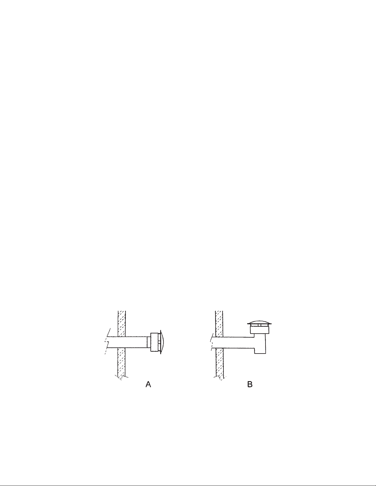
The vent must end with the UL listed vent cap that was shipped with your boiler. the vent
cap can be installed either horizontally (Figure 5-A below) or vertically with a tee (Figure
5-B below). It is suggested that a screen or vent pipe plug be inserted into the bottom of
the tee to prevent animals and other matter from entering.
Figure 5
FM-148 COLUMBIA BOILER COMPANY, REV 6-06
- 18 -
All through the wall connections must adhere to safety standards set forth by standard
building practices and local codes. In the absence of local codes, UL listed wall thimbles
and through the wall connectors should be used.
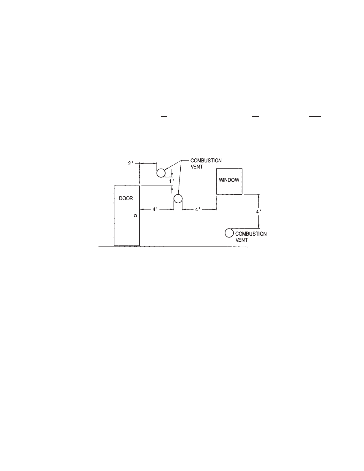
The combustion vent cap must extend a minimum of four feet from the building, and must
be located as far from the combustion air intake as possible. The combustion vent must terminate a minimum of seven feet above the ground where pedestrian traffic can be expected. It shall also terminate at least three feet above any forced air inlet within ten feet, and
shall terminate at least four feet below or
four feet horizontally from, or one foot above and
two feet horizontally from, any door, window, or gravity air inlet into any building as provided in the National Fuel Gas Code NFPA 54. See Figure 6. Both the Combustion Flue
Vent and the combustion Air Intake must be in the same wall.
COMBUSTION VENT LOCATIONS
Figure 6
Combustion Air Intake
The air for combustion must be ducted directly to the burner intake and must terminate outside with the applicable Intake Air cap listed in the Table on page 15. The vent cap can
be installed either horizontally or vertically in conjunction with a tee. It is suggested that a
screen or vent pipe plug be inserted into the bottom of the tee to prevent animals and other
matter from entering. The maximum length of combustion air intake duct shall be 40 feet.
The combustion air intake shall be full size for the complete run and shall not have more
than four 90° elbows. The combustion air intake cap must be at least one foot off the
ground in an area that is always free from obstructions. The Combustion Air Intake must
be in the same wall as the Combustion Vent.
Important Note: Surface discoloration of the building may occur due
to improper boiler/burner adjustment and maintenance. Columbia
Boiler Company will not accept any liability for such discoloration.

FM-148 COLUMBIA BOILER COMPANY, REV 6-06
- 19 -
BOILER ROOM
Lighting
The boiler room should be well lighted and should have a source of emergency lighting. If
a flashlight is used for this purpose, it should be maintained in usable condition, and it
should not be removed from the boiler room.
Care should be taken to prevent bright, direct sunlight from shining on the burner, as the
flame sensing controls may receive a false flame signal.
Water Supply and Drain Connections
Convenient water supply connections for flushing the boiler and cleaning the boiler room
floor should be installed.
Unobstructed floor drains, properly located in the boiler room floor, will aid in the proper
cleaning of the boiler room.
Make-up Air
The burner must have adequate air supply, which must be kept clear at all times. Do not
run exhaust fans in the immediate proximity of the boiler room, as they will cause a reversal of draft at the burner. Ensure that sufficient make-up air is available, even if that requires
a window to the outside to be left open. This air is necessary to insure complete combustion, a clean fire, and to prevent nuisance shutdowns due to excessively dirty burner parts.
Air from the outside may be provided through ducts, fixed louvers, or motorized louvers.
WARNING: WITHOUT SUFFICIENT MAKE-UP AIR, THE BOILER WILL NOT OPERATE
PROPERLY, AND BURNER COMPONENT DAMAGE COULD OCCUR.
To calculate the required fresh air opening to the outside, allow 21 square inches for every
boiler horsepower. For example a 10-horsepower boiler would require two hundred and
ten square inches of free opening. This is equal to a 15" x 15" square hole, or a 18" diameter round hole of free, unrestricted area. If louvers or screens are used, contact the manufacturer for percentages (typically around 40%) that must be added to allow for restriction.
The following table can be used to size the amount of free area needed for the various
sizes of CT boilers. A point to remember for round openings - two 10" round openings DO
NOT equal one 20" round opening. Four 10" round openings are needed to obtain the
same amount of free area.
Columbia Boiler Company will not be held liable for damage to the
boiler or burner components caused by insufficient burner make up
air.
 Loading...