

Columbia CSFE-3090S, CSFE-3090ST, CSFE-4125S, CSFE-4125ST, CSFE-5185S Installation, Operation & Maintenance Manual
...
MODELS
CSFE-3090S
CSFE-3090ST
CSFE-4125S
CSFE-4125ST
CSFE-5185S
CSFE-5185ST
CSFE-6210S
CSFE IV STEAM Series 4
OIL-FIRED
CAST IRON BOILER
INSTALLATION, OPERATION &
MAINTENANCE MANUAL
CSFE-6210ST
PATENT 7,823,544
Manufacturedby:
ECRInternational,Inc.
2201 Dwyer Avenue, Utica NY 13504-4729
web site: www.ecrinternational.com
P/N 240009803, Rev. A [10/2012]
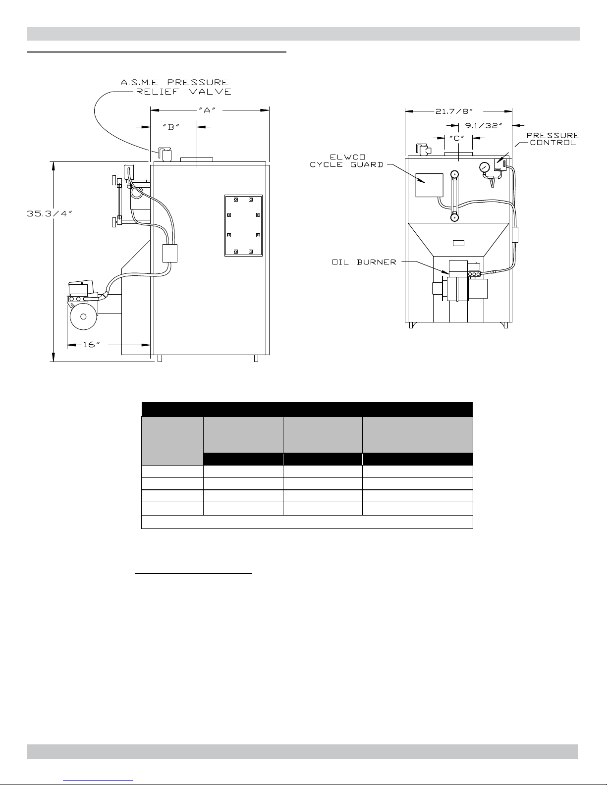
Figure #1
DIMENSIONS
DIMENSIONS
Front of Jacket
to Center Line of
Flue Outlet
Flue Outlet Diameter
Boiler No.
Length of Flush
Jacket
-A- -B- -C-
CSFE -3090 16⅜" 6½" 6"
CSFE -4125 20¼" 8½" 6"
CSFE -5185 23⅝"10¼"7"
CSFE -6210 27½" 85⁄16" 8"
* Boiler model number on rating plate includes suffi x 'S' or 'ST'.
STANDARD EQUIPMENT: Crated boiler, fl ush jacket, oil burner,
target wall/liner, safety valve, steam water level gauge, steam
pressure gauge, steam pressure control, low water cut-off, drain
valve, wiring harness, burner electric disconnect, plastic cover, 2"
supply tapping, 1½" return tapping, skim port, and primary control.
(NOTE: For tankless heater units, add tankless hot water coil, and
low limit control.)
2
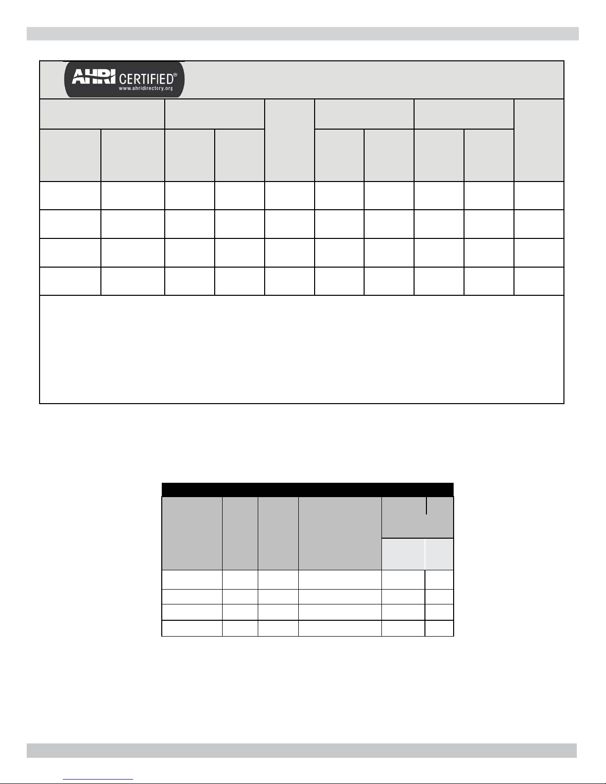
RATINGS, DATA
RATINGS
Boiler Model
Number
Oil Burner Input
(1)
Capacity
(4)
WITHOUT
TANKLESS
CSFE -3090 S CSFE -3090 ST
CSFE -4125 S CSFE -4125 ST
CSFE -5185 S CSFE -5185 ST
CSFE -6210 S CSFE-6210 ST
NOTES:
(1)
Burner input is based on an oil heating value of 140,000 Btu/gal.
(2)
MBH = 1000 Btu per hour [Btu = 15 Amps, 60 Hz
WITH
TANKLESS
G.P.H. MBH
0.90 126 106 80 333 6 8"x8"x15' 82.0
1.25 175 147 110 458 6 8"x8"x15' 82.0
1.85 259 216 162 675 8 8"x8"x15' 82.0
2.10 294 247 185 771 8 8"x8"x15' 82.0
(2)
MBH
Net AHRI Ratings
Steam
MBH
Sq. Ft.
Steam
Min. Natural Draft
(3)
Chimney Size
Round
A.F.U.E.
Rating
Square
Boiler Model
Number
CSFE-3090 ST
CSFE -4125 ST
CSFE -5185 ST
CSFE -6210 ST
TANKLESS WATER HEATER CAPACITIES
Boiler Water
Input
G.P.H.
Tankless
Rate
Heater
Number
0.90 L-24 2 11 8
1.25 L-24 4½ 13 9
1.85 L-24 4½ 15 10
2.10 L-24 4½ 17 11
Tankless
Heater Capacity
Intermittent Draw
G.P.M.
Content
(Gallons)
To Water
Line
LWCO
3
To
Line
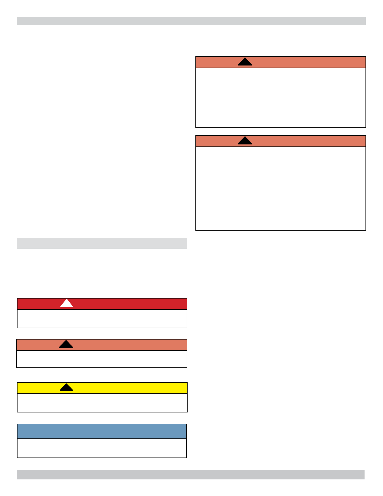
TABLE OF CONTENTS
!
Dimensions ........................................................2
Ratings, Data .....................................................3
Safety Symbols ..................................................4
Locating The Boiler .............................................5
Ventilation And Combustion Air ............................6
Supply And Return Piping ....................................8
Venting System Inspection & Installation .............12
Oil Tank And Piping ........................................... 13
Electrical Wiring ............................................... 14
Operating Instructions .......................................16
Maintenance Procedures ....................................19
Service Checklist ..............................................21
KEEP THIS MANUAL NEAR BOILER
RETAIN FOR FUTURE REFERENCE
IMPORTANT: Read and understand the following
instructions COMPLETELY before installing.
!
WARNING
Installations of boilers and venting shall be done
only by qualifi ed expert and in accordance with this
manual. Installing or venting a boiler or any other
gas appliance with improper methods or materials
could result in serious injury or death due to fi re
or to asphyxiation from poisonous gases such as
carbon monoxide which is odorless and invisible.
!
WARNING
Keep boiler area clear and free from combustible
materials, gasoline and other fl ammable vapors and
liquids.
Do not obstruct air openings to boiler room.
Modifi cation, substitution or elimination of factory
equipped, supplied or specifi ed components could
result in personal injury or the loss of life.
SAFETY SYMBOLS
The following defi ned symbols are used throughout this
manual to notify reader of potential hazards of varying risk
levels.
!
DANGER
Indicates a hazardous situation which, if not
avoided, WILL result in death or serious injury.
!
WARNING
Indicates a hazardous situation which, if not avoided,
could result in death or serious injury.
!
CAUTION
Indicates a hazardous situation which, if not
avoided, could result in minor or moderate injury.
Owner - Installation and service of this boiler must
be performed by a qualifi ed installer.
Installer - Leave all instructions with the boiler for
future reference.
When this product is installed in the Commonwealth
of Massachusetts the installation must be performed
by a Licensed Plumber or Licensed Gas Fitter.
NOTICE
Indicates information which should be followed to
ensure proper installation and operation.
PATENT 7,823,544
4
LOCATING THE BOILER
• Installations shall conform to the requirements of
the authority having jurisdiction. Such applicable
requirements take precedence over the general
instructions of this manual.
• Where required by the authority having jurisdiction,
the installation must conform to the American Society
of Mechanical Engineers Safety Code for Controls and
Safety Devices for Automatically Fired Boilers, ANSI/
ASME No. CSD-1.
• Locate boiler in front of fi nal position before removing
crate.
• Provide level solid base as near chimney as possible
and centrally located with respect to heat distribution
system as practical.
• Allow 24 inches in front, top and right hand side for
servicing and cleaning, or removing tankless water
heating coil.
• Recommend 24 inches be allowed in back of boiler for
convenience when skimming hole is used.
• When installed in a utility room, the door should be
wide enough to allow largest boiler part to enter, or to
permit replacement of another appliance such as water
heater.
• Install boiler such that oil ignition system components
are protected from water (dripping, spraying, rain etc.)
during appliance operation and service.
FOR INSTALLATION ON NON-COMBUSTIBLE FLOORS ONLY
Boiler must not be installed on carpeting or vinyl fl ooring.
Minimum clearances to combustible construction are:
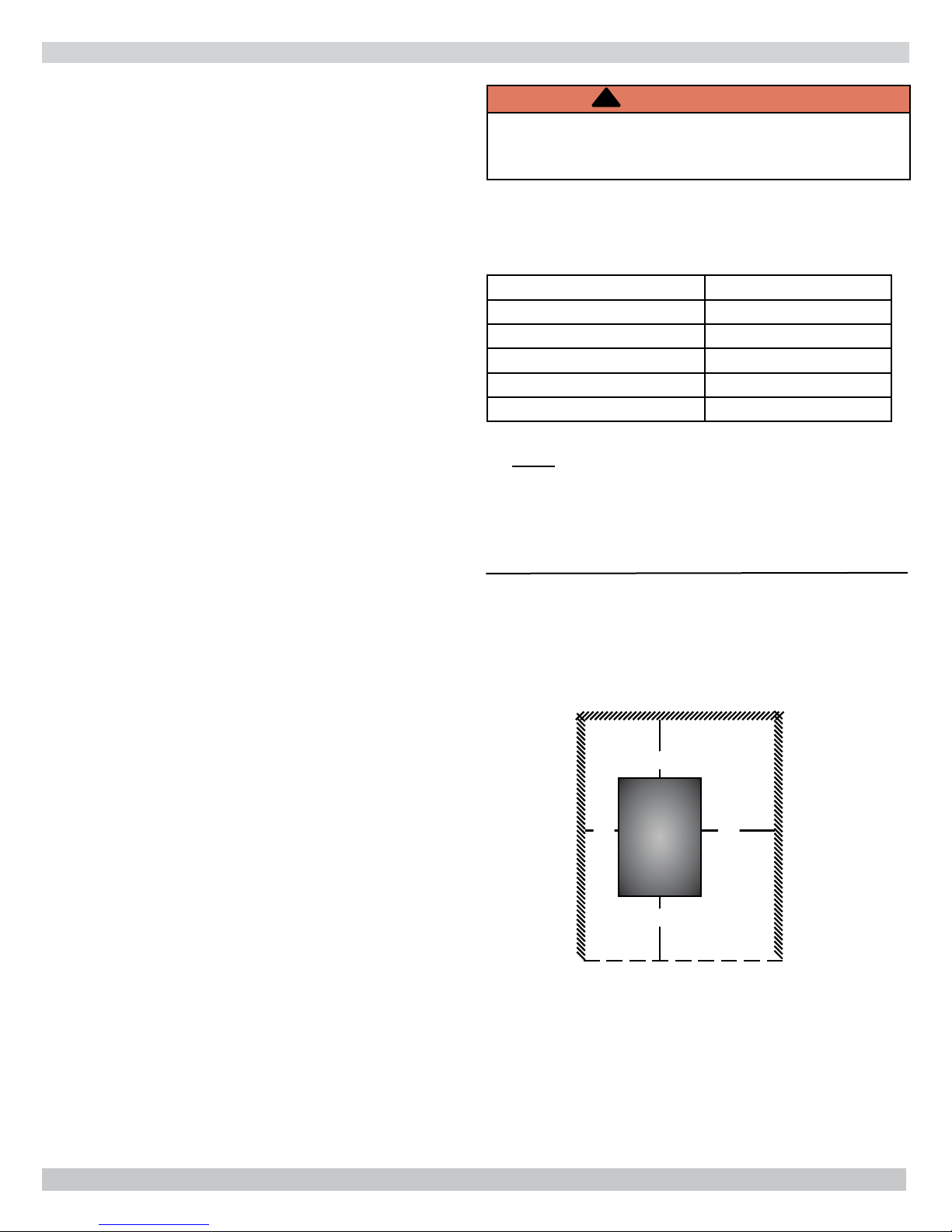
Figure #2 - Minimum Clearances To Combustible
Construction (as seen from above)
!
WARNING
Fire hazard. Do not install boiler on combustible
fl ooring or carpeting. Failure to follow these
instructions could result in death or serious injury.
TOP 24 IN.
FRONT 24 IN.
FLUE CONNECTOR 9 IN.
REAR 24 IN.
LEFT SIDE 6 IN.
RIGHT SIDE 24IN.
NOTE: Clearance for access should exceed fire protection
clearance.
BACK
24"
6" 24"
BOILER
24"
FRONT
5
VENTILATION AND COMBUSTION AIR
!
WARNING
Asphyxiation, fi re hazard. Do not obstruct air
openings to combustion area. Follow instructions
below, to maintain adequate combustion air.
COMBUSTION AIR REQUIREMENTS
(Minimum Opening Requirement)
Unconfi ned Area* Confi ned Area**
Outside Inside Outside Combustion Air
Input (Mbh)
Combustion Air
1 Sq.In./5000 BTU/Hr
(Step 4)
126 26 126 32 63
175 35 175 44 88
259 52 259 65 130
294 59 294 74 147
* A space whose volume is not less than 50 cubic feet per 1000 BTU/Hour of all appliances installed in that space (cubic feet of
space = height x width x length)
** A space whose volume is less than 50 cubic feet per 1000 BTU/Hour of all appliances installed in that space (cubic feet of space
= height x width x length)
Combustion Air
1 Sq. In./1000 BTU/
Hr (Min. 100 Sq. In.)
(Figure #1)
Vertical Ducts
1 Sq. In./4000 BTU/Hr
1 Sq. In./2000 BTU/Hr
(Figures # 2 & #3)
Horizontal Ducts
(Figure # 4)
1.
Ventilation of boiler room must be adequate enough to
provide suffi cient air to properly support combustion,
venting and maintain safe ambient temperatures under
normal operating conditions.
2.
When the boiler is located in an unconfi ned space in a
building of conventional construction frame, masonry
or metal, infi ltration normally is adequate to provide
air for combustion and ventilation. However, in any
building which has been altered to conserve energy
or to minimize infi ltration, the boiler area should
be considered as a confi ned space. If there is any
doubt, install air supply provisions for combustion
and ventilation in accordance with Chapter 5, Air for
Combustion and Ventilation, of NFPA 31, Standard
for the Installation of Oil Burning Equipment. The
recommendations that follow, or applicable provisions
of the local building codes.
3.
When the boiler is installed in an unconfi ned space,
in a building of unusually tight construction, air for
combustion and room ventilation must be obtained
from outdoors or from spaces freely communicating
with the outdoors. A permanent opening or openings
having a total free area of not less than 1 square inch
per 5,000 BTU per hour of total input rating of all
appliances shall be provided. Ducts may be used to
convey make-up air from the outdoors and shall have
the same cross-sectional area of the openings to which
they are connected.
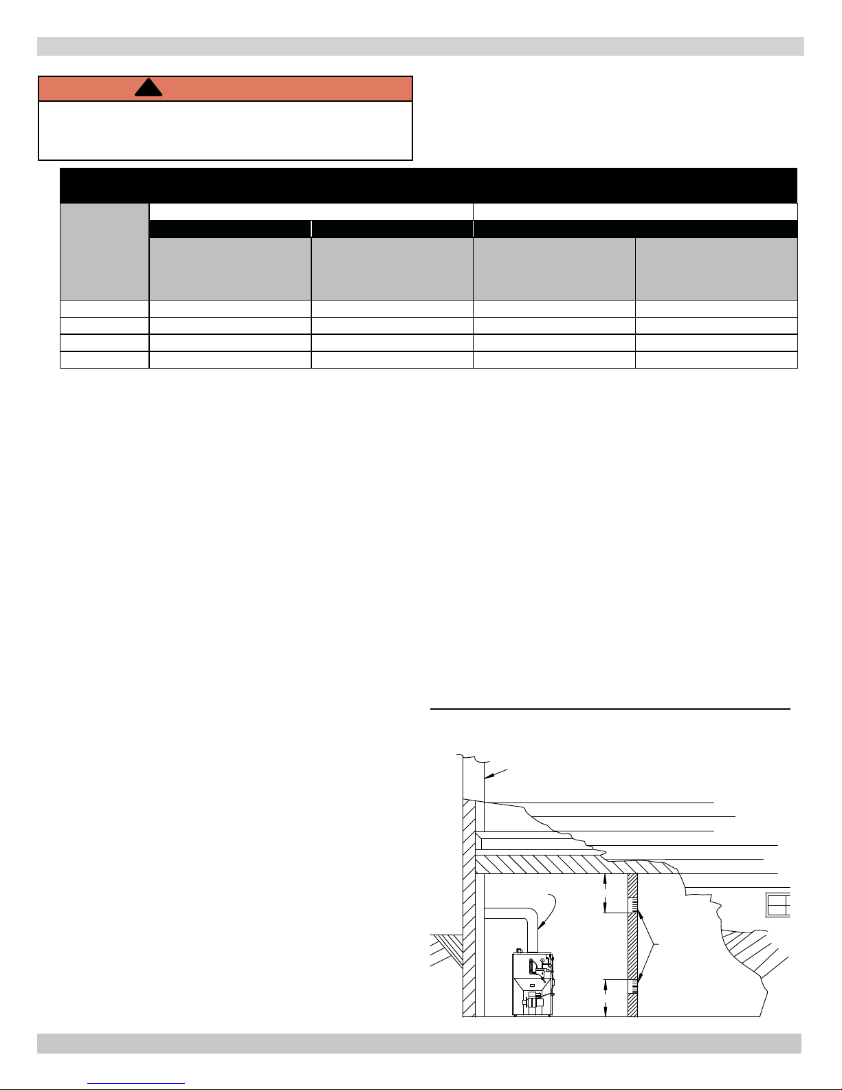
4.
When air for combustion and room ventilation is from
inside buildings, the confi ned space shall be provided
with two permanent openings, one starting 12 inches
from the top and one 12 inches from the bottom of the
enclosed space. Each opening shall have a minimum
free area of 1 square inch per 1,000 BTU per hour of
the total input rating of all appliances in the enclosed
space, but must not be less than 100 square inches.
These openings must freely communicate with the
interior areas having adequate infi ltration from the
outside. See Figure #3.
Figure #3
CHIMNEY
OR
L TYPE VENT PIPE
BASEBOARD
VENT PIPE
12"
VENTS
12"
6
VENTILATION AND COMBUSTION AIR
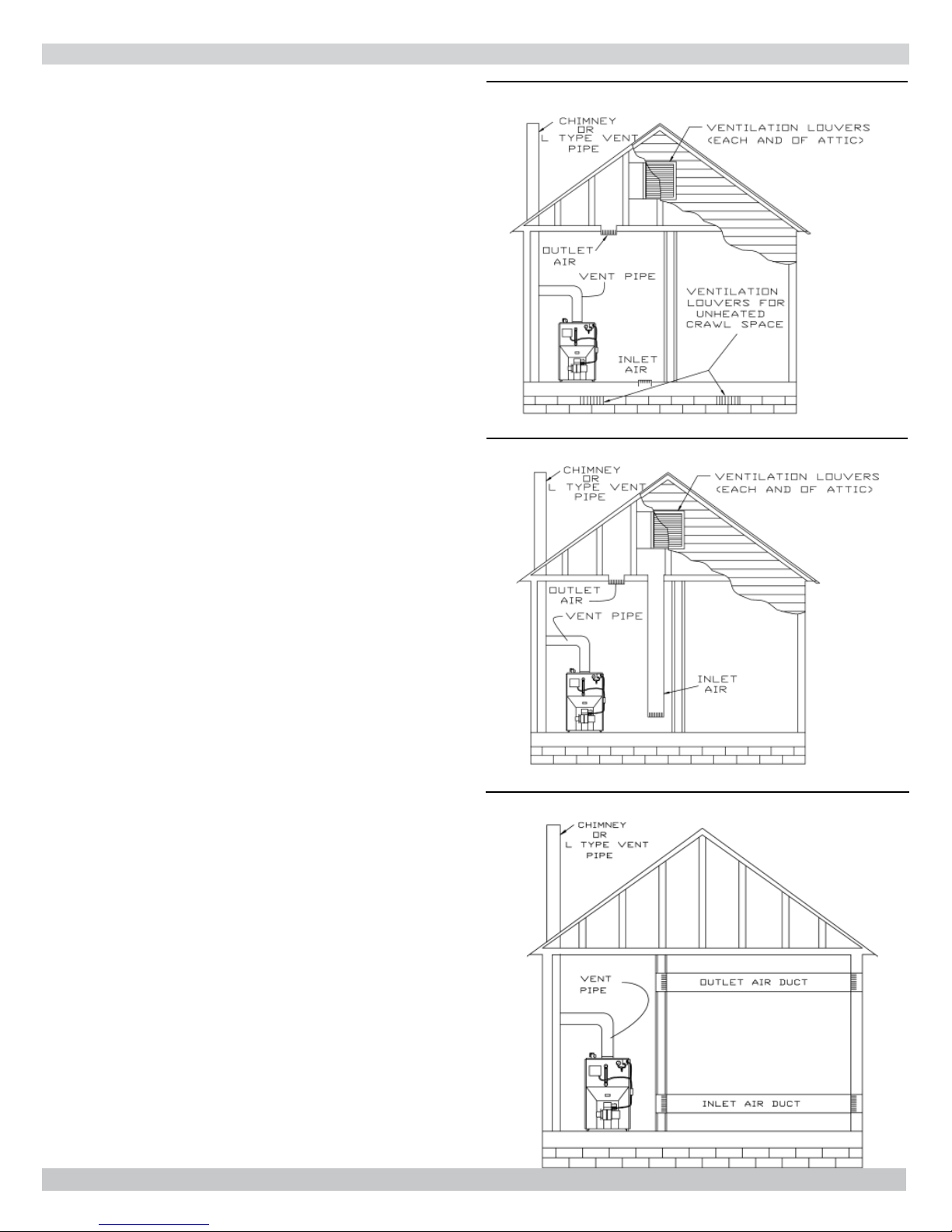
5.
When the boiler is installed in a confi ned space and
all air is provided from the outdoors, the confi ned
space shall be provided with two permanent openings,
one commencing within 12 inches from the top and
one commencing 12 inches from the bottom of the
enclosure. The openings shall communicate directly, or
by ducts, with the outdoors or spaces (crawl or attic)
that freely communicate with the outdoors. One of the
following methods must be used to provide adequate
air for ventilation and combustion.
A. When directly communicating with the outdoors,
each opening shall have a minimum free area of 1
square inch per 4,000 BTU per hour of total input
rating of all equipment in the enclosure. (Figure
#4)
B. When communicating with the outdoors by means
of vertical ducts, each opening shall have a
minimum free area 1 square inch per 4,000 BTU
per hour of total input rating of all appliances in the
enclosed space. (Figure #5)
C. If horizontal ducts are used, each opening shall
have a minimum free area 1 square inch per 2,000
BTU per hour total input rating of all appliances in
the enclosed space. (Figure #6)
D. When ducts are used, they shall be of the same
cross sectional area as the free area of the area of
the openings to which they connect. The minimum
dimension of rectangular air ducts shall not be less
than 3 inches.
6.
In calculating free area using louvers, grills or screens
for the above, consideration shall be given to their
blocking effect. Screens used shall not be smaller than
1/4 inch mesh. If the free area through a design of
louver or grill is known, it should be used in calculating
the size opening required to provide the free area
specifi ed. If the design and free area is not known, it
may be assumed that wood louvers will have 20-25%
free area and metal louvers and grills will have 60-75%
free area. Louvers and grills shall be fi xed in the open
position or interlocked with the boiler so that they are
opened automatically during boiler operation.
Figure #4
Figure #5
Figure #6
7
SUPPLY AND RETURN PIPING
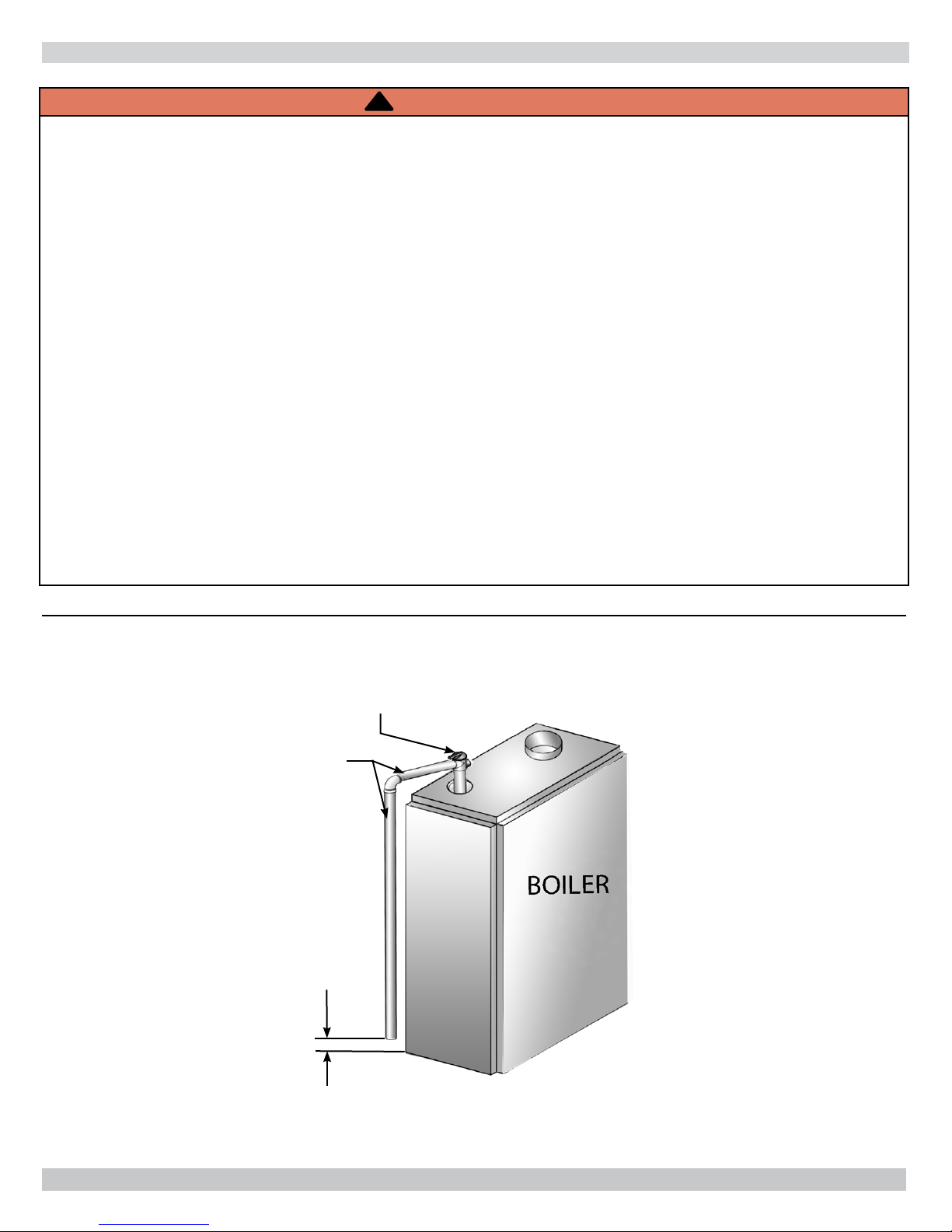
!
WARNING
Burn or Scald Hazard. Discharge line shall be installed to safety valve outlet connection to avoid burns,
scalding, or water damage due to discharge of steam and/or hot water during operation.
Discharge line shall:
• Connect to safety valve outlet. Piped down to safe point of disposal. Check local codes for maximum
distance from fl oor or allowable safe point of discharge.
• Pipe size be of equal to or greater than of safety valve outlet over entire length of discharge line.
• Have no intervening shutoff valve between safety valve and discharge to atmosphere. Do not plug or
place any obstruction in discharge line.
• Terminate freely to atmosphere where any discharge will be clearly visible and at no risk of freezing.
• Allow complete drainage of valve and discharge line.
• Install safety valve with spindle in vertical position.
• Do not install shutoff valve between boiler and safety valve.
• Support safety valve discharge piping.
• Be short and straight as possible.
• Terminate with plain end, not threaded.
• Constructed of material suitable for exposure to temperatures of 375° F (191°C); or greater.
Refer to local codes and appropriate ASME Boiler and Pressure Vessel Code for additional installation
requirements.
Figure 4 - Safety Valve
SAFETY VALVE
DISCHARGE
PIPING
Check local codes
for maximum
distance from
fl oor or other
allowable safe
point of discharge
6" Above Floor
8
 Loading...