

Columbia CSFE0365, CSFE4125, CSFE4100, CSFE3100, CSFE4150 Installation, Operation & Maintenance Manual
...
MODEL NUMBERS:
CSFE0365, CSFE3100,
CSFE4100, CSFE4125,
CSFE4150, CSFE5175,
CSFE5200, CSFE6225,
CSFE7275
CSFE STEAM
OIL-FIRED CAST IRON BOILER
INSTALLATION, OPERATION &
MAINTENANCE MANUAL
PATENT 7,823,544
C
OLUMBIA
Main offi ces and Factory: Pottstown, PA
C
OMPANY
P/N 240007513, Rev. G [05/2012]

H
INSTALLATION MANUAL AND OPERATING INSTRUCTIONS
TABLE OF CONTENTS
Ratings, Data, And Dimensions ........................ 3
Installation Procedure ....................................... 4
Ventilation And Combustion Air ........................ 5
Connecting Supply And Return Piping ............. 7
Venting System Inspection & Installation.......... 8
Oil Tank And Piping .......................................... 8
Electrical Wiring ................................................ 9
Thermostat Installation ..................................... 9
Normal Sequence Of Operation ..................... 13
Operating Instructions .................................... 13
Maintenance Procedures................................ 15
Service Checklist ............................................ 17
Replacement Parts ......................................... 18
KEEP THIS MANUAL NEAR BOILER
RETAIN FOR FUTURE REFERENCE
SAFETY SYMBOLS
The following defi ned symbols are used throughout this
manual to notify the reader of potential hazards of varying
risk levels.
IMPORTANT: Read the following instructions
COMPLETELY before installing!!
WARNING
1. Keep boiler area clear and free from
combustible materials, gasoline and
other fl ammable vapors and liquids.
2. DO NOT obstruct air openings to the
boiler room.
3. Modifi cation, substitution or elimination
of factory equipped, supplied or specifi ed
components may result in property
damage, personal injury or the loss of
life.
!
4. TO THE OWNER - Installation and
service of this boiler must be performed
by a qualifi ed installer.
5. TO THE INSTALLER - Leave all
instructions with the boiler for future
reference.
6. When this product is installed in the
Commonwealth of Massachusetts the
installation must be performed by a
Licensed Plumber or Licensed Gas
Fitter.
DANGER
!
Indicates a hazardous situation which, if not
avoided, WILL result in death or serious injury.
WARNING
!
Indicates a hazardous situation which, if not
avoided, could result in death or serious injury.
CAUTION
Indicates a hazardous situation which, if not
!
avoided, may result in minor or moderate
injury.
NOTICE
Indicates information which should be followed
to ensure proper installation and operation.
WARNING
All installations of boilers and venting
should be done only by qualifi ed expert
and in accordance with this manual.
Installing or venting a boiler or any other
!
gas appliance with improper methods
or materials may result in serious injury
or death due to fi re or to asphyxiation
from poisonous gases such as carbon
monoxide which is odorless and
invisible.
PATENT 7,823,544
Tested For 15 psi.
ASME
Working Pressure
2
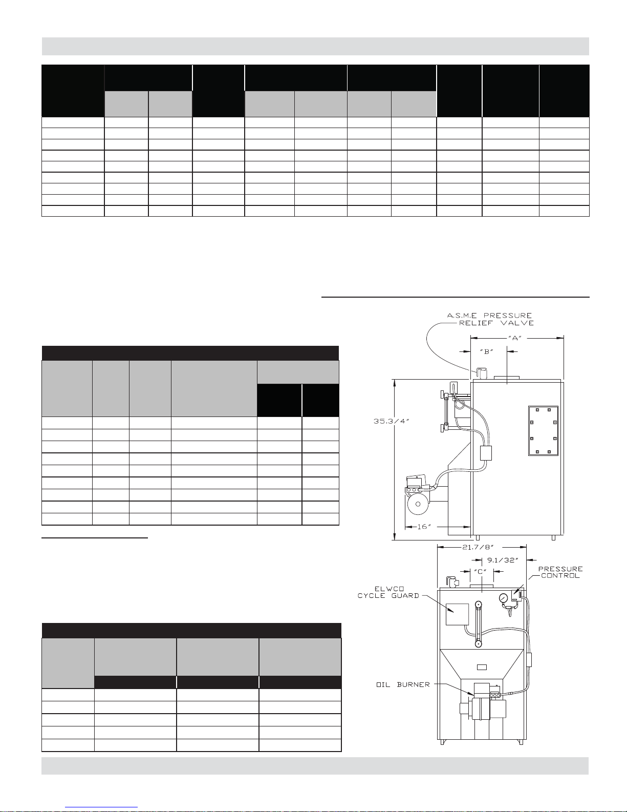
RATINGS, DATA, AND DIMENSIONS
Oil Burner Input
Boiler Model
(1)
Number
365S 0.65 91 79 59 246 6 8x8x15 140 .60 80B 85
3100S 1.00 140 116 87 363 6 8x8x15 140 .85 80B 81.5
4100S
4125S 1.25 175 145 109 454 7 8x8x15 140 1.10 60B 82.5
4150S 1.50 210 170 128 533 7 8x8x15 140 1.25 80B 81
5175S 1.75 245 202 152 633 8 8x8x15 140 1.50 80B H 83
5200S 2.00 280 227 170 708 8 8x8x15 140 1.75 70B H 82
6225S 2.25 315 251 188 783 8 8x12x15 140 2.00 45B 7275S 2.75 385 307 230 958 8 8x12x15 140 2.25 60B -
NOTES:
1. Add suffi x "T" to denote boiler with tankless heater.
2. Burner capacity is based on an oil heating value of 140,000 Btu/gal. and with 13% CO
3. Net Steam Ratings based on piping and pick-up allowance of 1.333. Consult manufacturer for unusual piping and pick-up temperatures.
4. For altitudes above 2,000 ft. ratings maybe reduced at the rate of 4% for every 1,000 ft. above sea level.
5. Nozzle sizes with an H designation are Hago brand, all others are Delavan.
6. Electrical service is 120 Volts, 15 Amps, 60 Hz.
7. MEA number for this boiler series is 182-86E.
8. MEA number for the AFG Beckett Burner used in this boiler series are;
AF/156-77-E, AFG/213-83-E, AFII 85/24-92-E, AFII 150/ 456-90-E.
9. Output is "Heating Capacity," for units with input <300 Mbh and "Gross Output"
for units ≥300 Mbh.
Boiler Model
Number
G.P.H. MBH
1.00 140 120 91 377 7 8x8x15 140 .85 80B 85
TANKLESS WATER HEATER CAPACITIES
Firing
Rate
G.P.H.
Tankless
Heater
Number
(2)
Output
(4)(9)
MBH
(4)
Tankless Heater Capac-
ity Intermittent Draw
G.P.M.
Steam
Net Ratings
MBH
Boiler Water Content
(Gallons)
To Water
Line
(3)(4)
Sq. Ft.
Steam
Figure #1
To LWCO
Line
Min. Natural Draft
Chimney Size
Round
.
2
Square
Pump
Pressure
PSI
Nozzle
Furnished
140PSIG
(5)
A.F.U.E.
Rating
365S 0.65 L-24 Available on request 11 8
3100S 1.00 L-24 4.5 11 8
4100S
4125S 1.25 L-24 4.5 13 9
4150S 1.50 L-24 4.5 13 9
5175S 1.75 L-24 5.0 15 10
5200S 2.00 L-24 5.0 15 10
6225S 2.25 L-24 5.0 17 11
7275S 2.75 L-24 5.0 19 12
1.00 L-24 4.5 13 9
ST ANDARD EQUIPMENT: Crated boiler, fl ush jacket, oil burner, target
wall/liner, ASME relief valve, steam water level gauge, steam pressure
gauge, steam pressure control, mechanical low water cut-off, drain valve,
wiring harness, burner electric disconnect, plastic cover, 2" supply tapping,
1½" return tapping, skim port, and primary control.
(NOTE: For tankless heater units, add tankless hot water coil, and 4006
limit control.)
DIMENSIONS (See Figure A)
Front of Jacket to
Center Line of Flue
Outlet
Boiler No.
Length of Flush
Jacket
-A- -B- -C-
3S 16.375" 6.5" 6.0"
4S 20.25" 8.5" 6.0"
5S 23.875" 10.25" 7.0"
6S 27.5" 8.3125" 8.0"
7S 31.125" 8.3125" 8.0"
Flue Outlet Diam-
eter
3
INSTALLATION PROCEDURE
WARNING
replacement of another appliance such as a water heater.
The boiler shall be installed such that the oil ignition system
!
Improper installation, adjustment,
alteration, service or maintenance can
cause injury or property damage.
components are protected from water (dripping, spraying,
rain etc.) during appliance operation and service.
All installations must conform to the requirements of the
authority having jurisdiction. Such applicable requirements
take precedence over the general instructions of this
manual.
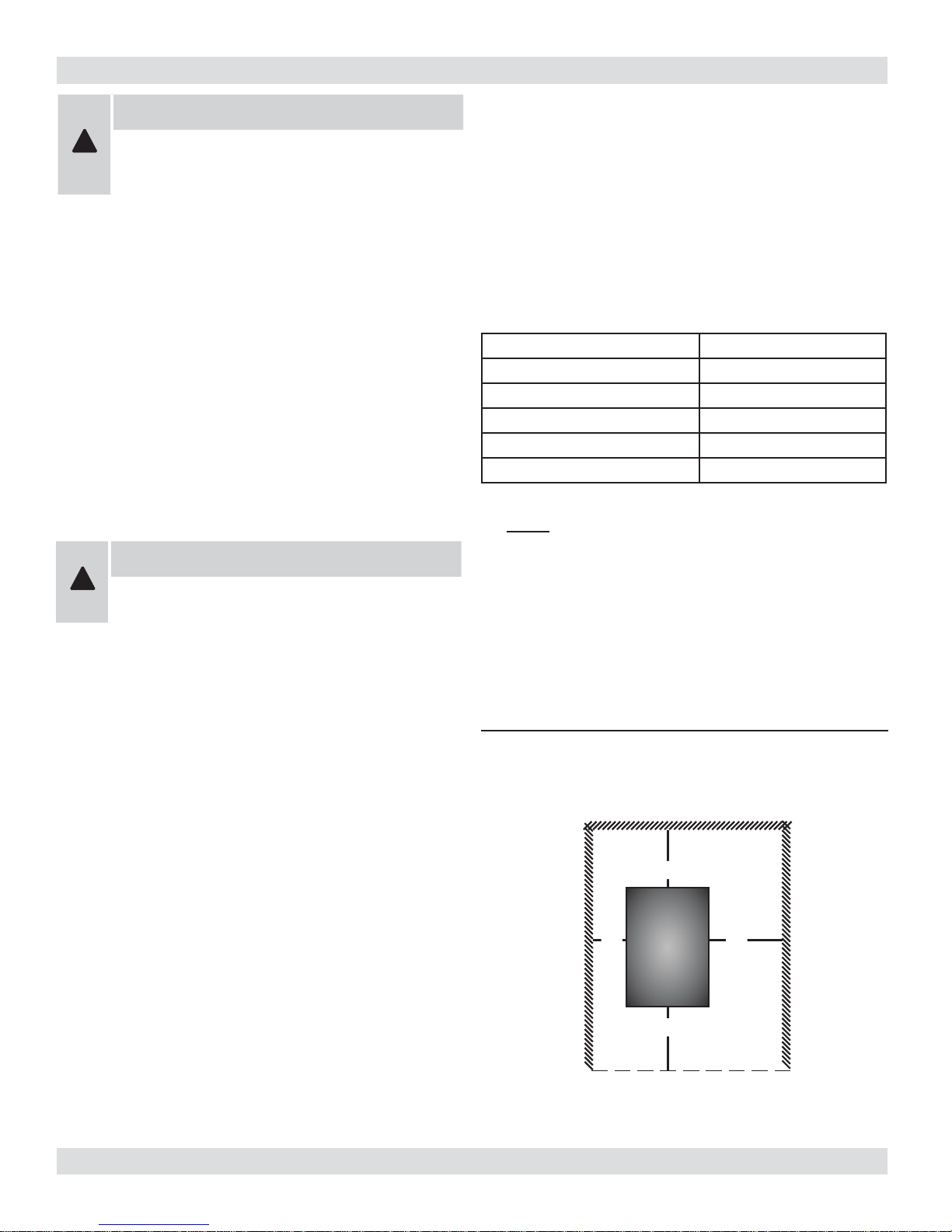
FOR INSTALLATION ON NON-COMBUSTIBLE FLOORS
ONLY - The boiler must not be installed on carpeting
or vinyl fl ooring. Minimum clearances to combustible
construction are:
Where required by the authority having jurisdiction, the
installation must conform to the American Society of
Mechanical Engineers Safety Code for Controls and Safety
Devices for Automatically Fired Boilers, ANSI/ASME No.
CSD-1.
Locate boiler in front of fi nal position before removing crate.
Provide a level solid base as near chimney as possible and
centrally located with respect to the heat distribution system
as practical.
WARNING
!
Boiler may not be installed on combustible
fl ooring.
TOP 24 IN.
FRONT 24 IN.
FLUE CONNECTOR 9 IN.
REAR 24 IN.
LEFT SIDE 6 IN.
RIGHT SIDE 24IN.
NOTE: Clearance for access should exceed fire protection
clearance.
Allow 24 inches in the front, top and right hand side for
servicing and cleaning, or removing tankless water heating
coil.
It is recommended that 24 inches be allowed in back of
Figure #2
boiler for convenience when skimming hole is used.
When installed in a utility room, the door should be wide
enough to allow the largest boiler part to enter, or to permit
Minimum clearances to combustible
construction (as seen from above)
24"
6" 24"
BOILER
24"
4
VENTILATION AND COMBUSTION AIR
WARNING
!
Air openings to combustion area must not be obstructed. By following the instructions below,
adequate combustion air can be maintained.
COMBUSTION AIR REQUIREMENTS
(Minimum Opening Requirement)
Unconfi ned Area* Confi ned Area**
Outside Inside Outside Combustion Air
BTU/Hr Input
91,000 19 100 23 46
140,000 28 140 35 70
175,000 35 175 44 88
210,000 42 210 53 106
245,000 49 245 61 122
280,000 56 280 61 140
* A space whose volume is not less than 50 cubic feet per 1000 BTU/Hour of all appliances installed in that space (cubic feet of space = height x width x length)
** A space whose volume is less than 50 cubic feet per 1000 BTU/Hour of all appliances installed in that space (cubic feet of space = height x width x length)
Combustion Air 1 Sq.
In./5000 BTU/Hr
(Step 4)
Combustion Air 1 Sq.
In./1000 BTU/Hr
(Min. 100 Sq. In.) (Figure #1)
Vertical Ducts 1 Sq. In./4000 BTU/
Hr (Figures # 2 & #3)
Horizontal Ducts 1 Sq. In./2000
BTU/Hr (Figure # 4)
1.
Ventilation of boiler room must be adequate enough to
provide suffi cient air to properly support combustion,
venting and maintain safe ambient temperatures under
normal operating conditions.
2.
When the boiler is located in an unconfi ned space in a
building of conventional construction frame, masonry
or metal, infi ltration normally is adequate to provide
air for combustion and ventilation. However, in any
building which has been altered to conserve energy
or to minimize infi ltration, the boiler area should
be considered as a confi ned space. If there is any
doubt, install air supply provisions for combustion
and ventilation in accordance with Chapter 5, Air for
Combustion and Ventilation, of NFPA 31, Standard
for the Installation of Oil Burning Equipment. The
recommendations that follow, or applicable provisions
of the local building codes.
3.
When the boiler is installed in an unconfi ned space,
in a building of unusually tight construction, air for
combustion and room ventilation must be obtained from
outdoors or from spaces freely communicating with the
outdoors. A permanent opening or openings having a
total free area of not less than 1 square inch per 5,000
BTU per hour of total input rating of all appliances shall
be provided. Ducts may be used to convey make-up
air from the outdoors and shall have the same crosssectional area of the openings to which they are
connected.
4.
When air for combustion and room ventilation is from
inside buildings, the confi ned space shall be provided
with two permanent openings, one starting 12 inches
from the top and one 12 inches from the bottom of the
enclosed space. Each opening shall have a minimum
free area of 1 square inch per 1,000 BTU per hour of
the total input rating of all appliances in the enclosed
space, but must not be less than 100 square inches.
These openings must freely communicate with the
interior areas having adequate infi ltration from the
outside. See Figure #3.
Figure #3
CHIMNEY
OR
L TYPE VENT PIPE
BASEBOARD
VENT PIPE
12"
VENTS
12"
5
VENTILATION AND COMBUSTION AIR
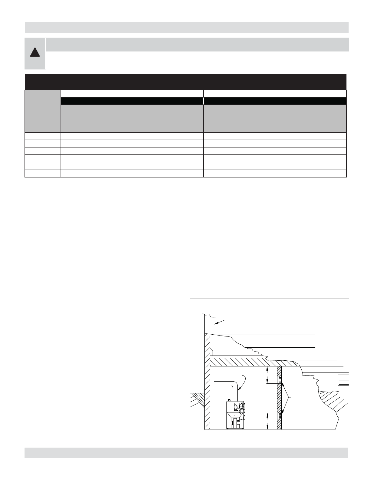
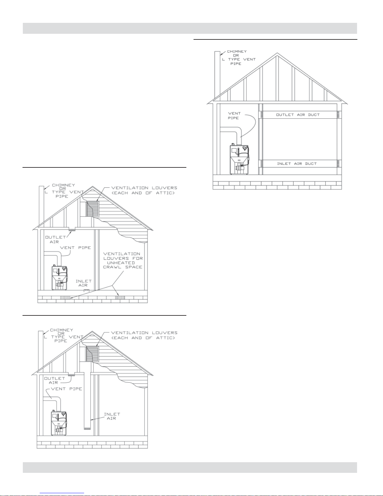
5.
When the boiler is installed in a confi ned space and
all air is provided from the outdoors, the confi ned
space shall be provided with two permanent openings,
one commencing within 12 inches from the top and
one commencing 12 inches from the bottom of the
enclosure. The openings shall communicate directly,
or by ducts, with the outdoors or spaces (crawl or attic)
that freely communicate with the outdoors. One of the
following methods must be used to provide adequate
air for ventilation and combustion.
A. When directly communicating with the outdoors, each
opening shall have a minimum free area of 1 square
inch per 4,000 BTU per hour of total input rating of all
equipment in the enclosure. (Figure #4)
Figure #4
Figure #5
Figure #6
B. When communicating with the outdoors by means of
vertical ducts, each opening shall have a minimum
free area 1 square inch per 4,000 BTU per hour of
total input rating of all appliances in the enclosed
space. (Figure #5)
C. If horizontal ducts are used, each opening shall have
a minimum free area 1 square inch per 2,000 BTU per
hour total input rating of all appliances in the enclosed
space. (Figure #6)
D. When ducts are used, they shall be of the same
cross sectional area as the free area of the area of
the openings to which they connect. The minimum
dimension of rectangular air ducts shall not be less
than 3 inches.
6.
In calculating free area using louvers, grills or screens
for the above, consideration shall be given to their
blocking effect. Screens used shall not be smaller than
1/4 inch mesh. If the free area through a design of
louver or grill is known, it should be used in calculating
the size opening required to provide the free area
specifi ed. If the design and free area is not known, it
may be assumed that wood louvers will have 20-25%
free area and metal louvers and grills will have 60-75%
free area. Louvers and grills shall be fi xed in the open
position or interlocked with the boiler so that they are
opened automatically during boiler operation.
6
CONNECTING SUPPLY AND RETURN PIPING
CHECK
VALVE
BLOWOFF
VALVE
SOLENOID
VALVE
(OPTIONAL)
F & T TRAP HIGH
LEVEL "SPILL"
(DO NOT USE WITH
CONDENSATE PUMP)
TO
RECEIVER
TANK
STEAM MAIN
TRAP
TO
SYSTEM
FROM
RECEIVER
TANK
FROM
RECEIVER
TANK
STOP
VALVE
TO
RECEIVER
TANK
STOP
VALVE
COLD WATER IN
UNTEMPERED
HOT
FLOW
REGULATOR
TEMPERING VALVE
COLD WATER
DOMESTIC
HOT
WATER
T & P VALVE
UNTEMPERED HOT
WATER TO
AUTOMATIC WASHER
CONTROL
WATER
INSTALLED BELOW CENTER
LINE OF BOILER HOT
CONNECTION
RETURN
2"
TO
SYSTEM
STOP
VALVE
BLOWOFF
VALVE
STOP
VALVE
CHECK
VALVE
(OPTIONAL)
STEAM MAIN
WATER
LINE
28"
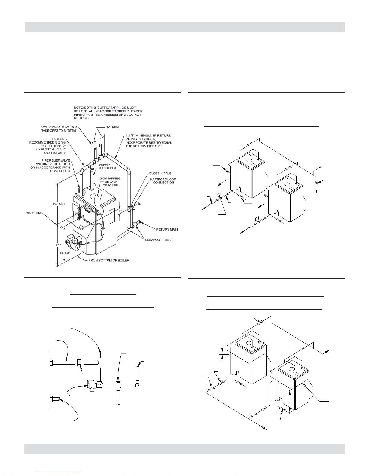
1.
Suggested piping for steam heating system can be
seen in Figure #7. Actual piping may vary based on
system design and local conditions.
2.
For further piping information refer to the I=B=R
installation piping guide.
3.
See Figure #8 for typical piping for domestic hot water
heater.
4.
See Figures #9 and #10 for the suggested piping for a
modular steam boiler.
Figure #7
Figure #9
SUGGESTED PIPING FOR MODULAR
STEAM BOILERS - PUMPED RETURN
Figure #8
PIPING FOR BUILT-IN
DOMESTIC HOT WATER HEATER
Figure #10
SUGGESTED PIPING FOR MODULAR
STEAM BOILERS - GRAVITY RETURN
7
VENTING SYSTEM INSPECTION & INSTALLATION
RIDGE
2’ (.61 M) MIN.
MORE THAN 10’ (3.1 M)
10’ (3.1 M)
HEIGHT ABOVE ANY
ROOF SURFACE WITHIN
10’ (3.1 M)
HORIZONTALLY
CHIMNEY 3’ (.92 M)
GAS VENT OR
TYPE L VENT
2’ (.61 M) MIN.
WARNING
Boiler is to be vented by natural draft and
!
shall not be connected into any portion of
mechanical draft operating system under
positive pressure.
Inspect chimney to make certain it is constructed according
If oil fi red water heater is vented into same fl ue as boiler,
provide separate hole into chimney whenever possible.
When this isn’t possible, use “Y” connection in fl ue pipe,
using separate draft regulator for each unit. When chimney
will not provide adequate draft to handle input from water
heater and boiler simultaneously, wire units so only one will
operate at a time, favoring water heater.
to the latest revision of the NFPA 211. Local regulations
may differ from this code and should be checked. Where
Figure #11
there is a confl ict, the local code will prevail.
The boiler must be installed into a chimney which has a
masonry or metallic chimney liner.
An unlined chimney will have leaks that will cause poor
chimney performance (no draft), and could result in a
positive pressure in the combustion chamber.
Horizontal portions of the venting system should not exceed
10 feet in length. Horizontal lengths over 10 ft. will have a
negative effect on the chimney performance.
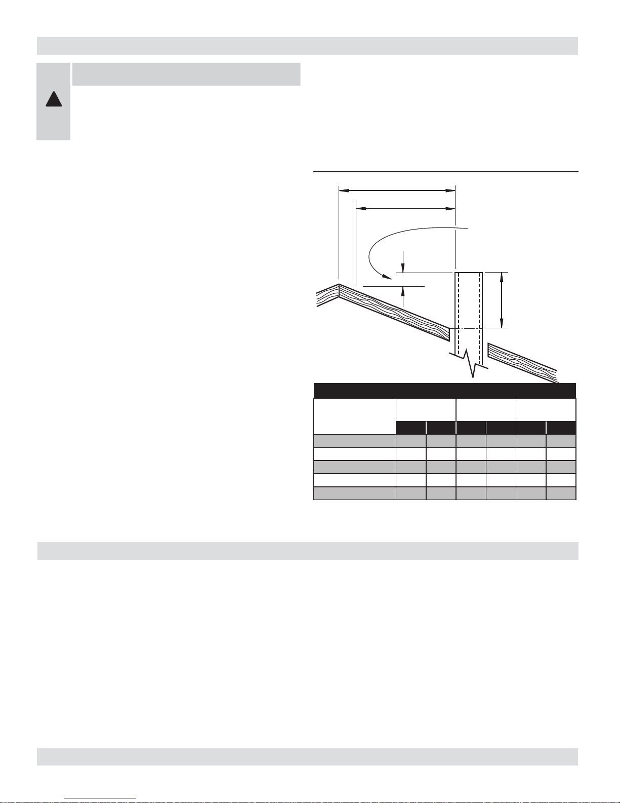
The chimney should extend at least 2 ft. above any portion
of the building within 10 ft. (Figure #11) It should produce
a -.02 inch W.C. draft in the combustion chamber. See
"Chimney or Vent Sizes" chart for recommended minimum
and maximum chimney or vent sizes.
Inadequate draft will cause improper combustion, resulting
in dirty fl ue ways and high fuel bills.
Connect fl ue pipe same size as boiler outlet to chimney,
sloping upward continuously toward the chimney
91,000 - 140,000 6 8 8x8 8x8 15 40
175,000 - 210,000 7 8 8x8 8x10 15 40
245,000 - 280,000 8 10 8x8 8x12 15 50
approximately ¼" per foot. Bolt or screw joints together to
avoid sag.
CHIMNEY OR VENT SIZES
ROUND
BTU/HR INPUT
315,000 8 10 8x8 8x12 15 50
385,000 8 10 8x8 8x12 15 50
INCHES
MIN MAX MIN MAX MIN MAX
SQUARE
INCHES
HEIGHT (FT)
Oil tank and piping should be installed in accordance with
National Board of Fire Underwriters and local regulations.
Oil storage tank, vent, fi ll pipe and caps should be as
prescribed by local codes. In no case should vent pipe be
smaller than 1¼" I.P.S. Fill pipe should not be less than 2"
I.P.S.
OIL TANK AND PIPING
Ssuction line from tank to burner should be one continuous
piece of tubing to prevent air entering line. Suction line,
must be ⅜" O.D. copper tubing for runs of 50 feet or less,
and ½" O.D. for longer runs. Oil return line, same size as
suction line, must be used on any installation where bottom
of tank is below fuel unit of burner. Oil lines should be
buried or otherwise protected from mechanical injury. Flare
fi ttings on all oil lines are recommended. Compression
fi ttings on suction line often allow air to be drawn into fuel
pump, making it diffi cult to maintain oil pressure at nozzle.
Do not run overhead fuel lines from tank to oil burner.
8
 Loading...